code of practice for water infrastructure
TRANSCRIPT
Code of Practice for Water Infrastructure
Connections and Developer Services
Design and Construction Requirements for Self-Lay Developments July 2020 (Revision 2)
Document IW-CDS-5020-03
IW-C
DS-
50
20-0
3

IW-CDS-5020-03 (Revision 2 – 2020)

IW-CDS-5020-03 (Revision 2 – 2020)
i
SCOPE This Code of Practice outlines acceptable typical design and construction details that are required by Irish Water for the provision of water supply pipes and related infrastructure in Self-Lay Developments which are to be connected to the Irish Water Network. It shall be used in conjunction with the associated Design Risk Assessments that have been developed which identify the risks that designers shall take into account in the detailed design of the water supply pipes and related infrastructure to be connected to the Irish Water Network. The pipes and related infrastructure to be put in place within Developments shall comply fully with this Code of Practice. Ultimate responsibility (including, but not limited to any losses, costs, demands, damages, actions, expenses, negligence and claims) for the detailed design, construction and provision of such pipes and related infrastructure shall rest entirely with the Developer, his/her Designer(s), Contractor(s), or other related party. Irish Water assumes no responsibility for and gives no guarantees, undertakings or warranties in relation to the pipes and related infrastructure to be provided in accordance with this Code of Practice. No part of the Code of Practice shall be reproduced or transmitted in any form or stored in any retrieval system of any nature without the written permission of Irish Water as copyright holder, except as agreed for use. This Code of Practice shall be used in conjunction with current Connection and Developer Services Standard Details. Standard Details can be found on the Irish Water website at www.water.ie/connections.
Revision Log
Date Details of Revision Revision Author Approver
December 2016 Initial Issue 0 T’OC M’OD
December 2017 General Revision (See Appendix D)
1 T’OC M’OD
July 2020 General Revision (See Appendix C)
2 T’OC M’OD

IW-CDS-5020-03 (Revision 2 – 2020)
ii
Background Technical Documentation was developed by Irish Water’s Connection and Developer Services which outlines the requirements for water services infrastructure within Developments. The Technical Documentation comprises Codes of Practice and Standard Details. These provide Irish Water’s requirements to Developers in the provision of water infrastructure that is to be installed by Self-Lay methods in Developments and that would be connected to Irish Water’s networks and subsequently vested in Irish Water. The Technical Documentation outlines design and construction requirements to ensure consistency in the provision of materials, equipment, workmanship, etc. They will also provide the basis for developers detailed design proposals for water supply infrastructure, leading to the provision of infrastructure that is suitable for connection to Irish Water’s networks and easy operation and maintenance. The Technical Documents are based on best practice within the water industry. They take account of the experience of Local Authorities in the provision of these services to new Developments. This document (IW-CDS-5020-03) comprises the Code of Practice for Water Infrastructure and outlines design and construction for developers. It shall be read in conjunction with its associated Design Risk Assessment (IW-CDS-5020-04). The Standard Details for Water (IW-CDS-5020-01) and its associated Design Risk Assessment (IW-CDS-5020-02) are published and available on the Irish Water website at www.water.ie/connections

IW-CDS-5020-03 (Revision 2 – 2020)
iii
TABLE OF CONTENTS
Glossary of Terms and Definitions 1 Part 1 – General 9 1.1 Introduction 9 1.2 Statutory Relevance 9 1.3 Options for Connection Installation 10 1.4 Connection Procedures 10 1.5 Protection of Water Quality 11 1.6 Responsibility of Irish Water 13 1.7 Application for a Conformance Certificate 13 1.8 Conformance Certificate 16 1.9 Connection of Development to Irish Water Network 17 1.10 Vesting 17 1.11 Defects Liability Period 18 1.12 Hygiene Requirements During Defects Liability Period & Remedial Work 19 1.13 Water Audit Prior to Defects Liability Period Termination 20 1.14 Final Inspection at Defects Liability Termination 21 1.15 Completion Certificate 21 1.16 Statutory and Other Consents 22 1.17 Fire Authority Liaison 22 1.18 Regulations 23 1.19 Standards 23 1.20 Civil Engineering Specification for the Water Industry (CESWI) 24

IW-CDS-5020-03 (Revision 2 – 2020)
iv
1.21 Standard Details 24 1.22 Temporary Water Supply Connection for Construction Purposes 24 1.23 Extensions to Undeveloped Contiguous Areas 25 Part 2 – General Design Requirements and Submissions 26 2.1 Introduction 26 2.2 General Design Requirements 26 2.3 Design Submissions 27 2.4 Drawings, Calculations and Design Information 29 2.5 Hydraulic Modelling 31 2.6 General Minimum Requirements 32 Part 3 – Design Requirements 34 3.1 Compliance 34 3.2 Reliability and Design Objectives 34 3.3 Materials – General Requirements 35 3.4 Structural Design and Integrity – Specific Requirements 36 3.4 Layout of Works 37 3.6 Separation Distances 42 3.7 Sizing of Water Mains 43 3.7.1 General 43 3.7.2 Water Demand Calculations 44 3.8 Service Connections to Individual Premise –
Sizing and General Requirements 45 3.9 Materials Selection: Mains and Service Connections 47 3.10 Pipe Joints 49

IW-CDS-5020-03 (Revision 2 – 2020)
v
3.10.1 General 49 3.10.2 Jointing of Polyethylene Pipes 50 3.10.3 Auditing and Testing of Polyethylene Pipe Joints 50 3.11 Depth of Cover 53 3.12 Roadway/Footway Surface Reinstatement 54 3.13 Boosted Water Supplies 54 3.14 Boundary Boxes 56 3.15 Meters 57 3.15.1 General 57 3.15.2 Domestic Meters 58 3.15.3 Meters for Commercial Premises 59 3.15.4 Bulk Meters 59 3.16 Fittings 61 3.16.1 General 61 3.16.2 Sluice Valves 61 3.16.3 Butterfly Valves 62 3.16.4 Scour Valves 63 3.16.5 Hydrants (80mm) 64 3.16.6 Air Valves 65 3.16.7 Other Fitting Materials 67 3.17 Pressure Reducing/Sustaining Valves 68 3.18 Hydrant, Air Valve, Sluice Valve and Scour Valve Chambers 69 3.19 Water Meter Chambers 72
IW-CDS-5020-03 (Revision 2 – 2020)
vi
3.20 Pressure Reducing/Sustaining Valve Chambers 74 3.21 Scour Chambers 75 3.22 Washout Hydrants 76 3.23 Indicator Marker Plates and Posts 77 3.24 Warning Tape 77 3.25 Existing Utilities 78 3.26 Environmental Considerations 78 3.27 Working Near Existing Pipes (Notifications and Separation Distances) 80 3.28 Water Storage 81 3.29 Water Management and Conservation 83 Part 4 – Construction Requirements 84 4.1 Construction – General Requirements 84 4.2 Transportation, Storage, Handling and Use of Materials 85 4.3 Location of Other Utilities 86 4.4 Trench Widths 86 4.5 Trench Base 87 4.6 Anchor/Thrust/Support Blocks 87 4.7 Cleaning Pipes 88 4.8 Pipe Bedding, Haunch and Surrounds 89 4.9 Backfill 90 4.10 Testing and Commissioning 92 4.10.1 General 92 4.10.2 Cleansing of Pipes 92

IW-CDS-5020-03 (Revision 2 – 2020)
vii
4.10.3 Pressure Testing 93 4.10.3.1 General 93 4.10.3.2 Testing of Ductile Pressure Pipelines 93 4.10.3.3 Testing of Polyethylene Pipelines 95 4.10.4 Swabbing after Testing 96 4.10.5 Disinfection 96 4.10.6 Disposal of Water 97 4.10.7 Flushing 98 4.11 Water Quality Sampling and Testing 98 4.12 Connection to the Water Network 99 4.13 Final Flushing of Water Mains 100 4.14 Service Connection to Water Supply Distribution System 100 4.14 Final Documents 102 4.15 Repairs, Hygiene Requirements 103 Part 5 – Booster Pumping Stations, Kiosks and Ancillary Works 104 5.1 Introduction 104 5.2 Booster Pump Station – Design Submission Requirements 105 5.3 Booster Pump Stations – Technical Requirements 105 5.4 Booster Station Pump Types and their Requirements 106 5.5 Booster Station Testing and Commissioning 107 5.6 Booster Station Pump Efficiency 107 5.7 Booster Station Pressure Control 108 5.8 Flow Metering 108

IW-CDS-5020-03 (Revision 2 – 2020)
viii
5.9 Kiosk Requirements 108 5.10 Structure Enclosures 111 5.11 Cable Ducts and Chambers 111 5.12 General Electrical Requirements 113 5.13 Cables 114 5.14 Cable Installation 116 5.14.1 General 116 5.14.2 Glanding 116 5.14.3 Termination 116 5.14.4 Junction Boxes 116 5.14.5 Identification of Wiring 117 5.15 Control Panels – General Requirements 117 5.16 Form 4 Control Panel Compartment – Additional Requirements 118 5.16.1 Incoming Section 119 5.16.2 Control Circuit Supply 119 5.16.3 Motor Starter Compartments 120 5.17 Earthing and Bonding 120 5.17.1 Earth Electrodes 120 5.17.2 Bonding 121 5.18 Control Philosophy 121 5.19 Testing 121 5.20 Abnormal Operation 122 5.20.1 Power Failure 122
IW-CDS-5020-03 (Revision 2 – 2020)
ix
5.20.2 Pump Failure 122 5.21 Telemetry 122 5.22 Dial Out Alarm 123 5.23 Operation and Maintenance Manual 124 Appendix A Specification for Boundary Box and Fittings 125 Appendix B Standards Referenced in the Water Code of Practice 129 Appendix C Amendments Associated with change from
Revision 1 (December 2017) to Revision 2 (July 2020) 136
IW-CDS-5020-03 (Revision 2 – 2020)
1
Glossary of Terms and Definitions In this document, the following terms and definitions apply - “the Act” means the Water Services Act 2007 – 2014; “Accessories” means all Manholes, Chambers, tanks, fittings, valves, or any machinery or other apparatus which is designed or adapted for use in connection with the use or maintenance of the Works; “Applicant” means a Developer who has made an application for a connection to Irish Water’s Network; “Application to Connect” means an application by applicant Developer for a connection to Irish Water’s Network; “Backfill” means suitable material that is used to replace excavated material around a structure or that is used in a pipe trench to replace excavated material above the granular surround of the pipe to the underside of the roadway/footway construction or the underside of the top-soil reinstatement in a green area as set out in this Code of Practice; “Boundary” means the outer edge of the curtilage of the Developer’s Premises or the Developer’s Development; “Boundary Box” means an on line, below ground proprietary enclosure containing a stop valve, a water meter and associated fittings forming part of the Service Connection and located normally at the public side of a Curtilage Boundary. “Brownfield” means an area that has already been developed; “Building Regulations” mean the Building Control Acts 1990 to 2014 and all subordinate legislation and regulations made pursuant to the said Acts including, without limitation the Building Control Regulations 1997 to 2015, the Building Regulations 1997 to 2017 and relevant codes of practice, and any amendment, update or replacement or repeal thereof; “Business Day” means every day other than a Saturday or Sunday or bank or public holiday in Ireland; “Capital Investment Plan (CIP)” means the document outlining a programme of schemes and contracts identified by Irish Water for advancement to various stages in a specific time period and published by Irish Water as required under Section 34 of the Water Services (No 2) Act 2013 which sets out and particularises the investment in Water Services infrastructure that Irish Water considers necessary for the effective performance by it of its functions in a particular period;

IW-CDS-5020-03 (Revision 2 – 2020)
2
“Chamber” means an enclosed structure which may contain Pipes, Accessories and related fittings including meters, etc.; “Chartered Engineer” means a professional engineer with a registered professional title of Chartered Engineer who is a members of Engineers Ireland or a professional engineer with the same status as the professional engineering titles used in other countries and who has experience in the provision of water services infrastructure; “Commission for Regulation of Utilities (CRU)” means the body established pursuant to Section 8 of the Electricity Regulation Act 1999, formerly the Commission for Energy Regulation (CER) as amended; “Completion Certificate” means a written certificate issued by Irish Water to the Developer at the end of the Defects Liability Period in accordance with the Connection Agreement; “Conformance Certificate” means a written certificate issued by Irish Water to the Developer following satisfactory completion of construction, inspection and commissioning of the Works and the provision of the Final Documentation pursuant to this Code of Practice in accordance with the Connection Agreement; “Connection” means the physical connection to the Network to facilitate the provision of Water Services to the Developer’s Development; “Connection Agreement” means a written agreement entered into between the Developer and Irish Water facilitating the connection of the Water and Wastewater Services Infrastructure to the Network(s) and setting the commercial and technical terms governing the Connection; “Connection Application” means the application submitted by the Developer to Irish Water in relation to the Service Connection(s), as included in the Connection Offer; “Connection Offer” means the conditional offer letter issued to the Developer by Irish Water relating to the connection of the Water and Wastewater Services Infrastructure to the Network(s) and which details the connection terms and conditions that are offered to the Developer; “Connection Point(s)” means the location or locations to be determined by Irish Water (which may be outside the boundary to the curtilage of the Development) at which the Water & Wastewater Services Infrastructure is to be connected to the Waterworks (where, as specified in the Connection Offer, the Developer requires connection to the Waterworks) or the Wastewater Works (where, as specified in the Connection Offer, the Developer requires connection to the Wastewater Works) (via the Service Connection(s)). Connection Points may differ for Waterworks and Wastewater Works;
IW-CDS-5020-03 (Revision 2 – 2020)
3
“Connection Works” means the permanent and temporary works and services to be performed by or on behalf of Irish Water in the acquisition, design, procurement, construction, and installation of the Connection Facilities, and the obtaining of permits, and all Requisite Consents and the tie-in and commissioning of a Connection Point(s) in accordance with the requirements of this Connection Agreement; “Construction Regulations” means the Safety Health and Welfare at Work Act 2005, the Safety Health and Welfare at Work (General Application) Regulations 2007 to 2016 as amended, the Safety Health and Welfare at Work (Construction) Regulations 2013 as amended and any guidance requirements issued from time to time from the Health and Safety Authority; “Customer” means a Developer who intends to provide Works for housing, mixed use or industrial/commercial Development and who intends to or has applied to enter into a Connection Agreement or has entered into a Connection Agreement; “Curtilage” means an area of land immediately surrounding a building or group of building structures which is used for the enjoyment of such building, group or building structures; “Deed of Grant of Easement” means the Deed(s) of Grant of Wayleaves and Easements referred to in the Connection Agreement; “Defects Liability Period” means a minimum period of 12 months or such other period as may be specified by Irish Water in the Connection Agreement, between the issue of the Conformance Certificate and the issue of a Completion Certificate during which the Developer is responsible under the Connection Agreement for the cost of rectification of any defects in or connected to the Works; “Defects Report” means a list of correction works that is issued with the Conformance Certificate that Irish Water’s field engineers have identified and which require remediation by the Developer; “Developer” means the person or entity to whom the Connection Offer is addressed and who has entered into the Connection Agreement with Irish Water; “Development” means the housing or housing/mixed use or industrial/commercial development located at the address set out in the Connection Offer and identified in the map set out in the Connection Offer, including the Premises, the Water and Wastewater Services Infrastructure to be constructed pursuant to the Connection Agreement and all ancillary infrastructure relating thereto; “Distribution System” means a pipe and its related fittings, that is used or to be used as the case may be to convey water into or through one or more Premises (including

IW-CDS-5020-03 (Revision 2 – 2020)
4
any related internal or external taps) excluding a Service Connection as defined below, and also excluding where it is taken in charge by Irish Water; “Domestic Use” means Water Supply used for the day to day domestic requirements including drinking, washing and sanitation; “Easement” means a legal right or interest over a person’s real property for a specific purpose; “Final Documents” means the suite of documents as set out in Section 1.7 of this Code of Practice; “Fire Authority” means the relevant Local Authority exercising its Fire Authority functions; “Fire Flow” means the water flow required for fire fighting purposes; “Greenfield” means an area that has not previously been developed; “Irish Water” means Irish Water (Uisce Eireann), a designated activity company incorporated in Ireland (company registration number 530363) and having its registered office at Colvill House, 24-26 Talbot Street, Dublin 1, Ireland; “Local Authority” means the County Council or City Council (as defined in the Local Government Act 2001) responsible for the functional area within which the Developer’s Premises is located and which is referred to in the Connection Offer; “Manhole” means a large Chamber on a Sewer which facilitates human access to/egress from and safe working space at Pipe level; “Network” means the Irish Water owned and controlled Water infrastructure; “Network(s)” means the Waterworks and/or the Wastewater Works, as applicable and specified on the face of the Connection Offer, and any related lands, which are
owned by, vested in, controlled or used by Irish Water; “PRA Compliant Map” means ordinance survey plans, suitable for registration of any Deed of Grant of Wayleaves and Easements relating to property intended to be taken in charge by the Local Authority and the Water & Wastewater Services Infrastructure to be vested in Irish Water together with all easements relating thereto suitably identified by the relevant symbols and/or colours designated by the Property Registration Authority; “Pipe” includes— (a) any Water Main, Service Connection, drain, channel, culvert, drainage pipe, and (b) any system of such pipes, accessories and related fittings, including meters,
IW-CDS-5020-03 (Revision 2 – 2020)
5
that is used, designed or intended to be used to collect, store, distribute or measure water; “Premises” means any premises within the Development which are specified or referred to in the Connection Offer and includes any part of any public or private building, vessel, vehicle, structure or land (whether or not there are structures on the land and whether or not the land is covered with water), and any plant or related Accessories on or under such land, or any hereditament of tenure, together with any out-buildings and Curtilage and which is:
(a) receiving Water Services; or
(b) specified in the Connection Application; or
(c) a Premises deemed to be a Premises by Irish Water; or
(d) such other Premises as may be notified by the Customer to Irish Water and accepted by Irish Water from time to time,
but does not include land which is a Public Road, a road which is the subject of an order under Section 11 of the Roads Act 1993 or a road which has been taken in charge by a Local Authority pursuant to a non-statutory Local Authority Taking in Charge scheme; “Premises Pipe Work” means the pipe, related fittings and associated accessories to be laid by the Developer within the boundary of a Premises in accordance with Relevant Standards, Requisite Consents and Applicable Laws and the Distribution System (if connecting to the Waterworks) and Drains (if connecting to the Wastewater Works), to be used to connect the Premises with the Water & Wastewater Services Infrastructure; “Public Road” means a road over which a public right of way exists and the responsibility for the maintenance of which lies on a Road Authority; “Quality Assurance Folder” means a document that is developed and retained by the Developer on site to include information about on-site quality assurance records of the Works which will be updated as required and shall be made available to the Irish Water field engineers on request for inspection and which can be used to facilitate the collation of the Final Documents; “Regulator” means where applicable all present and future regulatory bodies having regulatory oversight over Irish Water including, but not limited to, the Commission for Regulation of Utilities, the Environmental Protection Agency, the Department of Planning Housing Local Government, the Office of the Data Protection Commissioner and/or any other statutory body or regulatory authority which regulates on an on-going basis or from time to time the business or operations of Irish Water; “Relevant Standards” means the Codes of Practice and Standard Details set out in the Connection Offer;

IW-CDS-5020-03 (Revision 2 – 2020)
6
“Required Security” means the financial security required by Irish Water, as specified in the Connection Offer; “Requisite Consents” means all necessary permissions, consents, approvals, licenses, easements, certificates and permits as may be necessary for the Developer to lawfully commence, carry out, maintain and complete its obligations pursuant to this Connection Agreement; “Rising Main” means a Water Main through which water is pumped and conducted under pressure; “Road Authority” means the relevant Local Authority or Transport Infrastructure Ireland (TII) or successor exercising its road authority function; “Security” means a Surety in the form of a Bond under the Major Water and Wastewater Connection Agreement and a Self-Lay Surety under a Self-Lay Connection Agreement; “Self-Lay Works” means all works to be carried out by the Developer in connection with the construction of the Water & Wastewater Services Infrastructure, the Premises Pipe Work (which includes the Distribution System and the Drains) and any related works required to provide Water Services to the Premises within the Development, including:
(a) the provision, installation, testing and commissioning of the Water & Wastewater Services Infrastructure within the boundary of the Development; and
(b) the provision, installation, testing and commissioning of the Premises Pipe Work within the boundary to the curtilage of the Premises necessary to connect the Premises, Distribution System (if connection is to Waterworks) and Drain(s) (if connection is to Wastewater Works) to the Water & Wastewater Services Infrastructure.
These works shall be approximately in the position and at the levels indicated on drawing or drawings in the Specification and in accordance with the design that has been submitted with the Connection Application; “Service Connection” means a water supply pipe or a drainage pipe, together with any Accessories and related fittings, extending from a Waterworks or Wastewater Works to the outer edge of the boundary of the Development, and used, or to be used as the case may be, for the purpose of connecting the Water and Wastewater Services Infrastructure with the Waterworks and/or the Wastewater Works (as the case may be);

IW-CDS-5020-03 (Revision 2 – 2020)
7
“Structure” means any building, erection, structure, excavation, or other thing constructed, erected, or made on, in or under any land, or any part of a structure so defined, and, where the context so admits, includes the land on, in, or under which the structure is situated; “Taking in Charge” means the process for taking infrastructure into the sole control and responsibility of a Local Authority pursuant to Section 180 of the Planning and Development Act 2000; “TII” means Transport Infrastructure Ireland “Vesting” is the mode by which the ownership of non-real property water services infrastructure transfers to Irish Water pursuant to the requirements of the Connection Agreement between the Developer and Irish Water. “Water Connection Point” means the point of connection of the Developer’s Works to Irish Water’s Network, which shall be at the boundary to the curtilage of the Development, where such connection is completed by Irish Water; “Water Network” means the network of pipes and accessories and all other associated physical elements used to deliver water from a supply source or reservoir to the Developer and any related land, which is owned by, vested in, controlled or used by Irish Water; “Water & Wastewater Services Infrastructure” means (where according to the Connection Offer connection is to be made to the Waterworks) the water supply pipework and/or (where according to the Connection Offer connection is to be made to the Wastewater Works) the Wastewater collection pipework and all related fixtures, fittings and accessories to be constructed and laid by the Developer within the Development, as applicable, pursuant to this Connection Agreement, including all connections and pipework extending to the outer boundary of any individual Premises but excluding any Premises Pipe Work; “Water Main” means water supply pipe owned by or vested in Irish Water and does not include pipes fittings and appliances to which the terms “Service Connection” or “Distribution System” apply; “Water Services” has the meaning assigned to it by Section 2 of the Water Services Act 2007 and means all services, including the provision of water intended for human consumption, which provide storage, measurement, treatment or distribution of surface water, ground water, or wastewater collection, storage, measurement, treatment or disposal, with the exceptions as outlined in the Water Services Act; “Water Services Acts” means the Water Services Act 2007 to 2014;

IW-CDS-5020-03 (Revision 2 – 2020)
8
“Wholesome Water” means water complying with the European Communities (Drinking Water) Regulations 2007 and subsequent Amendments and which is fit for domestic consumption, sometimes referred to “potable water”; “Works” means, for the purpose of this Code of Practice, the water supply pipework element of the Water and Wastewater Services Infrastructure which are to be connected to the Irish Water Network and including all related fittings and accessories to be constructed and laid by the Developer within the Development including all connections and pipework extending to the outer boundary of any individual Premises but excluding the Premises Pipe Work;

IW-CDS-5020-03 (Revision 2 – 2020)
9
Part 1 – General
Introduction 1.1 This Code of Practice outlines Irish Water’s technical requirements for the design, construction and commissioning of the Works (the water supply pipework element of the Water and Wastewater Services Infrastructure) for housing and industrial/commercial Developments, which is to be vested by Irish Water. This Code of Practice will be kept under review and the latest edition is available on the Irish Water website, at www.water.ie/connections. The reader should ensure that they are using the most up to date Revision of this Code of Practice. It is important that the Developer consults with Irish Water on all technical matters regarding the provision of the Works for proposed Developments as early as possible. This can be done by engaging in a Pre-Connection Enquiry process as outlined in the Irish Water Guide to Connect which is available on the Irish Water website, at www.water.ie/connections. Failure to comply with these Codes of Practice may result in Irish Water declining to allow the Works to be connected to the Network and/or the refusal of Irish Water to vest or adopt the Works. This Code of Practice covers the provision by the Developer of new Works which is to be connected to the Irish Water Network and should not be used as a guidance document for all Water related construction. In these cases the appropriate technical standards and guidance documents should be used. The Developer shall obtain all the necessary Requisite Consents and other permissions for the proposed Development, including the Works. It should be noted that this Code of Practice relates to Works and Water Main sizes of 350mm diameter and below. Larger diameter Works and Water Main sizes are outside the scope of this document.
Statutory Relevance 1.2 The Water Services Act 2007 is the primary legislation governing Water Services in Ireland. It is a broad ranging piece of legislation concerning the supply of water for both domestic and non-domestic use and the collection and treatment of wastewater. The Water Services Act 2013 provided for the establishment of Irish Water in March 2013. It was established as a semi state company as a subsidiary of Bord Gais and subsequently under Ervia. The Water Services Act 2013 also gave Irish Water and the Commission for Regulation of Utilities (CRU) powers to prepare for the transition of water services from Local Authorities to Irish Water. Irish Water is responsible for Water Services previously provided by 34 Local Authorities. The Water Services Act 2013 also

IW-CDS-5020-03 (Revision 2 – 2020)
10
provided for the commencement of a metering programme and the installation of meters on domestic Service Connections. The Water Services Act (No2) 2013 was enacted in December 2013 and provided for the transfer of water services functions from the Local Authorities to Irish Water from January 1st 2014. The Water Service Act also provided for the transfer of assets and certain liabilities related to water services from Local Authorities to Irish Water.
Options for Connection Installation 1.3 Two Main options will be available to the Developer for the installation of the Works as follows:
1.3.1 Developer undertakes the design and construction of the Works (Self-Lay); or 1.3.2 Developer undertakes design of the Works and subsequently an Irish Water
contractor undertakes its construction (Irish Water Lay), This Code of Practice deals with the provision by the Developer of the Works which are to be connected to the Irish Water Network.
Connection Procedure 1.4 The steps that Irish Water will utilise for the Works comprises:
Pre-Connection Enquiry (Optional) (This is mandatory for Developments 1.4.1that avail of the Planning and Development (Strategic Housing Development) Regulations 2017 (SI 271 of 2017) process);
Design Submission; 1.4.2 Connection Application; 1.4.3 Connection Offer (followed by acceptance and payment); 1.4.4 Construction Stage (including Irish Water supervision, inspection, etc.); 1.4.5 Commissioning Stage (including infrastructure documentation, inspection, 1.4.6
etc.); Connection of infrastructure to Irish Water assets (on issue of a 1.4.7
Conformance Certificate); Vesting; 1.4.8 Defects Liability Stage; 1.4.9
Completion (on issue of a Completion Certificate 1.4.10 The Pre Connection Enquiry and Connection Application Stages are outlined in greater detail in the Irish Water Guide to Connect which is available on the Irish Water website, at www.water.ie/connections/. Specific information is required with the Connection Application as outlined in Section 2.3 and Section 2.4 below. A Connection Agreement is required in all cases before Irish Water will provide a connection to its Network(s).
IW-CDS-5020-03 (Revision 2 – 2020)
11
Protection of Water Quality 1.5 Irish Water has a statutory obligation to provide Wholesome Water as outlined in Statutory Instrument 122 of 2014, European Union (Drinking Water) Regulations 2014. The Developer undertaking the Works shall:
adhere to all appropriate hygiene procedures to ensure that the 1.5.1infrastructure installed is fit for use as water supply works for the delivery of wholesome or potable water, fit for human consumption;
where an employer is aware of any person employed on the Works known 1.5.2to have a waterborne disease or gastric disorder, the employee shall immediately cease involvement in the installation of the Works and shall not return until granted a medical clearance;
ensure that all materials and products in contact with water intended for 1.5.3human consumption shall achieve compliance with Statutory Instrument 122 of 2014, European Union (Drinking Water) Regulations 2014, and shall be:
included in the latest “List of Approved Products for use in Public Water Supply in the United Kingdom” published by the Drinking Water Inspectorate (DWI) for England and Wales. Documentary evidence that the substance or product has been specifically approved under the DWI system, or equivalent approval system shall be provided to Irish Water for acceptance; or
listed in the current edition of the Water Fittings and Materials Directory published by the Water Regulations Advisory Scheme (WRAS). To demonstrate compliance under this scheme, a letter from WRAS shall be provided outlining the scope of the approval.
ensure that pipework, materials, fittings and installations used in 1.5.4connection with the Distribution System and use of water within the Curtilage of the premises should also be suitable for conveyance of water fit for human consumption;
ensure that the water Distribution System has been disinfected, pressure 1.5.5tested and water samples taken and the results of which have indicated that the Main is suitable for conveying water intended for human consumption.
Installation, testing and commissioning (flushing, cleaning, disinfection, scouring, etc.) of the Works shall be carried out and water quality tests undertaken prior to connection to the Irish Water’s Network. If a water sample taken prior to the final connection does not meet the parametric standards laid down in Statutory Instrument 122 of 2014, European Union (Drinking Water) Regulations 2014, a new sample shall be taken and tested. A connection shall not be provided until the bacteriological tests are satisfactory. If the connection is not made within 14 calendar days of the sample date which yielded a satisfactory result, a new sample shall be taken and tested and the disinfection process repeated, if required. The 14-day period may, in exceptional circumstances, be

IW-CDS-5020-03 (Revision 2 – 2020)
12
extended to no more than 28 days subject to a comprehensive risk assessment and only with the express written approval of and authorised person in Irish Water. . Service Connections shall only be made once the supply pipework has been confirmed to have passed the sampling tests indicating compliance with Statutory Instrument 122 of 2014, European Union Drinking Water Regulations 2014 (the DWRs). During construction, the Developer and his contractor/sub-contractor shall be mindful that any contamination of a water supply could create dangers to public health and in this respect every precaution shall be taken to prevent contamination. The Developer and his contractor/sub-contractor shall:
arrange for all personnel operating in and around the Development to be 1.5.6screened by a medical facility for all water transmittable diseases and maintain records of these screenings, no person shall be allowed to commence work in or around the Water Main installation works until screenings are completed and the successful results, as issued by a medical advisor, are provided to Irish Water.
ensure that operatives, while working on potable water supply systems, 1.5.7have completed a recognised Drinking Water Supply Hygiene Course. (The Local Authorities Services National Training Group (LASNTG), Water Services Training Group offers a training course, leading to a certificate award, on drinking water supply hygiene for water services personnel and contractor staff who work with water services.)
ensure that staff working on water supply infrastructure have a copy of 1.5.8Drinking Water Supply Hygiene Course certificate at all times while on the site installing or repairing the water mains and present it to Irish Water personnel on request.
If any staff employed by the contractor/sub-contractor contracts illness, such as infective jaundice, gastro-enteritis, persistent diarrhoea or prolonged unexplained fevers, the employee shall immediately cease involvement in the installation of the works and shall not return until granted a medical clearance, This must be reported through the Developer to Irish Water immediately. Infected people will not be permitted to work on the activities relating to Water Main, water service installation or subsequent repair works of this infrastructure. Infected people will not be allowed to enter the water installation works site without first obtaining authorisation from an appropriate medical authority. The Developer’s contractor/sub-contractor shall ensure that he has sufficient chlorine wipes available at all times to maintain an appropriate level of cleanliness for his tools, equipment, pipe, fittings, etc. All fittings shall be kept within sealed wrappings and must not be stored on the floor of vans or warehouses at any time.

IW-CDS-5020-03 (Revision 2 – 2020)
13
When the Developer’s contractor/sub-contractor suspects that a contamination incident has occurred, he shall notify Irish Water immediately and the necessary action will be determined.
Responsibility of Irish Water 1.6 Pursuant to the Water Services Act (WSA), Irish Water does not have maintenance or renewal responsibilities for private internal Distribution Systems or Service Connections located within the boundary to the Curtilage of individual Premises. Irish Water has a responsibility for supplying Wholesome Water to the boundary to the Curtilage of Premises. Where the quality of drinking water does not meet the prescribed standards set out in the DWRs due to the internal Distribution System, Irish Water will not be in breach of its obligations. In this regard, Irish Water is obliged to ensure that:
action is taken promptly to ensure that the internal Distribution System is 1.6.1restored to such condition as to no longer be a cause of (or a risk of) non-compliance with the DWRs; and,
the internal Distribution System is restored to a standard necessary for 1.6.2compliance with the DWRs.
Irish Water is not obliged to carry out works to restore the integrity of the Distribution System and may issue directions to the Premises owner in relation to 1.6.1 and 1.6.2 above to require remedial works to be carried out to the internal Distribution System in accordance with Section 43 of the WSA 2007, where an internal Distribution System or a Service Connection presents a risk to:
human health; 1.6.3 the environment 1.6.4 the reasonable conservation of water; 1.6.5 the proper and effective management of water services; or 1.6.6 permits the infiltration or exfiltration of water or wastewater. 1.6.7
The owner of the internal Distribution System or Service Connection within the Curtilage Boundary is required to keep such pipes in good order and repair and may be required by Irish Water to carry out such works as Irish Water considers necessary for the protection of public health and/or water conservation. The responsibility for the maintenance of the water supply service connections from the Water Network to the Premises is outlined on the Irish Water website, www.water.ie and in the Pipe Maintenance Responsibility Diagrams included therein.
Application for a Conformance Certificate 1.7 The level of site inspection and auditing carried out by Irish Water during the installation of the Works will depend on whether the Developer uses his own contractors to carry

IW-CDS-5020-03 (Revision 2 – 2020)
14
out works (Self-Lay) or the Developer uses Irish Water’s Regional Contractors to construct the Works (Irish Water Lay) (See Section 1.3 above). Irish Water’s field engineers will undertake final site inspections on the Works in line with the Quality Assurance Field Inspection Requirements attached to the Connection Agreement during and throughout the construction of the Works. The Developer’s site staff shall retain on the site of the Works a Quality Assurance Folder to include information on, as well as on-site quality assurance records of the Works installation. The document shall be updated as required and made available on request to the Irish Water field engineer for inspection. This document shall be used to facilitate the collation of the Final Documents as referred to below. Final site inspections will be carried out after the submission by the Developer of an application for the issuing of a Conformance Certificate. The Conformance Certificate is a document that will be issued to the Developer by Irish Water indicating compliance of the Works with Irish Water’s requirements following:
Inspection of the constructed infrastructure confirming that it is constructed 1.7.1in accordance with the Code of Practice and Standard Details. (If minor corrections are required to the infrastructure (snags) a ‘Defects Report’ will be issued with the Conformance Certificate outlining these minor defects); and
The Developer’s submission of Final Documents and Irish Water 1.7.2indicating satisfaction with same following their inspection.
The issuing of a Conformance Certificate marks the commencement of the Defects Liability Period. The Final Document shall compromise at least but not limited to the following suite of documentation:
Confirmation by a Chartered Engineer in writing that the Works has been 1.7.3installed in accordance with the design submitted in the Connection Application;
Confirmation by a Chartered Engineer in writing that the Works has been 1.7.4installed in accordance with this Code of Practice and Standard Details;
Confirmation by a Chartered Engineer in writing indicating that the Works 1.7.5have undergone appropriate on-site testing, off-site testing and commissioning and provision of associated test result certificates. The requisite site tests for the Works include, but are not limited to, the following:
Pressure Tests on Ductile Iron Water Mains (if appropriate) with a hard copy printout from the data logger as proof of the outcome of the test;
Pressure Test Records of polyethylene pipes (if appropriate) with a hard copy printout from the data logger (in the required format) of the relaxation curve as proof of the outcome of the test.

IW-CDS-5020-03 (Revision 2 – 2020)
15
Testing completion results of Pumping Plant (if appropriate);
Disinfection of Water Mains (including cleaning, scouring, swabbing and disposal of disinfection water);
Commissioning testing of Works including water quality sampling and testing of water from the commissioned works;
A printout of the joint details, with a GPS location of each joint; “As-Constructed” drawings and records of the installed Works in hard and 1.7.6
soft copy (to be delivered to the Irish Water field engineers) in accordance with Sub-Section 1.7.15 below;
“As-Constructed” record to be included in the drawings of service pipe 1.7.7installation completion (including link to House Numbers within the Development);
A Safety File in accordance with the current Safety and Health 1.7.8Construction Regulations;
Operation and Maintenance Manuals for pumping plant (if such provided) 1.7.9including full pump details, performance curves and power ratings, estimate of energy use, parts replacement schedule, maintenance requirement (as well as estimated costs of these), etc., and all warranty documentation for the installed equipment as well as drawings of the pump station;
Deeds of Grant of Easement and associated PRA Compliant Map(s) in 1.7.10accordance with the Connection Agreement;
Proof of ownership of the Development in the form of Deed/Solicitor letter; 1.7.11 Confirmation of compliance with a Fire Safety Officer Report; 1.7.12 Confirmation by a Chartered Engineer of compliance with the Building 1.7.13
Regulations and the Building Control (Amendment) Regulations, in particular evidence of compliance with the Building Regulations to ensure plumbing systems compliance and no risk of backflow contamination;
A construction stage hydraulic model (if relevant); 1.7.14 As Constructed Record Drawings (in hard copy and digital format) shall 1.7.15
show the location, layout plans, longitudinal sections and details of the Works and the Development in full. Plan scales should be in common use, i.e. 1:200, 1:500, 1:1000 or 1:2500 as appropriate. Drawings should be prepared using an electronic system and submitted in standard “CAD compatible (dwg/dxf)” file format. These drawings shall contain the following information:
1.7.15.1 Locations of all valves, hydrants, scour valves or washout hydrants, meters, ducts, tapping locations, Water Main and service pipes, Boundary Boxes, etc., complete with legends to Irish Water’s requirements;
1.7.15.2 Detailed pipe material types, sizes, connection detailed plans of pipe branches, showing valve locations, etc.;
1.7.15.3 Locations of assets are to be to +/- 100mm accuracy in the horizontal plane to the centre of the asset, with dimensions relating to fixed Irish National Grid (ING) co-ordinates;

IW-CDS-5020-03 (Revision 2 – 2020)
16
1.7.15.4 Cover level for Water Main fittings and intermittent Water Main invert levels relating to fixed Ordnance Survey Datum (Malin Head) to an accuracy of +/- 20mm;
1.7.15.5 Longitudinal sections, to an exaggerated vertical scale, (such as 1:1000 horizontal and 1:100 vertical) showing installed levels, completed ground levels, invert levels, pipe sizes, bedding, haunch and surround details, backfill details, together with Chamber locations, chainages, gradients, pipe materials, etc. All Chambers for water supply fittings shall be identified and provided with location co-ordinates to Irish National Grid (ING);
1.7.15.6 Details of any services and structures on the site, especially those in close proximity to the Works including offset measurement to the water supply system;
1.7.15.7 Dwelling and building numbers; 1.7.15.8 Construction details of pump station as well as mechanical,
electrical and instrumentation equipment details; 1.7.15.9 Details of services and structures on the site, existing and
proposed, especially those in close proximity to the Works including offsets measurements to the Works.
Necessary updates of the As Built record drawings shall be provided on completion of the Development Works along with the Final Documents and prior to occupation of the premises. Where Works are being carried out in a phased manner, an agreed method of submitting the “as built” records shall be agreed with Irish Water. As a minimum, updated drawings shall be submitted to Irish Water every 6 months or when new elements of a Works have been made live.
Conformance Certificate 1.8 Following Irish Water’s examination of the Final Documents provided and completion of site inspections of the Works, the Developer will be made aware of the outcome of these inspections in writing and may be required to undertake remedial work. An additional inspection will be carried out if deemed necessary and, if accepted, Irish Water will issue a Conformance Certificate and complete the connection of the Works to the existing infrastructure within the timeframe indicated in the Connection Agreement. If minor corrections are required to the Works (snags) a ‘Defects Report` will be issued with the Conformance Certificate outlining these minor defects. These minor corrections shall be addressed by the Developer within a reasonable timeframe before the connection is completed. If the Developer does not attend to the listed remedial requirements outlined in the “Defects Reports” or if these remedial works are not carried out or undertaken in a reasonable timeframe, Irish Water will have recourse to call upon the Self-Lay Surety of the Connection Agreement or may not connect the Works to the Irish Water Network.

IW-CDS-5020-03 (Revision 2 – 2020)
17
Irish Water reserves the position that Vesting of the Works in Irish Water or connection to the Network(s) will not take place until all Final Documents of the Works have been provided to Irish Water and are deemed acceptable.
Connection of Development to Irish Water Network 1.9 Following the completion of the minor corrections outlined in the Defects Reports, Irish Water or its agents will carry out the connection of the Works to the Irish Water’s Network. The Defects Liability Period commences at the date of the Conformance Certificate. Irish Water will vest the Works upon its connection to the Network. However, the Developer will be deemed to remain responsible under the Connection Agreement for the cost of remediation of any defective works that are deemed necessary during the Defects Liability Period. Irish Water will undertake inspections, surveys and investigations to assess the continued compliance of the Works during the Defects Liability Period. The Developer shall not proceed with “step-by-step” extensions of the initial approved infrastructure beyond that which has received Irish Water agreement/consent via the Connection Agreement without making a formal application for and receiving Irish Water approval of any extension(s) of the Works associated with the initial Development, i.e. the connection of subsequent phases of the development from the initial development’s infrastructure, shall not proceed without a Connection Agreement being in place for the subsequent phase. This will also apply where another developer is seeking to connect into the infrastructure installed in the Development. Such extensions are regarded as additional new Connection Works and are subject to the same level of Irish Water compliance, governance, etc., as the initial connection. These extensions will require separate Connection Agreements, payment, inspection, auditing, etc.
Vesting 1.10 Under the Connection Agreement, the Developer agrees that the Works will become vested in the ownership of Irish Water immediately upon issuance of the Conformance Certificate by Irish Water. If the Works is deemed adequate after final inspections and completion of remediation defects, a Conformance Certificate will be issued and thereafter a connection will be made to the Network. Upon the issuance of the Conformance Certificate the new infrastructure (the Works) will be vested in Irish Water in accordance with the Connection Agreement. Prior to Vesting, the Developer will be required to provide proof of title of the Development land as well as whatever formal Deed of Grant of Easement and associated PRA Compliant Map(s) are required in accordance with the Connection Agreement for pipework routes for the benefit of Irish Water. Deeds of Grant of Easement and associated PRA Compliant Map(s) in accordance with the Connection Agreement for the routes of pipework for Irish Water required extensions for new

IW-CDS-5020-03 (Revision 2 – 2020)
18
developments adjacent to the Development being advanced may also be required if Irish Water has required this as part of the Connection Agreement or has required the upsizing or extension of the Works to facilitate the adjacent future developments. The Developer shall provide a Deed of Grant of Easement and associated PRA Compliant Map(s) for the benefit of Irish Water in a form as set out in the Connection Agreement over all the lands which are intended to be taken in charge by the Local Authority under Section 180 of the Planning and Development Act, 2000. These areas shall be highlighted on a Property Registration Authority (PRA) compliant map and approved by Irish Water prior to execution of the Deed. The Developer shall provide, where part of the Works are located in private land and fall outside lands intended to be taken in charge by a Local Authority, a Deed of Grant of Easement and associated PRA Compliant Map(s) in a form as set out in the Connection Agreement for the benefit of Irish Water, by the applicable landowner, of a wayleave incorporating a protected strip of a specified width at either side of the Works in that particular area in respect of the full length of the infrastructure. This is to ensure the ability of Irish Water to access the Works in the private land which will be highlighted on a Property Registration Authority compliant map and approved by Irish Water prior to execution of the Deed. As part of the Connection Agreement, the Developer shall agree to procure the completed registration of the Deeds of Grant of Easements outlined above by a Solicitor acting for the Developer as soon as possible and within all applicable time limits prescribed in the Connection Agreement. Information relating to the assets will be uploaded to Irish Water Asset Information. The Developer will be responsible for the operation of the Water and Wastewater Services Infrastructure until the end of the Defects Liability Period. At this point Irish Water’s Operation & Maintenance will assume responsibility of the operation and maintenance of the Works and this will be undertaken in accordance with Irish Water procedures.
Defects Liability Period 1.11 A Defects Liability Period will apply to the Works. The Defects Liability Period will apply for a minimum of 12 months or such other period as may be specified by Irish Water in the Connection Agreement from the date of the Conformance Certificate and the issue of the Completion Certificate during which the Developer is responsible under the Connection Agreement for the cost of rectification of any defects in or connected to the Works. Any defects found during the Defects Liability Period are the responsibility of the Developer and shall be completed at his/her cost. During the Defects Liability Period the Developer shall execute or procure the execution of all works of repair reconstruction rectification and making good of defects

IW-CDS-5020-03 (Revision 2 – 2020)
19
imperfections, shrinkages or other faults as may be required of the Developer in writing by Irish Water during the Defects Liability Period. Irish Water may undertake additional inspections, surveys, investigations to assess the continued adequacy of the Service Connection Works during this period. Irish Water will notify the Developer in writing of the need for such repair reconstruction or rectification works. All such works shall be carried out at the Developer’s expense. In the event of the existence of deficiencies in the Works during the Defects Liability Period, Irish Water will identify areas of deficiencies and a programme of remedial works to rectify these deficiencies. Repairs of these deficiencies shall be carried out by the Developer and confirmation obtained that the repairs have achieved an adequately watertight system by a re-run of a water audit of the Works. If the Developer fails to execute or procure the execution of repair works, Irish Water shall be entitled to carry out such works and shall be entitled to recover from the Developer the expenses reasonably incurred by way of deduction from the Security (Self-Lay Surety) provided under the Connection Agreement. The Self-Lay Surety shall be returned to the Developer twenty eight (28) days after the completion of the Defects Liability Period subject to any deductions made pursuant to the Connection Agreement and subject to the Works being deemed adequate and satisfactory. The Developer will remain responsible for the repair to the final road restoration of trenches. It is to be noted that the Developer will be responsible for the upkeep of roads, footpaths, etc. until such time as the Development is taken in charge by the Local Authority. The Developer shall alert Irish Water of the proposed Taking in Charge schedule for the Development by the Local Authority. Following the installation of the individual Premises’ service connections within the Development during the Defects Liability Period, additional record documentation shall be provided by the Developer to Irish Water. This shall comprise updated “As Constructed” records of service pipe installation, location of inspection chamber, etc. This information may be provided on a phased basis as blocks of houses are made ready for occupation by the Developer.
Hygiene Requirements during Defects Liability Period & Remedial Work 1.12 All pipework components, fittings, equipment and tools used during repair the elements of the Works during the Defects Liability Period shall be clean. All components, equipment and tools shall be disinfected. A solution containing 1% of available chlorine (e.g. 10% chloros or other commercial hypochlorite solution) shall be used. Contact time shall comply with the EPA Disinfection Manual requirements. The equipment shall be rinsed or flushed with Mains water to prevent excessive corrosion.

IW-CDS-5020-03 (Revision 2 – 2020)
20
Portable test equipment, which may be used in contact with potable water, shall be kept clean. Any equipment which is in an uncertain condition or which is contaminated shall be cleaned and disinfected before use. A high degree of cleanliness shall be maintained throughout the repair of the Works. If necessary, all parts around the section of pipe or service Main repair shall be treated with solution as above. Spraying equipment shall be used where possible. All new pipe sections, equipment, fittings, etc. shall be chlorinated immediately before installation with a solution, as above. Sufficient welfare arrangements shall be provided at each work location by the Developer’s contractor and sub-contractor to ensure sufficient hygiene standards are met by their workforce. The contractor/sub-contractor shall pay particular attention to working in or around areas with high risk sources of contamination. The Contractor shall also pay particular attention when transmittable diseases may be present and implement suitable appropriate additional hygiene standards in such situations. The provisions of Section 1.5 above shall be observed also in relation to hygiene during the advancement of remedial works and in particular Sub-Sections 1.5.6 to Sub-Section 1.5.8 above. Similar hygiene precautions shall be applied during the commissioning of Water Mains described in Section 4.10 below.
Water Audit Prior to Defects Liability Period Termination 1.13 The Developer shall carry out a water audit in advance of the ending of the Defects Liability Period and provide a Leak Detection Report to Irish Water. This shall be carried out for the Developer by a competent leak detection contractor. A meter log of the actual daily demand will be obtained to determine the average daily demand of the Development over a one week period where bulk meters are installed (demand greater than 20m3). A meter log of the night flow demand will also be carried out to determine the minimum night flow in the water supply network over the same period. Verification of these demands and flows shall be obtained by the Irish Water field engineers for authentication. In the case of Developments that have a demand less than 20 m3 per day, the leak detection contractor shall carry out step tests to determine if there is leakage in the Works. If anomalies are identified between the actual demand of the houses occupied in the Development and the expected water audit demand, further interrogation of the demand will be undertaken. In addition, if the night flow demand is in excess of that which would be expected for a newly installed network is identified (which should be close to zero water demand), Irish Water may/will employ a Water Conservation Contractor, to undertake inspections, acoustic surveys (soundings) and step-testing of the Works to

IW-CDS-5020-03 (Revision 2 – 2020)
21
identify any areas of leaks. The repairs will be assessed to ensure that an adequately watertight system is achieved by re-measurement of actual daily demand and minimum night flow demand. If the Developer does not execute the repairs in a reasonable timeframe or refuses to cover the cost of the water audit(s) and Water Conservation Contractor activities, Irish Water will complete these tests and recover their costs from the Surety provided by the Developer under the Connection Agreement.
Final Inspection at Defects Liability Termination 1.14
Irish Water will carry out a final inspection of the Works nearing the end of the Defects Liability Period. This inspection amongst other things will establish if any additional work has been carried out by the Developer that might impact on the integrity of the Works since the issue of the Conformance Certificate and commencement of the Defects Liability Period. Such impacts may be associated with the installation of other utility services without proper horizontal and vertical separation, installation of structures closer to the Works than allowed, damage to the infrastructure by building works, etc. If defects are observed, additional inspections and surveys may be required to identify and locate such defects. The Developer shall, at their cost, undertake such surveys and, if not advanced by the Developer, they will be undertaken by Irish Water and the cost shall be recovered through any Surety associated with the Connection Agreement. Additional works may have to be carried out by and at the cost of the Developer to rectify these defects if deemed necessary by Irish Water. If these repairs are not executed by the Developer, Irish Water will carry out the remedial works and its funding will be covered by the Security put in place under the Connection Agreement. If the Works is deemed adequate after the Defects Liability final inspections, Irish Water will release the Security to the Developer subject to any deductions that might arise due to monies owed for remedial works or other costs incurred by Irish Water.
Completion Certificate 1.15 Following The Defects Liability Period Irish Water will issue a Completion Certificate to the Developer. Irish Water may deduct from the Self-Lay Surety any costs which Irish Water may incur:
1.15.1 in undertaking any works of construction, reconstruction, maintenance, rectification or repair or making good of defects, imperfections, shrinkages or other faults by reason of the Developer or the Contractor failing to complete in a good and workmanlike manner and in accordance with the specification aforesaid the entirety of the Service Connection; or,

IW-CDS-5020-03 (Revision 2 – 2020)
22
1.15.2 towards invoices or sums payable by virtue of any actions, claims or demands made against Irish Water by any third party as a result of any act or default by the Developer.
Statutory and Other Consents 1.16
The Developer shall obtain all necessary Requisite Consents and other permissions for the proposed Development including the Works.
Fire Authority Liaison 1.17 The Local Fire Authority shall be consulted by the Developer on all details of Self-Lay Works to ensure compliance with their requirements. The Developer or his/her designer shall be responsible for all liaisons with the Fire Authority and agreeing all arrangements for the provision of fire flow for fire fighting purposes. Irish Water shall be made aware of and provided with relevant documentation arising from such consultation/liaison. Irish Water may carry out a modelling assessment (if an appropriate calibrated model is available) of the existing Network and based on the known demands at the time advise the Developer of the theoretical flow and pressures at the proposed connection point in the Network. Alternatively, an in-situ flow a pressure test may be carried out at the expense of the Developer by an approved person/organisation in conjunction with Irish Water to identify the actual flow and pressure available in the network at a particular point in time. It should be borne in mind that the theoretical results from the modelling and the actual results from the in-situ tests cannot be guaranteed by Irish Water. Where a Developer requests increased fire flow capacity in the water supply network to meet fire flow requirements, Irish Water will review the existing network and may offer to carry out network upgrades, at the expense of the Developer. In such instances, Irish Water can not guarantee that the flow rates and residual pressures will meet the requirements of the Fire Authority. Irish Water shall be contacted if the Fire Authority requires measures that affects the design of the Network, e.g. a requirement to have more than one connection serving a development. Irish Water can not guarantee that its Network in any location will have the capacity to deliver a particular flow rate and associated residual pressure to meet the requirements of the relevant Fire Authority. Where the existing Network does not have capacity to provide the Fire Authority fire flow requirements and/or if no Network infrastructural improvements are planned by Irish Water, the Developer shall provide adequate fire storage capacity or an alternative source within the Development to satisfy the Fire Authority’s fire flow requirements. This fire water storage infrastructure shall be provided with facilities to ensure that no cross contamination is possible of the potable water within Works. This necessary works to prevent cross contamination shall be provided to the agreement of Irish Water. Fire flow provision shall have regard to Irish Water policies for private side revenue metering.

IW-CDS-5020-03 (Revision 2 – 2020)
23
Where separate fire mains are provided off of Irish Water’s Network, a dedicated bulk flow meter, with a make and model specified by Irish Water, and associated telemetry system shall be provided at the Developer’s cost. The connection arrangement shall be provided with a non-return valve to prevent backflow into the Water Network system. Fire hydrants should be located in accordance with the Fire Authority’s requirements such that they provide a convenient supply of water for fire fighting within the Development. The location and type of fire hydrant should be shown in any design submitted for Irish Water review. The Fire hydrants and washouts hydrants should be sited on footways, wherever possible and should be located such that access is maintained at all times.
Regulations 1.18 The Developer shall comply with all current Irish legislation. The version of these Acts and Regulations current at the time of the project shall be applicable.
Standards 1.19 All material shall be in accordance with the Relevant Standards as well as with the relevant European Standards (EN) covering the subject which is in force in the European Union. In Ireland ENs are published as IS EN and in the UK ENs are published as BS EN. Where there is no relevant European Standard, materials shall be in accordance with an Irish Standard (IS) or a British Standard (BS). A Water UK Water Industry Specification (WIS) may be used where there is no relevant European Standard, Irish Standard, British Standard or European Union National Standard available. In the case of recently developed or innovative products, there may be no European Standard, Irish Standard, British Standard or European Union National Standard available. This may not preclude the use of a product where its performance or properties can be determined to align with its intended duty and design life. Careful consideration should be given to any independent assessment of evidence of product performance and in particular on the suitability of such products in contact with water fit for human consumption. Developers should discuss and agree the proposed use of newly developed products with Irish Water and seek and receive derogation for the use of such products. Such products shall only be used only if approval of the derogation is received and shall not be used without the prior consent of Irish Water. Additional quality assurance requirements, including third party certification may be required (in Ireland this will be provided by or endorsed by the National Standards Authority of Ireland) in this instance. The use of products which are not in accordance with the provision of a European Standard, Irish Standard, a British Standard or a European Union National Standard

IW-CDS-5020-03 (Revision 2 – 2020)
24
could result in the material, product or unit being excluded from use or, if installed, being removed from the Works at the Developer’s cost.
Civil Engineering Specification for the Water Industry (CESWI) 1.20 The design and construction of Works shall conform to the current version of the Civil Engineering Specification for the Water Industry (CESWI), subject to the particular requirements applied to it by Irish Water, as outlined in this Code of Practice. CESWI is a base document and it is published by the Water Research Centre (WRc plc). Irish Water has developed additional Amendments and Notes for Guidance to CESWI to reflect its own additional general specification requirements. This Code of Practice is based on CESWI and the Irish Water Amendments thereto.
Standard Details 1.21 Irish Water has developed Standard Details describing typical infrastructure associated with the Works. These Standard Details shall be used as a minimum guide for the preparation of designs and provision of infrastructure. A full set of the Standard Details for water supply infrastructure is available on the Irish Water website, at www.water.ie/connections/.
Temporary Water Supply Connection for Construction Purposes 1.22 A Developer requiring a water supply connection during the Development construction period for temporary site office accommodation and general construction activities shall apply to Irish Water for the provision of this temporary water supply. This temporary supply shall only be used for the provision of water for construction activities and the connection shall not be used for permanent supply to the Development premises. The Developer shall install fittings compliant with IS EN 1717 to prevent backflow from such connections into the Irish Water Network. A Connection Application is required for a temporary water supply connection. This is outlined in the Irish Water Guide to Connect which is available on the Irish Water website, at www.water.ie/connections/. A Connection Agreement is required in all cases before Irish Water advances the provision of a temporary connection from its Network. Water use for construction will be supplied either through a separate connection, which would be subject to a Connection Application/Agreement, etc. or through the Main connection. A bulk meter reading in each situation would be used as the basis of the Developer paying for construction water. A bulk water meter to an Irish Water specification with data logger and automatic reading facilities (AMR) shall be provided adjacent to the connection point to record the water use and log the demand for billing purposes. On completion of the construction of the Development, the temporary water supply shall be disconnected by Irish Water or an agent on its behalf and all of the infrastructure relating to it shall be removed to

IW-CDS-5020-03 (Revision 2 – 2020)
25
ensure that it is not used as an unauthorised connection in the future. The cost of the disconnection work will be the responsibility of the Developer and will be obtained through the Connection Agreement payments.
Extensions to Undeveloped Contiguous Areas 1.23 Where it is identified by Irish Water that there is a strategic benefit in the possibility of connecting into or extending the Works to adjoining land that is not developed, the Developer shall provide for future connections to these areas by upsizing and/or extending the Works as required by Irish Water to the boundary of the Development. The pipe extension shall terminate with sluice valve (normally closed), a washout hydrant and a blank end with a suitable thrust block. This will be the subject of a separate Technical Requirements Agreement. Irish Water will reimburse the Developer for the cost of this pipe upsizing or extensions at a unit rate commiserate with the average cost of providing the appropriate Water Main s. Irish Water will also cover the cost increase due to the marginal increase in Main size within the Works to service the future demand of the adjoining development area. The Connection Agreement and associated Technical Requirement Agreement will outline how such reimbursement will be applied.

IW-CDS-5020-03 (Revision 2 – 2020)
26
Part 2 – Design Requirements and Submissions
Introduction 2.1 A Developer intending to seek a new connection from Irish Water should refer to the Irish Water Guide to Connect which is available on the Irish Water website, at www.water.ie. The Developer shall carry out or procure the design of the Works. The Developer’s designer shall be competent and the design shall be carried out strictly in accordance with this Code of Practice. Irish Water shall nominate the location of the connection point to the Network(s). The relevant details and specific requirements of Irish Water should be sought together with the possible Water Connection Point to the Water Works. The provisions of the Safety, Health and Welfare at Work Act 2005 and associated Safety, Health and Welfare at Work (Construction) Regulations shall apply in relation to the design and construction of all Works.
General Design Requirements 2.2 The design shall incorporate a design risk assessment to ensure that risks to both the local community and operators of the Works are minimised. The provisions of the Safety, Health and Welfare at Work Act 2005 and associated Safety, Health and Welfare at Work (Construction) Regulations shall apply in respect of the appointment of competent designer, Project Supervisor Design Process (PSDP) and Project Supervisor Construction Stage (PSCS). The Developer or his/her designer shall certify that the design complies with the Code of Practice and Standard Details and accepts liability for compliance through their professional indemnity insurance, which shall be kept in place for a period of 6 years after the issue of the Completion Certificate. The Developer shall ensure that this professional indemnity insurance is retained and that evidence of this is available if requested by Irish Water in accordance with the requirements of the Connection Agreement. The design responsibilities and liabilities shall not be discharged by Irish Water after the design passes a satisfactory inspection and issue of a Statement of Design Acceptance, if a design submission is provided in advance of a Connection Application, or by a de-facto Statement of Design Acceptance via the Connection Agreement, if the design submission is provided as part of the Connection Application. The design of the Works shall be such that a minimum design life is achieved of 60 years for pipework and structures, 25 years for mechanical and electrical plant and 15 years for information, communication and telemetry (ICT) plant. If these requirements, Standard Details and Codes of Practice are not followed, Irish Water is under no obligation to provide a connection to its Network or vest the Works.

IW-CDS-5020-03 (Revision 2 – 2020)
27
Design Submissions 2.3
Before the submission of a Connection Application for a new Connection or an additional Connection can be considered, appropriate information is required from the Applicant to allow Irish Water to assess the Developer’s Works proposal. This should be provided in a design submission in advance of a Connection Application for Developments. Design submissions are to be submitted to Irish Water using [email protected]. Irish Water will engage with the Developer to vet the design of the Works ahead of the Developer finalising a planning application (for housing and mixed use Developments to ensure compliance with the Codes of Practice and Standard Details). The design submission shall comprise the following information as a minimum:
The applicant’s details, including name, address (Developer’s or Agent’s 2.3.1details are also required if different from the applicant);
Location of the Development with grid reference to the Irish National Grid; 2.3.2 Type of Development proposed that requires the connection, along with 2.3.3
details of domestic and non-domestic properties that will be connected to the Works;
Servicing details, including the required demand, demand profile; 2.3.4 Drawings outlining details of the Development as outlined in Section 2.4 2.3.5
below, Design calculations as outlined in Section 2.4 below; 2.3.6 Site Investigation Report; 2.3.7 Contaminated Ground Report (if relevant); 2.3.8 Mechanical and Electrical plant information (if relevant); 2.3.9
Surge analysis report and proposals for surge protection plant, if required; 2.3.10 An Environmental Impact Assessment (EIS) or Appropriate Assessment 2.3.11
(AA) Report (if relevant); An integrated utility layout plan showing the layout of all utility pipes, ducts, 2.3.12
etc. and indicating the relative separation distances between the various utilities infrastructure;
Details of the Planning Permission and other statutory requirements 2.3.13relating to the Development, including approvals from the Fire Authority, etc.;
A document outlining impact risks of the new infrastructure to existing Irish 2.3.14Water’s wastewater collection and water supply infrastructure to ensure that risks to both the local community and operators of the Works are minimised;
The identity of the manufacturer of pipeline and accessories material, if 2.3.15polyethylene material is proposed;
Manufacturers’ data sheets and certificates for fittings and materials used 2.3.16or to be used in the Works
Where booster pumping stations are proposed, drawings and 2.3.17specifications of the pump station should be provided;

IW-CDS-5020-03 (Revision 2 – 2020)
28
A report on specialist advice on separation distances between landscape 2.3.18works and the Works as obtained from a competent landscaping architect(s) and/or arboriculturist(s) to ensure that the required separation distances are achieved;
The specific location for any scour valve chamber on pressure mains 2.3.19requiring the approval of Irish Water and the relevant Local Authority;
A design stage hydraulic model of the Works (if deemed relevant by Irish 2.3.20Water);
A Preliminary Health and Safety Plan; 2.3.21 Construction Method Statements; 2.3.22 If applicable, a written statement from the Roads Authority in whose 2.3.23
functional area the Development is located allowing the use of alternative Backfill material in lieu of Irish Water’s requirement for the use of Clause 804/808 granular material.
If the proposal includes installing Works which are to be constructed on 2.3.24made ground, engineered ground or within fill zones, this should be clearly stated in the Design Submission with such areas/locations or zones clearly identified and indicated on a plan layout attached to the submission. Geotechnical reports shall be provided for the particular areas/locations or zones outlining the design for the pipe support system as well as construction details at and along transitionary interfaces between made ground, engineered ground and fill zones and surrounding original or virgin ground. A method statement for the construction of the Works shall also be provided.
Irish Water will require the provision of appropriate design parameters, calculations, drawings, details, etc. from the Developer. The Developer’s design will be vetted by Irish Water to ensure that it is in compliance with the Code of Practice, Standard Details, specifications and good practice. Any deficiencies that are identified in the proposals will be advised to the Applicant during the design vetting assessment and these deficiencies shall be remedied to the satisfaction of IW. A revision of the design proposed shall be submitted and Irish Water will assess this revised design proposal. Irish Water will issue a Statement of Design Acceptance if the design of the Works is deemed satisfactory. A Connection Agreement will not be issued unless the Developer’s design proposal is acceptable to Irish Water. If a Developer intends to proceed with a variation of the design or construction standards which have already been assessed by Irish Water as being satisfactory, then he/she must apply to Irish Water for approval of the revised design proposal. This application for the variation must include all necessary data and information to prove that the proposed revised design meets the requirements of this Code of Practice. Irish Water is not obliged to accept the alternative design. If Irish Water accepts and agrees with the alternative proposals, written confirmation of acceptance of the waiver from the original design standards in whole or in part will be provided.

IW-CDS-5020-03 (Revision 2 – 2020)
29
Irish Water will not provide retrospective approval of a variation of the design of Works and is under no obligation to provide a connection or complete Vesting of the Works based on an unapproved design.
Drawings, Calculations and Design Information 2.4 Drawings and calculations shall be supplied for the Works, including elements that are not to be vested in Irish Water, i.e. Pipes that are not within the Attendant Grounds of the Development. Layout plans shall be prepared with standard legends and symbols as required by Irish Water’s Drawing Standard and at least with water services industry norms. The drawings submitted by the Developer should show the precise layout as dictated by the local topography and all necessary detailed information required for guidance. The drawings should show the site boundary, existing utility apparatus, North point, Ordnance Grid reference for the centre of the site, Ordnance Grid reference for the proposed Connection Point(s), etc. Location and layout plans, longitudinal sections and details should show the water supply system and Development in full. Plan scales are required to be shown at either 1:200, 1:250, 1:500, as appropriate, for A1 sheet size. Drawings shall be prepared in a digital format using “CAD (dwg/dxf)” file format and submitted in PDF. Details to larger scales should be provided where necessary. The drawings submitted should also show the following:
The location of the Development on an Ordnance Survey Map with the site 2.4.1outlined in red;
Layout of roads and properties including plot numbers, phasing of 2.4.2Development (if relevant) to include the overall development plan layout intended to be constructed and delivered in phases indicating phase lines and control breaks;
Line and layouts of Water Mains, hydrants, valve Chambers, meter boxes, 2.4.3scour Main systems, air valves, details of all associated features and external property details;
Detailed information on the proposed Water Mains including Main size, 2.4.4pipe material, class of pipe, pressure rating, etc., including details of existing services in the case of infill or brownfield sites;
Locations of service pipes, showing size of service pipe if above 25mm 2.4.5diameter. Locations of Boundary Boxes, manifold boxes and meter Chambers;
Details of type of Service Connections and meter arrangements for 2.4.6apartment and multi occupancy units to allow water supply metering of the individual properties;
Any fire flow storage capacity arising from Fire Authority requirements as 2.4.7well as associated fire network and accessories;

IW-CDS-5020-03 (Revision 2 – 2020)
30
Clear demarcation showing the water infrastructure to be installed by the 2.4.8Developer as opposed to that to be constructed by Irish Water;
Details of over ground and underground structures within the Attendant 2.4.9Grounds and especially those that are to be vested in Irish Water, including appropriate vehicular access to these structures;
Contours of existing ground levels, proposed Development ground levels 2.4.10and property floor levels relative to Ordnance Datum (Malin Head);
Longitudinal sections, to an exaggerated vertical scale, showing proposed 2.4.11levels, existing ground levels, existing or proposed buried services crossing the pipes, invert levels, pipe sizes, bedding, haunch and surround details, thrust blocks associated with the Water Mains, backfill details, together with Chamber locations, chainages, gradients, pipe sizes, pipe materials, etc. All Chambers should be given unique sequential numbers/letters for identification;
Locations of all natural features, such as trees, streams, rivers, springs, 2.4.12etc., which are in the vicinity of the proposed Works;
Location of manmade features, such as existing structures, buildings, 2.4.13roads, bridges, made ground, engineered ground or fill zones, etc., which are in close proximity to the proposed water network system;
An integrated utility layout plan showing the layout of all utility 2.4.14infrastructure (ESB Networks, Gas Networks Ireland’s Networks, telecommunication provider ducting, etc.) and indicating the relative separation distances between the various utility infrastructure, which shall be in accordance with Irish Water’s separation distance requirements;
Layout taking into account possible future developments; 2.4.15 Location of Ordnance Survey (OS) Benchmarks and their value to Malin 2.4.16
Head Datum; Information and details of water management infrastructure within the 2.4.17
Development as required under Section 3.29 below. The design should be clear and unambiguous outlining the water demand requirements based on the type and number of units served, occupancy rate of the units, per-capita demand, etc. The design should outline the average day peak week demand, peak flow factor, headroom allowance, etc. The Works should be modelled and designed using an approved software package where required which provides a network model, pipe flow, pressures, etc. in its output. The design shall be deemed to cover all associated and ancillary works such as pipe supports, beds, surround, backfill, surface restoration, access arrangements, etc. The submission should include a soil investigation report including details of soil analysis, results of the soil analysis in tabular format, plans showing the locations where site investigations were carried out and the location of samples taken, details of known contaminants, details of possible contamination, mitigation proposals/measures to address soil contamination, details of standing water tables, etc. Irish Water reserves the right to have its own independent site investigation work carried out to verify the
IW-CDS-5020-03 (Revision 2 – 2020)
31
results of the submitted site investigation data and reports. The cost of this will be recovered by Irish Water from the Developer under the Connection Agreement or under a separate Project Works Service Agreement. The submission should include a schedule of materials along with manufacturers’ data sheets and certificates for the material required for the proposed Works, including the size and lengths of pipes, fittings, etc. The design submission should include recorded evidence that the Fire Authority has been consulted on the fire flow requirements, locations of fire hydrants, need for on-site fire storage capacity, etc. Correspondence from the Fire Authority outlining these requirements should be provided in the submission. Any changes to the design of the water supply system will require additional consultation and approval from the Fire Authority. (See Section 1.17 above) The design submission shall also provide specific information of any business (non-domestic) customers that are to be served as well as any other pertinent information. Irish Water will nominate a suitable location for the points for connection of the Works to the Irish Water Network to provide adequate flows and pressures to meet the level of service, bearing in mind proposals for future development. Consideration will also be given to reinforcing requirements to the existing Network. The need for the provision of pressure reducing arrangements should be addressed and, if required, details of the pressure reduction measures shall be provided.
Hydraulic Modelling 2.5 Irish Water may require the Developer to provide a hydraulic model of the proposed Works within the new Development to confirm that it is capable of delivering the required diurnal demand and that it provides optimum pressures at each Boundary Box. The Developer will also be required to show that the proposed design of the Works within the Development meets the fire fighting requirements of the relevant Fire Authority. This model shall take account of the reliable water pressure and flow that is available at the proposed connection point to Irish Water’s Network. The water pressure at the connection point shall be logged by the Developer. Where a ‘design stage’ hydraulic model of the proposed Works is required by Irish Water, the Developer will be required to undertake pressure logging of the existing network, at the connection point and possibly flow/pressure logging of the existing upstream network at critical points. This will be carried out with the approval and at the discretion of Irish Water. The ‘design stage’ hydraulic model shall be constructed to Irish Water’s latest model specifications. The Developer shall appoint a suitably qualified specialist to carry out the hydraulic modelling. The Developer will be required to present Irish Water with the ‘design stage’ hydraulic model and predicted pressures and flows, etc., with sufficient
IW-CDS-5020-03 (Revision 2 – 2020)
32
data to validate the model. The ‘design stage’ hydraulic model of the proposed Development shall be constructed using appropriate data and all assumptions (e.g. demand assessment, etc.) shall be comprehensively explained in accompanying documentation. Where significant impact on the existing network arises from the required demand of the proposed Development t, the Developer shall be required to make this known to Irish Water for inclusion in Irish Water’s Asset Strategy’s model assessment of the existing Network. Upon completion of the proposed Development, or at a designated stage of the Development as required by Irish Water, the Developer shall upgrade the ‘design stage’ hydraulic model to a ‘construction stage’ hydraulic model. The ‘construction stage’ hydraulic model shall include information from as-built surveys of the Works and shall be verified in accordance with Irish Water’s latest model specifications. Verification shall include a repeat and more extensive pressure/flow logging and model validation exercise at critical points in the Works in accordance with the logging criteria set out in Irish Water’s latest model specifications. The Developer shall demonstrate to Irish Water (i.e. using the ‘construction stage’ hydraulic model) that the Works is performing to the hydraulic standards for which it was designed with
results comprehensively demonstrated in accompanying documentation. On site flow and pressure verification of the hydraulic model results shall be used to confirm this and Irish Water shall be provided with an opportunity to observe these verifications.
General Minimum Requirements 2.6 The following general minimum requirements shall apply to the Works in new Developments:
Every unit, whether domestic or business, shall have a separate Water 2.6.1Service connection.
A connection shall not be taken from an existing Service Connection. 2.6.22.6.3 All business connections shall have individually valve controlled metered
services. 2.6.4 All domestic connections shall have individually valve controlled metered
services. 2.6.5 A bulk meter and associated telemetry system shall be provided to
measure the demand of Developments with a daily demand exceeding 200 m3 per day (equivalent to approximately 400 housing units). The meter and the telemetry system will be chosen and supplied by Irish Water to its requirements based on the range of flow anticipated and the Developer shall provide the infrastructure to accommodate the meter and the telemetry facilities.
2.6.6 Where the demand of a Development or estate is between 20 m3 per day (equivalent to 40 domestic houses) and 200 m3 per day, a bulk meter with a SMS/GPRS telemetry data-logger, with capability to record flow and pressure at regular intervals, located in an adjoining kiosk shall be provided. The meter and the telemetry system will be chosen and supplied

IW-CDS-5020-03 (Revision 2 – 2020)
33
by Irish Water to its requirements based on the range of flow anticipated and the Developer shall provide the infrastructure to accommodate the meter and the telemetry facilities.
2.6.7 Where the flows to Development or estate are less than 20 m3 per day, there is no requirement to install a bulk meter to measure water demand of the Development. However, infrastructure shall be provided for the measurement of night flows by the installation of a sluice valve with domestic sized tapping linked to a domestic sized meter and Boundary Box at the entrance to such Developments.
2.6.8 Metered connections shall consist of a sluice valve, a straight length of pipework at least 10 times the meter diameter upstream of the meter, approved water meter, a straight length of pipework at least 5 times the pipe diameter downstream of the meter and a sluice valve.
2.6.9 In the case of multi-occupancy units, all new/refurbished premises must be designed and have plumbing of each unit installed in such a way so that each unit can be separately metered, with meters and shut-off valves in accessible locations and subject to prior agreement with Irish Water.
2.6.10 Temporary water supplies for construction purposes shall have a meter and logger (chosen and supplied by Irish Water) installed to measure flow, complete with a logger to measure flows throughout the duration of the construction works.
2.6.11 All units shall have facilities for a minimum water storage capacity of 24-hour water demand.
2.6.12 Break tanks and booster pumps may be required for taller buildings as necessary to augment normal background supply pressure.
2.6.13 Where electric showers and dishwasher, washing machine, heating systems, etc. are provided in buildings, they shall not be connected directly to Irish Water’s water supply system. Direct feeds from Irish Water’s water supply system shall only be to a potable water supply tap and the water storage tank.
2.6.14 The installation of the connection pipework between the Development ‘s water supply network and the existing Irish Water supply network system shall be carried out only by Irish Water or its agents.
2.6.15 The water supply pipework for Development shall not be located on private land. If this is unavoidable, Irish Water shall be nominated as the beneficiary of a wayleave across such land to allow maintenance and repair of and access to the infrastructure.
2.6.16 Valves, meters, hydrants, air valves, etc. shall be located in Chambers as indicated within this document.
These general minimum requirements are outlined in greater detail in Part 3 below.

IW-CDS-5020-03 (Revision 2 – 2020)
34
Part 3 – Design Requirements
Compliance 3.1 The Works shall comply with this Code of Practice and with the associated Standard Details for Water Infrastructure as a minimum, unless otherwise agreed with Irish Water in advance. The Works shall also comply with:
The Standards listed in Appendix B; 3.1.1 The Civil Engineering Specification for the Water Industry, 7th Edition 3.1.2
(CESWI), published by the Water Research Centre (WRc plc). This document is subject to amendments set out by Irish Water appropriate to Ireland’s Water Services sector and this Code of Practice takes account of these amendments;
IS EN 805, Water Supply – Requirements for Systems and Components 3.1.3Outside Buildings;
Distribution Systems inside the boundary of the Curtilage of a Premise are outside the scope of this Code of Practice. However, in the provision of such infrastructure, cognisance should be taken of IS EN 806 – Water Supply – Requirements for Systems Inside Buildings, and to BS 8558 which provides complimentary guidance.
Reliability and Design Objectives 3.2 The Works shall be designed and constructed to reliably convey the water flows that are required of the Development including fire flow requirements by the Fire Authority. The size of the Water Mains within new Developments is to be governed by:
The requirement that they have adequate hydraulic capacity to deliver the 3.2.1Development’s demands at all times;
They reserve the wholesome water quality; 3.2.2 They avoid excessive retention or travel times 3.2.3 They ensure adequate turnover of water and to prevent stagnation in the 3.2.4
system.
The Water Main layout shall provide efficient and flexible operation of the Works with minimum control points and surface assets to mitigate future maintenance and operation costs. Pipes shall be free from defects or other features that might give rise to blockage, airlocks or otherwise impede the water flow. The range of flow velocity within the water supply Mains shall lie between 0.3 m/sec and 1.5m/sec, and preferably in the middle of this range. The pipework should be selected to ensure that the head loss in the pipework does not exceed 3m/km.

IW-CDS-5020-03 (Revision 2 – 2020)
35
Materials – General Requirements 3.3 The Developer is responsible for the provision of materials and shall have an auditable system in place to trace materials from manufacture, specification, purchase and through to delivery and their use in the permanent Works on site. Materials/fittings to be used in the Works shall be suitable for use in contact with water intended for human consumption so as to achieve compliance with Statutory Instrument 122 of 2014, European Union (Drinking Water) Regulations 2014. All materials and products in contact with water intended for human consumption shall be:
included in the latest “List of Approved Products for use in Public Water 3.3.1Supply in the United Kingdom” published by the Drinking Water Inspectorate (DWI) for England and Wales. Documentary evidence that the substance or product has been specifically approved under the DWI system, or equivalent approval system shall be provided to Irish Water for acceptance; or
listed in the current edition of the Water Fittings and Materials Directory 3.3.2published by the Water Regulations Advisory Scheme (WRAS). To demonstrate compliance under this scheme, a letter from WRAS shall be provided outlining the scope of the approval.
other material to those listed in 3.3.1 and 3.3.2 above may be accepted by 3.3.3Irish Water provided that they have certification equivalence for use in contact with water intended for human consumption from other EU States from nationally recognised Certification Bodies, subject to review by Irish Water.
Irish Water may issue a preferred list of materials and pipe sizes at its discretion. This is to ensure compatibility with materials currently in use and allow Irish Water to minimise the range of stocks held for maintenance purposes. Materials including products, components, fittings or naturally occurring materials used in the construction of the Works shall comply with this Code of Practice and be of suitable nature and quality for their intended use. The suitability of materials and products can be demonstrated by appropriate use of a product bearing CE marking in accordance with the EU Construction Products Regulations (No. 305/2011 –CPR) and any other relevant Directives which require;
A product complying with an appropriate technical specification (as defined 3.3.4in appropriate Directives and Regulations),
Compliance with an appropriate harmonised Standard or European 3.3.5Technical Assessment in accordance with the provisions of the Construction Products Regulations (No. 305/2011 –CPR),
Compliance with an appropriate Irish Standard or NSAI Agreement 3.3.6Certificate or with an alternative national technical specification of the European Union,

IW-CDS-5020-03 (Revision 2 – 2020)
36
A product bearing a CE Marking in accordance with the Construction 3.3.7Products Regulations (No. 305/2011 –CPR).
From 1st July 2013, CE MARKING of construction products covered by harmonised European Standards is mandatory. Pipes should have sufficient ring stiffness to prevent deformation during storage, embedment and backfilling. Materials and components should comply with the following:
the manufacturing process should minimise the use of solvent-based 3.3.8substances that emit volatile organic compounds or ozone-depleting substances;
products should be made from recycled material, where reasonably 3.3.9practicable.
In the event that ground conditions in any part of the site prove to be anything other than inert material, the Developer shall inform Irish Water accordingly and he/she shall take whatever precautions are deemed necessary by Irish Water to deal with the situation. These precautions may include, but are not limited to, the laying of the Water Mains which are specially designed for use in contaminated ground. Such Water Mains shall also be installed in specifically designed trenches as approved by Irish Water or other necessary requirements.
Structural Design and Integrity – Specific Requirements 3.4 The Works shall be designed and constructed to ensure structural integrity over their design life. The design shall ensure that:
all connections to existing Water Mains are carried out in a manner that do 3.4.1not compromise the structural integrity of the existing water supply network and that the connection to the Main does not damage the structural integrity of the pipe;
buried pipes have sufficient cover, as set out in Section 3.11 below, to 3.4.2afford adequate protection from anticipated imposed loading, including loading from the passage of construction plant as well as normal imposed loading, low temperatures and damage from normal use of the land and where this cannot be achieved, there should be suitable alternative protection measures provided;
branch pipework are built into the water supply networks for planned future 3.4.3connections, to the requirements of Irish Water;
if the depth of cover to the crown of the pipe is less than the values 3.4.4required herein, protection measures are required by the provision of a reinforced concrete slab of C30//35 to IS EN 206 for the distance where the depth is below the minimum depth requirements and to be agreed with Irish Water;

IW-CDS-5020-03 (Revision 2 – 2020)
37
all pipes have the structural ability to resist the possible incidence of 3.4.5punching shear;
no vertical load is imposed by structures such as shafts onto non-load 3.4.6bearing components such as the pipes;
the Water Main system is resistant to tree root ingress where there is a 3.4.7risk of such intrusion, (e.g. by use of appropriate barriers or pipelines constructed from polyethylene with welded joints, see also Section 3.26 below);
the Works are leak tight in accordance with the test requirements outlined 3.4.8in Section 4.10.3;
trees and large shrubs are not planted over the Works. 3.4.9
Layout of Works 3.5 The layout of the Works should:
3.5.1 be as simple as possible with the shortest routes chosen (subject to Section 3.5.3 below) ;
3.5.2 ensure infrastructure is located so that if there is a structural failure, an excavation may be carried out to repair the failure without impairing the integrity of adjacent buildings or other infrastructure or tree/shrub landscaping ;
3.5.3 ensure infrastructure is located in public pavements, roads, in public open spaces, in an area to be taken in charge or in a dedicated service strip to permit access to the infrastructure for maintenance, renewal, replacement and upgrading and to enable later connections to be made, if required;
3.5.4 ensure infrastructure is designed and constructed in order to provide access for any reasonably foreseeable maintenance, renewal, replacement and upgrading activities
3.5.5 ensure infrastructure is located so that it is safely accessible and apparent to Irish Water or their Agents and that chamber covers are located at ground level;
3.5.6 ensure infrastructure is laid on the side of the street/road where the housing density is greatest so that the number of service pipes road crossings are minimised and that the length of service connections are minimised; and
3.5.7 ensure that a single water supply network system is provided as opposed to more complex dual supply networks requiring increased infrastructure installations.
Alternative routes should be considered to identify the best achievable route that takes account of whole-life cost arising from a combination of the construction, maintenance, operation and eventual decommissioning of the asset. Water Mains should be located to ensure acceptable clearances between the line of the new Water Main and the proposed property construction and any existing structures and features on the site. Under no circumstances will Irish Water accept Water
IW-CDS-5020-03 (Revision 2 – 2020)
38
Main installations under structures, existing or proposed, or in close proximity to existing structures or features that will inhibit access for post installation maintenance and access. Water Mains shall be provided in areas to be designated as public areas (roads, footpaths, public green areas, etc.). The provision of Service Connections supplying multiple premises and located ultimately in private areas, referred to normally as common backyard services, are not allowed. The following general requirements apply to the locations of Water Mains in new Developments that are covered by this Code of Practice:
3.5.8 Water Mains shall be laid under footpaths or grass margins. If there are space constraints on footpaths, they may be laid on the roadway, subject to locating them a safe distance away from the footpath/grass margin kerb with any hydrants and air valves located on footpaths or other vehicular free areas;
3.5.9 No new Water Main up to and including 150mm in diameter shall be laid within 3m of an existing or proposed building structure without the express approval of Irish Water;
3.5.10 No new Water Main between 200mm and 600mm in diameter shall be laid within 5m of an existing or proposed building structure without the express approval of Irish Water;
3.5.11 No new Water Main in excess of 600mm in diameter shall be laid within 8m of an existing or proposed building structure without the express approval of Irish Water;
3.5.12 In addition to the foregoing, no new Water Main up to and including 150mm in diameter shall be located within 1m of the boundaries of premises;
3.5.13 Water Mains shall not be located under walls, in areas designated for trees, shrubs or flowers. Trees should not be planted in the immediate vicinity of the Water Main unless tree root intrusion protection is provided. The separation distances between the Water Main and the trees/shrubs will be dependent on the species type and on the level of tree root intrusion protection that is provided.
Water Main pipe size and layout shall be in accordance with the requirements of Irish Water’s minimum criteria as outlined below, but subject to any particular requirements associated with individual sites:
3.5.14 Water Main layouts shall be arranged in loops or rings so as to avoid "dead ends" or terminal points. All Mains shall terminate in a loop or ring to accommodate one-directional flushing of the network. The loop pipe size shall match the size of the spur Main to which it is connected. Loops shall have a minimum of four connected houses and one hydrant;
3.5.15 The minimum pipe size shall be 100mm internal diameter in housing Developments of 40 houses and up to 100 houses. Developments of 100

IW-CDS-5020-03 (Revision 2 – 2020)
39
houses and above shall have minimum pipe sizes of 150mm internal diameter spine Main with 100mm branch Mains. Nominal internal diameters of 80mm and less may be allowed in smaller Developments but not where hydrants are located and only after prior written agreement has been received from Irish Water (See Section 3.7 below);
3.5.16 The minimum pipe size shall be 150mm in industrial or commercial Developments, or as agreed with Irish Water.
3.5.17 Every property, whether domestic or business, shall have a separate Service Connection. A connection shall not be taken from an existing service connection. The use of common service pipes is not allowed. Service Connections shall be as short as reasonably possible. Long Service Connections (in excess of 15m) will not be allowed. Service Connections shall be a minimum pipe size of 25mm outside diameter, 20mm internal diameter;
3.5.18 Service Connections shall not be taken across roads where the width of the road is greater than 15m, except with the prior agreement of Irish Water. In certain circumstances, a rider Main, located entirely on public property, may be provided to serve small numbers of houses at the street-side remote from the Water Main. This rider Main shall be looped back to the Water Main. Individual house Service Connections shall be provided off the rider Main;
3.5.19 Water Mains should be laid to provide the optimum circulation in the local water network. Water Mains may terminate in a dead end only with Irish Water approval, in which case a washout hydrant, located within a Chamber or kiosk, shall be provided at the dead end;
3.5.20 Valves shall be arranged at junctions and spine Water Mains in such a manner so as to ensure that water shut-down will affect no more than 40 properties at any one time;
3.5.21 Water Mains greater than 300mm in diameter laid under heavily trafficked roads shall be ductile iron;
3.5.22 Looped Water Mains shall return to the spur Main downstream of a sluice valve to allow for one directional flushing;
3.5.23 The location of hydrants should be such that they can be accessed in an emergency. Hydrants should not be located in roads or parking areas. Off-line hydrants shall have dead end pipe lengths of 3.0m or less;
3.5.24 Where possible, a hydrant should be located within 20m of each junction; 3.5.25 No domestic property within a Development shall be more than 46m from
a hydrant. Hydrant details and locations shall be subject to the approval of the relevant Fire Authority. This requirement should not take account of dead-end or wash-out hydrants which are used for operational flushing. A hydrant shall not be closer than 6m to a property;
3.5.26 Fire hydrants should not be supplied from Water Mains of less than 100mm internal diameter;
3.5.27 The location of branch valves, hydrants or other apparatus shall be to the agreement of Irish Water;

IW-CDS-5020-03 (Revision 2 – 2020)
40
3.5.28 Where a Water Main is located in an area of restricted access such as under motorways, canals, railways, rivers etc., a duplicate Water Main (or a sleeve with a replacement Main) shall be installed to maintain water supply in the event of a problem with the live Main until access is available to carry out repairs. The second Main shall be the same as the first Main in regards to material, diameter and flow capacity. Isolation valves shall be provided on both sides of the inaccessible area to allow the water supply to be redirected between the live main and the duplicate Main;
3.5.29 Where a Water Main is to be located within a structure such as a bridge or culvert, the Developer shall consult with Irish Water to establish if the Water Main is be duplicated. In most instances Irish Water may require that the Mains are placed within sleeves to facilitate easy replacement of the pipe. In general, however, Irish Water discourages the construction of Water Mains within bridge or culvert structures and the installation of the Mains across the watercourse adjacent to the bridge/culvert structure is preferred;
3.5.30 Surface water attenuation tanks shall not be constructed over Water Mains.
3.5.31 Irish Water will require the Developer to provide bulk metering of the water supply connection to Developments with a water demand exceeding 20 m3 per day. The bulk meter will be linked to an Irish Water telemetry data collection system in cases where the water demand exceeds 200 m3 per day. Developments with water demands less than 20 m3 per day will not require a flow meter but separate infrastructure shall be provided in these developments to measure night flow (Refer to Section 3.15.4 below). Irish Water will choose and supply the bulk meter and associated equipment based on the range of flow at the Development.
3.5.32 Where there is the possibility of connecting into or extending the Works into adjoining land that is not developed, the Water Mains shall be extended to the boundary if required by Irish Water and easements for these extensions provided and executed to include Irish Water as the named beneficiary as part of the overall easement for Water and Wastewater Services Infrastructure for the Development (Refer to Section 1.23 above);
3.5.33 Pressure control shall be provided at the take-off point of the new connection if required to control high pressures by way of a pressure reducing valve (PRV). Where possible their need shall be determined in advance but in some cases Irish Water may require these to be installed after the Main is made live. The cost of this work shall be borne by the Developer. The need for PRVs shall be agreed with Irish Water. Pressure sustaining valves (PSV) may be required in specific exceptional circumstances and only by agreement with Irish Water. The PRVs and PSVs will be chosen and supplied by Irish Water for installation in Developer supplied Chambers;

IW-CDS-5020-03 (Revision 2 – 2020)
41
3.5.34 Individual Service Connections shall generally not be taken across roads and their length shall be kept to a minimum. The provisions outlined Section 3.5.18 above may be used to limit long Service Connections;
3.5.35 Water Mains shall be laid in common areas and not through individual private gardens or driveways etc.;
3.5.36 Any redundant water services shall be traced back to the Irish Water Network by the Developer and shall be blanked off by Irish Water at the Developer’s expense;
3.5.37 Any existing lead services pipes to the site shall be replaced/made redundant at no cost to Irish Water. This work shall be carried out to the satisfaction of Irish Water;
3.5.38 Water Main bends and road crossings should be kept to an absolute minimum;
3.5.39 A three-way sluice valve arrangement shall be provided at all Water Main junctions;
3.5.40 The Water Main pipework to new Developments should be located at the right hand side of the entrance to the new Development (from a view facing into the Development) if possible, and where the properties served are equally or reasonably distributed at both sides of the estate roadway;
Specific additional requirements to those outlined above are elaborated upon and set out below in the following paragraphs. Branch pipes off spine Mains should have isolation valves installed to separately control all of the flows downstream of the pipe junction. Three valves to a junction are required to allow the flow of water to be directed in both directions. The need for additional ‘in-line’ valves is dependent on the housing density and operational requirements such as step testing relating to active leakage control. Sluice valves should be situated to ensure that water flow can be shut off affecting no more than 40 properties at any one time. Mains should extend no more than 1.2m beyond the final Service Connection to mitigate dead-end Mains, unless this is absolutely necessary to locate an end hydrant in a suitable location. Valves and washout hydrants should be located, as far as is practicable, in footpaths or verges to facilitate access, for safety reasons and to guard against the impact of traffic, surface water and silting of Chambers. The location of fire hydrants should be such that they are accessible in an emergency. Fire hydrants should only be located on paths or open spaces or approved areas. Where a Water Main is located in a road, the hydrant should be legged off-line in to the nearest suitable path or open space and connected to the Water Main with an 80mm spur Main. In some Local authority areas, such legged off hydrants may require the inclusion of a separate valve on the tee piece of the Main where the Main is 200mm or greater in diameter. The provision of such valves shall only be incorporated subject to the approval and knowledge of the Fire Authority.

IW-CDS-5020-03 (Revision 2 – 2020)
42
Irish Water will require a bulk meter to be installed at each new connection point to its water supply network for Developments with a water demand in excess of 20 m3 per day. In the case of Developments with a demand less than 20 m3 per day, a meter Chamber is not required. Bulk meters shall be calibrated and connected to a telemetry system linked to an Irish Water monitoring system. Where bulk meters are provided, a bypass meter shall also be provided to allow measurement of night-flow demand.
Separation Distances 3.6 A storm water sewer or a wastewater sewer should generally not be installed to cross over a Water Main. Where crossing over a water main is unavoidable, joints in the Water Main shall not be located directly below surface water or Wastewater Sewer crossings. This requirement also applies to power and telecommunication utilities oil filled cable systems. No other utility service should be laid longitudinally directly above the line of the Water Main. Pipe/ducts, cabinets, poles, junction boxes or Chambers shall not be constructed on top of a Water Main. Any proposed pipe crossing of the Water Main shall do so at right angles, or as near to as possible, to avoid prolonged envelopes of influence between the services. Crossings should be located midway between the Water Main joints with a minimum vertical clear distance of at least 300mm and up to 500mm in some instances between the pipe and the Water Main. All such crossings shall be to Irish Water approval and shall not be undertaken until Irish Water or its agents has examined the work at the crossing point and deemed it fit for backfilling. There should be a minimum clear horizontal distance of at least 300mm between the Water Main and other utilities running parallel to it, as well as to cabinets, poles, junction boxes or Chambers. The following minimum horizontal clearances to other services running parallel to the Water Main shall apply:
300mm to Water Mains of less than 300mm diameter; 3.6.1 500mm to trunk Mains between 300mm and 450mm diameter; 3.6.2 3.0m to arterial Water Mains of greater than 450mm diameter; 3.6.3
There shall be a minimum vertical distance of 300mm between the Water Main and other utilities laid parallel to it, subject to the specific spatial distance requirement of the utility provider. There shall be a minimum vertical clearance between the Water Main and any other service crossing over it as follows:
300mm to Water Mains of less than 300mm diameter; 3.6.4 500mm to trunk/arterial Water Mains of 300mm diameter or greater; 3.6.5
Over and above the foregoing, all crossings shall be positioned such that they are at least 500mm away from any Water Main fitting or joint.

IW-CDS-5020-03 (Revision 2 – 2020)
43
The location of the water Mains relative to other services, structures and obstructions for a particular Development shall be shown on plan and cross section as part of the design submission pack, with clearance dimensions clearly identified. Drawings showing any revisions, during the tendering and construction phase of the Development should be submitted to Irish Water for approval. No infrastructure installation shall be advanced without the prior written clearance of Irish Water. The separation distances outlined above are minimum requirements. Specific separation clearance distances in excess of these minima shall be provided for services such as gas, electricity, fibre-optic or oil filled cables as the case may be. The particular utility providers shall be consulted to determine these minimum separation distances and evidence of this consultation, with the specified separation distances, shall be provided to Irish Water at design submission stage. For example, the minimum separation distances for Gas Networks Ireland infrastructure shall be in accordance with IS329 ‘Gas Distribution Mains’ and IS328 ‘Code of Practice for Gas Transmission Mains’ as amended/updated. In the case of installations to be constructed in close proximity to existing Water Mains, specific approval of Irish Water shall be obtained. In the case of existing network pipework, alternative minimum horizontal distances shall be maintained between pipes/ducts, cabinets, poles, manholes, junction boxes, Chambers, etc., as outlined in Section 3.25 below.
Sizing of Water Mains 3.7
General 3.7.1
The sizing of Water Mains for new Developments is dependent on the issues outlined in Section 3.2 above and as elaborated upon below. The size of Water Mains in a new Development will be primarily contingent on the pressure availability on the existing water supply network and on Irish Water’s view on the desired long term pressure for the network in the vicinity of the Development. The minimum size of Water Main shall be 100mm nominal internal diameter but pipes with a nominal internal diameter of 80mm may be allowed in certain circumstances and only after the prior written permission of Irish Water has been obtained. Water Mains of smaller internal diameter may be allowed in exceptional circumstances where a small number of dwellings are to be supplied. In these instances, a 25mm minimum pipe size may be allowed where a single house supply is required, subject to the length of the service pipe not exceeding 15m. If two dwellings are supplied, the Main size of 32mm internal diameter may be allowed, again subject to a length of 15m. Reference is to be made to Section 3.5.17 for the maximum allowable pipe length for pipe diameters of 32mm and less. A pipe of minimum 50mm internal diameter may be allowed for a supply to house groups of between three and five houses. However, as a guide to the sizing of Water Mains for a given number of properties, the pipe sizes in the Table below should be used.

IW-CDS-5020-03 (Revision 2 – 2020)
44
The sizes shown in the Table below are for guidance only and should not be substituted for conducting an adequate hydraulic assessment taking into account all relevant factors, such as domestic demand (including consumption demand, household occupancy, house type, peak demand), fire flow demand, special fittings (such as sprinkler systems), pipe length, friction factors, flow velocity constraints, head-losses, ensuring adequate pressure in the network, etc. Table: Typical Main Size for Multiple Properties
Number of Dwellings Typical Pipe Outside Diameter (Polyethylene Pipes)
Nominal Bore (Other materials)
1 to 5** Up to 63mm Up to 50mm*
5 to 40** 90mm 80mm
40 to 100 110/125mm 100mm
100 to 300 160/180mm 150mm
300 to 700 225mm 200mm
*Note: Long connections (in excess of 30m) for 50mm internal diameter pipes will not be allowed in estate developments. *Note: Long connection (in excess of 15m) for 32mm internal diameter pipes will not be allowed in estate developments **Note: Pipe diameters less than 100mm will only be allowed in exceptional circumstances and only with prior approval of Irish Water.
Water Demand Calculations 3.7.2
Average domestic daily demand in a Development can be established based on daily per-capita consumption, house occupancy, number of properties, etc. For design purposes the average daily domestic demand shall be based on a per-capita consumption of 150 l/person/day and an average occupancy ratio of 2.7 persons per dwelling. The average day/peak week demand should be taken as 1.25 times the average daily domestic demand. The peak demand for sizing of the pipe network will normally be 5.0 times the average day/ peak week demand for Developer use only. Allowance should be provided on a case by case basis for operational water use within the supply network. Adequate headroom should also be provided for exceptional factors. Irish Water will assess the hydraulic design of the proposed pipe network and may require the use of alternative design parameters on a case by case basis. This may also include alternative peaking factors appropriate to the size of the proposed Development, in particular for large Developments where the demand is in excess of 230 m3 per day (approximately equivalent to a demand for a 450 unit housing Development). Works will be sized to accommodate the existing and future planned connections based on pressure and flow profiles to achieve the minimum standard of flow and pressure at the highest located premises.

IW-CDS-5020-03 (Revision 2 – 2020)
45
Demands for business Developments should be established based on the specific requirements of such properties. This demand will determine the pipe size required. In these instances the peaking factor will not be as high as that used for domestic supplies and will generally be based on the maximum flow requirement from the Development. Supporting Information relating to the peaking factors used that are in variance to the above should be submitted to Irish Water for approval prior to internal pipe layout design. The demand may be based on a mix of domestic and non-domestic use. In these instances, a determination of the demand will be based on combining the domestic and non-domestic demands after applying appropriate peaking factors to the separate sector demands.
Service Connections to Individual Premise – Sizing and General Requirements 3.8 The size of Service Connection to an individual premise is governed by the requirement that there should be adequate supply to meet Developer demand at all times whilst ensuring that water quality is not compromised through the use of oversized pipes. Service Connection pipes should be a minimum of 25mm outside diameter, 20mm inside diameter, and should be provided with appropriately sized fittings. However, service pipes of greater diameter may be required in certain circumstances where a higher than standard demand is required. Irish Water’s approval of the diameter of the service pipe shall be obtained in advance of the commencement of the proposed Development. The distribution system within premises, along with the internal water supply pipework, including the overflow pipe from the building’s storage tank, shall be suitably sized to accommodate a flow from a 20mm inside diameter service connection. Irish Water requires that every separately occupied premise has an individual Service Connection pipe supply. The use of common service pipes will not be allowed. Neither will Irish Water allow cross connection of supplies, e.g. supply from one service connection providing water supply to another property. Each Service Connection shall be fitted with a Boundary Box, located at the public side of the property Curtilage, as close as possible to the property boundary, but separated by at least 225mm from the face of the boundary. The Boundary Box shall be in accordance with Irish Water Guidelines and Specification for Boundary Boxes (See Appendix A) Irish Water will supply the meter and install it within this Boundary Box. The Service Connection between the Boundary Box and the Water Main shall be laid in a public area or an area to be taken in charge. Service Connection pipes should be laid in a straight line from the connection point to the Boundary Box meter location. The service pipe shall be laid without mechanical joints between the Water Main Service Connection tapping point and the Boundary Box. The Distribution System pipe from the Boundary Box to the stop valve within the

IW-CDS-5020-03 (Revision 2 – 2020)
46
premises shall also be a continuous pipe length without mechanical connections. Where possible, Service Connections should be installed to enter the right hand side of the premises entrance when viewed looking towards the front elevation of the property, provided that this does not result in the meter box being exposed to repeated traffic movements. Following Vesting of the Works, Irish Water will be responsible for the Service Connection between the connection/tapping at the Irish Water Network as far as a point 225mm from the boundary of the Curtilage of the premises, including the boundary meter box. The property owner is responsible for the Distribution System pipe beyond this point and in his/her private property and for all internal plumbing. All business premises shall be provided with an adequately sized Service Connection based on the demand requirements. All commercial premises will be supplied with water via a non-domestic meter. In the case of non-domestic or mixed-use premises (domestic use and non-domestic use), Irish Water is responsible for the Service Connection to within 225mm of the Curtilage boundary of the property. The property owner is responsible for the Distribution System connection beyond this point and for all internal plumbing. Early guidance should be sought from Irish Water for metering requirements for Service Connections to flats or multiple premises. Water meters should be installed in these premises in accordance with Irish Water’s policy on metering. Each Service Connection pipe should be installed generally perpendicular to the Main. The service pipe at the take-off point should be installed with a loose slack pipe so that relative movement between the Water Main and the Service Connection pipe can be accommodated. Where practicable, the Service Connection and/or Distribution System pipe should avoid running beneath drives and parking areas where leakage and spillage of fuels and solvents may contaminate the ground, resulting in permeation of the buried pipe, risk to damage of the pipe or taste and odour impact on the water supplied. Where the installation of pipes beneath drives or parking areas cannot be avoided, suitable pipe material should be used to avoid contamination of the water supplied. Service Connection pipes and Chambers should not be laid across third party land, i.e. land not in the ownership of the premises being supplied or a street/road. Only in exceptional cases will Irish Water allow the installation of a Service Connection pipe between the Water Main and the meter box in property other than that which will become public property and taken in charge by the Local Authority. In these circumstances, the Developer shall provide an easement for the Service Connection pipe with Irish Water named as the assignee. Adequate provision shall be made in the easement documentation to ensure that Irish Water is afforded perpetual rights to enter the strip in order to maintain their infrastructure.
IW-CDS-5020-03 (Revision 2 – 2020)
47
Service Connections shall not be taken across roads, except with the prior agreement of Irish Water. In certain circumstances, a rider Main, as outlined in Section 3.5.18 above, located entirely on public property, may be provided to serve small numbers of houses at the street-side remote from the Water Main. This rider Main shall be looped back to the Water Main. Individual house Service Connections shall be provided off the rider Main. Where a number of adjacent services would be required to cross an existing road, the number of crossings may be minimised by the use of a rider Main, as described above, installed at the side closest to the properties, connected to and looped back into the water supply Main. In some instances, joint service pipe(s) and a meter manifold could be used to minimise the number of Service Connections. This arrangement shall be suitably sized for the number of houses served. Alternatively, a number of service pipes may be installed in a duct to minimise the number of crossings. Service pipes within this duct should be laid as a continuous, un-jointed pipe. In these instances, the service duct should be a blue thermoplastic pipe, laid with slow bends to facilitate installation and/or removal of the service pipes. Where two Service Connection pipes share a common trench, the pipes should be laid no more than 1.0m apart where they cross the street/road. Service pipes should be individually ducted through structures where they enter a property so that they do not rest on or are compressed by the brickwork/blockwork structure.
Materials Selection: Mains and Service Connections 3.9 Water Mains suitable for Works and approved by Irish Water shall be either ductile iron (DI) or polyethylene (PE), with PE80 or PE100 rating (MDPE, HDPE or HPPE). All plastic water pipes shall be blue in colour. U-PVC pipes shall not be used on water supply networks, unless a compelling reason is provided for its use. For ease of maintenance, the preferred Water Main materials are indicated below.
Pipe Size (ID) mm Pipe Material
25 to 80 HDPE and MDPE (PE-80)
100 to 150 HDPE, MDPE (PE 80) and DI
200 to 300 HPPE (PE-100), HDPE, MDPE (PE-80) and DI
350 to 600 HPPE (PE-100) and DI
>600 DI
By exception other materials may be considered but these will require specific Irish Water agreement and written approval. Such materials would include MoPVC and CPE/PVC alloys. The risk of impact of contaminated ground on pipe materials should be a determining factor in the choice of the pipe material selection.
3.9.1 Ductile Iron (DI) pipes shall conform to IS EN 545 and shall have a minimum C40 pressure rating. Ductile Iron fittings shall have 16 bar rating at least. All ductile iron pipework shall be coated internally with a blast furnace

IW-CDS-5020-03 (Revision 2 – 2020)
48
cement lining which complies with the requirements of BS 6920. External protection shall include an alloy of zinc and aluminium, with a minimum 15% aluminium, with or without other materials, having a mass of 400 g/m2 complete with a finishing layer of blue fusion bonded epoxy in accordance with IS EN 14901.
3.9.2 MDPE and HDPE pipes shall be of a type PE-80 and have an SDR-11 or
SDR-17 rating. They shall conform to IS EN 12201: Part 1 and Part 2 (Plastic Systems for Water Supply, Drainage and Sewerage Under Pressure – Part 1, General, and Part 2, Pipes) and I.S. EN 12201-3 (Plastic Systems for Water Supply, Drainage and Sewerage Under Pressure – Part 3: Fittings).
3.9.3 HPPE pipes shall be of a type PE-100 and have an SDR-11 or SDR-17
rating. They shall conform to IS EN 12201: Part 1 and Part 2 (Plastic Systems for Water Supply, Drainage and Sewerage Under Pressure – Part 1, General, and Part 2, Pipes) and I.S. EN 12201-3 (Plastic Systems for Water Supply, Drainage and Sewerage Under Pressure – Part 3: Fittings).
Polyethylene pipes shall also conform to the following UK Water Industry Specifications (WIS):
3.9.4 WIS 4-32-08 – Specification for the fusion jointing of polyethylene pressure pipeline systems using PE80 and PE100 materials,
3.9.5 IGN 4-32-18 – The Choice of Pressure Rating for Polyethylene Pipe Systems for Water Supply and Sewerage Systems,
3.9.6 WIS 4-32-19 – Specification for polyethylene pressure pipeline systems with an aluminium barrier layer for potable water supply in contaminated land,
3.9.7 IGN 4-01-03 – Pressure Testing of Pressure Pipes and Fittings for use by Public Water Supplies
In very exceptional circumstances, where specific Irish Water approval is provided to the use of MoPVC pipes, they shall conform to the UK Water Industry Specification No. 4-31-08 and ISO 16422, and manufacturers shall operate a quality system in compliance with BS EN ISO 9001. In very exceptional circumstances, where specific Irish Water approval is provided to the use of CPE/PVC alloy pressure pipes, they shall conform to BS PAS 27. All fittings shall conform to this standard also. Service Connection pipes suitable for Works shall be of MDPE or HDPE (PE-80) material with SDR-11 or SDR-17 rating. All plastic water Service Connection pipes shall be blue in colour. (HPPE (PE-100) material with SDR-11 and SDR-17 rating may also be used though this pipe is less flexible.) An alternative pipe material, to Irish Water’s written approval, shall be provided where pressure in the Works is greater than the

IW-CDS-5020-03 (Revision 2 – 2020)
49
performance rating of these materials. The MDPE, HDPE and HPPE service pipes shall comply with IS EN 12201 Part 2 (Plastic Systems for Water Supply, Drainage and Sewerage Under Pressure – Part 2, Pipes) and IS EN 12201 Part 3 (Plastic Systems for Water Supply, Drainage and Sewerage Under Pressure – Part 3: Fittings) and with UK WIS 4-32-08 (Specification for the fusion jointing of polyethylene pressure pipeline systems using PE80 and PE100 materials). The Developer shall determine the Pressure Class of pipe that is required having regard to the pressure at the connection point and the maximum in-service operating pressure. The sizing of service connections to any premises and the approval of fittings for this purpose must be obtained in advance from Irish Water. Jointing of pipes should be carried out in accordance with the requirements of the Standards associated with the pipe material selected. 3.10 Pipe Joints 3.10.1 General Pipe joints shall be in accordance with the manufacturer’s instructions for the pipe material. Pipe joints will generally be one of the following:
Push in rubber ring joint;
Bolted flanged joint;
Flexible mechanical coupling with protective coating;
Fusion welded joints where the site fusion jointing shall be strictly in accordance with UK WIS 4-32-08, 2016 (Specification for Fusion Jointing of Polyethylene Pressure Pipeline Systems Using PE80 and PE100 Materials) and with BS ISO 21307:2017 (Plastic Pipes and Fittings – Butt Fusion Jointing Procedures for Polyethylene (PE) Piping Systems.
Equipment used for butt fusion and electrofusion welding shall be in accordance with BS ISO 12176 (Plastic Pipe Fittings – Equipment for Fusion Jointing Polyethylene Pipe Systems – Part 1 Butt Fusion, Part 2 Electro Fusion).
Equipment used for butt fusion and electrofusion welding shall have CE Certification and shall be calibrated on a 6-monthly basis.
Bolted flanged joint shall have raised face flanges complete with nuts and bolts to IS EN ISO 898 and double metal washers to BS 4320. Nuts, bolts and washers to be protected against corrosion in accordance with WIS 4-52-03. Flange assemblies, including nuts, bolts, washers and gaskets to be designed to meet a working and test pressure of 16 bar and 24 bar respectively. All pipes and joints shall be subjected to appropriate tests as outlined in Section 4.10 below.

IW-CDS-5020-03 (Revision 2 – 2020)
50
3.10.2 Jointing of Polyethylene Pipes In advance of commencing pipe installation on site, the Developer shall provide a specific method statement to the Irish Water field engineer for review/assessment outlining the butt fusion and electrofusion jointing processes for polyethylene pipes that will be carried out on site. This shall be additional to the requirements for Method Related Statements as set out in Section 2.3.20 above.
The Developer shall adopt and follow any and all applicable quality control procedures for all joints on polyethylene pipes for both butt fusion and electrofusion as well as for mechanical jointing systems. In addition, the Developer shall follow the manufacturer’s requirements but these shall not take precedence over good site practices. Butt fusion and electro fusion jointing of polyethylene pipes shall only be carried out by appropriately trained and experienced operatives in possession of a current relevant Training Certificate. Training should be certified and equivalent to City and Guilds qualifications. Jointing personnel should have and be able to confirm a minimum of one year’s experience in successfully completing pipe welding under “live” construction conditions. Jointing shall be completed using fully automatic or pre-approved jointing machine/rigs in accordance with the manufacturer’s instructions. In relation to electro fusion jointing, the jointing machine shall incorporate a remote inspection/monitoring system, which allows for real time inspection of the weld integrity or a data download facility. The identity of the polyethylene (PE80, PE100) pipeline manufacturer shall be made known to Irish Water prior to commencement of the installation. Certification and testing (including independent third party certification) shall be provided to confirm quality assurance compliance. Each joint shall be clearly marked with the joint logged automatically on the jointing machine, in a format to the satisfaction of the Irish Water field engineer. A printout of the joint details, with an as-constructed drawing complete with GPS location and geo-located photograph of each joint, shall be provided and retained for quality assurance purposes. In addition to the data log report, the welders own record / ledger must also be maintained and provided as part of the quality assurance documentation. All fusion welds shall be undertaken in an enclosure (e.g. tent) to minimise the effects of wind and rain on the jointing process and to prevent contamination from wind borne dust. All personnel carrying out pipe jointing shall have appropriate training in health and safety and shall follow all safety procedures laid down for welding. 3.10.3 Auditing and Testing of Polyethylene Pipe Joints Each installation team and welding equipment unit will be audited by the Irish Water field engineer prior to commencement of welding on site and on a regular basis thereafter. Where it is deemed necessary by the field engineer, Irish Water may require the Developer to procure an audit from an independent accredited auditor. The audit reports from this independent auditor shall be provided to the Irish Water field engineer on a regular basis. Each installation and welding team shall also be audited by the Developer’s Construction Engineer on a weekly basis or more frequently if required by
IW-CDS-5020-03 (Revision 2 – 2020)
51
the Irish Water field engineer. All of these audits will use a standard checklist to ensure that all the correct equipment and working practices are being utilised. Weekly equipment checks and regular supervision of the welding equipment shall be carried out by the Developer and reports on these checks will be inspected by the Irish Water field engineer. The destructive weld testing and analysis shall be carried out by a specialist and accredited testing organisation who will take the samples, deliver the sample for testing, test the joint and report on the result, thus ensuring that a chain of custody is maintained on all test samples. The Developer’s contractor shall provide details of his proposed testing organisation to the Irish Water field engineer for review and approval prior to any testing being undertaken. Joint tests complying with WIS 4-32-08, (2016) shall be carried out for each pipe diameter containing electro fusion welds used by the Developer’s contractor’s personnel and welded by the equipment to be used for Works. These shall be in accordance with ISO 13954 for assembly socket fittings > 90mm, in accordance with ISO 13955 for assembly socket fittings < 90mm and in accordance with ISO 13956 for saddle assemblies. Where possible, at least 6 strips should be taken from a welded coupler for testing, with a lower number of strips taken for smaller diameter units. Samples shall be cut from each end of the joint spaced at equidistant intervals around the joint circumference. Similarly, joint tests complying with WIS 4-32-08, (2016) (in accordance with ISO 13953) shall be carried out for each pipe diameter containing butt fusion welds used by the Contractor’s personnel and welded by the equipment to be used for Works. The tests shall be undertaken by an independent laboratory accredited by the Irish National Accreditation Board or equivalent. Reports in a format acceptable to Irish Water on these tests shall be provided to the Irish Water field engineer for review. Prior to the commencement of polyethylene pipe laying works, pipe joint sample testing shall be carried out for all pipe sizes to be used in the Works. One initial sample test butt-fusion weld per designated butt-fusion crew and one initial sample test electro-fusion weld per designated electro-fusion crew shall be cut and taken for testing. These shall be taken for each pipe size per designated crew on pipes that are to form part of the Works. During the installation of pipework, butt fusion welds and electro-fusion welds shall be cut out from the polyethylene pipes associated with the Works completed and shall be subjected to a destructive test, in accordance with the test procedures in WIS 4-32-08 (2016), as outlined above. The weld joint chosen for testing will be as indicated by the Irish Water field engineer. All weld samples shall be clearly labelled and referenced. The rate of testing of the joints shall be as follows:
A minimum of one butt-fusion weld per designated butt-fusion crew per week and one electrofusion weld per designated electrofusion crew per week shall be cut out from the polyethylene pipes associated with the Works and tested. This minimum frequency of destructive testing shall be increased as directed by the

IW-CDS-5020-03 (Revision 2 – 2020)
52
field engineer if recurrent failure rates occur or if issues arise from auditing of welding crews and equipment. The sample test frequency is additional to the works test frequency outlined above.
In addition to the initial and weekly weld joint testing outlined above, testing of the installed pipe joints shall be undertaken on joints as selected by the Irish Water field engineer. The frequency of joints testing on the polyethylene pressure main that has been installed in the Works shall be at least one test per 30 joints made on site, with a minimum of five tests in smaller Developments, or as directed by the field engineer. The test joint shall be chosen at random by the Irish Water field engineer.
All tests shall be carried out at the expense of the Developer and this shall include for all costs associated with the taking of, testing, analysis of and transportation of samples as well as the required reporting of the test results. All costs associated with auditing shall also be at the expense of the Developer. The Contractor shall arrange for the selected installed joint samples to be tested in accordance with WIS 4-32-08, IS EN 12201 – Part 5, and with ISO 13953, ISO 13954, ISO 13955 and ISO 13956 (as appropriate and listed above) by an accredited laboratory (accreditation by the Irish National Accreditation Board or equivalent) and a test report, in a format required by Irish Water, shall be provided to Irish Water’s field inspectors within 1 week of the sample joint being taken. The report should indicate the test result, the failure mode of samples (Wasted Specimens), the specific joint identification data (Welders Name, Joint Number, Weld Date, Machine I.D, Date that the sample joint was received by Testing Facility) on the test report and results, along with clear photos of the joints prior to sampling with the IW engineers signature present on the pipe, photos of the tested wasted specimens and in addition particular photos of any individual wasted specimens that were classified as a failure. Where welds have failed, the Contractor shall excavate, cut out, and provide the welds carried out immediately before and immediately after the failed joint for additional testing. The Contractor shall note that if the results of any of these two additional weld tests indicate that a weld is not in compliance with WIS 4-32-08, i.e. a weld failure, then the Developer shall be required, at his/her own expense, to remove and replace all welds from the date of the last verifiable weld test found to be in compliance with WIS 4-32-08, performed by the particular welding machine and designated crew who completed the weld that failed. The welding machine and designated crew shall be prohibited from performing further welds until they have undertaken and passed a second site audit. If any additional work undertaken by designated crew is persistently at fault, they shall be prohibited from undertaking further welds until re-training shall be carried out. All butt fusion joints shall be de-beaded and the bead referenced and kept for inspection. Beads shall be examined upon removal for signs of defects or splitting along the length of the bead joint. For butt fusion welding, completed welds shall be de-

IW-CDS-5020-03 (Revision 2 – 2020)
53
beaded and the weld bead shall be inspected on site by the welding crew. Beads shall be labelled, bagged and stored by the Developer’s contractor and access shall be provided to the Irish Water field engineer to inspect the weld beads when requested. The provision of the sample and all costs associated with their provision including restoring the pipe to service and reinstatement will be borne by the Contractor. Untested sample welds shall be properly catalogued and stored by the Contractor until the end of the Defect Liability Period. The sample welds thus stored shall remain the property of Irish Water and shall be made available to the Irish Water’s field inspectors at any time for testing should it be so directed. Pipe coils will only be permitted to be used for pipe diameters of 125mm OD and below. Pipe ovality on coiled pipes can have a detrimental effect on the integrity of electrofusion joints on both socket and saddle type fittings. Hydraulic re-rounding clamps and steel re-rounding inserts must be used to permit a straight length of pipe to be electrofusion jointed to the ends of the coil. The pipe profile within the area of the coil to be jointed shall be re-rounded to within the limits of ovality prescribed by BS EN 1201-3. A coil of PE pipe length with a diameter greater than 100mm OD shall require the use three electrofusion couplers to joint any additional PE coil length to it. Two lengths of straight stick PE pipe (min length 500mm) shall be used to join the coils together. A coupler shall join the straight sticks to the ends of each coil, a third coupler shall then be used to electro fuse the straight sticks sections together. Coils of PE pipe lengths with diameter less than 100mm OD shall be joined by using two electrofusion couplers to joint one length of straight stick PE pipe (min length of 500mm) between them. All pipe joints, fittings and accessories shall be free from lead.
Depth of Cover 3.11 The desirable minimum depth of cover from the finished ground level to the external crown of a single premise Service Connection pipe shall be 750mm with an absolute minimum of 600mm for short distances (subject to Irish Water agreement). The desirable depth of cover at the Boundary Box should be 600mm +\- 25mm, with a maximum depth of 750mm. The minimum depth of cover from the finished ground level to the external crown of a Water Main shall be 900mm where the pipe is to be located in housing estate roads or on road verges. A greater depth of cover and/or greater strength pipe and/or a higher class of bedding may be required where higher traffic loading is anticipated. Depths may be altered to avoid obstructions, including separation distances between other utility services. The desirable depth of cover for a water main shall be 1,200mm, where
IW-CDS-5020-03 (Revision 2 – 2020)
54
practicable and should not exceed 3.0m. The desirable maximum cover for service connection pipe should be 1,200mm, where practicable. The primary approach should be to provide the pipe with the required depth of cover as outlined above. However, if this cannot be achieved due to unavoidable technical reasons, resulting in the depth of cover to the crown of the pipe being less than the values set out above, pipe protection measures shall be provided. Consultation with Irish Water is required in relation to the provision of these measures. The protection measures, as described in Section 4.8, may be employed, the provision of a reinforced concrete slab designed to spread the imposed traffic load away from the pipe, slab to be a minimum of 150mm thickness and constructed of C30/35 to IS EN 206. The protection measures shall extend for the distance where the depth is below the limits outlined above. These protection measures, where required, shall be agreed with Irish Water in advance of construction. Any proposals for the reduction in cover to the Pipe shall be accompanied by design calculations to address loading and frost risk as well as any other relevant design issues.
Roadway/Footway Surface Reinstatement 3.12
Roadway’s/footway’s surface finishes above the trench backfill and pipe granular surround material in new Developments shall be to the requirements of the Roads Authority in whose functional area the Development is located and/or as outlined in the Planning Permission for the Development. Reinstatement of trench surfaces in existing Public Roads shall be to the requirements of the relevant Local Authority Roads Department’s Road Opening Licence, unless otherwise specified by Irish Water. This will require compliance with the “Guidelines for the Opening, Backfilling and Reinstatement of Trenches in Public Roads”, 2nd Edition, or subsequent amendments published by Department of the Transport, Tourism and Sport. The reinstatement of trenches on National Roads shall be in accordance with the TII “Specification for the Reinstatement of Openings in National Roads” or subsequent amendments published by Transport Infrastructure Ireland, unless otherwise specified.
Boosted Water Supplies 3.13 It should be noted that Irish Water may, at its discretion, adjust the pressure in its Network as it sees fit for operational reasons, but with the objective of maintaining an adequate pressure at the Curtilage of properties. Developments which involve buildings greater than two storeys in height and/or requiring a supply pressure in excess of the 15m head at the Curtilage of the property should be made known to Irish Water The Local Authority for the area where the Development is being undertaken, acting as the Building Control Authority, will have specific requirement for the building’s proposed internal pressure boosting arrangements and these requirements shall apply. For any

IW-CDS-5020-03 (Revision 2 – 2020)
55
proposed internal or private pressure boosting arrangements, details of the proposed boosting arrangements shall be made known to Irish Water at Design Submission and Connection Application stage for review. The typical Building Control Authority’s requirements would generally comprise the following:
Buildings in these Developments should be equipped with balancing tanks 3.13.1and booster pumps on the rising Main to the top storey units to ensure adequate pressure to the premises.
Indirect pressure boosting will only be permitted as this may impact the 3.13.2service provision within the Irish Water supply network for other users, i.e., pumping from a break pressure cistern, supplied from Irish Water’s Network.
In line boosting may be acceptable where the required demand does not 3.13.3exceed 10 litres per minute, but this will only be allowed with the written approval of Irish Water.
All booster pumps with a capacity in excess of 10 litres per minute shall be 3.13.4fed from a break tank/cistern. The effective capacity of the break pressure tank/cistern to be decided after consideration of the total water storage requirements and its location within the building, but should not be less than 30 minute pump-out capacity.
Separate break pressure tank compartments may be required for multi-3.13.5block units and for Maintaining supply during cleaning and servicing.
The Developer shall be responsible for the maintenance of the break tank/cistern. In this regard, in addition to providing isolation devices and anti-backflow fittings, as described below, a suitable maintenance schedule must be put in place to avoid any contamination, misuse, etc. of the equipment. It is the responsibility of the designer to establish the requirement of the building’s water supply system. It is also the role of the designer to ensure that the boosting proposal is sufficient to meet the requirements of the Development, the requirements of the Building Control Authority and subject to requirements that Irish Water may wish to impose in order to protect the its Network. The designer shall supply the building owner and /or the management company with full details of the booster system and break tank installation. These details shall form part of a maintenance schedule for the system including cleaning of the break cistern, which will be to the requirements of the Building Control Authority. The Developer will retain responsibility for the private side Distribution Systems within premises, including the break pressure tank and booster equipment. Irish Water will not take charge of or be responsible for these Distribution System works. Water quality within the system must be maintained and Irish Water will not be responsible for inadequate water quality arising from private side Distribution Systems. Likewise, an acceptable isolation device shall be provided using a connection via an unrestricted air-gap device (AA Type device, IS EN 1717) to prevent backflow from the internal water

IW-CDS-5020-03 (Revision 2 – 2020)
56
Distribution System to Irish Water’s Network to prevent the risk of backflow contamination. Before installing booster pump(s) full details of the proposed installation shall be provided to Irish Water and the relevant Local Authority. The effective capacity of the break cistern shall be decided after due consideration of the total water storage requirements and its location within the building, subject to it being not less than 30 minutes pump output as outlined above, unless otherwise approved by Irish Water. The break tank/cistern should be a closed vessel having a tightly fitting access cover, bolted or screwed in position. It shall be suitably maintained, inspected regularly and cleaned when necessary. It shall be coated to preserve the wholesome quality of the water. It shall have an air inlet and overflow pipe or pipes, all suitably screened to prevent vermin access. It shall, where necessary, be insulated against temperature changes and be supplied exclusively from a service pipe with a ball valve. A sampling tap shall be provided on the inlet pipe feed to the break tank/cistern for the use of Irish Water for quality sampling purposes.
Boundary Boxes 3.14 All Service Connections shall include the installation of an approved Boundary Box (meter box) with integral stopcock (the use of traditional stopcock has been discontinued) and suitable for the reception of a water meter. The provision of the Boundary Box and meter shall be in line with Irish Water guidelines. The Boundary Box shall be a telescopic type, self-contained Chamber system with Class B or Class C covers in accordance with BS 5834. Developer s shall consult with Irish Water in relation to the approved types of Boundary Boxes. A specification for Boundary Boxes suitable for use in assets to be taken in charge by Irish Water is outlined in Appendix A herewith. Boundary Boxes in association with pressure reducing valves for individual premises shall be provided where necessary and with the specific approval of Irish Water. The Boundary Box shall be located as near as possible to the Curtilage boundary but set back such minimum distance necessary from the face of the boundary to avoid foundation footings, etc. They shall be located on a footway or service strip, off the public road/street and, if possible, sited to avoid vehicle crossing points, drives and parking areas to ensure future maintenance requirements are achievable. On completion of the Service Connection and meter installation, the fittings will be left in the closed position. The proposed Distribution System to communal residential Developments or commercial facilities shall facilitate the installation of approved individual meters to each individual unit or business within the Development and agreed by Irish Water. A connection to the Development will not be provided until this requirement is met.

IW-CDS-5020-03 (Revision 2 – 2020)
57
The number of separate service connections from the Network to multi unit low-rise buildings should be minimised were feasible by the use of a manifold boundary box, compliant with an Irish Water specification or as approved by Irish Water, at the end of a suitably sized shared service pipe. Each of the dwellings should have a separate supply pipe, meter and stop valve within the communal boundary box. All pipes should be identified appropriately and labelled properly. All supply pipes associated with any one manifold should be ready for connection to the Distribution System pipe in one visit. All meters in the manifold shall be tagged to indicate which property is supplied and any unused outlets are to be blanked off. Where Boundary Boxes are to be installed close to each other, there should be adequate space (500mm) around them to allow adequate compaction between and around them as well as subsequent reinstatement and possible future repair and replacement. A concrete surround plinth shall be provided to the Boundary Box cover at ground level where the finished surface is to be either unbound (grass verge), brick paving or macadam. The surround shall be constructed of C20/25 concrete to IS EN 206 complete with bull-nose finish to its perimeter and shall be provided with a mild steel reinforcement link. Alternatively a pre-cast concrete plinth may be provided.
Meters 3.15
General 3.15.1
Meters to measure water use will be installed in Boundary Boxes (for concentric meters) or Chambers (for inline meters) on each Service Connection supplying a commercial premise. Domestic connections shall be made “meter ready” by the provision of a Boundary Box on the service connection. The Developer shall supply and install the Boundary Box. Irish Water or its agents will install water meters in the Boundary Boxes and in the meter Chambers once the Premises are ready for occupation. Bulk flow meters, measuring the total Development’s water use, shall be provided at the connection point of the Works to the Irish Water’s Network in cases where the daily demand of the Development exceeds 20 m3 per day. These bulk meters shall be capable of measuring minimum night flow demand either directly or by the provision of an associated night flow meter. In Developments with a daily demand less than 20 m3 per day, there is no requirement to install a bulk flow meter to measure water demand of the Development. However, infrastructure shall be provided for the measurement of night flows at the entrance to the Development. This shall be achieved by the installation of a sluice valve on the Main with a domestic sized tapping at either side of the valve linked by a 25mm internal diameter polyethylene pipe to a domestic sized meter located in a Boundary Box.

IW-CDS-5020-03 (Revision 2 – 2020)
58
Reference should be made to Section 2.6 above in relation to the minimum general requirements for metering. All meters used to measure water flow along with associated accessories and technology will remain the property of Irish Water irrespective of who installs the meters or whether they are located on public or private property. The Developer shall not add any other technology either directly or indirectly to collect meter readings or other data without the written permission of Irish Water. Meter chambers for water meters, bulk flow meters and associated pipework for residential Developments and commercial premises shall be constructed by the Developer in accordance with requirements outlined in Section 3.19. The Developer shall install an appropriately sized spool piece in the meter Chamber in lieu of an inline meter. Irish Water or its agents will subsequently install water meters in the chambers in the position occupied by the spool piece. Where strainers are required for mechanical meters, Irish Water will also install this unit. The Developer shall install an appropriately sized spool piece in the strainer Chamber in lieu of the strainer unit. The proposed Distribution System to multi unit residential Developments or commercial facilities shall facilitate the installation of individual meters to each individual unit or business within the Development. A connection to the Development will not be provided until this requirement is met.
Domestic Meters 3.15.2 Domestic connections shall be made “meter ready” by the Developer by the provision of a Boundary Box on the service connection. Domestic meters will be installed by Irish Water’s agents in accordance with Irish Water’s metering policy. Domestic meters, where required, will be installed for individual Premises in Boundary Boxes by Irish Water or its agents and will be to Irish Water’s requirements and compatible with the automatic meter reading (AMR) system in use. Meters for apartments and similar properties will be installed internally within the Premises in accordance with the Building Control Authority’s requirements and subject to review by Irish Water. In high-rise or low-rise multi unit Premises, characterised by the requirement for pumping to upper floors and where there is a shared service pipe from the tank/pump to each floor, provision shall be made for meters to be installed in service cupboards along with individual stop valves to isolate the property and meter location. The water service pipe work must be arranged such that each unit can be individually metered. It is the Developer’s responsibility to install the manifold (or pipe insert) into the plumbing system which will facilitate the future installation of the water meter. The meter cupboards should be installed at a level no higher than 1.50m on each floor level and in a location where a meter reader can be comfortably maintained and exchanged (if necessary) in the future.

IW-CDS-5020-03 (Revision 2 – 2020)
59
Meters for Commercial Premises 3.15.3 Meters shall be installed by Irish Water or its agents from the time that any commercial premise derives beneficial use of Irish Water’s services. This may only arise following the completion of the commissioning of the Works subsequent to issue of the Conformance Certificate and the connection of the Works to Irish Water’s Network. All commercial meters shall be installed in meter Boundary Boxes or meter Chambers to Irish Water requirements and be compatible with the automatic meter reading (AMR) system. The Developer shall provide these Boundary Boxes and Chamber and Irish Water will subsequently install the meters.
Bulk Meters 3.15.4 Bulk flow meters will be selected, supplied and fitted by Irish Water or its agents based on the flow requirements provided by the Developer and they will be installed in meter Chambers provided by the Developer. These meters will be supplied and installed by Irish Water at the expense of the Developer and these meters will remain the property of Irish Water. The Chambers provided by the Developer shall be appropriately sized and incorporating appropriate fittings to allow the installation of the meter, with sufficient space and clearance, especially beneath the meter, to allow fitting replacement and maintenance work to be carried out. Reference shall be made to Irish Water’s Standard Detail Drawings in this regard. The meter shall be located with sufficient free-flow straight pipe lengths upstream and downstream of the meter to ensure that flow measurement accuracy is not compromised. The metered connection shall consist of a sluice valve, a straight length of pipework at least 10 times the diameter of the meter in length upstream of the meter, an Irish Water supplied water meter, a straight length of pipework at least 5 times the meter diameter in length downstream of the meter and a sluice valve. An off-line hydrant shall be located on the pipework downstream of an electromagnetic meter Chamber along with a sluice valve. The provision of the hydrant and sluice valve is to allow occasional flow testing and checking of the electromagnetic meter. A hydrant is not required downstream of a mechanical meter Chamber but a sluice valve shall be provided. Bulk meters will be selected by Irish Water and will be either mechanical meters or non-mechanical (electro-magnetic) meters and the use of either will be dependent on the anticipated flow rate to be measured and the function of the meter. The mechanical meters may be provided with appropriate strainers in accordance with Irish Water’s requirements. Irish Water will advise the Developer if a strainer Chamber is required. They will be compatible with the Irish Water automatic meter reading (AMR) system. Mechanical meters or electro-magnetic flow meters may be used where fire flow is not required, Irish Water will specify the type of meter to be used for connections where fire flow is and is not required. Irish Water will also specify a suitable connection that will address fire flow, water conservation and revenue measurement requirements. Where

IW-CDS-5020-03 (Revision 2 – 2020)
60
the fire flow requirements, as advised by the Fire Authority, are incompatible with the performance characteristics of the meter, a by-pass arrangement of the meter may be required subject to the approval of Irish Water. The bulk flow meters will be supplied with an associated telemetry system, to Irish Water’s Telemetry Specification, to measure the water demand of Developments with a demand in excess of 20 m3 per day. The telemetry system will be selected and supplied by Irish Water in accordance with its Specification for Telemetry and may vary from location to location depending on the existing telemetry system in use in the existing water supply system. Irish Water will supply the Telemetry system and recover its cost from the Developer under the Connection Agreement. This equipment will remain the property of Irish Water. Such telemetry systems may require the provision of electricity and telecom service supplies. It shall be the responsibility of the Developer to clarify the requirement and provide details to Irish Water at design stage. The telemetry equipment shall be located in a kiosk adjacent to the meter location. Appropriate ducting shall be provided between the meter Chamber and the telemetry kiosk by the Developer. Where the demand of a Development or estate exceeds 20 m3 per day (equivalent to approximately 40 domestic houses), but less than 200 m3 per day, bulk flow meter with a SMS/GPRS telemetry data-logger, with capability to record flow and pressure at regular intervals. Mechanical meters will be provided for housing Developments with 40 – 249 units, while non-mechanical (electromagnetic) meters will be provided in Developments of 250 units and above. The telemetry system will be located in an adjoining kiosk for all non-mechanical meters. Kiosks will also be required for the telemetry system for mechanical meters if the Chamber is positioned in a trafficked area, though the location of the Chamber in trafficked areas should be avoided for operational safety. Kiosks will not be required for mechanical meters if the Chamber is located on a non-trafficked area. The meter and the telemetry system will be selected, supplied and fitted by Irish Water to its requirements and the Developer shall provide the infrastructure to accommodate the meter and the telemetry facilities. A bulk meter (non-mechanical) and associated telemetry system shall be provided to measure the flow for Developments with a daily demand exceeding 200 m3 per day (equivalent to approximately 400 housing units). The meter and the telemetry system will be selected, supplied and fitted by Irish Water to its requirements and the Developer shall provide the infrastructure to accommodate the meter and the telemetry facilities. The telemetry system will be located in an adjoining kiosk for all non-mechanical meters. Where the flows to Developments or estate are less than 20 m3 per day, a flow meter will not be required to measure flows to the Development. However, in these sized Developments, infrastructure shall be provided for the measurement of night flows by the installation of a sluice valve with domestic sized tapping linked to a domestic sized meter and Boundary Box at the entrance to such Developments.
IW-CDS-5020-03 (Revision 2 – 2020)
61
The measurement of minimum night flow will be required for Developments with demands exceeding 20 m3 per day. If the bulk meter installation is not capable of low-flow accurate measurement, a by-pass low flow meter will be required with appropriate valves, fittings, etc. to measure minimum night flows. Alternatively, a proprietary combination meter, capable of measuring normal flow and minimum night flow, shall be provided. The meters shall be selected, supplied and fitted by Irish Water and located in a common, suitably sized, Chamber, provided by the Developer, allowing sufficient space and clearance as above. Bulk flow meters will be required in dedicated fire flow Mains, subject to Irish Water’s requirements. The meters shall be selected, supplied and fitted by Irish Water and located in a suitably sized, Chamber, provided by the Developer, allowing sufficient space and clearance as above. Distribution pipework to apartment blocks and multi-unit Developments will be provided with a bulk flow meter on the Main supply line. Facilities to measure each individual residential and non-residential unit shall be provided in a publically accessible location.
Fittings 3.16
General 3.16.1
All fittings, including sluice valves, butterfly valves, scour valves, hydrants, air valves and meters shall be operable without the need to enter Chambers or other confined spaces.
Sluice Valves 3.16.2 Sluice valves shall be double flanged with ductile iron resilient seal gate valves, suitable for use in Water Mains. They shall comply with the requirements of BS 5163, Part 1 and 2 and IS EN 1074, Part 1 and Part 2, and they shall have a CE marking in accordance with the EU Construction Products Regulations (No. 305/2011 –CPR) and any other relevant Directives. All flanges shall be drilled to PN 16 in accordance with BS EN 1092 -2 and shall be suitable to accommodate a maximum differential pressure during operation of 16 bar. Telescopic spindles and shall be fitted with a cast iron square false cap (complete with grub screw). The fittings associated with the sluice valve will be dependent on the pipe material of the Water Main. In ductile iron Mains, the valve shall be fitted with an appropriate dismantling joint and a flange to plain ended pipe with a flexible coupling at one end, a flange to plain ended pipe and a flexible coupling at the other end to allow the valve’s disconnection from the Water Main pipework for maintenance if desired. Puddle flanges shall be fixed to the flanged to plain ended pipe, as appropriate, to allow it to be secured to a thrust block. One of the proprietary flexible couplers may not be required on spigot/socket ductile iron pipes. In polyethylene pipes the valve shall be fitted to an

IW-CDS-5020-03 (Revision 2 – 2020)
62
appropriate dismantling joint and a stub flange with backing ring at one end and a stub flange with backing ring at the other end to allow the valve’s disconnection from the Water Main pipework for maintenance if desired. The stub flanges shall be fusion welded to the polyethylene Main at both sides of the valve arrangement. Alternative pipe fitting pieces will be required for other pipe material types. The depth of the sluice valve stem cap, or the top of an extension spindle, shall not be less 250mm below the finished ground level and no valve stem cap or spindle cap shall be greater than 350mm below ground level, while observing the requirements for depth of cover of the pipe as outlined in Section 3.11 above. All sluice valves shall be ANTI-CLOCKWISE CLOSING. The direction of closing shall be imprinted on the valve casing and on the associated valve marker plate. The number of turns (n) to open/close the valve shall be: n = 2N+1 where N is diameter in inches. The operating torque must not exceed the max allowed in BS 5163 Part 1 Type B. Valves in deep Chambers shall be provided with extended spindles, adequately fixed/braced within the Chamber. For high unbalanced pressures, a bypass should be provided to the valve. In this case, to minimise difficulties, the bypass pipe and associated valve should be 5/8 to ¾ times the size of the main pipeline. Long tapers should be provided on the downstream side of the valve to avoid head losses. The agreement of Irish Water shall be obtained where this situation arises to ensure that its installation does not lead to operational difficulties. The sluice valve surface shall be blue and it shall be protected from corrosion by a coating in accordance with WIS 4-52-01 or IS EN 14901. For coatings in accordance with WIS 4-52-01, the internal water-wetted surface shall be coated to Class A standard while all other surfaces shall be coated to Class B standard.
Butterfly Valves 3.16.3 All valves of 400mm diameter or over are to be butterfly valves. All butterfly valves have to be capable of being operated remotely with valve actuators, if required. Such valves and actuators shall be located in specially designed valve Chambers with an automatic sump pump to prevent water accumulation. Actuators shall be electrically operated and shall be capable of being activated automatically via a telemetry link. Unless otherwise specified, and where automatic actuators are not provided, all valves shall be fitted with extension spindles and square cap key operation. The extension shall be protected with a plastic (polyethylene) tube. Butterfly Valves shall be of the double flanged bi-directional type in accordance with BS EN 593, drilled BS EN 1092, PN16. The valve body and disc shall be manufactured from Ductile Iron BS 2789 73, Grade 420/12 or greater. The valve disc shall be the double offset eccentric type and shall be fitted with a non-ageing rubber profile seal. The profile seal shall be held in place by a fully adjustable one piece clamping ring

IW-CDS-5020-03 (Revision 2 – 2020)
63
secured with stainless steel screws, mechanically locked in place. The disc stub shall be manufactured from a high grade stainless steel, and securely fixed to the valve disc. The valve shall be fitted with a sealed, maintenance free, gearbox, suitable for buried service duty and capable of sustaining the full required pressure differential. The gearbox shall have a vertical input shaft and flanged facing for the easy mounting of electric actuators if required. The gearbox shall be constructed of ductile iron and the number of turns shall be between 2N+1 and 4N+1, where “N” is the equivalent diameter in inches. For actuated valves, the gearbox shall be prepared for mounting an electrical actuator. Decision on the need for an actuator will be made by Irish Water on receipt of the proposed pipeline design. All valve areas must incorporate a flat support area on both flanges. All internal and external surfaces shall be coated with a WRC approved epoxy corrosion protection. The valve bore, including the seat area must be fusion bonded with enamel to prevent any formation of encrustation or support bacterial growth. Valves shall be hydraulically tested with the body tested to minimum of 17 bar but higher test requirements may be required for specific areas. Generally, Water Mains of 400mm and greater will not be required in housing Developments.
Scour Valves 3.16.4 Scour valves shall be double flanged with ductile iron resilient seal gate valves as outlined in Section 3.16.2 above. Scour valves shall have the following minimum diameters: Diameter of Water Main (mm) Diameter of Scour (mm) Not exceeding 75 50 100 to 200 75 200 to 600 100 - 200 Scour valves and outlet pipes for large diameter Mains shall be sized for both rapid emptying time and on the assimilative capacity of the downstream receiving waterway. Where scour pipes discharge to a surface water system, it is essential that the surface water pipe has adequate capacity to receive the scour. Each specific scour valve location will require the approval of Irish Water and the relevant Local Authority. The Scour valve should be located off line from the Water Main in a separate valve Chamber. The scour take-off from the Water Main shall be provided by a flanged tee piece fitting with a level invert outlet of appropriate size. The connection pipe between

IW-CDS-5020-03 (Revision 2 – 2020)
64
tee piece at the take-off point on the Water Main and the scour valve, as well as between the scour valve and the scour Chamber, shall be of ductile iron material. A scour Chamber shall be provided downstream of the scour valve between the take-off point and the discharge point to balance the scour discharge and to allow collection and pumping out of scour debris. The scour Chamber, as described below, is to be provided with a non-return valve to prevent backflow to the water supply network system. If required by Irish Water, the scour valves shall be provided to allow adaption of automatic scouring of the water supply system. The fittings associated with the scour valve shall be as outlined above in Section 3.16.2 for sluice valves with ductile iron pipe material. Pipe fittings for the tee piece at the take-off point will be dependent on the pipe material of the Water Main. In ductile iron Mains, the tee piece shall be fitted with a flange to plain ended pipe and flexible coupling at both ends. One of the proprietary flexible couplers may not be required on spigot/socket ductile iron pipes. In polyethylene pipes the tee piece shall be fitted to a stub flange with backing ring at both ends. The stub flanges shall be fusion welded to the polyethylene Main at both sides of the tee piece arrangement. Alternative pipe fitting pieces will be required for other pipe material types.
Hydrants (80mm) 3.16.5 Hydrants shall be double flanged drilled to PN 16. They shall comply with the requirements of IS EN 14339, IS EN 1074: Part 6 and BS 750. Fire hydrants shall be Type 2 and shall have an 80mm diameter flange, PN16 rated. The hydrant shall incorporate a screw-down gate valve, underground, “guide to head” type, with a false spindle cap. The hydrant shall incorporate an outlet connection (threaded, flanged, bayonet, etc.). The outlet type shall be confirmed with the Fire Authority prior to commencement of the works. The outlet shall be provided with a cap and iron chain. The surface of the hydrant shall be blue and it shall be protected from corrosion by a coating in accordance with WIS 4-52-01 or IS EN 14901. For coatings in accordance with WIS 4-52-01, the internal water-wetted surface shall be coated to Class A standard while all other surfaces shall be coated to Class B standard. The depth of the hydrant cap shall be located at most 350mm from the finished ground level. All hydrants shall be ANTI-CLOCKWISE OPENING. Hydrants can be provided either on line or off line depending on the site requirements. The hydrant shall have a minimum flow coefficient (Kv) value of 92m3 per hour. In the case of on line situations, the hydrant shall be located in a Chamber on the Main. The hydrant shall be fitted to a double flanged, DN80, riser pipe of a length to suit the site conditions. This riser pipe shall be fitted to the flange of a tee piece on the Water Main. The type of tee piece will be dependent on the pipe material of the Water Main. In ductile iron Mains, the tee piece shall be a double socketed tee piece with an 80mm flanged branch. In polyethylene Mains, the tee piece shall comprise a plain ended tee

IW-CDS-5020-03 (Revision 2 – 2020)
65
with an 80mm flanged branch. The plain ends of the tee piece shall be fusion welded to the polyethylene Main at both sides of the tee piece arrangement. Alternative pipe fitting pieces will be required for other pipe material types. In the case of off- line situations, the hydrant shall be located in a Chamber remote from the Water Main. These hydrants shall be legged onto footpaths or grass margins, subject to the length of the leg shall not exceed 3.0m. The off-line hydrant shall be fitted to a double flanged, DN80, pipe, of suitable length to extend below the floor slab of the hydrant Chamber and to suit the site conditions. This pipe shall be fitted to the flange of a 90 deg. bend below the Chamber. The extension pipe between the hydrant Chamber and the Water Main shall be 80mm diameter and may be either ductile iron or polyethylene. Ductile iron extension pipes shall be provided with long body flexible couplings at appropriate locations along its length and it shall be fitted to a level invert tee piece on the Water Main. The polyethylene extension pipe shall be fixed to the ductile iron pipe exiting the hydrant Chamber by a stub flange with backing ring via a long body flange adaptor. The polyethylene extension pipe shall be fitted to a tee piece on the Water Main. Joints along the polyethylene extension pipe shall be fusion welded. The take-off tee piece associated with the off-line hydrant arrangement will also be dependent on the pipe material of the Water Main. In ductile iron Mains, the tee piece shall be a double socketed flat invert tee piece with an 80mm flanged branch. In polyethylene Mains, the tee piece shall comprise a plain ended tee with an 80mm branch. The plain ends of the tee piece shall be fusion welded to the polyethylene Main at both sides of the tee piece arrangement and with the 80mm branch piece. Polyethylene pipe fittings may be used in lieu of the ductile iron fittings outlined above for the polyethylene pipe option between the off-line hydrant and the polyethylene pipework fittings from the Main subject to Irish Water approval. Where off-line hydrants are provided off of Water Mains of 200mm diameter or more, the branch for the hydrant may be required to include a sluice valve located adjacent to the take-off tee piece on the Water Main. The provision of such valves shall only be incorporated subject to the approval and knowledge of the Local Fire Authority.
Air Valves 3.16.6 Air valves shall be of double air valve type with isolating valve in accordance with the requirements of IS EN 1074: Part 4. Air valves shall be of ductile iron to IS EN 1563, with a minimum tensile strength 420 N/mm2 and shall have flanged inlets, PN16 rated. Each valve shall have a large and a small air escape orifice with an isolating valve. The isolating valve shall be either a resilient seated gate valve to BS 5163 Part 1 Type B and IS EN 1074, Part 2 and shall be of a boltless bonnet design, or a butterfly valve to IS EN 1074 Part 2. The air valve shall be capable of automatically releasing accumulated air/gas from the pipe system while the system is under pressure, release large quantities of air/gas from the pipe system during filling and prevent negative

IW-CDS-5020-03 (Revision 2 – 2020)
66
pressure occurring in the pipe system during draining. Air valves can be provided either on line or off line depending on the site requirements. The inlet diameter shall be in accordance with the following table:
Diameter of Main Up to 250 mm 250 to 600mm
Diameter of Branch 80 mm 100mm
Bore of Valve Inlet 80 mm 100mm
Min clear opening of surface box
600mm x 600mm 600mm x 600mm
The location of the air valve shall be the subject of particular agreement with Irish Water to ensure that the risk of contamination through the valve is eliminated. The valve shall be generally located at the high points of the water Main comprising pipework of 100mm diameter or more. Service Connections shall not be provided within 2m of the air valve location. The air valve shall have a flanged inlet and it shall be fitted on a flanged riser pipe off the Water Main or on a duck foot bend in the case of off-line situations. The air valve shall be located to finish at least 250mm from the finished ground surface. In the case of on line situations, the air valve shall be located in a Chamber on the Main. The air valve shall be fitted to a double flanged, DN80 or DN100, riser pipe of a length to suit the site conditions. This riser pipe shall be fitted to the flange of a tee piece on the Water Main. The type of tee piece will be dependent on the pipe material of the Water Main. In ductile iron Mains, the tee piece shall be a double socketed tee piece with an 80mm or 100mm flanged branch. In polyethylene Mains, the tee piece shall comprise a plain ended tee with an 80mm or 100mm flanged branch. The plain ends of the tee piece shall be fusion welded to the polyethylene Main at both sides of the tee piece arrangement. Alternatively, an electro-fusion saddle with an 80mm or 100mm flanged branch may be provided instead of the plain ended tee piece. Alternative pipe fitting pieces will be required for other pipe material types. In the case of off- line situations, the air valve shall be located in a Chamber remote from the Water Main. These air valves shall be legged onto footpaths or grass margins subject to the length of the leg shall not exceed 3.0m. The off-line air valve shall be fitted to a double flanged, DN80 or DN100, duck-foot bend, fitted to a flanged to plain pipe ductile iron pipe of suitable length to extend outside the wall of the air valve Chamber and to suit the site conditions. This pipe shall be fitted to the flange of the duck-foot bend within the Chamber. The extension pipe between the air valve Chamber and the Water Main shall be 80mm or 100mm diameter and may be either ductile iron or polyethylene. Ductile iron extension pipes shall be provided with long body flexible couplings at appropriate locations along its length and it shall be fitted to a 90 degree flanged bend via a long-body flange adaptor at the connection point to the tee piece on the Water Main. The polyethylene extension pipe shall be fixed to the ductile iron pipe exiting the air valve Chamber by a stub flange with backing ring via a long body flange adaptor. The polyethylene extension pipe shall be fitted to a 90 degree bend at the take-

IW-CDS-5020-03 (Revision 2 – 2020)
67
off tee piece on the Water Main. Joints along the polyethylene extension pipe shall be fusion welded. The take-off tee piece from the Main associated with the off-line air valve arrangement will also be dependent on the pipe material of the Water Main. In ductile iron Mains, the tee piece shall be a double socketed tee piece with an 80mm or 100mm flanged branch. A 90 degree flanged bend shall be fitted to this branch. In polyethylene Mains, the tee piece shall comprise a plain ended tee with an 80mm or 100mm flanged branch complete with a 90 degree fusion welded bend. The plain ends of the tee piece shall be fusion welded to the polyethylene Main at both sides of the tee piece arrangement. Alternative pipe fitting pieces will be required for other pipe material types subject to the saddle being installed using a manufacturer’s approved fusion rig. Polyethylene pipe fittings may be used in lieu of the ductile iron fittings outlined above for the polyethylene pipe option between the off-line hydrant and the polyethylene pipework fittings from the Main subject to Irish Water approval.
Other Fitting Materials 3.16.7 Joint gaskets for flexible and flanged joints shall be Ethylene Propylene Diene Monimer (EPDM). Gasket material shall comply with the requirements of EN 681-1, Type WA with a hardness range of 76 – 84. Gaskets shall be tested in accordance with BS 7874. Gaskets for flanged joints shall be full face type. Gaskets shall be designed to meet a working and test pressure of 16bar and 24 bar respectively, when installed as intended in flanged and flexible joints. All lubricants to be used in joints shall be provided by and recommended by the pipe and fitting manufacturer and shall have no deleterious effects on either the joint rings or pipes and shall be unaffected by the liquid to be conveyed. Nuts and bolts used in flanges joints shall be provided by the pipes and fittings manufacturer and shall be made of steel in accordance with IS EN ISO 898. Metal washers shall comply with BS 4320. All nuts, bolts and washers shall be protected against corrosion in accordance with WIS 4-52-03 for a barrier and galvanic coating system. Flange assemblies, including nuts, bolts, washers and gaskets shall be designed to a working and test pressure of 16 bar and 24 bar respectively, when installed. Manufacturers shall supply tape wrapping to be used for wrapping joints where required. The wrapping required shall be a high performance polyethylene wrap with a minimum thickness of 6mm. Flange adopters shall comply with IS EN 14525 and shall have an allowable operating pressure of 16 bar. Flanges shall be PN16 rated and shall be drilled in accordance with IS EN 1092. The body of the end ring shall be ductile iron in accordance with IS EN 1563. Flange adaptors shall be suitable for use with ductile iron, cast iron, steel, PVC,

IW-CDS-5020-03 (Revision 2 – 2020)
68
asbestos cement and polyethylene. Flange adaptors for polyethylene pipes shall be designed for Type 1 end restraint to IS EN 12842 and IS EN 14525. The manufacturer shall supply any liners required to stiffen polyethylene or other pipe type’s in accordance with his recommendations. Couplings shall comply with IS EN 14525. Couplings shall have an allowable operating pressure of 16 Bar. The body and end ring shall be either, stainless steel minimum Grade 304 or ductile iron in accordance with IS EN 1563. Couplings shall be suitable for use with ductile iron, cast iron, steel, PVC, asbestos cement and polyethylene. Flange adaptors for polyethylene pipes shall be designed for Type 1 end restraint to IS EN 12842 and IS EN 14525. The manufacturer shall supply any liners required to stiffen polyethylene or other type pipes in accordance with his recommendations. Dismantling joints shall be designed for a working pressure of 16 bar and be tested to comply with the performance requirements of WIS 4-21-02. The body shall be either, ductile iron in accordance with IS EN 1563 with a minimum tensile strength of 420 N/mm2 or steel in accordance with BS EN 10025 with minimum grade S275. Dismantling joint flanges shall be minimum PN16 rated and flanges shall be drilled in accordance with IS EN 1092. All bolts shall be a minimum, either steel Property Class 4.6 in accordance with BS EN ISO 898-1 or stainless steel, with a minimum chromium content of 13%, in accordance with BS EN ISO 3506-1. All nuts shall be minimum, either steel Property Class 4 in accordance with BS EN ISO 898-2 or stainless steel, with a minimum chromium content of 13%, in accordance with BS EN ISO 3506-2. Couplings shall be suitable for use with the following groups of pipe material: Ductile iron, cast iron, steel, PVC.
Pressure Reducing/Sustaining Valves 3.17 Pressure reducing valves (PRV), where required, will be selected, supplied and fitted by Irish Water in Chambers constructed by the Developer. The PRV will incorporate appropriate strainers, valve gauges, pilot displays and damper. They shall be capable of variable “day” and “night” pressure adjustment and shall incorporate upstream and downstream pressure assessment capability. PRV control systems shall also be provided by Irish Water. The valve will be capable of being adjusted locally or remotely and will be supplied with a digital valve controller which can be integrated into an automatic control system. The control of the valve shall be governed by pre-determined set points. The PRV and its control system will be provided and fitted at the expense of the Developer. The body of the valve shall be ductile iron, 16 bar rated, flanged and drilled to BS EN 1092, PN 16. All external tubing shall be in copper and all external fittings shall be brass. The valve shall be supplied with all necessary solenoid valves to enable automatic operation.

IW-CDS-5020-03 (Revision 2 – 2020)
69
The valve design shall be such that all necessary repairs and maintenance shall be possible without removing the valve body from the line. The valve shall have no external packaging glands or stuffing boxes. The valve will be of a type that can be lifted out vertically, if necessary for maintenance purposes. Pressure reducing valves will ideally be located on a bypass pipe to achieve its location off road for ease of access and maintenance. Pressure tapping points shall be provided upstream and downstream of the valve with connections to a nearby kiosk. Hydrants should be located upstream and downstream of the pressure reducing valve (normal development hydrant spacing should suffice in most instances) for commissioning of the valve and for monitoring pressure during valve maintenance. Pressure sustaining valves (PSV) will be selected, provided and fitted to a standard approved by Irish Water in Chambers constructed by the Developer. The PSV and its control system will be provided and fitted at the expense of the Developer. Control equipment, pressure gauges, etc. associated with pressure reducing and pressure sustaining valves shall be located in a kiosk adjacent to the valve location. Appropriate ducting shall be provided between the valve Chamber and the kiosk. Appropriate by-pass pipe arrangements shall be provided in either ductile iron or polyethylene. This pipework shall be complete with take-off all flanged tees, all flanged taper pieces, flanged valves and hydrants. Ductile iron bypass pipework shall be complete with flanged/plain ended pipes, long bodied flexible couplings, flanged bends, plain ended pipes, etc. Polyethylene pipework shall be provided with appropriate stub flanges with backing rings, bends, and plain ended pipes and the joints shall be fusion welded.
Hydrant, Air Valve, Sluice Valve and Scour Valve Chambers 3.18 Hydrants, air valves, sluice valves, scour valves and washout hydrants shall be installed in Chambers suitably sized to accommodate the fitting and allow access for inspection and normal maintenance. Chambers for sluice valves, hydrants and air valves shall have a minimum internal plan area of 600mm by 600mm complete with a 900mm by 900mm base slab or 1,200mm by 1,200mm base slab depending on the method of construction of the chamber. Alternative dimensions for sluice valve Chambers of internal plan area of 450mm by 450mm may be allowed, subject to the approval of Irish Water, where the sluice valve Chamber is located on non-trafficked areas, such as footpaths, grass margins, or where, due to utility congestion, it is not possible to provide the larger chamber dimension. In trafficked situations, the base of the chamber shall always be 900mm x 900mm or 1,200mm by 1,200mm, as outlined above depending on the method of construction of the chamber. Otherwise the base may be reduced to 750mm by 750mm or 900mm by 900mm, depending on the method of construction of the chamber, to suite the reduced Chamber unit size in non-trafficked areas.

IW-CDS-5020-03 (Revision 2 – 2020)
70
Alternative hydrant Chamber sizes of internal plan area of 450mm by 600mm may be allowed, subject to the approval of Irish Water, where these relate to off-line hydrants and where they are located in non-trafficked areas, such as footpaths, grass margins, or where, due to utility congestion, it is not possible to provide the larger chamber dimension. In trafficked situations, the base of the chamber shall always be 900mm x 900mm (1,200mm by 1,200mm for blockwork construction) as outlined below, otherwise the base may be reduced to 750mm by 900mm (900mm by 1,200mm for blockwork construction) to suite the reduced Chamber unit size in non-trafficked areas (. All air-valve Chambers shall be provided with an internal plan area of 600mm by 600mm in all cases and no reduction of the Chamber size for air valves is to be applied. . Chambers can be constructed of pre-cast concrete or of high density blockwork, complete with a base slab of dimensions outlined above for the various chamber sizes and methods of construction. Alternatively, proprietary prefabricated Chamber units may also be used, but only subject to the approval of Irish Water. The walls of blockwork Chambers shall be constructed with 215mm, high strength (20N/mm²), solid concrete block, laid on flat, bedded in mortar, of minimum M20 strength to IS EN 998-Part 2, and flush pointed. The block units shall comply with the requirements of IS EN 771 - Part 3. The walls of Chambers can alternatively be formed with reinforced pre-cast concrete units formed with C28/35 concrete, 20mm aggregate size, with steel reinforcement. The units shall be square, composite units, with a minimum wall thickness of 100mm, thickened at each corner. Single height precast units will be acceptable. If modular units are proposed, the pre-cast concrete units shall be bedded in mortar, minimum M30 strength to IS EN 998-Part 2, and flush pointed. The Chamber floors shall be formed with C25/30 concrete, in accordance with IS EN 206, 20mm aggregate size, in accordance with IS EN 12620, with a minimum thickness of 100mm, complete with mild steel reinforcement, with a minimum 40mm concrete cover. Alternatively, pre-cast concrete bearing slabs of similar depth may be allowed, subject to Irish Water approval. The floor slab plan area shall not be less than 900mm by 900mm for pre-cast units and 1,200mm by 1,200mmin for blockwork chambers in all cases where the Chamber is located on trafficked areas, even where the smaller chamber sized outlined above are used. Smaller floor slab dimensions will be allowed where the chamber is located on footpaths and on non-trafficked areas. The floor slab shall be founded on the granular pipe surround material or on trench granular backfill material. Off-line hydrant and air valve Chambers floor slabs shall be founded on natural material. The floor slab of on-line Chambers shall not be cast against the sluice valve body or the riser pipe to the hydrant and air valves. A drain hole shall be allowed in the base slab to allow free drainage of liquid from the Chamber to free draining granular material below. In the case of off-line hydrants and air valves, the duck-foot bend supporting the hydrant or air valve shall be seated on the floor slab of the off-line Chambers.

IW-CDS-5020-03 (Revision 2 – 2020)
71
Chambers shall be surrounded in Clause 808 material in accordance with the Transport Infrastructure Ireland (formerly National Roads Authority) Specification for Road Works, compacted in 150mm layers, to the underside of the road/footpath structure. The Chamber of sluice valves, scour valves and hydrants shall be complete with a reinforced concrete roof formed with C30/37 concrete, in accordance with IS EN 206, 20mm aggregate size, in accordance with IS EN 12620, of minimum thickness of 150mm, reinforced with high tensile reinforcement to BS 4449, with a minimum 40mm concrete cover. The roof slab shall be designed to carry road traffic. Air valve Chambers will not require a roof slab due to the size of the air valve Chamber cover and frame. Sluice valve and hydrant Chambers shall be covered with approved heavy duty cast iron surface box covers and frames, 445mm by 280mm plan area, to IS 261 or BS 5834, subject to the minimum mass of the cover per m2 for Grade A being 250kg/m2 and Grade B being 200kg/m2. The covers and frames shall be suitable for road and traffic conditions. Third Party Certification shall be provided for all cast iron surface box covers and frames. Air valve Chambers shall be covered with approved heavy duty iron
covers and frames, 600mm by 600mm, to IS EN 124, rating D400, with a minimum frame depth
of either 100mm or 150mm. The covers shall be set in position flush with the finished ground surface, whether road, pavement or open ground. The sluice valve, hydrant and air valve cover frames shall be supported on Class B engineering brick to IS EN 771 - Part 2, one course minimum and no more than a maximum of two courses in height, set in mortar, minimum M30 strength to IS EN 998-Part 2:2010. The Chamber cover frame shall be set in rapid hardening cementitious, epoxy resin or polyester resin mortar. The mortar shall have a minimum working time of 15 minutes and shall reach a minimum compressive strength of 30 N/mm2 and minimum tensile strength of 5 N/mm2 within 3 hours of mixing. Concrete blocks of or bricks of lesser strength shall not be permitted. The covers shall be set on the brick in accordance with the manufacturer’s instructions to finish in alignment with the road or footway surface. The finish of the road surface around the Chamber cover and frame shall be to the requirements of the relevant Roads Authority for the area. Air valve and hydrants covers, where located in grass areas, shall be surrounded by a concrete plinth, 200mm all round and 100mm deep formed with C20/25 concrete, 20mm aggregate size, bedded in Clause 804 material. The plinth shall incorporate mild steel reinforcement links and shall have a bull-nose finish around its external perimeter. The metal covers shall have appropriate identification marks on the cover. Covers for surface boxes on Water Mains shall have either the word “WATER” or the letters “WM” cast on the top surface in 75mm letters. Covers for other applications shall have “FH” (fire hydrant), “ScV” (scour valve), “SV” (sluice valve), “AV” (air valve) and PRV/PSV (pressure reducing or pressure sustaining valve) as appropriate. The colour of the covers and the lettering shall be as outlined in Section 3.23 below. Covers shall be level with the finished ground level after permanent restoration. Proprietary prefabricated spindle tube units may be used only in special situations. Their use shall be subject to specific Irish Water requirements and written approval.

IW-CDS-5020-03 (Revision 2 – 2020)
72
Concrete in all Chambers, etc., shall comply with the requirements of IS EN 206, and granular material in the concrete shall comply with the requirements of IS EN 12620 (See also SR 16). (This provision shall apply to all situations within this Code of Practice where in-situ and structural concrete is required.)
Water Meter Chambers 3.19 Bulk flow meters shall be installed in Chambers and these shall be suitably sized to accommodate the meter and allow access for maintenance. The Chamber internal dimensions will vary depending on the size of the meter to be accommodated. For meters between 35mm and 65mm, the internal Chamber dimensions shall be 450mm by 600mm. For meter sizes greater than 65mm and up to 100mm, the internal dimensions shall be 1,200mm by 1,200mm. For meter sizes greater than 100mm and up to 250mm, the internal dimensions shall be 1,500mm by 1,500mm. The Chambers shall be provided with ductile iron pipework and fittings. The inlet and outlet pipework shall be built into the walls of the Chamber and fully sealed, complete with puddle flanges. The Chamber should be located off road, if possible, to allow ease of access and maintenance of the meter. The base and walls of the Chamber shall be constructed in C30/37 concrete, complying with the requirements of IS EN 206, 20mm aggregate size, with a minimum thickness of 250mm. The Chamber shall be complete with a reinforced concrete roof formed with C30/37 concrete, 20mm aggregate size concrete of minimum thickness of 225mm, reinforced with high tensile reinforcement to BS 4449. Separate Chambers for strainers associated with mechanical meters may be required where there is local evidence of an elevated risk of damage to the meter from particulate matter in the water supply. The Developer shall install an appropriately sized spool piece within the chamber in lieu of the strainer. The requirement for the provision of strainers, and associated Chambers, will be advised by Irish Water. The strainer Chamber construction shall be similar to that outlined below for the meter Chamber. The roof slab shall incorporate an opening, 750mm by 750mm for the smaller Chamber and 900mm by 900mm for the larger Chamber, to allow the visual inspection of the meter. Cast-in recessed lifting lugs shall be provided in each corner of the concrete roof slab to allow it positioning in place. In addition, these lifting lugs shall be used to remove the roof slab for access to the Chamber to allow maintenance of the meter and its removal and/or replacement if necessary. The Chamber shall be fitted with manhole steps to comply with IS EN 13101, Type D, Class 1, galvanised mild steel and plastic encapsulated. Access to the confined space within the Chamber shall not generally be required but when needed this access shall be by way of a safe access plan. The internal dimensions of the Chamber shall be sufficient to contain the meter, telemetry data-logger (if not provided in a kiosk) and any associated pipework. The bolts and joints shall be visible and accessible in order to allow for maintenance and for the
IW-CDS-5020-03 (Revision 2 – 2020)
73
possible future replacement of the meter without the need for excavation. The depth of the meter Chamber shall provide a minimum of 300mm clearance beneath the meter fitting. Sufficient clearance shall be provided between the walls and the meter equipment to allow maintenance activities to be carried out. The cover shall be sufficient size for a 900mm by 900mm opening. It shall be capable of withstanding imposed loads and shall comply with IS EN 124, D400 if located on roadways or footways. The cover shall be double hinged units. Lower load capacity rated covers may be used if the Chamber is located off road in green areas, subject to Irish Water approval. The cover frames shall be supported on Class B engineering brick to IS EN 771- Part 2, one course minimum and no more than a maximum of three courses in height, set in mortar, minimum M30 strength to IS EN 998-Part 2:2010. The Chamber cover frame shall be set in rapid hardening cementitious, epoxy resin or polyester resin mortar. The mortar shall have a minimum working time of 15 minutes and shall reach a minimum compressive strength of 30 N/mm2 and minimum tensile strength of 5 N/mm2 within 3 hours of mixing. Concrete blocks of or bricks of lesser strength shall not be permitted. The covers shall be set on the brick in accordance with the manufacturer’s instructions to finish in alignment with the road or footway surface. The finish of the road surface around the Chamber cover and frame shall be to the requirements of the relevant Roads Authority for the area. Meter Chamber covers, where located in grass areas, shall be surrounded by a concrete plinth, 200mm all round and 100mm deep formed with C20/25 concrete, 20mm aggregate size, bedded in Clause 804 material. The plinth shall be complete with bull-nose finish to its perimeter and shall be provided with a mild steel reinforcement link. The Developer shall provide a spool piece in lieu of a meter in the pipe assembly within the meter Chamber. The dimension of the spool piece shall be appropriate for the meter type and size and will be notified by Irish Water. On the fitting of the meter within the meter Chamber, Irish Water will remove the spool piece and fit the meter in its position. Similarly, is strainers are deemed necessary, the Developer shall provide a spool piece in lieu of a strainer in the pipe assembly within the strainer Chamber. On the fitting of the strainer within the meter Chamber, Irish Water will remove the spool piece and fit the strainer in its position. Valves associated with the meter may be located in separate valve Chambers adjacent to the meter Chamber. The valve Chambers shall be similar in size and construction to those described above for hydrants, air valves, sluice valves, scour valves and washout hydrants (Section 3.18). Irish Water, in specific situations, may allow buried meters. This will be at the sole discretion of Irish Water and will not be the norm.

IW-CDS-5020-03 (Revision 2 – 2020)
74
Pressure Reducing/Sustaining Valve Chambers 3.20 Pressure reducing valve and pressure sustaining valve Chambers shall be suitably sized to accommodate the valve and allow access for maintenance. The Chamber internal dimensions will vary depending on the size of the valve to be accommodated. For valves between 50mm and 100mm, the internal dimensions shall be 1,500mm by 1,200mm. For valve sizes greater than 100mm and up to 250mm, the internal dimensions shall be 2,200mm by 1,500mm. The Chambers shall be provided with ductile iron pipework and fittings. The inlet and outlet pipework shall be built into the walls of the Chamber and fully sealed, complete with puddle flanges. The Chamber should be located off road, if possible, to allow ease of access and maintenance of the valve. The base and walls of the Chamber shall be constructed in C30/37 concrete, complying with the requirements of IS EN 206, 20mm aggregate size, with a minimum thickness of 250mm. The Chamber shall be complete with a reinforced concrete roof formed with C30/37 concrete, complying with the requirements of IS EN 206, 20mm aggregate size concrete of minimum thickness of 225mm, reinforced with high tensile reinforcement to BS 4449. The roof slab shall incorporate an opening, 1,200mm by 600mm for the smaller Chamber and 1,800mm by 900mm for the larger Chamber, to allow visual inspection of the valve and fittings. The valve Chamber shall be sufficiently sized to allow the removal of strainers, etc., during maintenance. Valves associated with the pressure reducing or pressure sustaining valve may be located in separate valve Chambers adjacent to the Chamber. Cast-in recessed lifting lugs shall be provided in each corner of the concrete roof slab to allow positioning of it in place. In addition, these lifting lugs shall be used to remove the roof slab for access to the Chamber to allow maintenance of the pressure reducing/sustaining valve and its removal and/or replacement if necessary. The Chamber shall be fitted with manhole steps to comply with IS EN 13101, Type D, Class 1, galvanised mild steel and plastic encapsulated. Access to the confined space within the Chamber shall not generally be required but when needed this access shall be by way of a safe access plan during the operational life of the unit. The cover shall be capable of withstanding imposed loads and shall comply with IS EN 124, D400 if located on roadways or footways. The cover shall be double hinged units. Lower load capacity rated covers may be used if the Chamber is located off road, subject to Irish Water approval. The internal dimensions of the Chamber shall be sufficient to contain the valve, the strainer and any associated pipework. The bolts and joints shall be visible and accessible in order to allow for maintenance and for the possible future replacement of the valve without the need for excavation. The depth of the Chamber shall provide a minimum of 300mm clearance beneath the pipework fittings. Sufficient clearance shall be provided between the walls and the valve and associated equipment to allow maintenance activities to be carried out.

IW-CDS-5020-03 (Revision 2 – 2020)
75
The cover frames shall be supported on Class B engineering brick to IS EN 771- Part 2, one course minimum and no more than a maximum of three courses in height, set in mortar, minimum M30 strength to IS EN 998-Part 2:2010. The Chamber cover frame shall be set in rapid hardening cementitious, epoxy resin or polyester resin mortar. The mortar shall have a minimum working time of 15 minutes and shall reach a minimum compressive strength of 30 N/mm2 and minimum tensile strength of 5 N/mm2 within 3 hours of mixing. Concrete blocks of or bricks of lesser strength shall not be permitted. The covers shall be set on the brick in accordance with the manufacturer’s instructions to finish in alignment with the finished road or footway surface. The finish of the road surface around the Chamber cover and frame shall be to the requirements of the relevant Roads Authority for the area. Valve Chamber covers, where located in grass areas, shall be surrounded by a concrete plinth, 200mm all round and 100mm deep formed with C20/25 concrete, 20mm aggregate size, bedded in Clause 804 material. The plinth shall be complete with bull-nose finish to its perimeter and shall be provided with a mild steel reinforcement link. In the case of small sized pressure reducing valve and pressure sustaining valves, the Chambers may be similar in construction to those described above for small sized meter Chambers (Section 3.19).
Scour Chambers 3.21 Scour Chambers shall be provided to balance the scour discharge and to collect debris from the scouring operation for separate disposal. Where possible, scour Chambers should be located off carriageways and generally in areas only subject to foot traffic. The scour Chamber shall be constructed with precast concrete manhole wall units completed with rubber sealing ring gasket between units, complying with the requirements of IS EN 1917 and IS 420, complete with a 150mm minimum thickness cast in situ concrete surround, C20/25, 20mm aggregate size, with either pre-cast or cast in-situ concrete base (300mm minimum thick) with a 400mm x 400mm x 200mm deep floor sump located beneath the roof opening. The scour Chamber shall have pre-cast or cast in-situ concrete roof slab (200mm minimum thickness), constructed of C30/37, complying with the requirements of IS EN 206, 20mm aggregate size, reinforced with high tensile steel bar reinforcement, with a minimum 40mm concrete cover. Alternatively, approved precast concrete roof slabs may be used subject to Irish Water approval and compliance with IS EN 1917 and IS 420. This approach would be the preferable option where pre-cast concrete ring units are used as scour Chamber walls. An access opening shall be formed in the manhole roof slabs. The minimum dimensions of the roof opening shall be 600mm by 600mm. Circular manhole openings of 600mm diameter may be used if the scour Chamber cover is circular. The scour Chamber shall have a minimum internal clear dimension of 1,200mm. Confined space access requirements will apply with planned safe access procedures.
IW-CDS-5020-03 (Revision 2 – 2020)
76
The roof slab opening shall be provided with a cover and frame to comply with IS EN 124, Class D400. Frames should be square or circular with a square or circular insert with a minimum clear diameter/dimension of 600mm and a minimum depth of 100mm, if located in light traffic roads. Heavily trafficked roads will require a 150mm deep frame. All covers shall be of non-rock design and hinged. Two closed keyways shall be provided in each cover. Where square covers are provided, they shall be hinged double leafed covers. Circular covers shall be hinged and single leafed. The covers shall be set in position flush with the finished ground surface, whether, road, pavement or open ground. The frame cover should be supported on Class B engineering brick to IS EN 771 - Part 2, one course minimum and no more than a maximum of three courses in height, set in mortar, minimum M30 strength to IS EN 998-Part 2:2010. The Chamber cover frame shall be set in rapid hardening cementitious, epoxy resin or polyester resin mortar. The mortar shall have a minimum working time of 15 minutes and shall reach a minimum compressive strength of 30 N/mm2 and minimum tensile strength of 5 N/mm2 within 3 hours of mixing. Concrete blocks of or bricks of lesser strength shall not be permitted. The cover frame should be installed and bedded to the manufacturer’s instructions. The finish of the road surface around the Chamber cover and frame shall be to the requirements of the relevant Roads Authority for the area. The scour Chamber shall be provided with ductile iron inlet and outlet pipework, built into the walls of the Chamber and fully sealed, complete with puddle flanges. The inlet pipe shall be fitted with a cast iron non-return flap valve. The outlet pipe shall be located at a lower level than the inlet pipe. The outlet pipe shall also be fitted with a cast iron non-return flap valve at the outlet headwall location discharge point. Scour valves, scour Chambers and outlet pipes for large diameter Mains shall be sized for both rapid emptying time and on the assimilative capacity of the downstream receiving waterway. Where scour pipes discharge to a surface water system, it is essential that the surface water pipe has adequate capacity to receive the scour flow. The discharge point from a scour Chamber to a water course shall be provided and located with the approval of the relevant Statutory Authorities. The discharge point shall be provided with a concrete headwall structure, completed with a back wall, side walls and base, constructed in C30/37 concrete. Handrails shall be provided in accordance with a design risk assessment. Each specific location will require the approval of Irish Water and the relevant Local Authority. The Chamber shall be fitted with manhole steps to comply with IS EN 13101, Type D, Class 1, galvanised mild steel and plastic encapsulated. Access to the confined space within the Chamber shall not generally be required but when needed this access shall be by way of a safe access plan during the operational life of the unit.
Washout Hydrants 3.22 A washout hydrant may be provided where it is not possible to provide scouring arrangements for a Water Main by incorporating a scour valve and a scour Chamber.

IW-CDS-5020-03 (Revision 2 – 2020)
77
Washout hydrants are normally used in smaller diameter Water Mains. A washout hydrant arrangement shall comprise a scour valve arrangement, if deemed necessary due to the pressure rating of the take-off Main, as described in Section 3.16.4 above, complete with a level invert tee off of the Water Main to be scoured. The take-off pipe and scour valve, if provided, shall be linked to an off-line hydrant as detailed in Section 3.16.5 above. The Chambers associated with the scour valve and the hydrant shall be as described in Section 3.18 above.
Indicator Marker Plates and Posts 3.23 Indicator plates shall clearly identify hydrant, air valve, scour valve, washout hydrant, meter, pressure reducing/sustaining valve and sluice valve locations. They shall be located to the approval of both Irish Water and the Roads Authority for the area. The plates shall be mounted on marker posts at the back of footpaths or on the boundary wall of the public thoroughfare nearest to the hydrant or valve. Hydrant indicator plates and baseboard plates shall comply with BS 3251, with hydrant plates of fixed black letter H on a canary yellow background (colour reference 309 to BS 381C). The plate shall show the diameter of the trunk Main in “mm” and the distance from the marker to the hydrant in “m”. Indicator plates for air valves, sluice valves, scour valves, washout hydrant, pressure reducing/sustaining valves, meters and bulk meters shall also comply with BS 3251 with fixed black letters (AV, SV, ScV, WO, PRV/PSV, Me and BM respectively) on a white background. The plate shall show the diameter of the Main in “mm” and the distance from the marker to the fitting shall be indicated in “m”. Marker plates shall be metal and shall be fixed with stainless steel non-retractable screws. Marker posts shall be of concrete construction, complying with IS EN 206, to conform to IS 162. They shall be set 450mm deep in a 0.06 m3 support base of C25/30 concrete, 20 mm aggregate size. Plastic marker posts and plastic indicator plates shall not be provided under any circumstance.
Warning Tape 3.24 All pipework shall have a marker tape installed 300mm above the crown of the pipework or above the granular surround material and directly above the centreline of the Main. The marker tape shall be tied to valves at a depth of 350mm. The tape shall be 400mm wide blue polyethylene material, in accordance with IS EN 12613 – Plastic Warning Devices for Underground Cables and Pipelines with Visual Characteristics. Plastic pipes shall have a warning mesh incorporating a polypropylene reinforced band of stainless steel tracer wire. Distribution System and Service Connections shall have a 200mm wide tape laid at the same depths as outlined above (300mm).

IW-CDS-5020-03 (Revision 2 – 2020)
78
Existing Utilities 3.25
It is the responsibility of the Developer and/or designer to obtain all current information on the location of other existing utility or service providers’ apparatus prior to the design being carried out. During installation, due diligence should be used when making excavations for Water Mains and service connection and care shall be taken to protect and support all existing services (water, gas, telecommunications, drainage, electricity, etc.) and other works so as not to interfere with the working arrangements and integrity of such utilities.
Environmental Considerations 3.26 The design should take into account the impact of the Works on the environment and the impact of the environment on the Works. Cognisance should be taken of amenity conservation, preservation of access to the public and facilitation of recreation when designing infrastructure. Consideration should also be taken of areas of specific ecological interest such as Special Area of Conservation (SACs), National Heritage Area (NHAs), etc. The design of landscaping works shall be undertaken concurrently and in conjunction with the design of the Works. The collaborative design process shall incorporate and take account of any likely assessed negative impact(s) on the root zones and root protection areas of trees and/or large shrubs on the Works. The design process shall seek to minimise risk to roots and the risk of root ingress to the Works by appropriate separation distances or by the provision of root protection barriers. The design, procurement and supervision of the landscaping works next to and over the Works shall be undertaken by the Developer using a fully qualified and competent landscape architect, working in collaboration with a fully qualified and competent arboriculturist, both in consultation with Irish Water. Any part of Works which does not have special tree root protection measures shall be positioned with adequate separation from new trees/shrubs to ensure that their root systems will not cause damage to the infrastructure. These separation distances will vary from (tree and shrub) species to species and specialist advice shall be obtained by the Developer from his/her landscape architect and arboriculture advisers in this regard, as outlined above, and provided in the Design Submission. Special tree root protection measures may be provided to reduce the separation distances between the Works and the new planting. The design of the tree planting and species selection will need to be decided in relation to the depth of the pipe and the distance from the Works. Where tree planting is proposed within the distances where tree roots could directly damage the Works, as referenced in Table A1 of BS 5837, special protection measures shall be provided. These measures might be achieved in the pipe system by the provision of high performance joints or the use of polyethylene pipes with welded joints. Alternatively, proprietary protection systems, such as vertical

IW-CDS-5020-03 (Revision 2 – 2020)
79
barriers, geotextile pipe wrap, tree planting pits, etc. may be used to prevent the tree roots systems from reaching the Works. Tree planting will not normally be allowed directly over the Works or within the distances referred to in Table A1 of BS 5837, but this may be increased depending on the species type or relaxed where it can be shown that appropriate species selection and protection measures can be provided to prevent root ingress damage to the satisfaction of Irish Water. Such protection measures may include root barriers, root directors and by avoiding planting next to joints, valves or other sensitive parts of the pipe system. Where such planting is carried out directly over the Works and where excavation is required to subsequently access the infrastructure, there may be a requirement to remove the trees/shrubs, but this will be assessed on a case by case basis and any possible mitigation measures to reduce impact on tree vegetation should be investigated before a final decision to remove the tree vegetation is taken. Only shallow rooting shrubs shall be planted close to or over the Works. Where new pipe installation works are to be carried out near existing tree vegetation, these shall be in accordance with the provisions of BS 5837 (Trees in Relation to Design, Demolition and Construction – Recommendations) and the National Joint Utilities Group (NJUG), Guidelines for Planting, Installation and Maintenance of Utility Apparatus in Proximity to Trees, Volume 4, which outline the following zones:
Prohibited Zone (1m from tree trunk): Excavation of any kind shall not be undertaken within this zone unless, after full consultation with an arboriculturist or landscape consultant, it is deemed acceptable. No material, plant and spoil shall be stored within this area. Precaution Zone (defined as a radius of four times the circumference of the tree at 1.5m above ground level): Where excavation is carried out within this zone, the use of mechanical excavation plant shall be prohibited. All such excavation works shall be carried out manually or with the aid of an air-spade or vacuum and precautions shall be undertaken to protect any exposed roots from damage. All such excavation works shall be supervised by a qualified arborist. No material, plant and spoil shall be stored within this area. Permitted Zone (outside the Precaution Zone): Excavation works may be undertaken within this zone, but caution must be applied and the use of mechanical plant limited. Any exposed roots should be protected.
: The installation of any new pipework or the planting of new tree vegetation within the vicinity of existing pipe systems will need to take account of the provisions of BS 5837 and BS 8545. Irish Water does not favour planting over its Networks.

IW-CDS-5020-03 (Revision 2 – 2020)
80
Working Near Existing Pipes (Notifications and Separation Distances) 3.27 Detailed proposals, including work method statements, insurance confirmation and details of work completed of a similar nature must be submitted to Irish Water for its consideration before approval will be issued prior to undertaking work in close proximity to Irish Water assets. All such works in the vicinity of Water Mains or sewers of 400mm diameter and greater shall be subject to written agreement with Irish Water before construction commences on site. This agreement shall also include any necessary protection for Water Mains and sewers. The placing of concrete over or around Water Mains is expressly forbidden. In the case of installations in close proximity to existing Water Mains and Sewers, the following minimum horizontal distances shall be maintained between pipes/ducts, cabinets, poles, manholes, junction boxes, Chambers, etc. where the depth of the existing infrastructure does not exceed 1.5m:
600mm at either side of Mains up to and including 150mm diameter; 3.27.1 1m at either side of Mains of 200mm to 250mm diameter; 3.27.2 2m at either side of Mains of 300mm and 375mm diameter; 3.27.3 5m at either side of Mains of 400mm and 450mm diameter; 3.27.4 Specific Irish Water advised distances for Mains in excess of 450mm; 3.27.5 600mm at either side of gravity sewer up to and including 225mm diameter; 3.27.6 1m at either side of gravity sewer of 300mm and up to 450 mm diameter; 3.27.7 1.5m at either side of gravity sewers of 600mm diameter and greater; 3.27.8
Specific written permission shall be required from Irish Water for installing infrastructure closer to the Irish Water existing asset than the limits outlined above or where the depth of the existing asset exceeds 1.5m. For strategic fibre optic or oil filled cables the separation distance requirements of the service provider shall apply. Irish Water may require increased clearance separation distances in excess of the specific utility provider’s requirements. The separation distances between new pipework associated with the Works and between pipework associated with the Works and other utility pipework shall be as set out in Section 3.6 above. Where pipes or ducts are to be laid close to an existing Water Main or sewer in the sole control of Irish Water, notification in writing shall be provided a minimum of 10 working days ahead of the advancement of the work. This requirement shall also apply to the carrying out of trial holes or slit trenches to locate the Main or to gather ground investigation data. In the case of large diameter (350mm or greater) distribution and trunk Water Mains and Sewers, Irish Water must be notified at least one month before the work is advanced. This notification is in addition to any formal procedures detailed elsewhere in this document. The notifications shall apply where work is proposed within the following proximities of Irish Water infrastructure:

IW-CDS-5020-03 (Revision 2 – 2020)
81
1m at either side of existing pipes less than 200mm diameter; 3.27.9 2m at either side of existing pipes of 200mm to 350mm diameter; 3.27.10 5m at either side of existing pipes of 350mm or greater; 3.27.11
Developer s shall also comply with any notification requirements associated with other utility providers’ infrastructure (ESB Networks, Gas Networks Ireland, telecommunications providers, etc.) that these Utility Companies might have. Any costs arising from the Developer work associated with locating pipework or any costs due to work undertaken by Irish Water or its agents to assist the Developer in identifying and locating the infrastructure shall be fully covered by the Developer. The Developer will be notified of these costs in advance. Irish Water reserves the right to revert to the Developer with specific requirements in relation to protection of its assets. Care shall be taken while laying pipes/ducts so as not to damage any Water Main or fitting. Any damage shall be notified immediately to Irish Water on the Irish Water website, at www.water.ie. The person who causes the damage to a Water Main or fitting will be deemed to have committed an offence under Section 45 of the Water Services Act 2007.
Water Storage 3.28 Only indirect plumbing systems should be provided in internal water distributions systems i.e. all appliances shall be plumbed from a cold-water storage tank and supplied by gravity. The benefits of such indirect systems relate to ensuring that adequate storage capacity is available to serve all appliances within the Premises. The plumbing and water storage requirements for premises should be in accordance with the current version of the Building Regulations and/or with the requirements of the relevant Local Authority’s Plumbing Regulations and Bye-Laws, if such exist. In many instances, the Local Authority will require arrangements to be made to have internal plumbing inspected and approved by a Local Authority representative. All Developments over two storeys in height or requiring a supply pressure greater than 15m head at the Curtilage of the property must comply with the requirements of Section 3.13 above. Specific agreement will be required from Irish Water and the relevant Local Authority as necessary. As a general rule, storage of 24-hour maximum daily consumption should be provided. The minimum water storage requirement for commercial, industrial or manufacturing purposes shall be calculated on a 24-hour or maximum daily consumption basis. General guidelines for domestic premises are shown below in the following Table.

IW-CDS-5020-03 (Revision 2 – 2020)
82
Building Minimum Cold Water Storage for new Developments using low flush and dual flush WCs
Dwelling house or Apt. (up to 3 Bed without power shower) 227 litres Dwelling house or Apt. (4 Bedrooms or single power shower) 340 litres Dwelling house or Apt. (having 2 full bathrooms) 682 litres Additional water storage per shower en-suite in the above 90 litres General guidelines for commercial premises are shown in the Table below. Hotels with swimming pools, etc. will require more storage. Building or Use Minimum Cold Water Storage
for new Developments using low flush and dual flush WCs
Hostel’s (with communal bathrooms) 90 litres per head Factory 45 litres / head of staff Hospitals, maternity 455 litres per bed Hospitals, general 227 litres per bed Hospital laundry 136 litres / bed and staff Hospital staff 45 litres per head Hospital, nurses home & medical quarters 136 litres per head Offices 45 litres per head School, day, boys/girls 36 litres per head School, boarding 113 litres per head Small commercial 45 litres / head of staff Guest Houses without private bathroom 227 litres per head Restaurants and canteens (from one of the following) Full meal 30 litres per meal Pre-prepared meal 25 litres per meal Snack bar and bar meal 15 litres per meal Function room including buffet 15 litres per meal Fast food (roadside restaurant) 12 litres per meal Fast food meal (burger chain and similar) 12 litres per meal Hotels (made up of the following or a combination of the following) Hotel Guest 250 litres per bed space Residential Training/Conference Guest (incl. Meal) 350 litres per guest Non residential conference guest 60 litres per guest Public house patrons 12 litres per patron Resident staff 180 litres per person Restaurants (as above for restaurants and canteens)
IW-CDS-5020-03 (Revision 2 – 2020)
83
In Developments where swimming pools are located, separate independent water storage cistern(s) must be provided for the swimming pool and their rate of draw-off shall be limited. All arrangements associated with Distribution System to fill the pool following its construction and during maintenance shall be agreed and approved with Irish Water. Details of the Distribution System to the pool (including recycling arrangements) shall be agreed (in writing) with Irish Water and the Local Authority in which the development is being undertaken. This requirement will also apply to any other significant water using facilities located within or forming part of Development s.
Water Management and Conservation 3.29 Developer s, in the interests of water conservation, are encouraged to adopt water conservation management, including the use of dual flush water cisterns, low flow taps, etc. Rainwater harvesting systems, where proposed in their Developments, shall be installed with specific focus on preventing water quality cross contamination. The Developer shall provide full details of the water management proposals to Irish Water and the Local Authority in which the Development is being undertaken along with the design proposals for the infrastructure. This may be in the form of a Water Management and Conservation Plan (WMCP). The WMCP will include details of the Developer’s proposals in relation to Water Mains and all internal plumbing, fittings and Distribution Systems as well as proposals for the limitation of use of water. Such water management proposals may include rainwater harvesting systems.. Rainwater harvesting systems usually require the option of top up with water from the water supply network during periods of dry weather when rainfall is not sufficient to meet the demands of the system. Any connection to a rainwater harvesting system must be provided via a secure connection where it is not possible for cross contamination and/or backflow to the public or private drinking water supply. An acceptable back up supply to the rainwater harvesting system can be provided using a connection to the high level rainwater storage tank via an unrestricted air-gap device (Type AA device, IS EN 1717). All pipework connected to or from rainwater harvesting systems shall be clearly labelled in accordance with the requirements of EN 16941-1 to avoid misconnection or accidental consumption of non-potable water. The label must carry the clearly identified marking in black text 5mm high on a green background and must be at least 100mm long. The size of the lettering and labels should be increased as the pipe diameter increases. It should be noted that harvested rainwater will not be of potable standard unless it is treated. Treatment requirements will vary dependent on what is the intended use for the water. All infrastructure storing and carrying reclaimed water must not be utilised for human consumption without adequate disinfection and treatment.

IW-CDS-5020-03 (Revision 2 – 2020)
84
Part 4 – Construction Requirements 4.1 Construction – General Requirements The Developer shall be responsible for ensuring that the Works are properly constructed in accordance with this Code of Practice. The Developer shall give at least ten working days notice to Irish Water before construction of the Works commences. He/she shall attend a Start-Up Meeting with the Irish Water Field Engineer to agree procedures for and a programme of inspections for the quality assessment of the infrastructure installations. The Developer shall keep accurate site records of the installations during construction to allow the preparation of accurate record drawings of the infrastructure installed. The Works shall be constructed strictly in accordance with the design which has been submitted by the Developer to Irish Water and which has been assessed and accepted by Irish Water. Water Mains, service connections, pumping stations and ancillary works shall be constructed taking due cognisance of the requirements of this Code of Practice in a manner such that:
a) where relevant, materials are: i) adequately selected, mixed or prepared; and ii) installed, used, or fixed to perform adequately the functions for which they are intended;
b) no part of the Works is damaged or its function impaired by: i) the method of construction; or ii) runoff from the construction site entering the Sewer system;
c) damage to existing ecosystems and major trees in the Development site is prevented;
d) soil erosion is minimised; e) infrastructure installation is carried out in a safe, healthy and efficient
manner, f) the environment is protected.
All necessary precautions shall be undertaken to avoid causing damage to or interference with flow in existing water supply systems and sewers and such precautions shall ensure that debris, silt, mud, etc. do not enter the existing sewer system or any new sewer system being installed as part of the new Development. All necessary precautions shall be taken to avoid misconnection of the new Works or service connections to other utilities or to existing water supply systems that are not proposed as the water supply network to which a connection is approved. Construction operations shall be carried out in such a manner as to avoid damage to or deterioration of the integrity of adjacent buildings or other infrastructure. Excavations in

IW-CDS-5020-03 (Revision 2 – 2020)
85
roads and streets shall be carried out in accordance with the relevant Roads Authority and the Road Opening Licence requirements. The construction operations shall be carried out in accordance with the provisions outlined in the Guidance for Control and Management of Traffic at Road Works, as published by the Department of Transport, Tourism and Sport. The Works shall be tested and inspected to ensure that:
It is fit for all practical purpose, leak-tight based on the test requirements outlined in Section 4.10;
It has been properly cleaned, scoured, swabbed and disinfected and that water quality testing has been carried out and found satisfactory;
Pipes have not been damaged, deformed or subject to settlements during construction;
The testing of the Works shall be carried out by the Developer using a competent contractor experienced in water supply installation. The tester should be agreed between the Developer and Irish Water, but all tests must be witnessed by Irish Water field engineers or by Irish Water approved agents in advance of a full connection to the Irish Water Network. The Developer shall comply with the requirements of Section 1.5, relating to protection of water quality, and Section 1.12, relating to hygiene requirements, during the construction and commissioning of the Works. 4.2 Transportation, Storage, Handling and Use of Materials Precautions shall be taken to prevent damage to pipes and fittings during transportation, storage, handling and use of materials. Suitable pipe supports shall be used on vehicles transporting pipes to prevent damage to both internal and external coatings by impact, scratching, abrasion, etc. Purpose made wide fabric slings or suitably designed machines for lifting pipes shall be used during offloading and/or laying of pipes (particularly flexible pipes with concrete or cement-mortar linings) to avoid damage and scratches to coatings as well as damage to pipe ends. Damaged pipes shall not be used in the works. All pipes and fittings shall be stored off the ground in a clean environment to prevent any contamination of the material prior to its use. Timber supports shall be used during transportation and stacking on site. All pipes shall be capped at either end until they are used in the Works to prevent vermin and debris entering them and contaminating the material before their use. All fittings shall be supplied in sealed bags and they shall remain in these bags until immediately prior to installation. All pipes and fittings (and in particular plastic pipes) should be kept clear of fuel oils, and any material which becomes contaminated should be discarded.

IW-CDS-5020-03 (Revision 2 – 2020)
86
Materials and components shall be handled in such a manner as to avoid any damage or contamination and in accordance with the applicable recommendations of the manufacturers. Pipes and fittings, including coatings and linings, shall be examined for damage prior to installation in the works. Plastic pipes shall be carefully examined for flaws, in particular for signs of impact damage and scoring. No polyethylene pipe shall be installed with scores or cuts penetrating more than 10% of the wall section thickness. If, after installation, scores or cuts penetrating more than 10% of the wall section thickness are found, the affected pipe length(s) shall be removed and replaced with an undamaged pipe length. 4.3 Location of Other Utilities All available records should be used to identify the location of utility ducts, cables, pipes, etc. Proprietary cable locators shall be used prior to excavation taking place to locate and mark these utilities. Trial holes to locate existing services shall be carried out where required. Precautions shall be taken when carrying out trial holes and making excavations for Water Mains and services to ensure that no damage is caused to the existing service. Care shall also be taken to protect and support all existing services and other works so as not to interfere with the working arrangements of the services. 4.4 Trench Widths The trench shall be kept as narrow as possible but the width must allow adequate room for pipe jointing as well as placing and compacting pipe bedding, haunch, surround and backfill material. Trench widths at the level of the top of the pipe should allow adequate room as safe working conditions will allow, with a desirable minimum width of 300mm plus the external diameter of the pipe barrel, or a minimum trench width of 500mm. The trench width should not exceed the pipe diameter by more than 500mm. A guideline for trench widths is shown below in the following Table.
Pipe Diameter (mm) Typical Trench Width (mm) < 80 < 500 subject to H&S, etc. 100 500 150 600 200 600 250 750 300 750
Normally Water Mains installed in Developments will not exceed 300mm in diameter. In the event that pipe diameters of 350mm, 400mm and 450mm are installed, the trench width will be 900mm. Trench widths for pipe sizes less than 80mm may be less than 500mm, subject to consideration being given to the trench depth, health and safety consideration, ground conditions and construction difficulties.
IW-CDS-5020-03 (Revision 2 – 2020)
87
In ground that contains ashes, chemicals or material that could accelerate corrosion or deterioration of the pipe, contact shall be made with the Environmental Protection Agency in relation to contaminated soil disposal requirements. Edges of trenches in bituminous or concrete roads, footpaths and hard surfaces shall be cut using a concrete saw or other equivalent mechanical means in advance of breaking through the paved surface above the trench position. This shall be carried out in all instances to reduce damage to the remaining hard surface and to restrict over-break of the trench. 4.5 Trench Base The trench base shall be free of hard objects such as stones, rock projections, tree roots, etc. Where the trench base is through rock or shows recurrence of hard objects, the material shall be excavated and allowance should be made for an additional thickness of bedding of at least 150mm and the void backfilled with Clause 808 granular material in accordance with the Transport Infrastructure Ireland (formally National Roads Authority) Specification for Road Works. Soft spots in the trench base shall be excavated out and replaced with Clause 808 material as outlined in Section 4.8 below. 4.6 Anchor/Thrust/Support Blocks Gentle curves may be formed in jointed pipelines by angular deflection of the pipe joint. The maximum angular deflection of each joint shall not exceed the manufacturer’s recommendation. At the locations detailed below, where pipes need to be restrained against movement under pressure, concrete thrust blocks shall be provided. Concrete thrust blocks shall be positioned symmetrically with respect to the connecting pipe or bend. Appropriate thrust blocks shall be designed and installed on Water Mains where required. Except where welded polyethylene pipelines or self-anchoring joints are used, thrusts from bends and branches in Water Main shall be resisted by concrete thrust blocks cast in contact with undisturbed ground. The thrust blocks shall be designed in accordance with CIRIA Report 128, “Guide to the Design of Thrust Blocks for Buried Pressure Pipelines”. The requirement for thrust blocks for polyethylene pipes shall be based on the manufacturer’s advice. Anchor and support blocks shall be constructed with concrete, C20/25, in accordance with IS EN 206, 20mm aggregate size, in accordance with IS EN 12620. The thrust blocks shall be formed using formwork to provide a rough cast finish. Anchor/thrust blocks shall be provided on Water Mains at dead ends, at tee junctions, at bends of curvature of 11.25 degrees or greater, at end caps, at both sides of sluice valve Chambers, at any abrupt change in vertical or horizontal direction, at duck-foot hydrants and at any location where water pressure is likely to distort the pipe line installation or cause disproportionate movement. Plastic and polyethylene pipes shall be wrapped in a

IW-CDS-5020-03 (Revision 2 – 2020)
88
compressible filler board, in accordance with IS EN 622-1 and IS EN 622-4, with an outer plastic sheeting having a composition in accordance with BS 6076 before being cast against or into anchor/thrust blocks Concrete support blocks shall be cast to hydrant tees and sluice valve fittings installed on polyethylene pipe lines in order to resist torque forces imposed on the fittings during operation. Anti torque support blocks will only be required on sluice valves associated with ductile iron pipe fittings of 150mm and above. Support blocks shall be cast so as not to interfere with the operation and maintenance of the apparatus. In general support blocks shall not cover pipe or fitting joints. Where this is unavoidable, the fittings/bolts shall be wrapped in protective non-biodegradable tape. All thrust/anchor/support blocks shall be allowed to develop adequate strength before any internal pressure is applied to the pipeline. Support blocks or special pipe support arrangements, including piling, beam supports, etc., are required where pipes are laid in soft ground conditions, as discussed in Section 4.8 below. Special support blocks are also required to anchor pipes where gradients are 1:6 or greater. Design of supports, piles and ground beams should be provided to Irish Water for assessment and review and additional information may be required to complete this assessment. Pipe joints shall allow for longitudinal movement due to thermal effects and thrusts due to internal pressure. The Developer shall advise and seek review by Irish Water’s Connection and Developer Services where it is proposed to install water mains with gradients that are steeper than 1:10. Alternative gradient proposals may be required in such instances. While anchorage is required to resist thrust, it is not necessarily required at junctions or bends where a fully integrated fusion weld PE pipe system is in place. However, the provision of suitable anchors at bends in excess of 22.5 degrees on fully integrated fusion weld PE pipe systems shall be provided in accordance with the pipe manufacturer’s recommendations and requirements. Compressible filler board, in accordance with the provisions of IS EN 622, Part 1 to Part 4, wrapped in plastic sheeting having a composition in accordance with BS 6076, shall be provided for protection between the concrete and the polyethylene pipe. Bituminous material shall not be allowed come in contact with polyethylene pipes. 4.7 Cleaning Pipes Before installation, all pipes for inclusion in the Works shall be examined internally for dirt, stones or any foreign matter and shall be thoroughly cleaned before installation in the final position. To prevent foreign matter or vermin from entering the Works, all open ends of laid pipes shall be plugged, if work is suspended, until the next pipe is ready for jointing. If proprietary pipe stops/plugs are supplied, they shall be left in place until just before jointing.

IW-CDS-5020-03 (Revision 2 – 2020)
89
4.8 Pipe Bedding, Haunch and Surrounds Pipe bedding, haunch side fill and surround material for buried pipelines shall comply with WIS 4-08-02 and its associated Guidance Note, IGN 4-08-01, UK Water Industry Specifications, both updated in 2008. Granular material shall be 14mm to 5mm (designation d/D 2/14) graded aggregate or 10mm (designation d/D 4/10) single sized aggregate, complying with the requirements of IS EN 13242 and should have a compaction factor value not greater than 0.2 when measured in accordance with IS EN 752. Both the 14mm to 5mm (designation d/D 2/14) graded aggregate and the 10mm (designation d/D 4/10) single sized aggregate may be used for pipe diameters greater than 100mm and up to 300mm. The 10mm (designation d/D 4/10) single sized aggregate should be used with 100mm pipes or less. The 14mm to 5mm (designation d/D 2/14) graded aggregate is to be used for pipe diameters of 350mm and above. Pipes shall not be supported on stones or rock at any point along the pipe trench. Rock shall be excavated to a depth of 150mm below the pipe invert of the trench required and the void backfilled with Clause 804 granular material in accordance with the Transport Infrastructure Ireland (formerly National Roads Authority) Specification for Road Works. The granular bedding material shall be laid above this void backfill material. Pipe bedding, to a depth of 150mm at least and to a depth of 200mm for pipes in excess of 250mm diameter, and haunch side fill granular material shall be placed uniformly underneath and on either side of the pipe, in layers not exceeding 100mm, each layer being compacted by hand tamping until the required depth of bedding and side fill has been achieved. Pipe surround shall be placed above the side fill material in a similar fashion to bedding and side fill. Surround material shall be installed to the required depth above the pipe crown, with a minimum depth of 200mm and to a thickness of 300mm where pipes are located in or adjacent to trafficked areas. Care shall be taken that the process of placing the bedding, side fill and surround material does not displace the pipe from its correct line and level. Where the Water Main is installed along roads and footpaths the minimum cover of granular surround material should be 300mm above the crown of the pipe, irrespective of the pipe being either rigid or flexible. The pipe trench above the granular surround in this instance shall be backfilled in accordance with the requirements of Section 4.9 below for road and footpath areas. If a Water Main is installed in a green field area the minimum cover of granular surround material should be 200mm above the crown of the pipe and the Backfill shall be in accordance with Section 4.9 below for green field areas. The recommended minimum depth of cover (the depth comprising the pipe surround above the crown plus backfill and road surface) shall be 900mm in roads. The depth shall be increased where heavy traffic is anticipated (See Section 3.11 above.). The recommended minimum depth of cover in a green field area (the depth comprising the pipe surround above the crown plus backfill and topsoil) may be reduced to 750mm. If
IW-CDS-5020-03 (Revision 2 – 2020)
90
those depths cannot be achieved, Irish Water shall be consulted to agree any design proposals that would involve cover dimensions below that which is outlined above. Protection measures may be required to address impact from loading in heavily trafficked areas and to address minimum pipe cover situations. The detail of such protection proposals shall be submitted to Irish Water for review and a response is required before advancing with the work. The primary approach should be to provide the pipe with the required depth of cover as outlined in Section 3.11 above. However, if this cannot be achieved due to unavoidable technical reasons, resulting in the depth of cover to the crown of the pipe being less than the values set out in Section 3.11, pipe protection measures shall be provided. Consultation with Irish Water is required in relation to the provision of these measures. The protection measures shall comprise the provision of a reinforced concrete slab designed to spread the imposed traffic load away from the pipe. The protection slab shall be a minimum of 150mm thick and constructed of C30/35 concrete to IS EN 206 and reinforced with high tensile reinforcement to BS 4449. These protection measures shall extend for the distance where the depth is below the depth limits outlined above. In all cases, the depth to the crown of the pipe shall not be less than 750mm. These additional protection measures are to be agreed with Irish Water. Any proposals for the reduction in cover to the Pipe shall be accompanied by design calculations to address loading and frost risk as well as any other relevant design issues. Where soft ground conditions (situations where a California Bearing Ratio (CBR) less than 5 exists) are anticipated or encountered, the soft material shall be excavated and disposed to an approved disposal area, in accordance with the Waste Management Act. Clause 804 granular material, in accordance with the Transport Infrastructure Ireland (formerly National Roads Authority) Specification for Road Works, shall replace the entire extent of the excavated material. Approved geo-textile wrapping shall be provided to this additional backfill. Alternatively, special pipe support arrangements, including piling, beam supports, etc., may be required where the depth of soft material is excessive. Such arrangements relating to soft fill material replacement and/or pipe supports shall be subject to submission to Irish Water of detailed proposals for review and a response from Irish Water indicating agreement is required before advancing with the work. 4.9 Backfill
Backfill material shall be placed above the granular surround material described in Section 4.8 up as far as the underside of the road construction. The Backfill material shall comprise Clause 804 granular material, in accordance the TII “Specification for Road Works”, and it shall be used where the Water Main is installed along proposed roadways and footpaths in the Development. If the backfill material is within 500mm of a concrete pipe of structure, Clause 808 material shall be used instead of Clause 804 material. The use of Clause 804/808 Backfill material shall also apply

IW-CDS-5020-03 (Revision 2 – 2020)
91
where the trench is in green areas running within 500mm of roadways and footways. The Backfill material shall be placed in layers not exceeding 200mm, each layer being compacted to the requirements of the Specification for Road Works. The first layer of backfill above the granular surround shall be compacted in 150mm layers. Mechanical compaction equipment shall not be used until there is a minimum of 450mm of compacted material above the crown of the pipe. Alternative Backfill material to that described above (Clause 804 or Clause 808) of the pipe trench will only be allowed by Irish Water where the Roads Authority in whose functional area the Development is located provides written approval to the Developer to the use of such alternative acceptable material. Evidence of this written approval to use alternative acceptable Backfill material shall be provided to Irish Water in advance of the commencement of construction on site or in advance of the issue of the Connection Agreement, provided construction has not commenced on site. The relevant Roads Authority should specify this alternative acceptable Backfill material and this should require compliance with the definition of “acceptable material” as outlined in Clause 601 of the TII “Specification for Roadworks, Series 600 – Earthworks”, Table 6/1, with the specific Class of “acceptable material” clearly nominated by the relevant Roads Authority in the written approval. Backfill to the pipe trench above the pipe granular surround material and beneath the road surface in Public Roads shall be to the requirements of “Guidelines for the Opening, Backfilling and Reinstatement of Trenches in Public Roads”, Second Edition, or subsequent amendments published by the Department of Transport, Tourism and Sport, unless otherwise specified and to the requirements of the relevant Road’s Authority’s Road Opening Licence. The opening, backfilling and reinstatement of trenches on National Roads shall be in accordance with the TII “Specification for the Reinstatement of Openings in National Roads” July 2011, unless otherwise specified. In the case of any discrepancy between this Code of Practice and the “Guidelines for the Opening, Backfilling and Reinstatement of Trenches in Public Roads” or the TII “Specification for Road Works” where pipes are located in Public Roads, this Code of Practice and their associated Standard Details shall take precedence. Selected excavated material may be used as trench Backfill in green-field areas above the granular pipe surround material with the approval of Irish Water. This selected Backfill shall comply with the requirements of “acceptable material” as outlined in Clause 601 of the TII “Specification for Roadworks, Series 600 – Earthworks”, Table 6/1, Class 8, Class 2 (Miscellaneous Fill) and is generally referred to as Type B fill. It shall be uniformly compactable material free from clay lumps greater than 75mm, stones greater than 40mm, tree roots, vegetable matter, any kind of building rubbish, etc. This material shall be placed in layers not exceeding 300mm in depth and compacted in accordance with the Transport Infrastructure Ireland (formerly National Roads Authority) Specification for Road Works.
IW-CDS-5020-03 (Revision 2 – 2020)
92
Where pipelines are installed traversing a public road, the backfill material above the granular surround shall comprise cement bound granular material (CBGM), Category B, in accordance with the NRA “Specification for Road Works”, Series 800. 4.10 Testing and Commissioning 4.10.1 General After the pipes have been laid and jointed, several steps are required for the commissioning of water mains as follows:
cleansing of pipes
pressure testing
swabbing after testing
disinfection
disposal of water
flushing,
water quality sampling and testing
connection to the water Network Before undertaking these activities for the commissioning of the water mains, the Developer shall submit a method statement for the review and approval of the Irish Water field engineer, prior to commencing these steps for the various stages of testing, swabbing, disinfection, water quality sampling and for the disposal of water, etc. The Developer shall comply with the requirements of Section 1.12 above when undertaking the activities associated with testing and commissioning of the water mains associated with the Works. Prior to connection of the Water Main to the Waterworks, water quality (bacteriological and chemical) sampling and testing shall be carried out and confirmation obtained that the system is fit for commissioning. Connection of the water supply system will only be allowed after all of these procedures have been successfully completed. 4.10.2 Cleansing of Pipes On completion of construction and before any disinfection, the internal surfaces shall be cleansed thoroughly by scouring and swabbing. Foam swabs shall be used and recovered following swabbing. The swabs should be used only once. Swabs shall be removed from pipelines in the presence of the Irish Water field engineers, at their discretion. The time, date, number and sizes of swabs introduced and removed shall be recorded and submitted to the Irish Water field engineer. Location plans shall be provided showing the location where swabs were introduced to and retrieved from the Works.

IW-CDS-5020-03 (Revision 2 – 2020)
93
4.10.3 Pressure Testing 4.10.3.1 General The entire pipeline shall be pressure tested following installation of the Works on site. The pressure tests shall be conducted by the Developer’s contractor, who shall be experienced in such testing procedures, in the presence an Irish Water’s field engineer or an Irish Water agent’s supervisor. Water Mains shall be tested after they are jointed and before full backfilling commences in as far as practicable. During testing, sufficient backfilling material shall be provided above the pipe crown to resist uplift or buckling movement of the pipe and all joints shall be exposed. Testing shall be carried out between suitably supported blank end pieces. Closed valves shall not be used to isolate new pipework being commissioned from existing operational water mains. Testing between ‘live’ shut valves will not be accepted. Before testing, valves should be checked and sealed, the section of Main filled with water and the air released. Water used for testing should be obtained from the Irish Water Network. This will be provided, subject to availability, by Irish Water at the Developer’s expense. All the exposed parts of the pipeline, including the Chambers, shall be visually checked and any leaks or damp spots rectified. The following general requirements are relevant:
To avoid airlocks there must be suitable air valves on the pipeline;
Filling must proceed slowly, preferably from the lower side;
The test must be hydrostatic and shall take place between blank flanges; bolted or welded to pipe ends or end caps fully supported by anchor blocks;
All pressure gauges used for the monitoring of tests must be plate sized pressure gauges or digital loggers with an appropriate pressure range consistent with the pressure being measured, properly calibrated with calibration records available for inspection, to ensure that any losses can be adequately monitored.
Any water used for testing shall be disposed of in a safe and environmentally suitable fashion. All water used for testing shall be clean and free from impurities. Discharge of the test water to sewers in the control of Irish Water shall not take place without Irish Water’s express approval. 4.10.3.2 Testing of Ductile Iron Pressure Pipelines
Testing of Ductile Iron Mains shall be undertaken in accordance with IGN 4-01-03, Guide to Testing of Pressure Pipes and Fittings for Use by Public Water Suppliers, October 2015. A formal test report, to the requirements of Irish Water, shall be

IW-CDS-5020-03 (Revision 2 – 2020)
94
submitted to Irish Water field engineers giving the complete details of the test that was carried out in accordance with Section 4 of IGN 4-01-03, regardless of the result of the test. The system test pressure (STP) on the Ductile Iron Rising Main shall be 1.5 times MDP at the lowest point of the pipe. MDP is a pressure equivalent to the sum of the maximum continuous operating pressure of the pipeline plus an allowance for surge pressure. The allowance for surge pressure, where this is not known, shall not be less than 2 bar. The maximum continuous operating pressure of the pipeline may not be known in every case. In any event, the system test pressure on the Ductile Iron Main shall be at least 10 bar. In all instances, the test pressure should not be greater than 1.5 times the maximum pressure of the lowest rated component (the pressure that a component can withstand continuously in service).
A preliminary test phase shall be carried when testing Ductile Iron pressure pipelines where the pressure is taken to the operating pressure (without exceeding specific test pressure (STP)) to:
A) Stabilise the part of the pipeline to be tested by allowing most of the time dependent movements (see IGN 4-01-03 specific time lines)
B) Achieve an appropriate saturation with water when using water absorbing materials (e.g. cement linings on iron pipes).
For iron pipes with epoxy lining the settlement test should be completed in 15 minutes. Where Ductile Iron pipes have cement linings, the Rising Main should be allowed to ‘settle’ for a 24-hour period. The pressure in the pipeline shall then be raised steadily until the specified test pressure is reached in the lowest part of the section and the pressure shall be maintained at this level, by pumping if necessary, for a period of one hour. If there is less than 1% air in the main, the pressure should rise at a uniform rate. The pump shall then be disconnected, and no further water shall be permitted to enter the pipeline for a further period of one hour. At the end of this period, a record of the pressure will be made by the testing contractor. The original pressure shall be then restored by pumping and the loss measured by drawing off water from the pipeline until the pressure as recorded at the end of the test is again reached. The acceptance criteria for the pressure test shall be those outlined in Section 6.4, Table 2, of IGN 4-01-03. If the pipe fails to meet the acceptance criteria, the test shall be stopped and the excess water bled carefully from the system until only static head remains. A search for the potential leak should be initiated. After leaks are found and repaired, the test shall be repeated.

IW-CDS-5020-03 (Revision 2 – 2020)
95
In addition to any tests on separate sections, the whole pipeline shall be tested on completion to the same pressure and by the same procedure as that outlined for individual sections. 4.10.3.3 Testing of Polyethylene Pipelines
It is not necessary to have any preliminary test for polyethylene (PE) pipes. The amount of exposed pipe shall be kept to a minimum to reduce the effect of temperature changes. The testing of PE Pressure Pipelines shall be carried out in accordance with the requirements of IGN 4-01-03, Guide to Testing of Pressure Pipes and Fittings for Use by Public Water Suppliers, October 2015. A formal test report, to the requirements of Irish Waer, shall be submitted to Irish Water field engineers giving the complete details of the test that was carried out in accordance with Section 4 of IGN 4-01-03, regardless of the result of the test. The system test pressure (STP) on the PE Rising Main shall be 1.5 times MDP at the lowest point of the pipe. MDP is a pressure equivalent to the sum of the maximum continuous operating pressure of the pipeline plus an allowance for surge pressure. The allowance for surge pressure, where this is not known, shall not be less than 2 bar. The maximum continuous operating pressure of the pipeline may not be known in every case. In any event, the system test pressure on the PE Rising Main shall be at least 10 bar.
The maximum system test pressure shall not exceed 1.5 times the maximum rated pressure (maximum pressure that a component can withstand continuously in service) of the lowest rated component. Mechanical fittings are usually only tested to 20 Bar. If the onsite test pressure is to exceed this, a check shall be carried out to ensure that the fittings can withstand the pressure for the test duration. The acceptance criteria for the pressure test shall be those outlined in Section 5.4.4 of IGN 4-01-03. If the pipe fails to meet the acceptance criteria, the test shall be stopped and the excess water bled carefully from the system. A search for the potential leak should be initiated. After leaks are found and repaired, the test shall be repeated, but only after a time greater than four times the total original test time has elapsed to allow for complete creep deformation recovery. All electro fusion jointing and testing shall be in accordance with WIS-4-32-08, Specification for the Fusion Jointing of Polyethylene Pressure Pipeline Systems Using PE80 and PE100 materials. For all saddle joints a 2 minute hydraulic test at 18 Bar shall be applied to the fused fitting prior to tapping in accordance with WIS-4-32-08.

IW-CDS-5020-03 (Revision 2 – 2020)
96
4.10.4 Swabbing after Testing Subject to the discretion of the field engineer, on completion of the pressure test, foam swabs, soaked in chlorine, shall be passed through the Main for final cleansing a sufficient number of times to achieve clear wash water. Swabs shall be removed from pipelines in the presence of the Irish Water field engineers, at their discretion. Any temporary connection to the public Waterworks to allow testing, cleaning, flushing, swabbing, and sampling shall be fitted with double check valves to prevent backflow from the Works. The time, date, number and sizes of swabs introduced and removed shall be recorded and submitted to the Irish Water field engineer. Location plans shall be provided showing the location where swabs were introduced to and retrieved from Works. 4.10.5 Disinfection The Developer shall submit for approval to the Irish Water field engineer a method statement that includes drawings showing the location of the disinfectant insertion point and disinfection sampling points and which outlines the proposed methodology to be used for disinfection. Pipelines shall be filled with potable water and a disinfectant inserted into the main to achieve a minimum free chlorine level of 20mg/l at the beginning of a 24 hour contact period. A maximum free chlorine level of 30mg/l shall not be exceeded at the beginning of the contact time period. Disinfection sample points shall be adjacent to the insertion point(s) and at the ends of the mains being disinfected. All pipelines shall be disinfected. This can be achieved generally using a sodium hypochlorite solution or other disinfectant subject to Irish Water approval which is suitable for drinking water disinfection. Typical products on the market contain 10 – 14% available chlorine by solution and the dose rate is dependent on the strength of the solution and the volume of water required in the Water Main. Service pipes shall be flushed with mains water before use and will generally not require disinfection procedures. Service pipes with an outside diameter greater than 50mm or those where there is a risk that the pipe may have been contaminated shall be swabbed, disinfected, flushed, etc. as outlined above and undergo water quality sampling as outlined below in Section 4.11. Disinfectants shall comply with Section 13 of the 2014 Drinking Water Regulations, SI 122 of 2014, which specifies the quality of treatment, equipment and materials relating to the preparation or distribution of water intended for human consumption. Dosing shall be achieved using a calibrated dosing pump.

IW-CDS-5020-03 (Revision 2 – 2020)
97
Chlorine-based solutions and tablets shall not be used after the stated “expiry date”. Procedures shall be in place to ensure that diluted chlorine solutions (for use for example in spray chlorination techniques) are also used within a stated time to ensure their effectiveness. Chlorine-based solutions shall only be stored in dedicated and clearly marked containers. Storage sites shall have sufficient bunding to prevent accidental spills affecting a wider area. Containers previously used for the storage of any other products shall not be used. The typical dosage of Sodium Hypochlorite solution is as follows; Mains diameter (mm) Volume of Cl Volume of Cl
required/100m required/100m @10% @14%
100mm 150ml 110ml 150mm 350ml 250ml Other dosage figures can be interpolated from the above figures to meet the required disinfection standard. The free chlorine levels shall be tested at the disinfection sample points at the beginning of the contact period using a chlorine comparator test kit to ensure that the above minimum required chlorine levels have been attained. The test results, sample locations, date and time shall be recorded. The chlorinated water shall be left in the Water Main for a minimum contact period of 24 hours for checking of residual chlorine. At the end of the contact period, water shall be sampled from the same points. These samples shall be tested using a chlorine comparator test kit. The test results, sample locations, date and time shall be recorded and the free chlorine levels shall also be recorded. It is a requirement that at the end of the contact period that a minimum free chlorine level of 10mg/l is maintained or that the pre-contact period chlorine level has not been reduced by more that 50%, where the pre-contact free chlorine level exceeds 20mg/l. The test results, sample locations, date and time shall be recorded. If the 10mg/l minimum free chlorine level has not been maintained at the end of the contact period at all sample points, or the 50% reduction in pre contact free chlorine level has been exceeded, the disinfection process shall be repeated. At the end of this process, Irish Water shall be supplied with full details of the disinfection process and the associated samples taken. 4.10.6 Disposal of Water The water used for disinfection should be disposed of in a safe and environmentally responsible fashion. Water used for disinfection shall be de-chlorinated prior to discharge to sewers or to watercourses. Discharge of the water to sewers in the control of Irish Water shall not take place without Irish Water’s express approval. The de-chlorination / disposal of the water containing residual chlorine shall be carried out in an

IW-CDS-5020-03 (Revision 2 – 2020)
98
approved manner to ensure no damage is caused by shock loading of the sewer or damage to a watercourse. 4.10.7 Flushing Water Mains containing super chlorinated water shall be flushed with normal potable water and scoured so that the water therein achieves a free chlorine level within 5% of the incoming water used for flushing. The free chlorine levels of both the discharged water and the incoming feed water shall be measured to ensure the whole of the main has been adequately flushed. The free chlorine levels shall be tested using a chlorine comparator test kit to ensure that the above minimum required chlorine levels have been attained. The chlorine residuals shall be recorded for audit purposes and provided to the Irish Water field engineer. Following the discharge of the super chlorinated water, the Main shall be refilled with potable water and a sample of water taken for water quality analysis. 4.11 Water Quality Sampling and Testing Following the disinfection, flushing and the discharge of the super chlorinated water, the Main shall be refilled with potable water and left stand for 24 hours. Samples shall be taken and tested of the water within the Main. On-site and off-site testing of the Main’s water quality is required. Samples shall be taken and tested on-site for the following parameters:
Parameter Maximum Permitted Level
Residual Chlorine Similar to parent supply
Appearance Clear and bright
Taste No unusual taste
Odour No unusual odour
Sample of water shall be taken for off-site microbiological and chemical analysis. This sampling shall be undertaken by trained personnel from a testing laboratory accredited to ISO 17025 for the required water quality tests using aseptic technique. Such samples shall be taken in accordance with the relevant Section of the EPA Sampling Protocol. The sampling for water quality testing shall be carried and the samples transported to the testing laboratory using documented chain of custody tracking and management methods. Water samples shall be tested at laboratories that are accredited to ISO 17025 for the required tests. (A current list of accredited laboratories is available on the Irish National Accreditation Board website at www.INAB.ie in the Directory of Accredited Bodies). The Irish Water field engineer shall be provided with prior notification of the proposed testing laboratory to be used, and its accreditation certificate. The scope of the accreditation shall include the testing/analysis being undertaken by the laboratory.

IW-CDS-5020-03 (Revision 2 – 2020)
99
Water quality samples shall be taken for analysis from extremities of the new mains, tie in points, dead ends, and at intermediate points so that the maximum distance between sampling points does not exceed 1,000 metres, when measured along the mains The location of the proposed sampling points shall be submitted to the Irish Water field engineer for approval prior to sampling commencing. The results of the onsite tests shall be recorded on the sample bottles, which shall then be sent to an accredited laboratory to be tested. Testing shall be for the following parameters and the microbiological testing data shall be provided to IW as follows:
Development Reference
Public Water Supply
Sample Location and Grid Ref
Sample Date
Testing Laboratory (append certificate of analysis)
Parameter Result Maximum Permitted Level
Coliform Bacteria 0/100ml (max)
E. Coli 0/100ml (max)
Enterococci 0/100ml (max)
Clostridium Perfringens 0/100ml (max)
pH Between 6.5 and 9.5
Turbidity Less than 4 NTU
Conductivity 2,500 uS/cm at 20˚C (max)
A control sample shall also be taken from the supply feed and tested for the above parameters. The connection of the Works will not be allowed until a copy of a satisfactory bacteriological analysis has been submitted to Irish Water or its Agents. 4.12 Connection to the Water Network All connections of the Works to the Irish Water Network will be made by Irish Water personnel or its agents. The final connection of the Works shall only be allowed following:
4.12.1 A satisfactory pressure test(s); 4.12.2 Satisfactory disinfection of the Water Main; 4.12.3 Satisfactory water quality analysis results; 4.12.4 Provision of “as constructed drawings” and records and all Final
Documents; 4.12.5 Installation of marker posts, plates, etc., 4.12.6 Confirmation that the installation is completed in accordance with all
design documentation, etc.

IW-CDS-5020-03 (Revision 2 – 2020)
100
Approval to proceed with final connection will only be given when Irish Water is satisfied that all pre-connection requirements as outlined above have been met, that all Final Documents have been submitted and are deemed satisfactory and that a final site walk-off confirms that the infrastructure is to an acceptable standard and that it is fit for purpose. Final connection of the Works to the Network shall be carried out within 14 days of a successful water quality analysis being achieved. Further disinfection and bacteriological testing will be required if this period is exceeded at the Developer’s cost. Some leeway on the requirement to additional disinfection and water quality testing up to a 28 day period may be provided subject to specific approval by Irish Water. 4.13 Final Flushing of Water Mains When Mains have been satisfactorily tested and connected to the Irish Water Network, and before they are put into permanent operation, they shall be flushed with potable water through a standpipe placed at the end hydrant of the network pipework. This shall be carried out before the Main is brought into use. 4.14 Service Connection to Water Supply Distribution System Individual service pipe connection fittings shall be fitted to the Water Main at the time that it is being laid and jointed. The service pipe connection piece (generally an electrofusion tapping tee for a PE pipe or saddle/ferrule for a DI pipe) shall be fitted/connected to the Main but the tapping of the service connection fitting to the Main shall not be undertaken until after the pressure test of the Main has been successfully completed. A service pipe shall be jointed to the service connection fitting unit and laid from there to the proposed Boundary Box location. A coil of service pipe extending beyond the Boundary Box location shall be provided at this location, capped with a proprietary fitting and protected for future connection to the Boundary Box. The service pipes between the tapping unit and Boundary Box location shall be tested in accordance with the requirements of IGN 4-01-03, Guide to Testing of Pressure Pipes and Fittings for Use by Public Water Suppliers, (pressure tested to 18 Bar for two minutes – “the two-minute test”). The Irish Water field engineer, at his/her discretion, will outline the proportion of service pipes that are to be tested. The results/observations of the service pipe pressure tests should be recorded together with the start time and date of the test, the location of the service pipe and the details of the contractor who conducted the test. Following successful pressure testing of the Main and the service pipe, the tapping of the connection fitting units to the Works Main shall be completed by using under pressure tapping units and a suitable tapping rig. The Main should be de-pressurised at the time of the carrying out of the tapping with water at a standing pressure in the Main.

IW-CDS-5020-03 (Revision 2 – 2020)
101
Visual inspection of the tapping joint shall be undertaken to confirm that it is leak free. The trench for the Main and service connection pipe may be backfilled thereafter. Service pipes up to 50mm diameter (OD) will generally not require disinfection procedures as outlined above in Section 4.10.5. During disinfection of the Water Main, as outlined, the service connection pipe shall be flushed through also. Service pipes with an outside diameter greater than 50mm or those of any size where there is a risk that the pipe may have been contaminated shall be swabbed, disinfected, flushed, etc. as outlined above and undergo water quality sampling as outlined above in Section 4.11. Once the Boundary Box has been set in position, the service pipe coil shall be cut to length and connected to the inlet fitting of the Boundary Box. A short length of service pipe shall be connected to the outlet fitting of the Boundary Box. When the distribution pipework is being installed from the Boundary Box to the Premises, the short length of service pipe shall be replaced with a new length of service pipe to form the Distribution System within the Premises boundary such that there is no connections between the Boundary Box and the internal stop valve at the kitchen sink. There shall be no branch connection(s) to the distribution pipe between the Boundary Box and the internal stop valve at the kitchen sink. The full service connection for the individual properties should only be made once the Distribution System has been connected to a stopcock inside the property or a sealed end cap has been fitted at that location. The Distribution System within the premises supplied by the new service connections should be in accordance with the Local Authority Building Control requirements and with the Building Regulations. The property should be suitably complete and secure before the service is connected. The service connection between the property boundary and the premises, including the Distribution System, is the responsibility of the Developer and appropriate cleaning, sterilisation and flushing should be carried out on this section also. The Developer shall advise Irish Water of these activities to allow a site inspection to be carried out. After connection of the Main to the Waterworks and before the Distribution System is put into operation, the service connection pipe and the Distribution System shall be flushed through by running the kitchen sink tap to flush out the pipework. It is advisable that appropriate chlorine residual testing and water quality testing of the water be carried out before fully commissioning the Premise pipework and that these results show that the water is of potable water quality. The minimum spacing between tapping points off of a Water Main is dependent on the size of the Main and the pipe materials. Generally, the minimum spacing for polyethylene and iron Mains is 300mm.
IW-CDS-5020-03 (Revision 2 – 2020)
102
Ferrules and ferrule straps and saddle straps for the connection of service pipes to Water Mains shall meet the relevant requirements of WIS 4-22-02. Stop valves for underground applications shall meet the requirements of BS 5433. All ferrules provided shall be threaded and of the swivel type. The outlet shall be at 90 deg. to the stem and it shall be free to rotate 360 deg. around the stem. Ferrules shall be capable of being installed dry or under pressure onto ductile iron or steel Mains. Ferrule outlets shall be suitable to be connected to polyethylene services with push fit or compression joints. Saddle straps shall be designed to be used with ferrules for making Service Connections to polyethylene pipes, ductile iron pipes or to steel Mains. Self tapping ferrule straps shall incorporate an integral ferrule with a self contained cutter for use on polyethylene or PVC Mains. These straps shall enable a Service Connection to be made without the need for drilling machines. They shall be made of non ferrous material in accordance with the requirements of WIS 4-22-02. Electrofusion tapping assemblies may be used for tapping to polyethylene Water Mains, subject to agreement with Irish Water. Following connection of the Works to the Irish Water Network, Irish Water will install the bulk meter in the meter chamber provided by the Developer. Where such bulk meters are not required (Developments with a water demand of less than 20 m3 per day), Irish Water will fit a domestic sized meter in a night flow chamber, as described in Section 3.15.4. At intervals during the Defects Liability Period, at a frequency required by Irish Water’s field engineers, the Developer shall undertake a night flow audit of the Works (including the Water Main, the service pipes and Boundary Box system) within the Development to confirm the water tightness of the Works. The night flow audit shall use the bulk meter (or night flow chamber in smaller Developments) to undertake these audits. These night flow audits shall be undertaken at the Developer’s sole cost. If these night flow audits identify leaks in the Works, the Developer shall undertake investigations to locate the leaks and undertake remedial works to repair the Works. A further night flow audit shall be undertaken to confirm the success of the repairs. Such investigations and repairs shall be undertaken at the Developer’s sole cost. 4.15 Final Documents On completion of the installation of water supply infrastructure, Irish Water will require the submission of Final Documents to allow it to establish that the new water supply infrastructure has been installed to standards compliant with the Standard Details and Code of Practice and that other relevant provisions of a legal, planning and statutory nature have been addressed. This documentation is addressed in Section 1.7 above. As part of this documentation, the Developer shall submit As-Constructed documentation. The requirements of As Constructed documentation is also indicated in

IW-CDS-5020-03 (Revision 2 – 2020)
103
Section 1.7 above. Three copies of the As-Constructed drawings should be submitted on completion of the works as well as digital copies. 4.16 Repairs, Hygiene Requirements Any repairs carried out by the Developer’s contractor/sub-contractor during the Defects Liability Period shall be undertaken with the same level of care, workmanship, material, etc. as that outlined above for water supply infrastructure. A standard operating procedure for leak repairs activities shall be adopted as required by Irish Water Operation and Maintenance Unit. Cognisance shall be taken of Section 1.5 and Section 1.12 above in relation to hygiene and precautions to prevent contamination of the Works.

IW-CDS-5020-03 (Revision 2 – 2020)
104
Part 5 – Booster Pumping Stations, Kiosks and Ancillary Works 5.1 Introduction Due to the topography of Developments and the available residual pressure within Irish Water’s Network, it may be necessary to provide booster pumping stations to deliver water to new Developments. Pressure Booster pumping stations are designed to boost the pressure of water within a water supply system. They are usually located remotely from the main pumping station, as in hilly topography where high-pressure zones are required, or to handle peak flows in a distribution system that can only otherwise handle the normal flow requirements. A schematic of a booster station is provided below.
This Section covers the following aspects of treated water pump stations and booster pump stations:
5.1.1 General technical aspects; 5.1.2 Pumping Regimes; 5.1.3 Centrifugal Pumps; 5.1.4 Testing & Commissioning; 5.1.5 Energy Monitoring Requirements; 5.1.6 Associated accessories;
Booster pumps shall be located in appropriately sized kiosks or enclosure structures. If located in a kiosk, the requirements of Section 5.99 below shall be followed. If located within a dedicated structure, the requirements of Section 5.10 shall be followed.

IW-CDS-5020-03 (Revision 2 – 2020)
105
Modelling of the water supply Network may be required in situations where booster pump stations are proposed to ensure the proposed booster pump station does not have a negative impact on the existing network or customers. 5.2 Booster Pump Station – Design Submission Requirements Should a pressure booster pump station be required as part of the Works for a new Development, the following information, as a minimum, shall be submitted to Irish Water as part of the design submission outlined in Section 2.4
• Drawing of the existing and proposed water Network, including any bypass pipework, tie-ins to the Network, etc.;
• Location of booster pump station; • Pressure reading results of the existing network; • Calculation of the duty point for the pumps; • Longitudinal section of the proposed water network; • P&ID drawing of the booster pump station; • Control philosophy for booster pump station; • Control panel drawings; • Pump curves and data sheets; • Data sheet of booster pump station enclosure • Data sheets for all equipment to be installed
Before the location of a booster pumping station is decided, the Developer should consult with the electricity and telecommunications providers on the availability and cost of providing the requisite power supply, the supply characteristics, the security of supply and the deed of Easement requirements. The Developer shall also carry out a GMS signal strength survey for 3G coverage for the telemetry system at the station to ensure that signals can be transmitted from the transmitter and received at the reception point. The electricity and telecommunications supply arrangements and GSM survey shall be the Developer’s responsibility and cost and these shall be provided for the exclusive operation of the booster pumping station. 5.3 Booster Pump Stations - Technical Requirements The following technical requirements shall apply to booster pumping stations:
5.3.1 A minimum of 1 no. stand-by pump, with a capacity equal to that of a duty pump, shall be provided at each booster pump station. Stand-by pumps shall be installed on-line and be available continually.
5.3.2 All pumps shall be arranged for self-priming and shall be designed to be un-chokeable;
5.3.3 Pumps shall be driven by electric motors (and gearboxes if necessary); 5.3.4 All pump bearings shall be designed for a service life of not less than
100,000 hours;

IW-CDS-5020-03 (Revision 2 – 2020)
106
5.3.5 Pump bearings shall be designed for loading 20% in excess of calculated maximum loading and shall be suitable for reverse rotation;
5.3.6 Pump rotating assemblies should be statically and dynamically tested and balanced;
5.3.7 All pump sets shall be fitted with both a suction and discharge pressure gauge c/w isolation valve;
5.3.8 All pump sets shall be fitted with both a suction and discharge isolation sluice valve and discharge non-return valves;
5.3.9 All pump sets shall be provided with manufacturer’s works test certificates; 5.3.10 Lubrication arrangements shall be designed to avoid any contamination of
the pumped liquid; 5.3.11 Net Positive Suction Head (NPSH) requirements of the pumps, based on
the 2% output drop criterion shall be at least 1m less than the NPSH available at every working condition;
5.3.12 Water velocities in the pump suction branches shall not exceed 2m/sec and those in delivery branches shall not exceed 3.5m/sec when the pump is operating within its specified duty range;
5.3.13 Within the specified duty range there shall be no discernible noise due to hydraulic turbulence or cavitation within either the pump or it’s associated pipework and valves;
5.3.14 The pumps shall have an operating speed of 1,450 r.p.m. If a pump with an operating speed of 1,450 rpm is not available on the market to suit the application, the Developer is required to demonstrate this and only on confirmation of this by Irish Water will an proposed alternative speed pump be considered for the booster pump station;
5.3.15 Pump characteristics shall be stable, non-overloading and shall be such that the pumps shall operate close to maximum efficiency at the design duty point;
5.3.16 All pump/motor couplings shall be laser aligned following final installation of baseplate and pipework;
5.3.17 All motors must operate at or above the IE 3 efficiency band; 5.3.18 A bypass pipe arrangement shall be provided at the booster pump station,
to include a sluice valve and a non-return valve (The sluice valve is to be left open during normal operation).
5.4 Booster Station Pump Types and their Requirements Irish Water requires the use of centrifugal pump types in booster pump stations. Such centrifugal pumps shall comply with the following:
5.4.1 Pumps shall give continuous or prolonged running at the specified output under normal site conditions and abnormal conditions not caused by either electrical or mechanical faults;
5.4.2 Pumps shall have a stable H-Q characteristic and show a sufficient rise from the duty point to closed valve to avoid large changes in Q with small changes in H;
IW-CDS-5020-03 (Revision 2 – 2020)
107
5.4.3 Pumps shall be suitable for operating in parallel; 5.4.4 Pumps shall be provided with motors sized to suit the above requirements; 5.4.5 Pumps shall be provided with motor rating to include 5% allowance at all
operating points. 5.4.6 The materials of construction shall be compatible with the pumping of
treated drinking water and shall be manufactured of material suitable for contact with water for human consumption.
Impellers and pump shafts shall be statically balanced as individual units. After assembling the impeller on the shaft the rotating assembly shall be dynamically balanced. The impeller shall be readily withdraw-able from the pump casing without the need to disconnect the adjoining pipework and with the minimum disturbance of pump drive shafting. Suction arrangements shall be such as to avoid pre-rotation in the suction pipework and present a good flow pattern at the entrance to the impeller. 5.5 Booster Station Testing & Commissioning Pumps to be performance tested to ISO 9960, Grade 2. Calibration certificates for all pumps shall be provided in hard bound, loose leaf document format. Rotary-dynamic pumps (of the centrifugal, mixed flow and axial types) shall be tested in accordance with the Hydraulic Institute’s ANSI/HI 14.6. All duty/standby pump configurations shall be tested by manually failing the duty pump(s) to prove automatic operation of the standby unit during the test period. All pumps shall be operated to show that the maximum specified output for each pump can be achieved against the maximum specified delivery pressure. The tests shall demonstrate that the output can be maintained in a stable manner and that vibration, temperature rise and noise of the pumps are within the specified limits. All controls and instrumentation relating to the operation of the pumps shall be monitored throughout the test to prove correct operation. The operation of the installed pumps shall be monitored and recorded for the duration of the Defects Liability Period (or as otherwise specified) by the Developer and the results provided to Irish Water. Within this time the pumps energy efficiency shall be monitored and shall achieve the manufacturer’s efficiency rating. 5.6 Booster Station Pump Efficiency The efficiency of all pumps shall be checked. The Developer shall supply the original manufacturer’s pump performance curves for the pumps under test in order that efficiencies can be compared. The delivery pressure of the pumps shall be measured on the delivery pipework from the pumps. The Developer shall provide pressure-monitoring equipment and install pressure tapping points as necessary for the measurement of pressures during the performance testing. Adjustments for differences in elevations shall be made, as

IW-CDS-5020-03 (Revision 2 – 2020)
108
necessary. Delivery valves shall be throttled as necessary to simulate the duty pressures. Pump delivery flow shall be measured through the appropriate permanent flow meters. The electrical power consumption of pumps shall be measured at the input to each high lift pump drive by portable power monitors. This shall record kW, kVA and power factor over each day of testing to a minimum accuracy of 1% of the rating of the drive. Measurements shall be taken using all duty and standby pump configurations. The pump efficiency shall be measured using thermodynamic monitoring equipment connected through tapping points provided to the suctions and delivery pipework by the Contractor. 5.7 Booster Stations Pressure Control A pressure transducer complete with isolation valves shall be fitted on the suction side and discharge side of the booster pump set. The pressure transducers readings shall be made available for telemetry as per Section 5.21. All pump sets shall be fitted with both a suction and discharge pressure gauge complete with isolation valve; The booster pump station shall be fitted with a pressure vessel of not less than 100 litres capacity. 5.8 Flow Metering
Flow meters shall be provided to measure and record the water flow being pumped forward through the water supply system. Magnetic flow meters shall be provided complete with a digital display showing instantaneous and accumulated flow records. A “no-flow” protection facility shall be provided for the pumps. Flow meter and associated equipment, including calibration test certification, will be required for all pumping stations. The controller for the magnetic flowmeter shall be mounted in the kiosk. The flow meter should be provided in a separate flow meter chamber, located a sufficient distance from all fittings and bends, to ensure that interference of the measurement does not arise from flow turbulence associated with such fittings. 5.9 Kiosk Requirements Kiosks shall be provided to house the control panel and associated equipment for booster pump stations. The size of kiosk will be dependent on the plant served by the kiosk. Consultation shall be undertaken with Irish Water with regard to the appropriate size of the kiosk.
IW-CDS-5020-03 (Revision 2 – 2020)
109
Kiosks shall be located sufficiently far from carriageway and kerb to prevent damage from vehicles parking or mounting the kerb. Kiosks shall be located to facilitate safe access for maintenance personnel. The kiosk shall not impede foot traffic and if possible be located off the footpath. The kiosk for booster pump stations shall be of a ‘non-walk-in’ design with open base and one piece roof that slopes to the rear. Kiosks for flow meters, pressure reducing valves, etc. shall be of a ‘non-walk-in’ design with open base and one piece roof. The roof panel should be removable (bolts) to facilitate backboard replacement. All kiosks shall be supported on a reinforced concrete plinth (C25/30 concrete to IS EN 206) extending 150mm in each direction beyond the external plan dimensions of the kiosk. The plinth shall have a level finish, with 25mm chamfered edges, 150mm above the finished ground level. In situations where a two part kiosk construction is required (root & kiosk), the root of the kiosk shall be installed separately from kiosk upper structure. The concrete plinth depth shall be sufficiently deep to accommodate the ‘root’ depth of the kiosk. The concrete footing shall be continuous: i.e. the root must be cast into the concrete. A concrete surround cast around the root with a void within the root will not be acceptable. The kiosk superstructure shall be bolted to the plinth through a bottom flange with galvanised mild steel or stainless steel anchor bolts. The bottom flange shall be seated on a neoprene gasket and sealed with mastic to prevent ingress of water. The plinth shall incorporate appropriate ducting to connect into the power, telemetry and control ducts to facilitate cabling between the kiosk and the various plant items associated with the kiosk. Long radius bends shall be incorporated in the ducting, sharp elbows shall not be used. The ducting shall be in accordance with BS 4660 and BS EN 1401. The ducting diameter shall be appropriate for the cables required and the minimum duct size shall be 100mm diameter. The ducts shall be red unless otherwise specified. All ducts shall have a minimum cover of 600mm. The duct pipes shall be bedded, haunched and surrounded in sand. Clause 804 backfill granular material, in accordance with the Transport Infrastructure Ireland Specification for Road Works, shall be provided above the sand surround. Marker tape shall be provided above the duct pipe runs. The ducting should be constructed watertight and built into the base of the kiosk and miscellaneous Chambers. Kiosks for powered units shall require the following:
5.9.1 A thermostatically controlled anti-frost heater should be provided. 5.9.2 A light should be provided within the kiosk. 5.9.3 A power socket should be provided within the kiosk;

IW-CDS-5020-03 (Revision 2 – 2020)
110
A pulse input should be provided from the electricity meter to the RTU to measure energy usage. Some kiosks will require ducting for telephone line and appropriate provision shall be allowed. Powered kiosks will require ducting for power to a mini pillar associated with the power utility service provider. The walls, roof and doors of the kiosk should be constructed from either galvanised mild steel, 3mm minimum thick welded plate, with polyester coated finish, or in stainless steel in severe environments. Metallic kiosks shall be fully bonded and earthed. Non-metallic kiosks shall not be used. Alternative forms of kiosk construction other than galvanised mild steel, stainless steel, will generally be required in areas subject to vandalism, e.g. enclosure of the kiosk(s) in a block-work or reinforced concrete enclosure with vandal proof doors. An information panel shall also be provided to the kiosk walls to include an identification number for the kiosk. The walls of the kiosk shall have turned bottom flanges, with suitably factory formed holes to accommodate the bolts securing the kiosk to the concrete plinth. The bottom holes shall be reinforced with 5mm thick steel plates, welded to the steel wall of steel fabricated kiosks. The holding down bolts shall be galvanised mild steel or stainless steel expanding anchor bolts complete with large washers to prevent damage to the flange complete with neoprene isolating washers if required to prevent reaction with different materials. The bolts should be located at suitable intervals to prevent bottom flange distortion. The quality of the kiosk construction shall ensure that the following is achieved:
5.9.4 A thermal transmittance of 1.5W per m2K; 5.9.5 A fire resistance (retention of stability, integrity and insulation) equivalent
to Class 2 of BS 476, for a period exceeding 30 minutes; 5.9.6 An IP rating of IP55 or better, as appropriate;
The preferred exterior colour of the kiosk is holly green (to BS 4800, 14C 39). The preferred interior colour is white. The doors of the kiosk shall be single or double leaf steel with multiple locks to LPS 1175, SR3 or IS EN 1627. There shall be a minimum double lock with bolts that engage into the sill and header as well as between the two leaves or leaf and frame. The leading edge of the leaves shall have rebated edges or fitted with astragals. The door leaves shall be fitted with vandal-resistant stainless steel hinges and self-latching stays to restrain the door in the fully opened position (minimum opening angle of 90 degrees). The doors shall not open towards the pumps. There shall be no permanent centre bar on the opening so that full access to the interior is achieved. The doors shall have rubber seals. Earth straps shall be provided to kiosk doors.

IW-CDS-5020-03 (Revision 2 – 2020)
111
The kiosk shall be fitted with suitably sized weather resistant and vermin resistant ventilation grilles, complete with fly screens. These grilles should be fitted at low level at one side of the kiosk and at high level at the opposite side of the kiosk so that cross ventilation is achieved. Ventilation within the kiosk should be sufficient to restrict temperature in the kiosk, under all weather conditions, to a maximum of 40 degree Centigrade at any one time and to an average of 35 degree Centigrade over a 24 hour period. The rear wall of the kiosk shall be reinforced with steel sections to which a marine plywood backboard, 18mm thick, is fixed to support the electrical assemblies associated with the pumping plant, control equipment, and monitoring equipment associated with the plant. The backboard shall have provision for a shock-risk label. An information panel shall also be provided, indicating a contact phone number for maintenance personnel. 5.10 Structure Enclosures In some instances a permanent structure shall be provided to house plant and control equipment for water supply infrastructure. The structure for the housing such plant and control equipment shall be constructed of blockwork, 215mm solid block, laid on flat, bedded in mortar, of minimum M12 strength to IS EN 998-Part 2, and flush pointed. The block units shall comply with the requirements of IS EN 771 - Part 3, with smooth render finish internally and externally (or an alternative finish agreed with Irish Water subject to the requirements of Planning). The blockwork shall be supported on a reinforced concrete support slab finished 150mm above general finished ground level. The structure shall have a 150mm reinforced concrete roof slab, projecting 150mm outside of the wall, with drip beading, complete with asphalt to provide a weatherproof roof. The structure shall have galvanised steel security doors, twin leaf, opening outward and fitted with furnishing as outlined above for the kiosk. Appropriate ventilation, openings, etc. as described above for the kiosk shall be provided to achieve the same environmental parameters as outlined. The structure shall also be equipped with lighting, ventilation, welfare facilities, etc. to allow maintenance and monitoring to be carried out. 5.11 Cable Ducts and Chambers The kiosk plinth shall incorporate appropriate ducting to connect into the power, telemetry and control ducts to facilitate cabling between the kiosk and the various plant items associated with the kiosk. Long radius bends shall be incorporated in the ducting, sharp elbows shall not be used. The ducting shall be in accordance with IS EN 61386-24. Ducts used for ESB Networks cables shall be in accordance with ESB Networks specification 16113 and IS 370 colour code.

IW-CDS-5020-03 (Revision 2 – 2020)
112
The ducting diameter and number shall be appropriate for the cables required and the minimum duct size shall be 100mm diameter. The ducts shall be red unless otherwise specified. All ducts shall have a minimum cover of 600mm. The duct pipes shall be bedded, haunched and surrounded in sand. Clause 804 backfill granular material, in accordance with the Transport Infrastructure Ireland Specification for Road Works, shall be provided above the sand surround. Long Radius bends may be used for direction changes up to 45 degrees, duct chambers shall be provided for changes in direction above this. Marker tape shall be provided above the duct pipe runs and shall incorporate reinforced tracing wire. The ducting should be constructed watertight and built into the base of the kiosk and the walls of the miscellaneous Chambers. All cable ducts shall be provided with draw cords/ropes to allow pull through of cables. A drain shall be provided from the lowest positioned cable duct chamber to a soak away to allow any water ingress to be drained away for the duct system. The ducts, or duct banks, shall be located 150mm above the floor of the duct chamber. Ducts shall be provided as follows:
The ESB’s incoming power cable:- one duct shall be provided, sized in accordance with the power supplier’s specification (e.g., colour, size, etc.) and routed between the point of supply and the kiosk plinth in accordance with the ESB Network’s requirements;
The installation earth cable:- one duct shall be provided, 50 mm in diameter, and routed between the point of supply and the kiosk plinth;
The pump unit cables:- two ducts shall be provided, 100 mm in diameter, ,
The minimum segregation/separation between Band 1 (ELV signal) and Band 2 (LV power) cables shall be 300 mm;
Ducts shall terminate approximately 75 mm proud of the surface of the plinth.
The depth of cover in soft ground shall be a minimum of 750 mm above the crown of the duct.
On completion, all ducts shall have a swab drawn through to clear them of obstructions.
Ducts shall be left with an excess 1 m length of draw cord in place, anchored at each end.
Ducts shall have sufficient space to enable the installation and removal of any cable without the need to remove any other cable or component.
Ducts shall incorporate adequate facilities to locate and support the cables.
Conduit shall be provided for installation of the cables associated with the kiosk lighting systems, heating systems and/or socket outlets.
Cable ducts shall be sealed using a gas-tight sealing technique (not foam). Where it is deemed necessary, duct Chambers shall be installed at bends and these shall have a minimum 900mm by 900mm internal dimensions. The base and walls of the cable duct chambers shall be constructed in C30/37 concrete, 20mm aggregate size, with a minimum thickness of 225mm. Chambers of the above dimensions will not require a roof. A concrete roof shall be provided if Chambers of larger dimensions are
IW-CDS-5020-03 (Revision 2 – 2020)
113
required. The roof in this instance shall be complete of reinforced concrete formed with C30/37 concrete, 20mm aggregate size concrete of minimum thickness of 225mm, reinforced with high tensile reinforcement to BS 4449. The opening shall be 900mm x 900mm to allow access to the cable Chamber. The cover to the Chamber opening shall be sufficient for a 900mm by 900mm opening. It shall be capable of withstanding imposed loads and shall comply with IS EN 124, D400 if located on roadways or footways. Lower load capacity rated covers may be used if the Chamber is located off road in green areas, subject to Irish Water approval. The cover frames shall be supported on the Chamber walls, if the Chamber dimension is 900mm by 900mm. It shall be supported on the Chamber roof slab if such is provided. In this instance the cover frame shall be supported on Class B engineering brick to IS EN 771- Part 2, one course minimum and no more than a maximum of two courses in height. The bricks shall be set and bedded in mortar, minimum M30 strength to IS EN 998-Part 2:2010. The Chamber cover frame shall be set in rapid hardening cementitious, epoxy resin or polyester resin mortar. The mortar shall have a minimum working time of 15 minutes and shall reach a minimum compressive strength of 30 N/mm2 and minimum tensile strength of 5 N/mm2 within 3 hours of mixing. The covers shall be set on the brick in accordance with the manufacturer’s instructions to finish in alignment with the pump station hard standing surface. Duct Chamber covers, where located in grass areas, shall be surrounded by a concrete plinth, 200mm all round and 100mm deep formed with C20/25 concrete, 20mm aggregate size, bedded in Clause 804 material. The plinth shall be complete with bull-nose finish to its perimeter and shall be provided with a mild steel reinforcement link. 5.12 General Electrical Requirements Suitably rated electrical and plant control equipment shall be provided at the pumping station to ensure efficient and continuous operation of all plant and equipment. The plant telemetry equipment and installation shall be provided in accordance with Section 5.21 and Section 5.22 below. The electrical and control plant and equipment for the pumping station shall be located in a kiosk or structure within the pumping station site. The kiosk(s), including the electrical/control panels, shall be located at least 2m remote from the pumping plant. The incoming electricity supply to the pumping station shall be 400 V, 3-phase and neutral, 4-wire, 50 Hz, with phase failure protection fitted to the incomer phases to prevent motor burnout due to phase failure. All electrical work associated with pumping station shall be carried out to IEE Regulations. The electrical installation work shall be carried out by a Contractor who is included in an approved Register for Electrical Contractors (e.g. RECI, IREC, etc.) and will carry out the works in accordance with this Part 5, which is generally in line with Irish Water’s WIMES Electrical Specification.

IW-CDS-5020-03 (Revision 2 – 2020)
114
The Developer/Developers Electrical Contractor is responsible to apply to ESB Networks for a dedicated and metered power supply and this shall be provided to the pump station serving only the pump station plant and associated equipment. The Developers Electrical Contractor must comply with requirements of ESB Networks and shall seek approval from ESB Networks for starter arrangement’s (Star/Delta). On completion of the electrical installation, the developer shall provide Irish Water with an electrical installation certificate, a signed declaration that the pumping station operates in accordance with the schematic diagrams and the required control philosophy. A separate distribution board for building services shall be provided for an electrical heater, light and a 220V, 16amp, electrical weatherproof socket. Lightening protection shall also be provided. 5.13 Cables Pump power cables shall be multicore, flexible cord, vulcanised rubber insulated with tough rubber sheath and outer PCP sheath. All metal equipment at the pumping station shall be bonded to earth, via earth rods located in inspection pits with removable covers, remote from the pump location. The power cables shall comply with the following requirements:
a) Single core cables shall have a minimum CSA of 0.75 mm2 b) Analogue signal cabling shall comprise screened cables (individually
and/or collectively screened) and/or twisted pairs c) Neutral conductors shall have the same CSA as their associated line
conductors d) Wires shall enter and leave an enclosure via a terminal rail and shall not
be joined between terminals. Permanently-fixed insulating bushes shall be provided where wiring passes through internal plates or partitions
e) Cables shall run to enclosure doors in spirally-wrapped protection or similar.
f) Different categories of cabling and wiring shall be installed so as to prevent interference with each other.
The following requirements shall also apply as a minimum:
a) Cabling and wiring associated with intrinsically-safe circuits (IS) shall be segregated from other circuits in accordance with BS EN 60079-14. IS circuit trunking shall be appropriately labelled with no other circuits enclosed within it; and
b) If lightning and/or surge protection measures have been used to protect individual circuits, these circuits shall be segregated from the wiring of other unprotected circuits.
c) The colours of cables shall comply with the Table below.

IW-CDS-5020-03 (Revision 2 – 2020)
115
Colour Code for Wiring
Function Colour
Protective conductor Green and Yellow
Current transformer (CT) circuits White
Power Circuits
Phase of a single phase circuit Brown(4)
Phase 1 of a three-phase AC circuit Brown(3)
Phase 2 of a three-phase AC circuit Black(3)
Phase 3 of a three-phase AC circuit Grey(3)
Neutral of a single- or three-phase circuit Blue
Control Circuits
110 V ac Red
24 V ac Yellow
24 V dc Yellow
Negative Voltage Blue
Inter-compartment, unsheathed As per voltage
Inter-compartment, sheathed Grey sheath, White cores
Signal Circuits
Volt free, known voltage As Per voltage
Volt free, unknown voltage Red
Telemetry digital signals (single cores) Pink(1)
Telemetry digital signals (multicore RTU-MCC) White
Analogue 4-20 mA/1-5 V DC
Single cores (multi drop applications only)
As per voltage(2)
Analogue 4-20 mA/1-5 V DC
Screened (all standard applications including telemetry)
+ve – White(5)
-ve – Blue(5)
Intrinsically-safe Light Blue
Colour Code notes to Table:
(1) Signal and voltage/current and source/sink cabling
(2) For example, 24 V applications will have Yellow(+) and Blue(-)
(3) Brown may be used for all three phases, identified L1, L2 and L3 at each end of the conductor and at intervals along its length
(4) If there is more than one type of single phase wiring present within the electrical assembly, the wiring shall be phase coloured
(5) For example, for cables to PAS 5308-2/BS EN 50288-7, a single pair is coloured White/Blue
IW-CDS-5020-03 (Revision 2 – 2020)
116
5.14 Cable Installation 5.14.1 General Pump cables shall have sufficient slack and shall be tidily wound and secured to a stainless steel hook or bracket within the kiosk where they can be easily accessed and will not interfere with the pump operation, maintenance or replacement. All cables shall be installed using a proprietary cable support system and installed in accordance with the manufacturers recommendations. Cable tray shall be fabricated from heavy duty PVC, GRP, heavy duty hot dipped galvanised steel or from stainless steel. Choice shall be made with regard to weight and number of cables. Joints shall not be permitted in individual power and control cables, except at junction boxes. 5.14.2 Glanding Cable glands shall be suitable for the type of cable being installed and its intended operating environment. Cable gland selection shall, as a minimum, consider the following performance requirements:
a) mechanical properties, b) electrical properties; and c) resistance to external influences.
The minimum degree of ingress protection shall be IP66 Where a cable gland is through a painted or otherwise coated metallic surface, provision shall be made to ensure earth continuity between the gland and the enclosure. 5.14.3 Termination Wiring shall be terminated using crimped connectors or lugs, both of which shall be suitable for the conductor and the type of termination, as recommended by the manufacturer. For screened signal cables, screens shall be connected to earth using a proprietary 360° connection. 5.14.4 Junction Boxes Junction boxes shall be designed for bottom cable entry. Junction boxes shall be sized so that there is adequate space between the point of cable entry and the terminals, such that cable cores may be spread, loomed, identified, terminated and subsequently removed for testing, without experiencing excessive bending or stress. Junction boxes shall be provided with an adequate means of earthing. Terminals shall be clipped to

IW-CDS-5020-03 (Revision 2 – 2020)
117
rails fixed to the back of the junction box or supported off brackets integral with the junction box. When a junction box is open, the degree of ingress protection to any live part, or to any part that could be energised at above low voltage during any test procedure, shall be a minimum of IP2X. 5.14.5 Identification of Wiring
All cabling and wiring shall be identified at both ends by interlocking ferrules or approved Irish Water method. All spare cores shall be identified. The colour code for wiring shall be in accordance with WIMES. The following requirements shall apply:
No more than two conductors shall be connected to one side of a terminal.
Spare cores shall be terminated at both ends.
Terminals shall be safely and easily accessible after all wiring has been installed and terminated.
Terminals shall be grouped together and segregated according to operating voltage and function by terminal rail mounted barriers.
Terminals used for the connection of intrinsically-safe circuits shall be coloured blue and be physically separated from other terminal groups by a minimum distance of 50 mm. These terminals shall have a clear shrouded cover and be fitted with an appropriate warning label.
Unless otherwise specified by the instrument manufacturer, all instrument cable screens shall be tied back and insulated from earth at the instrument end of the cable, and at the control panel end of the instrument cable the screens shall be connected to the instrument earth bar, i.e., one common star point.
After installation of cables, all ducts shall be sealed with an approved proprietary sealant. Where the seal is providing a barrier between hazardous and non-hazardous areas, a transit plate arrangement or other approved proprietary sealing arrangement shall be installed, tested and certified as DSEAR compliant.
5.15 Control Panels General Requirements The pump control panel for pump plant exceeding 7.5 KW shall be Form 4 Type manufactured and fabricated to IEE Regulations. Otherwise, the pump panel shall be Form 2 or better. The control panel shall have provision for connection of an external standby generator. The power supplier shall be notified of this installation to allow for an isolation or ‘kill’ switch. When the control panel is isolated and open, the degree of ingress protection (IP rating) of any remaining live part, or of any part which could be energised at above extra-low voltage during any test procedure, shall be a minimum of IP2X.
IW-CDS-5020-03 (Revision 2 – 2020)
118
Suitably-rated protection devices shall be provided at all points necessary for the protection and isolation of power and control circuits, and to minimise disruption to the overall system on the failure of a component part of the system Compartments that contain both extra-low and low-voltage systems shall be arranged so that systems of differing voltages are physically segregated from each other When the control panel is isolated and open, the degree of ingress protection (IP rating) of any remaining live part, or of any part which could be energised at above extra-low voltage during any test procedure, shall be a minimum of IP2X. The electrical assembly shall be designed for bottom entry of the pump cables. LED Indicator lamps, Filament lamps shall not be used All control panels shall incorporate, at a minimum, the following:
A spring loaded hand/off/auto selector for each pump, subject to manufacturers approval;
A “Pump Unit Start” push button;
A “Pump Unit Stop” push button;
Ammeter and hours run meter for each pump;
Run light and trip lights for each pump (one for temperature and one for seal failure);
Reset button for each pump;
Duty/Standby or Duty/Assist/Standby selector for each set of pumps;
Lockable mains incomer isolator;
Lockable door interlock isolators for all starter sections;
Flow Indication – both instantaneous and totalised either on a separate wall mounted unit within the kiosk;
Volt free contacts, as outlined in Section 5.21, for future retrofitting of a telemetry system.
The IP rating of the electrical assembly shall be IP55. This IP rating shall apply to the complete assembly including all components mounted on the assembly. 5.16 Form 4 Control Panel Compartments – Additional Requirements Each compartment of a Form 4 control panel shall include an earth stud, connected to the earth bar or main earth stud by a separate protective conductor. Protective conductors shall be sized to withstand the fault level, subject to a minimum CSA of 6 mm2. Each compartment shall have protective conductors, with a minimum CSA of 2.5 mm2, or braided straps of the appropriate CSA for earthing and EMC requirements, taken from the compartment earth stud to the compartment door, the component mounting

IW-CDS-5020-03 (Revision 2 – 2020)
119
plates and earth terminals, the equipment mounting rail earth terminals; and the metal cases of instruments. For pumps with motor of 11kw the control panel shall also incorporate, at a minimum, the following:
• Power meter shall be installed on the incoming supply with volts, power factor, Kw, Kwh, power outage for Kwh, etc. displays and shall provide pulse and modulus outputs
• Power Factor Correction • Surge and Lightening protection
In addition to the requirements outlined above in Section 5.15, the Form 4 control panel shall incorporate the following requirements. 5.16.1 Incomer Section The incomer compartment shall contain the following:
Suitable 4-pole (3-phase and switched neutral) fuse switches with suitably-rated HRC fuses, mechanically interlocked and assembled to form a switch for the mains and standby generator supplies. The switch shall be labelled “Mains/Off” and the door shall be interlocked and padlockable in the “Off” position;
A phase failure, phase reversal and low voltage protection relay to provide a “Mains Failure” telemetry signal. The phase failure detection relay shall be connected downstream of the "Mains/Off" switch;
A set of fuses and a neutral link for the phase failure relay and voltmeter
A control circuit transformer (CCT) for the common control compartment (CCC),
A power monitoring facilities if the rating of each pump unit is above 10 kW
A fuse-fed, single phase and neutral distribution board, complying with BS EN 61439-3, with integral isolator and hinged cover. All MCBs, RCDs and RCBOs incorporated within the distribution board shall comply with BS EN 60898, BS EN 61008 and BS EN 61009, respectively, and be padlockable in the “Off” position.
5.16.2 Control Circuit Supply The control circuit supply voltage shall be 110v AC or 24v DC. The common control and motor starter functional units shall each be provided with a dedicated control circuit transformer. The common control and motor starters shall each be provided with a means of switching, isolation and short-circuit protection for the incoming control circuit supplies. Control circuit supplies shall be energised when the associated fuse switch is in the “On” position. The primary and secondary windings of all CCTs shall be protected by fuses or double pole MCBs. Removable neutral links shall be provided if protection is afforded by fuses.
IW-CDS-5020-03 (Revision 2 – 2020)
120
5.16.3 Motor Starter Compartments The motor starter compartment shall contain the following:
A triple-pole fuse switch with three suitably-rated HRC fuses and auxiliary switching of all live and neutral control circuits (complete with test position);
A 3-phase thermal overload relay with single phasing protection All motor protection systems shall be of the electrically-latched and manually-reset type. The operating handle for the fuse switch shall be door-interlocked and padlockable in the “Off” position. Each motor start compartment shall include the following:
a) a “Hand/Off/Auto” selector switch (Hand to be spring loaded); b) “Common Fault Reset push button; c) “Pump Unit Start” push button; d) “Pump Unit Stop” push button; e) “Pump Unit tripped lamp; f) “Pump Unit Running” lamp; g) “Auto-available” lamp; h) individual fault lamps; i) Amp meter per pump j) Hour Run clock per pump
5.17 Earthing and Bonding
The assembly earthing system shall incorporate an earth bar or main earth stud. The earth bar or stud shall be provided with facilities for connecting to the main earth terminal provided by the electrical power supplier. Each metal gland plate shall be connected directly to the earth bar or stud by a separate protective conductor. Protective conductors shall be sized to withstand the fault level, subject to a minimum cross-sectional area (CSA) of 6 mm2. Separate earth bars or studs shall be provided for connecting equipment requiring a clean earth or an intrinsically-safe earth directly to the Mains Earth Terminal. If required, such earth bars or studs shall be located adjacent to the equipment requiring a clean earth or an intrinsically-safe earth, as appropriate. 5.17.1 Earth Electrode
The earthing system shall be designed and installed to include the earthing and bonding of all exposed metalwork. A main earth bar and earth rod or mat system shall be provided. The earth rod resistance shall be tested when disconnected from the rest of the earthing system. A stud terminal shall also be provided in the kiosk for connection of the mobile generator star point to the earth electrode. The earth electrode shall provide a maximum effective earth resistance of 10 Ohms or less. The earth rod resistance shall be tested when disconnected from the rest of the earthing system. The earth electrode

IW-CDS-5020-03 (Revision 2 – 2020)
121
shall be connected to the power supplier’s main earth terminal (MET) via a removable test link. 5.17.2 Bonding
All extraneous conductive parts of the pumping station shall be connected to the main earthing terminal. The bonding conductor shall be connected to the various connection points in the kiosk, valve chamber and wet well. The bonding conductor shall be continuous and not cut at each connection. Metallic cable and wiring support systems shall be bonded to all non-electrical services. 5.18 Control Philosophy
The Control Philosophy for the pump station is to be submitted to Irish Water as part of the design submission. It shall include, at a minimum, cut in and cut out pressures, run time, operation in low demand times, operation in no/low flow etc. Booster pumps shall be sized to ensure adequate pressure (a minimum of 1.5 bar) at the property boundary of all customers taking into account seasonal, weekly and day-time peaks. The pumping station shall be designed to operate in the following modes:
a) Automatic mode – in this mode of operation the control system shall operate the pumping station automatically, without need for manual intervention; and
b) Manual mode – in this mode of operation, the control system is overridden and the operator can operate the pump units manually via the pushbutton switches mounted on the door of the Assembly (Form 1B) or motor starter compartments (Form 4).
The pumping station control system shall allow for auto reset in the event of a power failure. The pump units shall be operated in response to the pressure in the supply system. For all types of pumping station, a pressure control system shall be provided. 5.19 Testing The pump units shall be tested on site to ensure they are capable of delivering the design flow rate under all possible operating conditions, without cavitation or excessive noise, vibration, temperature or leakage. This shall be recorded in a commissioning plan which shall also note:
The make, model and serial number of the pump.
Flowrate
Amps
Date of test. A visual inspection of the pumping station shall be made to ensure it complies with this Specification and that it is constructed in accordance with the agreed design, and consistent with the agreed designs, specifications and site layout, including features

IW-CDS-5020-03 (Revision 2 – 2020)
122
relating to access, egress and safety assessment. Functional checks shall be made of all installed instrumentation, including:
Sat test of panel (confirming the panel can undertake the items as per control philosophy)
Commissioning of flowmeter
Commissioning of pressure transduces
Testing of building services
Commissioning of alarm system
Testing of the earthing (10 Ohms or less) and bonding
Review of the hardcopy of the Operation & Maintenance Manual (in one PVC hardback A4 folder).
These checks shall be made in the presence of Irish Water. 5.20 Abnormal Operation 5.20.1 Power Failure On the restoration of the power supply after a mains/phase failure, the control system shall automatically resume normal operation including where appropriate pump unit restart. 5.20.2 Pump Failure The control system shall incorporate the following hard-wired pump unit protection systems:
motor overload protection;
motor over-temperature protection;
pump unit mechanical seal failure protection The pump seal leak sensor is for alarm monitoring only and shall only shut down the pump if it is installed in a hazardous area. If the hard-wired protection system is activated, the control system shall allow the operator a maximum of three remote resets after which the drive shall be locked out.
5.21 Telemetry
The control panel shall provide for Volt Free Contacts for collection of relevant signals for the booster pump station. Should Irish Water wish to install a telemetry outstation to transfer data from the pumping station to an Irish Water control centre in future, the information will be freely available. A clear space of 450mm by 600mm is to be left on the kiosk backboard.
The following abbreviations are used in the table:
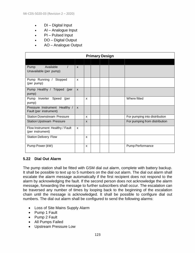
IW-CDS-5020-03 (Revision 2 – 2020)
123
DI – Digital Input
AI – Analogue Input
PI – Pulsed Input
DO – Digital Output
AO – Analogue Output
Primary Design
Signal Name DI AI PI DO AO Comments Pump Available /
Unavailable (per pump)
x
Pump Running / Stopped (per pump)
x
Pump Healthy / Tripped (per
pump)
x
Pump Inverter Speed (per
pump)
x Where fitted
Pressure Instrument Healthy / Fault (per instrument)
x
Station Downstream Pressure x For pumping into distribution
Station Upstream Pressure x For pumping from distribution
Flow Instrument Healthy / Fault (per instrument)
x
Station Delivery Flow x
Pump Power (kW) x Pump Performance
5.22 Dial Out Alarm
The pump station shall be fitted with GSM dial out alarm, complete with battery backup. It shall be possible to text up to 5 numbers on the dial out alarm. The dial out alarm shall escalate the alarm message automatically if the first recipient does not respond to the alarm by acknowledging the fault. If the second person does not acknowledge the alarm message, forwarding the message to further subscribers shall occur. The escalation can be traversed any number of times by looping back to the beginning of the escalation chain until the message is acknowledged. It shall be possible to configure dial out numbers. The dial out alarm shall be configured to send the following alarms:
Loss of Site Mains Supply Alarm
Pump 1 Fault
Pump 2 Fault
All Pumps Failed
Upstream Pressure Low
IW-CDS-5020-03 (Revision 2 – 2020)
124
Downstream Pressure High
Upstream pressure Instrument Fault
Downstream pressure Instrument Fault
Flow rate (intervals to be agreed with Local Water Services staff) 5.23 Operation & Maintenance Manual
The Operation & Maintenance Manual, to be included in the Final Documents (as outlined in Section 1.8.9) is to include at a minimum:
General description of the pump station (i.e. number of houses, size & length of rising main, discharge point etc.)
General safety considerations of working in and near pumping stations
As-build drawings of pump station including showing the route of the water distribtion network and electrical ducts
Commissioning sheets for the pumps and equipment
Blank sheets for ongoing Operation & Maintenance duties.
Panel drawings
Pump curve
Pump O&M manual (including wiring diagram)
Exploded diagram of spare parts for the pump installed
Details of the alarm system including instruction on how to change phone number etc.
IW-CDS-5020-03 (Revision 2 – 2020)
125
Appendix A
Specifications for Boundary Box and Fittings
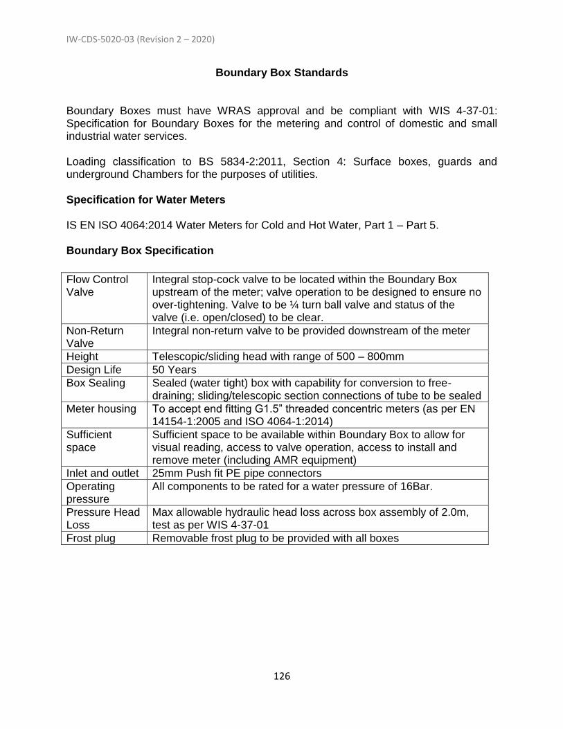
IW-CDS-5020-03 (Revision 2 – 2020)
126
Boundary Box Standards Boundary Boxes must have WRAS approval and be compliant with WIS 4-37-01: Specification for Boundary Boxes for the metering and control of domestic and small industrial water services. Loading classification to BS 5834-2:2011, Section 4: Surface boxes, guards and underground Chambers for the purposes of utilities. Specification for Water Meters IS EN ISO 4064:2014 Water Meters for Cold and Hot Water, Part 1 – Part 5. Boundary Box Specification
Flow Control Valve
Integral stop-cock valve to be located within the Boundary Box upstream of the meter; valve operation to be designed to ensure no over-tightening. Valve to be ¼ turn ball valve and status of the valve (i.e. open/closed) to be clear.
Non-Return Valve
Integral non-return valve to be provided downstream of the meter
Height Telescopic/sliding head with range of 500 – 800mm
Design Life 50 Years
Box Sealing Sealed (water tight) box with capability for conversion to free-draining; sliding/telescopic section connections of tube to be sealed
Meter housing To accept end fitting G1.5” threaded concentric meters (as per EN 14154-1:2005 and ISO 4064-1:2014)
Sufficient space
Sufficient space to be available within Boundary Box to allow for visual reading, access to valve operation, access to install and remove meter (including AMR equipment)
Inlet and outlet 25mm Push fit PE pipe connectors
Operating pressure
All components to be rated for a water pressure of 16Bar.
Pressure Head Loss
Max allowable hydraulic head loss across box assembly of 2.0m, test as per WIS 4-37-01
Frost plug Removable frost plug to be provided with all boxes
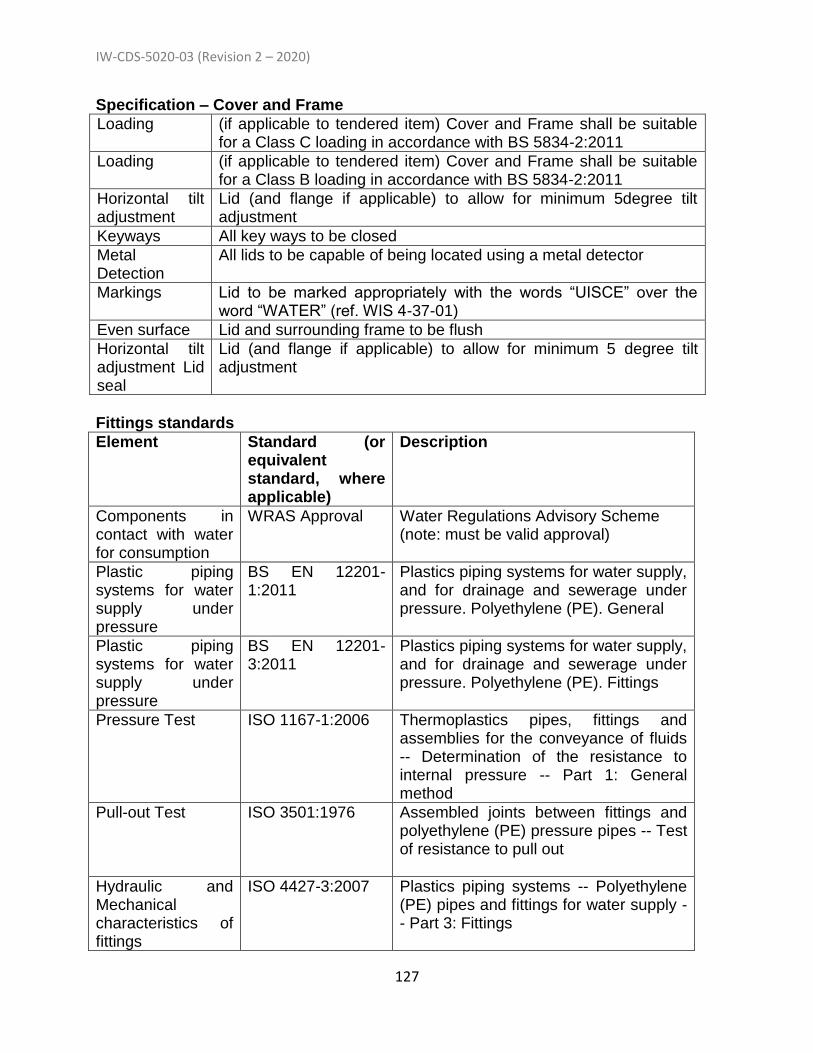
IW-CDS-5020-03 (Revision 2 – 2020)
127
Specification – Cover and Frame
Loading (if applicable to tendered item) Cover and Frame shall be suitable for a Class C loading in accordance with BS 5834-2:2011
Loading (if applicable to tendered item) Cover and Frame shall be suitable for a Class B loading in accordance with BS 5834-2:2011
Horizontal tilt adjustment
Lid (and flange if applicable) to allow for minimum 5degree tilt adjustment
Keyways All key ways to be closed
Metal Detection
All lids to be capable of being located using a metal detector
Markings Lid to be marked appropriately with the words “UISCE” over the word “WATER” (ref. WIS 4-37-01)
Even surface Lid and surrounding frame to be flush
Horizontal tilt adjustment Lid seal
Lid (and flange if applicable) to allow for minimum 5 degree tilt adjustment
Fittings standards
Element Standard (or equivalent standard, where applicable)
Description
Components in contact with water for consumption
WRAS Approval Water Regulations Advisory Scheme (note: must be valid approval)
Plastic piping systems for water supply under pressure
BS EN 12201-1:2011
Plastics piping systems for water supply, and for drainage and sewerage under pressure. Polyethylene (PE). General
Plastic piping systems for water supply under pressure
BS EN 12201-3:2011
Plastics piping systems for water supply, and for drainage and sewerage under pressure. Polyethylene (PE). Fittings
Pressure Test ISO 1167-1:2006 Thermoplastics pipes, fittings and assemblies for the conveyance of fluids -- Determination of the resistance to internal pressure -- Part 1: General method
Pull-out Test ISO 3501:1976 Assembled joints between fittings and polyethylene (PE) pressure pipes -- Test of resistance to pull out
Hydraulic and Mechanical characteristics of fittings
ISO 4427-3:2007 Plastics piping systems -- Polyethylene (PE) pipes and fittings for water supply -- Part 3: Fittings

IW-CDS-5020-03 (Revision 2 – 2020)
128
Leakproofness under internal pressure (mechanical joints)
ISO 3459:1976 Polyethylene (PE) pressure pipes -- Joints assembled with mechanical fittings -- Internal under-pressure test method and requirement
Leakproofness under internal pressure when subject to bending
ISO 3503:1976 Assembled joints between fittings and polyethylene (PE) pressure pipes -- Test of leakproofness under internal pressure when subjected to bending
Leakproofness under internal pressure (between fittings and PE pressure pipe)
ISO 3458:1976 Assembled joints between fittings and polyethylene (PE) pressure pipes -- Test of leakproofness under internal pressure
Tapered Pipe Threads (if being supplied)
ISO 7/1:1994 Pipe threads where pressure-tight joints are made on the threads -- Part 1: Dimensions, tolerances and designation
Parallel Pipe Threads (if being supplied)
ISO 228/1:2003 Pipe threads where pressure-tight joints are not made on the threads. Dimensions, tolerances and designation
Where new pipe is required to complete an installation it is to be 25mm dia. MDPE (Colour Blue)

IW-CDS-5020-03 (Revision 2 – 2020)
129
Appendix B
Standards referenced in the Water Code of Practice

IW-CDS-5020-03 (Revision 2 – 2020)
130
Standard Type: IS Irish Standard BS British Standard IS EN European Standard adopted as an Irish Standard BS EN European Standard adopted as a British Standard WIS UK Water Industry Specification IGN Information and Guidance Notes SR Irish National Guidance Standard Recommendation
Standard Type
Standard Number
Title
BS 750 Specification for Underground Fire Hydrants and Surface Box Frames and Covers (See also BS EN 1074 Part 6).
IS EN 14339 Underground Fire Hydrants
IS EN 124 Gully Tops, Manhole Tops for Vehicular and Pedestrian Areas – Design Requirements, Type, Testing, Marking, Quality Levels (See also BS EN 124)
IS 261 Water Services Road Furniture – Requirements for Cast Iron Cover and Frames
IS EN 752 Drain and Sewer Systems Outside Buildings (See also BS EN 752 2008 – Drain and Sewer Systems Outside Buildings)
IS EN 805 Water Supply - Requirements for Systems and Components Outside Buildings
IS EN 206 Concrete Specification, Performance, Production and Conformity (See also BS EN 206:2013)
BS PAS 27 Unplasticized Poly Vinyl-Chloride Alloy (PVC-A) Pipes and Bends for Water Under Pressure
IS EN 545 Ductile Iron Pipes, Fittings, Accessories and their Joints for Water Pipelines. (See also BS EN 545)
BS 5163 Valves for Waterworks Purposes, Part 1: Predominantly Key Operated Cast Iron Gate Valves Code of Practice
IS EN 1074 Valves for Water Supply – Fitness for Purpose and Appropriate Specification Tests Part 1 – General Requirements Part 2 – Isolating Valves Part 3 – Check Valves Part 4 Air Valves Part 5 Control Valves Part 6 - Hydrants
BS EN 593 Industrial Valves – Metallic Butterfly Valves.
BS EN 1561 Grey Cast Iron
BS EN 1092 Flanges and Their Joints – Circular Flanges for Pipes, Valves, Fittings and Accessories – PN Designations

IW-CDS-5020-03 (Revision 2 – 2020)
131
Part 1:- Steel Flanges Part 2:- Ductile Iron Flanges
BS 4449 Steel for Reinforcement of Concrete – Bar, Coil and De-coiled Product - Specification
BS 3251 Indicator Plates for Hydrants and Emergency Water Supplies
IS 162 Concrete Marker Posts applicable to precast concrete posts for use in marking the locations of hydrants, air valves and sluice valves
BS 381C Specification for Colour for Identification, Colour and Special Purposes
BS 6076 Specification for Polymetric Film for Use as a Protective Sleeve for Buried Iron Pipes and Fittings
WIS 4-08-02 Specification for Pipe Bedding and Side-fill Materials for Buried Pipelines (IGN 4-08-01 Information and Guidance Note on Bedding and Side-fill Materials for Buried Pipelines.
IS EN 12620 Aggregate for Concrete (See also SR16 – Guidance for Use of IS EN 12620)
SR 16 Guidance for the Use of IS EN 12620:2002
WIS 4-22-02 Specification for Ferrules (Tappings and Tees) and Ferrule Straps for Underground Use
BS 5433 Specification for Underground Stop Valves for Water Services.
BS 5834 Surface Boxes, Guards and Underground Chambers for the Purposes of Utilities – Part 2 - Specification for Surface Boxes.
BS 5834 Surface Boxes, Guards and Underground Chambers for the Purposes of Utilities – Part 4 - Specification for Utility Chambers
IS EN 12201 Plastic Piping Systems for Water Supply Systems and Drainage and Sewerage Under Pressure. Part 1:- General, Part 2:- Pipes, Part 3:- Fittings, Part 4:- Valves for Water Supply systems, Part 5: Fitness for Purpose of the System.
IS EN 771 Specification for Masonry Units Part 2:- Calcium Silicate masonry Units Part 3:- Aggregate Concrete masonry Units (Dense and Lightweight Aggregate)
IS EN 1717 Protection Against Pollution of Potable Water in Water Installations and General Requirements of Devices to Prevent Pollution and Backflow
BS EN 12613 Plastic Warning Devices for Underground Cables and Pipelines with Visual Characteristics
WIS 4-32-08 Specification for Fusion Jointing of Polyethylene Pressure

IW-CDS-5020-03 (Revision 2 – 2020)
132
Pipeline Systems Using PE80 and PE100 Materials
IGN 4-32-18 The Choice of pressure rating for Polyethylene Pipe Systems for Water Supply and Sewerage Duties
WIS 4-32-19 Polyethylene Pressure Pipe Systems with an Aluminium Barrier Layer for Potable Water Supply in Contaminated Land – Size 25 to 630mm
IGN 4-01-03 Pressure Testing of Pressure Pipes and Fittings for use by Public Water Supplies.
IS EN ISO
4064 Water Meters for Cold and Hot Water Part 1: Metrological and Technical requirements Part 2: Test Methods Part 3: Test Report Format Part 4: Non-Metrological Requirements not covered by ISO 4064-1 Part 5: Installation Requirements
WIS 4-37-01 Specification for Boundary Boxes for Metering and Control of Domestic and Small Industrial Water Services
IS EN ISO
1167 Thermoplastic Pipes and fittings for Conveyance for Fluids – Determination of Resistance to Internal Pressure Part 1: General Methods Part 2: Preparation of Pipe Test Pieces Part 3: Preparation of Components Part 4 Preparation of Assemblies
ISO 3501 Assembled Joints Between Fittings and Polyethylene (PE) Pressure Pipes – Test Resistance Under Constant Longitudinal Force
ISO 4427 Plastic Piping Systems – Polyethylene (PE) Pipes and Fittings for Water Supply Part 1: General Part 2: Pipes Part 3: Fittings Part 5: Fitness for Purpose of the System
ISO 3459 Polyethylene (PE) Pressure Pipes – Joint Assembled with Mechanical Fittings – Internal Under Pressure Test Method and Requirement
ISO 3458 Assembled Joints Between Fittings and Polyethylene (PE) Pressure Pipes – Test of Leak Proofness Under Internal Pressure
ISO 7/1 Pipe Threads Where Pressure-Tight Joints Are Made on Threads – Part 1: Dimensions, Tolerances and Designations
BS EN ISO
228/1 Pipe Threads Where Pressure-Tight Joints Are Not Made on Threads – Part 1: Dimensions, Tolerances and Designations
IS EN 622 Fibreboard Specification Part 1 – General Requirements Part 2 – Requirements for Hardboards Part 3 – Requirements for Medium Boards

IW-CDS-5020-03 (Revision 2 – 2020)
133
Part 4 – Requirements for Soft Boards Part 5 – Requirements for Dry Process Boards (MDF)
BS EN 1561 Founding – Grey Cast Irons
IS EN 1917 Concrete Manholes and Inspection Chambers, Unreinforced, Steel Fibre and Reinforced (See also BS EN 1917)
IS EN 13242 Aggregates for Unbound and Hydraulically Bound Material for Use in Civil Engineering Works and Road Construction
BS 4660 Thermoplastics Ancillary Fittings of Nominal Size 110 to 160 for Below Ground Gravity Drainage and Sewerage
BS EN 1401 Plastics Piping systems for Non-Pressure Underground Drainage and Sewerage – Unplasticized Poly (Vinyl – Chloride) (PVC-U) – Part 1 – Specification for Pipes, Fittings and the System
BS 476 Fire Tests for Building Materials and Structures
BS 4800 Schedule of Paint Colours for Building Purposes
WIS 4-52-01 Specification for Anti-corrosion (Barrier) Coatings
WIS 4-52-03 Specification for Anti-corrosion Coatings on Threaded Fasteners
IS EN 14525 Flanged Adaptors
IS EN 14901 Ductile Iron Pipes, Fittings and Accessories – Epoxy coating (heavy duty) of ductile iron fittings and accessories – requirements and test methods
IS EN 1563 Founding. Spheroidal Graphite Cast Iron
EN 681-1 Elestomeric Seals. Material Requirements for Pipe Joint Seals Used in Water and Drainage Applications
BS 4190 ISO Metric Black Hexagon Bolts, Screws and Nuts. Specification.
BS 4320 Specification for Metal Washers for General Engineering Purposes. Metric Series
BS 7874 Method of Test for Microbiological Deterioration of Elastomeric Seals for Joints in Pipework and Pipelines.
BS 5837 Trees in Relation to Design, Demolition and Construction - Recommendations
ISO 16422 Pipes and Joints made of Oriented Unplasticised Polyviinal Chloride (PVCO) for the conveyancing of water under pressure
IS 328 Gas transmission pipelines and pipeline installations - .
Edition 4
IS 329 As distribution mains.
IS 370 Colour code for buried plastics piping.
BS 5834 Surface boxes, guards and underground chambers for the purposes of utilities. Specification for guards and plinths.
BS 6076 Specification for polymeric film for use as a protective

IW-CDS-5020-03 (Revision 2 – 2020)
134
sleeving for buried iron pipes and fittings (for site and factory application).
BS 8558 Guide to the design, installation, testing and maintenance of services supplying water for domestic use within buildings and their curtilages. Complementary guidance to BS EN 806.
BS 6920 Suitability of non-metallic materials and products for use in contact with water intended for human consumption with regard to their effect on the quality of the water. Methods of test. Samples for testing.
BS 8545 Trees: from nursery to independence in the landscape. Recommendations.
IS EN 806 Specifications for Installations Inside Buildings Conveying Water for Human Consumption.
IS EN 206 Concrete - specification, performance, production and
conformity
IS EN 12842 Ductile iron fittings for PVC-U or PE piping systems - Requirements and test methods.
IS EN 1092 Flanges and their joints. Circular flanges for pipes, valves, fittings and accessories, PN designated. Steel flanges.
IS EN 998-2 Specification for mortar for masonry - Masonry mortar
IS EN 13101 Steps for underground man entry chambers. Requirements, marking, testing and evaluation of conformity.
EN 420 Precast Concrete Manholes.
IS EN 1627 Pedestrian door sets, windows, curtain walling, grilles and shutters - Burglar resistance - Requirements and classification.
IS EN 61386-24 Conduit systems for cable management. Particular
requirements. Conduit systems buried underground
(incorporating corrigendum November 2010).
WIS 4-21-02 Specification for mechanical couplings and repair clamps for iron pipes for the conveyance of cold potable water (underground use) for the size range 40 to 1600mm/1.5 to 48” inclusive.
WIS 4-37-01 Specification for boundary boxes for the metering and control of domestic and small industrial water services.
BS ISO 21307:2017 Plastics pipes and fittings. Butt fusion jointing procedures for polyethylene (PE) pipes and fittings used in the construction of gas and water distribution systems.
BS ISO 12176 Plastics pipes and fittings. Equipment for fusion jointing polyethylene systems. Butt fusion.
IGN 4-32-18 The choice of pressure ratings for polyethylene pipe systems for water supply and sewerage duties.
IGN 4-01-03 Guide to pressure testing of pressure pipes and fittings for use by public water suppliers.
IGN 4-08-01 Bedding and side fill materials for buried pipelines.

IW-CDS-5020-03 (Revision 2 – 2020)
135
ISO 9001 Quality Management Systems - Requirements.
ISO 21307:2013 Plastics pipes and fittings — Butt fusion jointing procedures for polyethylene (PE) pipes and fittings used in the construction of gas and water distribution systems.
ISO 12176 Plastics pipes and fittings — Equipment for fusion jointing polyethylene systems — Part 1: Butt fusion.
ISO 13953 Polyethylene (PE) pipes and fittings — Determination of the tensile strength and failure mode of test pieces from a butt-fused joint.
ISO 13954 Plastics pipes and fittings — Peel de-cohesion test for polyethylene (PE) electrofusion assemblies of nominal outside diameter greater than or equal to 90 mm.
ISO 13955 Plastics pipes and fittings — Crushing de-cohesion test for polyethylene (PE) electrofusion assemblies.
ISO 13956 Plastics pipes and fittings — De-cohesion test of polyethylene (PE) saddle fusion joints — Evaluation of ductility of fusion joint interface by tear test.
ISO 17025 General requirements for the competence of testing and calibration laboratories.
ISO 9960 Draughting instruments with or without graduation — Part 1: Draughting scale rules.
ISO 4064-1:2014
Water meters for cold potable water and hot water — Part 1: Metrological and technical requirements.
IS EN 898-1 Mechanical properties of fasteners made of carbon steel and alloy steel. Bolts, screws and studs with specified property classes. Coarse thread and fine pitch thread.
IS EN 898-2 Mechanical properties of fasteners made of carbon steel and alloy steel. Nuts with specified property classes. Coarse thread and fine pitch thread.
IS EN 3506-1 Mechanical properties of corrosion-resistant stainless steel fasteners. Bolts, screws and studs.
IS EN 3506-2 Mechanical properties of corrosion-resistant stainless steel fasteners. Nuts.
EN 14154-1:2005
Water meters. part 1 General requirements
IS EN 16941-1 On Site Non Potable Water Systems – Part 1, Syatems for the
Use of Rainwater

IW-CDS-5020-03 (Revision 2 – 2020)
136
Appendix C
Amendments Associated with change from Revision 1 (December 2017) to Revision 2 (July 2020)

IW-CDS-5020-03 (Revision 2 – 2020)
137
Amendment Location
Description of Change for Revision 2
General Amendments
The Code of Practice has been amended in a significant number of areas. These amendments are listed below in relation to the location of the amendment (Section, Sub-Section, etc.). There are a number of amendments arising from high level changes and these are referred to a “General Amendments” as opposed to “particular amendments”. A general amendment is applied to align the terminology within the Code of Practice with the terminology used in the Self-lay Connection Agreement where applicable. Examples of this are listed below and examples are as follows:
“development(s)” is changed to “Development(s)” as this is a defined term;
“Customer” has been changed to “Developer”;
A new term of “Water and Wastewater Services Infrastructure” has been included;
A new term of “Self-Lay Works” has been included;
Etc. As a consequence, minor amendments are included in many Sections to reflect new defined terms. It is not deemed necessary to list all of the Sections and Sub-Section affected by the terminology changes as these changes are non material in most instances. Other general amendments relate to the following: - The use of IS 420 and IS EN 1917 as standards for pre-cast
concrete manhole units where these are used in the Works., - An amended specification for the bedding of chamber cover
frames seated with rapid hardening cementitious, epoxy or polyester resin mortar, with a minimum working time of 15 minutes, a minimum compressive strength of 30 N/mm2 and 5 N/mm2 within 3 hours of mixing.
- An amendment specifying the bedding and setting mortar for Class B engineering brick under chamber covers/frames should be of minimum M30 strength mortar to IS EN 998 – Part 2.
- Changes to IW maintenance responsibility, - Standard for compliance of PE Pipe joints revised, - Sampling and testing of PE pipes updated, - Specification for pipe surround and bedding material amended
to reflect IS EN 13242 requirements for 14 to 5mm (d/D 2/14) and 10mm (d/D 4/10),
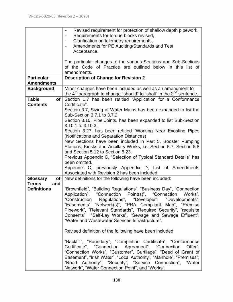
IW-CDS-5020-03 (Revision 2 – 2020)
138
- Revised requirement for protection of shallow depth pipework, - Requirements for torque blocks revised, - Clarification on telemetry requirements, - Amendments for PE Auditing/Standards and Test
Acceptance. The particular changes to the various Sections and Sub-Sections of the Code of Practice are outlined below in this list of amendments.
Particular Amendments
Description of Change for Revision 2
Background Minor changes have been included as well as an amendment to the 4th paragraph to change “should” to “shall” in the 2nd sentence.
Table of Contents
Section 1.7 has been retitled “Application for a Conformance Certificate”. Section 3.7, Sizing of Water Mains has been expanded to list the Sub-Section 3.7.1 to 3.7.2 Section 3.10, Pipe Joints, has been expanded to list Sub-Section 3.10.1 to 3.10.3. Section 3.27, has been retitled “Working Near Exosting Pipes (Notifications and Separation Distances) New Sections have been included in Part 5, Booster Pumping Stations, Kiosks and Ancillary Works, i.e. Section 5.7, Section 5.8 and Section 5.12 to Section 5.23. Previous Appendix C, “Selection of Typical Standard Details” has been omitted. Appendix C, previously Appendix D, List of Amendments Associated with Revision 2 has been included.
Glossary of Terms and Definitions
New definitions for the following have been included: “Brownfield”, “Building Regulations”, “Business Day”, “Connection Application”, “Connection Point(s)”, “Connection Works”, “Construction Regulations”, “Developer”, “Developments”, “Easements” “Network(s)”, “PRA Compliant Map”, “Premise Pipework”, “Relevant Standards”, “Required Security”, “requisite Consents” “Self-Lay Works”, “Sewage and Sewage Effluent”, “Water and Wastewater Services Infrastructure”, Revised definition of the following have been included: “Backfill”, “Boundary”, “Completion Certificate”, “Conformance Certificate”, “Connection Agreement”, “Connection Offer”, “Connection Works”, “Customer”, Curtilage”, “Deed of Grant of Easement”, “Irish Water”, “Local Authority”, “Manhole”, “Premises”, “Road Authority”, “Security”, “Service Connection”, “Water Network”, “Water Connection Point”, and “Works”.

IW-CDS-5020-03 (Revision 2 – 2020)
139
Section 1.1 The 1st sentence has been amended to outline what the “Works” covers. Two new paragraphs have been included at the end of the Section.
Section 1.2 Minor changes made to the 2nd paragraph making reference to “Bord Gais” and the “Commission of Regulation of Utilities”.
Section 1.3 Sub-Section 1.3.2 amended to indicate that Irish Water’s contractor undertakes the work,
Section 1.4 Amendment to Section 1.4.1 to clarify that a Pre-connection Enquiry is mandatory for Developments using the planning procedures of the Strategic Housing Development Regulations.
Section 1.5 The 3rd paragraph has been amended to outline that the water quality tests have to comply with the parametric standards laid down in Statutory Instrument 122 of 2014, European Union (Drinking Water) Regulations 2014. The last sentence of this paragraph outlines a relaxation of the 14-day period for retesting.
Section 1.6 The 3rd paragraph has been expanded to indicate that Irish Water may require remediation work on the distribution system for the protection of public health and/or water conservation. A new paragraph has been added to indicate that the responsibility for the maintenance of the water supply service connection to Premises is outlined on the Irish Water website, www.water.ie and in the Pipe Maintenance Responsibility Diagrams included therein.
Section 1.7 Amendments as follows: - 2nd paragraph has been amended to refer to the “Quality
Assurance Field Inspection Requirements” Manual. - Additional paragraph included after Sub-Section 1.7.2 to
indicate that the issuing of the Conformance Certificate marks the commencement of the Defects Liability Period.
- Sub-Sections 1.7.3, 1.7.4 and 1.7.5 amended to require the Chartered Engineer confirmation to be provided in writing.
- Minor amendment to Sub-Section 1.7.7. - Sub-section 1.7.9 to expand the information to be included in
Operation and Maintenance Manual of Pump Stations. - Minor amendment to Sub-Section 1.7.10. - Sub-Section 1.7.15 amended to revise scale of drawings and
CAD compatibility requirements. - Sub-Section 1.7.15.5 amended to include the horizontal and
vertical scale for As-Constructed drawings. .
Section 1.8 The 1st paragraph expanded to indicate that the minor corrections shall be addressed by the Developer within a reasonable timeframe before the connection is completed.
Section 1.9 Amended as follows: - New sentence included at end of 1st paragraph indication that
Irish Water will undertake investigation of the Works during the Defects Liability Period.
- Clarification provided in second paragraph in relation to

IW-CDS-5020-03 (Revision 2 – 2020)
140
development of subsequent phases of an overall Development.
Section 1.10 Minor amendments to reflect new defined terms. Last paragraph amended to indicate that the Developer is responsible for the operation and maintenance of the infrastructure until the end of the Defects Liability Period.
Section 1.11 Minor amendments to reflect new defined terms.
Section 1.12 Minor amendments to reflect new defined terms. The last paragraph amended to make reference to Sub-Sections 1.5.6 to Sub-Section 1.5.8.
Section 1.13 Minor amendments to reflect new defined terms.
Section 1.14 Minor amendments to reflect new defined terms. A new 2nd paragraph is included to outline that additional surveys and inspection are to be undertaken to locate defects at the cost of the Developer.
Section 1.15 Minor amendments to reflect new defined terms.
Section 1.17 Minor amendments to reflect new defined terms. The 6th paragraph amended to indicate that Irish Water will provide the make and model for any meter to be provided on a fire main. Th last paragraph amended to indicate that the location of fire hydrants is to ensure fire fighting can be carried out within the Development. .
Section 1.19 The 3rd paragraph has been amended in respect of the use of newly developed products and indicating that Irish water is not obliged to accept such products.
Section 1.22 The 1st paragraph amended to indicate that a Developer who requires a water supply connection during the Development construction period for temporary site office accommodation and general construction activities shall apply to Irish Water for the provision of this temporary water supply.
Section 1.23 The 1st paragraph amended to outline requirements for any pipework that is installed to facilitate providing a future connection to contiguous undeveloped sites.
Section 2.1 Amendment of the 2nd paragraph to indicate that the Developer’s designer is to be competent.
Section 2.2 Amendment of the 2nd paragraph to in relation to the continued responsibility of the Developer’s designer and the retention of Professional Indemnity Insurance for a period of 6 years after the issue of the Completion Certificate.
Section 2.3 Amended as follows: - Sub-Section 2.3.13 expanded to require the submission of
Fire Authority approvals for the development. - Sub-Section 2.3.15 expanded to required identification of the
manufacturers of pipelines and accessory materials. - A new Sub-Section 2.3.16 included to require the submission
of certification of fittings and materials used in the Works. - Section 2.3.18 expanded to require a report on separation

IW-CDS-5020-03 (Revision 2 – 2020)
141
distances. - A new Sub-Section 2.3.21 included to require the submission
of a Preliminary Health and Safety Plan. - New Sub-Section 2.3.24 included to require the submission of
information where construction of the Works is to be carried out on made ground, engineered ground or in fill zones and the submission of geotechnical reports and the submission of method statements for the construction of the Works.
Section 2.4 Amended as follows: - The 3rd paragraph has been amended to indicate revised
arrangements for the submission of drawings. - Sub-section 2.4.2 expanded to require the submission of an
overall development plan layout of the units intended to be constructed and delivered in phases indicating phase lines and control breaks.
- Sub-Section 2.4.9 expanded to require the submission of information of above ground structures that are to be vested by Irish Water
- Sub-Section 2.4.11 expanded to require the submission of details of existing services crossing the Works and details of thrust blocks, etc.
- Sub-Section 2.4.13 expanded to require the submission of details made ground, engineered ground or fill zones.
- Sub-Section 2.4.14 expanded to require the integrated utility layout pan to comply with required separation distances. .
- The 7th paragraph has been expanded to require the submission of manufacturer’s data sheets and certificates for the long with the schedule of materials required for the proposed Works. .
- A new 9th paragraph is included to require that the design submission to include specific information of any business (non-domestic) customers that are to be served as well as any other pertinent information.
Section 2.5 The last paragraph is amended to require on site flow and pressure verification of the hydraulic model results shall be used to confirm this and Irish Water shall be provided with an opportunity to observe these verifications.
Section 2.6 Amended as follows: - Sub-Section 2.6.7 has been expanded to outline the
requirement for the provision of a sluice valve and a bypass complete with a meter to measure night-flows in developments that are not fitted with bulk meter.
- Sub-Section 2.6.12 has been expanded to indicate that break tanks and booster pumps may be required for taller buildings as necessary to augment normal background supply pressure
Section 3.1 The 1st paragraph is expanded to require compliance with the

IW-CDS-5020-03 (Revision 2 – 2020)
142
Standard Details as well as Codes of Practice.
Section 3.2 The word “should” has been replaced with “shall” in the 2nd and 3rd paragraphs.
Section 3.3 Amended as follows: - A new 1st paragraph has been expanded to require the
Developer to have an auditable system in place to trace materials from manufacture, specification, purchase and through to delivery and their use in the permanent Works on site.
- A new Sub-Section 3.3.3 is included to indicate that other material to those listed in 3.3.1 and 3.3.2 (DWI and WRAS) may be accepted by Irish Water provided that they have certification equivalence for use in contact with water intended for human consumption from other EU States from nationally recognised Certification Bodies, subject to review by Irish Water.
Section 3.4 Amended as follows: - Sub-Section 3.4.4 amended to outline protection measures for
pipes installed at shallow depths, i.e., the provision of reinforced concrete protection slab.
- New Sub-Section 3.4.8 requiring the Works to be watertight in accordance with the requirement of Sub-Clause 4.10.3.
- New Sub-Clause 3.4.9 requiring that no trees or large shrubs be located over the Works.
Section 3.5 Amended as follows: - Sub-Section 3.5.1 expanded to require the infrastructure layout
to be a simple and short as possible. - Sub-Section 3.5.2 expanded to include location of infrastructure
is separated from trees, shrubs, also. - Sub-Section 3.5.3 expanded to include renewal, replacement
and upgrading. - Sub-Section 3.5.4 expanded to include renewal, replacement
and upgrading. - Sub-Clause 3.5.5 expanded to indicate that the infrastructure
can be safely accessed. - Sub-Section 3.5.6 expanded to require service connection
lengths to be minimised. - Sub-Section 3.5.7 clarified in relation to a “single supply
network”. - Sub-Section 3.5.8 is expanded to indicate that the water main
may be located on roadways is there are space constraints on footpaths. .
- Sub-Section 3.5.13 has been expanded to indicate that the loop main is to be of the same internal diameter as the branch main to which it is connected. .
- Sub-Section 3.5.16 amended to qualify that the minimum size
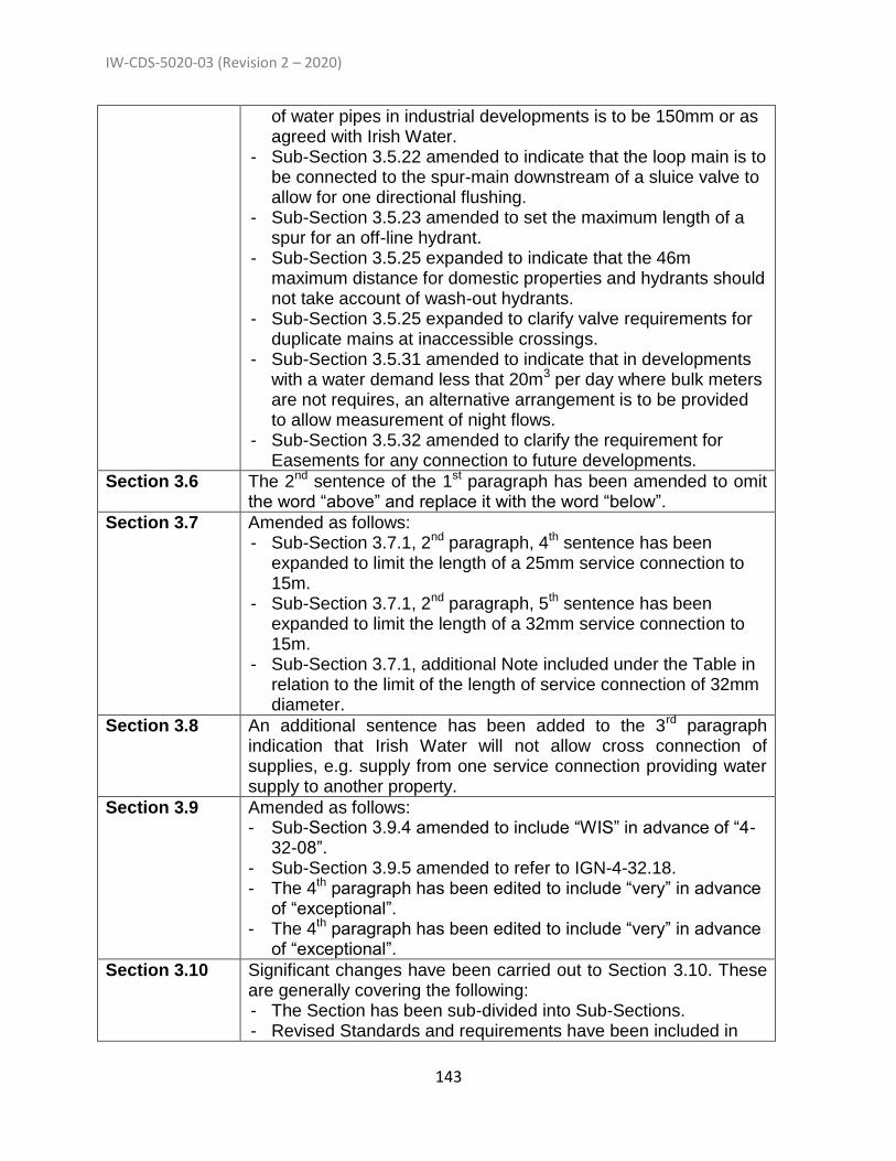
IW-CDS-5020-03 (Revision 2 – 2020)
143
of water pipes in industrial developments is to be 150mm or as agreed with Irish Water.
- Sub-Section 3.5.22 amended to indicate that the loop main is to be connected to the spur-main downstream of a sluice valve to allow for one directional flushing.
- Sub-Section 3.5.23 amended to set the maximum length of a spur for an off-line hydrant.
- Sub-Section 3.5.25 expanded to indicate that the 46m maximum distance for domestic properties and hydrants should not take account of wash-out hydrants.
- Sub-Section 3.5.25 expanded to clarify valve requirements for duplicate mains at inaccessible crossings.
- Sub-Section 3.5.31 amended to indicate that in developments with a water demand less that 20m3 per day where bulk meters are not requires, an alternative arrangement is to be provided to allow measurement of night flows.
- Sub-Section 3.5.32 amended to clarify the requirement for Easements for any connection to future developments.
Section 3.6 The 2nd sentence of the 1st paragraph has been amended to omit the word “above” and replace it with the word “below”.
Section 3.7 Amended as follows: - Sub-Section 3.7.1, 2nd paragraph, 4th sentence has been
expanded to limit the length of a 25mm service connection to 15m.
- Sub-Section 3.7.1, 2nd paragraph, 5th sentence has been expanded to limit the length of a 32mm service connection to 15m.
- Sub-Section 3.7.1, additional Note included under the Table in relation to the limit of the length of service connection of 32mm diameter.
Section 3.8 An additional sentence has been added to the 3rd paragraph indication that Irish Water will not allow cross connection of supplies, e.g. supply from one service connection providing water supply to another property.
Section 3.9 Amended as follows: - Sub-Section 3.9.4 amended to include “WIS” in advance of “4-
32-08”. - Sub-Section 3.9.5 amended to refer to IGN-4-32.18. - The 4th paragraph has been edited to include “very” in advance
of “exceptional”. - The 4th paragraph has been edited to include “very” in advance
of “exceptional”.
Section 3.10 Significant changes have been carried out to Section 3.10. These are generally covering the following: - The Section has been sub-divided into Sub-Sections. - Revised Standards and requirements have been included in

IW-CDS-5020-03 (Revision 2 – 2020)
144
Sub-Section 3.10.1 for fusion welding, welding equipment, etc. - Revised requirement are included in Sub-Section 3.10.2 for
jointing of polyethylene pipes. - Revised requirement are included in Sub-Section 3.10.3 for
auditing and testing of polyethylene pipe joints. - Additional requirement are included in Sub-Section 3.10.3 for
jointing of polyethylene pipe coils.
Section 3.11 Amended as follows: - The 1st sentence of the 2nd paragraph has been expanded to
require the depth of cover in road verges to be 900mm. - The 4th sentence of the 2nd paragraph has been amended to
include “depth of” ahead of “cover” and “shall” is included to replace “should”.
- A 3rd paragraph has bene included to outline pipe protection measures for water mains that are not installed with the required depth of cover.
Section 3.14 Amended as follows: - The 3rd paragraph has been expanded to outline requirements
for the location of Boundary Boxes. - The 6th paragraph has been expanded to outlined requirements
relating to manifold Boundary Box systems for water service connections for multi unit low rise buildings.
Section 3.15 Amended as follows: Sub-Section 3.15.1 has been amended as follows: - The original first paragraph has been split into a number of
paragraphs and amendments included as outlined below. - The 1st paragraph (new) outlines clarifications on meter types
installed in Boundary Boxes and Chambers. It also outlines that the Developer is to install a spool piece in the location to be occupied by meters and that Irish Water will install a meter in the spool piece location following connection.
- The 3rd paragraph (new) outlines a flow measurement system for Developments that have a demand less than 20m3 per day and are not fitted with bulk meters.
- A new 5th paragraph has been included to outline the requirement to provide meter Chambers and to indicate that Irish Water will install the meters and, where required, strainers in the chambers in lieu of spool pieces installed by the Developer.
- A new 6th paragraph has been included to outline metering requirements for multi unit residential and commercial developments.
Sub-Section 3.15.2 has been amended as follows: - A new 2nd paragraph has been included to outline metering
requirements for low-rise and high-rise multi unit developments. Sub-Section 3.15.3 has been expanded as follows:

IW-CDS-5020-03 (Revision 2 – 2020)
145
- An additional sentence has been included to indicate that Developers are to provide meters chambers into which Irish Water will subsequently fit a meter.
Sub-Section 3.15.4 has been amended as follows: - The 2nd paragraph has bene expanded to indicate that a
hydrant is only required where an electromagnetic meter is being installed.
- The 3rd paragraph has been expanded to indicate that Irish Water will advise if a strainer is required for mechanical meters.
- The 4th paragraph is expanded to indicate when a bypass is required for a meter.
- The 6th paragraph is expanded to indicate when mechnical meters will be provided for housing developments (40 – 249 units) and when non-mechanical (electromagnetic) meters will be provided (250 units and above). It is also indicated that telemetry system will be located in an adjoining kiosk for all non-mechanical meters.
- The 7th paragraph is expanded to outline kiosk requirements for meters.
- The 8th paragraph has been expanded to outline kiosk requirements for non-mechanical meters.
- The 9th paragraph has bene expanded to outline that a night flow meter system is required in developments of 20m3 demand where bulk meters are not provided.
Section 3.16 Amended as follows: Sub-Section 3.16.2 has been amended as follows: - The 3rd paragraph has been amended to set out the maximum
and minimum separation distances between the stem cap of a sluice valve and ground level.
- The 4th paragraph has been expanded to indicate that the direction of closing of the valve is to be included in the valve marker plate.
Sub-Section 3.16.5 has been amended as follows: - The 1st paragraph has been expanded to indicate that the
hydrant outlet type provided is to be to the requirements of the Fire Authority in the area.
- The 4th and 6th paragraphs have been amended to exclude the use of electro-fusion saddle for the 80mm flanged branch connections for hydrants.
- The 5th paragraph has been expanded to set the maximum length of a spur for an off-line hydrant.
- A new 7th paragraph has bene included to allow the use of polyethylene pipework for the length of a spur for an off-line hydrant.
- The last paragraph has been corrected to include “200mm” instead of “200m”.

IW-CDS-5020-03 (Revision 2 – 2020)
146
Sub-Section 3.16.6 has been amended as follows: - The 5th paragraph has been expanded to set the maximum
length of a spur for an off-line hydrant. - The 6th paragraphs have been amended to exclude the use of
electro-fusion saddle for the 80mm flanged branch connections for air valves.
- A new 7th paragraph has bene included to allow the use of polyethylene pipework for the length of a spur for an off-line hydrant.
Sub-Section 3.16.7 has been amended as follows: - The 3rd paragraph is corrected to refer to “WIS 4-52-03” rather
than “WIS 5-52-03”. - The 5th and 6th paragraphs are amended to indicate that flange
adaptors for polyethylene pipes shall be designed for Type 1 end restraint to IS EN 12842 and IS EN 14525.
Section 3.18 Amended as follows: - The 1st paragraph is amended to outline chamber and floor slab
sizes for sluice valve and hydrant chambers. - New 2ndand 3rd paragraphs are included to show reduced
sluice valve and hydrant chamber sizes in non-trafficked areas. - A new 4th paragraph is included outlining the chamber size
required for air valve chambers. - The 5th paragraph has been expanded to outline the
construction materials for chambers. - The 6th paragraph has been expanded to include a
specification for mortar for blockwork chambers. - The 7th paragraph is expanded to specify the concrete strength
for chamber bases and to also outline dimensions of the bas for different locations and construction methods. It is also indicated that free draining granular material is required beneath the drain hole in the base slab to allow free drainage of liquid from the chamber.
- The 8th paragraph calls up the TII Specification for Roadworks. - The 9th paragraph has bene amended to call up applicable
Standards for concrete and aggregate in the base slab and to indicate the cover required for rebar.
- The 10th paragraph has been expanded to indicate that the chamber covers are to be set flush with the finished road surface.
- The 11th paragraph is expanded to indicate that all chamber cover/frames to be bedded with rapid hardening cementitious, epoxy or polyester resin mortar, with a minimum working time of 15 minutes, a minimum compressive strength of 30 N/mm2 and 5 N/mm2 within 3 hours of mixing. In addition it is required that chambers cover/frames to be seated on Class B engineering brick in minimum M30 strength mortar to IS EN

IW-CDS-5020-03 (Revision 2 – 2020)
147
998 – Part 2.
Section 3.19 Amended as follows: - The 1st paragraph has been expanded to outline chamber sizes
for different meter dimensions. - The 2nd paragraph has been expanded to clarify when separate
strainer chambers are required and the requirement for the provision of an appropriately sized spool piece in lieu of the strainer, which will be removed and replaced by Irish Water when the strainer is fitted.
- The 5th paragraph has been expanded to indicate that the chamber should be sized to accommodate a data logger if a separate kiosk is not provided.
- The 7th paragraph is expanded to indicate that all chamber cover/frames to be bedded with rapid hardening cementitious, epoxy or polyester resin mortar, with a minimum working time of 15 minutes, a minimum compressive strength of 30 N/mm2 and 5 N/mm2 within 3 hours of mixing. In addition it is required that chambers cover/frames to be seated on Class B engineering brick in minimum M30 strength mortar to IS EN 998 – Part 2.
- A new 8th paragraph is included outlining the requirement for the provision of spool pieces in meter chambers.
- The 9th paragraph has been expanded to indicate the size requirements for valve and hydrant chambers that are provided in association with meter chambers.
Section 3.20 Amended as follows: - The 6th paragraph has been expanded to indicate that all
chamber cover/frames to be bedded with rapid hardening cementitious, epoxy or polyester resin mortar, with a minimum working time of 15 minutes, a minimum compressive strength of 30 N/mm2 and 5 N/mm2 within 3 hours of mixing. In addition it is required that chambers cover/frames to be seated on Class B engineering brick in minimum M30 strength mortar to IS EN 998 – Part 2.
- The last paragraph is expanded to give requirements for small sized PRV and PSV chambers.
Section 3.21 Amended as follows: - The 2nd paragraph is amended to exclude BS 5911 and replace
it with IS 420. The grade of concrete in the concrete surround has been changed to C20/25.
- The 3rd paragraph is amended to exclude BS 5911 and replace it with IS 420. The dimensions of the roof opening have been revised to 600mm by 600mm or 600mm diameter.
- The 5th paragraph has been expanded to indicate that all chamber cover/frames to be bedded with rapid hardening cementitious, epoxy or polyester resin mortar, with a minimum

IW-CDS-5020-03 (Revision 2 – 2020)
148
working time of 15 minutes, a minimum compressive strength of 30 N/mm2 and 5 N/mm2 within 3 hours of mixing. In addition it is required that chambers cover/frames to be seated on Class B engineering brick in minimum M30 strength mortar to IS EN 998 – Part 2.
Section 3.23 Amended as follows: - The 2nd paragraph is amended to indicate that “Hydrant”
marker plates are to comply with BS 3251. - The last paragraph has been expanded to indicate that plastic
marker posts and plastic indicator plates shall not be provided under any circumstance.
Section 3.26 The acronyms in the first paragraph are expanded. The last paragraph is expanded to indicate that Irish water does not favour planting over its infrastructure.
Section 3.27 Amended as follows: - The title of the section has been amended to “Working Near
Existing Pipes (Notifications and Separation Distances” - 1st paragraph amended to indicate that works in the vicinity of
Irish Water assets of 400mm diameter and more require written agreement from the utility prior to undertaking the work.
- 2nd paragraph amended to limit the application of Sub-Section 3.27.1 to 3.27.8 to situations where the asset is not exceeding 1.5m deep.
- 3rd paragraph amended to require specific written agreement in relation to assets greater than 1.5m deep or where the separation distances are less than set out in Sub-Section 3.27.1 to 3.27.8.
- A new paragraph (4th paragraph) is included to require minimum separation distances as outlined in Section 3.5.18 and Section 3.6.
- Sub-Section 3.27.9 to Sub-Section 3.27.11 amended to include “pipe” rather than “main”.
Section 3.28 Amended as follows: - The 1st paragraph has been amended to indicate that only
indirect plumbing systems should be provided in internal water distributions systems i.e. all appliances shall be plumbed from a cold-water storage tank and supplied by gravity. The benefits of such indirect systems are identified as ensuring that adequate storage capacity is available to serve all appliances within the Premises.
- More guideline water storage volume breakdown is provided for commercial buildings such as restaurants and hotels.
Section 3.29 The 3rd paragraph has been amended to indicate that pipework connected to or from rainwater harvesting systems shall be clearly labelled in accordance with the requirements of EN 16941-1 to avoid misconnection or accidental consumption of non-potable

IW-CDS-5020-03 (Revision 2 – 2020)
149
water.
Section 4.1 Amended as follows: - The 3rd paragraph is amended to call in the requirements of the
Code of Practice. - The 3rd paragraph is expanded. Item (f) is included requiring
protection of the environment. - The word “should” has been replaced by the word “shall” in the
4th, 5th and 6th paragraphs. - The term “leak tight” is explained as passing the requirement of
Section 4.10, Testing and Commissioning. - A new last paragraph has been included indicating that the
Developer shall comply with the requirements of Section 1.5, relating to protection of water quality, and Section 1.12, relating to hygiene requirements, during the construction and commissioning of the Works.
Section 4.2 The 4th paragraph is expanded to require pipes and fittings to be kept clear of fuel oils and any material that might contaminate the material.
Section 4.3 Expanded to require the use of trial holes to locate existing services.
Section 4.5 Transport Infrastructure Ireland is nominated instead of National Roads Authority.
Clause 4.6 Amended as follows: - The 1st sentence of the 3rd paragraph has been amended to
replace “The blocks” with “Anchor and support blocks”. - The 3rd sentence of the 3rd paragraph is amended to indicate
that thrust blocks are required for bends of 11.25 deg. and greater.
- The last sentence of the 3rd paragraph has bene expanded to indicate that compressible filler board and plastic sheeting is required around polyethylene pipes cast against the concrete of thrust and anchor blocks.
- The 4th paragraph is clarified in relation to the provision of torque blocks.
- The 6th paragraph is clarified in relation to the provision of information by the Developer when specialised pipe support systems are proposed.
- The last paragraph is amended to outline that fully integrated PE pipe systems may not require anchorage supports. It is further indicated that where supports are required, compressible filler board, in accordance with the provisions of IS EN 622, Part 1 to Part 4, wrapped in plastic sheeting having a composition in accordance with BS 6076, shall be provided for protection between the concrete and the polyethylene pipe.
Section 4.8 Amended as follows: - The 1st paragraph has been amended to nominate pipe
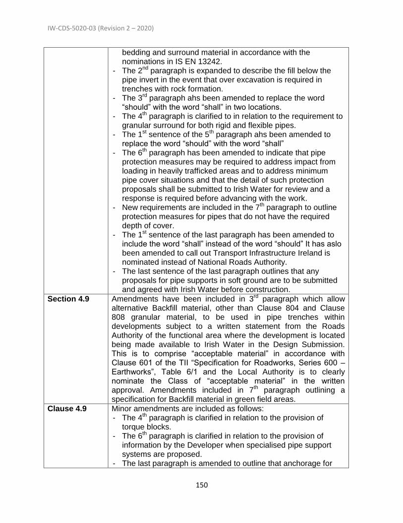
IW-CDS-5020-03 (Revision 2 – 2020)
150
bedding and surround material in accordance with the nominations in IS EN 13242.
- The 2nd paragraph is expanded to describe the fill below the pipe invert in the event that over excavation is required in trenches with rock formation.
- The 3rd paragraph ahs been amended to replace the word “should” with the word “shall” in two locations.
- The 4th paragraph is clarified to in relation to the requirement to granular surround for both rigid and flexible pipes.
- The 1st sentence of the 5th paragraph ahs been amended to replace the word “should” with the word “shall”
- The 6th paragraph has been amended to indicate that pipe protection measures may be required to address impact from loading in heavily trafficked areas and to address minimum pipe cover situations and that the detail of such protection proposals shall be submitted to Irish Water for review and a response is required before advancing with the work.
- New requirements are included in the 7th paragraph to outline protection measures for pipes that do not have the required depth of cover.
- The 1st sentence of the last paragraph has been amended to include the word “shall” instead of the word “should” It has aslo been amended to call out Transport Infrastructure Ireland is nominated instead of National Roads Authority.
- The last sentence of the last paragraph outlines that any proposals for pipe supports in soft ground are to be submitted and agreed with Irish Water before construction.
Section 4.9 Amendments have been included in 3rd paragraph which allow alternative Backfill material, other than Clause 804 and Clause 808 granular material, to be used in pipe trenches within developments subject to a written statement from the Roads Authority of the functional area where the development is located being made available to Irish Water in the Design Submission. This is to comprise “acceptable material” in accordance with Clause 601 of the TII “Specification for Roadworks, Series 600 – Earthworks”, Table 6/1 and the Local Authority is to clearly nominate the Class of “acceptable material” in the written approval. Amendments included in 7th paragraph outlining a specification for Backfill material in green field areas.
Clause 4.9 Minor amendments are included as follows: - The 4th paragraph is clarified in relation to the provision of
torque blocks. - The 6th paragraph is clarified in relation to the provision of
information by the Developer when specialised pipe support systems are proposed.
- The last paragraph is amended to outline that anchorage for

IW-CDS-5020-03 (Revision 2 – 2020)
151
fully integrated PE pipe systems may not require anchorage supports. .
Section 4.10 Amended as follows: - Sub-Section 4.10.1 has been amended to outline the several
steps required for the commissioning of Water Mains. It is indicated that a method statement is to be provided by the Developer for the commissioning of the Main. It is also indicated that compliance with Section 1.12 (Hygiene Requirements) is required during commissioning.
- Sub-Section 4.10.2 has been expanded to outline requirements for the removal of swabs during the cleaning of the Water Mains.
- Sub-Section 4.10.3.1 has been amended to indicate that pressure testing is to be carried out in the presence of Irish Water’s field engineer or agent. It has also been amended to indicate that testing against closed valves is not to be carried out.
- Sub- Section 4.10.3.2 (Ductile Iron Pressure Testing) has been amended to outline revised criteria for DI pipe testing including the requirement for allowing the main to settle for 24 hours rather than “over night”. .
- Sub- Section 4.10.3.3 (Polyethylene Pipe Pressure Testing) has been amended to outline revised criteria for PE pipe testing.
- Sub-Section 4.10.4 has been expanded to outline revised requirements for swabbing after testing and it is indicated that this may be required at the discretion of the field engineer.
- Sub-Section 4.10.5 has been amended in relation to disinfection of Water Mains.
- A new Sub-Section 4.10.6 has been included to outline requirements for disposal of water following disinfection.
- A new Sub-Section 4.10.7 has been included to outline requirements for flushing of Water Mains.
Section 4.11 Amended as follows: - The title of the Section has been amended to “Water Quality
Sampling and Testing”. - The 1st paragraph has been amended to indicate the
requirement for water quality testing following disinfection, flushing, refilling of the main after a standing period of 24 hours.
- A new 2nd paragraph has been included to outline the on-site tests that are required and these are set out in a new Table.
- The 3rd paragraph has been expanded to indicate that chemical as well a microbiological testing is required.
- The 4th paragraph has bene expanded to indicate that the Irish Water field engineer is to be on site when the water quality

IW-CDS-5020-03 (Revision 2 – 2020)
152
sample is being taken. It is also amended to require provision of evidence of the accreditation and range of accredited testing of the sampling/testing laboratory.
- A new 5th paragraph has bene included to outline the sampling locations for the water quality sampling.
- The 6th and 7th paragraph outline the range of off-site parameters to be tested and the acceptable limits for these parameters. .
Section 4.12 Amended as follows: - Sub-Section 4.12.3 has been amended to change
“bacteriological analysis” to “water quality analysis”. - The 2nd paragraph has been amended to indicate that
connection will only be made to the Irish Water Network only when Irish Water is satisfied that all pre-connection requirements as outlined above have been met, that all Final Documents have been submitted and are deemed satisfactory and that a final site walk-off confirms that the infrastructure is to an acceptable standard and that it is fit for purpose.
- The last paragraph has been expanded to indicate that in the event that connection to the Network is not achieved within 14 days, some leeway may be allowed, subject to certain conditions, for the connection to be allowed up to 28 days without the need for additional water quality testing.
Section 4.13 The title of this Section has been amended to “Final Flushing of Water Mains”.
Section 4.14 Section 4.14 has been significantly amended to outline the requirements for the provision of service connection between the installed Water Main and the distribution system with the Premises. It also outlines the pressure tests that are required for the service connection system and outlines the requirement for night flow audits during the Defects Liability Period to confirm the water tightness of the Works.
Part 5 (General amendment)
Part 5 describes requirements for Booster Pump Stations. It has been significantly expanded to include additional electrical, testing, commissioning and associated requirements which were not previously included.
Section 5.1 This Section has been expanded to include aa description of booster pump stations and a diagram of a typical station is provided. It is also indicated that modelling may be required to assess the impact of the booster station on the existing Network.
Section 5.2 A new Section 5.2 has been included to outline what has to be submitted at design stage to Irish Water when booster pump stations are proposed.
Section 5.3 This was previously Section 5.2 and outlines the booster pump station technical requirements. It has been amended as follows: - Sub-Section 5.3.14 has been amended to outline the required
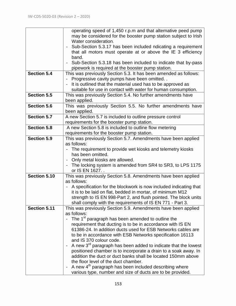
IW-CDS-5020-03 (Revision 2 – 2020)
153
operating speed of 1,450 r.p.m and that alternative peed pump may be considered for the booster pump station subject to Irish Water consideration.
- Sub-Section 5.3.17 has been included ndicating a requirement that all motors must operate at or above the IE 3 efficiency band.
- Sub-Section 5.3.18 has been included to indicate that by-pass pipework is required at the booster pump station.
Section 5.4 This was previously Section 5.3. It has been amended as follows: - Progressive cavity pumps have been omitted. . - It is outlined that the material used has to be approved as
suitable for use in contact with water for human consumption.
Section 5.5 This was previously Section 5.4. No further amendments have been applied.
Section 5.6 This was previously Section 5.5. No further amendments have been applied.
Section 5.7 A new Section 5.7 is included to outline pressure control requirements for the booster pump station.
Section 5.8 A new Section 5.8 is included to outline flow metering requirements for the booster pump station.
Section 5.9 This was previously Section 5.7. Amendments have been applied as follows: - The requirement to provide wet kiosks and telemetry kiosks
has been omitted. - Only metal kiosks are allowed. - The locking system is amended from SR4 to SR3, to LPS 1175
or IS EN 1627. .
Section 5.10 This was previously Section 5.8. Amendments have been applied as follows: - A specification for the blockwork is now included indicating that
it is to be laid on flat, bedded in mortar, of minimum M12 strength to IS EN 998-Part 2, and flush pointed. The block units shall comply with the requirements of IS EN 771 - Part 3.
Section 5.11 This was previously Section 5.9. Amendments have been applied as follows: - The 1st paragraph has been amended to outline the
requirement that ducting is to be in accordance with IS EN 61386-24. In addition ducts used for ESB Networks cables are to be in accordance with ESB Networks specification 16113 and IS 370 colour code.
- A new 3rd paragraph has been added to indicate that the lowest positioned chamber is to incorporate a drain to a soak away. In addition the duct or duct banks shall be located 150mm above the floor level of the duct chamber.
- A new 4th paragraph has been included describing where various type, number and size of ducts are to be provided.
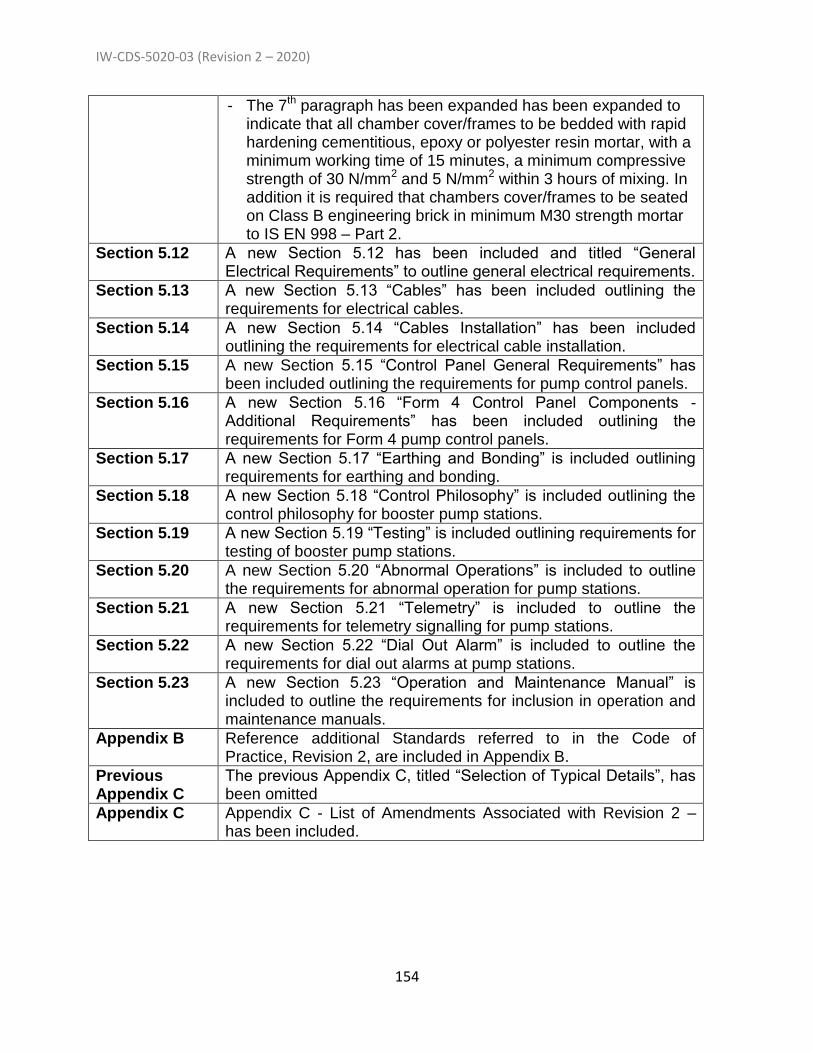
IW-CDS-5020-03 (Revision 2 – 2020)
154
- The 7th paragraph has been expanded has been expanded to indicate that all chamber cover/frames to be bedded with rapid hardening cementitious, epoxy or polyester resin mortar, with a minimum working time of 15 minutes, a minimum compressive strength of 30 N/mm2 and 5 N/mm2 within 3 hours of mixing. In addition it is required that chambers cover/frames to be seated on Class B engineering brick in minimum M30 strength mortar to IS EN 998 – Part 2.
Section 5.12 A new Section 5.12 has been included and titled “General Electrical Requirements” to outline general electrical requirements.
Section 5.13 A new Section 5.13 “Cables” has been included outlining the requirements for electrical cables.
Section 5.14 A new Section 5.14 “Cables Installation” has been included outlining the requirements for electrical cable installation.
Section 5.15 A new Section 5.15 “Control Panel General Requirements” has been included outlining the requirements for pump control panels.
Section 5.16 A new Section 5.16 “Form 4 Control Panel Components - Additional Requirements” has been included outlining the requirements for Form 4 pump control panels.
Section 5.17 A new Section 5.17 “Earthing and Bonding” is included outlining requirements for earthing and bonding.
Section 5.18 A new Section 5.18 “Control Philosophy” is included outlining the control philosophy for booster pump stations.
Section 5.19 A new Section 5.19 “Testing” is included outlining requirements for testing of booster pump stations.
Section 5.20 A new Section 5.20 “Abnormal Operations” is included to outline the requirements for abnormal operation for pump stations.
Section 5.21 A new Section 5.21 “Telemetry” is included to outline the requirements for telemetry signalling for pump stations.
Section 5.22 A new Section 5.22 “Dial Out Alarm” is included to outline the requirements for dial out alarms at pump stations.
Section 5.23 A new Section 5.23 “Operation and Maintenance Manual” is included to outline the requirements for inclusion in operation and maintenance manuals.
Appendix B Reference additional Standards referred to in the Code of Practice, Revision 2, are included in Appendix B.
Previous Appendix C
The previous Appendix C, titled “Selection of Typical Details”, has been omitted
Appendix C Appendix C - List of Amendments Associated with Revision 2 – has been included.

IW-CDS-5020-03 (Revision 2 – 2020)
155