code corporation code reader 2500 fips and code … jackson . added hrng, fixed zeroize to...
TRANSCRIPT

C005582_02 CR2500 FIPS and CR3500 FIPS Security Policy.docx Page 1 of 32 © 2011 The Code Corporation • 14870 S. Pony Express Road, Suite 200, Bluffdale, UT 84065 • (801) 495-2200 • FAX (801) 495-2080
This document can be reproduced and distributed only whole and intact, including this copyright notice.
Code Corporation Code Reader 2500 FIPS and Code Reader 3500 FIPS Security Policy
C005582
03/04/2011
Reviewed By Role Signature Date
Tim Jackson COGE / /
Mark Ashby Engineering / /
Kerri Humpherys Marketing / /
Tony Woodard Application Engineering / /
Mark Gray VPI Engineering / /
Tod Cook Quality Assurance / /

C005582 CR2500 FIPS and CR3500 FIPS Security Policy
C005582_02 CR2500 FIPS and CR3500 FIPS Security Policy.docx Page 2 of 32 © 2011 The Code Corporation • 14870 S. Pony Express Road, Suite 200, Bluffdale, UT 84065 • (801) 495-2200 • FAX (801) 495-0280
This document can be reproduced and distributed only whole and intact, including this copyright notice.
CHANGE RECORD
Revision Date Author Description of Change
00AA Tim Jackson Preliminary Work
00AC 8/5/2010 Tim Jackson Updated inconstancies
00AE 8/6/2010 Tim Jackson 3.2 – update wording in Non-FIPS mode
00AF 8/8/2010 Tim Jackson Added HRNG, fixed zeroize to unauthenticated, minor errors in logical diagrams, standardized firmware placeholder
00AG 8/10/2010 Tim Jackson Updated status output to include all states of FIPS mode
00AH 8/11/2010 Tim Jackson Updated status output to remove amber; added firmware version
00AI 8/11/2010 Tim Jackson Add Reboot Service
00AJ 8/12/2010 Tim Jackson Update inconsistencies of state names
00AK 8/18/2010 Tim Jackson Updated TE pix
00AL 8/24/2010 Tim Jackson Update part numbers, etc.
00AM 8/24/2010 Tim Jackson Updated registered trademarks
00AN 9/3/2010 Tim Jackson Updated typographical errors
00AO 2/24/2011 InfoGard Returned minor changes made on our behalf for approval
01 2/24/11 Tim Jackson Approved minor changes made on our behalf by InfoGard in response to CMVP inquiries
01AA 3/4/2011 InfoGard Returned changes made to Section 9.2
02 3/4/2011 Tim Jackson Approved changes to Section 9.2, updated fax number in footer, footer formatting change, change of Reviewers in table.

C005582 CR2500 FIPS and CR3500 FIPS Security Policy
C005582_02 CR2500 FIPS and CR3500 FIPS Security Policy.docx Page 3 of 32 © 2011 The Code Corporation • 14870 S. Pony Express Road, Suite 200, Bluffdale, UT 84065 • (801) 495-2200 • FAX (801) 495-0280
This document can be reproduced and distributed only whole and intact, including this copyright notice.
Contents 1 Module Overview ............................................................................................................................................ 5 2 Security Level ................................................................................................................................................. 13 3 Modes of Operation ...................................................................................................................................... 14
3.1 FIPS Approved Mode of Operation ............................................................................................................................ 14 3.2 Non-FIPS Mode of Operation .................................................................................................................................... 15 3.3 Approved and Allowed Algorithms ............................................................................................................................ 15
4 Ports and Interfaces ...................................................................................................................................... 17 5 Identification and Authentication Policy ....................................................................................................... 20
5.1 Assumption of Roles .................................................................................................................................................. 20 6 Access Control Policy ..................................................................................................................................... 21
6.1 Roles and Services ..................................................................................................................................................... 21 6.2 Unauthenticated Services .......................................................................................................................................... 21 6.3 Specification of Service Inputs & Outputs.................................................................................................................. 21 6.4 Definition of Critical Security Parameters (CSPs) ....................................................................................................... 23 6.5 Definition of CSPs Modes of Access ........................................................................................................................... 23
7 Operational Environment .............................................................................................................................. 25 8 Security Rules ................................................................................................................................................ 26 9 Physical Security Policy .................................................................................................................................. 27
9.1 Physical Security Mechanisms ................................................................................................................................... 27 9.2 Operator Required Actions ........................................................................................................................................ 27
10 Mitigation of Other Attacks Policy ................................................................................................................ 29 11 Pre-Initialization Mode .................................................................................................................................. 30 12 Delivery Security ............................................................................................................................................ 31 13 References ..................................................................................................................................................... 32 14 Definitions and Acronyms ............................................................................................................................. 32

C005582 CR2500 FIPS and CR3500 FIPS Security Policy
C005582_02 CR2500 FIPS and CR3500 FIPS Security Policy.docx Page 4 of 32 © 2011 The Code Corporation • 14870 S. Pony Express Road, Suite 200, Bluffdale, UT 84065 • (801) 495-2200 • FAX (801) 495-0280
This document can be reproduced and distributed only whole and intact, including this copyright notice.
Tables Table 1 – Module Security Level Specification ....................................................................................................... 13Table 2 – FIPS Approved Algorithms Used in Current Module .............................................................................. 15Table 3 – FIPS Allowed Algorithms Used in Current Module ................................................................................. 16Table 4 – CR2500 FIPS and CR3500 FIPS Bar Code Reader Pins and FIPS 140-2 Ports and Interfaces .................. 17Table 5 – Roles and Required Identification and Authentication .......................................................................... 20Table 6 – Strengths of Authentication Mechanisms .............................................................................................. 20Table 7 – Authenticated Services ........................................................................................................................... 21Table 8 – Unauthenticated Services ....................................................................................................................... 21Table 9 – Specification of Service Inputs & Outputs .............................................................................................. 21Table 10 – Private Keys and CSPs ........................................................................................................................... 23Table 11 – CSP Access Rights within Roles & Services ........................................................................................... 24Table 12 – Inspection/Testing of Physical Security Mechanisms ........................................................................... 27
Figures Figure 1 – Images of the CR2500 FIPS Cryptographic Module ................................................................................. 5Figure 2 – Image of the CR3500 FIPS Cryptographic Module .................................................................................. 6Figure 3 – CR2500 and CR3500 FIPS Bar Code Reader Block Diagram .................................................................... 7Figure 4 – Initialization Logical Block Diagram ......................................................................................................... 8Figure 5 – Authentication Logical Block Diagram .................................................................................................... 9Figure 6 – Generating TEK Logical Block Diagram .................................................................................................. 10Figure 7 – Transmitting Encrypted Data Logical Block Diagram ............................................................................ 11Figure 8 – Zeroization Logical Block Diagram ........................................................................................................ 12Figure 9 – CR3500 FIPS CO Authenticated Status Indication ................................................................................. 15Figure 10 – CR3500 FIPS Un-Authenticated Status Indication ............................................................................... 15Figure 11 – CR3500 FIPS Reader Authenticated Indication ................................................................................... 15Figure 12 – 8-Pin Battery Connector Pin-Out ......................................................................................................... 17Figure 13 – 8-Pin DIN Connector Pin-Out .............................................................................................................. 17Figure 14 – Image of the Cryptographic Module showing the placement of tamper-evident seals ..................... 28

C005582 CR2500 FIPS and CR3500 FIPS Security Policy
C005582_02 CR2500 FIPS and CR3500 FIPS Security Policy.docx Page 5 of 32 © 2011 The Code Corporation • 14870 S. Pony Express Road, Suite 200, Bluffdale, UT 84065 • (801) 495-2200 • FAX (801) 495-0280
This document can be reproduced and distributed only whole and intact, including this copyright notice.
1 Module Overview Code Corporation’s Code Reader 2500 FIPS bar code reader (MFG#: 2512FIPS_01) and Code Reader 3500 FIPS bar code reader (MFG#: 3512FIPS_01) Cryptographic Module (hereafter referred to as the CR2500 FIPS module and the CR3500 FIPS module or collectively as the module) are two configurations of a Multi-Chip Standalone module used as a stand-alone PC accessory designed to connect via Bluetooth® to a CodeXML® FIPS Bluetooth® Modem (BTHDFIPS-M2_01) which in turn connects via USB cable to a computer. The modules allow collecting data contained in a bar code, encrypting it and transmitting it to the computer. The difference between the CR2500 FIPS module and the CR3500 FIPS module are the user interface. The CR2500 FIPS module has two buttons and two LED lights while the CR3500 FIPS module has 21 buttons, one LED light and one LCD screen. The internals of the two modules are otherwise identical and they use the same firmware.
The CR2500 FIPS and CR3500 FIPS serve as data and control interface to the CodeXML® FIPS Bluetooth® Modem. When connected via Bluetooth® to the modem they will pass any commands to the modem, encrypted using an AES-256 dedicated key called a Key Encryption Key (KEK).
The boundary of the modules is the outer case of the physical device.
6 red LED, 2 blue LED & 1 green LED on the camera face of the module are inside the cryptographic boundary excluded from the requirements of FIPS 140-2 because their only purpose is the targeting & illumination for the camera.
Figure 1 – Images of the CR2500 FIPS Cryptographic Module
DIN Connector
Camera Components
Left Red Button
Right Red Button
LED Light LED Light
Speaker

C005582 CR2500 FIPS and CR3500 FIPS Security Policy
C005582_02 CR2500 FIPS and CR3500 FIPS Security Policy.docx Page 6 of 32 © 2011 The Code Corporation • 14870 S. Pony Express Road, Suite 200, Bluffdale, UT 84065 • (801) 495-2200 • FAX (801) 495-0280
This document can be reproduced and distributed only whole and intact, including this copyright notice.
Figure 2 – Image of the CR3500 FIPS Cryptographic Module
The configuration of hardware and firmware for this validation is:
Hardware:
CR2500: 2512FIPS, Version 01
CR3500: 3512FIPS, Version 01
Firmware: 4641
LED Light
Number Pad – 0-9, Shift, Clear
Right SoftKey Navigation Keys – Up, Down, Left Right
Left SoftKey Left Red Button
Right Red Button
LCD Screen
Enter Key
Speaker

C005582 CR2500 FIPS and CR3500 FIPS Security Policy
C005582_02 CR2500 FIPS and CR3500 FIPS Security Policy.docx Page 7 of 32 © 2011 The Code Corporation • 14870 S. Pony Express Road, Suite 200, Bluffdale, UT 84065 • (801) 495-2200 • FAX (801) 495-0280
This document can be reproduced and distributed only whole and intact, including this copyright notice.
Figure 3 depicts a block diagram of the CR2500 FIPS and CR3500 FIPS Bar Code Reader hardware components, with the cryptographic boundary shown in red. The major blocks of the CR2500 and CR3500 FIPS Bar Code Reader hardware are: • Memory: RAM and EEPROM • CPU: AMD Alchemy Au1100-400MBD • Camera (Control Input, Data Input) • Two LED Status Lights – CR2500 (Status
Output • One LED Status Light – CR3500 (Status
Output) • One LCD Status Screen – CR3500 (Status
Output) • Speaker (Status Output) • Vibration Motor (Status Output)
• 2 Buttons – CR2500 (Data Input, Control Input)
• 21 Buttons – CR3500 (Data Input, Control Input)
• Bluetooth® Interface (Data Output) • DIN Interface (Power Interface – Cabled) • Power Interface (Power Interface – Battery) • External Camera Trigger (Control Input –
Battery Pin 7) • Clock
Memory
System Bus
DIN Interface
Data Data Power
LED Light- 2 on CR2500- 1 on CR3500
Bluetooth®
Interface
Encrypted Data, EncryptedPasswords, Encrypted Keys
: Cryptographic Boundary
Status
Buttons - 2 on CR2500- 21 on CR3500
Camera
Data, Control
Control
PowerInterface
Power
Power
Plain Text Data,
Passwords, Keys
Speaker
Status
VibrationMotor
Status
Power
LCDScreen CR3500 only
Status
CPUAMD Alchemy
Au1100-400MBD
Encrypted Data,
Encrypted Passw
ords, Encrypted Keys
Clock
Data
Status
Status
Status
Status
Camera Trigger
Control
Control
Control
Figure 3 – CR2500 and CR3500 FIPS Bar Code Reader Block Diagram

C005582 CR2500 FIPS and CR3500 FIPS Security Policy
C005582_02 CR2500 FIPS and CR3500 FIPS Security Policy.docx Page 8 of 32 © 2011 The Code Corporation • 14870 S. Pony Express Road, Suite 200, Bluffdale, UT 84065 • (801) 495-2200 • FAX (801) 495-0280
This document can be reproduced and distributed only whole and intact, including this copyright notice.
Figure 4 depicts the logical block diagram for Initializing the CR2500 and CR3500 FIPS Bar Code Reader. This process replaces the default Cryptographic Officer Password, Reader (User) Password, and Key Encryption Key with new values chosen by the Cryptographic Officer. This command is only available to the Cryptographic Officer. The readers are the interface to the modem, so the Initialization data is output to the modem encrypted using the old KEK.
Memory
System Bus
Write Plain Text new COPw,RPw & KEK; Read old KEK
Status
LCDScreen (CR3500 only)
Status
Camera
Plain Text new COPw, RPw& KEK; Control
Speaker
Status
VibrationMotor
Status
Plain Text new
CO
Pw, R
Pw &
KEK; Control
Bluetooth®
Interface
KEK Encrypted new COPw,RPw & KEK; Control
Encrypt new COPw, RPw& KEK with old KEK
KEK – Key Encryption KeyCOPw – Cryptographic Officer PasswordRPw – Reader Password
KEK Encrypted new
CO
Pw, R
Pw
& KEK; Control
To Modem
LED Light- 2 on CR2500- 1 on CR3500
CPUAMD Alchemy
Au1100-400MBD
Figure 4 – Initialization Logical Block Diagram

C005582 CR2500 FIPS and CR3500 FIPS Security Policy
C005582_02 CR2500 FIPS and CR3500 FIPS Security Policy.docx Page 9 of 32 © 2011 The Code Corporation • 14870 S. Pony Express Road, Suite 200, Bluffdale, UT 84065 • (801) 495-2200 • FAX (801) 495-0280
This document can be reproduced and distributed only whole and intact, including this copyright notice.
Figure 5 depicts the logical block diagram for Authenticating to the CR2500 and CR3500 FIPS Bar Code Reader. The Authentication process compares a supplied password with a password stored in memory and allows or disallows firmware paths based on the results. The readers are the interface to the modem, so the Authentication data is output to the modem encrypted using the KEK.
Memory
System Bus
Read COPwor RPw & KEK
LCDScreen (CR3500 only)
Status
Camera
Plain Text COPwor RPw, Control
Speaker
Status
VibrationMotor
Plain Text CO
Pw
or RPw
, Control
Compare Passwords,Encrypt Password with KEK
Bluetooth®
Interface
Control; KEK Encrypted Password Status Status
Control; KEK Encrypted
Password To
Modem
LED Light- 2 on CR2500- 1 on CR3500
KEK – Key Encryption KeyCOPw – Cryptographic Officer PasswordRPw – Reader Password
CPUAMD Alchemy
Au1100-400MBD
Figure 5 – Authentication Logical Block Diagram

C005582 CR2500 FIPS and CR3500 FIPS Security Policy
C005582_02 CR2500 FIPS and CR3500 FIPS Security Policy.docx Page 10 of 32 © 2011 The Code Corporation • 14870 S. Pony Express Road, Suite 200, Bluffdale, UT 84065 • (801) 495-2200 • FAX (801) 495-0280
This document can be reproduced and distributed only whole and intact, including this copyright notice.
Figure 6 depicts the logical block diagram for Generating Traffic Encryption Keys (TEK) on the CR2500 and CR3500 FIPS Bar Code Reader. A new TEK is generated for each session initiated between a CR2500 or CR3500 and the CodeXML® FIPS Bluetooth® Modem, seeded by data from the clock. This frequent changing of the TEK provides an added level of security to the Bluetooth® connection. The readers are the interface to the modem, so the new TEK data is output to the modem encrypted using the KEK.
Memory
System Bus
Write TEK;Read KEK
Camera
Control; Data HRNG
Control
Generate TrafficEncryption Key
Bluetooth®
Interface
Encrypted new TEK; Control
Encrypted new
TE
K; C
ontrol To M
odem
KEK – Key Encryption KeyTEK – Traffic Encryption Key
Clock
Data HRNG
CPUAMD Alchemy
Au1100-400MBD
Figure 6 – Generating TEK Logical Block Diagram
C005582 CR2500 FIPS and CR3500 FIPS Security Policy
C005582_02 CR2500 FIPS and CR3500 FIPS Security Policy.docx Page 11 of 32 © 2011 The Code Corporation • 14870 S. Pony Express Road, Suite 200, Bluffdale, UT 84065 • (801) 495-2200 • FAX (801) 495-0280
This document can be reproduced and distributed only whole and intact, including this copyright notice.
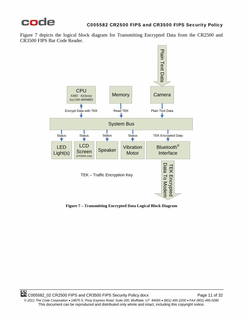
Figure 7 depicts the logical block diagram for Transmitting Encrypted Data from the CR2500 and CR3500 FIPS Bar Code Reader.
Memory
System Bus
Read TEK
LEDLight(s)
Status Status
Camera
Plain Text Data
Speaker
Status
VibrationMotor
Plain Text D
ata
Encrypt Data with TEK
LCDScreen (CR3500 only)
Bluetooth®
Interface
TEK Encrypted Data
TEK
Encrypted
Data To M
odem
TEK – Traffic Encryption Key
Status
CPUAMD Alchemy
Au1100-400MBD
Figure 7 – Transmitting Encrypted Data Logical Block Diagram

C005582 CR2500 FIPS and CR3500 FIPS Security Policy
C005582_02 CR2500 FIPS and CR3500 FIPS Security Policy.docx Page 12 of 32 © 2011 The Code Corporation • 14870 S. Pony Express Road, Suite 200, Bluffdale, UT 84065 • (801) 495-2200 • FAX (801) 495-0280
This document can be reproduced and distributed only whole and intact, including this copyright notice.
Figure 8 depicts the logical block diagram for Zeroizing the CR2500 and CR3500 FIPS Bar Code Reader. All four CSP are reset back to defaults in this procedure – Cryptographic Officer Password, Reader (User) Password, Key Encryption Key and Traffic Encryption Key.
Memory
System Bus
Reset Plain Text Passwords &Encryption Keys
Camera
ControlC
ontrol
Bluetooth®
Interface
Control
Control To M
odem
Figure 8 – Zeroization Logical Block Diagram
Module services are described in Section 6 below.

C005582 CR2500 FIPS and CR3500 FIPS Security Policy
C005582_02 CR2500 FIPS and CR3500 FIPS Security Policy.docx Page 13 of 32 © 2011 The Code Corporation • 14870 S. Pony Express Road, Suite 200, Bluffdale, UT 84065 • (801) 495-2200 • FAX (801) 495-0280
This document can be reproduced and distributed only whole and intact, including this copyright notice.
2 Security Level The cryptographic module meets the overall requirements applicable to Level 2 security of FIPS 140-2.
Table 1 – Module Security Level Specification
Security Requirements Section Level Cryptographic Module Specification 3 Module Ports and Interfaces 2 Roles, Services and Authentication 2 Finite State Model 2 Physical Security 2 Operational Environment N/A Cryptographic Key Management 2 EMI/EMC 2 Self-Tests 2 Design Assurance 3 Mitigation of Other Attacks N/A

C005582 CR2500 FIPS and CR3500 FIPS Security Policy
C005582_02 CR2500 FIPS and CR3500 FIPS Security Policy.docx Page 14 of 32 © 2011 The Code Corporation • 14870 S. Pony Express Road, Suite 200, Bluffdale, UT 84065 • (801) 495-2200 • FAX (801) 495-0280
This document can be reproduced and distributed only whole and intact, including this copyright notice.
3 Modes of Operation 3.1 FIPS Approved Mode of Operation The module provides a FIPS Approved mode of operation, comprising all services described in Section 6 below and a non-FIPS mode where the modules respond in the same manner as non-FIPS Code devices.
The module will enter FIPS Approved mode following successful power up self tests and initialization, provided the device has been properly initialized via the Initialization service.
While in FIPS Approved mode there are three stages indicated by the Status Output of the modules – CO Authenticated, Un-Authenticated, and Reader (User) Authenticated.
The CR2500 module indicates the three stages in the following manner:
• CO Authenticated – the module will indicate this mode of operation by blinking the blue Left LED light in a 1 second on, 1 second off pattern.
• Un-Authenticated – the module will indicate this mode of operation by blinking the blue Left LED light in a 2 seconds on, 1 second off pattern.
• Reader (User) Authenticated – the module will indicate this mode of operation by blinking the blue Left LED light in a Morse Code ‘F’ pattern. The Morse Code ‘F’ is comprised of two short
dots, a long dash and a short dot ( F ) followed by a 3.5 second delay.
The CR3500 module indicates the three stages in the following manner:
• CO Authenticated – the module will automatically indicate this mode of operation by displaying Packet Mode Icon of the letter ‘FA’ on the top line of the reader display as shown in Figure 9 below.
• Un-Authenticated – the module will automatically indicate this mode of operation by displaying Packet Mode Icon of the letter ‘FR’ on the top line of the reader display as shown in Figure 10 below.
• Reader (User) Authenticated – the module will automatically indicate this mode of operation by displaying Packet Mode Icon of the letter ‘F’ on the top line of the reader display as shown in Figure 11 below.

C005582 CR2500 FIPS and CR3500 FIPS Security Policy
C005582_02 CR2500 FIPS and CR3500 FIPS Security Policy.docx Page 15 of 32 © 2011 The Code Corporation • 14870 S. Pony Express Road, Suite 200, Bluffdale, UT 84065 • (801) 495-2200 • FAX (801) 495-0280
This document can be reproduced and distributed only whole and intact, including this copyright notice.
Figure 9 – CR3500 FIPS CO Authenticated Status Indication
Figure 10 – CR3500 FIPS Un-Authenticated Status Indication
Figure 11 – CR3500 FIPS Reader (User) Authenticated Indication
3.2 Non-FIPS Mode of Operation If the Power-on Initialization determines that the module has not been Initialized, the module does not provide access to any Cryptographic functions. In this state, the module will function as a non-FIPS Code reader would function – the modules will pass plain text data. This is the non-FIPS mode of operation for the module.
3.3 Approved and Allowed Algorithms The cryptographic module supports the following FIPS Approved algorithms.
Table 2 – FIPS Approved Algorithms Used in Current Module
FIPS Approved Algorithm CAVP Cert. # AES: ECB; 128 and 256 bit Cert. # 1457 AES: CTR; 256 bit; External Counter Cert. # 1457 Block Cipher DRBG: AES; 256 bit Cert. #55
The cryptographic module supports the following non-FIPS Approved algorithms which are allowed for use in FIPS mode.

C005582 CR2500 FIPS and CR3500 FIPS Security Policy
C005582_02 CR2500 FIPS and CR3500 FIPS Security Policy.docx Page 16 of 32 © 2011 The Code Corporation • 14870 S. Pony Express Road, Suite 200, Bluffdale, UT 84065 • (801) 495-2200 • FAX (801) 495-0280
This document can be reproduced and distributed only whole and intact, including this copyright notice.
Table 3 – FIPS Allowed Algorithms Used in Current Module
FIPS Allowed Algorithm Hardware RNG: used to seed FIPS Approved DRBG

C005582 CR2500 FIPS and CR3500 FIPS Security Policy
C005582_02 CR2500 FIPS and CR3500 FIPS Security Policy.docx Page 17 of 32 © 2011 The Code Corporation • 14870 S. Pony Express Road, Suite 200, Bluffdale, UT 84065 • (801) 495-2200 • FAX (801) 495-0280
This document can be reproduced and distributed only whole and intact, including this copyright notice.
4 Ports and Interfaces The CR2500 FIPS and CR3500 FIPS bar code reader is a multi-chip standalone cryptographic module with ports and interfaces as shown below.
Figure 12 – 8-Pin Battery Connector Pin-Out
Figure 13 – 8-Pin DIN Connector Pin-Out
Table 4 – CR2500 FIPS and CR3500 FIPS Bar Code Reader Pins and FIPS 140-2 Ports and Interfaces
Pin Module FIPS 140-2 Designation
Name and Description
Battery Bay (BB) Pin 1
CR2500 & CR3500
Power Port Input voltage (3.5V-5.5V)
BB Pin 2 CR2500 & CR3500
Power Port Regulated main system voltage (3.3V)
BB Pin 3 CR2500 & CR3500
Power Port Signal to indicate battery charge level
BB Pin 4 CR2500 & CR3500
Power Port Signal to indicate battery charge level
BB Pin 5 CR2500 & CR3500
Power Port Power to battery from DIN connector. Voltage (0V-4.2V)
BB Pin 6 CR2500 & CR3500
Power Port Signal to switch between charging the battery at a low rate (100mA) and a high rate (500mA)
BB Pin 7 CR2500 & CR3500
Control Input Signal for an external camera trigger
BB Pin 8 CR2500 & CR3500
Power Port Ground
Battery Bay Pin 1
Battery Bay Pin 8

C005582 CR2500 FIPS and CR3500 FIPS Security Policy
C005582_02 CR2500 FIPS and CR3500 FIPS Security Policy.docx Page 18 of 32 © 2011 The Code Corporation • 14870 S. Pony Express Road, Suite 200, Bluffdale, UT 84065 • (801) 495-2200 • FAX (801) 495-0280
This document can be reproduced and distributed only whole and intact, including this copyright notice.
8-Pin DIN Connector Pin 1 (DIN1)
CR2500 & CR3500
Power Port VIN - Input Voltage to the voltage regulators/batter charging IC
DIN2 CR2500 & CR3500
N/A Data transfer via DIN cable (in or out of module) is disabled via firmware while in FIPS Mode.
DIN3 CR2500 & CR3500
N/A Data transfer via DIN cable (in or out of module) is disabled via firmware while in FIPS Mode.
DIN4 CR2500 & CR3500
N/A Data transfer via DIN cable (in or out of module) is disabled via firmware while in FIPS Mode.
DIN5 CR2500 & CR3500
N/A Data transfer via DIN cable (in or out of module) is disabled via firmware while in FIPS Mode.
DIN6 CR2500 & CR3500
N/A Data transfer via DIN cable (in or out of module) is disabled via firmware while in FIPS Mode.
DIN7 CR2500 & CR3500
N/A External trigger via DIN cable is disabled via firmware while in FIPS Mode.
DIN8 CR2500 & CR3500
Power Port Ground
LCD Screen CR3500 Status Output Displays FIPS status LED Light CR2500 &
CR3500 Status Output Displays FIPS status – Transmit Data/Error
Speaker CR2500 & CR3500
Status Output Conveys FIPS status – Transmit Data/Error
Camera CR2500 & CR3500
Control Input / Data Input
Reads bar codes containing Commands and Data
Bluetooth® Interface
CR2500 & CR3500
Data Output Transmits Data to Modem, receives responses from Modem
L SoftKey CR3500 Data Input Programmable Key for Data Input R SoftKey CR3500 Data Input Programmable Key for Data Input L Red Button CR2500 &
CR3500 Control Input Camera Trigger
R Red Button CR2500 & CR3500
Control Input Camera Trigger
Navigation Ring (Up)
CR3500 Control Input Navigation Key for Data Input – move cursor up
Navigation Ring (Down)
CR3500 Control Input Navigation Key for Data Input – move cursor down
Navigation Ring (Left)
CR3500 Control Input Navigation Key for Data Input – move cursor left

C005582 CR2500 FIPS and CR3500 FIPS Security Policy
C005582_02 CR2500 FIPS and CR3500 FIPS Security Policy.docx Page 19 of 32 © 2011 The Code Corporation • 14870 S. Pony Express Road, Suite 200, Bluffdale, UT 84065 • (801) 495-2200 • FAX (801) 495-0280
This document can be reproduced and distributed only whole and intact, including this copyright notice.
Navigation Ring (Right)
CR3500 Control Input Navigation Key for Data Input – move cursor right
Enter (Blue) Button
CR3500 Control Input Accepts Data Text Stream
1 Key CR3500 Data Input Enters ‘1’ or ‘Space’ into the Data Text Stream 2 Key CR3500 Data Input Enters ‘2’, ‘A’, ‘B’ or ‘C’ into the Data Text Stream 3 Key CR3500 Data Input Enters ‘3’, ‘D’, ‘E’ or ‘F’ into the Data Text Stream 4 Key CR3500 Data Input Enters ‘4’, ‘G’, ‘H’ or ‘I’ into the Data Text Stream 5 Key CR3500 Data Input Enters ‘5’, ‘J’, ‘K’ or ‘L’ into the Data Text Stream 6 Key CR3500 Data Input Enters ‘6’, ‘M’, ‘N’ or ‘O’ into the Data Text Stream 7 Key CR3500 Data Input Enters ‘7’, ‘P’, ‘Q’, ‘R’ or ‘S’ into the Data Text
Stream 8 Key CR3500 Data Input Enters ‘8’, ‘T’, ‘U’ or ‘V’ into the Data Text Stream 9 Key CR3500 Data Input Enters ‘9’, ‘W’, ‘X’, ‘Y’ or ‘Z’ into the Data Text
Stream 0 Key CR3500 Data Input Enters ‘0’ into the Data Text Stream Shift Key CR3500 Data Input Toggles between numeric characters, upper case text,
lower case text, and symbol character input Clear Key CR3500 Data Input Clears Data Text Stream

C005582 CR2500 FIPS and CR3500 FIPS Security Policy
C005582_02 CR2500 FIPS and CR3500 FIPS Security Policy.docx Page 20 of 32 © 2011 The Code Corporation • 14870 S. Pony Express Road, Suite 200, Bluffdale, UT 84065 • (801) 495-2200 • FAX (801) 495-0280
This document can be reproduced and distributed only whole and intact, including this copyright notice.
5 Identification and Authentication Policy 5.1 Assumption of Roles The module supports two distinct operator roles, Reader (User) and Cryptographic Officer (CO). The cryptographic module enforces the separation of roles using re-authentication when changing roles. The Reader role is not allowed to change passwords on the device and the CO role is not allowed to send encrypted data.
Authentication is based on fixed-length, eight-character passwords using any character value in the range 0x20 - 0xFF.
The module provides neither a maintenance role or bypass capability. Table 5 – Roles and Required Identification and Authentication
Role Description Authentication Type Authentication Data
CRYPTOGRAPHIC OFFICER
This role has access to initialize and zeroize the module. The CO is not allowed to transmit data.
Role-based operator authentication
Password is fixed at eight characters from the set 0x20 through 0xFF. Password must be scanned from a Data Matrix (ECC) barcode via the camera. No manual entry of Password is allowed.
READER (USER) This role has access to data transmission and zeroize services. The Reader is not allowed to initialize.
Role-based operator authentication
Password is fixed at eight characters from the set 0x20 through 0xFF. Password must be scanned from a Data Matrix (ECC) barcode via the camera. No manual entry of Password is allowed.
Table 6 – Strengths of Authentication Mechanisms
Authentication Mechanism Strength of Mechanism
Passwords (Fixed-length, eight characters; 0x20-0xFF Extended ASCII character set)
The probability that a random attempt will succeed or a false acceptance will occur is a minimum of 1/ 23*225 or 1/2675 or 1/ 1.5676426594103495798233121284485x10203 which is less than 1/1,000,000.
The probability of successfully authenticating to the module within one minute through random attempts is a minimum of 1/2(3*225)-12.55 or 1/2662.45 or 1/ 2.61409055292975750304018840341x10199 which is less than 1/100,000.
The calculations are based on eight character (23) passwords built from a 225 character set. Code readers can read 6000 (or ~ 212.55) bar codes per minute under ideal conditions.

C005582 CR2500 FIPS and CR3500 FIPS Security Policy
C005582_02 CR2500 FIPS and CR3500 FIPS Security Policy.docx Page 21 of 32 © 2011 The Code Corporation • 14870 S. Pony Express Road, Suite 200, Bluffdale, UT 84065 • (801) 495-2200 • FAX (801) 495-0280
This document can be reproduced and distributed only whole and intact, including this copyright notice.
6 Access Control Policy 6.1 Roles and Services
Table 7 – Authenticated Services
Service CO Reader Description
Authenticate X X Ensures the operator assuming role is authorized and limits the services available to a role.
Initialize X Sets Cryptographic Officer Password, Reader Password, and Key Encryption Key.
Generate TEK X Generate a Traffic Encryption Key to encrypt data sent from reader module to modem module.
Transmit Encrypted Data X Transfer data from the Reader to the Modem using the
Traffic Encryption Key. Reboot X X Deletes CSPs and reboots module
6.2 Unauthenticated Services The cryptographic module supports the following unauthenticated services:
Table 8 – Unauthenticated Services
Service Description Self Test Re-runs Power-On Self Test Zeroize Clears Encryption Keys and Passwords. Requires the Initialize Command to be
run to return to FIPS functionality.
6.3 Specification of Service Inputs & Outputs Table 9 – Specification of Service Inputs & Outputs
Service Control Input Data Input Data Output Status Output
Self-Test N/A N/A N/A On FAIL - CR2500 & CR3500: AES/DRBG - LED Light flashes red .5 sec on, .5 sec off; Speaker/Vibration Motor CRC – Three Beeps On Success – CR2500: LED Light flashes blue 2 second on, 1 second off.

C005582 CR2500 FIPS and CR3500 FIPS Security Policy
C005582_02 CR2500 FIPS and CR3500 FIPS Security Policy.docx Page 22 of 32 © 2011 The Code Corporation • 14870 S. Pony Express Road, Suite 200, Bluffdale, UT 84065 • (801) 495-2200 • FAX (801) 495-0280
This document can be reproduced and distributed only whole and intact, including this copyright notice.
On Success – CR3500: LED Screen displays ‘FR’ on the top right of the information bar.
Initialize Left or Right Red Button press to activate camera
Initialize command, two eight character passwords and a 256 bit Key Encryption Key decoded from a Data Matrix bar code
Plain text control and KEK Encrypted Passwords and KEK encrypted new KEK via Bluetooth® Wireless to Modem
CR2500: LED Light flashes blue 1 second on, 1 second off.
CR3500: LCD Screen displays ‘FA’ on the top right of the information bar.
Generate TEK
Authenticate Reader Role; paired with a Modem module
Authenticate command and eight character Reader password decoded from a Data Matrix bar code
Plain text control and KEK Encrypted TEK via Bluetooth® Wireless to Modem
CR2500: LED Light flashes Morse Code ‘F’ ( F ).
CR3500: LCD Screen displays ‘F’ on the top right of the information bar.
Authenticate Left or Right Red Button press to activate camera
Authenticate command and one eight character passwords decoded from a Data Matrix bar code
Plain text control and KEK Encrypted CO or Reader password via Bluetooth® Wireless to Modem
CR2500: Authenticate CO - LED Light flashes blue 1 second on, 1 second off. Authenticate READER - LED Light flashes Morse Code ‘F’ ( F ). CR3500: Authenticate CO - LCD Screen displays ‘FA’ on the top right of the information bar. Authenticate READER - LCD Screen displays ‘F’ on the top right of the information bar.
Zeroize Left or Right Red Button press to activate camera
Zeroize command decoded from a Data Matrix bar code
Plain text control via Bluetooth® Wireless to Modem
CR2500: LED Light no longer flashes Morse Code ‘F’ ( F ). CR3500: LED Screen no longer displays ‘F’.
C005582 CR2500 FIPS and CR3500 FIPS Security Policy
C005582_02 CR2500 FIPS and CR3500 FIPS Security Policy.docx Page 23 of 32 © 2011 The Code Corporation • 14870 S. Pony Express Road, Suite 200, Bluffdale, UT 84065 • (801) 495-2200 • FAX (801) 495-0280
This document can be reproduced and distributed only whole and intact, including this copyright notice.
Transmit Encrypted Data
Left or Right Red Button press to activate camera
Clear-text data decoded from a bar code or OCR
TEK Encrypted Data via Bluetooth® Wireless to Modem
CR2500: LED Light flashes Morse Code ‘F’ ( F ).
CR3500: LCD Screen displays ‘F’ on the top right of the information bar.
Reboot Commands to change the communication mode of the reader
Clear-text data from camera
Plain text control via Bluetooth® Wireless to Modem
CR2500: LED Light no longer flashes Morse Code ‘F’ ( F ). CR3500: LCD Screen no longer displays ‘F’.
6.4 Definition of Critical Security Parameters (CSPs) The module contains the following CSPs:
Table 10 – Private Keys and CSPs
Key Name Type Description Key Encryption Key
AES-256: ECB Key used to encrypt session-based Traffic Encryption Key as well as other CSPs sent to modem. Set in Initialization procedure.
DRBG Seed Hardware RNG output Hardware RNG seed; Generated and used, never stored.
Traffic Encryption Key
AES-256: CTR Key used to encrypt data sent from Reader to Modem. This key is re-generated for each session to provide a higher level of confidentiality.
Reader Password Eight characters; 0x20-0xFF character set
Password used to authenticate the Reader (User) role
Cryptographic Officer Password
Eight characters; 0x20-0xFF character set
Password used to authenticate the Cryptographic Officer role
6.5 Definition of CSPs Modes of Access Table 13 defines the relationship between access to CSPs and the different module services. The modes of access shown in the table are defined as:
• G = Generate
•
: The module generates the CSP.
R = Read
•
: The module reads the CSP. The read access is typically performed before the module uses the CSP.
W = Write: The module writes the CSP. The write access is typically performed after a CSP is imported into the module, or the module generates a CSP, or the module overwrites an existing CSP.

C005582 CR2500 FIPS and CR3500 FIPS Security Policy
C005582_02 CR2500 FIPS and CR3500 FIPS Security Policy.docx Page 24 of 32 © 2011 The Code Corporation • 14870 S. Pony Express Road, Suite 200, Bluffdale, UT 84065 • (801) 495-2200 • FAX (801) 495-0280
This document can be reproduced and distributed only whole and intact, including this copyright notice.
• Z = ZeroizeTable 11 – CSP Access Rights within Roles & Services
: The module zeroizes the CSP.
Role Authorized Service Mode Cryptographic Key or CSP CO Authenticate R
R Cryptographic Officer Password Key Encryption Key
Initialize W W W R
New Key Encryption Key Reader Password Cryptographic Officer Password Existing Key Encryption Key
Reader (User) Authenticate R R
Reader Password Key Encryption Key
Transmit Encrypted Data R Traffic Encryption Key Generate TEK G
W Traffic Encryption Key Traffic Encryption Key
Un-Authenticated or Any Role
Zeroize Z Z Z Z
Key Encryption Key Traffic Encryption Key Reader Password CO Password
Self-Test N/A N/A Reboot Z Traffic Encryption Key

C005582 CR2500 FIPS and CR3500 FIPS Security Policy
C005582_02 CR2500 FIPS and CR3500 FIPS Security Policy.docx Page 25 of 32 © 2011 The Code Corporation • 14870 S. Pony Express Road, Suite 200, Bluffdale, UT 84065 • (801) 495-2200 • FAX (801) 495-0280
This document can be reproduced and distributed only whole and intact, including this copyright notice.
7 Operational Environment The FIPS 140-2 Area 6 Operational Environment requirements are not applicable because the CR2500 FIPS and CR3500 FIPS bar code readers do not contain a modifiable operational environment.

C005582 CR2500 FIPS and CR3500 FIPS Security Policy
C005582_02 CR2500 FIPS and CR3500 FIPS Security Policy.docx Page 26 of 32 © 2011 The Code Corporation • 14870 S. Pony Express Road, Suite 200, Bluffdale, UT 84065 • (801) 495-2200 • FAX (801) 495-0280
This document can be reproduced and distributed only whole and intact, including this copyright notice.
8 Security Rules The CR2500 FIPS and CR3500 FIPS bar code reader design corresponds to the CR2500 FIPS and CR3500 FIPS bar code reader security rules. This section documents the security rules enforced by the cryptographic module to implement the security requirements of this FIPS 140-2 Level 2 module.
1. The cryptographic module shall provide role-based authentication. 2. The cryptographic module shall provide two distinct operator roles. These are the Reader (User)
role, and the Cryptographic Officer role. 3. The cryptographic module shall clear previous authentications on power cycle 4. The cryptographic module shall clear Traffic Encryption Keys on power cycle by overwriting with
zeroes.
5. When the module has not been placed in a valid role, the operator shall not have access to any cryptographic services.
6. The cryptographic module shall perform the following tests 6.1. Power up Self-Tests
6.1.1. Critical function tests: Board initialization tests 6.1.2. Cryptographic algorithm tests
6.1.2.1. SP800-90 DRBG Known Answer Test 6.1.2.2. AES Encrypt and Decrypt Known Answer Test
6.1.3. Firmware Integrity Test – CRC16 check of firmware on load (power on) 6.2. Conditional Self-Test - Continuous Random Number Generator (RNG) test – performed on
DRBG and Hardware RNG 7. The operator shall be capable of commanding the module to perform the power-up self-test by
cycling the power of the module by removing and replacing the battery. 8. Power-up self tests do not require any operator action. 9. Data output shall be inhibited during key generation, self-tests, zeroization, and error states. 10. Status information does not contain CSPs or sensitive data that if misused could lead to a
compromise of the module. 11. There are no restrictions on which keys or CSPs are zeroized by the zeroization service. 12. The module does not support concurrent operators. 13. The module does not support a maintenance interface or role. 14. The module does not support manual key entry. 15. The module only accepts commands, passwords and keys from Data Matrix bar codes via the
camera interface. Data Matrix bar codes contain Error Correction Codes (ECC) to ensure integrity of data. Manual entry of CSPs via the keyboard is not allowed.
16. The module does not have any external input/output devices used for entry/output of data. 17. The module does not output intermediate key values. 18. The module does not support the update of the firmware.

C005582 CR2500 FIPS and CR3500 FIPS Security Policy
C005582_02 CR2500 FIPS and CR3500 FIPS Security Policy.docx Page 27 of 32 © 2011 The Code Corporation • 14870 S. Pony Express Road, Suite 200, Bluffdale, UT 84065 • (801) 495-2200 • FAX (801) 495-0280
This document can be reproduced and distributed only whole and intact, including this copyright notice.
9 Physical Security Policy 9.1 Physical Security Mechanisms The multi-chip standalone CR2500 FIPS and CR3500 FIPS cryptographic modules are comprised of production-grade components and encased in a production-grade opaque enclosure. Four shell screws on each module are covered with blue tamper evident compound. The tamper evident compound is applied to the modules by Code Corporation in manufacturing before distribution to the end user.
9.2 Operator Required Actions Examine the tamper evident seals monthly.
Table 12 – Inspection/Testing of Physical Security Mechanisms
Physical Security Mechanisms
Recommended Frequency of Inspection/Test
Inspection/Test Guidance Details
Tamper Evident Seals
1 month There are four tamper-evident seals on each module. Four (of six) of the screw holes in the bottom of the case will be filled with blue tamper evident compound (see Figure 14, below). The compound dries into a hard, brittle substance. Inspect the screw holes for any signs of scratching or broken compound. If any tampering is suspected, return the module to Code Corporation for testing and replacement of the tamper evident compound. Additionally, inspect the enclosure for visible signs of tampering (e.g., attempts to remove keypads or cracks in the LCD assembly).

C005582 CR2500 FIPS and CR3500 FIPS Security Policy
C005582_02 CR2500 FIPS and CR3500 FIPS Security Policy.docx Page 28 of 32 © 2011 The Code Corporation • 14870 S. Pony Express Road, Suite 200, Bluffdale, UT 84065 • (801) 495-2200 • FAX (801) 495-0280
This document can be reproduced and distributed only whole and intact, including this copyright notice.
Figure 14 – Image showing the placement of tamper-evident seals (same for CR2500 FIPS and CR3500 FIPS)
C005582 CR2500 FIPS and CR3500 FIPS Security Policy
C005582_02 CR2500 FIPS and CR3500 FIPS Security Policy.docx Page 29 of 32 © 2011 The Code Corporation • 14870 S. Pony Express Road, Suite 200, Bluffdale, UT 84065 • (801) 495-2200 • FAX (801) 495-0280
This document can be reproduced and distributed only whole and intact, including this copyright notice.
10 Mitigation of Other Attacks Policy The module has not been designed to mitigate attacks that are outside of the scope of FIPS 140-2.

C005582 CR2500 FIPS and CR3500 FIPS Security Policy
C005582_02 CR2500 FIPS and CR3500 FIPS Security Policy.docx Page 30 of 32 © 2011 The Code Corporation • 14870 S. Pony Express Road, Suite 200, Bluffdale, UT 84065 • (801) 495-2200 • FAX (801) 495-0280
This document can be reproduced and distributed only whole and intact, including this copyright notice.
11 Pre-Initialization Mode The module employs a Pre-Initialization mode that employs default values for the Cryptographic Officer role password, the Reader (User) role password and the Key Encryption Key. The only service that is available in pre-initialization mode is Authentication of the CO role. Once Authenticated the CO is required to Initialize the module before the Reader (User) role can be Authenticated.
The module returns to the Pre-Initialization state after it receives the Zeroization command. The passwords and KEK are returned to default and the TEK is overwritten with zeroes.

C005582 CR2500 FIPS and CR3500 FIPS Security Policy
C005582_02 CR2500 FIPS and CR3500 FIPS Security Policy.docx Page 31 of 32 © 2011 The Code Corporation • 14870 S. Pony Express Road, Suite 200, Bluffdale, UT 84065 • (801) 495-2200 • FAX (801) 495-0280
This document can be reproduced and distributed only whole and intact, including this copyright notice.
12 Delivery Security The modules will be packed by Code Corporation representatives, sealed with packing tape, and then delivered via common carrier using a tracking code to the end user or their delegate. If the package is damaged in shipping, inspect the Tamper Evident seals to determine if the modules have been compromised.

C005582 CR2500 FIPS and CR3500 FIPS Security Policy
C005582_02 CR2500 FIPS and CR3500 FIPS Security Policy.docx Page 32 of 32 © 2011 The Code Corporation • 14870 S. Pony Express Road, Suite 200, Bluffdale, UT 84065 • (801) 495-2200 • FAX (801) 495-0280
This document can be reproduced and distributed only whole and intact, including this copyright notice.
13 References [FIPS 140-2] FIPS Publication 140-2 Security Requirements for Cryptographic Modules [FIPS 197] FIPS Publication 197 ADVANCED ENCRYPTION STANDARD (AES) [DRBG] NIST SP 800-90 Recommendation for Random Number Generation Using Deterministic Random Bit Generators (Revised)
14 Definitions and Acronyms KEK – Key Encryption Key; Encrypts passwords and keys exchanged between Reader and Modem
TEK – Traffic Encryption Key; Encrypts data exchanged between Reader and Modem