coatings capable of performinga. s. khanna iit bombay, india. inorganic-organic hybrid based smart...
TRANSCRIPT

Department of Metallurgical Engineering & Materials Science
A. S. Khanna
IIT Bombay, India

Inorganic-organic hybrid based Smart Coatings
A.S.Khanna
Department of Metallurgical Engineering & Materials Science
IIT Bombay

Definition Smart Coatings
Coatings capable of performing some pre-determined function

Some Example of Smart Coatings
Self Healing Self Cleaning
ConductiveCorrosion sensing
Light sensing Photo catalytic

Self Cleaning
•The action of water drop will depend upon whether the surface is hydrophobic or hydrophilic
Coatings on which dust
can be removed
using some stimuli –may be
water drop

The ability of surfaces to makewater bead off completely andthereby wash off contaminationvery effectively is called as “Lotusleaf effect”
Macro – nano surfacemorphology & very low surfaceenergy due to Cuticular Waxproduces lotus effect on thesurface
Roughness
Low energy –wax crystals

Lower Surface Energy
Surface Roughness
Super Hydrphobicicity
Lower Surface Energy: –CF3 < –CF2 < –CH3 < –CH2
Surface Roughness: Micro Nano Texturing (C.A > 130)
C.A < 90 C.A < 120 C.A > 150

How to make a surface Hydrophobic ?
• Grafting with fluro-based polymers which saturate the surface with strong bonding
• Changing the surface roughness
• By physically changing the surface roughness by various etching processes
• By addition of nano particles
• A combination of fluropolymers and nanoparticles
• Non-fluro approach
We followed
three approaches
:

Inorganic-Organic Hybrids• Organic-inorganic hybrids are molecules containing a metal core bonded to
reactive alkoxy groups and/or organic groups
SiOCH3
OCH3
OCH3
Organic component
Inorganic component
Epoxy, Isocynate, Ester,Vinyl, Acrylate, Amino, Polyurethane
Alkoxide of silicon
Organic- Inorganic Hybrid of silicon: Organosilane

Nomenclature of IOH
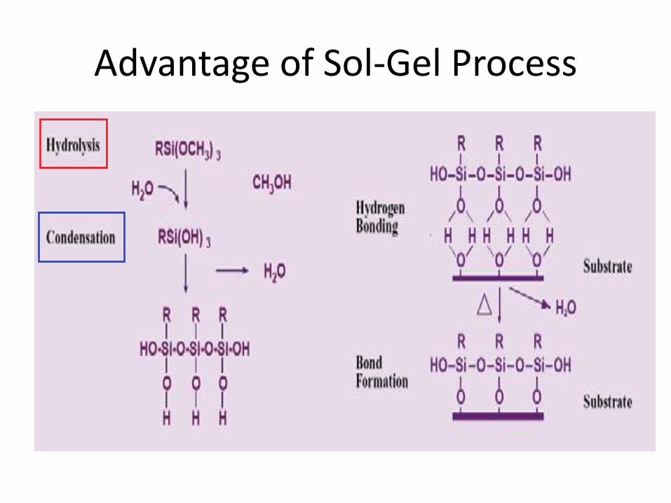
Advantage of Sol-Gel Process

12
Sol-gel Coatings: The Work done at IITB• Inorganic –organic Hybrid Coatings – having properties of bothinorganic materials and organic materials
• Precursors for coating formulation
Methyltrimethoxysilane (MTMS) 3-glycidoxypropyltrimethoxysilane(GPTMS) 3-aminopropyltriethoxysilane (1N) N-(2-aminoethyl)-3-aminopropyltrimethoxysilane (2N) Hexamethoxymethylmelamine (HMMM) Waterborne polyester(WPE) Waterborne alkyd(WKD)
Coating formulations Epoxysilane coatings Polyester incorporated epoxysilane coatings Alkyd incorporated eposysilane coatings
O
O Si
OCH3
OCH3
OCH3
H3CSi
OCH3
OCH3
OCH3
H2NSi
OCH3
OCH3
OCH3
CN
N
N
NNCH2OCH3
N
CH2OCH3CH3OCH2
CH3OCH2
CH2OCH3CH3OCH2
H2N HNSi
OCH3
OCH3
OCH3

Characterization of Neat Sol gel
75°RMS ~ 3nm
Smooth profile

Fluro Approach
3, 3-Trifluropropyltrimethoxy silane
Perflurodecyltrimethoxy silane ( 17 F atoms)
Perflurodecyltrichlrosilane ( 17 F atoms0
Short Chain C-6 atoms perfluro water based polymer ( Commercial name Chemgaurd FEE-2000)

Synthesis of Fluoro-based sol-gel coatings
/FE

Aluminium
CA ~ 110 o

Comparison of various Fluoro-silanes

(a) 0.5 wt% F.S. (b) 1wt%F.S. (c) 1.5wt% F.S.
SEM micrograph of different wt% F.S. over aluminium
(d) 2wt% F.S. (e) 3wt%F.S. (f) 5wt%F.S.

3-FAS sol
17-FAS sol
FE- sol
10µm
20µm
30µm
Comparative SEM Analysis of various Fluorinated systems

Comparative AFM results of various fluoro modified sol-gel systems
RMS ~ 10nm
RMS ~ 15nm
RMS ~ 37nm

Role of Optimum Concentration
• We get maximum Contact angle
• Best Corrosion resistance
• Best Mechanical Properties
• Better UV blocking effect
Both in the case of Fluro
Addition and Nano-ZnO
addition, it was found that
there is optimum
concentration at which :

Raman spectral mapping
Green maps the 1455cm-1 sol Raman lineBlue maps siliconRed maps a fluorescent material containing amorphous carbon
Spectra match mapping colour
AFM Analysis and Raman spectroscopyfor FE-2000 emulsion + 2% nano ZnO

Map # 575
AFM
TERS AFM/Raman Map (8x8 µm, 100x100 points). Side 20X0.42NA objective, Laser 671 nm, 0.05 mW, integration 0.2 sec.
AFM analysis and Raman Spectroscopy of FE200 + 4 %ZnO
500
467
Raman 500 band Map Raman spectrums from 3 different points.

Effect of 3-Fluoro Silane
1 2 3 5
C.A 95 100 98 90
84
86
88
90
92
94
96
98
100
102
Co
nta
ct A
ngl
e in
de
gre
es
wt%
1wt%
2wt%
3 wt% 5wt%
Wt% of
fluorosilane
Percentage area
removed
Cross-hatch
adhesion
Result on Al
Surface of cross-
cut area
1 0% 5B
2 0% 5B
3 0% 5B
5 0% 5B
Wt% of
fluorosilanePencil Hardness
1 4H
2 4H
3 4H
5 4H

Effect of Nano Particles

Modification of FE-sol with nano-ZnO particles
ZnO
OH
OH
OH
Particle size - 30-40nm
BET surface area - 45±20 m2/g
Hydrophillic surface hydroxyl groups- intense –
OH peak in FTIR spectrum
High tendency to agglomerate due to particle –
particle interaction resulting in secondary and
tertiary structures-low surface to volume ratio

Maximum contact angle achieved after nano-ZnO modification was 120⁰
Nano-ZnO resulted in improved sliding angle of about 65⁰
A shift from Wenzel state to Cassie Baxter state was observed

Modification of FE-sol with HDTMS silica nano-particle
Particle size – 15-25nm
BET surface area - 85±20 m2/g
Hydrophobic modification with long chain C16
organo-silane
Hence, HDTMS modification resulted in reduced
surface energy due to long hydrophobic non-polar
chainsHexa -decyl trimethoxysilane nano-silica

Maximum contact angle achieved after HDTMS –nano silica modification was 118⁰
Significant improvement in slidingproperty was observed , SA ~ 45⁰
Hence, significant shift from Wenzel state to Cassie Baxter state

Modification of FE-sol by DDS nano-silica particles
Particle size – 10-15nm.
BET surface area - 115±10 m2/g.
Hydrophobic modification with di-methyl group.
Reduction in surface energy due to non-polar di-
methyl groups.
Better dispersion of nano-particles due to small
size and large surface area.
Dichlorodimethylsilane modified nano-silica
Remaining –OH groups

Maximum contact angle achieved after DDS –nano silica modification was 122⁰
Significant improvement in sliding property was observed , SA ~ 35⁰
Hydrophobicity lay in Intermediate state

Modification of FE-sol with HMDZ nano-silica particles
Particle size – 7 -10 nm.
BET surface area –160± 25 m2/g.
Hydrophobic modification with tri-methyl group.
Reduction in surface energy due to non-polar tri-methyl
groups.
Very good dispersion of nano-particles due to smallest size
and largest surface area amongst all.Hexamethyldisilazane nano-silica
No remaining
–OH groups

Maximum contact angle achieved after HMDZ –nano silica modification was 125⁰
Excellent sliding property was observed , SA ~ 25⁰
Significant shift from Wenzel to Cassie Baxter state

Comparison of various nano-particle incorporated sol-gel
coatings
Nano-
particle
Particle
size (nm)
BET
surface area (g/m2))
Average
Contact Angle
(⁰)
Average
Sliding angle
(⁰)
Nano-ZnO 30-40 45±20 120 65
HDTMS-
nano-silica
15 -25 85±20 118 45
DDS nano-
silica
10-15 115±10 122 35
HMDZ
nano-silica
7 to 10 160± 25 125 25

1wt% nano-ZnO 2wt% nano-ZnO
3wt% nano-ZnO 5wt% nano-ZnO
5 -10µm
20-30µm
After nano-ZnO addition ,microspheres of diameter 5-10µm were overlapped with 30µmcraters of FE-sol below ,hence creating a dual scale roughness
This dual scale roughness was responsible for improvement in hydrophobicity
Nano-ZnO

0.5 wt% HDTMS nano-silica 1wt% HDTMS nano-silica
3wt% HDTMS nano-silica 5wt% HDTMS nano-silica
Dual Scale roughness
Dual scale roughness ranging from several nm-500µm was achieved at 1wt%-: Sheet like structure
Such roughness pattern resulted in entrapment of layer of air resulting in improved sliding behaviour
At higher concentration s extensive agglomeration resulted in wax like viscous sol-gel : Difficult to apply
5nm-500µm
HDTMS Silica

2wt% DDS nano-silica
3wt% DDS nano-silica 5wt% DDS nano-silica
1wt% DDS nano-silica
1-5µm
10-20µm Flat profile, micro-cavities filled with silica agglomerates
Well dispersed
DDS -silica

3wt% HMDZ nano-silica
5wt% HMDZ nano-silica 10wt% DDS nano-silica
2wt% HMDZ nano-silica
Several nm- 2µm
>5µm Flat profile, micro-cavities filled with silica agglomerates
Well dispersed
Sparsely distributed
HMDZ silica

Neat sol-gel
No spheres
FE-sol Nano-ZnO sol
DDS silica sol-gel HMDZ silica sol-gel
30 µm 5-10 µm
3-5 µm> 1 µm
Dual Scale roughness
HDTMS-silica sol
500 µm
Micro-nano dual scale roughness is responsible for excellent sliding behaviour after
nano-particle addition due larger fraction of air entrapment within the dual scale roughness
pattern

Theories of nano-particle distribution
Well Dispersed Overcrowded Nanoparticle
Sphere of
nanoparticle
influence
Poorly dispersed
a b c
As per the Continuum Theory, which means that the effect of each nano-particle
distributed in coating matrix has its range of influence. In case nano-particle is
overcrowded or non-uniformly distributed, the range of influence gets disturbed and the
optimum property is lost
At low concentration nano-particles tend to distribute uniformly without effecting the Si-
O-Si bond formation during curing as well as Si-O-M bond required for adhesion with
substrate.
At higher concentrations large agglomerates leads to low bonding of sol-gel network to the
substrate thereby resulting in poor mechanical properties.
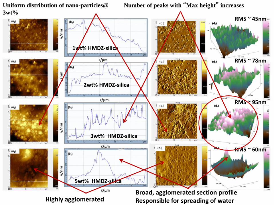
3wt% HMDZ-silica
5wt% HMDZ-silica
1wt% HMDZ-silica
Highly agglomeratedBroad, agglomerated section profileResponsible for spreading of water
RMS ~ 95nm
RMS ~ 60nm
RMS ~ 78nm
2wt% HMDZ-silica
RMS ~ 45nm
Uniform distribution of nano-particles@
3wt%
Number of peaks with “Max height” increases

Area fraction of solid surface (f) can be calculated from Cassie- Baxter equationCosθr = f(Cosθs +1) -1 ,
θr (120⁰, 118⁰, 122⁰ and 125⁰ ) and θs (70⁰) are contact angles of rough and smooth surface
Low value of f for HMDZ implies that modification resulted in exposure of water droplets to comparatively larger portion of air and offers high resistance to wettability which supports high values of contact angle and sliding angle
f=0.37
f=0.39 f=0.35 f =0.31
Maximum number of air pockets

Sliding ability of the coatings
One of the limitation of the formulations made for enhancing hydrophobicity such as fluro addition or fluro + nano-ZnO, the sliding angle was not good ( Wenzel Stage) – where, though we get hydrophobic effect however the beed is struck betwwen roughness groves, hence does not slide.
So in order to improve the sliding angle, the nano particles added must be modified hydrophobically by using various silane precursor, such as HMDZ ( hexamethyl disilazane, DDS – dimethyl dichlroSilane etc.) – Cassie State
Though we modified ZnO by oelic acid and TEOS, but results were not effective.

Mechanism of Hydrophobicity
Once the surface is in Cassie State, its sliding angle is also good and helps in Lower sliding angle and aids for Self Cleaning
CosƟw = Ƴ Cos Ɵv CosƟcb = Ƴf f Cos Ɵv +f-1

Work of adhesion (W) estimates the ease with which
water drops moves on the surface
W=γLAf(1+cosθ)
Neat Sol (w) = 97.95mN/m and HMDZ-FE sol (W)
11.31mN/m.
The decline of W from 97.95mN/m for neat sol-gel to
11.31mN/m for HMDZ-FE composite sol-gel coating
indicates that the water droplets are partially suspended on a
layer of air decreasing the interaction between the solid and
liquid phases.
Furthermore, mixed state can better explain the results
because the contact angle of 125° achieved cannot be
rationalized by the Cassie-Baxter scenario and small sliding
angle of 15° which cannot be explained by Wenzel scenario
Hence both, surface roughness (93nm) due to HMDZ
silica particles and low energy of perfluoro groups which
migrate towards the surface were responsible for enhanced
hydrophobic properties.

wood Card Board
Fabric
PaperConcrete
Glass
Fabric

Proposed mechanism of GPTMS and TEOS polymerization and condensation reaction.
Further crosslinking with HMMM
Non Fluro Approach


Composition of Various Sols TriedSample
DesignationGPTMS HDTMS TEOS
A 0.5 1.5 8
B 2 2 6
C 1 3 6
D 1 3 8
E 1 3 12
Hexadecyltrimethoxysilane

PERFORMANCE OF COATING
• Coating has complete transmittance; same as glass
• Tested by UV-Visible Spectroscopy
0
10
20
30
40
50
60
70
80
90
100
200 250 300 350 400 450 500 550 600 650 700 750 800 850 900
% T
RA
NSM
ITTA
NC
E
FREQUENCY (1/cm)
COMPARISON OF TRANSMITTANCE OF LIGHT
Glass
SAMPLE 6
• Coating has good adherence and life
• Contact angle of 109°

Applications
Glass on Buildings
Solar Panels
furniture


Where we stand today and what we have to do move forward?
Industrialization of such products and their acceptability by users.
Manufacturing in big volumes.
Durability of the functionality – it is one of the biggest concrn.
Cost

Acknowledgements
• Ruchi Grover- Ph.D
• Karan Thanewala
• Manish Bhadhu
• Vijay Kharod
• K.Rajesh- Ph.d