coating defects detection, causes and cures · coating defects detection, causes and cures edward...
TRANSCRIPT

Coating Defects Detection, Causes And Cures
Edward D. CohenEd Cohen Consulting
Timothy A. PottsDark Field Technologies, Inc.

Presentation Topics
• Purpose of talk– Effective use of surface inspection systems
• Defects; Causes and Cures• Inspection System Overview.
– Lasers and Cameras.– Typical architecture.– Software and data mining.

Importance of Defect ReductionThe Role of Automatic Inspection
• Concurrent benefits– Maximize line speed, quality AND yields
WHILE SIMULTANEOUSLY– Minimizing manpower, scrap, customer returns.
• Wide variety of defects in coating and metallizing– Voids, streaks, chatter, fibers, gels, spots, dimples, contaminants.– Substrate and coated stock.
• On-line inspection systems can monitor process– Locate defects, identify, mark location.– Process control; locate after a coating operation.– Quality assurance; locate at the end of the line to verify quality of
shipped roll/sheet.– More effective and consistent than manual inspection.– Real-time.– Cost effective.

Effective Use Multistep Procedure
• Specifying System• Purchase and install• Defect(s) detected• Defect characterization
– Type ,size, shape, “name”• Defect map• Historical database• Experiments• Implement changes

Getting the Optics RightUnderstanding the Optical Challenge
Understand the manual inspection process.How many different inspection setups?
Cross polarizers
Low angle reflection
Direct transmission
Zebra Target
Indirect inspection
Eachinspection setup implies a uniqueoptical channel.

Optical Channels
• An Optical Channel is a “view”.• Bright field optical channels detect which
change light intensity (contaminants, stains, pinholes, streaks, voids).
• Dark field optical channels detect defects which change light path, scatter, diffusion(scratches, gels, streaks, voids).
• Laser and camera technologies have unique strengths and weaknesses; the optical solution must match the detection requirements.

Presentation Topics
• Purpose of talk– Effective use of surface inspection systems
• Defects; Causes and Cures• Inspection System Overview.
– Lasers and Cameras.– Typical architecture.– Software and data mining.

Effective Use Requires Multistep Procedure
• Specifying System• Purchase and install• Defect(s) detected• Defect characterization
– Type ,size, shape, “name”• Defect map• Historical database• Experiments• Implement changes

• Before buying system– Accurate yield analysis
• Identify main defects to be detected– Know highest loss categories– $ loss
– Line speed range– Test samples
• Extensive defect samples, various sizes, Jargon names• Prioritize Must ,Wants • Defects or product anomalies to ignore
Specifying System

Defects: Causes and Cures
• Bright field defects.– Coating Pinholes on film.– Streaks.
• Dark field defects.– Substrate scratches.– Coating disturbances.
• Multiple channel defects.– Coating voids, optical film.– Gels.
• Repeat defects and defect clusters.• Sizing and classification.

Defect Signal
Scan Line
Zoomed
Coating Pinhole, 50 microns
Laser detection and images

Coating Pinhole on FilmCauses and Cures
• Description– Tiny clear spots indicating the absence of a coated layer– Size differentiates from bubbles
• Much smaller• Typical causes:
– Rupture of liquid coating caused by contamination• Dirt, slivers etc. on surface or in coating solution
– Picking of coating by roll– Drying stresses & non-uniform flow rupturing the coating
• Cures– Clean substrate,– Filter coating solution– Uniform drying

Coating Streak on PET
Subtle Severe
Fiber
Laser detection and images
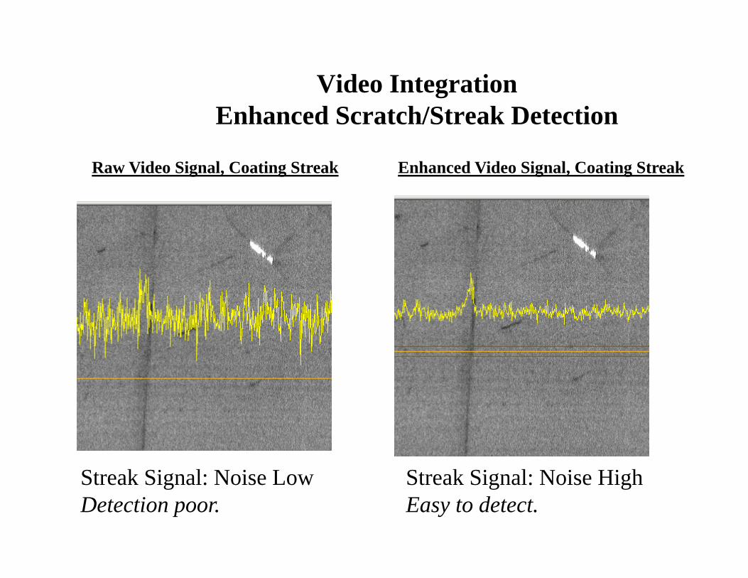
Raw Video Signal, Coating Streak Enhanced Video Signal, Coating Streak
Video IntegrationEnhanced Scratch/Streak Detection
Streak Signal: Noise LowDetection poor.
Streak Signal: Noise HighEasy to detect.

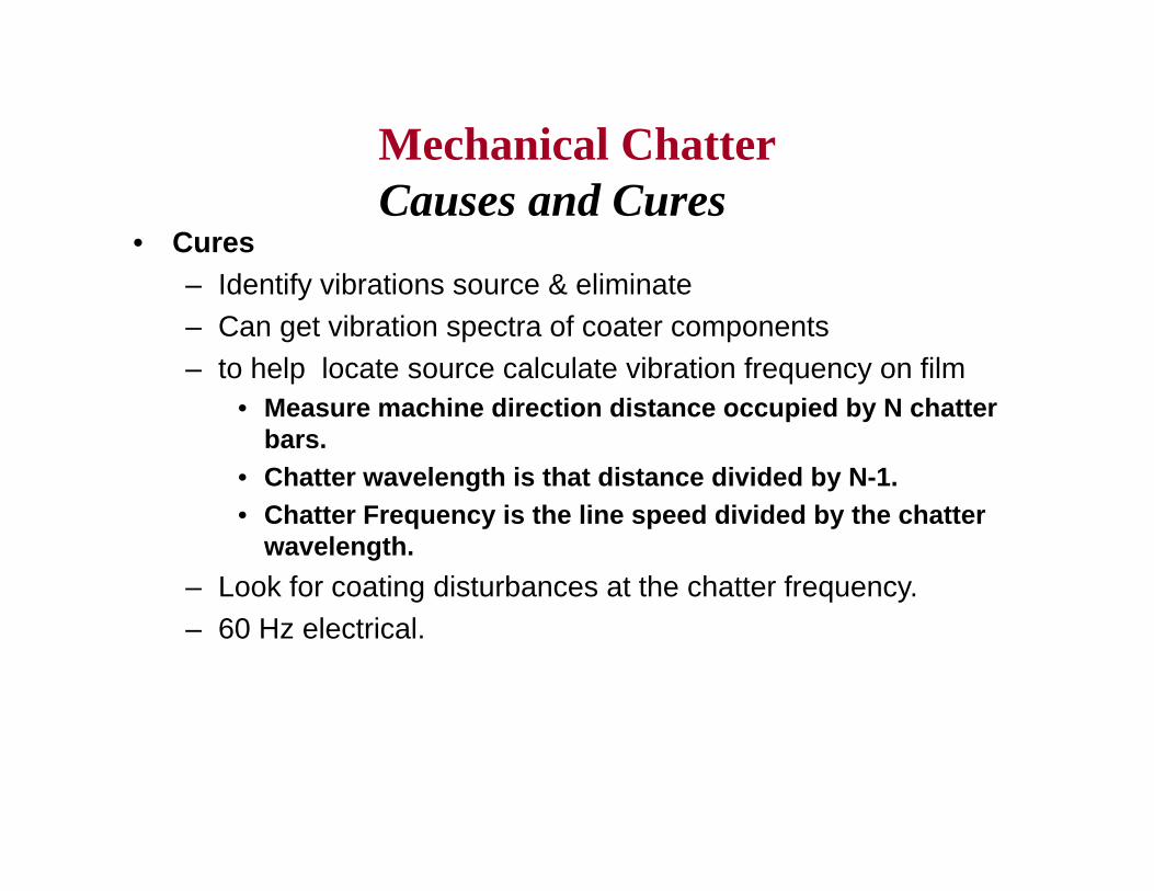
• Cures– Identify vibrations source & eliminate– Can get vibration spectra of coater components– to help locate source calculate vibration frequency on film
• Measure machine direction distance occupied by N chatter bars.
• Chatter wavelength is that distance divided by N-1.• Chatter Frequency is the line speed divided by the chatter
wavelength.– Look for coating disturbances at the chatter frequency.– 60 Hz electrical.
Mechanical ChatterCauses and Cures

Coating Streaks on FilmCures
Get Defect Map: Full map, Md histogram, Td positions.
Intermittent Streak
Lane 6, Streak Histogram
Lane 6, Streak
Repeating voids

Coating Streaks on FilmCures
• Start troubleshooting• Clear bead and observe
– if bubbles or contamination• Reset gap• Purge lines of air• Check lips to see if knicked or build-up• System should show when cleared and if
improvement.

10µm wide Substrate ScratchDark Field Defect
Bright Field Dark Field
Scratch does not absorb lightNo bright field signal.
Scratch scatters lightStrong dark field signal.
Laser images

• Linear gouges in coating– Can be short or long length– Differ from streaks edges ragged
• Caused by– Contamination on roller scratches coating– Difference in roll and web speed
• Cures– Clean all rolls in contact with web– Insure no rolls slipping
ScratchesCauses and Cures
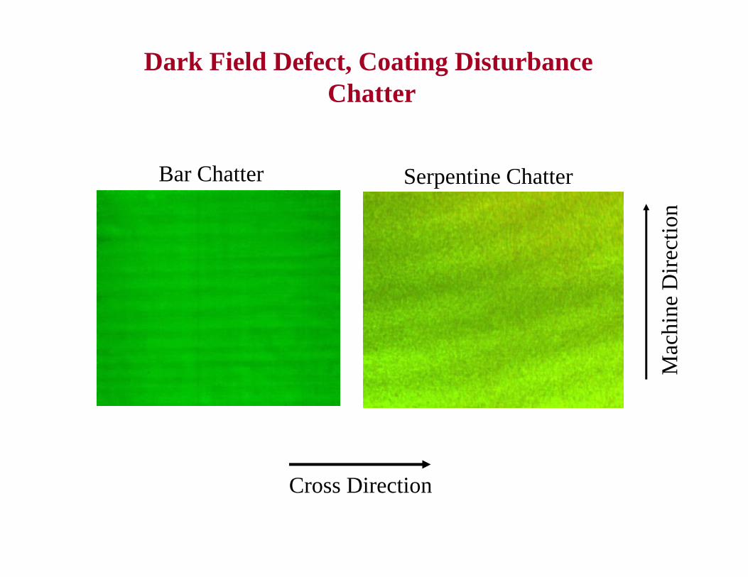
Dark Field Defect, Coating DisturbanceChatter
Cross Direction
Mac
hine
Dire
ctio
n
Bar Chatter Serpentine Chatter

• Series of irregular Td bars– Not as repetitive or straight as mechanical chatter
• Causes:– Hydrodynamic instability in coating bead – Operating outside of the stability region– Wetting effects on substrate
• Cures:– Correct process conditions to operate in stable region– Control viscosity/temperature– Maintain optimum applicator settings– Surface treat substrate for improved wetabbility
Serpentine ChatterCauses and Cures

• Mechanical Chatter Straight Td bars– Slight variation in coating weight
• Causes– Mechanical vibrations from pumps, rolls,drives, h&v
transmitted to coating bead– inducing vibrations in bead,
• Which effect coating weight causing bands.– Chatter on substrate coating
• Can also appear as chatter in final coating
Mechanical ChatterCauses and Cures
• Cures– Identify vibrations source & eliminate– Can get vibration spectra of coater components– to help locate source calculate vibration frequency on film
• Measure machine direction distance occupied by N chatter bars.
• Chatter wavelength is that distance divided by N-1.• Chatter Frequency is the line speed divided by the chatter
wavelength.– Look for coating disturbances at the chatter frequency.– 60 Hz electrical.
Mechanical ChatterCauses and Cures

Multiple Channel Defect, 50 µm optical film Bright Field AND Dark Field
Bright Field Dark Field
Scan line
VideoSignal
Both bright field and dark field are required for defect classification.
Presentation Topics
• Purpose of talk– Effective use of surface inspection systems
• Defects; Causes and Cures• Inspection System Overview.
– Lasers and Cameras.– Typical architecture.– Software and data mining.

Lasers and CamerasAlternative Inspection Technologies
Laser Systems Camera Systems
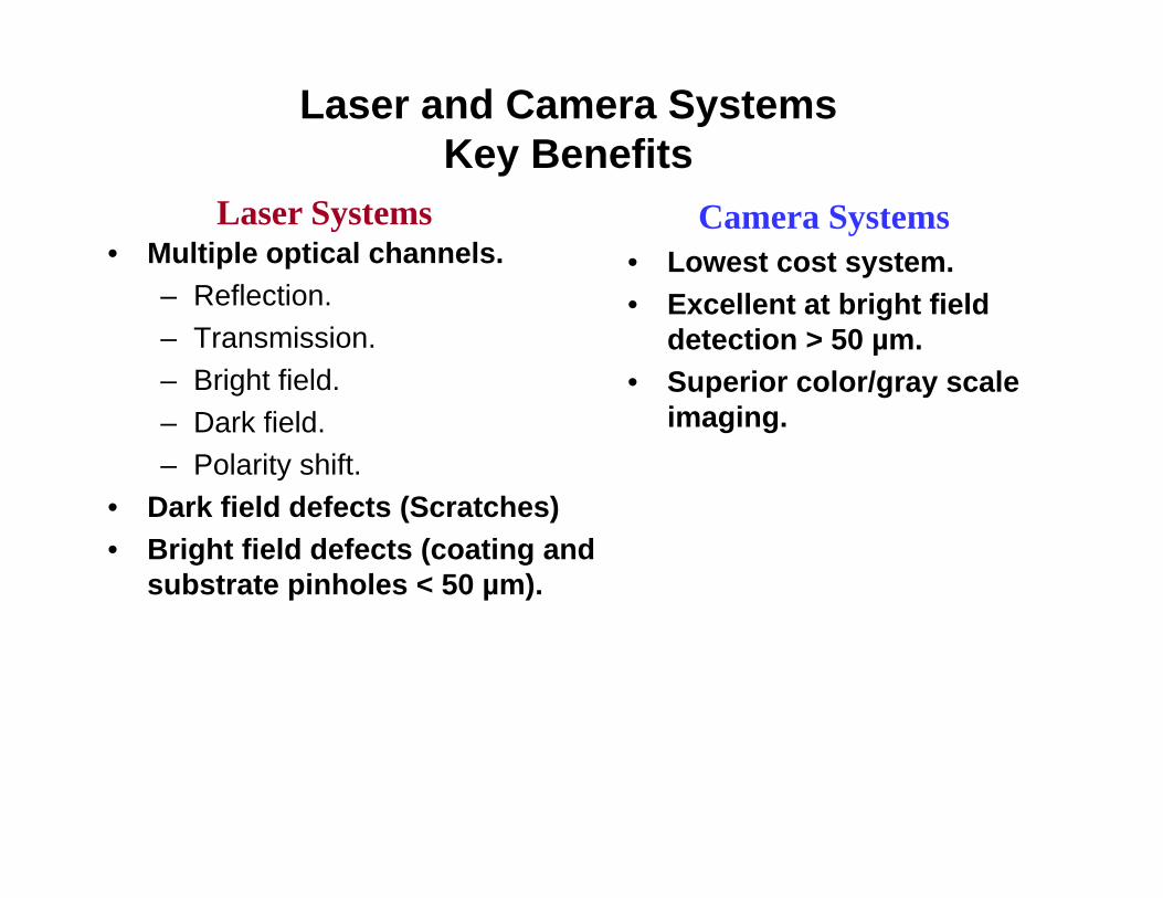
Laser and Camera SystemsKey Benefits
• Multiple optical channels.– Reflection.– Transmission.– Bright field.– Dark field.– Polarity shift.
• Dark field defects (Scratches)• Bright field defects (coating and
substrate pinholes < 50 µm).
• Lowest cost system.• Excellent at bright field
detection > 50 µm. • Superior color/gray scale
imaging.
Laser Systems Camera Systems

Typical System Architecture
Cameras
Illumination Operator Station
ProcessingConsole
Ethernetlink
Defect data, data base
& images for each roll.
BrightFieldDark
Field
Bright Field
TelecentricLaserScanner
Coated Film
VPN Link
Digital I/O’s (Start/stop roll, markers, alarms)

Defect Detected
• Defect map shows location on web– Defect location marked on web– Determine if random or patterned– Md & Td Location
• Insures correct defect worked on
• In some cases will lead directly to cure

Software and Data Mining• Defect map.• Transverse direction (Td) and Machine direction
(Md) histograms.• Data file for each roll, can be recalled at a later
date; defects, sizes, locations, alarms, etc.• Roll optimization; input roll length desired from each
slit width and number of allowable defects; system locates the slit width locations.
• Data mining: Utilize on-board statistical package or third party software for customized analyses and reports; Excel compatible data bases, SQL.

Roll Repeats
• Small spot defects in the machine direction.• From roll contamination• Repeat at a fixed frequency• Defect Map will give you
– Repeat spacing – Location on substrate
Repeat intervalDimple on film
Coating skips on film.

Roll Repeats
• From contamination on roll surface– Disturbing coating
• Measure distance between spots– Equal circumference of dirty rolls
• Measure Td location– Where to look on roll
• Cure – clean rolls– Insure film dry

Substrate Defects
• Often oil, dirt or contamination on substrate will give defect when coated.
• Visually defect appears below coating• In that case run clear substrate and get a defect map.• If it matches coated defect Map • Substrate is the cause
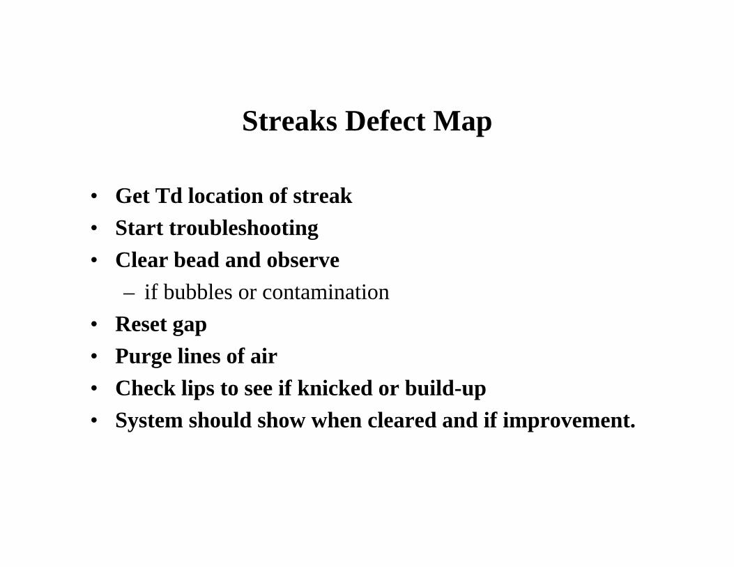
Streaks Defect Map
• Get Td location of streak• Start troubleshooting• Clear bead and observe
– if bubbles or contamination• Reset gap• Purge lines of air• Check lips to see if knicked or build-up• System should show when cleared and if improvement.

Thank you!Timothy A. Potts
Dark Field Technologies, [email protected]
Edward D. CohenEd Cohen Consulting