coastal engineering manual – part i · 2019-08-04 · department of the army em 1110-2-1100 u.s....
TRANSCRIPT

ENGINEER MANUAL
EM 1110-2-1100 (Part I)1 August 2008 (Change 2)
US Army Corpsof Engineers
ENGINEERING AND DESIGN
Coastal Engineering Manual – Part I
DEPARTMENT OF THE ARMY EM 1110-2-1100 U.S. Army Corps of Engineers CECW-EW Washington, DC 20314-1000 Manual No. 1110-2-1100 30 April 2002
Engineering and Design COASTAL ENGINEERING MANUAL
1. Purpose. The purpose of the Coastal Engineering Manual (CEM) is to provide a comprehensive technical coastal engineering document. It includes the basic principles of coastal processes, methods for computing coastal planning and design parameters, and guidance on how to formulate coastal flood studies, shore protection, and navigation projects.
2. Applicability. This manual applies to all HQUSACE elements and all USACE commands having Civil Works and military design responsibilities. 3. Discussion. The CEM is divided into two major subdivisions: science-based and engineering-based. The science subdivision is further divided into three parts. The first part, “Coastal Hydrodynamics,” leads the reader from the fundamental principles of wave theory and ocean wave generation through the process of wave transformation as the wave form approaches and reacts with the shore including water-level variations and currents. The second part, “Coastal Sediment Processes,” addresses longshore and cross-shore transport as well as shelf, and wind transport processes. The third part, “Coastal Geology,” covers geomorphology, coastal classification, and morphodynamic processes on sandy shores. The engineering-based subdivision is oriented toward a project-type approach, rather then the individual structure design and is divided into two parts. The first one, “Coastal Planning and Design,” provides information on the design process and selection of appropriate type of solution to various coastal problems. The second part, “Design of Coastal Project Elements,” provides engineering guidance on materials, fundamentals of design, and reliability. 4. Distribution Statement. Approved for public release, distribution unlimited. FOR THE COMMANDER: 1 Appendix ROBERT CREAR Appendix A - Glossary Colonel, Corps of Engineers Chief of Staff This manual supersedes Shore Protection Manual, 1984; EC 1110-2-289, 30 September 1996; EC 1110-2-292, 31 March 1998; EM 1110-2-1004, 30 November 1993; EM 1110-2-1412, 15 April 1986; EM 1110-2-1414, 7 July 1989; EM 1110-2-1502, 20 August 1992; EM 1110-2-1616, 31 January 1991; EM 1110-2-1617, 20 August 1992; EM 1110-2-1618, 28 April 1995; EM 1110-2-2904, 8 August 1986; EM 1110-2-3301, 31 May 1995.

CECW-EH
Manual No. 111 0-2-11 00
DEPARTMENT OF THE ARMY U.S. Army Corps of Engineers Washington, DC 20314-1000
Engineering and Design COASTAL ENGINEERING MANUAL
EM 1110-2-1100 Change 1
31 July 2003
1. Purpose. The purpose of the Coastal Engineering Manual (CEM) is to provide a comprehensive technical coastal engineering document. It includes the basic principles of coastal processes, methods for computing coastal planning and design parameters, and guidance on how to formulate coastal flood studies, shore protection, and navigation projects. This Change 1 to EM 1110-2-1100, 30 April 2003, includes the following changes and updates:
a. Part I-4. Incorporates new chapter titles. b. Part II-1. Formulas corrected. c. Part II -2. Numerous changes to formulas, coefficients, and figures. d. Part II-4. New findings on the subject matter have been added. e. Part III-1. Table and figure improved. f Part III-2. References corrected. g. Appendix A. Additional terms added and some definitions modified.
2. Applicability. This manual applies to all HQUSACE elements and all USACE commands having Civil Works and military design responsibilities.
3. Discussion. The CEM is divided into six parts in two major subdivisions: science-based and engineering-based. The first four parts of the CEM and an appendix were issued in 30 April 2002. These included:
Part I, "Introduction" Part II, "Coastal Hydrodynamics" Part III, "Coastal Sediment Processes" Part IV, "Coastal Geology" Appendix A, "Glossary"
The engineering-based subdivision is oriented toward a project-type approach and is divided into two parts. Part V, "Coastal Project Planning and Design," is published separately with the same date as this change. The text and figures provide information on the design process and selection of appropriate types of solution to various coastal problems. Part VI, "Design of Coastal Project Elements," which provides engineering guidance on materials, fundamentals of design, and reliability, is in preparation.

EM 1110-2-1100 Change 1 31 Jul 03
4. Distribution Statement. Approved for public release, distribution unlimited.
5. Substitute the following pages:
Chapter 1-4 II-1 II-2 II-4 III-1 III-2 Appendix A
FOR THE COMMANDER:
Remove Page 1-4-2 and 1-4-3 II-1-89 II-2-i thru II-2-72 II -4-i thru II -4-3 8 III-1-8 and III-1-22 III-2-103 A-1 thru A-94
Insert Page I-4-2 and I-4-3 II-1-89 II-2-i thru II-2-72 II-4-i thru II-4-40 III-1-8 and III-1-22 III-2-1 03 A-1 thru A-94
MICHAEL J. WALSH Colonel, Corps of Engineers Chief of Staff
2
CECW-CE
Manual No. 111 0-2-11 00
DEPARTMENT OF THE ARMY U.S. Army Corps of Engineers Washington, DC 20314-1000
Engineering and Design COASTAL ENGINEERING MANUAL
EM 1110-2-1100 (Change 2)
1 April 2008
1. Purpose. The purpose of the Coastal Engineering Manual (CEM) is to provide a comprehensive technical coastal engineering document. It includes the basic principles of coastal processes, methods for computing coastal planning and design parameters, and guidance on how to formulate and conduct studies in support of coastal flooding, shore protection, and navigation projects. This Change 2 to EM 1110-2-1100, 1 April2008, includes the following changes and updates:
a. Part I-1. References were checked and some were deleted (Engineer Manuals that are no longer in the USACE inventory).
b. Part I-4. Minor changes were made in the text to better reflect the contents of subsequent parts of the CEM.
c. Part II-I. Figure II-1-9 has been revised; Equations II-1-128, II-1-160, and II-1-161 have been corrected.
d. Part II-2. Equations II-2-4, II-2-5, and II-2-32 have been corrected along with other errors reported by various users.
e. Part II-5. References were checked and some were deleted (Engineer Manuals that are no longer in the USACE inventory).
f Part II-6. The value of"e" used in Eq. II-6-28 has been corrected. g. Part II-7. The table of contents was corrected. A new section, II-7-11, Note to Users,
Vessel Buoyancy, was added at the end ofthe chapter. h. Part III-3. Corrections have been made to format and spelling. Different plots were added
to Figures III-3-24 and III-3-26. i. Part IV -1. Corrections have been made to references. j. Part V -1. Citation of an Engineer Regulation has been corrected. k. Part V-2. Citation of references has been changed, web pages with sources of wind and
wave data have been added. Some minor text changes have also been made. l. Part V-3. Citations of unpublished reports or personal communications have been
deleted, and links to other figures or parts of the CEM have been checked and corrected. m. Part V -4. Minor text changes, corrections to references and Figure V -4-1. n. Part V-5. Links to other parts of the CEM that were planned but never written have been
deleted.
2. ApplicabHity. This manual applies to all HQUSACE elements and all USACE commands having Civil Works and military design responsibilities.
EM 1110-2-1100 (Change 2) 1 Apr 08
3. Discussion. The CEM is divided into five parts in two major subdivisions: science-based and engineering-based. The first four parts of the CEM and Appendix A compose the sciencebased subdivision:
Part I, "Introduction" Part II, "Coastal Hydrodynamics" Part III, "Coastal Sediment Processes" Part IV, "Coastal Geology" Appendix A, "Glossary"
The engineering-based subdivision is oriented toward a project-type approach, Part V, "Coastal Project Planning and Design."
4. Distribution Statement. Approved for public release, distribution unlimited.
5. Note to Users. Revised chapters are dated 1 April2008. Readers need to download the entire new chapters and discard earlier versions in their possession.
FOR THE COMMANDER:
~l~ Colonel, Corps of Engineers Chief of Staff
2

Introduction I-1-i
Chapter 1 EM 1110-2-1100INTRODUCTION (Part I)
1 August 2008 (Change 2)
Table of Contents
PageI-1-1. Purpose and Scope . . . . . . . . . . . . . . . . . . . . . . . . . . . . . . . . . . . . . . . . . . . . . . . . . . . . . . . I-1-1
I-1-2. Applicability . . . . . . . . . . . . . . . . . . . . . . . . . . . . . . . . . . . . . . . . . . . . . . . . . . . . . . . . . . . . . I-1-1
I-1-3. Definitions . . . . . . . . . . . . . . . . . . . . . . . . . . . . . . . . . . . . . . . . . . . . . . . . . . . . . . . . . . . . . . . I-1-1
a. Coastal . . . . . . . . . . . . . . . . . . . . . . . . . . . . . . . . . . . . . . . . . . . . . . . . . . . . . . . . . . . . . . . . . I-1-1b. Coastal engineering . . . . . . . . . . . . . . . . . . . . . . . . . . . . . . . . . . . . . . . . . . . . . . . . . . . . . . . I-1-1c. Coastal science . . . . . . . . . . . . . . . . . . . . . . . . . . . . . . . . . . . . . . . . . . . . . . . . . . . . . . . . . . I-1-2
I-1-4. Bibliography . . . . . . . . . . . . . . . . . . . . . . . . . . . . . . . . . . . . . . . . . . . . . . . . . . . . . . . . . . . . . I-1-2
I-1-5. References . . . . . . . . . . . . . . . . . . . . . . . . . . . . . . . . . . . . . . . . . . . . . . . . . . . . . . . . . . . . . . . I-1-2
I-1-6. Acknowledgments . . . . . . . . . . . . . . . . . . . . . . . . . . . . . . . . . . . . . . . . . . . . . . . . . . . . . . . . I-1-4

EM 1110-2-1100 (Part I)1 Aug 08 (Change 2)
Introduction I-1-1
Chapter I-1Introduction
I-1-1. Purpose and Scope
The Coastal Engineering Manual (CEM) assembles in a single source the current state-of-the-art in coastalengineering to provide appropriate guidance for application of techniques and methods to the solution of mostcoastal engineering problems. The CEM provides a standard for the formulation, design, and expectedperformance of a broad variety of coastal projects. These projects are undertaken to provide or improvenavigation at commercial harbors, harbor works for commercial fish handling and service facilities, andrecreational boating facilities. As an adjunct to navigation improvements, shore protection projects are oftenrequired to mitigate the impacts of navigation projects. Beach erosion control and hurricane or coastal stormprotection projects provide wave damage reduction and flood protection to valuable coastal commercial,urban, and tourist communities. Environmental restoration projects provide a rational layout and provenapproach to restoring the coastal and tidal environs where such action may be justified, or required asmitigation to a coastal project’s impacts, or as mitigation for the impact of some previous coastal activity,incident, or neglect. As the much expanded replacement document for the Shore Protection Manual (1984)and several other U.S. Army Corps of Engineers (USACE) manuals, the CEM provides a much broader fieldof guidance and is designed for frequent updates.
I-1-2. Applicability
This manual is applicable to U. S. Army Corps of Engineers (USACE) Commands having civil worksresponsibility. It is anticipated that the comprehensive scope and instructions of this manual will warrant itsuse by a broad spectra of coastal engineers and scientists beyond the bounds of the USACE. Although thisbroad application has been considered throughout the development of the CEM, some sections are specificto the mission, authority, and operation of the USACE.
I-1-3. Definitions
Definitions are listed throughout the manual when terms are first introduced. In addition, a glossary of termsis provided in the appendix, and Table IV-1-1 lists definitions of common coastal geologic features.However, a few basic definitions will help the novice to better understand and grasp the purpose and scopeof the CEM. Part IV, Chapter 2 defines types of coastal structures.
a. Coastal. Referring to the zone where the land meets the sea, a region of indefinite width that extendsinland from the sea to the first major change in topography. In this manual, “coastal” will refer to shores thatare influenced by wave processes (oscillatory flow dynamics). Bays, and lakes, and estuaries are included,but rivers, primarily influenced by generally unidirectional currents, are generally beyond the scope of thismanual. Estuaries, including that part of rivers subject to the ebb and flow of the tide are covered by thismanual.
b. Coastal engineering. One of several specialized engineering disciplines that fall under the umbrellaof civil engineering. It is a composite of many physical science and engineering disciplines havingapplication in the coastal area. It requires the rational interweaving of knowledge from a number of technicaldisciplines to develop solutions for problems associated with natural and human induced changes in the
EM 1110-2-1100 (Part I)1 Aug 08 (Change 2)
I-1-2 Introduction
coastal zone, the structural and non-structural mitigation of these changes, and the positive and negativeimpacts of possible solutions to problem areas on the coast. Coastal Engineers may utilize contributions fromthe fields of geology, meteorology, environmental sciences, hydrology, physics, mathematics, statistics,oceanography, marine science, hydraulics, structural dynamics, naval architecture, and others in developingan understanding of the problem and a possible solution. The Coastal Engineer must consider the processespresent in the area of interest such as:
• Environmental processes (chemical, ecological).
• Hydrodynamics processes (winds, waves, water level fluctuations, and currents).
• Seasonal meteorological trends (hurricane season, winter storms).
• Sediment processes (sources, transport paths, sinks, and characteristics).
• Geological processes (soil and strata characteristics, stable and migrating sub-aerial and sub-aqueousfeatures, rebounding or subsiding surfaces).
• Long-term environmental trends (sea level rise, climate change).
• Social and political conditions (land use, development trends, regulatory laws, social trends, publicsafety, economics).
Harbor works, navigation channel improvements, shore protection, flood damage reduction, andenvironmental preservation and restoration are the primary areas of endeavor.
c. Coastal science. This field is a suite of interdisciplinary technologies applied to understandingprocesses, environments, and characteristics of the coastal zone. Coastal Engineers use these understandingsto develop physical adaptations to solve problems and enhance the human interface with the coast.
I-1-4. Bibliography
Technical and scientific literature cited in each chapter is listed in the chapter references.
I-1-5. References
The following are official USACE engineer regulations (ER), engineer manuals (EM), engineer pamphlets(EP), and technical manuals (TM) found in the bibliographies following each chapter. They are highlightedhere for easy USACE use.
TM 5-850-1Engineering and Design of Military Ports
ER 1105-2-100Planning Guidance Notebook
EP 1165-2-1Digest of Water Resources Policies and Authorities

EM 1110-2-1100 (Part I)1 Aug 08 (Change 2)
Introduction I-1-3
EM 1110-1-1802Geophysical Exploration for Engineering and Environmental Investigations
EM 1110-1-1804Geotechnical Investigations
EM 1110-2-1204Environmental Engineering for Coastal Shore Protection
EM 1110-2-1415Hydrologic Frequency Analysis
EM 1110-2-1613Hydraulic Design of Deep-Draft Navigation Projects
EM 1110-2-1615Hydraulic Design of Small Boat Harbors
EM 1110-2-1906Laboratory Soils Testing
EM 1110-2-2301Test Quarries and Test Fills
EM 1110-2-2302Construction with Large Stone
EM 1110-2-5025Dredging & Dredged Material Disposal
EM 1110-2-5026Beneficial Uses of Dredged Material
EM 1110-8-1 (FR)Winter Navigation on Inland Waterways

EM 1110-2-1100 (Part I)1 Aug 08 (Change 2)
I-1-4 Introduction
I-1-6. Acknowledgments
Authors of Chapter I-1:
Joan Pope, U.S. Army Engineer Research and Development Center, Vicksburg, Mississippi.John H. Lockhart, Jr., Headquarters, U.S. Army Corps of Engineers, Washington, DC, (retired).
Reviewer:
Andrew Morang, Ph.D., CHL

Coastal Diversity I-2-i
Chapter 2 EM 1110-2-1100COASTAL DIVERSITY (Part I)
30 April 2002
Table of Contents
PageI-2-1. Introduction . . . . . . . . . . . . . . . . . . . . . . . . . . . . . . . . . . . . . . . . . . . . . . . . . . . . . . . . . . . . . . I-2-1
I-2-2. Coastal Areas . . . . . . . . . . . . . . . . . . . . . . . . . . . . . . . . . . . . . . . . . . . . . . . . . . . . . . . . . . . . I-2-1
a. Atlantic North: Glaciated coast . . . . . . . . . . . . . . . . . . . . . . . . . . . . . . . . . . . . . . . . . . . . . . I-2-1b. Atlantic Central and South: Barrier and drowned valley coasts . . . . . . . . . . . . . . . . . . . . . I-2-2c. The Atlantic and Gulf of Mexico: Coral and mangrove coasts . . . . . . . . . . . . . . . . . . . . . . I-2-4d. Gulf of Mexico East: Wetland mangrove, and barrier coasts . . . . . . . . . . . . . . . . . . . . . . . I-2-4e. Gulf of Mexico West: Barrier coast . . . . . . . . . . . . . . . . . . . . . . . . . . . . . . . . . . . . . . . . . . . I-2-6f. Pacific: Sea cliffs and terraced coasts . . . . . . . . . . . . . . . . . . . . . . . . . . . . . . . . . . . . . . . . . I-2-7g. The Bering and Chukchi Seas: Arctic coastal plains and barriers . . . . . . . . . . . . . . . . . . . I-2-8h. The Beaufort Sea: Deltaic coast . . . . . . . . . . . . . . . . . . . . . . . . . . . . . . . . . . . . . . . . . . . . . I-2-9i. Pacific: Volcanic islands . . . . . . . . . . . . . . . . . . . . . . . . . . . . . . . . . . . . . . . . . . . . . . . . . . . I-2-9j. Great Lakes of North America . . . . . . . . . . . . . . . . . . . . . . . . . . . . . . . . . . . . . . . . . . . . . . I-2-11
I-2-3. Stability . . . . . . . . . . . . . . . . . . . . . . . . . . . . . . . . . . . . . . . . . . . . . . . . . . . . . . . . . . . . . . . . . I-2-13
I-2-4. Erosion . . . . . . . . . . . . . . . . . . . . . . . . . . . . . . . . . . . . . . . . . . . . . . . . . . . . . . . . . . . . . . . . . I-2-14
I-2-5. Solutions . . . . . . . . . . . . . . . . . . . . . . . . . . . . . . . . . . . . . . . . . . . . . . . . . . . . . . . . . . . . . . . I-2-16
I-2-6. References . . . . . . . . . . . . . . . . . . . . . . . . . . . . . . . . . . . . . . . . . . . . . . . . . . . . . . . . . . . . . . I-2-24
I-2-7. Acknowledgments . . . . . . . . . . . . . . . . . . . . . . . . . . . . . . . . . . . . . . . . . . . . . . . . . . . . . . . I-2-26

EM 1110-2-1100 (Part I)30 Apr 02
I-2-ii Coastal Diversity
List of FiguresPage
Figure I-2-1. Atlantic coast characteristics . . . . . . . . . . . . . . . . . . . . . . . . . . . . . . . . . . . . . . . . I-2-2
Figure I-2-2. Atlantic coast tide and wave characteristics . . . . . . . . . . . . . . . . . . . . . . . . . . . . . I-2-3
Figure I-2-3. Barrier Island and bay complex, southern Rhode Island . . . . . . . . . . . . . . . . . . . I-2-4
Figure I-2-4. New York Harbor, 1940s . . . . . . . . . . . . . . . . . . . . . . . . . . . . . . . . . . . . . . . . . . . I-2-5
Figure I-2-5. Length of barrier islands and spits in the United States . . . . . . . . . . . . . . . . . . . . I-2-6
Figure I-2-6. Cape Hatteras, North Carolina . . . . . . . . . . . . . . . . . . . . . . . . . . . . . . . . . . . . . . . I-2-7
Figure I-2-7. Hallandale Beach . . . . . . . . . . . . . . . . . . . . . . . . . . . . . . . . . . . . . . . . . . . . . . . . . I-2-8
Figure I-2-8. Gulf of Mexico coastal characteristics . . . . . . . . . . . . . . . . . . . . . . . . . . . . . . . . . I-2-9
Figure I-2-9. Gulf of Mexico tide and wave characteristics . . . . . . . . . . . . . . . . . . . . . . . . . . . I-2-10
Figure I-2-10. East Pass Inlet, Florida . . . . . . . . . . . . . . . . . . . . . . . . . . . . . . . . . . . . . . . . . . . . I-2-11
Figure I-2-11. Morgan Peninsula, Alabama . . . . . . . . . . . . . . . . . . . . . . . . . . . . . . . . . . . . . . . . I-2-12
Figure I-2-12. Dulac, Louisiana . . . . . . . . . . . . . . . . . . . . . . . . . . . . . . . . . . . . . . . . . . . . . . . . . I-2-13
Figure I-2-13. Pacific coast characteristics . . . . . . . . . . . . . . . . . . . . . . . . . . . . . . . . . . . . . . . . I-2-14
Figure I-2-14. Pacific coast tide and wave characteristics . . . . . . . . . . . . . . . . . . . . . . . . . . . . . I-2-15
Figure I-2-15. Pocket beach just north of Laguna Beach, southern California . . . . . . . . . . . . . I-2-16
Figure I-2-16. Mouth of the Siuslaw River, southern Oregon near the town of Florence . . . . . I-2-17
Figure I-2-17. Seattle, located in sheltered Puget Sound . . . . . . . . . . . . . . . . . . . . . . . . . . . . . . I-2-18
Figure I-2-18. Alaska coastal characteristics . . . . . . . . . . . . . . . . . . . . . . . . . . . . . . . . . . . . . . . I-2-19
Figure I-2-19. Hawaiian Islands wave characteristics . . . . . . . . . . . . . . . . . . . . . . . . . . . . . . . . I-2-20
Figure I-2-20. Great Lakes shoreline characteristics . . . . . . . . . . . . . . . . . . . . . . . . . . . . . . . . . I-2-21
Figure I-2-21. Minnesota Point, photographed from Duluty, Minnesota, looking south . . . . . I-2-22
Figure I-2-22. Calumet Harbor, Indiana . . . . . . . . . . . . . . . . . . . . . . . . . . . . . . . . . . . . . . . . . . . I-2-22
Figure I-2-23. Duluth Canal, Minnesota . . . . . . . . . . . . . . . . . . . . . . . . . . . . . . . . . . . . . . . . . . I-2-23
Figure I-2-24. Bluffs about 1 km north of St. Joseph Harbor, eastern Lake Michigan . . . . . . . I-2-24

EM 1110-2-1100 (Part I)30 Apr 02
Coastal Diversity I-2-iii
List of Tables
Table I-2-1. Age and Sandy Shores of the Major Hawaiian Islands . . . . . . . . . . . . . . . . . . . . I-2-12

EM 1110-2-1100 (Part I)30 Apr 02
Coastal Diversity I-2-1
Chapter I-2Coastal Diversity
I-2-1. Introduction
The coasts, or shores, of the world are the margins separating the 29 per cent of the earth that is land fromthe 71 percent that is water. By reworking and often eroding the margins of the land, the seas aid streams,subsurface water, glaciers, and the wind in wearing down the continents. Sediments derived from the landare often transient along the coasts, temporarily forming beaches, bars or islands before coming to rest on thesea floor. There is significant natural diversity in shore types throughout the United States and even greaterdiversity throughout the world (see Part IV for details). Consequently, engineering, development, and policystrategies need to be tailored for each unique region and need to be flexible to changes in the local condition.Coastal engineers, managers, and planners need to be aware of coastal diversity for a number of reasons:
a. The coast is dynamic and constantly evolving to a new condition.
b. The balance and interaction of processes are different in different areas - understanding diversityprovides clues to the critical factors that may affect a particular study site.
c. Different settings imply different erosion and accretion sediment patterns.
d. Analytical tools and procedures may be suitable for a particular setting but totally inappropriate foranother.
e. Similarly, engineering solutions may only be appropriate for certain settings where they will functionproperly.
Shorelines are subject to a broad range of processes, geology, morphology, and land usages. Although winds,waves, water levels, tides, and currents affect all coasts, they vary in intensity and relative significance fromone location to another. Variations in sediment supply and geological setting add to this coastal diversity.A more detailed discussion and analysis of the processes at work along the United States coasts is given byFrancis P. Shepard and Harold R. Wanless in their book Our Changing Coastline (1971).
I-2-2. Coastal Areas
The popular image of a long, straight, sandy beach with a sandy backshore and foreshore, vegetated sanddunes, and gently sloping near shore zone with rhythmic plunging breakers may be the ideal image of thezone where the land meets the sea, but is not the norm along most coasts. Not all coastal areas are sandy, norare all shores dominated by wave action. Some coastal areas have scenic clay bluffs or rocky headlands.Others are shallow mud flats or lush wetlands. For some shores, tidal currents or river discharge dominatesediment transport and the shore character. For other shores, the effects of glaciers, marine life (coral), orvolcanoes may control the geomorphology. Shore materials include transportable muds, silts, sands, shells,gravels, and cobbles, and insitu rock formations or bedrock (erosive and non-erosive). In portions of theUnited States, the coastal area is sinking and gradually becoming permanently inundated; in other areas, newlands are accreting or even rising out of the sea.
a. Atlantic North: Glaciated coast (Figures I-2-1, I-2-2). These coasts are normally deeply indentedand bordered by numerous rocky islands. The embayments usually have straight sides and deep water as a

EM 1110-2-1100 (Part I)30 Apr 02
I-2-2 Coastal Diversity
600 0 600 1200 Kilometers
Igneous bedrock bluffs, rocky islands, shortspits, tidal estuaries, glacial drumlins, hightide range
Reworked till bluffs, short barriers, estuaries, glacial moraine islands
Barriers with open water pondsLarge bays (Chesapeake, Delaware)
Barriers backed by salt marshNumerous inlets (Georgia Bight)Limestone reef outcrops (Florida)
N
Carbonate (coral) withmangrove in protected areas
Boston
ATLANTIC OCEAN
CANADA
Delaware Bay
New York
Chesapeake Bay
Charleston
Figure I-2-1. Atlantic coast characteristics
result of erosion by the glaciers. Uplifted terraces may be common along these coasts that were formerlyweighted down by ice. Abrupt changes in coastal character occur where glacial deposits and particularlyglacial outwash play a dominant role, while in some rocky areas, few glacial erosion forms can be found.Moraines, drumlins, and sand dunes, the result of reworking outwash deposits, are common features.Glaciated coasts in North America extend from the New York City area north to the Canadian Arctic (FiguresI-2-3, I-2-4, IV-2-8, and IV-2-9), on the west coast, from Seattle, Washington, north to the Aleutian Islands,and in the Great Lakes. (Figure IV-2-20) (Shepard 1982).
b. Atlantic Central and South: Barrier and drowned valley coasts. South of the glacial areas beginsthe coastal Atlantic plain, featuring almost continuous barriers interrupted by inlets and by large embaymentswith dendritic drowned river valleys, the largest being Delaware and Chesapeake Bays. The North Americancoastline is reported to include over 10,000 km of barriers, about 33 percent of all barrier coast of the world(Berryhill, Dixon, and Holmes 1969). The United States alone has a total length of 4,900 km of barriers andspits, the longest extent for a single nation (Figure I-2-5 and Table IV-2-3). Extensive wetlands and marshes

EM 1110-2-1100 (Part I)
30 Apr 02
Coastal D
iversityI-2-3
Figure I-2-2. Tide and wave characteristics of the Atlantic coasts. Wave data summarized from National Data Buoy Center buoys. HmO and Tpaveraged from hourly statistics over total period of record from statistics computed by National data Buoy Center. Tide range for indicated stationsfrom statistics presented in NOAA Tide Tables

EM 1110-2-1100 (Part I)30 Apr 02
I-2-4 Coastal Diversity
Figure I-2-3. Barrier Island and bay complex, southern Rhode Island. View looking west towardQuonochontaug Point, a rocky headland with bedrock outcrops. The barrier in the foreground is East Beach,with Block Island Sound to the left and Ninigret Pond to the right. Prominent overwash fans can be seen inthe shallow waters of the pond (April 1977)
mark much of the coast, where sediment and marsh vegetation have partly filled the lagoons behind thebarriers. Some coasts have inland ridges of old barrier islands, formed during interglacial epochs, separatedfrom the modern barrier islands by low marshes or lagoons. The best exhibit of cuspate forelands in theworld extends from the mouth of Chesapeake Bay to Cape Romain, South Carolina (Figure I-2-6). The coastis much straighter south of Cape Romain and the only cuspate foreland is that of Cape Canaveral, Florida.Barrier Islands and drowned valleys continue south to Miami, Florida (Figure I-2-7), except for a brief lengthof coast in the Myrtle Beach, South Carolina, area where the barriers are attached to the coastal plain. Muchof the southeast coast of Florida was extensively filled, dredged, and reshaped in the early 20th century tosupport development (Lenček and Bosher 1998). From Miami around the tip of Florida through Alabama,Mississippi and eastern Louisiana, coastal characteristics alternate between swampy coast and white sandbarriers (Shepard 1982).
c. The Atlantic and Gulf of Mexico: Coral and mangrove coasts. The barrier islands change from quartzsand south of Miami to carbonate-dominated sand, eventually transforming into coral keys and mangroveforest. The Florida Keys are remnants of coral reefs developed during a higher sea level stage of the lastinterglacial period. Live reefs now grow along the east and south side of the keys and the shallows of FloridaBay studded with mangrove islands extending north and west into the Everglades and the Ten ThousandIslands area that comprises the lower Florida Gulf of Mexico coast (Shepard 1982).

EM 1110-2-1100 (Part I)
30 Apr 02
Coastal D
iversityI-2-5
Figure I-2-4. New York Harbor, late 1930s. This drowned river valley system, partly sculpted by glaciers, is one of the world’s finest natural harbors. The USACE has an active role dredging, clearing debris, and maintaining navigability of this great port. View looking north, with Manhattan in thecenter and Brooklyn to the right. Photograph from Beach Erosion Board archives

EM 1110-2-1100 (Part I)30 Apr 02
I-2-6 Coastal Diversity
Figure I-2-5. Length (in km) of barrier islands and spits in the United States. Data measured fromU.S. Geological Survey topographic maps (see Table IV-2-3 for details)
d. Gulf of Mexico East: Wetland mangrove, and barrier coasts (Figures I-2-8, I-2-9). On Florida’s Gulfof Mexico coast, barrier islands begin at Cape Romano and extend north as far as Cedar Keys. Enclosed baysusually have an abundance of mangrove islands and the topography is low with many lakes and marshes.North of Cedar Keys, the barrier islands end. They are replaced by a vast marsh doted with small vegetatedislands. The rock strata in this area are limestone, which, along with the low river gradients and numerousponds or sinkholes, accounts for the absence of sand in the region. Due to its location and the large shallowwater area offshore, little wave energy is present except during rare hurricanes. Some 130 km to thenorthwest, the swamp coast ends. Here the coastal trend changes direction from north-south to east-west, andOchlockonee Bay, with drainage from the southern Appalachian Mountains, provides quartz sand forredevelopment of barrier islands. These sandy islands, with their various openings for access to the lowlandport cities, continue westward as far as the Mississippi River delta (Figures I-2-10 and I-2-11).
Studies of the Mississippi delta indicate that the river has built a series of deltas into the Gulf of Mexicoduring postglacial times and that the Balize Delta (bird foot) is the latest, with an age of about 1500 years.The Bird Foot delta is southeast of New Orleans, lying among a series of old passes that extend for 300 km(186 miles) along the coast. Most of the greater Mississippi delta is marshland and mud flats, with numerousshallow lakes and intertwining channels (Figures I-2-12 and IV-3-9). The principal rivers have built naturallevees along their course. These natural levees are about a meter above the normal water level, but many ofthem have been artificially raised to provide protection to towns and cities from floods. Aquatic plants coverthe marshland, which is remarkable for the huge population of waterfowl it supports. In the areas of old deltalobes, subsidence has left only the natural levees above water in some instances.
e. Gulf of Mexico West: Barrier coast. From western Louisiana, west of the Mississippi Delta marshcoast, toward the southwest, barrier islands become the dominant coastal features. Some of the longest

EM 1110-2-1100 (Part I)30 Apr 02
Coastal Diversity I-2-7
Figure I-2-6. Cape Hatteras, North Carolina, view north. The Atlantic Ocean is to the right, and the bay to theleft of the barrier is Pamlico Sound. The rough water in the foreground is the infamous Diamond Shoals,known as the “Graveyard of the Atlantic.” The bump in the shoreline is the location of the Cape Hatteraslighthouse, which was recently moved inland away from the receding shore. A mature maritime forest hasgrown on the beach ridges in the central portion of the barrier. The forest indicates that this portion of theisland has been stable for several hundred years. Photograph taken February 28, 1993, during the waningstage of an extratropical storm
barrier islands in the world are located along the Texas coast. Padre Island and Mustang Island, combined,extend for 208 km and feature extensive dune fields behind the broad beaches. The dunes rarely rise morethan 10 m in height, and many marshy wash-over deltas have extended into the large lagoons behind thebarriers. The lagoons and estuaries decrease in depth toward Mexico. A large part of Laguna Madre is onlyinundated during flood periods or when the wind blows water from Corpus Christi Bay onto the flats. Riverdeltas are responsible for much of this infilling, resulting in large differences between recent chart depths andthose of 100 years ago (Shepard 1982).
f. Pacific: Sea cliffs and terraced coasts (Figures I-2-13, I-2-14). Low sea cliffs bordered byterraces and a few coastal plains and deltas compose the coasts of southern California. Blocks formprojections into the sea and feature a series of raised terraces such as those at Point Loma, SoledadMountain, and the San Pedro Hills in the Los Angeles area. North of Los Angeles, the Santa MonicaMountains follow the coast. Sea cliffs in this area are actively eroding, particularly in areas where they havebeen cut into alluvium (Figure I-2-15). At Point Conception, the coast trends north-northwest and a different
EM 1110-2-1100 (Part I)30 Apr 02
I-2-8 Coastal Diversity
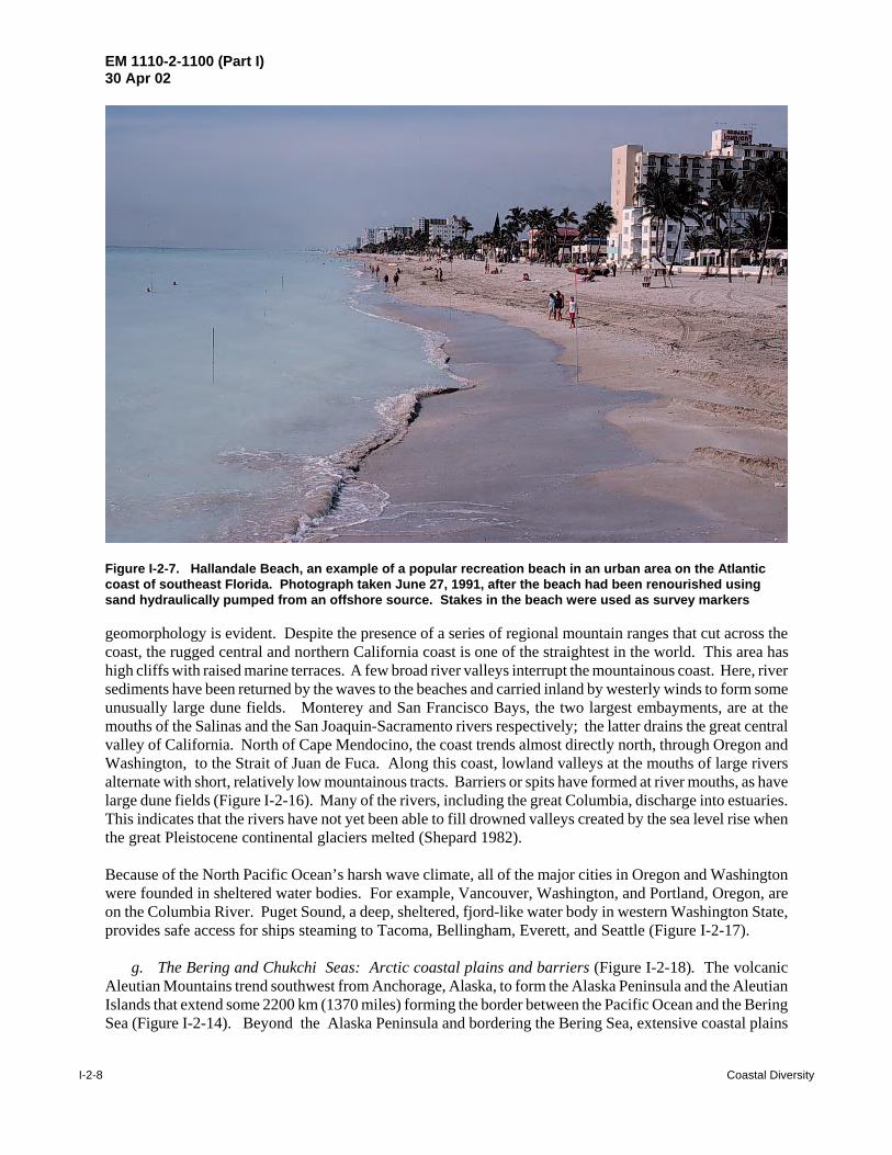
Figure I-2-7. Hallandale Beach, an example of a popular recreation beach in an urban area on the Atlanticcoast of southeast Florida. Photograph taken June 27, 1991, after the beach had been renourished usingsand hydraulically pumped from an offshore source. Stakes in the beach were used as survey markers
geomorphology is evident. Despite the presence of a series of regional mountain ranges that cut across thecoast, the rugged central and northern California coast is one of the straightest in the world. This area hashigh cliffs with raised marine terraces. A few broad river valleys interrupt the mountainous coast. Here, riversediments have been returned by the waves to the beaches and carried inland by westerly winds to form someunusually large dune fields. Monterey and San Francisco Bays, the two largest embayments, are at themouths of the Salinas and the San Joaquin-Sacramento rivers respectively; the latter drains the great centralvalley of California. North of Cape Mendocino, the coast trends almost directly north, through Oregon andWashington, to the Strait of Juan de Fuca. Along this coast, lowland valleys at the mouths of large riversalternate with short, relatively low mountainous tracts. Barriers or spits have formed at river mouths, as havelarge dune fields (Figure I-2-16). Many of the rivers, including the great Columbia, discharge into estuaries.This indicates that the rivers have not yet been able to fill drowned valleys created by the sea level rise whenthe great Pleistocene continental glaciers melted (Shepard 1982).
Because of the North Pacific Ocean’s harsh wave climate, all of the major cities in Oregon and Washingtonwere founded in sheltered water bodies. For example, Vancouver, Washington, and Portland, Oregon, areon the Columbia River. Puget Sound, a deep, sheltered, fjord-like water body in western Washington State,provides safe access for ships steaming to Tacoma, Bellingham, Everett, and Seattle (Figure I-2-17).
g. The Bering and Chukchi Seas: Arctic coastal plains and barriers (Figure I-2-18). The volcanicAleutian Mountains trend southwest from Anchorage, Alaska, to form the Alaska Peninsula and the AleutianIslands that extend some 2200 km (1370 miles) forming the border between the Pacific Ocean and the BeringSea (Figure I-2-14). Beyond the Alaska Peninsula and bordering the Bering Sea, extensive coastal plains

EM 1110-2-1100 (Part I)30 Apr 02
Coastal Diversity I-2-9
400 0 400 Kilometers
GULF OF MEXICO
Texas
Florida
River delta, marsh, muddy sediments, critical erosion in
most areasBarriers and open bays
Mangrove,marsh
Carbonate banks,islands
Yucatan
N
Mississippi R. delta
Figure I-2-8. Gulf of Mexico coastal characteristics
are found with numerous lakes and meandering streams. Only a few mountain ranges extend as points intothe sea. The Yukon River has formed a large delta with many old lobes that form a vast plain connectingsmall, elevated tracts. The oldest is located in the now drowned mouth of the Kuskokwim River. One reasonthis coast differs from the glaciated southern coast of Alaska, is because it was largely ice- free during thePleistocene era. Permafrost becomes more important to the north where it greatly increases the number ofsurface depressions in the summer when it melts forming thaw lakes. Rising above the coastal plain withmountains over 1,000 m, the Seward Peninsula with Norton Sound and the Bering Sea to the south andKotzebbue Sound and the Chukchi Sea to the north provides a great contrast to the adjoining coasts. Northof Kotzebue Sound, barriers and cuspate forelands similar to those of North Carolina border the coast. Thefirst cuspate foreland is the unusual Point Hope. Three more cuspate forelands extend along the coastterminating with Point Barrow, the most northern point of Alaska (Shepard 1982).
h. The Beaufort Sea: Deltaic coast. East of Point Barrow, the coast is dominated by river deltas.Rivers draining the Brooks Range and father east the Mackenzie, draining the northern Canadian Rockies,built these deltas even though the rivers flow only a short period each year. Where the deltas are not activelybuilding into the sea, extensive barrier islands can be found (Shepard 1982). One of the dominant processesin shaping beaches in Alaska is the ride-up of shore ice (Kovacs 1983).

EM 1110-2-1100 (Part I)30 Apr 02
I-2-10 Coastal Diversity
#
#
#
#
#
##
# #
#
#
%
%
%
%%%
%%%
%
1.4
1.2
1
0.80.60.4
Wave Height Hm0 (m)
6.5
6
5.5
5
4.5
Peak Period Tp (sec)
0.75
0.5
0.25
0
-0.25-80-82-84-86-88-90-92-94-96-98
Mean Tide Range (m)
GULF OF MEXICO
200 0 200 400 KilometersNOAA Tide StationsNDBC Buoys
%
#
Longitude
N
TexasFlorida
Figure I-2-9. Tide and wave characteristics of the Gulf Coast
EM 1110-2-1100 (Part I)30 Apr 02
Coastal Diversity I-2-11
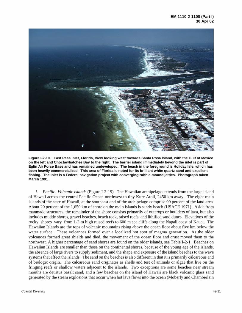
Figure I-2-10. East Pass Inlet, Florida, View looking west towards Santa Rosa Island, with the Gulf of Mexicoon the left and Choctawhatchee Bay to the right. The barrier island immediately beyond the inlet is part ofEglin Air Force Base and has remained undeveloped. The beach in the foreground is Holiday Isle, which hasbeen heavily commercialized. This area of Florida is noted for its brilliant white quartz sand and excellentfishing. The inlet is a Federal navigation project with converging rubble-mound jetties. Photograph takenMarch 1991
i. Pacific: Volcanic islands (Figure I-2-19). The Hawaiian archipelago extends from the large islandof Hawaii across the central Pacific Ocean northwest to tiny Kure Atoll, 2450 km away. The eight mainislands of the state of Hawaii, at the southeast end of the archipelago comprise 99 percent of the land area.About 20 percent of the 1,650 km of shore on the main islands is sandy beach (USACE 1971). Aside frommanmade structures, the remainder of the shore consists primarily of outcrops or boulders of lava, but alsoincludes muddy shores, gravel beaches, beach rock, raised reefs, and lithified sand dunes. Elevations of therocky shores vary from 1-2 m high raised reefs to 600 m sea cliffs along the Napali coast of Kauai. TheHawaiian Islands are the tops of volcanic mountains rising above the ocean floor about five km below thewater surface. These volcanoes formed over a localized hot spot of magma generation. As the oldervolcanoes formed great shields and died, the movement of the ocean floor and crust moved them to thenorthwest. A higher percentage of sand shores are found on the older islands, see Table I-2-1. Beaches onHawaiian Islands are smaller than those on the continental shores, because of the young age of the islands,the absence of large rivers to supply sediment, and the shape and exposure of the island beaches to the wavesystems that affect the islands. The sand on the beaches is also different in that it is primarily calcareous andof biologic origin. The calcareous sand originates as shells and test of animals or algae that live on thefringing reefs or shallow waters adjacent to the islands. Two exceptions are some beaches near streammouths are detritus basalt sand, and a few beaches on the island of Hawaii are black volcanic glass sandgenerated by the steam explosions that occur when hot lava flows into the ocean (Moberly and Chamberlain
EM 1110-2-1100 (Part I)30 Apr 02
I-2-12 Coastal Diversity
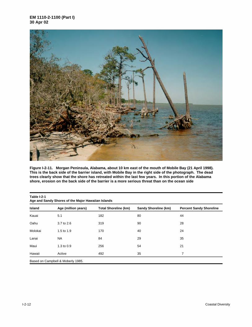
Figure I-2-11. Morgan Peninsula, Alabama, about 10 km east of the mouth of Mobile Bay (21 April 1998). This is the back side of the barrier island, with Mobile Bay in the right side of the photograph. The deadtrees clearly show that the shore has retreated within the last few years. In this portion of the Alabamashore, erosion on the back side of the barrier is a more serious threat than on the ocean side
Table I-2-1Age and Sandy Shores of the Major Hawaiian Islands
Island Age (million years) Total Shoreline (km) Sandy Shoreline (km) Percent Sandy Shoreline
Kauai
Oahu
Molokai
Lanai
Maui
Hawaii
5.1
3.7 to 2.6
1.5 to 1.9
NA
1.3 to 0.9
Active
182
319
170
84 256
492
80
90
40
29
54
35
44
28
24
35
21
7
Based on Campbell & Moberly 1985.
EM 1110-2-1100 (Part I)30 Apr 02
Coastal Diversity I-2-13
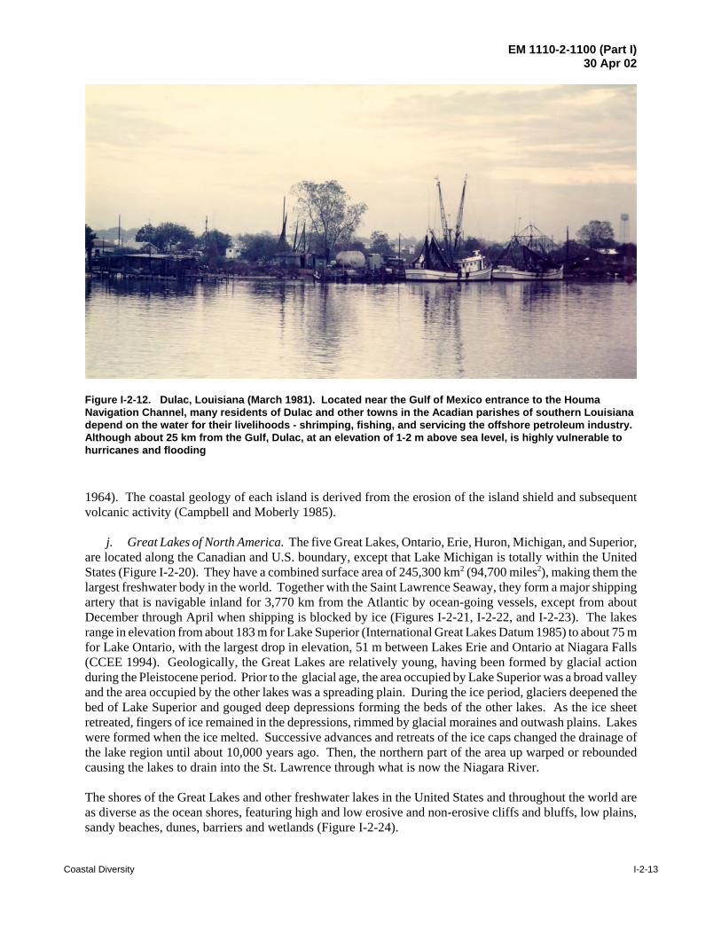
Figure I-2-12. Dulac, Louisiana (March 1981). Located near the Gulf of Mexico entrance to the HoumaNavigation Channel, many residents of Dulac and other towns in the Acadian parishes of southern Louisianadepend on the water for their livelihoods - shrimping, fishing, and servicing the offshore petroleum industry. Although about 25 km from the Gulf, Dulac, at an elevation of 1-2 m above sea level, is highly vulnerable tohurricanes and flooding
1964). The coastal geology of each island is derived from the erosion of the island shield and subsequentvolcanic activity (Campbell and Moberly 1985).
j. Great Lakes of North America. The five Great Lakes, Ontario, Erie, Huron, Michigan, and Superior,are located along the Canadian and U.S. boundary, except that Lake Michigan is totally within the UnitedStates (Figure I-2-20). They have a combined surface area of 245,300 km2 (94,700 miles2), making them thelargest freshwater body in the world. Together with the Saint Lawrence Seaway, they form a major shippingartery that is navigable inland for 3,770 km from the Atlantic by ocean-going vessels, except from aboutDecember through April when shipping is blocked by ice (Figures I-2-21, I-2-22, and I-2-23). The lakesrange in elevation from about 183 m for Lake Superior (International Great Lakes Datum 1985) to about 75 mfor Lake Ontario, with the largest drop in elevation, 51 m between Lakes Erie and Ontario at Niagara Falls(CCEE 1994). Geologically, the Great Lakes are relatively young, having been formed by glacial actionduring the Pleistocene period. Prior to the glacial age, the area occupied by Lake Superior was a broad valleyand the area occupied by the other lakes was a spreading plain. During the ice period, glaciers deepened thebed of Lake Superior and gouged deep depressions forming the beds of the other lakes. As the ice sheetretreated, fingers of ice remained in the depressions, rimmed by glacial moraines and outwash plains. Lakeswere formed when the ice melted. Successive advances and retreats of the ice caps changed the drainage ofthe lake region until about 10,000 years ago. Then, the northern part of the area up warped or reboundedcausing the lakes to drain into the St. Lawrence through what is now the Niagara River.
The shores of the Great Lakes and other freshwater lakes in the United States and throughout the world areas diverse as the ocean shores, featuring high and low erosive and non-erosive cliffs and bluffs, low plains,sandy beaches, dunes, barriers and wetlands (Figure I-2-24).

EM 1110-2-1100 (Part I)30 Apr 02
I-2-14 Coastal Diversity
400 0 400 800 1200 Kilometers
California
Oregon
Washington
MEXICO
CANADA
-San Francisco
Unstable sea cliffs, sand beaches,offshore island provide some sheltering
Rugged, high cliffs, sand-deficient shores.Largest estuary complex:San Francisco Bay
Sea cliffs, sand spits, pocket beaches, exposed to high wave energy.One major river: Columbia
Glacially-modified, gravel pocket beaches, till bluffs.Puget Sound sheltered fromocean waves, ice-free
NPACIFIC OCEAN
Columbia R.
-Seattle
Figure I-2-13. Pacific coastal characteristics
I-2-3. Stability
Not all shores are in equilibrium with the present littoral processes. Shores with a character inherited fromprevious non-littoral processes (i.e., glacial or river deposited materials) maybe doomed to significant ratesof erosion under present conditions, such as the Mississippi delta of Louisiana and portions of theGreat Lakes. Some shores exhibit short-term seasonal or episodic event-driven cyclic patterns of erosion andaccretion (e.g., the southern U.S. Atlantic coast). Other shores demonstrate long-term stability due tobalanced sediment supply and little relative sea level rise influence, such as the west coast of Florida. Forsome shores, very little beach-building material is available, and what little is available may be prone to rapidtransport, either alongshore or offshore (e.g., the Great Lakes). Shores that have been heavily modified byman’s activities usually require a continuing commitment to retain the status quo. Prime examples areNew Jersey, which was extensively modified during the 20th century and is now undergoing several major

EM 1110-2-1100 (Part I)
30 Apr 02
Coastal D
iversityI-2-15
Figure I-2-14. Pacific coast tide and wave characteristics. The southernmost buoy shows high wave period because of the influenceof swell waves and sheltering from wind waves provided by offshore islands

EM 1110-2-1100 (Part I)30 Apr 02
I-2-16 Coastal Diversity
Figure I-2-15. Pocket beach just north of Laguna Beach, southern California (April 1993). Poorlyconsolidated sandstone and conglomerate bluffs in this area are highly vulnerable to erosion, jeopardizingexclusive residential properties. Erosion is caused by storm waves and groundwater runoff
beach fills, and numerous urban areas around the country (Los Angeles, New York, Galveston, Chicago,Miami, Palm Beach). I-2-4. Erosion
In order for one shore to accrete, often some other shore must erode. Erosion is a natural response to thewater and wind processes at the shore, but erosion is only a problem when human development is at risk.Sometimes, man-made alterations to the littoral system, including modifications to sediment sources orsinks, may contribute to the eroded condition. The National Shoreline Study (DOA 1971) found that24 percent of the entire United States shore of 135,000 km (84,000 miles) is undergoing significant erosionwhere human development was threatened. If Alaska, with its 24,800 km. (15,400 miles) of shore is removedfrom the statistic, 42 percent of the United States shore is experiencing significant erosion!
I-2-5. Solutions
There are no absolute rules, nor absolute solutions to the problem of coastal erosion given the dynamic andthe diverse character of the shoreline. No single set of regulations, or single land use managementphilosophy, is appropriate for all coastal situations or settings. The diversity of the coasts requiresconsideration of a variety of solutions when addressing problems in a particular area. Solutions can beclassified into five broad functional classes of engineering or management, as listed in Table I-2-2. Theseoptions are explored in detail in Part V of the CEM.

EM 1110-2-1100 (Part I)30 Apr 02
Coastal Diversity I-2-17
Figure I-2-16. Mouth of the Siuslaw River, southern Oregon near the town of Florence (December 1994; viewlooking south). This and other Federal navigation projects on the Oregon and Washington coasts are difficultand expensive to maintain because of high wave energy and a short construction season. The scale of thesePacific projects is difficult to appreciate from aerial photographs: the Siulslaw rubble-mound jetties, first builtin 1917, are 180 m apart and the north jetty is 2300 m long. The shore in this area consists of long barrier spitsinterrupted with rocky headlands
Table I-2-2Alternatives for Coastal Hazard MitigationFunctional Class Approach Type1. Armoring structures Seawall
BulkheadRevetment - revetment
2. Beach stabilization structures and facilities Breakwaters (including artificial headlands)GroinsSills vegetationGroundwater drainage
3. Beach restoration Beach nourishmentSand passing
4. Adaptation and accommodation Flood proofingZoningRetreat
5. Combinations Structural and restorationStructural and restoration and adaptation
6. Do nothing (no intervention)Abbreviated from CEM Part V, Table V-3-1
EM 1110-2-1100 (Part I)30 Apr 02
I-2-18 Coastal Diversity
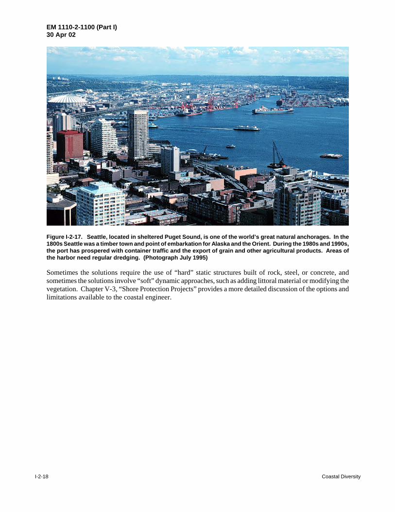
Figure I-2-17. Seattle, located in sheltered Puget Sound, is one of the world’s great natural anchorages. In the1800s Seattle was a timber town and point of embarkation for Alaska and the Orient. During the 1980s and 1990s,the port has prospered with container traffic and the export of grain and other agricultural products. Areas ofthe harbor need regular dredging. (Photograph July 1995)
Sometimes the solutions require the use of “hard” static structures built of rock, steel, or concrete, andsometimes the solutions involve “soft” dynamic approaches, such as adding littoral material or modifying thevegetation. Chapter V-3, “Shore Protection Projects” provides a more detailed discussion of the options andlimitations available to the coastal engineer.

EM 1110-2-1100 (Part I)30 Apr 02
Coastal Diversity I-2-19
#
500 0 500 1000 Kilometers
GULF OFALASKA
CHUKCHI SEA
Aleutian Islands
BEAUFORT SEA
BERINGSEA
PACIFIC OCEAN, ALASKA
Buoy 46008Hm0 = 2.3 mTp (not avail.)
Rugged rocky coasts,
sheltered fjordsmostly ice-free
Active volcanoes
Arctic coastal plains, lakes, gravel barriers,
Yukon delta
Seward P.
Barriers, cuspateforelands River deltas, extensive sand
and gravel barriers
Yukon R.
Figure I-2-18. Alaska coastal characteristics

EM 1110-2-1100 (Part I)30 Apr 02
I-2-20 Coastal Diversity
#
#
##
#
##
%%
%%
%
%
%
300 0 300 Kilometers
1110.5
109.5
9
Long
-152-153-154-155-156-157-158-159-160-161-162-163
Wave Period Tp (sec)
0.8
0.7
0.6
0.5
0.4
Diurnal Tide Range (m)
2.5
2.25
2
1.75
1.5
Wave Height Hm0 (m)
PACIFIC OCEAN, HAWAIIAN ISLANDS
NOAA Tide StationsNDBC Buoys
%
#
Recent volcanicactivity, pocket
beaches of volcanic clastsand carbonate
fragments,exposure to high
wave energy, subject tohurricanes
Kauai
Oahu
Maui
Hawaii
Molokai
Lanai
Youngest island,active volcanoes
N
Niihau
Figure I-2-19. Hawaiian Islands wave characteristics

EM 1110-2-1100 (Part I)30 Apr 02
Coastal Diversity I-2-21
Wisconsin
Michigan
Iowa
OhioIllinois
Pennsylvania
New York
Indiana
Ontario
Quebec
Superior
HuronM
ichi
gan
Erie
Ontario
L. St. Clair
GREAT LAKES, USA-CANADAOver 600 U.S. Federal navigation projects. Deep-draft ocean commerce possible April-November via St. Lawrence Seaway.
Duluth-Superior:major sand spit
Bedrock bluffs, sand-deficient shores, ice-
bound in winter.
Glacial till and sandbluffs, high erosionrate, limited graveland sand beaches
N
200 0 200 400 Kilometers
Glacial till and shale bluffs, variable erosion rate, limited gravel and
sand beaches, fringing marshes
Extensive urban and industrial infrastructure: Lakes Erie, southern Michigan, southern Huron.
Figure I-2-20. Great Lakes shoreline characteristics

EM 1110-2-1100 (Part I)30 Apr 02
I-2-22 Coastal Diversity
Figure I-2-21. Minnesota Point, photographed from Duluth, Minnesota, looking south (November 1994). This bay-mouth sand spit is reputed to be the largest fresh water barrier in the world. It extends from the Wisconsin shorenear Superior to the Minnesota shore at Duluth. St. Louis Bay, to the right, needs regular dredging because ofsilt and sand supplied by the St. Louis River. The northern part of Minnesota Point is developed with residentialproperty. Nearby Duluth and Superior are both major industrial centers, accessible by ocean-going ships
Figure I-2-22. Calumet Harbor, Indiana (September 1985). This is an example of the industrial infrastructurefound in many of the Great Lakes cities that thrived from the 1800s until the 1970s. Many of these steel mills arenow closed, but some of the sites are being redeveloped for other purposes. Calumet is a Federal navigationproject. The concrete cap on the breakwater in the foreground has shifted, indicating some damage to theunderlying wood crib (originally built in the 1890s)
EM 1110-2-1100 (Part I)30 Apr 02
Coastal Diversity I-2-23
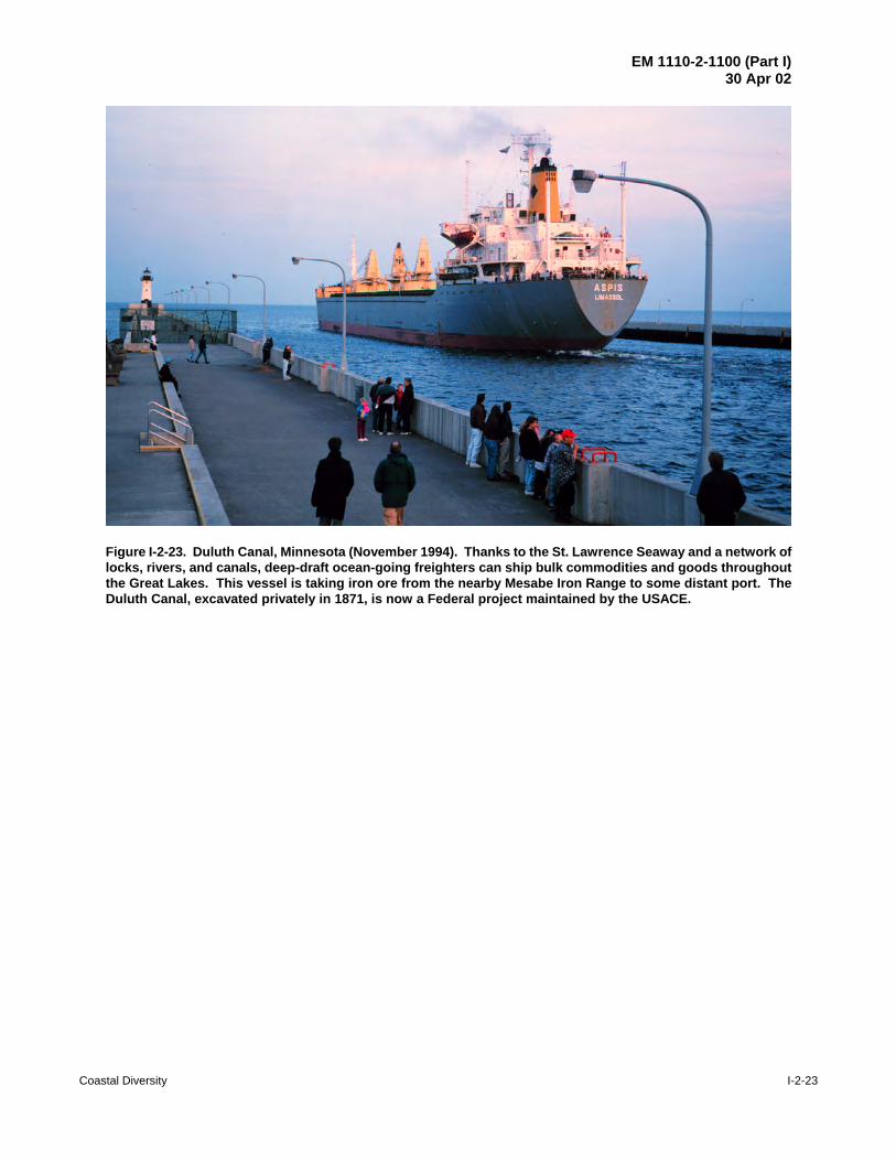
Figure I-2-23. Duluth Canal, Minnesota (November 1994). Thanks to the St. Lawrence Seaway and a network oflocks, rivers, and canals, deep-draft ocean-going freighters can ship bulk commodities and goods throughoutthe Great Lakes. This vessel is taking iron ore from the nearby Mesabe Iron Range to some distant port. TheDuluth Canal, excavated privately in 1871, is now a Federal project maintained by the USACE.

EM 1110-2-1100 (Part I)30 Apr 02
I-2-24 Coastal Diversity
Figure I-2-24. Bluffs about 1 km north of St. Joseph Harbor, eastern Lake Michigan (November 1993). In thisarea, the sand and clay bluffs are receding at an average rate of between 0.3 and 0.4 m per year. They are highlyvulnerable to ground water seepage and, during periods of high lake level, to wave attack. Freshly-slumped clayblocks can be seen on the bluff face in the right side of the image
I-2-6. References
Berryhill, Dickinson, and Holmes 1969Berryhill, H. L., Dickinson, K. A., and Holmes, C. W. 1969. “Criteria for Recognizing Ancient BarrierCoastlines,” American Association of Petroleum Geologist Bulletin 53, pp 703-707
Campbell and Moberly 1985Campbell, J. F., and Moberly, R. 1985. “130. Hawaii,” Bird, E. C. F., and Schwartz, M. L., eds., TheWorld’s Coastline, Van Nostrand Reinhold, New York, NY., p 1011-1022.
CCEE 1994Concise Columbia Electronic Encyclopedia (CCEE). 1994. Columbia University Press, Encyclopedia.com—Results for Great Lakes.
DOA 1971Department of the Army, Corps of Engineers. 1971. Report on the National Shoreline Study, Washington,DC. 20314, August 1971, 59 p.

EM 1110-2-1100 (Part I)30 Apr 02
Coastal Diversity I-2-25
Kovacs 1983Kovacs, A. 1983. Shore ice rid-up and pile-up features, Part I: Alaska’s Beaufort sea coast, CRREL ReportCR-83-9-PT-1, U.S. Army Cold Regions Research and Engineering Laboratory,Hanover, NH.
Lenček and Bosker 1998Lenček and Bosker. 1998. The Beach: The History of Paradise on Earth. Viking New York, 310 p.
Moberly and Chamberlain 1964Moberly, R. and Chamberlain, T. 1964. “Hawaiian Beach Systems,” Hawaii Institute of Geophysics Report64-2, University of Hawaii.
Shepard and Wanless 1971Shepard, Francis P., and Wanless, Harold R. 1971. Our Changing Coastlines, McGraw-Hill, New York,NY., 579 p.
Shepard 1982Shepard, Francis P. 1982. “North America, Coastal Morphology.” Encyclopedia of Beaches and CoastalEnvironments, Encyclopedia of Earth Sciences, Volume XV, Schwartz, Maurice L. Editor, Hutchinson RossPublishing Co., 940 p, pp 593-603.

EM 1110-2-1100 (Part I)30 Apr 02
I-2-26 Coastal Diversity
I-2-7. Acknowledgments
Authors of Chapter I-2, “Coastal Diversity:”
John H. Lockhart., Jr., Headquarters, U.S. Army Corps of Engineers, Washington, DC, (retired).Andrew Morang, Ph.D., Coastal and Hydraulics Laboratory (CHL), Engineer Research and Development
Center, Vicksburg, Mississippi.
Reviewer:
Joan Pope, CHL

History of Coastal Engineering I-3-i
Chapter 3 EM 1110-2-1100HISTORY OF COASTAL ENGINEERING (Part I)
30 April 2002
Table of Contents
PageI-3-1. Ancient World . . . . . . . . . . . . . . . . . . . . . . . . . . . . . . . . . . . . . . . . . . . . . . . . . . . . . . . . . . . . I-3-1
I-3-2. Pre-Roman Times . . . . . . . . . . . . . . . . . . . . . . . . . . . . . . . . . . . . . . . . . . . . . . . . . . . . . . . . I-3-1
I-3-3. Roman Times . . . . . . . . . . . . . . . . . . . . . . . . . . . . . . . . . . . . . . . . . . . . . . . . . . . . . . . . . . . . I-3-3
I-3-4. Modern Age . . . . . . . . . . . . . . . . . . . . . . . . . . . . . . . . . . . . . . . . . . . . . . . . . . . . . . . . . . . . . . I-3-4
I-3-5. Civil Engineer Era . . . . . . . . . . . . . . . . . . . . . . . . . . . . . . . . . . . . . . . . . . . . . . . . . . . . . . . . I-3-5
I-3-6. United States Army Corps of Engineers . . . . . . . . . . . . . . . . . . . . . . . . . . . . . . . . . . . . I-3-6
I-3-7. Coastal Engineering in the United States . . . . . . . . . . . . . . . . . . . . . . . . . . . . . . . . . . I-3-10
a. Nineteenth century projects . . . . . . . . . . . . . . . . . . . . . . . . . . . . . . . . . . . . . . . . . . . . . . . . I-3-10b. Nineteenth century coastal engineering . . . . . . . . . . . . . . . . . . . . . . . . . . . . . . . . . . . . . . I-3-11c. Early coastal development and shore protection . . . . . . . . . . . . . . . . . . . . . . . . . . . . . . . . I-3-12d. Early 20th century beach development and the Engineering Advisory Board on Coastal Erosion . . . . . . . . . . . . . . . . . . . . . . . . . . . . . . . . . . . . . . . . . . . . . . . . . . . . . . . . . I-3-13e. American Shore and Beach Preservation Association . . . . . . . . . . . . . . . . . . . . . . . . . . . I-3-13f. The Board on Sand Movement and Beach Erosion . . . . . . . . . . . . . . . . . . . . . . . . . . . . . . I-3-15g. The Beach Erosion Board . . . . . . . . . . . . . . . . . . . . . . . . . . . . . . . . . . . . . . . . . . . . . . . . . I-3-15h. BEB focus on basic research . . . . . . . . . . . . . . . . . . . . . . . . . . . . . . . . . . . . . . . . . . . . . . . I-3-16i. Dalecarlia reservation and World War II . . . . . . . . . . . . . . . . . . . . . . . . . . . . . . . . . . . . . I-3-19j. BEB accomplishments . . . . . . . . . . . . . . . . . . . . . . . . . . . . . . . . . . . . . . . . . . . . . . . . . . . . I-3-20k. Evolution of shore protection and the shift from structures to beach nourishment . . . . . . I-3-21l. The Coastal Engineering Research Center and the Coastal Engineering Research Board . . . . . . . . . . . . . . . . . . . . . . . . . . . . . . . . . . . . . . . . . . . . . . . . . . . . . . . . . . . . . . . . . I-3-22
(1) Early years . . . . . . . . . . . . . . . . . . . . . . . . . . . . . . . . . . . . . . . . . . . . . . . . . . . . . . . . . . . I-3-22(2) Fort Belvoir . . . . . . . . . . . . . . . . . . . . . . . . . . . . . . . . . . . . . . . . . . . . . . . . . . . . . . . . . . I-3-22(3) Field Research Facility . . . . . . . . . . . . . . . . . . . . . . . . . . . . . . . . . . . . . . . . . . . . . . . . . I-3-23(4) Shore Protection Manual . . . . . . . . . . . . . . . . . . . . . . . . . . . . . . . . . . . . . . . . . . . . . . . . I-3-23(5) Waterways Experiment Station . . . . . . . . . . . . . . . . . . . . . . . . . . . . . . . . . . . . . . . . . . . I-3-23(6) The Coastal and Hydraulics Laboratory . . . . . . . . . . . . . . . . . . . . . . . . . . . . . . . . . . . . I-3-23
I-3-8. Coastal Engineering in the Military . . . . . . . . . . . . . . . . . . . . . . . . . . . . . . . . . . . . . . . . I-3-23
a. Amphibious operations . . . . . . . . . . . . . . . . . . . . . . . . . . . . . . . . . . . . . . . . . . . . . . . . . . . I-3-23b. Expedient harbors . . . . . . . . . . . . . . . . . . . . . . . . . . . . . . . . . . . . . . . . . . . . . . . . . . . . . . . I-3-24c. Military coastal engineering studies . . . . . . . . . . . . . . . . . . . . . . . . . . . . . . . . . . . . . . . . . I-3-24d. Port operations, Republic of Korea . . . . . . . . . . . . . . . . . . . . . . . . . . . . . . . . . . . . . . . . . . I-3-25e. Port operations, Republic of Vietnam . . . . . . . . . . . . . . . . . . . . . . . . . . . . . . . . . . . . . . . . I-3-25

EM 1110-2-1100 (Part I)30 Apr 02
I-3-ii History of Coastal Engineering
(1) Vung Ro . . . . . . . . . . . . . . . . . . . . . . . . . . . . . . . . . . . . . . . . . . . . . . . . . . . . . . . . . . . . . I-3-26(2) Da Rang River . . . . . . . . . . . . . . . . . . . . . . . . . . . . . . . . . . . . . . . . . . . . . . . . . . . . . . . . I-3-26
f. Temporary wharfs . . . . . . . . . . . . . . . . . . . . . . . . . . . . . . . . . . . . . . . . . . . . . . . . . . . . . . . I-3-26g. Rapidly Installed Breakwater System . . . . . . . . . . . . . . . . . . . . . . . . . . . . . . . . . . . . . . . . I-3-27
I-3-9. Summary . . . . . . . . . . . . . . . . . . . . . . . . . . . . . . . . . . . . . . . . . . . . . . . . . . . . . . . . . . . . . . . I-3-28
I-3-10. References . . . . . . . . . . . . . . . . . . . . . . . . . . . . . . . . . . . . . . . . . . . . . . . . . . . . . . . . . . . . I-3-29
I-3-11. Acknowledgments . . . . . . . . . . . . . . . . . . . . . . . . . . . . . . . . . . . . . . . . . . . . . . . . . . . . . . I-3-36

EM 1110-2-1100 (Part I)30 Apr 02
History of Coastal Engineering I-3-iii
List of Figures
Page
Figure I-3-1. Fiscal year 1997 dredging by the U.S. Army Corps of Engineers at coastal projects . . . . . . . . . . . . . . . . . . . . . . . . . . . . . . . . . . . . . . . . . . . . . . . . . . . . . . . . . I-3-9
Figure I-3-2. Federally maintained deep-draft and small boat harbors with structures . . . . . . . I-3-9
Figure I-3-3. Federal shore protection and beach erosion control projects . . . . . . . . . . . . . . . I-3-10
Figure I-3-4. Converging jetty system designed by James B. Eads . . . . . . . . . . . . . . . . . . . . . I-3-12
Figure I-3-5. Wood crib design of Great Lakes breakwaters . . . . . . . . . . . . . . . . . . . . . . . . . . I-3-14
Figure I-3-6. Construction of Fire Island jetty, 1940 . . . . . . . . . . . . . . . . . . . . . . . . . . . . . . . . I-3-15
Figure I-3-7. Jetty construction, Rockaway Inlet, New York, 1932 . . . . . . . . . . . . . . . . . . . . I-3-16
Figure I-3-8. Hurricane storm damage, Atlantic City, NJ, 1944 . . . . . . . . . . . . . . . . . . . . . . . I-3-17
Figure I-3-9. Construction of Manasquan Inlet jetties . . . . . . . . . . . . . . . . . . . . . . . . . . . . . . . I-3-18
Figure I-3-10. Coney Island in 1941, on the eve of World War II . . . . . . . . . . . . . . . . . . . . . . . I-3-19
Figure I-3-11. Jones Island State Park on July 4th holiday . . . . . . . . . . . . . . . . . . . . . . . . . . . . . I-3-20
Figure I-3-12. Grass planting, beach restoration, 1930s . . . . . . . . . . . . . . . . . . . . . . . . . . . . . . I-3-21
Figure I-3-13. The shift from fixed structures to beach restoration and nourishment . . . . . . . . I-3-22
Figure I-3-14. Aerial photograph of the Mulberry “B” Harbor at Arromanches, France, June 1944 . . . . . . . . . . . . . . . . . . . . . . . . . . . . . . . . . . . . . . . . . . . . . . . . . . . . . . I-3-25
Figure I-3-15. Operation MIKI, Waianae, Oahu, HI, October 1949 . . . . . . . . . . . . . . . . . . . . . I-3-26

EM 1110-2-1100 (Part I)30 Apr 02
History of Coastal Engineering I-3-1
Chapter 1-3History of Coastal Engineering
I-3-1. Ancient World
The history of coastal engineering reaches back to the ancient world bordering the Mediterranean Sea, theRed Sea, and the Persian Gulf. Coastal engineering, as it relates to harbors, starts with the development ofmaritime traffic, perhaps before 3500 B.C. Shipping was fundamental to culture and the growth ofcivilization, and the expansion of navigation and communication in turn drove the practice of coastalengineering. The availability of a large slave labor force during this era meant that docks, breakwaters, andother harbor works were built by hand and often in a grand scale similar to their monumental contemporaries,pyramids, temples, and palaces. Some of the harbor works are still visible today, while others have recentlybeen explored by archaeologists. Most of the grander ancient harbor works disappeared following the fallof the Roman Empire. Earthquakes have buried some of the works, others have been submerged bysubsidence, landlocked by silting, or lost through lack of maintenance. Recently, archaeologists, usingmodern survey techniques, excavations, and old documents, have revealed some of the sophisticatedengineering in these old harbors. Technically interesting features have shown up and are now reappearingin modern port designs. Common to most ancient ports was a well-planned and effectively located seawallor breakwater for protection and a quay or mole for loading vessels, features frequently included in modernports (Quinn 1972).
Most ancient coastal efforts were directed to port structures, with the exception of a few places where lifedepended on coastline protection. Venice and its lagoon is one such case. Here, sea defenses (hydraulic andmilitary) were necessary for the survival of the narrow coastal strips, and impressive shore protection worksbuilt by the Venetians are still admired. Very few written reports on the ancient design and construction ofcoastal structures have survived. A classic treatise by Vitruvius (27 B.C.) relating the Roman engineeringexperience, has survived (Pollio, Rowland, and Howe 1999). Greek and Latin literature by Herodotus,Josephs, Suetonius, Pliny, Appian, Polibus, Strabo, and others provide limited descriptions of the ancientcoastal works. They show the ancients’ ability to understand and handle various complex physicalphenomena with limited empirical data and simple computational tools. They understood such phenomenaas the Mediterranean currents and wind patterns and the wind-wave cause-effect link. The Romans arecredited with first introducing wind roses (Franco 1996).
I-3-2. Pre-Roman Times
Most early harbors were natural anchorages in favorable geographical conditions such as sheltered baysbehind capes or peninsulas, behind coastal islands, at river mouths, inside lagoons, or in deep coves. Shortbreakwaters were eventually added to supplement the natural protection. The harbors, used for refuge,unloading of goods, and access to fresh water, were closely spaced to accommodate the safe day-to-daytransfer of the shallow draft wooden vessels which sailed coastwise at speeds of only 3-5 knots.
Ancient ports can be divided into three groups according to their structural patterns and the development ofengineering skill (Frost 1963).
a. The earliest were rock cut, in that natural features like offshore reefs were adapted to give shelter tocraft riding at anchor.
EM 1110-2-1100 (Part I)30 Apr 02
I-3-2 History of Coastal Engineering
b. In the second group, vertical walls were built on convenient shallows to serve as breakwaters andmoles. Harbors of this type were in protected bays, and often the walls connected with the defensesof a walled town (for example, ancient Tyre on the Lebanese coast). Often these basins werecloseable to traffic using chains to prevent the entry of enemy ships (Franco 1996).
c. The third group were harbors that were imposed on even unpromising coasts by use of Romaninnovations such as the arch and improved hydraulic cement. Projects like this required theengineering, construction, and financing resources of a major empire.
All ancient ports had one thing in common: they had to be kept clear of silt at a time when mechanicaldredging was unknown. This was accomplished by various means. One was by designing the outer parts ofthe harbor so that they deflected silt-bearing currents. The second was by allowing a controlled current toflow through the port or by flushing it out when necessary by means of channels. For example, at Sidon, aseries of tanks (like swimming pools) were cut into the harbor side of a natural rock reef. The tanks filledwith clear water that was held in place with sluice gates. When the gates were opened, currents of clear waterwould flush the inner harbor. Documentary and archaeological evidence show that both Tyre and Sidon wereflourishing and powerful ports from the Bronze Age through the Roman era and must therefore have beenkept clear of silt for over a thousand years (Frost 1963). Another method of preventing silt consisted ofdiverting rivers through canals so that during part or much of the year, the flow would enter the sea at locationwell away from the harbor.
The origins of breakwaters are unknown. The ancient Egyptians built boat basins with breakwaters on theNile River at Zoser's (Djoser) step pyramid (ca. 2500 B.C.) (Inman 2001). The Minoans constructed abreakwater at Nirou Khani on Crete long before the explosion of Santorini (Thera) in ca. 1500 B.C. Thebreakwater was small and constructed of material taken from nearby dune rock quarries (Inman 1974,Figure 4). In the Mediterranean, size and sophistication of breakwaters increased over time as the Egyptian,Phoenician, Greco-Macedonian, and Roman civilizations developed and evolved. Breakwaters were builtin China but generally at a later date than in the Mediterranean.
Probably the most sophisticated man-made harbor of this era was the first harbor of Alexandria, Egypt, builtwest of Pharos Island about 1800 B.C. by the Minoans. The main basin, built to accommodate 400 shipsabout 35 m in length, was 2,300 m long, 300 m wide and 6-10 m deep. Large stone blocks were used in themany breakwaters and docks in the harbor. Alexander the Great and his Greek successors rebuilt the harbor(300-100 B.C.) in monumental scale. The Island of Pharos was joined to the mainland by a 1.5 kmbreakwater with two openings dividing two basins with an area of 368 hectares (910 acres) and 15 km of quayfront. Alexandria is probably best known for the 130m-high lighthouse tower used to guide ships on afeatureless coast to the port from 50 km at sea. The multi-storied building was built with solid blocks of stonecemented together with melted lead and lined with white stone slabs. Considered one of the Wonders of theAncient World, it eventually collapsed due to earthquakes between 1326 and 1349 (Franco 1996, Empereur1997).
Another feature of the Greek harbors was the use of colossal statues to mark the entrances. Colossal statuesof King Ptolemy, which stood at the base of the lighthouse, have been found with the lighthouse debris.Historians report the most famous harbor statue was the 30 m high Colossus of Rhodes, which stood on thebreakwater heads. Three ancient windmill towers are still surviving upon the Rhodes breakwater (Franco1996). Frost (1963) notes that the Greeks had used hydraulic cement long before the Romans.

EM 1110-2-1100 (Part I)30 Apr 02
History of Coastal Engineering I-3-3
I-3-3. Roman Times
The Romans introduced many revolutionary innovations in harbor design. They learned to build wallsunderwater and constructed solid breakwaters to protect exposed harbors. They used metal joints and clampsto fasten neighboring blocks together and are often credited with discovering hydraulic cement made withpozzolanic ash obtained from the volcanic region near Naples, which hardens underwater. Frost (1963) notesthat the Greeks had used hydraulic cement long before the Romans. The Romans replaced many of the Greekrubble mound breakwaters with vertical and composite concrete walls. These monolithic coastal structurescould be built rapidly and required little maintenance. In some cases wave reflection may have been usedto prevent silting. In most cases, rubble or large stone slabs were placed in front of the walls to protectagainst toe scour. The Romans developed cranes and pile drivers and used them extensively in theirconstruction. This technology also led them to develop dredges. Another advanced technique used for deep-water applications was the watertight floating cellular caisson, precursor of the modern day monolithicbreakwater. They also used low, water-surface breakwaters to trip the waves before they reached the mainbreakwater. The peculiar feature of the vertical wall breakwater at Thapsus (Rass Dimas, Tunisia) was thepresence of vents through the wall to reduce wave impact forces. This idea is used today in the constructionof perforated caisson breakwaters (Franco 1996).
Using some of these techniques, the Romans built sophisticated breakwaters at Aquileia, Italy (ca. 180 B.C.),and at Caesarea, Israel (ca. 20 B.C.). The southwestern breakwater at Caesarea contained a “forebreakwater”that acted as a submerged reef that “trips” the wave causing it to break and dissipate energy beforeencountering the main breakwater (Inman 2001).
The largest manmade harbor complex was the imperial port of Rome; the maritime town at the mouth of theTiber River was named Portus (The Port). It is now some four km from the sea, partly buried under Rome-Fiumicino airport. Despite its importance to the capital of the empire, (300,000 tons/year of wheat fromEgypt and France), the harbor always suffered siltation from the river. Trajan, who also built the ports ofTerracina and Centumcellae, built Portus’ inner hexagonal basin. The port of Centumcellae was built justto serve his villa at a site with favorable rocky morphology. A grandiose engineering project between 107-106 B.C. created a sheltered bathing and boating retreat. Slaves from all parts of the empire excavated aharbor and hauled in massive stones to create an artificial harbor to dampen the force of the waves. After thedecline of Portus, it became, and remains, the Port of Rome. After remaining unchanged for over 1,000 years,the inner Roman Basin, which was dredged from rock (200,000 m3 or 260,000 yd3), is still in use. Romanengineers also constructed harbors in northern Europe along the main waterways of the Rhine and Danubeand in Lake Geneva. They became the first dredgers in the Netherlands to maintain the harbor at Velsen.Silting problems here were solved when the previously sealed solid piers were replaced with new “open”-piled jetties. In general, the Romans spread their technology throughout the western world. Their harborsbecame independent infrastructures, with their own buildings and storage sheds as opposed to the pre-Romanfortified city-enclosed harbors. They developed and properly used a variety of design concepts andconstruction techniques at different coastal cites to suit the local hydraulic and morphological conditions andavailable materials (Franco 1996).
The Romans also introduced to the world the concept of the holiday at the coast. The ingredients for beachholidays were in place: high population density coupled with a relatively high standard of living, a well-established economic and social elite, and a superb infrastructure of roads. From the end of the republic tothe middle of the second century of the empire, resorts thrived along the shores of Latium and Capania, andan unbroken string of villas extended along the coast from the seashore near Rome to the white cliffs ofTerracina. Fine roads connected these resorts to the capital, allowing both the upper crust and the masses todescend from sultry and vapor-ridden Rome to the sea. For five hundred years, the sybaritic town of Baiaereigned as the greatest fashionable beach resort of the ancient world. Seneca the Younger called Baiae a

EM 1110-2-1100 (Part I)30 Apr 02
I-3-4 History of Coastal Engineering
“vortex of luxury and a harbor of vice,” an alluring combination that Romans found irresistible (Lenček andBosker 1998).
I-3-4. Modern Age
After the fall of the Western Roman Empire, a long hiatus in coastal technology and engineering prevailedthroughout most of the European world with a few exceptions. Little is recorded on civil engineeringachievements during the Dark and Middle Ages. The threat of attack from the sea caused many coastal townsand their harbors to be abandoned. Many harbors were lost due to natural causes such as rapid silting,shoreline advance or retreat, etc. The Venice lagoon was one of the few populated coastal areas withcontinuous prosperity and development where written reports document the evolution of coastal protectionworks, ranging from the use of wicker faggots to reinforce the dunes to timber piles and stones, oftencombined in a sort of crib work. Protection from the sea was so vital to the Venetians, that laws from 1282to 1339 did not allow anyone to cut or burn trees from coastal woods, pick out mussels from the rockrevetments, let cattle upon the dikes, remove sand or vegetation from the beaches or dunes, or exportmaterials used for shore protection (Franco 1996).
In England, coastal engineering works date back to the Romans, who recognized the danger of floods and seainundation of low-lying lands. On the Medway, for example, embankments built by the Romans as seadefense remained in use until the 18th century (Palmer and Tritton Limited 1996). The low-lying lands,consisting of recently-deposited alluvial material, were exceeding fertile but were also vulnerable to floodingfrom both runoff and storm surges. In the Middle Ages, the Church became instrumental in reclaiming andprotecting many marshes, and monks reclaimed portions of the Fylde and Humber estuaries. In 1225,Henry III constituted by Charter a body of persons to deal with the question of drainage (Keay 1942).
Across the North Sea, the Friesland area of the Netherlands had a large and wealthy population in the period500 - 1000 A. D., and increasing need for agricultural land led to building of sea dikes to reclaim land thatpreviously was used for grazing (Bijker 1996). Water boards developed in response to the need for a mutualmeans to coordinate and enforce dike maintenance. These boards represent some of the earliest democraticinstitutions in the Netherlands.
Engineering and scientific skills remained alive in the east, in Byzantium, where the Eastern Roman empiresurvived for six hundred years while Western Rome decayed. Of necessity, Byzantium had become a seapower, sending forth fleets of merchant ships and multi-oared dromonds (swift war vessels) throughout theBlack Sea and Mediterranean. When the weary soldiers of the first crusades reached Byzantium’s capital city,Constantinople, in 1097, they were amazed and awed by its magnificence, sophistication, and scientificachievements. Constantinople was built on the hills overlooking the Golden Horn, a natural bay extendingnorth of the Bosporus. Marble docks lined the waterfront, over which passed the spices, furs, timber, grain,and the treasures of an empire. A great chain could be pulled across the mouth of the Golden Horn to preventintrusion by enemy fleets. A series of watch towers extended along the length of the Sea of Marmara, theBosphoros, and the south shore of the Black Sea, and the approach of an enemy fleet could be signaled to theemperor within hours by an ingenious code using mirrors by day and signal fires by night (Lamb 1930).
The Renaissance era (about XV - XVI centuries) was a period of scientific and technologic reawakening,including the field of coastal engineering. While the standards for design and construction remained thosedeveloped primarily by the Romans, a great leap in technology was achieved through the development ofmechanical equipment and the birth of the hydraulic sciences including maritime hydraulics (Franco 1996).“The Italian School of Hydraulics was the first to be formed and the only one to exist before the middle ofthe 17th century” (Rouse and Ince 1963). Leonardo da Vinci (1465-1519), with his well-known experimentalmethod, based on the systematic observation of natural phenomenon supported by intellectual reasoning and

EM 1110-2-1100 (Part I)30 Apr 02
History of Coastal Engineering I-3-5
a creative intuition, could be considered the precursor of hydrodynamics, offering ideas and solutions oftenmore than three centuries ahead of their common acceptance. Some of his descriptions of water movementare qualitative, but often so correct, that some of his drawings could be usefully included in a modern coastalhydrodynamics text. The quantitative definition and mathematical formulation of the results were far beyondthe scientific capabilities of the era. Even so, da Vinci was probably the first to describe and test severalexperimental techniques now employed in most modern hydraulic laboratories. To visualize the flow field,he used suspended particles and dyes, glass-walled tanks, and movable bed models, both in water and in air.The movement from kinematics to dynamics proved impossible until the correct theory of gravitation wasdeveloped, some two centuries latter by Sir Issac Newton (Fasso 1987). The variety of hydro kinematicsproblems dealt with in da Vinci’s notebooks is so vast that it is not possible to enumerate them all in this briefreview. In the 36 folios (sheets) of the Codex Leicester (1510), he describes most phenomena related tomaritime hydraulics. Richter (1970) provides an English translation of da Vinci’s notebooks (Franco 1996).The scientific ideas of the Italian Renaissance soon moved beyond the confines of that country, to theEuropean countries north of the Alps.
I-3-5. Military and Civil Engineer Era
After the Renaissance, although great strides were made in the general scientific arena, little improvementwas made beyond the Roman approach to harbor construction. Ships became more sea-worthy and globalnavigation became more common. With global navigation came the European discovery of the Americas,Australia, New Zealand, Indonesia, and other areas of the world, soon followed by migration andcolonization. Trade developed with previously unreachable countries and new colonies. France developedas the leader in scientific knowledge. The French “G’enie” officers, who, along with their military task, werealso entrusted with civilian public works, are reportedly the direct ancestors of modern civil engineers.S’ebastien le Prestre de Vauban (1633-1707) was a builder of numerous fortresses and perfected the systemof polygonal and star shaped fortifications. His most eminent public works project was the conversion ofDunkirk into an impregnable coastal fortress. Apart from the construction of several forts, there wereextensive harbor and coastal works, including the excavation of canals and harbor basins, the constructionof two long jetties flanking the entrance channel, and the erection of storehouses and workshops. A greatlock, a masterpiece of civil engineering, was built at the entrance to the Inner Harbor. Vauban himselfdesigned and supervised the lock construction. Unfortunately, no more than 30 years after its completion,the fortress was destroyed as a consequence of the Spanish War of Succession. Vauban’s projects providea good example of engineering methods and lucidity. They consisted of an explanatory memorandum, severaldrawings, and a covering letter. The memorandum had four sections: (1) general background of the scheme;(2) detailed descriptions of the different parts, with references to the drawings; (3) cost estimates; (4)features and advantages of the work. It was during this time that the term “Ingenieur” was first used inFrance, as a professional title for a scientifically-trained technician in public service.
While France enjoyed a leading position in Europe with regard to exact sciences and their applications totechnical problems, a social and economic revolution later known as the “Industrial Revolution” was takingplace in England. The riding-horse and the packhorse gave way to the coach, the wagon and the barge. Hardroads and canals replaced the centuries old soft roads and trails, dusty in dry weather and mud-bound duringrains (Straub 1964). Steam power allowed industry to be concentrated in factories that required continuoussupply of raw materials and export of manufactured goods.
In the 18th and 19th centuries, advances in navigation and mathematics, the advent of the steam engine, thesearch for new lands and trade routes, the expansion of the British Empire through her colonies, and otherinfluences, all contributed to the revitalization of sea trade and a renewed interest in port works. As thevolume of shipping grew, more vessels were needed and as the dimensions of the new vessels became larger,

EM 1110-2-1100 (Part I)30 Apr 02
I-3-6 History of Coastal Engineering
increased port facilities were necessary. Ports of the world experienced growing pains for the first time sincethe Roman era, and, except for the interruption caused by two world wars, port needs continue to grow(Quinn 1972).
I-3-6. United States Army Corps of Engineers
Since the formation of the United States, Army engineers and the Corps of Engineers have been responsiblefor or intimately associated with a wide variety of civil projects and improvements to waterways, ports, andnavigation systems. The following paragraphs summarize the history of the U.S. Army Corps of Engineers(USACE) and outline some of the Corps’ early efforts in coastal and navigation improvements.
The origins of the USACE date to June of 1775, at the beginning of the American War of Independence,when the Second Continental Congress authorized General Washington to assign a “chief engineer” for the“grand army” (Parkman 1978). General Washington selected Colonel Richard Gridley, a seasonedartilleryman, who had been preparing a line of fortifications around Boston during the early weeks of the war.Military operations during the war underscored the need for an efficient body of engineers, and in March of1779, the Continental Congress finally authorized a separate and distinct “corps of engineers,” to becommanded by Louis LeBègue Du Portail, an officer recruited by the American mission in France. The corpswas a vital unit of the Continental Army until disbanded in November 1783 with the arrival of peace. When war between France and England broke out in the 1790s Congress authorized President Washingtonto begin construction of a system of fortifications along the coast. In 1802, in anticipation of the Europeanbelligerents signing a treaty of peace, Congress cut back and reorganized the army and created a separatecorps of engineers, limited at that time to sixteen officers (Parkman 1978). The Act of March 16, 1802 hadother far-reaching consequences, as it provided further that the Corps was to constitute the personnel of amilitary academy at West Point. Congress had recognized the almost complete absence of trained militaryand civil engineers in the United States, and, in effect, established a national college of engineering. WestPoint was the only school in the country to graduate engineers until 1824, when Rensselaer PolytechnicInstitute was formed. Quickly becoming the growing nation’s primary source of engineering expertise, theCorps first concentrated on constructing and maintaining strategically-placed coastal fortifications to repelnaval attacks. But soon it became concerned with civil functions as it planned and executed the nationalinternal improvement program initiated in the 1820s (Maass 1951).
Until the early 1800s, little maintenance or improvement was done to harbors or rivers, and maintainingnavigability of waterways was considered the responsibility of the states or private interests. What little theFederal government had done was carried out by the Treasury Department, which had assisted navigation byerecting lighthouses, beacons, buoys, and public piers. In 1818, John C. Calhoun, then Secretary of War,recommended that the Corps of Engineers be directed to improve waterways navigation and othertransportation systems because these civil works would facilitate the movement of the Army and its materialswhile contributing to national economic development (USACE 1978). Congress accepted Calhoun’srecommendations and passed the landmark General Survey Act, which President James Monroe signed intolaw on April 30, 1824. It directed the President to use Army engineers to survey roads and canals. By themid-1820s Corps of Engineers officers were busy surveying the Ohio and lower Mississippi Rivers and theGreat Lakes, identifying navigation impediments, and proposing improvements and new routes.
Only a month later, on May 24, 1824, President Monroe signed the first Rivers and Harbors Act, whichauthorized the President to appropriate Federal monies to improve navigation on the Ohio and MississippiRivers. By 1829, Army engineers were using steam-powered snagboats to remove snags and floating treesand to dig out sandbars that impeded river traffic. Subsequent acts authorized a wide variety of internalimprovements and assigned Army engineers to direct and manage these projects. Work soon began on anumber of challenging locations that were deemed critical for the growth of a growing nation.

EM 1110-2-1100 (Part I)30 Apr 02
History of Coastal Engineering I-3-7
Hazardous navigation conditions on the Great Lakes also called for the rapid improvement of harbors. Withthe passage of the Rivers and Harbors Act, Congress voted a $20,000 appropriation for deepening the channelat the harbor of Presque Isle (at Erie, Pennsylvania) on Lake Erie (Drescher 1982). Signaling the beginningof federal involvement in the development of harbors on the Great Lakes, the USACE now maintains over600 navigation projects throughout these waterways.
One of the USACE’s first civil projects on an ocean coast was repairing Long Beach at Plymouth,Massachusetts. The beach was a long, narrow sand spit that formed the town’s harbor. Constantlyendangered by waves and wind, it had been a subject of concern to the citizens of the town as early as 1702,when they made it a crime to fell its trees or fire the grass. The congressional appropriation of $20,000 onMay 26, 1824, “to repair Plymouth Beach in the state of Massachusetts, and thereby prevent the harbour atthat place from being destroyed” initiated the Corps’ civil works mission in New England. Corps officerssupervised local agents, who built a cribwork breakwater along the beach’s outer shore and erected brushfences and planted grass to stabilize the sand. Similar projects were undertaken at nearby Duxbury and otherbeaches in New England (Parkman 1978). The pattern whereby Corps specialists supervise local contractorshas continued to this day for most civil works projects.
Over the succeeding century and a half, the USACE’s role in civil works grew dramatically, in step with thegrowth of the nation’s population and economy. To adequately cover this interesting story in the CEM wouldrisk doubling its size, so readers are referred to a series of books that document the history of each district(Table I-3-1).
Presently, USACE officers and a large contingent of non-military government employees maintain anavigation system of more than 40,000 km (25,000 miles) and 219 locks and dams connecting large regionsof the country. Of the nation’s top 50 ports active in foreign waterborne commerce, over 90 percent requireregular dredging (Waterborne Commerce Statistics Center 1999). Over 300 million cubic meters of dredgedmaterial are removed from navigation channels each year. In 1997, the USACE contracted for the dredgingof about half this total (157 million m3, see Figure I-3-1) at coastal sites only. This does not include inlandwaterways (Hillyer 1996).
Most inlets and harbors used for commercial navigation in the United States are protected and stabilized byhard structures. The USACE built most of the structures and is responsible for maintaining even a largernumber since the Federal Government assumed responsibility for some state and local projects. Figure I-3-2summarizes the locations of the Federal projects (Hillyer 1996).
Many U.S. coastal urban and recreational centers are protected by erosion control and storm damagereduction projects constructed cooperatively by the USACE, state, and local governments (Figure I-3-3).Although most of the 83 Congressionally authorized shore protection projects are in densely developed areas,some were constructed primarily for recreation and are associated with public or park beaches (Sudar et al.1995).

EM 1110-2-1100 (Part I)30 Apr 02
I-3-8 History of Coastal Engineering
Table I-3-1Selected Bibliography of USACE History
Region Reference
General history of USACE USACE 1998
Alaska District Jacobs 1976
Atchafalaya Basin Reuss 1998
Baltimore District Kanarek 1978
Buffalo District Drescher 1982
Charleston District Moore 1981
Chicago District Larson 1979
Detroit District Larson 1981
Galveston District Alperin 1977
Honolulu District van Hoften 1970
Jacksonville District Buker 1981
Little Rock District Rathbun 1990
Los Angeles District Turhollow 1975
Mobile District Davis 1975
New England Division Parkman 1986
New Orleans District Cowdrey 1977
New York District Klawonn 1977
North Atlantic Division Chambers 1980
Ohio River Division Johnson 1992
Pacific Ocean Division Thompson 1981
Philadelphia District Snyder and Guss 1974
Pittsburgh District Johnson 1979
Portland District Willingham 1983
San Francisco District Hagwood 1982
Savannah District Barber 1989
Seattle District Seattle District 1969
St. Paul District Merritt 1979
St. Lawrence Seaway Becker 1984
St. Louis District Dobney 1978
Wilmington District Hartzer 1984

EM 1110-2-1100 (Part I)30 Apr 02
History of Coastal Engineering I-3-9
Figure I-3-1. Fiscal year 1997 dredging by the U.S. Army Corps of Engineers at coastal projects (million m3 ). These totals do not include dredging of inland waterways and rivers, but do include Great Lakes ports (fromHillyer 1996)
Figure I-3-2. Federally maintained deep-draft and small boat harbors with structures (from Hillyer 1996)
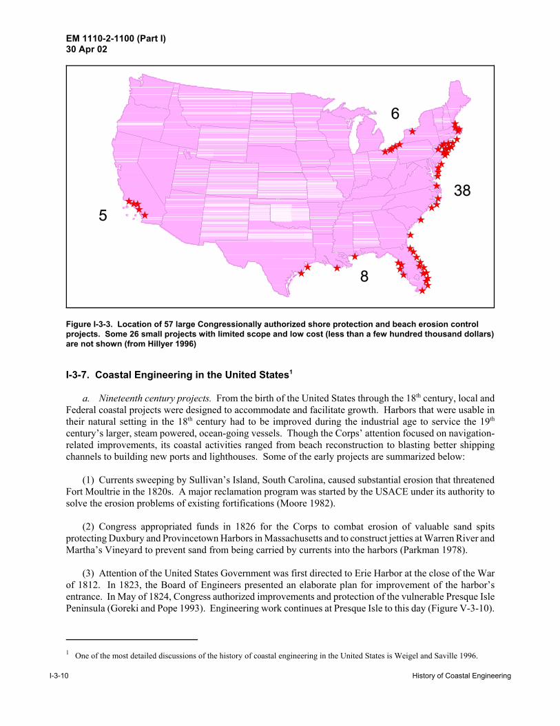
EM 1110-2-1100 (Part I)30 Apr 02
1 One of the most detailed discussions of the history of coastal engineering in the United States is Weigel and Saville 1996.
I-3-10 History of Coastal Engineering
Figure I-3-3. Location of 57 large Congressionally authorized shore protection and beach erosion controlprojects. Some 26 small projects with limited scope and low cost (less than a few hundred thousand dollars)are not shown (from Hillyer 1996)
I-3-7. Coastal Engineering in the United States1
a. Nineteenth century projects. From the birth of the United States through the 18th century, local andFederal coastal projects were designed to accommodate and facilitate growth. Harbors that were usable intheir natural setting in the 18th century had to be improved during the industrial age to service the 19th
century�s larger, steam powered, ocean-going vessels. Though the Corps� attention focused on navigation-related improvements, its coastal activities ranged from beach reconstruction to blasting better shippingchannels to building new ports and lighthouses. Some of the early projects are summarized below:
(1) Currents sweeping by Sullivan�s Island, South Carolina, caused substantial erosion that threatenedFort Moultrie in the 1820s. A major reclamation program was started by the USACE under its authority tosolve the erosion problems of existing fortifications (Moore 1982).
(2) Congress appropriated funds in 1826 for the Corps to combat erosion of valuable sand spitsprotecting Duxbury and Provincetown Harbors in Massachusetts and to construct jetties at Warren River andMartha�s Vineyard to prevent sand from being carried by currents into the harbors (Parkman 1978).
(3) Attention of the United States Government was first directed to Erie Harbor at the close of the Warof 1812. In 1823, the Board of Engineers presented an elaborate plan for improvement of the harbor�sentrance. In May of 1824, Congress authorized improvements and protection of the vulnerable Presque IslePeninsula (Goreki and Pope 1993). Engineering work continues at Presque Isle to this day (Figure V-3-10).
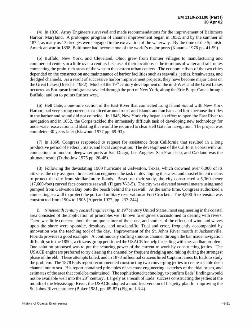
EM 1110-2-1100 (Part I)30 Apr 02
History of Coastal Engineering I-3-11
(4) In 1830, Army Engineers surveyed and made recommendations for the improvement of BaltimoreHarbor, Maryland. A prolonged program of channel improvement began in 1852, and by the summer of1872, as many as 13 dredges were engaged in the excavation of the waterway. By the time of the Spanish-American war in 1898, Baltimore had become one of the world’s major ports (Kanarek 1976 pp. 41-59).
(5) Buffalo, New York, and Cleveland, Ohio, grew from frontier villages to manufacturing andcommercial centers in a little over a century because of their locations at the terminus of water and rail routesconnecting the grain-rich areas of the west to the eastern urban centers. The economic lives of the two citiesdepended on the construction and maintenance of harbor facilities such as seawalls, jetties, breakwaters, anddredged channels. As a result of successive harbor improvement projects, they have become major cities onthe Great Lakes (Drescher 1982). Much of the 19th century development of the mid-West and the Great Lakesoccurred as European immigrants traveled through the port of New York, along the Erie Barge Canal throughBuffalo, and on to points further west.
(6) Hell Gate, a one-mile section of the East River that connected Long Island Sound with New YorkHarbor, had very strong currents that sliced around rocks and islands and ran back and forth because the tidesin the harbor and sound did not coincide. In 1845, New York city began an effort to open the East River tonavigation and in 1852, the Corps tackled the immensely difficult task of developing new technology forunderwater excavation and blasting that would be required to clear Hell Gate for navigation. The project wascompleted 30 years later (Klawonn 1977 pp. 69-93).
(7) In 1868, Congress responded to request for assistance from California that resulted in a longproductive period of Federal, State, and local cooperation. The development of the California coast with railconnections to modern, deepwater ports at San Diego, Los Angeles, San Francisco, and Oakland was theultimate result (Turhollow 1975 pp. 20-48).
(8) Following the devastating 1900 hurricane at Galveston, Texas, which drowned over 6,000 of itscitizens, the city assigned three civilian engineers the task of developing the safest and most efficient meansto protect the city from similar future floods. Based on their study, the city constructed a 5,360-meter(17,600-foot) curved face concrete seawall, (Figure V-3-5). The city was elevated several meters using sandpumped from Galveston Bay onto the beach behind the seawall. At the same time, Congress authorized aconnecting seawall to protect the port and military reservation at Fort Crockett. The 4,900-ft extension wasconstructed from 1904 to 1905 (Alperin 1977, pp. 237-244).
b. Nineteenth century coastal engineering. In 19th century United States, most engineering in the coastalarea consisted of the application of principles well known to engineers accustomed to dealing with rivers.There was little concern about the unique nature of the coast, and studies of the effects of wind and wavesupon the shore were sporadic, desultory, and unscientific. Trial and error, frequently accompanied byinnovation was the teaching tool of the day. Improvement of the St. Johns River mouth at Jacksonville,Florida provides a good example. A continuously shifting sinuous channel through the bar made navigationdifficult, so in the 1850s, a citizens group petitioned the USACE for help in dealing with the sandbar problem.One solution proposed was to put the scouring power of the current to work by constructing jetties. TheUSACE engineers preferred to try clearing the channel by frequent dredging and raking during the strongestphase of the ebb. These attempts failed, and in 1878 influential citizens hired Captain James B. Eads to studythe problem. The 1878 Eads report recommended constructing two converging jetties to create a stable deepchannel out to sea. His report contained principles of seacoast engineering, sketches of the tidal prism, andestimates of the area that could be maintained. The sophisticated technology to confirm Eads’ findings wouldnot be available well into the 20th century. Largely as a result of Eads’ success constructing the jetties at themouth of the Mississippi River, the USACE adopted a modified version of his jetty plan for improving theSt. Johns River entrance (Buker 1981, pp. 69-82) (Figure I-3-4).

EM 1110-2-1100 (Part I)30 Apr 02
I-3-12 History of Coastal Engineering
Figure I-3-4. Converging jetty system designed by James Buchanan Eads for the mouth of the St. Johns River, Florida. Figure courtesy of USAED, Jacksonville
Colonel Quincy Gillmore, familiar with Eads’ plan for Jacksonville, used a similar plan to construct the jettiesat Charleston Harbor, South Carolina, between 1878 and 1893. From the barrier islands on each side of theharbor entrance, the USACE constructed two converging jetties followed by a parallel section. The nearshore portion of the jetties was constructed to just below the low tide water surface, thereby serving as a weirand allowing the flood tide to come in normally. During the ebb tide, the bottom currents were channeledthrough the parallel section (constructed higher, with the seaward quarter above high tide) toward the bar andthis scouring action kept the new channel clear (Moore 1982). A similar plan was used at the mouth of theSt. Mary’s River at the Florida-Georgia border. Major George L. Gillespie, District Engineer in Portland,OR, submitted a plan for a dike at the mouth of the Columbia River to concentrate river currents and tidesto scour a deep channel. Construction commenced on the south jetty in 1884, a project that had to overcomefierce winter storms and hazardous working conditions (Willingham 1983).
c. Early coastal development and shore protection. From the early days of settlement to the present,Americans have built in the coastal area. During the 1600 and 1700s, the original colonies owed theirprosperity largely to the availability of good natural harbors, rich nearby fishing grounds, and active tradewith the Caribbean and Europe. As the giant continent was explored and settled in the 1800s, rivers and theGreat Lakes became the prime mode of moving goods and people to and from distant towns. In the 20thcentury, a new social phenomena arose that resulted in an ever-increasing interest in the coastal zone: moreand more Americans achieved the economic means and leisure time to enjoy the beach for recreationalpurposes. Even before beaches became popular vacation destinations, engineers constructed structures to aidnavigation, to halt erosion, and to protect shore front development from storm surge. They designedbulkheads, revetments, and seawalls to hold the shoreline in place. Generally, these designs were successful,with Galveston, Texas, and San Francisco, California, being two examples of early seawall construction.Other structures, such as groins and jetties, impeded longshore transport of sand. Groins are intended to

EM 1110-2-1100 (Part I)30 Apr 02
History of Coastal Engineering I-3-13
protect a finite beach section, while jetties keep sand out of the navigation channel between the jetties, defineand maintains the harbor entrance channel, and provide calm water access to the harbor facilities(Figures I-3-5, I-3-6). For jetties built along uninhabited coastal areas in the 19th and early 20th centuries, thebuildup of sand on the up-drift beach and the loss of sand on the downdrift beach was considered a minorconsequence compared to the major benefits of ocean navigation trade (Figure I-3-7). In nearly everyinstance, these harbor structures interrupted the alongshore movement of sand and starved nearby downdriftbeaches (USACE 1971), but it was not until the shore was developed in the later 20th century that thisinterruption of sand transport was regarded as a problem.
d. Early 20th century beach development and the Engineering Advisory Board on Coastal Erosion. Asurbanization and congestion increased, the more affluent escaped to the seashore, where resorts arose toaccommodate them. Until the age of the automobile, these resorts remained small isolated coastal enclavestied to the hinterland by rails. The technical revolution brought electric trains, automobiles, gasoline-poweredpleasure boats, labor-saving devices for the home, and a new era of leisure to a prospering nation (USACE1971; Morison and Commager 1962). Electricity provided convenient power to energy-poor barriers.Changing morals allowed people to sunbathe and enjoy the hedonism of the beach experience. And with thegrowing use of the automobile, beach-goers in increasing numbers followed newly-built roads to the coast. Concern about shore erosion grew as more people acquired property and built homes and businesses,assuming a stable shoreline.
The New Jersey shore, close to the New York and Philadelphia urban areas, was one of the first highlydeveloped shorelines (Figures I-3-8 and I-3-9). During the period 1915 to 1921, three hurricanes and fourtropical storms battered the Jersey shore, causing severe beach erosion. In New Jersey, millions of dollarswere spent on uncoordinated and sometimes totally inappropriate erosion control structures which oftenproduced results that were only minimally effective, and, in some cases, counterproductive (Hillyer 1996). Engineers and city managers soon realized that individual property owners were incapable of dealing withcoastal erosion and that a broader approach was necessary. In 1922, because of rapidly eroding shorelinesand revenue losses to the coastal communities, the State funded and appointed an Engineering AdvisoryBoard on Coastal Erosion. Its only recommendation was that further research was needed (Moore and Moore1983).
In contrast to the haphazard development of the Jersey shore, some of the early large-scale coastal projectsproved to be remarkably successful social and engineering accomplishments. America’s first largeengineered beach fill was the boardwalk and recreational beach on Coney Island in 1922 - 1923 (Farley1923). With the completion of the project, immigrants and factory workers could escape the sweatshops ofthe sweltering city and enjoy a (crowded) Sunday at the beach for only a nickel subway ride (Figure I-3-10;Stanton 1999). This was followed by the ambitious construction of the Jones Beach Parkway by RobertMoses and the Long Island State Park Commission in 1926 - 1929, during which more than 30 million m3
of sand were pumped to create Jones Island (DeWan 1999; Kana 1999) (Figure I-3-11). In Chicago, theentire waterfront was reshaped between 1920 and 1940 with the addition of over 14.2 square km of fill,resulting in one of America’s premier urban parks (Chrzastowski 1999). These were city- and state-sponsoredprojects, with minimal input by the Federal Government.
e. American Shore and Beach Preservation Association. Delegates (85) representing 16 states met atAsbury Park, New Jersey, in 1926, to discuss their growing coastal zone problems. After the first meeting,two more, following shortly thereafter, led to the formation of the American Shore and Beach PreservationAssociation (ASBPA). The Association brings together a cross section of engineers, public officials, Stateand Federal personnel, and coastal property owners. Their aim is that “Man must come to the rescue of thebeaches.” Members see themselves as leaders and teachers in a conservation movement to fight shore andbeach erosion (Patton 1934). Their influence in State and Federal governments and continued interest incoastal zone issues is responsible for many of the laws and actions to protect the U. S. shores and beaches.
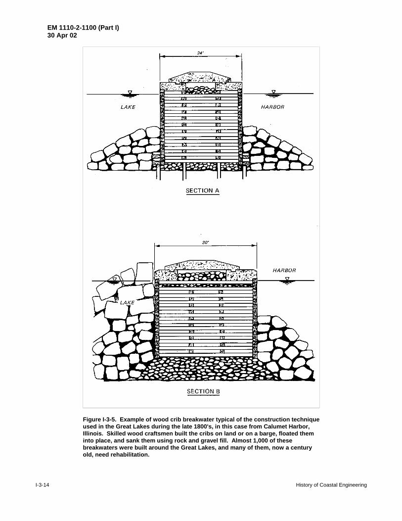
EM 1110-2-1100 (Part I)30 Apr 02
I-3-14 History of Coastal Engineering
Figure I-3-5. Example of wood crib breakwater typical of the construction techniqueused in the Great Lakes during the late 1800's, in this case from Calumet Harbor,Illinois. Skilled wood craftsmen built the cribs on land or on a barge, floated theminto place, and sank them using rock and gravel fill. Almost 1,000 of thesebreakwaters were built around the Great Lakes, and many of them, now a centuryold, need rehabilitation.

EM 1110-2-1100 (Part I)30 Apr 02
History of Coastal Engineering I-3-15
Figure I-3-6. Construction of Fire Island jetty on Democrat Point, at the west end of Fire Island, Long Island,New York. Many early USACE jetties were built from the land moving seaward using materials brought in bytrain. Photograph taken 3 Jan 1940, from Beach Erosion Board Archives.
f. The Board on Sand Movement and Beach Erosion. On January 29, 1929, Major General EdgarJadwin, Chief of Engineers, USACE, issued a Special Order creating a four-officer board “to investigate andreport on the subject of sand movement and beach erosion at such localities as may be designated by the Chiefof Engineers.” The Chief of Engineers designated Jamaica Bay, New York, and Cold Springs Inlet, NewJersey, as the first two projects for investigation by the “Sand Board” as it became familiarly known. Theboard employed two consultants, Dr. Douglas W. Johnson of Columbia University and ProfessorThorndike Saville of the University of North Carolina. With their advice and assistance, a list of fieldexperiments was prepared. The northern coast of New Jersey, with its area of active erosion and numerousshore protection installations was selected for conducting the experiments. Lieutenant Leland K. Hewitt wasassigned to the board in April 1929, to conduct the experiments. Morrough P. O’Brien, recently returnedfrom Freeman Scholarship studies in Europe, was borrowed from the University of California to provideexpert assistance in the studies. Hewitt and O’Brien set up their headquarters in Long Branch, New Jersey,and began assembling equipment and personnel to carry out their task. Thus began a USACE researchprogram destined to have far-reaching effects (Wilson and Eaton 1960)
g. The Beach Erosion Board. During this period, the ASBPA, under the leadership of J. Spencer Smith,its persuasive president, was engaged in a campaign to bring combined Federal, State and local effort to bearupon the U. S. beach preservation problems. After two years of Congressional hearings, Section 2 of theRiver and Harbor Act of 1930, authorized and directed the Chief of Engineers “to cause investigations andstudies to be made in cooperation with appropriate agencies of the various states on the Atlantic, Pacific, andGulf coasts and on the Great Lakes, and Territories, with a view of devising effective means of preventingerosion of the shores of coastal and lake waters by waves and currents . . .” The new law also provided forthe creation of the Beach Erosion Board (BEB) by the provision “that there shall be organized under theChief of Engineers, United States Army, by detail from time to time from the Corps of Engineers and fromthe engineers of state agencies charged with beach erosion and shore protection, a board of seven members,

EM 1110-2-1100 (Part I)30 Apr 02
I-3-16 History of Coastal Engineering
Figure I-3-7. Construction of the jetty on the east side of Rockaway Inlet, Long Island, New York, 12 July1932. The urban area on the opposite side of the inlet is the east end of Coney Island, and Jamaica Bay is inthe distance. In seven decades, the fillet has filled with sand to approximately the end of the jetty seen inthis image. Photograph from Beach Erosion Board Archives.
of whom four shall be officers of the Corps of Engineers and three shall be selected with regard to theirspecial fitness by the Chief of Engineers from among the state agencies cooperating with the WarDepartment. The board will furnish such technical assistance as may be directed by the Chief of Engineersin the conduct of such studies as may be undertaken and will review the reports of investigation made . . .”Obviously, reconsideration of the mission and need for the original Board on Sand Movement and BeachErosion was required. Since the new law defined the functions of the BEB as being related to cooperativestudies with the states, It was decided to create two boards, one known as the Shore Protection Board (SPB),that would conduct investigations and report upon problems concerning federal property shore protection andthe other, the BEB to have similar responsibilities with respect to cooperative studies. Members of the SPBconsisted of the military members of the BEB plus the District Engineer for the concerned locality. For thenext sixteen years the two boards shared the same staff and headquarters until the SPB was abolished and itsduties transferred to the BEB. (Wilson and Eaton 1960)
h. BEB focus on basic research (Willingham 1983). The Corps had, historically,not favored expenditure of Federal funds to protect private property, whether in river basins or coastalflood plains. During the 1930's, however, attitudes began to change, and Congress expanded Federal

EM 1110-2-1100 (Part I)30 Apr 02
History of Coastal Engineering I-3-17
Figure I-3-8. Atlantic City, New Jersey, at the mouth of Absecon Inlet, 15 September 1944. This is one of aseries of images taken after the hurricane of 14 September, a Category 3 storm that caused 390 deaths in thenortheast U.S. This photograph illustrates the degree of urban development along this coast. Photographtaken from a blimp from the U.S. Naval Air Station, Lakehurst, NJ. Official U.S. Navy Photograph (from BeachErosion Board Archives)
participation in coastal protection. A significant legislative event was the passage in 1936 of an Actwherein it was declared the policy of the United States “... to assist in the construction whereFederal interests are involved, but not the maintenance, of works for the improvement and protectionof the beaches along the shores of the United States, and to prevent erosion due to the action ofwaves, tides, and currents, with the purpose of preventing damage to property along the shores of theUnited States, and promoting and encouraging the healthful recreation of the people...” The Act furtherauthorized the Board “to publish from time to time such useful data and information concerning the protectionof beaches as the Board may deem to be of value to the people of the United States...” The act alsorequired that the Board “in making its report on any work or project relating to shore protection shall,

EM 1110-2-1100 (Part I)30 Apr 02
I-3-18 History of Coastal Engineering
Figure I-3-9. Construction of Manasquan Inlet jetties, New Jersey, October 2, 1930, view looking north. Material for the jetties was supplied via an elevated roadway that extended out to sea from the land. Notethat sand is already accumulating on the south (lower) side of the south jetty. The shoreline is continuous,and at this site the inlet was dredged after the jetties were completed. Other man-made openings that arenow Federal navigation projects include Panama City Inlet, Florida, Duluth Cut, Minnesota, and AransasPass, Texas. (Photograph from Beach Erosion Board archives)
in addition to any other matters upon which it may be required to report, state its opinion as to the advisabilityof adopting the project; what Federal interest, if any, is involved in the proposed improvement; and whatshare of the expense, if any, should be borne by the United States.” (Cited in Wilson and Eaton 1960).
Although there was substantial support in Congress for federal aid in coastal protection, much difficultywas encountered in determining the proper extent of such aid. The BEB, lacking more specific instructionsfrom Congress, interpreted “federal interest” as pertaining only to the interest of the United States as alandowner of shore property. This resulted in practically no recommendations for federal aid by the BEBduring the 1930s. Other Federal agencies were concerned with putting people to work during the depressionand interpreted the 1936 Act differently. The Works Progress Administration built revetments, dikes,retaining walls, and jetties on North Carolina’s Outer Banks at a cost more than $4 million. The Corps heldback on coastal construction projects because of uncertainties about predicting conditions at individual coastalsites revealed by board survey reports. The BEB, driven by professional curiosity, undertook

EM 1110-2-1100 (Part I)30 Apr 02
History of Coastal Engineering I-3-19
Figure I-3-10. Coney Island in 1941, on the eve of World War II. For only a 5-cent subway ride, workers fromthe sweltering city could relax at the beach (from Beach Erosion Board archives)
scientific investigations into coastal processes despite the lack of authorization in either the 1930 or 1936 acts.By the beginning of World War II, the BEB was publishing technical reports and memoranda on its researchresults (Moore and Moore 1991).
i. Dalecarlia reservation and World War II. Expansion of military activities prior to our entry intoWorld War II required the removal of the Washington Engineering District and the BEB from the NavyBuilding on Constitution Ave. in Washington, D.C. to a small office building on the Dalecarlia reservationin Washington. The new site was adequate for expansion of facilities, which was to follow, and admirablyserved the BEB’s needs. Upon our entry in the war, need soon arose for intelligence to meet amphibiousoperations requirements and research to explore means of providing expedient harbor facilities. Logically,the Chief of Engineers called on the BEB staff for assistance on these problems. In addition, the BEB wastasked to train intelligence teams to staff the various military commands. Although these activities weredirected toward military requirements, they provided much additional data and knowledge for later use in theBoard’s peacetime mission. Interest and activity in Congress to clarify the problem of federal aid for shoreprotection resumed as the war drew to a close. Public Law 166, enacted on July 31, 1945, substituted “publicinterest” for “Federal interest” as previously used in the 1936 Act, and a year later, Public Law 727 spelledout the conditions and limitations for federal aid for shore protection works. Only publicly owned shoreswere eligible and the Federal contribution could not exceed one-third of the first cost of protective works withno contribution toward maintenance cost. During the Korean War, most of the Board’s staff was againdiverted to military efforts. During this lull in preparation of cooperative studies, Technical ReportNo. 4, Shore Protection Planning and Design, was produced. The report was a manual of coastalengineering that summarized the knowledge gained by the BEB and representing its current technicaldoctrine. Cooperative studies resumed at an accelerated pace with the end of the Korean War. Congress

EM 1110-2-1100 (Part I)30 Apr 02
I-3-20 History of Coastal Engineering
Figure I-3-11. Jones Island State Park, Long Island, New York, 4 July, 1958. One of the nation’s premierurban beaches, Jones Beach is only 45 km from Manhattan, but traffic can be problematic on some days. The legend on the photograph states that there are 11,117 cars in the parking lots. From Beach ErosionBoard archives
amended the law to permit Federal aid to privately owned shores when a public benefit resulted and to permitaid toward periodic beach nourishment costs. The 1954 and 1955 River and Harbor Acts authorized sixty-two federal aid projects, a significant increase over the five projects authorized up to that date (Wilson andEaton 1960).
j. BEB accomplishments. In summary, the BEB made substantial progress toward establishing soundcoastal engineering techniques and established a research impetus in coastal processes. It commenced thecollection of a permanent record of pertinent data and provided a manual on the best techniques to addressspecific shore erosion problems. The presence of Murrough P. O’Brien and Thorndike Saville on the BeachErosion Board for such an extended period provided a continuity of objective and effort unique in publicservice (Wilson and Eaton 1960). During its 33-year existence, the BEB reviewed 149 cooperative studyreports and two Federal surveys of beach erosion problems. The BEB reviewed 114 of the cooperativestudies following the 1946 legislation allowing Federal participation in construction cost and recommended72 as Federal projects. The BEB published 135 technical memoranda and four technical reports, 130 ofwhich were published after the 1946 legislation authorizing the BEB to make general investigations andpublish technical reports (Moore and Moore 1991).

EM 1110-2-1100 (Part I)30 Apr 02
History of Coastal Engineering I-3-21
Figure I-3-12. Workers planting grass on a beach restoration project. The date and location of this imagewere not recorded, but the scene is likely the Outer Banks. Many dune and beach restoration efforts,sponsored by the National Park Service and other agencies during the late 1930s, also served as work reliefefforts for a nation trying to recover from the Great Depression. Photograph from the Beach Erosion BoardArchives
k. Evolution of shore protection and the shift from structures to beach nourishment. Prior to the 1950s,the general practice was to use hard structures to protect against beach erosion or storm damages. Thesestructures were usually coastal armoring such as seawalls and revetments or sand-trapping structures suchas groins. During the 1920s and ‘30s, private or local community interests protected many areas of the shoreusing these techniques in a rather ad hoc manner. In certain resort areas, structures had proliferated to suchan extent that the protection actually impeded the recreational use of the beaches. Erosion of the sandcontinued, but the fixed back-beach line remained, resulting in a loss of beach area. The obtrusiveness andcost of these structures led the USACE in the late 1940s and early 1950s, to move toward a new, moredynamic, method. USACE projects no longer relied solely on hard coastal defense structures as techniqueswere developed which replicated the protective characteristics of natural beach and dune systems. Theresultant use of artificial beaches and stabilized dunes as an engineering approach was an economically viableand more environmentally friendly means for dissipating wave energy and protecting coastal developments.Artificial beaches also had more aesthetic and recreational value then structured shores. The transition fromhard structures to beach fill approaches is depicted in Figure I-3-13, which compares the percentage ofFederal shore protection funds spent on beach nourishment and on coastal protection structures per decade.Since the 1970s, 90 percent of the Federal appropriation for shore protection has been for beach nourishment(Hillyer 1996).
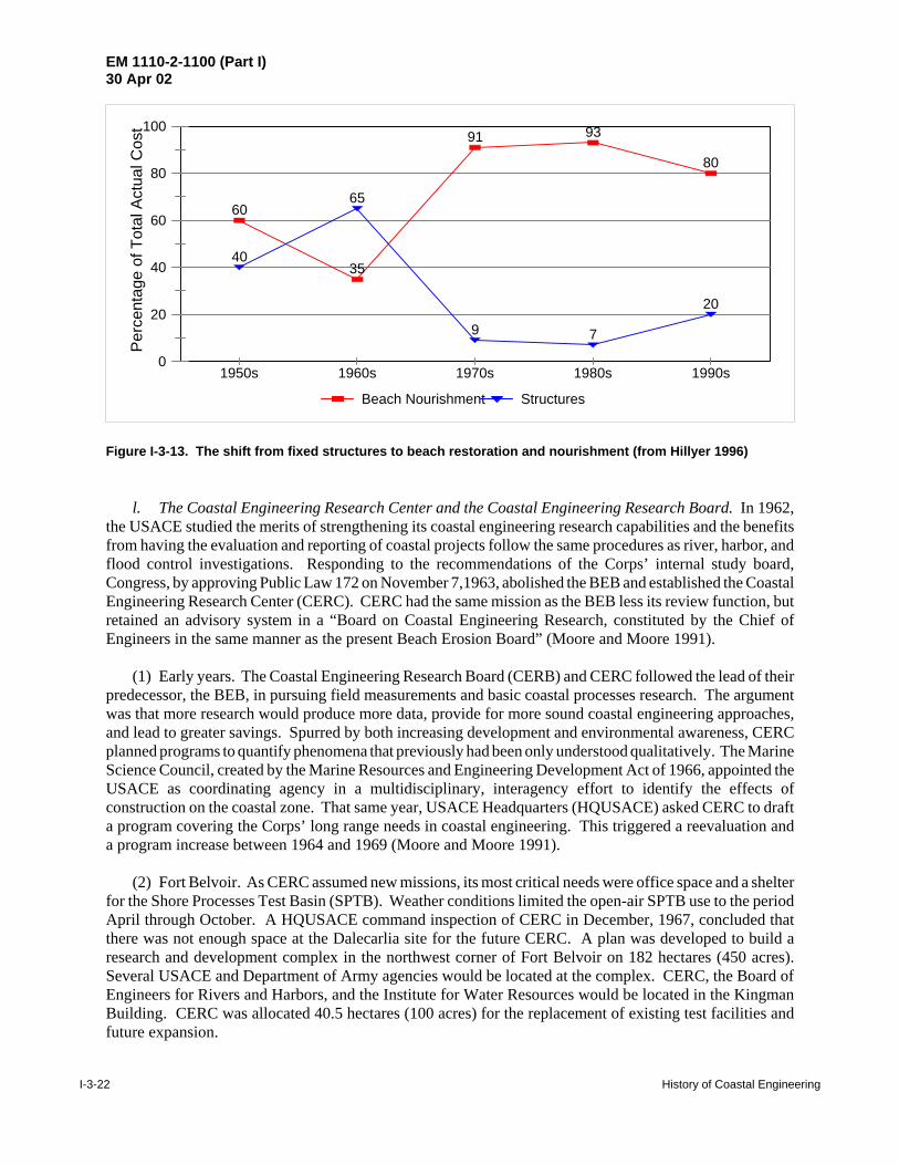
EM 1110-2-1100 (Part I)30 Apr 02
I-3-22 History of Coastal Engineering
0
20
40
60
80
100 Pe
rcen
tage
of T
otal
Act
ual C
ost
1950s 1960s 1970s 1980s 1990s
60
35
91 93
80
40
65
9 7
20
Beach Nourishment Structures
Figure I-3-13. The shift from fixed structures to beach restoration and nourishment (from Hillyer 1996)
l. The Coastal Engineering Research Center and the Coastal Engineering Research Board. In 1962,the USACE studied the merits of strengthening its coastal engineering research capabilities and the benefitsfrom having the evaluation and reporting of coastal projects follow the same procedures as river, harbor, andflood control investigations. Responding to the recommendations of the Corps’ internal study board,Congress, by approving Public Law 172 on November 7,1963, abolished the BEB and established the CoastalEngineering Research Center (CERC). CERC had the same mission as the BEB less its review function, butretained an advisory system in a “Board on Coastal Engineering Research, constituted by the Chief ofEngineers in the same manner as the present Beach Erosion Board” (Moore and Moore 1991).
(1) Early years. The Coastal Engineering Research Board (CERB) and CERC followed the lead of theirpredecessor, the BEB, in pursuing field measurements and basic coastal processes research. The argumentwas that more research would produce more data, provide for more sound coastal engineering approaches,and lead to greater savings. Spurred by both increasing development and environmental awareness, CERCplanned programs to quantify phenomena that previously had been only understood qualitatively. The MarineScience Council, created by the Marine Resources and Engineering Development Act of 1966, appointed theUSACE as coordinating agency in a multidisciplinary, interagency effort to identify the effects ofconstruction on the coastal zone. That same year, USACE Headquarters (HQUSACE) asked CERC to drafta program covering the Corps’ long range needs in coastal engineering. This triggered a reevaluation anda program increase between 1964 and 1969 (Moore and Moore 1991).
(2) Fort Belvoir. As CERC assumed new missions, its most critical needs were office space and a shelterfor the Shore Processes Test Basin (SPTB). Weather conditions limited the open-air SPTB use to the periodApril through October. A HQUSACE command inspection of CERC in December, 1967, concluded thatthere was not enough space at the Dalecarlia site for the future CERC. A plan was developed to build aresearch and development complex in the northwest corner of Fort Belvoir on 182 hectares (450 acres).Several USACE and Department of Army agencies would be located at the complex. CERC, the Board ofEngineers for Rivers and Harbors, and the Institute for Water Resources would be located in the KingmanBuilding. CERC was allocated 40.5 hectares (100 acres) for the replacement of existing test facilities andfuture expansion.

EM 1110-2-1100 (Part I)30 Apr 02
History of Coastal Engineering I-3-23
(3) Field Research Facility. Prior to its move to Fort Belvoir, CERC had planned and budgeted toconstruct a Field Research Facility (FRF) to evaluate and examine coastal phenomena on prototype (full-size)scale. CERC learned that the U.S. Navy was preparing to surplus a bombing range at Duck, North Carolina,and acquired the property in 1973. On 29 August 1980, the 50th Anniversary of the creation of the BeachErosion Board, the FRF was officially opened. The 73.7-hectare (182-acre) FRF stretches from ocean tosound, contains a 589-m (1800-foot) pier and laboratory facilities and is used for physical and biologicalstudies (Mason 1979). Meteorological, topographical and oceanographic data are continuously recorded, andthe staff conduct research projects at the site and frequently host large field experiments involving otherFederal, state and local agencies, plus U.S. and foreign universities. The FRF’s advantages of ocean location,research pier, sophisticated infrastructure, synoptic and continuing hydrodynamic and process database, andexperienced staff are unique in the United States. Data are accessible on the Internet at the FRF’s Web page:http://www.frf.usace.army.mil/frf.html
(4) Shore Protection Manual. When first established, CERC was the only Federal agency with a missionin coastal engineering and almost alone in funding studies of waves and their effects. The research programsat CERC, with their field and laboratory testing and data collection, had an immense practical value. CERC’sfirst combined volume containing guidance on coastal science and engineering was Shore Protection,Planning, and Design, Technical Report No. 4 (TR-4), first issued in 1954. The USACE District andDivision staffs had a need to apply the data and research results reported by CERC into useful design tools,and they often relied on TR-4 and some related Engineering Manuals published by HQUSACE for designguidance. The Shore Protection Manual (SPM) was first published by CERC in 1973 as the updatedreplacement for TR-4. CERC used the SPM as its primary technology transfer mechanism for many years,with a second edition printed in 1975, a third in 1977, and a fourth and final edition in 1984.
(5) Waterways Experiment Station. A number of events and policy changes in the early 1980's shiftedCERC’s emphasis into more applied research and moved the laboratory to the Waterways Experiment Station(WES) in Vicksburg, Mississippi. Despite disruptions caused by the 1983 relocation and declining researchbudgets, CERC prospered in Vicksburg. Reimbursable project work more than compensated for the decline.Mathematical modeling, sophisticated wave tanks and basins (part of the reason for the move), and a closer,more responsive relation with the USACE District and Division staffs all contributed to increased workload.
(6) The Coastal and Hydraulics Laboratory. In the early 1990s, due to political and policy changes,Federal funding for the beach erosion control and flood control projects was severely curtailed and closelyregulated. This resulted in reduced research funding and a decrease in the number of new beach erosioncontrol and flood control studies at CERC and the Hydraulics Laboratory. During 1996, both laboratorieswere combined into one new entity, the Coastal and Hydraulics Laboratory (CHL). CERC’s traditionalfunctions such as coastal engineering research, design guidance development such as this manual, and designassistance are still provided by the CHL with the advice of the CERB and a field review group of Divisionand District staff engineers.
I-3-8 Coastal Engineering in the Military
a. Amphibious operations. Amphibious military operations are not new. Herodotus (1992, translation)describes, in The Histories, how Xerxes constructed and used a floating causeway across the Hellespont (theDardanelles) in 480 B.C. The first amphibious operation in the Americas was the 49-day siege of the FrenchFortress of Louisburg on Cape Breton Island, Nova Scotia, Canada, in 1745. The Chief Engineer of theoperation was Richard Gridley who published that same year the first map in America, a “Plan of the Cityand Fortifications of Louisburg,” and who later became the first Chief Engineer under Commander-in-ChiefGeorge Washington in 1775. Many amphibious operations were conducted in North Africa, Italy, France,and the Pacific during World War (W.W.) II. These exercises taught us that for a successful over-the-beach

EM 1110-2-1100 (Part I)30 Apr 02
I-3-24 History of Coastal Engineering
assault, details and forecasts of changes must be acquired of coastal type, beach configuration,morphodynamics, profiles, wave conditions, tides, beach material, beach trafficability, and nearshore andoffshore bottom-holding capacity for moorings and anchored ships. At the start of the war, many charts wereavailable showing areas safe for deep-draft navigation and details of land topography, but hardly any of thenearshore areas where assault troops and supplies could be landed. Much of this type of information wascollected and evaluated during the war. Of prime importance to military amphibious operations are the waveconditions that can be anticipated. Correlations among wind strength, duration, fetch, and wave height andperiod were developed in the United States and in the United Kingdom (U.K.) for wave forecast for planningand for operations. The state-of-the-art in military coastal engineering at the end of W.W. II was documentedin the Manual on Amphibious Oceanography, (University of California at Berkley (UCB), Institute ofEngineering Research (IER) 1952) (Wiegel 1999).
b. Expedient harbors. Expedient harbor design for the invasion of Normandy also required substantialcoastal engineering effort. The design of the two Mulberry harbors (“A” at St. Laurent (Omaha Beach) and“B” at Arromanches) required information on wave and tide prediction (design tide range was 7.3 meters (24feet)), wave diffraction, wave induced forces, bottom conditions, and placement of structures and theirfoundations. Wave-diffraction theory (wave transmission about the tip or through a gap betweenbreakwaters) was developed for this project. The Mulberry Harbor was designed in two parts. The portionclosest to shore, in shallow water, had a breakwater of vertical reinforced-concrete caissons (code name“Phoenix”) and sunken ships protecting it, while the seaward portion was protected by moored floatingbreakwaters (“Bombardon”). The Bombardon had a cross section similar to a Maltese cross in shape; eachunit was 61 meters (200 feet) in length, 7.6 meters (25 feet) in beam and depth with 5.8 meters (19 feet) draft.They were deployed in pairs with a 15.2 meters gap between pairs. Located inside the shallow watersheltered area were pier heads and mile-long pontoon-supported flexible bridges (causeways code named“whales”). After initial construction, a storm along the Normandy coast with gale winds blowing from thenortheast generated sea conditions larger than project design waves. Operations were disrupted and delayed,with great damage to the artificial harbors, craft and ships. Mulberry “A” suffered damage beyond repair.Shown in Figure I-3-14 Is Mulberry “B” after being repaired. The Civil Engineer in War, A Symposium ofPapers on Wartime Engineering Problems, Volume 2, Docks and Harbors (Institute of Civil Engineers 1948)provides details on the design, installation, and performance of the Mulberry Harbors (Wiegel 1999).
c. Military coastal engineering studies. After W.W. II, UCB contracted with the Office of NavalResearch (ONR) to review amphibious operations reports from the war. As expected, many landing-craft andamphibious-vehicle casualties were due to enemy action, but many were related to problems with waves andcurrents causing capsizing, swamping, broaching, getting stuck on bars and, when the ramps were down,filling with water and sand. Another major problem was beach trafficability. Vehicles were frequently stuckin the sand. A trafficability study of beach sand characteristics, beach slope, water level, and vehicle typewas made. It was observed that saturated sand near the water’s edge would liquefy due to vibrationsproduced by the vehicular traffic. Several full-scale amphibious assault-training exercises were observed indetail and reports prepared on the observations and findings.
During the 25 October, 1949, exercise across three west coast beaches at the Waianae-Pokai Bay region ofOahu, Hawaii, long-period waves surging up the steep beach face caused substantial landing craft casualtieson two of the beaches. Many of the craft broached and were shoved onto the steep beach by the surgingbreakers (see Figure I-3-15). Of the 20 landing craft sent ashore in 3 “waves” in the first 15 minutes of theamphibious exercise, 7 retracted and 8 were lost, some filling with water and sand when the ramps werelowered. The exercise was quickly halted and five of the craft later salvaged. Because of the problemsexperienced moving personnel, equipment and supplies through the surf and over the beach, the Departmentof Defense began the development of helicopters and air cushion vehicles (Wiegel 1999).

EM 1110-2-1100 (Part I)30 Apr 02
History of Coastal Engineering I-3-25
Figure I-3-14. Aerial photograph of the Mulberry “B” Harbor at Arromanches, France, June 1944 (fromInstitution of Civil Engineers, London, England, 1948, p. 242)
d. Port operations, Republic of Korea. One of the major amphibious operations in the Republic ofKorea (ROK) was the invasion at Inchon Harbor. The east coast of the ROK is generally rocky sea cliffs,while the south and west coasts are extensive mud flats with many small conical islands. During low tide atInchon, the tidal flats extend at least 50 km offshore and the only approach to the port is a narrow channel1 to 2 meters deep at zero tide. Extreme tides, ranging from -0.6 meters to +9.8 meters, provided manyengineers their first experience with a sea of water quickly changing into a sea of mud. After the15 September 1950 amphibious assault, General MacArthur said “. . . conception of the Inchon landing wouldhave been impossible without the assurance of success afforded by the use of the Seabee pontoon causewaysand piers.” The tidal basin and other facilities were relatively intact at the time of the invasion. However,during the U.S. evacuation in January 1951, the lock gates to the tidal basin were demolished, then rebuiltafter return of the U.S. forces in February 1951 (Wiegel 1999).
e. Port operations, Republic of Vietnam. In Vietnam, the U.S. Navy Officer in Charge of Constructionwas responsible for Saigon-Newport and DaNang deep-water ports. Data were collected on coastalsediments, storms, tides, and waves to plan the dredging of these ports and seven other sites. The Army portconstruction section used these data and the Beach Erosion Board’s Technical Report No. 4, Shore ProtectionPlanning and Design, to prepare detailed design of port facilities. The DeLong Corporation’s installationof piers, prefabricated causeway components, and use of self elevating barges also contributed to successfulport facility operations. The sand on many of the Vietnamese beaches was of such character that over-the-shore operations were almost impossible. Rock, concrete, articulators, pierced-steel planking and other meansattempted to stabilize the sand were serviceable for very limited periods ranging from days to two weeks.Waves on the foreshore undermined the stabilizing structures and decreased the bearing capacity, resultingin the structures sinking out of sight. Engineers, drawing on their W.W. II and subsequent experience, useddraglines and blasting to dig nearby coral, crush it, and then place it in compacted layers where the foreshorehad been previously excavated for the purpose. This installation lasted several months with only minor repairand was judged very satisfactory (Wiegel 1999).
EM 1110-2-1100 (Part I)30 Apr 02
I-3-26 History of Coastal Engineering
Figure I-3-15. Operation MIKI, Waianae, Oahu, HI, October 1949, (Many landing craft broached and wereshoved onto the beach by surging breakers) (from Wiegel and Kimberly 1949)
(1) Vung Ro. For the construction of the port of Vung Ro to support the major air base at Tuy Hoa,estimates of typhoon and monsoon waves were made and wave refraction studies used to plan the port.Port development included landing-craft ramps, a floating pontoon cube barge dock, two DeLong bargepiers (183 x 24.4-meters) (600 x 80-feet) with two girder spans off a 120-meter (394-foot) rock fill causeway,tanker mooring facilities and a pipeline connecting to the tank farm south of Tuy Hoa airstrip about 15.5 km(9.6 miles) distance. Seven months after the port was completed the facilities were struck by a typhoon, butsurvived wave conditions exceeding the design wave criteria (Wiegel 1999).
(2) Da Rang River. The U.S. Air Force wanted a harbor closer to the air base that would be located atthe mouth of the Da Rang River. The river brings a great amount of sand to the coast in this area. TheUSACE had recommended, based on studies by CERC and WES, a site several miles south where the 3-fathom line was much closer to shore. The Navy had funded hydraulic model studies of the entrance andjetties at the southern site. However, the Air Force pressed on at the river mouth site with a “turnkey project”contractor. After several months of pilot channel dredging, the contractor conceded that construction of aharbor at the Da Rang River mouth was impractical and the project was abandoned (Wiegel 1999).
f. Temporary wharfs. The Army has two sizes of self-elevating pier systems, known as DeLongbarges. These units are honeycomb-like, welded-steel, box-girder structures consisting of plates andstiffeners that are towed to a site where a temporary harbor is being built or an existing port rehabilitated.The units are anchored on pneumatic caissons that are forced into the sea bed with air jacks. The units can

EM 1110-2-1100 (Part I)30 Apr 02
History of Coastal Engineering I-3-27
Figure I-3-16. DeLong self-elevating barge piers. Upper figure shows finger piers, lower aT-type marginal wharf (from Department of the Army 1990)
be used on noncohesive beds but are unsuitable for rock, organic materials, or wet clays and silts. The unitscan be installed in a variety of configurations at the site (Figure I-3-16) (Department of the Army 1990).
g. Rapidly Installed Breakwater System. Engineers and scientists at CHL are developing a RapidlyInstalled Breakwater (RIB) system to address problems encountered by the U.S. armed forces whileoffloading ships during Logistics Over The Shore operations. When seas become sufficiently energeticduring offloading, the capabilities of ship-based crane operators and stevedore crews are severely restricted.The RIB system, consisting of a series of floating breakwater units that are assembled in a “V” orientation,is designed to create a “pool” of calmer water where the crews will be able to continue to unload vessels evenduring storms. For many years, CHL had been involved with the design and deployment of floatingbreakwaters, primarily for application within bays or estuaries which are semi-protected from large waves.But, these structures were intended to attenuate waves with heights not exceeding 4 ft and periods notexceeding 4 sec, while in an oceanic environment, waves with heights up to 10 ft are common during storms,with associated periods up to 10 sec. To date, research efforts have concentrated on military applications forthe RIB system. Potential civil applications include rescue and recovery operations, temporary small vesselshelter from energetic seas, and to protect exposed dredging and marine operations (e.g., bridge repair,rubble-mound breakwater construction),.

EM 1110-2-1100 (Part I)30 Apr 02
I-3-28 History of Coastal Engineering
I-3-9. Summary
For most of the nation’s history, the U.S. Army Corps of Engineers has played an active role in thecoastal zone. To the mid-1800s, this role was largely confined to coastal defense and some harbor protection.But, in the mid-1800s, the USACE’s mission expanded to include developing civil works projects in supportof a growing nation. These responsibltiies included harbor construction, dredging and clearing waterways,building canals and channels, and protecting coastal areas threatened by erosion (e.g., Presque Isle). Duringthe second half of the 20th century, the USACE’s role further expanded to include environmental restorationand preservation of threatened coastal areas. Since the 1930s, coastal-related research and development havebeen conducted to advance the technical foundations and basis for conducting coastal civil works.
The 20th century was witness to a large-scale evolution in the development of, use of, and interest in thecoastal zone. National defense, agriculture, navigation, economic development, recreation, and environmentalworth all contribute to the definition of coastal policy and action. During the early years of the 21st centurythere will be continuing development pressure in the coastal zone . Coastal engineers and scientists willundoubtedly be asked to play an increasing role in planning, designing, and maintaining infrastructureprojects, in coastal management and environmental mitigation, and will continue their more traditionalmissions of navigation and flood protection.
In fiscal year 1998, the USACE and contractor-owned dredges removed 182 million cubic meters ofmaterial from Federally-constructed and maintained channels at a cost of $713 million. Dredged material isa valuable resource with numerous potential benefits, including construction of protective dunes and beaches,maintenance of beaches through bypassing to reestablish natural sediment-transport paths, and restorationand creation of wetlands and coastal habitat. Demand for dredged material usage is increasing, butenvironmental concerns and constraints present new engineering challenges that must be addressed.
Erosion and flooding threaten an estimated $3 trillion of development along the coast, with 80 to 90percent of the nation's sandy beaches eroding (Hillyer 1996). Shore protection and restoration throughoutthe developed areas of the coast will increase, especially if the growing value of coastal property andrecreation benefits are factored into the cost benefit calculations.
Because of the age of many harbor structures, improving and rebuilding jetties and breakwaters will bea major mission area. Wetlands restoration should also be growth areas, and already the USACE is involvedin major restoration projects in the Everglades, in south Louisiana, and along many stretches of theintracoastal waterway.
Emergency coastal response work is also likely to be a growth area for the USACE. Many of the recentarrivals to the coastal zone have not personally experienced a major disaster like the Galveston hurricane of1900, the 1962 Ash Wednesday storm, or the Great New England Hurricane of 1938. Much of thepopulation is ignorant of the hazards that exist and is not prepared to respond to the aftermath of acatastrophic storm. The USACE has actively participated in disaster emergency and recovery efforts inPuerto Rico and other Caribbean islands, and many of these skills are applicable to mainland disasters.

EM 1110-2-1100 (Part I)30 Apr 02
History of Coastal Engineering I-3-29
I-3-10. References
Alperin 1977Alperin, L. M. 1977. Custodians of the Coast: History of the United States Army Engineers at Galveston.Galveston District, U.S. Army Corps of Engineers, Galveston, TX, 318 p.
Barber 1989Barber, H. E. 1989. A History of the Savannah District, U.S. Army Corps of Engineers. Savannah District,U.S. Army Corps of Engineers, Savannah, GA, 554 p.
Becker 1984Becker, W. H. 1984. From the Atlantic to the Great Lakes, a history of the U.S. Army Corps of Engineersand the St. Lawrence Seaway. Office of the Chief of Engineers, Washington, DC. 179 p.
Bijker 1996Bijker, E. W. 1996. History and Heritage in Coastal Engineering in the Netherlands. History and Heritageof Coastal Engineering, N. C. Kraus, ed., Coastal Engineering Research Council, American Society of CivilEngineers, Reston, VA, pp. 390 - 412.
Birkemeier, Dolan, Fisher 1984Birkemeier, W. A., Dolan, R., and Fisher, N. 1984. The Evolution of a Barrier Island: 1930-1980. Shoreand Beach, Vol. 52, No. 2, pp 2-12.
Buker 1981Buker G. E. 1981. Sun, Sand and Water: a History of the Jacksonville District U.S. Army Corps ofEngineers, 1821-1975. U.S. Government Printing Office, Washington, DC., 288 p.
Chambers 1980Chambers, J. W., II. 1980. The North Atlantic Engineers : a History of the North Atlantic Division and itsPredecessors in the U.S. Army Corps of Engineers, 1775-1975. North Atlantic Division, U.S. Army Corpsof Engineers, New York, NY, 167 p.
Chrzastowski 1999Chrzastowski, M. J. 1999. Geology of the Chicago Lakeshore, Shaping the Chicago Shoreline, posterproduced by the Department of Natural Resources, Illinois State Geological Survey, Champaign, IL.
Cowdrey 1977Cowdrey, A. E. 1977. Land's End: a History of the New Orleans District, U. S. Army Corps of Engineers,and its Lifelong Battle with the Lower Mississippi and Other Rivers Wending Their Way to the Sea. NewOrleans District, U.S. Army Corps of Engineers, New Orleans, LA, 118 p.
Davis 1975Davis, V. S. 1975. A History of the Mobile District 1815 to 1971. Mobile District, U.S. Army Corps ofEngineers, Mobile, AL, 109 p.
Department of the Army 1990Department of the Army. 1990. Port Construction and Repair. Field Manual FM 5-480, Headquarters,Department of the Army, Washington, DC.

EM 1110-2-1100 (Part I)30 Apr 02
I-3-30 History of Coastal Engineering
DeWan 1999DeWan, G. 1999. “The Master Builder, How planner Robert Moses transformed Long Island for the 20thCentury and Beyond.” Long Island, Our Story. http://www.lihistory.com/ (18 May 2000).
Dobney 1978Dobney, F. J. 1978. River Engineers on the Middle Mississippi: a History of the St. Louis District, U.S.Army Corps of Engineers. U.S. Government Printing Office, Washington, DC., 177 p.
Drescher 1982Drescher, N. M. 1982. Engineers for the Public Good, A History of the Buffalo District, U.S. Army Corpsof Engineers, U. S. Army Corps of Engineers, Buffalo, NY, pp 155-173, 203-235.
Empereur 1997Empereur, J. Y. 1997. “The Riches of Alexandria.” Transcript of a 1997 Interview on NOVA Online,http://www.pbs.org/wgbh/nova/sunken/empereur.html (28 Aug 2000).
Farley 1923Farley, P. P. 1923. Coney Island public beach and boardwalk improvement. The Municipal EngineersJournal, Vol. 9, Paper 136, pp 136.1-136.32.
Fasso 1987Fasso, C. A. 1987. “Birth of hydraulics during the Renaissance period,” Hydraulics and Hydraulic Research;a Historical Review, IAHR, G. Garbrecht Editor, Balkema, pp 55-79
Franco 1996Franco, Leopold. 1996. “History of Coastal Engineering in Italy,” History and Heritage of CoastalEngineering, American Society of Civil Engineers, New York, NY. pp 275-335.
Frost 1963Frost, H. 1963. Under the Mediterranean, Marine Antiquities. Prentice-Hall, Englewood Cliffs, N.J. p 278.
Goreki and Pope 1993Goreki, R. J., and Pope, J. 1993. Coastal Geologic and Engineering History of Presque Isle Peninsula,Pennyslvania. Miscellaneous Paper CERC-93-8, U.S. Army Engineer Waterways Experiment Station,Vicksburg, MS.
Hagwood 1982Hagwood, J. J., Jr. 1982. Engineers at the Golden Gate: a History of the San Francisco District, U.S. ArmyCorps of Engineers, 1866-1980. San Francisco District, U.S. Army Corps of Engineers, San Francisco, CA,453 p.
Hartzer 1984Hartzer, R. B. 1984. To Great and Useful Purpose: a History of the Wilmington District U.S. Army Corpsof Engineers, Wilmington District, U.S. Army Corps of Engineers, Wilmington, NC, 172 p.
Herodotus 1992Herodotus. 1992. The Histories, Written in the middle of the 5th century B.C., translation by GeorgeRawlinson and introduction by Hugh Bowden, J. M. Dent & Sons Ltd.,London.

EM 1110-2-1100 (Part I)30 Apr 02
History of Coastal Engineering I-3-31
Hillyer 1996Hillyer, T. M. 1996. Shoreline Protection and Beach Erosion Control Study, Final Report: An Analysis ofthe U.S. Army Corps of Engineers Shore Protection Program. IWR Report 96-PS-1, Shoreline Protectionand Beach Erosion Control Task Force, Water Resources Support Center, Institute for Water Resources, U.S.Army Corps of Engineers, Alexandria, VA (prepared for the Office of Management and Budget, Washington,DC.)
Inman 1974Inman, D. L. 1974. Ancient and Modern Harbors: a Repeating Phylogeny. Proceedings of the 14th CoastalEngineering Conference, Copenhagen, Denmark, June 1974, American Society of Civil Engineers, Reston,VA, pp. 2049-2067.
Inman 2001Inman, D. L. 2001. History of Early Breakwaters. Association of Coastal Engineers Newsletter, Alexandria,VA.
Institute of Civil Engineers 1948Institution of Civil Engineers. 1948. The Civil Engineer in War. A Symposium of Papers on War-timeEngineering Problems. Vol. 2, Docks and Harbors. Papers and discussions, published by The Institution ofCivil Engineers, London, United Kingdom.
Jacobs 1976Jacobs W. A. 1976. The Alaska District, United States Army, Corps of Engineers, 1946-1974: a History.From a manuscript researched and compiled by Lyman L. Woodman, Alaska District, U.S. Army Corps ofEngineers, Elmendorf AFB, Alaska, 145 p.
Johnson 1979Johnson, L. R. 1979. The Headwaters District: a History of the Pittsburgh District, U.S. Army Corps ofEngineers. Pittsburgh District, U.S. Army Corps of Engineers, Pittsburgh, PA, 380 p.
Johnson 1992Johnson, L. R. 1992. The Ohio River Division, U.S. Army Corps of Engineers, the History of a CentralCommand. Ohio River Division, U.S. Army Corps of Engineers, Cincinnati, OH, 484 p.
Kana 1999Kana. T. 1999. Long Island’s South Shore Beaches, A Century of Dynamic Sediment Management. CoastalSediments ‘99, Kraus, N. C., and McDougal, W. G. (eds.), American Society of Civil Engineers, Reston, VA,pp.1584-1596.
Karanek 1978Kanarek, H. K. 1978. The mid-Atlantic engineers: a History of the Baltimore District, U.S. Army Corps ofEngineers, 1774-1974. U.S. Government Printing Office, Washington, DC., 196 p.
Keay 1942Keay, T. B. 1942. Coast Erosion in Great Britain, General Question of Erosion and Prevention of Damage;and the Drainage of Low-Lying Lands. Shore and Beach, Vol. 10, No. 2, pp. 66 - 68.
Klawonn 1977Klawonn, Marion J. 1977. Cradle of the Corps, A History of the New York District, U.S. Army Corps ofEngineers, 1975-1975, New York District, U.S. Army Corps of Engineers, New York, NY, 310 p.

EM 1110-2-1100 (Part I)30 Apr 02
I-3-32 History of Coastal Engineering
Lamb 1930Lamb, H. 1930. The Crusades, Iron Men and Saints, Doubleday, Doran & Co., Garden City, NY.
Larson 1979Larson, J. W. 1979. Those Army Engineers: a History of the Chicago District, U.S. Army Corps ofEngineers, Chicago District, U.S. Army Corps of Engineers, Chicago, IL, 307 p.
Larson 1981Larson, J. W. 1981. Essayons: a History of the Detroit District, U.S. Army Corps of Engineers. DetroitDistrict, U.S. Army Corps of Engineers, Detroit, MI, 215 p.
Lenček and Bosker 1998Lenček, L., and Bosker, G. 1998. The Beach: The History of Paradise on Earth. Viking, New York, 310 p.
Maass 1951Maass, A. 1951. Muddy Waters, the Army Engineers and the Nation’s Rivers. Harvard University Press,Cambridge, MA, 306 p.
Mason 1979Mason, Curtis. 1979. “The Coastal Engineering Research Center’s Field Research Facility at Duck, NorthCarolina,” Shore & Beach, Journal of the American Shore and Beach Preservation Association, Vol. 47, No.2, pp 13-16.
Merritt 1979Merritt, R. H. 1979. Creativity, Conflict & Controversy : a History of the St. Paul District, U.S. Army Corpsof Engineers. U.S. Government Printing Office, Washington, DC., 461 p.
Moore 1981Moore, 1981. The Lowcountry Engineers: Military Missions and Economic Development in the CharlestonDistrict, U.S. Army Corps of Engineers. U.S. Government Printing Office, Washington, DC., 140 p.
Moore and Moore 1982Moore, Jamie W., and Moore, Dorthy P. 1982. The Lowcountry Engineers, Military Missions and EconomicDevelopment in the Charleston District, U.S. Army Corps of Engineers (Atlanta, GA: Government PrintingOffice), pp16-21
Moore and Moore 1983Moore, Jamie W., and Moore, Dorthy P. 1983. The Corps of Engineers and Coastal Engineering, A 50 YearRetrospective,? Orville T. Magoon, ed., Coastal Zone 83 III, New York: ASCE, 1983, pp 1627-1639
Moore and Moore 1991Moore, Jamie W. and Moore, Dorthy P. 1991. History of the Coastal Engineering Research Center, 1963-1983, U. S. Army Engineer Waterways Experiment Station, Vicksburg, MS
Morison and Commager 1962Morison, S. E., and Commager, H. S. 1962. The Growth of the American Republic. Fifth Ed., OxfordUniversity Press, New York.

EM 1110-2-1100 (Part I)30 Apr 02
History of Coastal Engineering I-3-33
Palmer and Tritton., eds. 1996Palmer, R., and Tritton Limited (eds.). 1996. History of Coastal Engineering in Great Britain. History andHeritage of Coastal Engineering, N. C. Kraus, ed., Coastal Engineering Research Council, American Societyof Civil Engineers, Reston, VA, pp. 214 - 274.
Parkman 1978Parkman, Aubrey. 1978. Army Engineers in New England, The Military and Civil Works of the Corps ofEngineers, 1775-1975, Waltham, MA, U.S. Army Engineer Division, 1978, pp34-38.
Parker 1980Parker 1980. “Structures in the Beach Zone-To Be or Not to Be,” paper presented at the American Soc. OfCivil Engineers Convention and Exposition, Florida, 27-1 Oct, 1980, ASCE Reprint No.80-648.
Patton 1934Patton, R. S. 1934. “The Purpose of the American Shore and Beach Preservation Association,” Shore andBeach II, Journal of the American Shore and Beach Preservation Association Oct. 1934, pp132-136.
Quinn 1972Quinn, Alonzo DeF. 1972. Design and Construction of Ports and Marine Structures, Second Edition, McGraw-Hill Book Company, New York, N.Y., 611p.
Rathburn 1990Rathbun, M. Y. 1990. Castle on the Rock, 1881-1985: the History of the Little Rock District, U.S. ArmyCorps of Engineers. Little Rock District, U.S. Army Corps of Engineers, Little Rock, AK, 192 p.
Reuss 1998Reuss, M. 1998. Designing the Bayous: the Control of Water in the Atchafalaya Basin: 1800-1995. Officeof History, U.S. Army Corps of Engineers, Alexandria, VA, 474 p.
Richter 1970Richter, J. P. 1970. The Notebooks of Leonardo da Vinci, Dover Publishing, New York, NY.
Rouse and Ince 1963Rouse, H. and Ince, S. 1963. History of Hydraulics, Dover, NY.
Seattle District 1969Seattle District. 1969. History of the Seattle District, 1896-1968 : United States Army, Corps of Engineers: 72 Years in Peace and War. Seattle District, U.S. Army Corps of Engineers, Seattle, WA, 222 p.
Shore Protection Manual 1984Shore Protection Manual. 1984. 4th ed., 2 Vol., U.S. Army Engineer Waterways Experiment Station, U.S.Government Printing Office, Washington, DC.
Shore Protection, Planning, and Design 1954Shore Protection, Planning, and Design. 1954. Technical Report No. 4, U.S. Beach Erosion Board,Washington, DC, 393 p.
EM 1110-2-1100 (Part I)30 Apr 02
I-3-34 History of Coastal Engineering
Snyder and Guss 1974Snyder, F. E. and Guss, B. H. 1974. The District; a History of the Philadelphia District, U.S. Army Corpsof Engineers, 1866-1971, U.S. Army Engineer District, Philadelphia, PA,263 p.
Stanton 1999Stanton, J. 1999. “Coney Island - Nickel Empire (1920's-1930's).” Coney Island History Site. NorthAmerican Integration & Development Center, School of Public Policy and Social Research, University ofCalifornia, Los Angeles, CA, http://naid.sppsr.ucla.edu/coneyisland/ (16 May 2000).
Straub 1964Straub, Hans. 1964. A History of Civil Engineering, English Translation by Erwin Rockwell, The M.I.T.Press, Massachusetts Institute of Technology, Cambridge, Massachusetts, 258 p.
Sudar, Pope, Hillyer, and Crumm 1995Sudar, R. A., Pope, J., Hillyer, T., and Crumm, J. 1995. “Shore Protection Projects of the U.S. Army Corpsof Engineers.” Shore and Beach. Journal of the American Shore and Beach Preservation Association, Vol.63, No. 2, pp. 3-16.
Thompson 1981Thompson, E. N. 1981. Pacific Ocean Engineers-History of the U.S. Army Corps of Engineers in the Pacific,1905-1980. U.S. Army Engineer Division, Pacific Ocean, Honolulu pp 460.
Turhollow 1975Turhollow, Anthony F. 1975. A History of the Los Angeles District, U. S. Army Corps of Engineers, 1898-1965, Los Angeles, CA, U. S. Army Engineer District, pp 20-48.
UCB, IER 1952University of California, Berkeley, Institute of Engineering Research. 1952. Manual on AmphibiousOceanography, R. L. Wiegel, Project Engineer and Editor, under contract with Office of Naval Research,Amphibious Branch, Contract N7-29535, Project No. NR 252-003, Pentagon Press, July 1952, 2 volumes.
USACE 1971U.S. Army Corps of Engineers. 1971. National Shoreline Study: Shore Protection Guidelines. Departmentof the Army, Corps of Engineers, Washington, DC.
USACE 1980U.S. Army Corps of Engineers. Army 1980. Annual Report of Civil Works Activities of the Chief ofEngineers for FY 1979, Volume 1, Summary/Highlights, Department of the, Office of the Chief of Engineers,Washington, DC. 12 August 80, pp 44-47.
U.S. Army Corps of Engineers 1998U.S. Army Corps of Engineers. 1998. The History of the US Army Corps of Engineers. Engineer PamphletEP 360-1-21, Washington, DC.
Waterborne Commerce Statistics Center 1999Waterborne Commerce Statistics Center, Water Resources Support Center, Navigation Data Center,U.S. Army Corps of Engineers, Alexandria, VA. http://www.wrsc.usace.army.mil/ndc/ (6 Dec 1999).

EM 1110-2-1100 (Part I)30 Apr 02
History of Coastal Engineering I-3-35
Wilson and Eaton 1960Wilson, MG Walter K., Jr. and Eaton, Richard O. 1960. “A History of the Beach Erosion Board,” Shoreand Beach, Journal of the American Shore and Beach Preservation Association, Volume Twenty-eight,Number one, April 1960, pp 4-9.
Wiegel 1999Wiegel, Robert L. 1999. Military Examples of Coastal Engineering, Miscellaneous Paper CHL-99-3,September 1999, Prepared for Coastal Engineering Research Board, U.S. Army Corps of Engineers Researchand Development Center, Vicksburg, MS 39180-6199.
Wiegel and Kimberly 1949Wiegel, Robert L., and Kimberly, H. L. 1949. Operation MIKI, Hawaiian amphibious phase (groundcoverage), University of California, Berkley, Inst. Engrg. Res., Series 29, Issue 14.
Wiegel and Saville 1996Wiegel, R. L., and Saville, T., Jr. 1996. History of Coastal Engineering in the United States. History andHeritage of Coastal Engineering, N. C. Kraus, ed., Coastal Engineering Research Council, American Societyof Civil Engineers, Reston, VA, pp. 214 - 274.
Willingham 1983Willingham, W. F. 1983. Army Engineers and the Development of Oregon, a History of the Portland DistrictU.S. Army Corps of Engineers. Portland District, U.S. Army Corps of Engineers, Portland, OR.
van Hoften 1970van Hoften, E. 1970. History of the Honolulu Engineer District, 1905-1965. U.S. Army Engineer District,Honolulu, pp 133.
Vitruvius, Rowland, and Howe, eds. 1999Vitruvius, P., Rowland, I. D., and Howe, T. N. eds. 1999. Vitrivius: Ten Books on Architecture. CambridgeUniversity Press, Cambridge, MA.
EM 1110-2-1100 (Part I)30 Apr 02
I-3-36 History of Coastal Engineering
I-3-11. Acknowledgments
Authors of Chapter I-3, “History of Coastal Engineering:”
John H. Lockhart. Jr., Headquarters, U.S. Army Corps of Engineers, Washington, DC, (retired).Andrew Morang, Ph.D., Coastal and Hydraulics Laboratory (CHL), Engineer Research and Development
Center, Vicksburg, Mississippi.
Reviewers:
Joan Pope, CHLMartin A. Reuss, Ph.D., Office of History, U.S. Army Corps of Engineers, Alexandria, Virginia.

The Coastal Engineering Manual I-4-i
Chapter 4 EM 1110-2-1100THE COASTAL ENGINEERING MANUAL (Part I)
1 August 2008 (Change 2)
Table of Contents
PageI-4-1. Background . . . . . . . . . . . . . . . . . . . . . . . . . . . . . . . . . . . . . . . . . . . . . . . . . . . . . . . . . . . . . . I-4-1
a. Shore Protection Planning and Design, TR 4 . . . . . . . . . . . . . . . . . . . . . . . . . . . . . . . . . . . I-4-1b. Shore Protection Manual, SPM . . . . . . . . . . . . . . . . . . . . . . . . . . . . . . . . . . . . . . . . . . . . . . I-4-1c. Coastal Engineering Manual, CEM . . . . . . . . . . . . . . . . . . . . . . . . . . . . . . . . . . . . . . . . . . I-4-2
I-4-2. Structure . . . . . . . . . . . . . . . . . . . . . . . . . . . . . . . . . . . . . . . . . . . . . . . . . . . . . . . . . . . . . . . . I-4-2
a. Part II . . . . . . . . . . . . . . . . . . . . . . . . . . . . . . . . . . . . . . . . . . . . . . . . . . . . . . . . . . . . . . . . . I-4-2b. Part III . . . . . . . . . . . . . . . . . . . . . . . . . . . . . . . . . . . . . . . . . . . . . . . . . . . . . . . . . . . . . . . . . I-4-2c. Part IV . . . . . . . . . . . . . . . . . . . . . . . . . . . . . . . . . . . . . . . . . . . . . . . . . . . . . . . . . . . . . . . . . I-4-2d. Part V . . . . . . . . . . . . . . . . . . . . . . . . . . . . . . . . . . . . . . . . . . . . . . . . . . . . . . . . . . . . . . . . . . I-4-3e. Part VI . . . . . . . . . . . . . . . . . . . . . . . . . . . . . . . . . . . . . . . . . . . . . . . . . . . . . . . . . . . . . . . . . I-4-3f. Appendix A . . . . . . . . . . . . . . . . . . . . . . . . . . . . . . . . . . . . . . . . . . . . . . . . . . . . . . . . . . . . . I-4-3g. Updates . . . . . . . . . . . . . . . . . . . . . . . . . . . . . . . . . . . . . . . . . . . . . . . . . . . . . . . . . . . . . . . . I-4-3
I-4-3. References . . . . . . . . . . . . . . . . . . . . . . . . . . . . . . . . . . . . . . . . . . . . . . . . . . . . . . . . . . . . . . . I-4-3
I-4-4. Acknowledgments . . . . . . . . . . . . . . . . . . . . . . . . . . . . . . . . . . . . . . . . . . . . . . . . . . . . . . . . I-4-4

EM 1110-2-1100 (Part I)1 Aug 08 (Change 2)
The Coastal Engineering Manual I-4-1
Chapter I-4The Coastal Engineering Manual
I-4-1. Background
During the 1970s, ‘80s, and ‘90s, coastal engineering practice by the U.S. Army Corps of Engineers(USACE) and standard engineering for most coastal projects throughout the world have been based, whollyor in part, on the Shore Protection Manual (SPM). Since the SPM was last updated in 1984, the coastalengineering field has witnessed many technical advances and increased emphasis on computer modeling,environmental restoration, and project maintenance applications. The BEB produced the first standardizedguidance on coastal structure design in 1954, Shore Protection Planning and Design, also known as TR-4.This was the forerunner of the SPM that was first published by CERC in 1973, and revised in 1975, 1977,and 1984. These documents present the methodology that guided coastal structure and beach fill design formost of the projects constructed to date. The USACE traditionally is responsible for constructing andmaintaining United States Federally authorized coastal civil works projects including harbor entrancechannels, navigation channels and structures, coastal storm damage reduction and shore protection projects.Therefore, the USACE is primarily responsible for developing the principles of coastal engineering as theyare practiced in the United States.
a. Shore Protection Planning and Design, TR 4. The methodologies of TR-4 emphasized designingcoastal structures for stability against wave forces. The technology available at that time provided littlemeans to address the functional performance of structures, nor provide any guidance for predicting theperformance or stability of a beach fill. Beach and dune design was only qualitatively addressed. Simplelinear wave theory, static terrestrial structural engineering principles, and trail-and-error experiential datawere used to develop the empirical relationships and rules-of-thumb presented in TR-4. Beach fills of this erawere not usually designed to perform a particular function, but were typically placed as an added feature toincrease the sediment supply in the area of interest and to reduce wave energy striking the protectivestructures (the primary project feature).
b. Shore Protection Manual, SPM. The SPM was a significant advancement over TR-4 in that it usedthe results of physical model tests to develop principles of wave-structure interaction, advancements in wavetheory, and statistics and other data from various projects. The SPM provided significantly more guidancein the positioning and intent of groins and breakwaters, predicting the flood control benefits of seawalls, andpredicting the stability of beach fills. At 1,160 pages, the first edition of the SPM was almost three times thelength of the 20-year-older TR-4 (Camfield 1988). The SPM and beach fill projects of the 1970s and early‘80s were designed around the objective of beach erosion control and recreational use. The quantity ofmaterial to be placed was computed based on the long-term recession rates, and the amount of surface areadesired to support recreational needs. The SPM presented guidance to assist in predicting maintenancenourishment quantities based on the grain size of the placed fill and its projected stability relative to the nativematerial grain size. Neither the SPM nor the projects constructed during this time concerned themselves withthe performance of the beach fill template during a particular storm. At that time, beach fills were not usuallydesigned with a primary purpose of providing flood control benefits.
The SPM is commonly used as a university textbook and as a training aid for apprentice engineers. It is alsoa convenient reference for empirical procedures to compute a particular design parameter. Approximately30,000 copies have been sold through the U.S. Government Printing Office. Translations into otherlanguages, including Chinese and Catalonnian (Spanish), further attest to the SPM’s role as an internationalstandard guidance for professional coastal engineers (Pope 1993, 1998). Even though the SPM is a general

EM 1110-2-1100 (Part I)1 Aug 08 (Change 2)
I-4-2 The Coastal Engineering Manual
coastal engineering reference, some aspects of navigation and harbor design are not included and its primaryfocus is shore protection.
c. Coastal Engineering Manual, CEM. The advent of numerical models, reliable field instrumentationtechniques, and improved understandings of the physical relationships which influence coastal processes leadto more sophisticated approaches in shore protection design in the later 1980s and 90s. Numerous guidanceand analytical tools have been developed over the last 15 years to assist the coastal engineer in predicting notonly the stability of a beach fill, but also its performance during extreme events. Cross-shore and alongshorechange models, hydrodynamic hind cast data bases, and stochastic statistical approaches have been developedto provide the practicing coastal engineer with procedures for quantifying the flood control benefits of aproposed design. The functional interaction of beach erosion control structures (i.e., groins and breakwaters)can be analyzed with numerical simulation. Seawalls can be designed not only for stability, but alsophysically modeled to predict various elements of the wave-structure interaction including scour andovertopping. A “modern” technical document incorporating all the tools and procedures used to plan, design,construct, and maintain coastal projects was needed. The USACE tasked the Coastal Engineering ResearchCenter and, later, the Coastal and Hydraulics Laboratory with producing a new reference incorporatingestablished science and much of this new technology, to be called the Coastal Engineering Manual (CEM).Included in the CEM are the basic principles of coastal processes, methods for computing planning and designparameters, and guidance on how to develop and conduct studies in support of coastal storm damagereduction, shore protection, and navigation projects. Broader coverage of all aspects of coastal engineeringare provided, including new sections on navigation and harbor design, dredging and dredged materialplacement, structure repair and rehabilitation, wetland and low energy shore protection, cohesive shores, riskanalysis, numerical simulation, the engineering process, and other topics.
I-4-2. Structure
The CEM contains two major subdivisions: science-based parts and engineering-based parts. The science-based parts include “Part II - Coastal Hydrodynamics,” “Part III – Coastal Sediment Processes,” and“Part IV – Coastal Geology.” These provide the scientific foundation on which the engineering-based partsrely.
a. Part II. “Coastal Hydrodynamics” is organized to lead the reader from the fundamental principlesof linear and other wave theories, including irregular waves and spectral analysis, to ocean wave generationand through the process of transformation as the wave approaches and reacts with the coastline. Analysis ofwater level variations including astronomical tides and storm surges are presented along with thehydrodynamics of coastal inlets and harbors are included in other chapters.
b. Part III. “Coastal Sediment Processes” includes chapters on sediment properties, along shore andcross-shore transport, as well as chapters on wind transport, cohesive sediment processes and shelf transport.
c. Part IV. “Coastal Geology” includes chapters on terminology, geomorphology, andmorphodynamics.
The two engineering-based parts, Part V – “Coastal Project Planning and Design” and Part VI – “Design ofCoastal Project Elements” are oriented toward a project-type approach, rather than the individual structuredesign approach that characterized the SPM. The architecture and substance of the engineering-based partsis the result of an internationally-attended workshop in February 1994. A logical systems-based approachis used for the engineering structure of the CEM. This mirrors the engineering process with guidance in

EM 1110-2-1100 (Part I)1 Aug 08 (Change 2)
The Coastal Engineering Manual I-4-3
selecting and using various planning and design tools as appropriate for the project at hand. The engineeringtools are presented in a modular grouping to allow for future updates as the technology continues to advance.
d. Part V. “Coastal Project Planning and Design” starts with chapters discussing the planning anddesign process and site characterization. Following these general chapters are ones discussing the planningand design of shore protection projects (including coastal armoring, beach restoration, beach stabilization andcoastal flood protection projects), beach fill, navigation projects (including defining the fleet, entrancechannel, inner harbor elements, structures, sedimentation, maintenance, and management), and environmentalenhancement projects (including laws, regulations, and authorities, issues, alternative approaches, planning,and design). A final chapter outlines conditions and regulations unique to USACE projects in the UnitedStates.
e. Part VI. “Design of Coastal Project Elements” includes chapters discussing philosophy of coastalstructure design, the various types and function of coastal structures, site conditions, materials, designfundamentals, reliability, and the design of specific project elements (including a sloping-front structure,vertical-front structure, beach fill, floating structure, pile structure, and a pipeline and outfall structure.
f. Appendix A. The “Glossary of Coastal Terminology” has been compiled from numerous sources andlists terms found throughout the CEM. Note that there is no single, comprehensive list of mathematical termsand symbols. Each CEM chapter has its own symbol list.
g. Updates. The CEM is intended to be a “living document” and to be updated periodically as advancesin the field render the existing chapters obsolete or inadequate. Comments and suggestions should beaddressed to the Coastal and Hydraulics Laboratory, CEERD-HN-CE. Corrected or modified chapters willbe posted on the CHL web page.
I-4-3. References
Camfield 1988Camfield, F. E. 1988. “Technology Transfer – The Shore Protection Manual,” Journal of Coastal Research,4(3), pp 335-338.
Pope 1993Pope, J. 1993. “Replacing the SPM: The Coastal Engineering Manual.” The State of the Art of BeachNourishment, Proceedings, 6th Annual National Conference on Beach Preservation Technology, FloridaShore and Beach Preservation Association, Tallahassee, FL, pp 319-334.
Pope 1998Pope, J. 1998. “Replacing the SPM: The Coastal Engineering Manual.” PIANC Bulletin, No. 97, pp 43-46.
USACE 1954USACE 1954. Shore Protection Planning and Design, Technical Report No. 4, Beach Erosion Board,U.S. Government Printing Office, Washington, DC.
Shore Protection Manual 1984Shore Protection Manual, 4th ed., 2 Vol., U.S. Army Engineer Waterways Experiment Station,U.S. Government Printing Office, Washington, DC, 1,088 p.

EM 1110-2-1100 (Part I)1 Aug 08 (Change 2)
I-4-4 The Coastal Engineering Manual
I-4-4. Acknowledgments
Authors of Chapter I-4, “The Coastal Engineering Manual:”
Joan Pope, U.S. Army Engineer Research and Development Center, Vicksburg, Mississippi.John H. Lockhart, Jr., Headquarters, U.S. Army Corps of Engineers, Washington, DC, (retired).
Reviewer:
Andrew Morang, Ph.D., CHL