coastal education & research foundation, inc. · coastal education & research foundation,...
TRANSCRIPT

Coastal Education & Research Foundation, Inc.
State of the Art in Storm-Surge Protection: The Netherlands Delta ProjectAuthor(s): Ian Watson and Charles W. Finkl Jr.Source: Journal of Coastal Research, Vol. 6, No. 3 (Summer, 1990), pp. 739-764Published by: Coastal Education & Research Foundation, Inc.Stable URL: http://www.jstor.org/stable/4297737 .
Accessed: 06/04/2013 15:43
Your use of the JSTOR archive indicates your acceptance of the Terms & Conditions of Use, available at .http://www.jstor.org/page/info/about/policies/terms.jsp
.JSTOR is a not-for-profit service that helps scholars, researchers, and students discover, use, and build upon a wide range ofcontent in a trusted digital archive. We use information technology and tools to increase productivity and facilitate new formsof scholarship. For more information about JSTOR, please contact [email protected].
.
Coastal Education & Research Foundation, Inc. is collaborating with JSTOR to digitize, preserve and extendaccess to Journal of Coastal Research.
http://www.jstor.org
This content downloaded from 132.206.27.25 on Sat, 6 Apr 2013 15:43:26 PMAll use subject to JSTOR Terms and Conditions
Journal of Coastal Research 6 3 739-764 Fort Lauderdale, Florida Summer 1990
dt!!ff!ft, TECHNICAL COMMUNICATION
State of the Art in Storm-Surge Protection: The Netherlands Delta Project
Ian Watson and Charles W. Finkl, Jnr. Department of Geology Florida Atlantic University Boca Raton, FL 33431, USA
,Il .* sO00000
ABSTRACT
Watson, I. and Finki, C.W., Jnr.,1990. State of the art in storm-surge protection: The Netherlands Delta Project. Journal of Coastal Research, 6(3), 739-764. Fort Lauder- dale (Florida). ISSN 0749-02080.
A multi-billion dollar complex of coastal construction protects the delta-estuarine region of the south-west Netherlands from a repeat of the 1953 storm-surge flooding that killed 1835. Eight documented storm-surge flood disasters date back to 1717. The Delta Project became effective in terms of flood protection in 1986, but sections of it are still under construction. One of the world's greatest civil-engineering projects, its 11 major and multiple secondary components have the function of (1) closing off three main estuaries which shorten the coastline by approximately 720 km, (2) creating a non-tidal waterway, the Scheldt-Rhine link, which facilitates inland shipping between Antwerp and Rotter- dam (120 km), two of the largest ports in the world, and (3) ensuring the partial environmental preservation of the Delta area.
This case history addresses geology and foundation problems, planning and construction sequence, site investigation and foundation preparation, methods of construction, and foundation/structural interaction. The main focus is the megascale control barrier com- pleted in 1986 across the 7.5 km-wide mouth of the Eastern Scheldt estuary, the most difficult and by far the most costly section of the project. Here, and in other parts of the Delta area, strong tidal currents and highly-variable geological materials with relatively poor engineering properties were responsible for foundations requiring up to 80 percent of the total construction time. The new techniques developed on the Project have world-wide application to future coastal and offshore construction.
ADDITIONAL INDEX WORDS: Engineering geology, civil engineering, coastal en- gineering, open-water construction, delta-estuarine geology, foundations, storm-surge protection.
INTRODUCTION
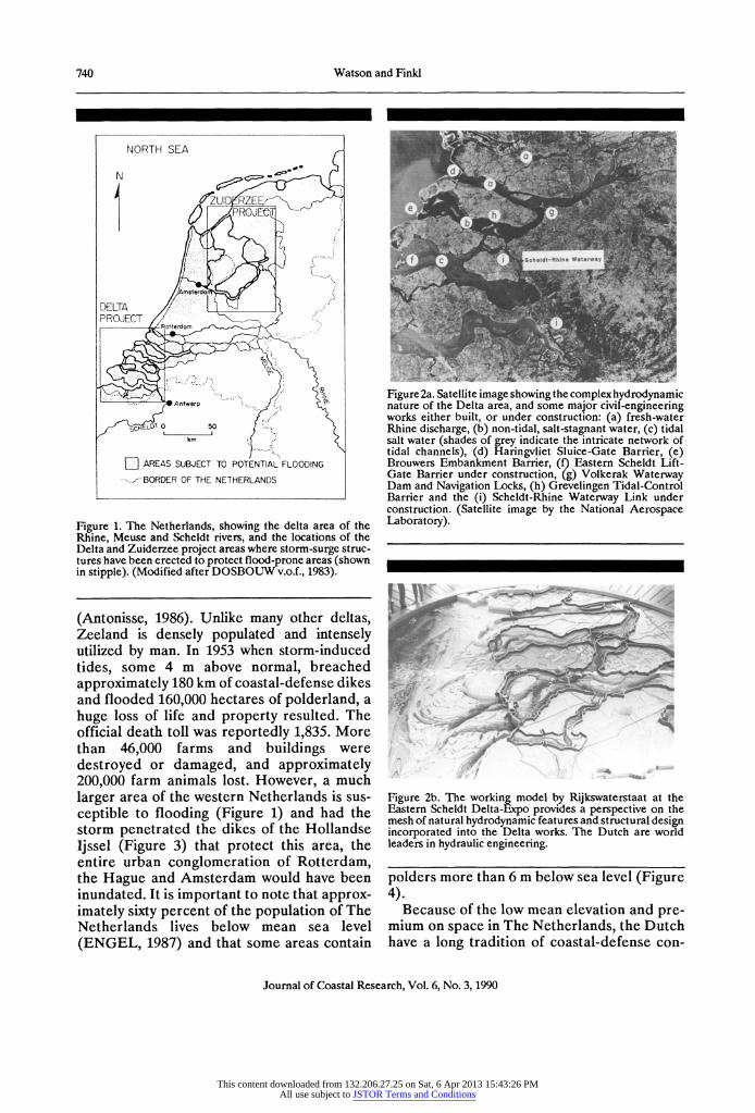
The Netherlands Delta Project covers a multi-river delta area created by the Rhine, Meuse and Scheldt (Figure 1). Like most delta-estuarine environments, this area repre- sents, in its natural state, an extremely complex
hydrodynamic regime encompassing fast-flow- ing tidal channels, changing estuarine con- figurations, nonhomogeneous subbottom sediments, a prolific, but delicately-balanced ecosystem, and low-land areas subject to peri- odic flooding (Figures 1 and 2).
Major storm-surge floods occurred in 1953, 1916, 1912, 1906, 1894, 1825,1808, 1775 and 1717
This content downloaded from 132.206.27.25 on Sat, 6 Apr 2013 15:43:26 PMAll use subject to JSTOR Terms and Conditions
740 Watson and Finkl
NORTH SEA
4N eZUID RZE
S PROJ
DELTA PROJECT Rotterdom
Antwerp
km AREAS SUBJECT TO POTENTIAL'FLOODING
.. BORDER OF THE NETHERLANDS
Figure 1. The Netherlands, showing the delta area of the Rhine, Meuse and Scheldt rivers, and the locations of the Delta and Zuiderzee project areas where storm-surge struc- tures have been erected to protect flood-prone areas (shown in stipple). (Modified after DOSBOUW v.o.f., 1983).
(Antonisse, 1986). Unlike many other deltas, Zeeland is densely populated and intensely utilized by man. In 1953 when storm-induced tides, some 4 m above normal, breached approximately 180 km of coastal-defense dikes and flooded 160,000 hectares of polderland, a huge loss of life and property resulted. The official death toll was reportedly 1,835. More than 46,000 farms and buildings were destroyed or damaged, and approximately 200,000 farm animals lost. However, a much larger area of the western Netherlands is sus- ceptible to flooding (Figure 1) and had the storm penetrated the dikes of the Hollandse Ijssel (Figure 3) that protect this area, the entire urban conglomeration of Rotterdam, the Hague and Amsterdam would have been inundated. It is important to note that approx- imately sixty percent of the population of The Netherlands lives below mean sea level (ENGEL, 1987) and that some areas contain
Figure 2a. Satellite image showing the complex hydrodynamic nature of the Delta area, and some major civil-engineering works either built, or under construction: (a) fresh-water Rhine discharge, (b) non-tidal, salt-stagnant water, (c) tidal salt water (shades of grey indicate the intricate network of tidal channels), (d) Haringvliet Sluice-Gate Barrier, (e) Brouwers Embankment Barrier, (f) Eastern Scheldt Lift- Gate Barrier under construction, (g) Volkerak Waterway Dam and Navigation Locks, (h) Grevelingen Tidal-Control Barrier and the (i) Scheldt-Rhine Waterway Link under construction. (Satellite image by the National Aerospace Laboratory).
Figure 2b. The working model by Rijkswaterstaat at the Eastern Scheldt Delta-Expo provides a perspective on the mesh of natural hydrodynamic features and structural design incorporated into the Delta works. The Dutch are world leaders in hydraulic engineering.
polders more than 6 m below sea level (Figure 4).
Because of the low mean elevation and pre- mium on space in The Netherlands, the Dutch have a long tradition of coastal-defense con-
Journal of Coastal Research, Vol. 6, No. 3, 1990
This content downloaded from 132.206.27.25 on Sat, 6 Apr 2013 15:43:26 PMAll use subject to JSTOR Terms and Conditions

Storm-Surge Protection in The Netherlands 741
E S
Figure 3. Major components of the Delta Project: (A) Brouwers Fixed Barrier, (B) Haringvliet Sluice-Gate Barrier and Navigation Lock, (C) Volkerak Waterway Dam and Navigation Locks, (D) Hollandse Ijssel Drop Barrier, (E) Zandkreek Dam, (F) Veerse Fixed Barrier, (G) Grevelingen Tidal-Control Dam, Lock, and Siphon Sluice, (H) Eastern Scheldt Lift-Gate Barrier, (I) Philips Waterway Dam and Krammer Navigation Locks and (J) Oester Waterway Closure Dam and Navigation Lock. Refer to Table 1 for a more complete description of these components. (Map after DOSBOUW v.o.f., 1983).
struction and land reclamation. This coastal conscientiousness dates back from farm houses built on artifical mounds around 400 BC, to ma- jor dike works built in the eleventh and twelfth century (WALTHER, 1987). The need for con- tinual coastal construction has intensified over the years as a result of population growth, land
Figure 4. Approximately 60 percent of the population of The Netherlands live in dike- and/or barrier-protected areas below mean sea level.
subsidence and rising sea levels. The people of The Netherlands have responded to the chal- lenge of coastal protection with projects such as the Zuiderzee Works (Figures 1 and 5), enclosed in 1932 but still in the process of having approximately 150,000 ha of new land reclaimed and, more recently, the Delta Plan formalized in 1958 by an act of the Dutch par- liament. The latter scheme became functional, in terms of storm-protection, in 1986 but con- siderable construction effort is still required on roads, bridges and other secondary struc- tures to complete the project. The continued maintenance and improvement of dikes and waterways remain a life-long preoccupation.
The core of the Delta Project called for the raising of existing dikes, the storm closure of all main tidal estuaries and inlets, but with provision for continued international shipping access to Rotterdam and Antwerp, a non-tidal inland waterway link between these two ports and last but not least, an integrated network of dams, salt/fresh-water separation locks and flushing mechanisms to separate and manage the salt and fresh-water environments in the Delta (Table 1).
Journal of Coastal Research, Vol. 6, No. 3, 1990
This content downloaded from 132.206.27.25 on Sat, 6 Apr 2013 15:43:26 PMAll use subject to JSTOR Terms and Conditions

742 Watson and Finkl
Table 1. Summnary of the major project components of the complete Delta Works, presenting the construction sequence, and the type and purpose of individual structures.
.f..t M..O. PRJECTC(...PONtNI. TC..ON...T..CTIOM PURPOSE
1 1958 HOLLANDSE USSEL P OGuillotine steel-pte drop barrier Open Mode: Facilitates navigation & Rhine Drop Barrier Navigation lock discharge (?250 (?250 m /sec)
Closed Mode: Storm-surge flood protection
2 1960 ZANDKREEK S Calmo-core & dredged-sand embankment Reduced tidal-current velocity for construction Tidal-Control Dam dam & of primary Veerse barrier
Provides navigation to stagnant Lake Veerse Navipgtion Lock
3 1961 VEERSE F Caisson-core & primary dredged-sand em- Storm-surge estuary closure (with Zankreek Fixed Barrier bankment dam, with asphalt cover Dam creates Lake Veerse)
S Combination cableway block & caisson core, Reduced tidal-current velocity for construction 4 1965 GREVELINGEN with dredged-sand dam; of Brouwers barrier
Tidal-Control Dam, Lock, & Siphon Sluice Artificial island for navigation lock & Facilitates navigation access to Lake Grevelin-
gen Flushing siphon sluice
Siphon helps flush Lake Grevelingen S Artificial-island & coffer-dam construction on Reduced tidal-current velocity for construction
5 1970 VOLKERAK large lock complex (two locks for commercial of Haringvliet barrier Waterway Dam & Navigation Locks traffic, one lock for pleasure craft)
Contributes to Scheldt-Rhine non-tidal water- way link
P Artificial-island & coffer-dam construction on Closed Mode: Storm-surge barrier 6 1971 HARINGVLIET piled piers, for pivot-gate sluice barrier
Sluice-Gate Barrier & Navigation Lock Part Closed & Open: Rhine discharge (fresh- Also cableway block-core embankment section water management)
Shipping access to North Sea
F South Channel: Cableway block core with Fixed storm-surge estuary closure, sluice & 7 1972 BROUWERS dredged-sand embankment dam crest road
Fixed Barrier Central: Dredge-improved sand bank
North Channel: Caisson core & sand embank- ment
S Core of riprap and gravel placed by barge & Closure forms part of the Scheldt-Rhine water- 8 1983 MAROUISATE QUAY truck dump way link
Waterway Closure Dam Core partially replaced by dredged-sand fill Reduced tidal velocity for Oester Dam con-
struction &
Controls salt-water intrusion to the east
P Two dredge-improved artificial islands Closed Mode: Storm-surge flood protection 9 1986 EASTERN SCHELDT
Lift-Gate Barrier Three sections of pier-and-lift-gate sluice bar- Open Mode: Tidal flushing for preservation of rier salt-water estuary
Shipping access to North Sea
S Large-scale artificial-island & coffer-dam con- Contributes to non-tidal conditions in the 10 1987 PHILIPS Waterway Dam & struction of Krammer Lock Complex Scheldt-Rhine waterway
KRAMMER Navigation Locks Dredged-sand embankment closure Krammer Locks provide shipping access to
Eastern Scheldt, but preserves salt-water east- ern Scheldt & fresh-water waterway
S Artificial-island & coffer-dam construction of Part of Scheldt-Rhine compartmentalization 11 1987 OESTER Waterway navigation lock closure
Closure Dam & Navigation Lock Dredged-sand embankment closure Facilitates shipping access between waterway
and the Eastern Scheldt
Controls salt-water intrusion to the east
P = Primary storm-surge control barrier, F = Primary storm-surge fixed embankment dam; S = Secondary tidal-control and/or waterway embankment
Much has been written about various aspects of the Delta Project and the purpose of this case-history review is to summarize important features of engineering-geologic application, in particular, remedial works that were imple- mented to cope with potential foundation prob- lems. The references cited address related aspects of investigation, design and construction in greater technical detail than the present text.
GEOLOGY AND FOUNDATION PROBLEMS
"It is pointless to try to increase the accuracy of prediction (of foundation stability) by 10 percent using advanced methods while soil pa- rameters may vary between 100 and 300 per- cent." (NIEUWENHUIS, 1987a).
Overview
Both the nature of the project and the geol- ogy of the area precluded the usual option of relocating structures to sites of significantly better foundation conditions. In the western
This content downloaded from 132.206.27.25 on Sat, 6 Apr 2013 15:43:26 PMAll use subject to JSTOR Terms and Conditions
Storm-Surge Protection in The Netherlands 743
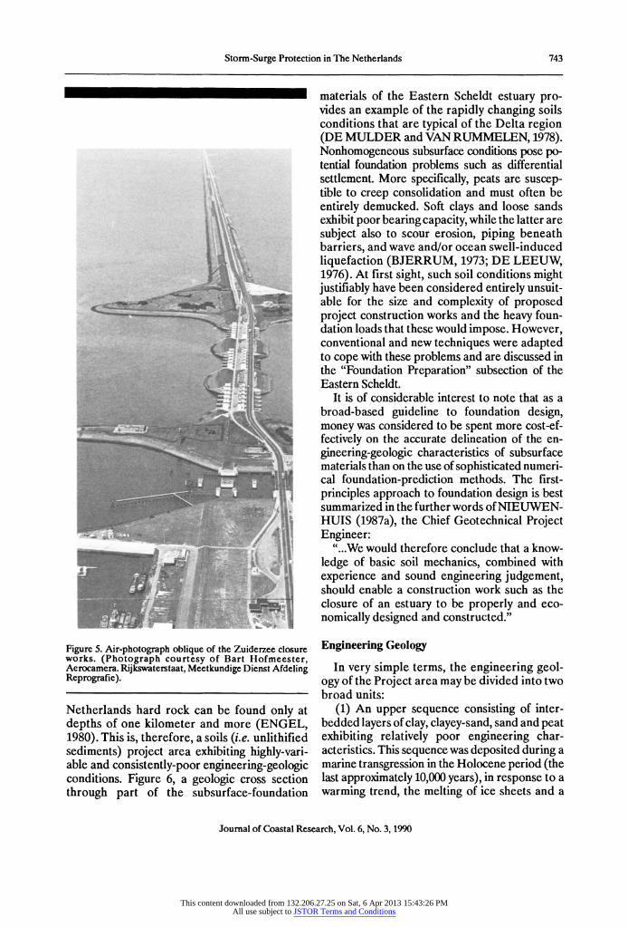
Figure 5. Air-photograph oblique of the Zuiderzee closure works. (Photograph courtesy of Bart Hofmeester, Aerocamera. Rijkswaterstaat, Meetkundige Dienst Afdeling Reprografie).
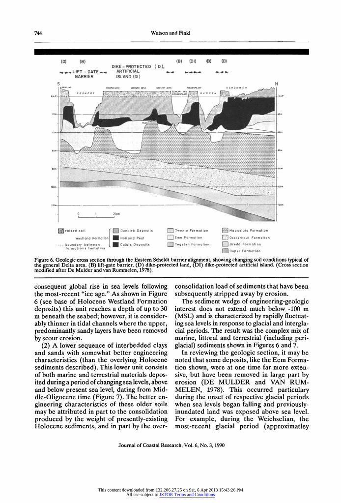
Netherlands hard rock can be found only at depths of one kilometer and more (ENGEL, 1980). This is, therefore, a soils (i.e. unlithified sediments) project area exhibiting highly-vari- able and consistently-poor engineering-geologic conditions. Figure 6, a geologic cross section through part of the subsurface-foundation
materials of the Eastern Scheldt estuary pro- vides an example of the rapidly changing soils conditions that are typical of the Delta region (DE MULDER and VAN RUMMELEN, 1978). Nonhomogeneous subsurface conditions pose po- tential foundation problems such as differential settlement. More specifically, peats are suscep- tible to creep consolidation and must often be entirely demucked. Soft clays and loose sands exhibit poor bearing capacity, while the latter are subject also to scour erosion, piping beneath barriers, and wave and/or ocean swell-induced liquefaction (BJERRUM, 1973; DE LEEUW, 1976). At first sight, such soil conditions might justifiably have been considered entirely unsuit- able for the size and complexity of proposed project construction works and the heavy foun- dation loads that these would impose. However, conventional and new techniques were adapted to cope with these problems and are discussed in the "Foundation Preparation" subsection of the Eastern Scheldt.
It is of considerable interest to note that as a broad-based guideline to foundation design, money was considered to be spent more cost-ef- fectively on the accurate delineation of the en- gineering-geologic characteristics of subsurface materials than on the use of sophisticated numeri- cal foundation-prediction methods. The first- principles approach to foundation design is best summarized in the further words of NIEUWEN- HUIS (1987a), the Chief Geotechnical Project Engineer:
"...We would therefore conclude that a know- ledge of basic soil mechanics, combined with experience and sound engineering judgement, should enable a construction work such as the closure of an estuary to be properly and eco- nomically designed and constructed."
Engineering Geology
In very simple terms, the engineering geol- ogy of the Project area may be divided into two broad units:
(1) An upper sequence consisting of inter- bedded layers of clay, clayey-sand, sand and peat exhibiting relatively poor engineering char- acteristics. This sequence was deposited during a marine transgression in the Holocene period (the last approximately 10,000 years), in response to a warming trend, the melting of ice sheets and a
Journal of Coastal Research, Vol. 6, No. 3, 1990
This content downloaded from 132.206.27.25 on Sat, 6 Apr 2013 15:43:26 PMAll use subject to JSTOR Terms and Conditions
744 Watson and Finki
(D) (B) (B) (DI) 1 B) (D) DIKE-PROTECTED ( D),
.., LIFT - GATE ,..
ARTIFICIAL BARRIER ISLAND (DI)
S N
I - t 0 ? 4.tW A- 7-..
7- 7 ' A'
.
4,A"
1*,
' 7 A
)T
T..,e- e Forrcl.. r--... , .e CS 00 s
s_ mc/
, ."
j.jt_~^li.;l.llcl?ll.lll .• , .: ~ - .. .... ...1 __~~ .......... . .
1":1
IL 'h _______
I IiII JIfff{ Ilp Tr
lT1J l
I
wres!!cr d F3 1. )1ct n: c c Pe 0 Eee Fo-'r ci'o ncster cu!' Fc rn ior',
- o.ndc- • ... .ee
. 1
c
.... eposits
_ ege .e. t.o
o c!o 3 Bredc Fo-nction
fc'mctjors te'•tct ve E]] Pqup e? Forrr tol of
Figure 6. Geologic cross section through the Eastern Scheldt barrier alignment, showing changing soil conditions typical of the general Delta area. (B) lift-gate barrier, (D) dike-protected land, (DI) dike-protected artificial island. (Cross section modified after De Mulder and van Rummelen, 1978).
consequent global rise in sea levels following the most-recent "ice age." As shown in Figure 6 (see base of Holocene Westland Formation deposits) this unit reaches a depth of up to 30 m beneath the seabed; however, it is consider- ably thinner in tidal channels where the upper, predominantly sandy layers have been removed by scour erosion.
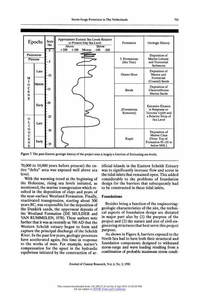
(2) A lower sequence of interbedded clays and sands with somewhat better engineering characteristics (than the overlying Holocene sediments described). This lower unit consists of both marine and terrestrial materials depos- ited during a period of changing sea levels, above and below present sea level, dating from Mid- dle-Oligocene time (Figure 7). The better en- gineering characteristics of these older soils may be attributed in part to the consolidation produced by the weight of presently-existing Holocene sediments, and in part by the over-
consolidation load of sediments that have been subsequently stripped away by erosion.
The sediment wedge of engineering-geologic interest does not extend much below -100 m (MSL) and is characterized by rapidly fluctuat- ing sea levels in response to glacial and intergla- cial periods. The result was the complex mix of marine, littoral and terrestrial (including peri- glacial) sediments shown in Figures 6 and 7.
In reviewing the geologic section, it may be noted that some deposits, like the Eem Forma- tion shown, were at one time far more exten- sive, but have been removed in large part by erosion (DE MULDER and VAN RUM- MELEN, 1978). This occurred particulary during the onset of respective glacial periods when sea levels began falling and previously- inundated land was exposed above sea level. For example, during the Weichselian, the most-recent glacial period (approximatley
Journal of Coastal Research, Vol. 6, No. 3, 1990
This content downloaded from 132.206.27.25 on Sat, 6 Apr 2013 15:43:26 PMAll use subject to JSTOR Terms and Conditions
Storm-Surge Protection in The Netherlands 745
Approximate Eustatic Sea Levels Relative Epochs Scale to Present-Day Sea Level Formation Geologic History
Ma Above Below 0- +200 +100 Meters -100 -200
Pleistocene " Deposition of
Pliocene - 5 Formations Marine Littoral -5 (See Text) and Terrestrial
Sediments
Late - Deposition of -10 Ooster Hout Marine and
M - Terrestrial I - (Coastal) Sands O Middle -
C iDeposition of E-15 Breda Glauconiferous N
- Marine Sands
E 20
Early 2 Extensive Erosion (Formations in Response to Removed) Tectonic Uplift and
-25 a Relative Drop of O0- Sea Level L Late " I
O - Deposition of C
- - I Marine Clays
E Rupel (Note: Top of N Early Formation 95-135 m E 35 below MSL)
Figure 7. The post-Eocene geologic history of the project area is largely a function of fluctuating sea levels.
70,000 to 10,000 years before present) the en- tire "delta" area was exposed well above sea level.
With the warming trend at the beginning of the Holocene, rising sea levels initiated, as mentioned, the marine transgression which re- sulted in the deposition of clays and peats of the near-surface Westland Formation. Finally, reactivated transgression, starting about 500 years BC, was responsible for the deposition of the Dunkirk sands, the uppermost deposits of the Westland Formation (DE MULDER and VAN RUMMELEN, 1978). These authors note further that it was as recently as 700 AD that the Western Scheldt estuary began to form and capture the principal discharge of the Scheldt River. In the past few years, geologic processes have accelerated again, this time in response to the works of man. For example, nature's compensation for the upset in the hydraulic equibrium initiated by the construction of ar-
tificial islands in the Eastern Scheldt Estuary was to significantly increase flow and scour in the tidal inlets that remained open. This added considerably to the problems of foundation design for the barriers that subsequently had to be constructed in these tidal inlets.
Foundations
Besides being a function of the engineering- geologic characteristics of the site, the techni- cal aspects of foundation design are dictated in major part also by (1) the purpose of the project and (2) the nature and size of civil-en- gineering structures that best serve this project purpose.
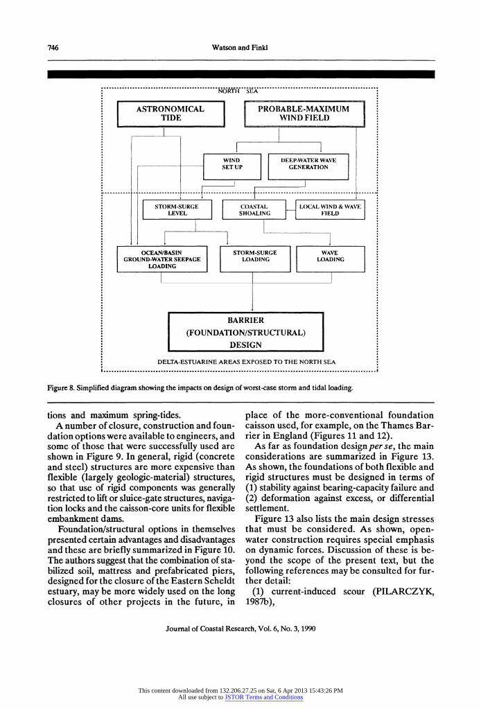
As shown in Figure 8, barriers exposed to the North Sea had to have both their structural and foundation components designed to withstand storm-surge and wave loading resulting from a combination of probable maximum storm condi-
Journal of Coastal Research, Vol. 6, No. 3, 1990
This content downloaded from 132.206.27.25 on Sat, 6 Apr 2013 15:43:26 PMAll use subject to JSTOR Terms and Conditions
746 Watson and Finkl
ASTRONOMICAL PROBABLE-MAXIMUM TIDE WIND FIELD
WIND I)EE P-WATER WAVE SET UP GENERATION
STORM-SURGE COASTAL LOCAL WIND & WAVE LEVEL SHOALING FIELD
S OCEAN/BASIN STORM-SURGE WAVE GROUND-WATER SEEPAGE LOADING LOADING
-' LOADING
BARRIER
(FOUNDATION/STRUCTURAL) DESIGN
DELTA-ESTUARINE AREAS EXPOSED TO THE NORTH SEA
Figure 8. Simplified diagram showing the impacts on design of worst-case storm and tidal loading.
tions and maximum spring-tides. A number of closure, construction and foun-
dation options were available to engineers, and some of those that were successfully used are shown in Figure 9. In general, rigid (concrete and steel) structures are more expensive than flexible (largely geologic-material) structures, so that use of rigid components was generally restricted to lift or sluice-gate structures, naviga- tion locks and the caisson-core units for flexible embankment dams.
Foundation/structural options in themselves presented certain advantages and disadvantages and these are briefly summarized in Figure 10. The authors suggest that the combination of sta- bilized soil, mattress and prefabricated piers, designed for the closure of the Eastern Scheldt estuary, may be more widely used on the long closures of other projects in the future, in
place of the more-conventional foundation caisson used, for example, on the Thames Bar- rier in England (Figures 11 and 12).
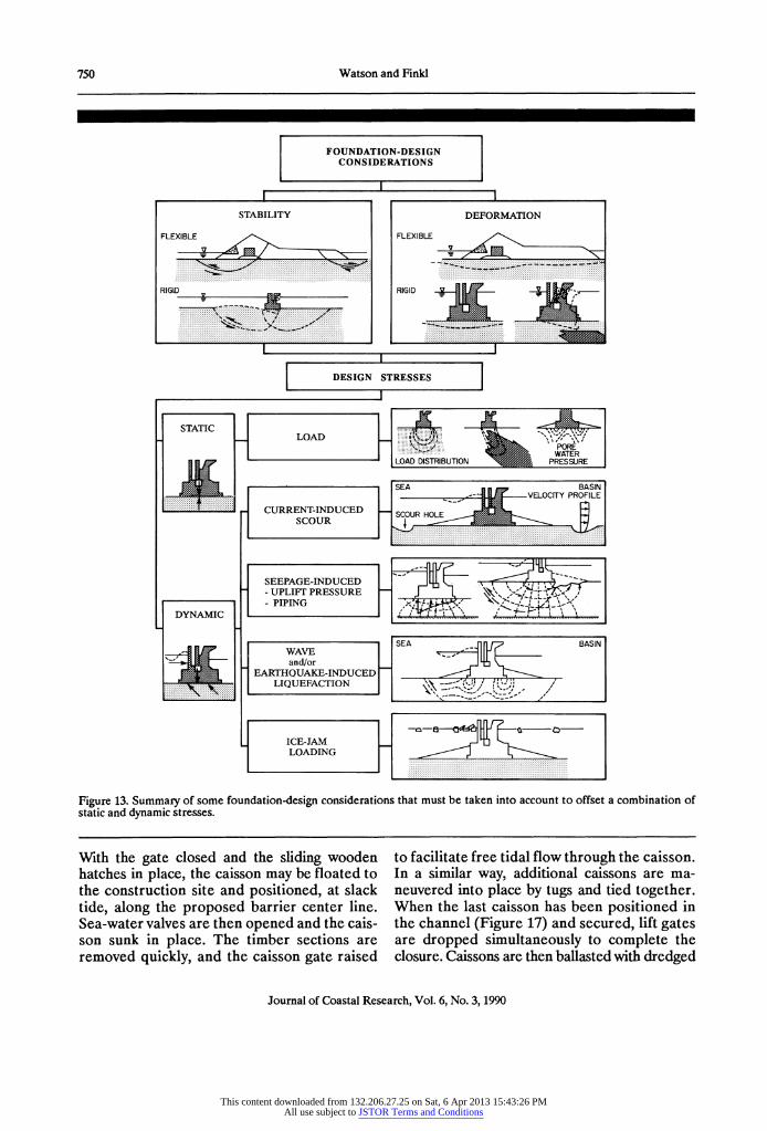
As far as foundation design per se, the main considerations are summarized in Figure 13. As shown, the foundations of both flexible and rigid structures must be designed in terms of (1) stability against bearing-capacity failure and (2) deformation against excess, or differential settlement.
Figure 13 also lists the main design stresses that must be considered. As shown, open- water construction requires special emphasis on dynamic forces. Discussion of these is be- yond the scope of the present text, but the following references may be consulted for fur- ther detail:
(1) current-induced scour (PILARCZYK, 1987b),
Journal of Coastal Research, Vol. 6, No. 3, 1990
This content downloaded from 132.206.27.25 on Sat, 6 Apr 2013 15:43:26 PMAll use subject to JSTOR Terms and Conditions

Storm-Surge Protection in The Netherlands 747
CLOSURE OPTIONS
RIGID SIRUCIURE IFLZEXIBLE SIRUCI1URE
e.g. Caisson or Monolithic Pier e.g. Sand Embankment
(May require rigid-component core)
CONSTRUCTION OPTIONS
PREFABRICATED ON-SITE DREDGED-SAND CABLEWAY
COMPONENIiS (COFF1RDAM) EMBANKMENT C D
LOCP OR CONSIRUCnION (rigid caisson core) RUBBLE
FOUNDATION OPTIONS
STABILIZED SOIL PILES EROSION MATTRESS PILE-SUPPORTED
Protected by: Protected by rock rubble Protection for core cais- Cableway piers; possible Erosion mats Non-piled foundation sons mat protection of seabed
Graded filter protected byernosion mats (e.g. Veerse Dam) (e.g. South cction of Rock sill (e.g. Hlaringeliet dis- Brouwers Dam) Rock sill
charge sluices) (e.g. Eastern Scheidt)
Figure 9. Some closure, construction and foundation options available to Delta-Project design engineers.
(2) seepage-induced uplift pressures and pi- ping (PILARCZYK, 1987a; v.d. BURG and NIEUWENHUIS, 1987),
(3) wave and/or earthquake induced liquefac- tion (AMBRAYSEYS AND SARMA, 1967; DE LEEUW, 1976; NIEUWENHUIS, 1987B; SEED, 1979; VAN AALST and BRUINSMA, 1987) and
(4) ice-jam loading (PILARCZYK, 1987a). General discussion, including design against
static-loading conditions, may be found in BJERRUM, 1973; BRUUN and JOHANNES- SON, 1976; BRUUN and KJELSTRUP, 1981; SMITS, et al., 1978.
PLANNING AND CONSTRUCTION SEQUENCE
An important ingredient in the planning of the project was to follow a construction sequence
(where practical) that was predicated by least- to-most-complicated design requirements. This simple philosophy enabled relatively rapid pro- gress to be made at the outset of the project, and established a learning process that proved in- valuable in the latter stages of construction.
The sequence, type and purpose of construc- tion of major components of the scheme are presented in Table 1. This highlights a major technical factor influencing the construction sequence, namely the need to reduce tidal-cur- rent velocities in the four main estuaries be- fore the construction of primary barriers could be undertaken. Tidal velocities were lowered by constructing secondary compartmentaliza- tion barriers (e.g. Zandkreek Dam, Grevelin- gen Dam, and Volkerak Dam - Figure 3) to reduce the extent of the Delta area subject to tidal influence (RIJKSWATERSTAAT, 1987). This resulted, in turn, in a reduced tidal vol- ume and, therefore, lower current velocities through the main estuaries.
Journal of Coastal Research, Vol. 6, No. 3, 1990
This content downloaded from 132.206.27.25 on Sat, 6 Apr 2013 15:43:26 PMAll use subject to JSTOR Terms and Conditions

748 Watson and Finkl
.. . . . . . . .... . . . . . . .. . . . . . . ..:. ..:
:::::::::: : : : : : . .* . . . . . .. . . . . ..: :.
. . . ..:::::::::::::::::::
. . ..:::::::::::::::::: :::.:::::::::::::: :.:.. . . . .* ..:. . . . . . . . . . ..::A::::::::::::
NORTH SW SEA NETHERLANDS
MINIMAL FOUNDA- LONG PERIOD OF PILES SUPPORTING TION OPEN-WATER AND/OR CAISSONS OR PIERS PREPARATION COFFERDAM
CONSTRUCTION LARGE FACTOR OF
SAFETY
FACILITATES REQUIRES STRINGENT STABILIZED SOIL MAXIMUM USE OF PRE QUALITY CONTROL
(PROTECTED) FABRICATED COM- ON: SUPPORTING CAISSONS PONENTS Soil Stabilization (e.g.
OR compaction & density) MONOLITHIC PIERS MINIMIZES DEEP-
WATER CONSTRUC- FOUNDATION TION TIME PREPARATION
(e.g. levelling)
FOUNDATION MINIMAL FOUNDA- TIME CONSUMING & CAISSONS [TION LABOR-INTENSIVE
SUPPORTING PIERS OR PREPARATION UNDER DIFFICULT & CAISSONS FATRF POTENTIALLY
. . LAR.GE FACTOR OF DANGEROUS ON-SITE SAFETY CONDITIONS
Figure 10. Advantages and disadvantages of some foundation/structural options.
It may be noted further, that secondary com- partmentalization works also served the dual purpose of (1) impounding the Rhine/Scheldt water way and (2) creating a fresh-water buff- er zone to inhibit salt-water intrusion from the Delta region to the agricultural areas east of Bergen Op Zoom (Figure 3).
All of this construction, in turn, imposed a new environmental regime on the Delta, that relies for its preservation on the design of a complex support system of flushing structures. A good example is provided by Lake Grevelin- gen, where a desirable salt content is main- tained by circulating sea water though an inlet sluice in Brouwers Dam (Figure 14), and dis- charging excess water from the Lake to the Eastern Scheldt with a siphon sluice built into Grevelingen Dam (Figure 15).
With respect to planning the construction se- quence for individual structures, it is important to remember that the preparation of complex foundation sections consumed a high proportion of the total construction time. The schedule shown for completion of the Roompot channel
in the Eastern Scheldt is typical (Figure 16). This figure shows approximately 80 percent of construction time (not including site investiga- tion) spent on compaction and other soil-im- provement procedures, building of the foundation bed, and completion of the rock-rubble sill to protect the foundations of the gate-piers (VAN DER SCHAAF and OFFRINGA, 1980).
METHODS OF CONSTRUCTION
Rather than discuss in detail each of the pro- ject components summarized in Table 1, the con- struction-methods used for these various structures are outlined under three subheadings: (1) primary embankment dams, (2) artificial is- lands and cofferdams, and (3) secondary struc- tures (gravel-and-sand-embankment dams). A fourth method employing prefabricated mono- lithic piers on a stabilized foundation is discussed in the section on the Eastern Scheldt.
Journal of Coastal Research, Vol. 6, No. 3, 1990
This content downloaded from 132.206.27.25 on Sat, 6 Apr 2013 15:43:26 PMAll use subject to JSTOR Terms and Conditions
Storm-Surge Protection in The Netherlands 749
R eeRocrkr BReam
A__ac eL to
C-co t concrete co cr.te Pie, cast ,o Ii119 S,, Set or Rubber,
4 5rr Deep Sheetrpied Pa, in Ricer Bed
-p
d I; ising Sector C
Foundation
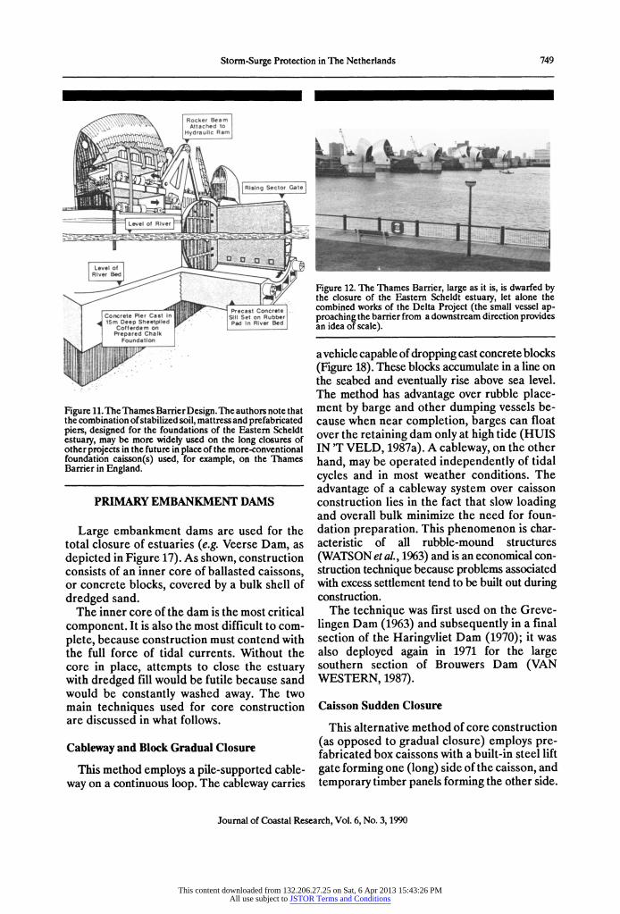
Figure 11. The Thames Barrier Design. The authors note that the combination of stabilized soil, mattress and prefabricated piers, designed for the foundations of the Eastern Scheldt estuary, may be more widely used on the long closures of other projects in the future in place of the more-conventional foundation caisson(s) used, for example, on the Thames Barrier in England.
PRIMARY EMBANKMENT DAMS
Large embankment dams are used for the total closure of estuaries (e.g. Veerse Dam, as depicted in Figure 17). As shown, construction consists of an inner core of ballasted caissons, or concrete blocks, covered by a bulk shell of dredged sand.
The inner core of the dam is the most critical component. It is also the most difficult to com- plete, because construction must contend with the full force of tidal currents. Without the core in place, attempts to close the estuary with dredged fill would be futile because sand would be constantly washed away. The two main techniques used for core construction are discussed in what follows.
Cableway and Block Gradual Closure
This method employs a pile-supported cable- way on a continuous loop. The cableway carries
Figure 12. The Thames Barrier, large as it is, is dwarfed by the closure of the Eastern Scheldt estuary, let alone the combined works of the Delta Project (the small vessel ap- proaching the barrier from a downstream direction provides an idea of scale).
a vehicle capable of dropping cast concrete blocks (Figure 18). These blocks accumulate in a line on the seabed and eventually rise above sea level. The method has advantage over rubble place- ment by barge and other dumping vessels be- cause when near completion, barges can float over the retaining dam only at high tide (HUIS IN 'T VELD, 1987a). A cableway, on the other hand, may be operated independently of tidal cycles and in most weather conditions. The advantage of a cableway system over caisson construction lies in the fact that slow loading and overall bulk minimize the need for foun- dation preparation. This phenomenon is char- acteristic of all rubble-mound structures (WATSON et al., 1963) and is an economical con- struction technique because problems associated with excess settlement tend to be built out during construction.
The technique was first used on the Greve- lingen Dam (1963) and subsequently in a final section of the Haringvliet Dam (1970); it was also deployed again in 1971 for the large southern section of Brouwers Dam (VAN WESTERN, 1987).
Caisson Sudden Closure
This alternative method of core construction (as opposed to gradual closure) employs pre- fabricated box caissons with a built-in steel lift gate forming one (long) side of the caisson, and temporary timber panels forming the other side.
Journal of Coastal Research, Vol. 6, No. 3, 1990
This content downloaded from 132.206.27.25 on Sat, 6 Apr 2013 15:43:26 PMAll use subject to JSTOR Terms and Conditions
750 Watson and Finkl
FOUNDATION-DESIGN CONSIDERATIONS
I I STABILITY DEFORMATION
FLEXIBLE FLEXIBLE
RIGID . . .RIGID
....... ..............iii i ii iiii i i ii -ii•. . . . . . . .
I. . I
DESIGN STRESSES
I
STATICLOAD :::::~~i~Sij ~ WATER
v LOAD DISTRIBUT ON PRESSURE
, .o
.........
ii, , .. ,
.... .. ...
,.
.. ..
.... VELOCITY PROFILE
CURRENT-INDUCED --
SCOURR HOLE
D Y N A IC........ .."..."".".." '.... ........ .....J
...... ""...
.. I..... •.... ....
SEEPAGE-INDUCED - UPLIFT PRESSURE
D N I - PIPING -: .. .
SEA BASIN WAVE
and/or
EARTHOUAKE-INDUCED
titii~iiiit~~iiiitr~~iLIQUEFACTION --,
ICE-JAM LOADING
Figure 13. Summary of some foundation-design considerations that must be taken into account to offset a combination of static and dynamic stresses.
With the gate closed and the sliding wooden hatches in place, the caisson may be floated to the construction site and positioned, at slack tide, along the proposed barrier center line. Sea-water valves are then opened and the cais- son sunk in place. The timber sections are removed quickly, and the caisson gate raised
to facilitate free tidal flow through the caisson. In a similar way, additional caissons are ma- neuvered into place by tugs and tied together. When the last caisson has been positioned in the channel (Figure 17) and secured, lift gates are dropped simultaneously to complete the closure. Caissons are then ballasted with dredged
Journal of Coastal Research, Vol. 6, No. 3, 1990
This content downloaded from 132.206.27.25 on Sat, 6 Apr 2013 15:43:26 PMAll use subject to JSTOR Terms and Conditions
Storm-Surge Protection in The Netherlands 751
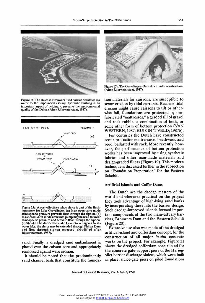
Figure 14. The sluice in Brouwers fixed barrier circulates sea water to the impounded estuary; hydraulic flushing is an important aspect of helping to preserve the environmental quality of the Delta. (After Rijkswaterstaat, 1987).
LAKE GREVELINGEN KRAMMER
VALVE OPEN
,/ (a)
FLOW ACTIVATED BY
VACUUM PUMP VALVE CLOSED
(b)
tAh
(c)
............
. . . . . . . . . . . . . . . . . . . . . .. ..... : . . . . . . . . . . . . . . . . . . . . . . .
Figure 15a. A cost-effective siphon sluice is part of the flush- ing system for Lake Grevelingen. (a) In an open-valve mode atmospheric pressure prevents flow through the siphon. (b) In a closed-valve mode a vacuum pump may be used to lower atmospheric pressure and activate flow through the siphon. (c) Should it be decided to make Lake Grevelingen a fresh- water lake, the sluice may be extended through Philips Dam and flow through siphon reversed. (Modified after Rijkswaterstaat, 1987).
sand. Finally, a dredged sand embankment is placed over the caisson core and appropriately reinforced against wave erosion.
It should be noted that the predominantly sand channel beds that constitute the founda-
Figure 15b. The Grevelingen-Dam sluice under construction. (After Rijkswaterstaat, 1987).
tion materials for caissons, are susceptible to scour erosion by tidal currents. Because tidal erosion might cause caissons to tilt or other- wise fail, foundations are protected by pre- fabricated "mattresses," a graded sill of gravel and rock rubble, a combination of both, or some other form of bottom protection (VAN WESTERN, 1987; HUIS IN'T VELD; 1987b).
For centuries the Dutch have constructed scour-protection mattresses of brushwood and reed, ballasted with rock. More recently, how- ever, the performance of bottom-protection works has been improved by using synthetic fabrics and other man-made materials and design-graded filters (Figure 19). This modern technique is discussed further in the subsection on "Foundation Preparation" for the Eastern Scheldt.
Artificial Islands and Coffer Dams
The Dutch are the dredge masters of the world and wherever practical on the project they took advantage of high-lying sand banks by incorporating these into the barrier design. Such dredge-improved islands formed impor- tant components of the two main-estuary bar- riers, Brouwers Dam and the Eastern Scheldt (Figure 20).
Extensive use also was made of the dredged artifical-island and cofferdam concept, for the construction of all major in-situ concrete works on the project. For example, Figure 21 shows the dredged cofferdam constructed for the concrete gate-support piers of the Haring- vliet barrier discharge sluices, which were built in place; sluice-gate piers on piled foundations
Journal of Coastal Research, Vol. 6, No. 3, 1990
This content downloaded from 132.206.27.25 on Sat, 6 Apr 2013 15:43:26 PMAll use subject to JSTOR Terms and Conditions

752 Watson and Finkl
z o ROOMPOT
o on
o-4 .
op
o 8P
A o•
oo
........... o O.IL
o
APR - APRON
SUMPROVEMENT
0p
A A
DA71' Jv?? . .*.... IE 00c 00l;
0:;:: O :: 0 ..... ... 0;:: ... ..... .......... 0 0 0 :?:
44 ::
CA)
...... 0 .. .... . C'
0 0 ... -,.*
.,-*..
BP = lilill ill lilt, Ill 111111A
Figure 16. Construction sequence for the Roompot channel, Eastern Scheldt; note that about 80 percent of the total construction time was spent on foundation preparation. (After van der Schaaf and Offringa, 1980).
Figure 17. Veerse primary-embankment barrier showing: (a) tugs positioning the last caisson for the "sudden closure" core of the dam. (b) The approach embankment with a crest road; this will eventually extend over the caisson core. (Photog- raphy by Bart Hofmeester, Aerocamera. Rijkswaterstaat, Meetkundige Dienst Afdeling Reprografie).
were conveniently constructed in the dry. On completion, the cofferdam was flooded, removed and the sluice gates incorporated in the barrier dam.
Figure 22 shows a further example of the use of a dredged artificial island, for the cofferdam construction of the Krammer locks in the Philips Dam.
Secondary Structures
A great number of secondary embankment dams and transitional structures were built to serve as approaches for primary barrier closures, as connectors between barriers and dikes, or as compartmentalization structures for waterways. These consist essentially of dredge sand, rein- forced against erosion by one or a combination of asphalt, concrete, paved stone, or rip rap (SCHELLEKENS et al., 1980).
In the case of the Marquisate Quay, closed in the spring of 1983 (Figure 23) to serve as a section of the Scheldt-Rhine waterway (Figure 2), initial stone rip-rap construction was com- pleted by a combination of stone-dump barges, rubber-tired tip trucks and hydraulic scoop cranes. Once the rip-rap core was raised above water level, dredged sand was placed in such a way that a large volume of the (short-supply) rip rap could be conveniently removed for other sections of the project (RIJKSWATERSTAAT; 1987).
Journal of Coastal Research, Vol. 6, No. 3, 1990
This content downloaded from 132.206.27.25 on Sat, 6 Apr 2013 15:43:26 PMAll use subject to JSTOR Terms and Conditions

Storm-Surge Protection in The Netherlands 753
Figure 18. Cableway vehicle used to drop concrete blocks for the "gradual-closure" method of core construction for em- bankment barriers. (Rijkswaterstaat, Meetkundige Dienst Afdeling Reprografie).
EASTERN SCHELDT
Overview
The original master plan for the closing of the Eastern Scheldt estuary called for a complete closure, a primary embankment dam. However, to preserve the natural salt-water environment of the estuary, the design subsequently was changed to a sluice-gate barrier (ENGEL, 1980; DE JONG et al., 1987). The revised plan called for a control barrier consisting of some 65 pre- fabricated concrete piers to support sliding steel gates in the three tidal channels (which
Figure 19. A graded-filter foundation mattress constructed of both natural and synthetic materials offers protection against: (1) scour and currents, (2) piping (seepage erosion) induced by the differential head of water when barrier gates are closed, (3) excess pore water pressures caused by pier- placement loading and (4) liquefaction due to storm waves.
Figure 20a. The Dutch are the dredge masters of the world and frequently, as here in the Eastern Scheldt estuary, made use of artificial islands to facilitate cost-effective construc- tion. This photograph (looking south) shows two dredged islands: (a) Roggenplaat and (b) Neeltje Jans, originally used as a construction base, and presently home of the Delta-Expo museum. See Figure 20b for further details. (Photography by Bart Hoffmeester, Aerocamera. Rijkswaterstaat Meetkun- dige Dienst Afdeling Reprografie).
would remain after the completion of two large artificial islands, see Figure 20).
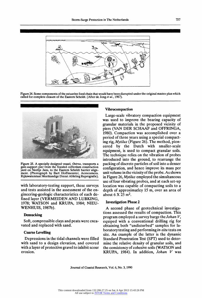
The new design, although vastly more com- plex from a technical standpoint, and consider- ably more expensive, facilitated the continued tidal flushing of the estuary, and was, therefore, justified on environmental grounds. Some examples of food chains in an estuarine web which would have been destroyed as the water behind a fixed dam gra-
Journal of Coastal Research, Vol. 6, No. 3, 1990
This content downloaded from 132.206.27.25 on Sat, 6 Apr 2013 15:43:26 PMAll use subject to JSTOR Terms and Conditions
754 Watson and Finkl
SEE GEOLOGIC N CROSS SECTION N
. SCHONUWE
N
HAMMEN
Construction- ..
300 island access bridge
ROGGENPLAAT 200
NORTH SEA
-.. SCHAAR
NEELTJE JANS'"
•-•
Cofferdam(s) for pier
DAMVAK GEUL • construction
.-5
NOORDLAND EASTERN SCHELDT
------BASIN
-20
k - 300
ROOMPOT 0 2km
-10 -- ' Depth in m. MSL
200o--w Precompletion discharge (m3/s)
St? NO~flO EVELAN
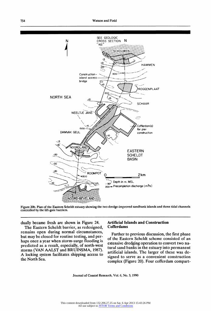
Figure 20b. Plan of the Eastern Scheldt estuary showing the two dredge-improved sandbank islands and three tidal channels controlled by the lift-gate barriers.
dually became fresh are shown in Figure 24. The Eastern Scheldt barrier, as redesigned,
remains open during normal circumstances, but may be closed for routine testing, and per- haps once a year when storm-surge flooding is predicted as a result, especially, of north-west storms (VAN AALST and BRUINSMA, 1987). A locking system facilitates shipping access to the North Sea.
Artificial Islands and Construction Cofferdams
Further to previous discussion, the first phase of the Eastern Scheldt scheme consisted of an extensive dredging operation to convert two na- tural sand banks in the estuary into permanent artificial islands. The larger of these was de- signed to serve as a convenient construction complex (Figure 20). Four cofferdam compart-
Journal of Coastal Research, Vol. 6, No. 3, 1990
This content downloaded from 132.206.27.25 on Sat, 6 Apr 2013 15:43:26 PMAll use subject to JSTOR Terms and Conditions
Storm-Surge Protection in The Netherlands 755
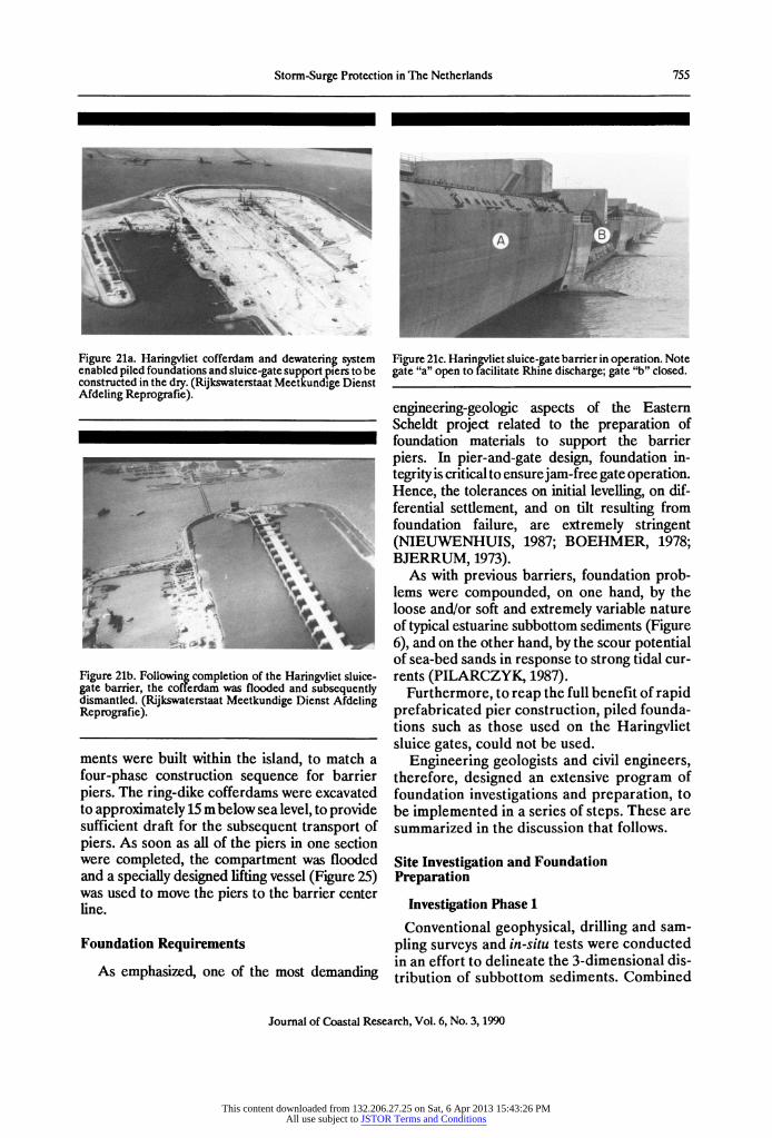
Figure 21a. Haringvliet cofferdam and dewatering system enabled piled foundations and sluice-gate support piers to be constructed in the dry. (Rijkswaterstaat Meetkundige Dienst Afdeling Reprografie).
Figure 21b. Following completion of the Haringvliet sluice- gate barrier, the cofferdam was flooded and subsequently dismantled. (Rijkswaterstaat Meetkundige Dienst Afdeling Reprografie).
ments were built within the island, to match a four-phase construction sequence for barrier piers. The ring-dike cofferdams were excavated to approximately 15 m below sea level, to provide sufficient draft for the subsequent transport of piers. As soon as all of the piers in one section were completed, the compartment was flooded and a specially designed lifting vessel (Figure 25) was used to move the piers to the barrier center line.
Foundation Requirements
As emphasized, one of the most demanding
Figure 21c. Haringvliet sluice-gate barrier in operation. Note gate "a" open to facilitate Rhine discharge; gate "b" closed.
engineering-geologic aspects of the Eastern Scheldt project related to the preparation of foundation materials to support the barrier piers. In pier-and-gate design, foundation in- tegrity is critical to ensure jam-free gate operation. Hence, the tolerances on initial levelling, on dif- ferential settlement, and on tilt resulting from foundation failure, are extremely stringent (NIEUWENHUIS, 1987; BOEHMER, 1978; BJERRUM, 1973).
As with previous barriers, foundation prob- lems were compounded, on one hand, by the loose and/or soft and extremely variable nature of typical estuarine subbottom sediments (Figure 6), and on the other hand, by the scour potential of sea-bed sands in response to strong tidal cur- rents (PILARCZYK, 1987).
Furthermore, to reap the full benefit of rapid prefabricated pier construction, piled founda- tions such as those used on the Haringvliet sluice gates, could not be used.
Engineering geologists and civil engineers, therefore, designed an extensive program of foundation investigations and preparation, to be implemented in a series of steps. These are summarized in the discussion that follows.
Site Investigation and Foundation Preparation
Investigation Phase 1
Conventional geophysical, drilling and sam- pling surveys and in-situ tests were conducted in an effort to delineate the 3-dimensional dis- tribution of subbottom sediments. Combined
Journal of Coastal Research, Vol. 6, No. 3, 1990
This content downloaded from 132.206.27.25 on Sat, 6 Apr 2013 15:43:26 PMAll use subject to JSTOR Terms and Conditions

756 Watson and Finkl
Figure 22. A further example of mega-scale cofferdam use for the construction of the pump house, support culverts and Krammer navigation lock system in the Philips dam. (After Rijkswaterstaat, 1987).
Figure 23a. A critical section of Marquisate Quay under construction on the Scheldt-Rhine waterway link. Note the strong tidal flow through placed-fill core materials in the closure dike. (After Rijkswaterstaat, 1987).
Figure 23b. A dredged-sand embankment over the rubble core completes the dike and eliminates a tidal influence on this section of the waterway. The Kreekrak lock system is in
Figure 23c. The 120 kilometer protected waterway between Rotterdam and Antwerp has created one of the busiest and most economical links in Europe for the transport of com- mercial cargo: this picture shows barges emerging from the Kreekrak locks. (After Rijkswaterstaat, 1987).
Journal of Coastal Research, Vol. 6, No. 3, 1990
This content downloaded from 132.206.27.25 on Sat, 6 Apr 2013 15:43:26 PMAll use subject to JSTOR Terms and Conditions
Storm-Surge Protection in The Netherlands 757
Figure 24. Some components of the estuarine food chain that would have been disrupted under the original master plan which called for complete closure of the Eastern Scheldt. (After de Jong et al., 1987).
Figure 25. A specially designed vessel, Ostrea, transports a gate-supprt pier from the flooded cofferdam construction yard on Neeltje Jans, to the Eastern Scheldt barrier align- ment. (Photograph by Bart Hoffmeester, Aerocamera. Rijkswaterstaat Meetkundige Dienst Afdeling Reprografie).
with laboratory-testing support, these surveys and tests assisted in the assessment of the en- gineering-geologic characteristics of each de- fined layer (VERMEIDEN AND LUBKING, 1978; WATSON and KRUPA, 1984; NIEU- WENHUIS, 1987b).
Demucking Soft, compressible clays and peats were exca-
vated and replaced with sand.
Coarse Levelling
Depressions in the tidal channels were filled with sand to a design elevation, and covered with a layer of protective gravel to inhibit scour erosion.
Vibrocompaction
Large-scale vibratory compaction equipment was used to improve the bearing capacity of granular materials in the proposed vicinity of piers (VAN DER SCHAAF and OFFRINGA, 1980). Compaction was accomplished over a period of three years using a special compact- ing rig, Mytilus (Figure 26). The method, pion- eered by the Dutch with smaller-scale equipment, is used to compact granular soils. The technique relies on the vibration of probes introduced into the ground, to rearrange the packing of discrete particles of soil into a denser configuration, and hence improve its mass per unit volume in the vicinity of the probe. As shown in Figure 26, Mytilus employed the simultaneous use of four vibrating probes, and at each set-up location was capable of compacting soils to a depth of approximatley 15 m, over an area of about 6 X 25 m2
Investigation Phase 2
A second phase of geotechnical investiga- tions assessed the results of compaction. This program employed a survey barge the Johan V, equiped with a conventional drilling rig for obtaining both "undisturbed" samples for la- boratory testing and performing in-situ tests on site. An example of the latter is the dynamic Standard Penetration Test (SPT) used to deter- mine the relative density of granular soils, and the consistency of cohesive soils (WATSON and KRUPA, 1984). In addition, Johan V was
Journal of Coastal Research, Vol. 6, No. 3, 1990
This content downloaded from 132.206.27.25 on Sat, 6 Apr 2013 15:43:26 PMAll use subject to JSTOR Terms and Conditions

758 Watson and Finkl
Figure 26. The Dutch are the pioneers of the vibrocompac- tion method used over a period of three years to improve the foundation characteristics of subbottom granular soils in the Eastern Scheldt estuary. Schematic diagram shows the spe- cially-designed craft Mytilus, which employed the simul- taneous use of four large-scale vibratory probes to achieve compaction. (After DOSBOUW v.o.f., 1983).
equipped with a diving bell which enabled in- situ seabed density measurements to be under- taken (VAN DER SCHAAF and OFFRINGA, 1980).
Anchor Piles
During construction a large number of ves- sels were required to work along the barrier alignment. Therefore, to prevent anchor dam- age to the prepared seabed, and to the erosion- protection mats that would subsequently be placed, underwater mooring piles were driven into the seabed. These were fitted with heavy mooring cables (attached to a marker buoy) which could be hauled aboard to secure a ves- sel for a particular task, and then cast off to rest on the seabed until needed again.
Erosion Mats
To protect the prepared seabed from severe erosion by tidal currents, a combination of poly- propylene and concrete-block mats, asphalt slabs and graded-filter mattresses were used. This protection followed the proposed barrier alignment and extended for approximately 500 m on either side of the center line. As shown in Figure 27, the concrete-weighted erosion mat
and asphalt slabs formed the outer periphery of the seabed protection apron, while the more expensive graded-filter mattresses, subse- quently discussed, were used under the gate- support piers.
Foundation Mattresses
Graded-filter foundation mattresses, each 36 cm in thickness, consisted of natural sands and gravels grading coarser in an upward direction; sand and gravel is held and separated by syn- thetic fabric and flexible stainless steel mesh, pins and cable (Figure 19).
The function of these mattresses, as dis- cussed, was to prevent the erosion of founda- tion sands, but filter mats were designed also to meet a number of additional needs related to foundation integrity (PILARCZYK, 1987; V.D. BURG and NIEUWENHUIS,1987; and VAN DER SCHAAF and OFFRINGA, 1980). For example, filter mattresses helped to dis- sipate porewater pressures created by pier- placement loading, and thus ensured that settlement was rapidly built out prior to the in- stallation of gates. Furthermore, during storm- surge operation, filter mattresses will inhibit potential piping erosion due to the differential head of water across the barrier (when closed). Finally, graded filters were designed to prevent potential liquefaction of foundation soils by storm waves.
Foundation mattresses were placed by a spe- cially-constructed barge Cardium (Figure 28). This vessel is fitted with a levelling dredge and compactor for final preparation of the seabed, before mattress placement. Each mattress is unrolled at slack tide from a large reel mounted on the after end of the barge. The lower mattress was laid in sections measuring 200 X 42 m2. A second smaller mattress meas- uring 60 X 29 m2 and again 36 cm thick was then placed at the proposed location of each gate pier. To ensure level placement of the pier base, fine-leveling adjustment was achieved with a third (block) mattress (Figure 29). Finally, a fourth, heavy stone-ballast mattress was laid down in sections of 200 X 13.5 m2, to protect the filter- mattress joints. The foundation bed, prepared in this way along the entire center-line lengths of the lift-gate barrier sections, was now ready to recieve piers.
Journal of Coastal Research, Vol. 6, No. 3, 1990
This content downloaded from 132.206.27.25 on Sat, 6 Apr 2013 15:43:26 PMAll use subject to JSTOR Terms and Conditions
Storm-Surge Protection in The Netherlands 759
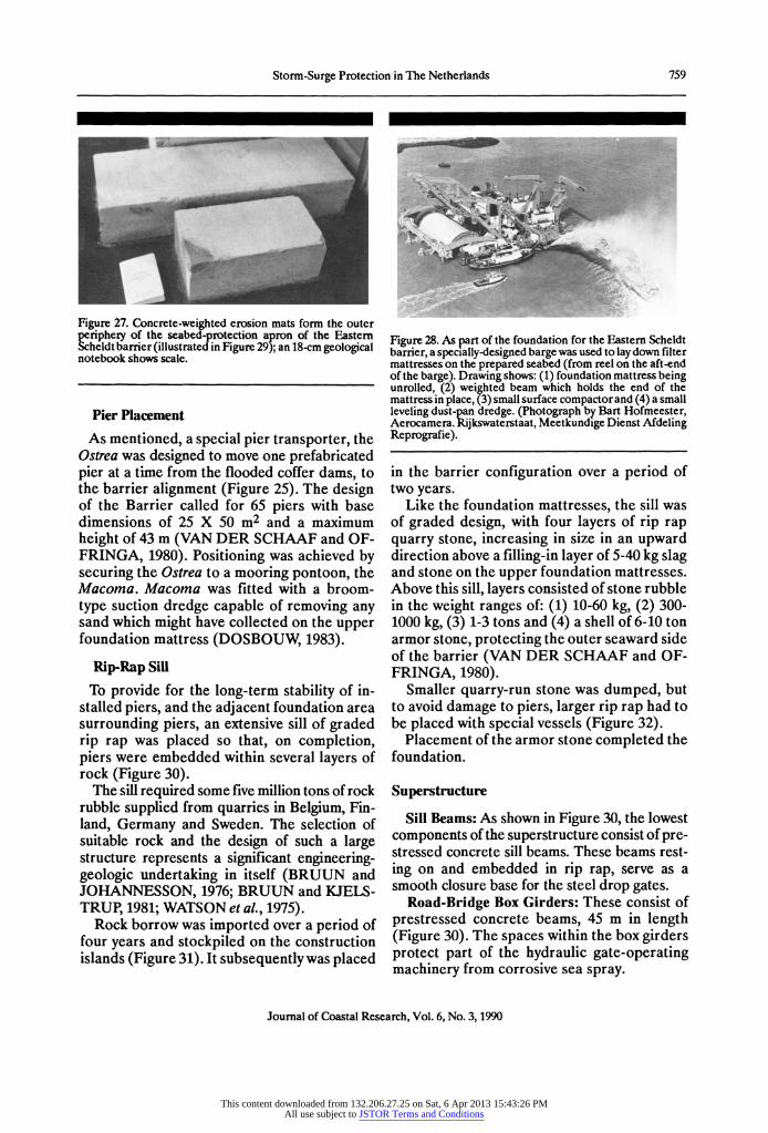
Figure 27. Concrete-weighted erosion mats form the outer riphery of the seabed-protection apron of the Eastern
Scheldt barrier (illustrated in Figure 29); an 18-cm geological notebook shows scale.
Pier Placement As mentioned, a special pier transporter, the
Ostrea was designed to move one prefabricated pier at a time from the flooded coffer dams, to the barrier alignment (Figure 25). The design of the Barrier called for 65 piers with base dimensions of 25 X 50 m2 and a maximum height of 43 m (VAN DER SCHAAF and OF- FRINGA, 1980). Positioning was achieved by securing the Ostrea to a mooring pontoon, the Macoma. Macoma was fitted with a broom- type suction dredge capable of removing any sand which might have collected on the upper foundation mattress (DOSBOUW, 1983).
Rip-Rap Sill
To provide for the long-term stability of in- stalled piers, and the adjacent foundation area surrounding piers, an extensive sill of graded rip rap was placed so that, on completion, piers were embedded within several layers of rock (Figure 30).
The sill required some five million tons of rock rubble supplied from quarries in Belgium, Fin- land, Germany and Sweden. The selection of suitable rock and the design of such a large structure represents a significant engineering- geologic undertaking in itself (BRUUN and JOHANNESSON, 1976; BRUUN and KJELS- TRUP, 1981; WATSON et al., 1975).
Rock borrow was imported over a period of four years and stockpiled on the construction islands (Figure 31). It subsequently was placed
Figure 28. As part of the foundation for the Eastern Scheldt barrier, a specially-designed barge was used to lay down filter mattresses on the prepared seabed (from reel on the aft-end of the barge). Drawing shows: (1) foundation mattress being unrolled, (2) weighted beam which holds the end of the mattress in place, (3) small surface compactor and (4) a small leveling dust-pan dredge. (Photograph by Bart Hofmeester, Aerocamera. Rijkswaterstaat, Meetkundige Dienst Afdeling Reprografie).
in the barrier configuration over a period of two years.
Like the foundation mattresses, the sill was of graded design, with four layers of rip rap quarry stone, increasing in size in an upward direction above a filling-in layer of 5-40 kg slag and stone on the upper foundation mattresses. Above this sill, layers consisted of stone rubble in the weight ranges of: (1) 10-60 kg, (2) 300- 1000 kg, (3) 1-3 tons and (4) a shell of 6-10 ton armor stone, protecting the outer seaward side of the barrier (VAN DER SCHAAF and OF- FRINGA, 1980).
Smaller quarry-run stone was dumped, but to avoid damage to piers, larger rip rap had to be placed with special vessels (Figure 32).
Placement of the armor stone completed the foundation.
Superstructure
Sill Beams: As shown in Figure 30, the lowest components of the superstructure consist of pre- stressed concrete sill beams. These beams rest- ing on and embedded in rip rap, serve as a smooth closure base for the steel drop gates.
Road-Bridge Box Girders: These consist of prestressed concrete beams, 45 m in length (Figure 30). The spaces within the box girders protect part of the hydraulic gate-operating machinery from corrosive sea spray.
Journal of Coastal Research, Vol. 6, No. 3, 1990
This content downloaded from 132.206.27.25 on Sat, 6 Apr 2013 15:43:26 PMAll use subject to JSTOR Terms and Conditions
760 Watson and Finkl
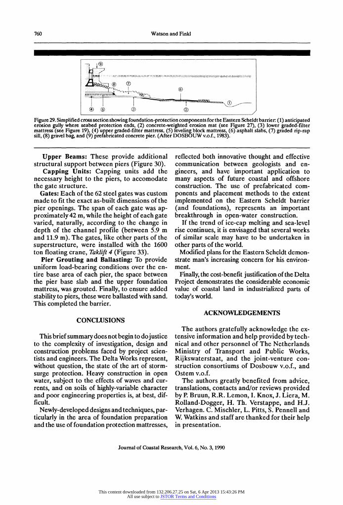
Figure 29. Simplified cross section showing foundation-protection components for the Eastern Scheldt barrier: (1) anticipated erosion gully where seabed protection ends, (2) concrete-weighted erosion mat (see Figure 27), (3) lower graded-filter mattress (see Figure 19), (4) upper graded-filter mattress, (5) leveling block mattress, (6) asphalt slabs, (7) graded rip-rap sill, (8) gravel bag, and (9) prefabricated concrete pier. (After DOSBOUW v.o.f., 1983).
Upper Beams: These provide additional structural support between piers (Figure 30).
Capping Units: Capping units add the necessary height to the piers, to accomodate the gate structure.
Gates: Each of the 62 steel gates was custom made to fit the exact as-built dimensions of the pier openings. The span of each gate was ap- proximately 42 m, while the height of each gate varied, naturally, according to the change in depth of the channel profile (between 5.9 m and 11.9 m). The gates, like other parts of the superstructure, were installed with the 1600 ton floating crane, Taklift 4 (Figure 33).
Pier Grouting and Ballasting: To provide uniform load-bearing conditions over the en- tire base area of each pier, the space between the pier base slab and the upper foundation mattress, was grouted. Finally, to ensure added stability to piers, these were ballasted with sand. This completed the barrier.
CONCLUSIONS
This brief summary does not begin to dojustice to the complexity of investigation, design and construction problems faced by project scien- tists and engineers. The Delta Works represent, without question, the state of the art of storm- surge protection. Heavy construction in open water, subject to the effects of waves and cur- rents, and on soils of highly-variable character and poor engineering properties is, at best, dif- ficult.
Newly-developed designs and techniques, par- ticularly in the area of foundation preparation and the use of foundation protection mattresses,
reflected both innovative thought and effective communication between geologists and en- gineers, and have important application to many aspects of future coastal and offshore construction. The use of prefabricated com- ponents and placement methods to the extent implemented on the Eastern Scheldt barrier (and foundations), represents an important breakthrough in open-water construction.
If the trend of ice-cap melting and sea-level rise continues, it is envisaged that several works of similar scale may have to be undertaken in other parts of the world.
Modified plans for the Eastern Scheldt demon- strate man's increasing concern for his environ- ment.
Finally, the cost-benefit justification of the Delta Project demonstrates the considerable economic value of coastal land in industrialized parts of today's world.
ACKNOWLEDGEMENTS
The authors gratefully acknowledge the ex- tensive information and help provided by tech- nical and other personnel of The Netherlands Ministry of Transport and Public Works, Rijkswaterstaat, and the joint-venture con- struction consortiums of Dosbouw v.o.f., and Ostem v.o.f.
The authors greatly benefited from advice, translations, contacts and/or reviews provided by P. Bruun, R.R. Lemon, I. Knox, J. Liera, M. Rolland-Dogger, H. Th. Verstappe, and H.J. Verhagen. C. Mischler, L. Pitts, S. Pennell and W. Watkins and staff are thanked for their help in presentation.
Journal of Coastal Research, Vol. 6, No. 3, 1990
This content downloaded from 132.206.27.25 on Sat, 6 Apr 2013 15:43:26 PMAll use subject to JSTOR Terms and Conditions

Storm-Surge Protection in The Netherlands 761
Figure 30. Foundation and structural components of the Eastern Scheldt barrier. (1) prefabricated gate-support pier, (2) rip-rap approach abutment, (3) support beam for gate-control equipment, (4) hydraulic cylinders for gate operation, (5) capping unit, (6) upper pier-connecting beam, (7) lift gate, (8) lower sill base, (9) road, (10) road box girders, (11) power supply and machinery for gate operation, (12) hollow, ballasted section for sill beam, (13) armor-stone, rip-rap protection for sill, (14) core-stone sill support, (15) sand-ballasted pier base, (16) sill-beam stops, (17) upper foundation mattress, (18) grouted section between mattress and pier base, (19) block mattress, (20) bottom mattress, (21) compacted-sand foundation bed, and (22) gravel bag. (After DOSBOUWv.o.f. (1983), drawing by Rudolf Das (1982), Rijkswaterstaat Meetkundige Dienst Afdeling Reprografie).
Journal of Coastal Research, Vol. 6, No. 3, 1990
This content downloaded from 132.206.27.25 on Sat, 6 Apr 2013 15:43:26 PMAll use subject to JSTOR Terms and Conditions

762 Watson and Finkl
Figure 31. Some five million tons of rock rip rap were im- ported from quarries in Belgium, Finland, Germany, and Sweden to pretect the foundations and lower sections of structural components of the Eastern Scheldt barrier. (Rijkswaterstaat Meetkundige Dienst Afdeling Reprografie).
Figure 32. Larger armorstone rip rap had to be placed by a special vessel to avoid damage to piers. (Photograph by Bart Hofmeester, Aerocamera, Rijkswaterstaat Meetkundige Dienst Afdeling Reprografie).
Research support was provided by Florida Atlantic
University and the Coastal Education and Research Foundation [CERF].
LITERATURE CITED
AMBRAYSEYS, N.N, and SARMA, S.KI, 1967. The Re-
Figure 33a. All large superstructure components of the East- ern Scheldt barrier were installed by the 1,600 ton floating Taklift 4. (Air photographs by Bart Hoffmeester, Aerocamera. Rijkswaterstaat Meetkundige Dienst Afdeling Reprografie). (a) installation of a gate.
Figure 33 cont. (b) Installation of a road-section box girder (Photograph shows the barrier across one of the three chan- nel sections of the Eastern Scheldt estuary).
sponse of Earth Dams to Strong Earthquakes. Geotechni- que, 17, (3), 181-213.
ANTONISSE, R, 1986. De kroon op het Deltaplan. Stormvloed- kering Oosterschelde. Het grootste waterbouwproject aller tij- den MCMLXXX7V. Elsevier Boeken B.V., Amsterdam/Brussel, 224p.
BJERRUM, L., 1973. Geotechnical Problems Involved in Foundations of Structures in the North Sea. Geotechnique, 23, (3), 319-358.
BOEHMER, J.W., 1978. Geotechnical Oosterschelde Studies and Some Unexpected Aspects. In: Foundation As- pects of Coastal Structures. Vol. 1, International Symposium on Soil Mechanics Research and Foundation Design for the Oosterschelde Storm Surge Barrier. Delft, The Nether- lands, 1.3, 1-16.
Journal of Coastal Research, Vol. 6, No. 3, 1990
This content downloaded from 132.206.27.25 on Sat, 6 Apr 2013 15:43:26 PMAll use subject to JSTOR Terms and Conditions

Storm-Surge Protection in The Netherlands 763
Figure 33 cont. (c) A close-up of the pier-supported, lift-gate sections of the barrier.
BRUUN, P., and JOHANNESSON, P., 1976. Parameters Affecting Stability of Rubble Mounds. Journal Waterways, Harbors and Coastal Engineering, Vol. 102, WW2.
BRUUN, P., and KJELSTRUP, S., 1981. Practical Views on the Design and Construction of Mound Breakwaters. Coas- tal Engineering, 5.
de JONG, DJ.; LEEWIS, R.J.; MISDORP, R; STORTEL- DER, P.B.M., and VISSER, J., 1987. Ecological Conditions. In: van Aalst, W. (Ed. Co-ordinator), The Closure of Tidal Basins. Delft University Press, The Netherlands, pp. 115-134.
de LEEUW, E.H., 1976. Results of Large Scale Liquefaction Tests. International Conference on Behaviour of Offshore Structures, Boss '76, Trondheim, Vol. 11, 65-84.
de MULDER, E.FJ., and van RUMMELEN, F.F.F.E., 1978. Engineering Geology: Construction of a Stratigraphic Model. In: Foundation Aspects of Coastal Structures. Vol. 2. Interna- tional Symposium on Soil Mechanics Research and Founda- tion Design for the Oosterschelde Storm Surge Barrier. Delft, The Netherlands, V.lb, 1-14.
DOSBOUW v.o.f., 1983. The Storm Surge Barrier in the East- ern Scheldt, for Safety and the Environment. A joint publica- tion by the Oosterschelde Stormvloedkring Bouwcombanie (DOSBOUW) v. o.f. and Voorlichting Verkeer en Waterstaat, 32p.
ENGEL, H., 1980. Overall Picture of the Project. In: Hydraulic Aspect of Coastal Structures. Part 1. Developments in Hydraulic Engineering related to the design of the Oosterschelde Storm Surge Barrier in the Netherlands. Delft University Press, The Netherlands, pp. 3-16.
ENGEL, H., 1987. Perface. In: van Aalst, W. (Ed. Co-or- dinator). The Closure of Tidal Basins. Delft University Press. The Netherlands, 743p.
HUIS in 't VELD, J.C., 1987a. Gradual Closures. In: van Aalst, W. (Ed. Co-ordinator), The Closure of Tidal Basins. Delft University Press, The Netherlands, pp. 601-609.
HUIS, in 't VELD, J.C., 1987b. Sudden Closure. In: van Aalst, W. (Ed. Co-ordinator), The Closure of lidal Basins.
Delft University Press, The Netherlands, pp. 627-639.
NIEUWENHUIS, J.K., 1987a. Stability and Deformation of Closure Foundations. In: van Aalst, W. (Editorial Co-or- dinator), The Closure of Tidal Basins, Delft University Press, The Netherlands, 319-341.
NIEUWENHUIS, J.K., 1987b. Earthquake Induced Loads. In: van Aalst, W. (Ed. Co-ordinator), The Closure of Tidal Basins. Delft University Press, The Netherlands, pp. 307- 318.
PILARCZYK, KW., 1987a. Ice Induced Loads. In: van Aalst, W. (Ed. Co-ordinator), The Closure of Tidal Basins. Delft University Press. The Netherlands, pp. 295-305.
PILARCZYK, KIW., 1987b. Local Scour. In: van Aalst, W. (Ed. Co-ordinator), The Closure of Tidal Basins. Delft University Press, The Netherlands, pp. 387-405.
PILARCZYK, K.W., 1987c Filters. In: van Aalst, W. (Ed. Co-ordinator), The Closure ofTidal Basins. Delft University Press, The Netherlands, pp. 467-489.
RIJKSWATERSTAAT,1987. The Compartmentalization Works in the Eastern Scheldt for the Benefit of the Natural Environment, Water Management and Shipping. Dutch Government Printing Office, 2nd Impression, 32p.
SCHELLEKENS, J.P.; WOUTERS, J., and VRIJLING, J.K., 1980. Transition Structures between Barrier and Dikes. In: Hydraulic Aspects of Coastal Structures, Part 2: Developments in Hydraulic Engineering. Delft University Press, pp. 121-139.
SEED, H.B., 1979. Considerations in the Earthquake-Resis- tant Design of Earth and Rockfill Dams, Geotechnique, 29, (3), 215-263.
SMITS, F.P.; ANDERSEN, K.H., and GUDEHUS, G., 1978. Pore Pressure Generation. In: Foundation Aspects of Coas- tal Structures. Vol. 1. International Symposium on Soil Mechanics Research and Foundation Design for the Oosterschelde Storm Surge Barrier. Delft, The Nether- lands, 11.3, 1-16.
van AALST, W., and BRUINSMA, J., 1987. Waves. In: van Aalst, W., (Ed. Co-ordinator), The Closure of Tidal Basins. Delft University Press, The Netherlands, pp. 53-71.
v.d. BURG, J.C., and NIEUWENHUIS, J.K., 1987. Groundwater Flow. In: van Aalst, W. (Ed. Co-ordinator), The Closure of Tidal Basins. Delft University Press, The Netherlands, pp. 447-466.
van de REE, W., and STUIP, J., 1987. Measurement of Currents. In: van Aalst W., (Ed. Co-ordinator). The Clos- ure of Tidal basins, Delft University Press, The Nether- lands, 147-168.
van der SCHAAF, T. and OFFRINGA, G., 1980. Outline of Construction Methods. In: Hydraulic aspects of Coastal Structures. Part 2. Developments in Hydraulic Engineering related to the design of the Oosterschelde Storm Surge Barrier in the Netherlands. Delft University Press, 141-171.
van WESTERN, J.M., 1987. Closure of the Brouwer- shavensche gat by the construction of the Brouwers Dam. In: van Aalst, W. (Ed. Co-ordinator), The Closure of Tidal Basins, Delft University Press, The Netherlands, pp. 665- 727.
VERMEIDEN, J. and LUBKING, P., 1978. Soil Investigation. In: Foundation Aspects of Coastal Structures. Proceedings
Journal of Coastal Research, Vol. 6, No. 3, 1990
This content downloaded from 132.206.27.25 on Sat, 6 Apr 2013 15:43:26 PMAll use subject to JSTOR Terms and Conditions

764 Watson and Finkl
Vol. 2. International Symposinum on Soil Mechanics Research and Foundation Design for the Oosterschelde Storm Surge Barrier. Delft, The Netherlands, V.IA, 1-32.
VRIJLING, J.K., and BRUINSMA, J. 1980. Hydraulic Bound- ary Conditions. In: Hydrauic Aspects of Coastal Structures, Part 1. Developments in Hydraulic Engineering related to the design of the Oosterschelde Storm Surge Barrier in the Netherlands. Delft University Press, The Netherlands, pp. 109-133.
WALTHER, A.W., 1987. Introduction. In: van Aalst, W. (Ed. Co-ordinator), The Closure of7idal Basins. Delft University Press, The Netherlands, pp. 9-14.
WATSON, I.; FISCHER, J.A., and URLICH, C.M., 1975. Geotechnical aspects of rock borrow for large breakwaters. 7th Annual Ofshore Technology Conference, Texas. OTC 2392, Vol. 111, 553-563.
WATSON, I., and KRUPA, S., 1984. Marine drilling explora- tion, technical and environmental criteria for rig selection. Litoralia, 1(1), 65-81.
WEENINK, M.P.H., 1958. A theory and method of calcula- tion of wind effects on sea levels in a partly enclosed sea with special application to the southern coast of the North Sea. KNMI, Med. en Verh., No. 73, 27p.
O ZUSAMMENFASSUNG 0 Ein Multi-Milliarden-Dollar-Komplex von Kiistenbauwerken schiitzt die Delta- und Astuar-Regionen der suidwest- lichen Niederlande vor der Wiederholung der Sturmflutereignisse von 1953, bei denen 1835 Menschen ums Leben kamen. Insgesamt sind seit 1717 8 grosse Sturm-flutkatastrophen beleget. Das Deltaprojekt gewiihrt bereits seit 1986 vollen Sturmflutschutz, obwohl immer noch Teile davon unvollendet sind. Als eines der gr6ssten zivilen Bauprojekete der Erder haben seine 11 Haupt- und zahlreichen Nebenabschnitte die Aufgabe (1) drei Hauptistaure abzuschneiden und damit die Kiistenlinien um ca. 720 km zu verkiirzen, (2) als Verbindung zwischen Schelde und Rhein einen gezeitenfreien Wasserweg zu schaffen, der die Schiffahrt zwischen Antwerpen und Rotterdam (120 km), zwei der grossten Hiifen der Welt, erleichtert, und (3) Teile der Deltafliche zu schiitzen. Diese Fallstudie beschreibt die geologischen und Fundamentierungs-probleme, die Planung und den Bau, die Vor- untersuchungen und Vorbereitungen der Fundamente, die Methoden der Konstruktion und die Wechselwirkung zwischen Untergrund und Aufbauten. Hauptgegenstand ist die reisige Kontrollbarriere von 7,5 km Liinge, welche 1986 die 6stliche Scheldemiindung abschloss und die bei weitem der schwierigste und teuerste Bauabschnitt war. Hier und in anderen Teilen des Deltas haben die mangelnde Erfahrung mit solchen Bauwerken, die komplexe lokale Geologie und die starken Gezeitenstr6mungen dazu gefuihrt, dass allein die Fundamentierung 80% der gesamten Bauzeit in Anspruch nahm. Die dabei neu entwickelten Techniken werden in Zukunft weltweit bei Kiisten- und Seebauwerken verwendt werden. - Dieter Kelletat, Essen, FRG.
0 RESUMe O C'est un complexe de constructions c6tieres coOtant plusieurs billions de dollards qui protege la Hollande d'une rip6tition de la catastrophe de 1953 qui fit 1835 morts. Depuis 1717 huit invasions de la mer avaient &t6 enregistrdes. Le projet de Delta ne protege efficacement le pays de l'inondation que depuis 1986, mais certaines sections sont encore en construction. Ce projet d'ing6nierie civile ets un des plus vastes du monde. II a onze composantes majeures et de multiples autres, secondaires. Leur fonction et de: (1) fermer les principaux estuaires, ce qui raccourcit la ligne de rivage A 720 km; (2) crder un acces non soumis a la marie au "Scheldt-Rhein" pour faciliter l'acces aux navires d'Anvers a Rotterdam (120 km), deux des plus importants ports du monde et (3) assurer une prdservation partielle de l'environment du delta. Cette historie de cas concerne la gdologie et les problemes de fondations, la planification et les sequences de construction, la recherche sur le site et la prdparation des fondations, les methodes de construction et l'interaction fondations-structures. Le point cl est la digue-barriere de protection a grande echelle terminde en 1986, traversant sur 7,5 km l'estuaire de Scheldt de 'Est qui constitue de loin la partie la plus difficile et la plus co teuse du projet. Ici comme dans d'autres parties du delta, les forts courants de marie et la grande variabilitd des materiaux geologiques peu appropri6s aux construction d'ouvrages ont fait que 80% du temps de la construction ont dtd n6cessaires a l'establissement des seules fondations. Les nouvelles techniques qui ont dtd
ddvelopples pour le projet ont une application A l'6chelle mondiale pour les futures constructions c6tidres et offshore. - Catherine Bressolier, Geomorphologie EPHE, Montrouge, France.
88040 received 7 February 1989; accepted in revision 5 January 1990. To be published in Dutch and English in 1991 as Special Issue No. 10.
This content downloaded from 132.206.27.25 on Sat, 6 Apr 2013 15:43:26 PMAll use subject to JSTOR Terms and Conditions