co2 capture from igcc gas streams using the ac … library/events/2014/2014 netl co2...2 capture...
TRANSCRIPT

CO2 Capture from IGCC Gas Streams Using the AC-ABC Process
2014 NETL CO2 Capture Technology Meeting July 31, 2014 Pittsburgh, PA.
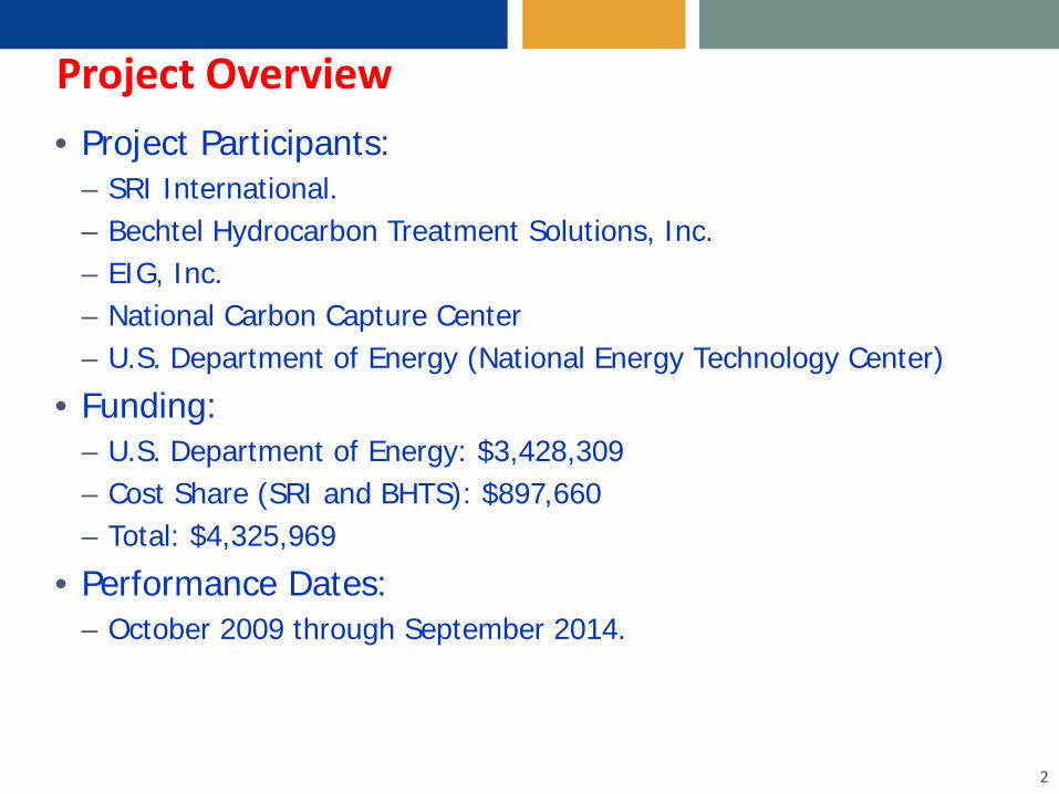
Project Overview • Project Participants:
– SRI International. – Bechtel Hydrocarbon Treatment Solutions, Inc. – EIG, Inc. – National Carbon Capture Center – U.S. Department of Energy (National Energy Technology Center)
• Funding: – U.S. Department of Energy: $3,428,309 – Cost Share (SRI and BHTS): $897,660 – Total: $4,325,969
• Performance Dates: – October 2009 through September 2014.
2

Project Objectives
• Overall objective: – To develop an innovative, low-cost CO2 capture technology based on
absorption on a high-capacity and low-cost aqueous ammoniated solution with high pressure absorber and stripper.
• Specific objectives and project status: – Test the concept on a bench scale batch reactor (completed) – Determine the preliminary optimum operating conditions (completed) – Design and build a small pilot-scale reactor capable of continuous
integrated operation (Design completed; Equipment procurement and assembly in progress, Hazop analysis completed).
– Perform tests to evaluate the process in a coal gasifier environment (in progress)
– Perform a technical and economic evaluation on the technology (Updates are in progress).
3

Process Fundamentals • Uses well-known reaction between carbon dioxide and
aqueous ammonia : • Reactions are reversible
– Absorption reactions at lower temperature – Desorption reactions at higher temperature
• High pressure operation enhances absorption of CO2. • A similar set of reactions occur between H2S and
ammoniated solution. • H2S from the regenerated gas is converted to elemental
sulfur at high pressures.
4
NH4OH+CO2 NH4HCO3 (NH4) 2CO3+CO2 + H2O 2NH4HCO3 NH4 (NH2CO2)+CO2+2H2O 2NH4HCO3

Process Block Flow Diagram
5

Process Highlights • Concentrated ammoniated solution is used to capture
both CO2 and H2S from syngas at high pressure. • Absorber operation at 40o-60o C temperature; No
refrigeration is needed. • CO2 is released at high pressures (30 bar) at <200°C:
– The size of CO2 stripper, the number of stages of CO2 compression, and the electric power for compression of CO2 to the pipeline pressure are reduced.
• High net CO2 loading, up to 20% by weight. • The stripper off-gas stream, containing primarily CO2 and
H2S, is treated using a high pressure Claus process, invented by Bechtel, to form elemental sulfur. – CO2 is retained at high pressures.
6

Process Advantages • Low cost and readily available reagent (aqueous ammonia). • Reagent is chemically stable under the operating conditions.
– Ammonia does not decompose under the operating conditions.
• High efficiency for CO2 capture – Reduces water-gas shift requirements - Reduced steam consumption.
• No loss of CO2 during sulfur recovery – High pressure conversion; No tail gas treatment
• Low heat consumption for CO2 stripping (<600 Btu/lb CO2). • Extremely low solubility of H2, CO and CH4 in absorber
solution: Minimizes losses of fuel species. • Absorber and regenerator can operate at similar pressure.
– No need to pump solution cross pressure boundaries. Low energy consumption for pumping.
7

CO2 Capture Efficiency vs Solution Composition
8
0
10
20
30
40
50
60
70
80
90
100
0.40 0.45 0.50 0.55 0.60 0.65 0.70 0.75 0.80
Cap
ture
Effi
cien
cy (%
)
R' (Molar Ratio, CO2/NH3)
Run 17 (4 M, 50 C)
Run 16 (4 M, 33 C)
Run 18 (4 M, 45 C)
Run 19 (4 M, 60 C)
Run 20 (4 M, 43 C)
Run 21 (8 M, 55 C)
Inlet CO2 Partial Pressure 450 kPa
8 M, 55 C4 M, 60 C
4 M, 43 C
Reactor Volume = 0.0045 m3
Reactor Pressue = 265 psia
CO2 Capture Efficiency Exceeds 90%

Rapid Rate of Reactions Approaching Equilibrium
9
0
10
20
30
40
50
0.1 0.2 0.3 0.4 0.5 0.6 0.7
CO
2Pa
rtial
Pre
ssur
e at
the
Exit
(psi
a)
R', Molar Ratio CO2/NH3
Run 17 (4 M, 50 C)
Run 16 (4 M, 33 C)
Run 13 (4 M, 45 C)
Run 11 (4 M, 45 C)
Run 18 (4 M, 45 C)
Run 19 (4 M, 60 C)
Run 20 (4 M, 43 C)
Run 21 (8 M, 55 C)
Equilibrium Line (10 M, 55 C)
Absorber Operating Pressure = 1800 kPa (265 psia)4 M and 8M Ammonia, 0.88 acfm CO2 flow rate (25 %v/v)

High Efficiency of H2S Capture
10
Target < 1 ppm H2S
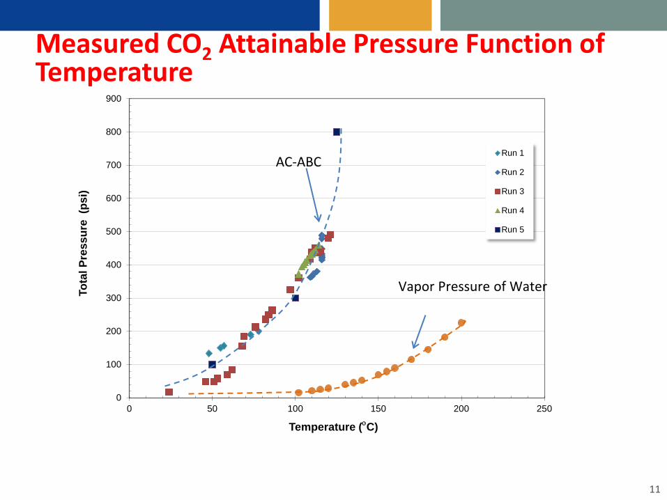
Measured CO2 Attainable Pressure Function of Temperature
11
0
100
200
300
400
500
600
700
800
900
0 50 100 150 200 250
Tota
l Pre
ssur
e (p
si)
Temperature (οC)
Run 1
Run 2
Run 3
Run 4
Run 5
Vapor Pressure of Water
AC-ABC

AC-ABC Process Schematic
12
Sour water
Clean Syngas
Syngas Feed Steam
Shift 1
Boiler Feed water
To BPSC
Steam
Shift 2
CO2/H2SStripper
dP=10-20psi
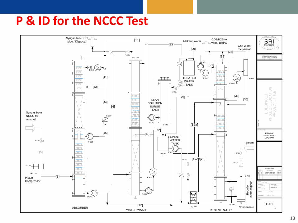
P & ID for the NCCC Test
13
E-700
Syngas to NCCC pipe / Disposal
Steam
CO2/H2S to vent / BHPC
F
FE-721
Condensate
K-150
E-720
[33][35]
[34]
[32]
Gas Water Separator
Reb
oile
rTh
erm
osip
hon
[45]
[41]
[4]
Piston Compressor
TI711
[42]
G-721
V-700
Syngas from NCCC tar removal
OF
DATE:
SHEET
DRAWING TITLE
JOB NO:
APPROVED BY:
DESIGNED BY:DRAWN BY:
SCALE:
PRO
JEC
T TI
TLE
CHARGE NO:
333 RAVENSWOOD AVE.MENLO PARK, CA 94025
REVISION LOG
# DATEBY DESCRIPTION
PIPING & INSTRUMENT
DIAGRAM
P-01
A AN ISSUED FOR REVIEW 08-14-12
ABSORBERREGENERATOR
SRIR
International
V-900
E-320
E-340
E-900
SSV-152
[3] E-500
PV-521[5]
[12]
[12c]/[25]
[12a]
FE-501
V-600
[11]
WATER WASH
LEANSOLUTION
SURGE TANK
V-620
[73]
P-621
[23]
SPENTWATERTANK
P-641
V-640
TREATEDWATERTANK
[21]
[22]
[24]
S
NY-611
S
NY-612
[1]
Air
P-651
P-601
P-501P-301
P-321
ISSUED FOR REVIEWB AN 03-28-13
[72]
[44]
[43]
[20]
Makeup water
[46]
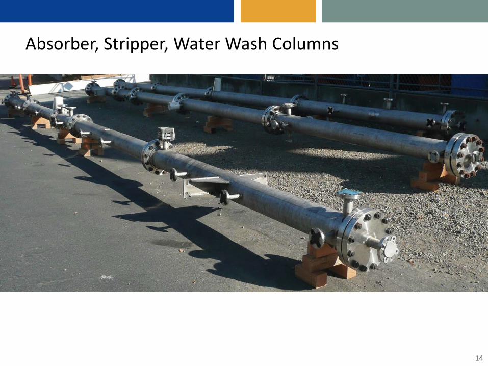
Absorber, Stripper, Water Wash Columns
14
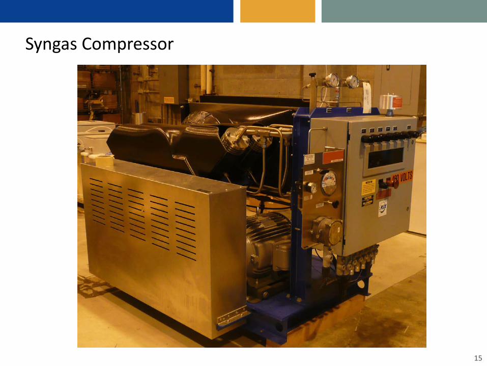
Syngas Compressor
15

Heat Exchangers and Circulating Pumps
16
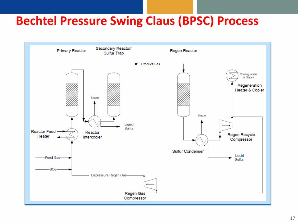
Bechtel Pressure Swing Claus (BPSC) Process
17
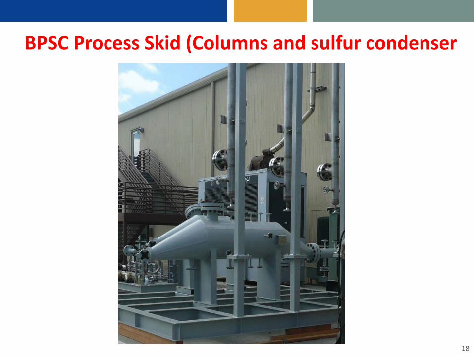
BPSC Process Skid (Columns and sulfur condenser
18

AC-ABC and BPSC Process Changes to IGCC Reference Case
19
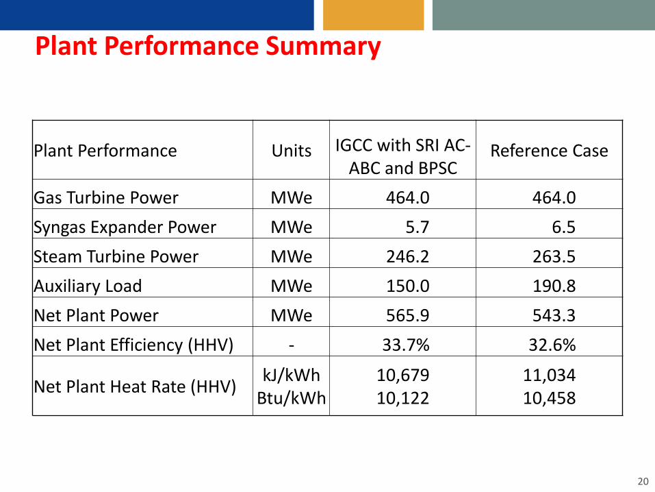
Plant Performance Summary
20
Plant Performance Units IGCC with SRI AC-ABC and BPSC
Reference Case
Gas Turbine Power MWe 464.0 464.0 Syngas Expander Power MWe 5.7 6.5 Steam Turbine Power MWe 246.2 263.5 Auxiliary Load MWe 150.0 190.8 Net Plant Power MWe 565.9 543.3 Net Plant Efficiency (HHV) - 33.7% 32.6%
Net Plant Heat Rate (HHV) kJ/kWh Btu/kWh
10,679 10,122
11,034 10,458
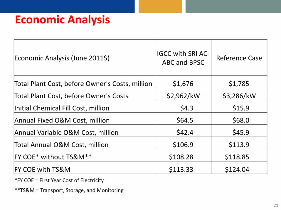
Economic Analysis
21
Economic Analysis (June 2011$) IGCC with SRI AC-ABC and BPSC Reference Case
Total Plant Cost, before Owner's Costs, million $1,676 $1,785
Total Plant Cost, before Owner's Costs $2,962/kW $3,286/kW
Initial Chemical Fill Cost, million $4.3 $15.9
Annual Fixed O&M Cost, million $64.5 $68.0
Annual Variable O&M Cost, million $42.4 $45.9
Total Annual O&M Cost, million $106.9 $113.9
FY COE* without TS&M** $108.28 $118.85
FY COE with TS&M $113.33 $124.04 *FY COE = First Year Cost of Electricity
**TS&M = Transport, Storage, and Monitoring

Anticipated Benefits, if Successful
• We estimate a 22.7 MW improvement in Net Plant Power and a 1.1 percentage point increase in Net Plant Efficiency (HHV basis) than a reference plant (GE gasifier with Selexol AGR and conventional Claus).
• Capital cost is ~6% less expensive than the reference plant on an absolute basis and 9% less on a normalized basis.
• The COE is 9% lower for the SRI AC-ABC and BPSC plant relative to the reference case.
• The process configuration is economically viable per this analysis.
• The process will be tested in this Budget Period at the National Carbon Capture Center.
22

Acknowledgement • SRI International
– Gopala Krishnan, Indira Jayaweera, Anoop Nagar, Srini Bhamidi, Jianer Bao
• EIG: Eli Gal • Bechtel Hydrocarbon Treatment Solutions:
– Lee Schmoe and Martin Taylor • National Carbon Capture Center: Frank Morton and Tony Wu • DOE-NETL
– Elaine Everett, Megan Napoli, Susan Maley, Lynn Brickett, Jenny Tennent, John Lytenski, Michael Matuszewski, James Black, Peter Kabateck.
23

DISCLAIMER This presentation was prepared as an account of work sponsored by an agency of the
United States Government. Neither the United States Government nor any agency
thereof, nor any of their employees, makes any warranty, express or implied, or assumes
any legal liability or responsibility for the accuracy, completeness, or usefulness of any
information, apparatus, product, or process disclosed, or represents that its use would
not infringe privately owned rights. Reference herein to any specific commercial product,
process, or service by trade name, trademark, manufacturer, or otherwise does not
necessarily constitute or imply endorsement, recommendation, or favoring by the United
States Government or any agency thereof. The views and opinions of authors expressed
herein do not necessarily state or reflect those of the United States Government or any
agency thereof.
24

Headquarters: Silicon Valley SRI International 333 Ravenswood Avenue Menlo Park, CA 94025-3493 650.859.2000 Washington, D.C.
SRI International 1100 Wilson Blvd., Suite 2800 Arlington, VA 22209-3915 703.524.2053 Princeton, New Jersey
SRI International Sarnoff 201 Washington Road Princeton, NJ 08540 609.734.2553 Additional U.S. and international locations www.sri.com
Thank You