co-injection resin transfer molding of vinyl-ester and ... · arl-tr-2150 january 2000 20000217 022...
TRANSCRIPT

ARMY RESEARCH LABORATORY
Co-Injection Resin Transfer Molding of Vinyl-Ester and Phenolic Composites
by Bruce K. Fink, Emanuele F. Gillio, Geoffrey P. McKnight, John W. Gillespie Jr.,
Suresh G. Advani, Rushad F. Eduljee, and Karl R. Bemetich
ARL-TR-2150 January 2000
20000217 022 Approved for public release; distribution is unlimited.
JUTIC QUÄLEST W&i&^iäjj l

Tne findings in this report are not to be construed as an official Department of the Army position unless so designated by other authorized documents.
Citation of manufacturer's or trade names does not constitute an official endorsement or approval of the use thereof.
Destroy this report when it is no longer needed. Do not return it to the originator.

Abstract .
Vacuum-assisted resin transfer molding (VARTM)-type processes have been proven cost-effective manufacturing techniques for large composite structures. However, their use has been limited to a single resin system. Many composite structures require multiple resins to serve different purposes while being integrated into a single structure. Co-injection resin transfer molding (CIRTM) is a new manufacturing process developed by the U.S. Army Research Laboratory (ARL) with the University of Delaware that enables the user to manufacture multilayer hybrid composite parts in a single processing step. In this report, CIRTM is used to manufacture a dual-layered structure consisting of a vinyl-ester layer for structural integrity and a phenolic layer for fire, smoke, and toxicity protection. The two resins are simultaneously injected into a mold filled with a stationary fiber bed and are co-cured. Resin separation is maintained by a 1-mil-thick polysulfone film sandwiched between two layers of 6.5-mil-thick adhesive. A differential scanning calorimeter (DSC) is used to select the optimum cure cycle for all of the materials. Mechanical testing is used to evaluate the performance of the interphase formed between dissimilar materials. Experimental results show that co-injected, co-cured materials offer equivalent properties, or, in some cases, more superior properties than those provided by single-injection resin composites. This case is used to develop and present a methodology that can be followed to co-inject different resins.
u

Acknowledgments
The authors acknowledge the funding support provided from the U.S. Army Research Laboratory
(ARL) to establish the Composite Materials Research Program at the University of Delaware.
in

INTENTIONALLY LEFT BLANK.
IV

Table of Contents
Page
Acknowledgments iii
List of Figures vii
List of Tables •• vii
1. Background and Motivation 1
2. Manufacturing Procedure 2
2.1 Processing 2 2.2 Materials 5
3. Results and Discussion 7
3.1 Short Beam Shear 7 3.2 DCB Testing 8 3.3 Durability Tests 13
4. Conclusions 13
5. References 15
Distribution List 17
Report Documentation Page 25

INTENTIONALLY LEFT BLANK.
VI

List of Figures
Figure Page
1. Experimental Setup Used to Manufacture the Co-Injected Specimens 3
2. Degree of Cure of the Epoxy Adhesive at Different Temperatures 6
3. Typical Mode I Fracture Toughness vs. Crack Length 10
4. Crack Opening Displacement Rate vs. Crack Length 12
5. Fracture Toughness vs. Crack Length for Co-Injected Specimens Tested at Different Crosshead Speeds 12
6. Crack Length vs. Time for All Materials Tested 14
List of Tables
Table Page
1. Short Beam Shear Results 8
2. Summary of DCB Results 10
vn

INTENTIONALLY LEFT BLANK.
vm

1. Background and Motivation
Composite materials have a number of advantages over traditional materials. Some of these
advantages are light weight, high stiffness-to-weight ratio, improved signature management, and
resistance to corrosion. In most cases, one material cannot serve all of these functions, but different
materials can be easily layered to serve multiple tasks while being integrated in a single structure.
For example, vinyl esters are low-cost resins that offer good mechanical properties, room-
temperature cure, and reliable processing. However, they are extremely flammable and produce
toxic smoke upon combustion. This limits their use in a variety of applications where material
flammability is a concern. Phenolic resins offer low cost but poor mechanical properties due to the
evolution of water during cure. However, they offer outstanding fire, smoke, and toxicity protection
[1]. Using co-injection resin transfer molding (CIRTM) [2], a single structure can be manufactured
with a thick layer of vinyl ester to take advantage of its mechanical properties and a thin layer of
phenolic to act as a fire, smoke, and toxicity barrier.
Pike, McArthur, and Schade [3] have shown that vacuum-assisted resin transfer molding
(VARTM) processes are cost-effective methods to manufacture large structures. CIRTM takes
advantage of these methods and improves them by enabling them to manufacture multilayer
structures in a single processing step. Prior to CIRTM, each layer would typically be manufactured
individually and then bonded together. This approach requires multiple steps, including surface
pretreatments and adhesive bonding, which can introduce additional defects into the part. CIRTM
eliminates all of these additional steps, lowers costs, and can improve quality and performance of
the part due to the co-cure feature of the process. The fundamentals of CIRTM are investigated in
detail by Gillio [4] and by Gillio et al. [5]. In this present study, the CIRTM process is described and
used to fabricate glass-reinforced vinyl-ester/phenolic hybrid composites. Parts are subject to a
variety of tests to characterize mechanical properties and durability of the interphase formed during
co-injection and co-cure.

2. Manufacturing Procedure
2.1 Processing. In the vast majority of structural applications, the vinyl-ester layer would be
considerably thicker than the phenolic layer. However, in this research, the co-injected preforms
were of equal thickness. This was done because the mechanical tests performed to evaluate the
interphase properties require that the interface between the dissimilar materials be located at the
geometric midplane. Additionally, the Mode I mterlaminar fracture double cantilever beam (DCB)
test and the wedge test require that the precrack be placed at the midthickness between two cantilever
beams of comparable stiffness. Therefore, under the assumption that the modulus is a fiber-
dominated property, the panels were manufactured with the same fiber reinforcement throughout the
thickness. Sublaminates infiltrated with each type of resin were assumed to have the same modulus.
Figure 1 shows the experimental setup used to manufacture the co-injected specimens. Seven
layers of S2-glass twill-weave, 18-oz/yd2 fabric were used for the phenolic and vinyl-ester preforms.
The vinyl ester used in this study was Dow Derakane 411-350, which is a room-temperature vinyl
ester with a gel time of approximately 30 min. The phenolic used was J2027/L manufactured by
British Petroleum and cures at approximately 140° F. An impermeable separation layer was used
between them to demonstrate the feasibility of this method for large composite structures. The need
for an impermeable separation layer was investigated by Gillio et al. [6]. The setup used in this
study is typical of the Seemann composite resin infusion molding process (SCRIMP) [7]. The
distribution medium placed on each side of the preforms is a high-permeability material that helps
carry the flow along the length and width of the part while the resin flows through the thickness of
the preform. The distribution media drastically reduces fill times and enables thick section parts to
be impregnated under vacuum only. The resins were simultaneously injected from the two injection
locations shown in the figure. Once the part was infused and the resin had cured, the distribution
medium was removed.

phenolic J2027
vinyl ester 411-350
flow direction
mold surface
vacuum line
distribution media
separation layer
vacuum bag
release ply
window
mold surface
S-glass preforms
release ply
distribution media
Figure 1. Experimental Setup Used to Manufacture the Co-Injected Specimens.
The impermeable separation layer was formed of a polysulfone film sandwiched between two
layers of epoxy-based adhesive. This solution exploits the diffusion-enhanced adhesion (DEA)
[8-10] mechanisms where epoxy and the amine curing agent diffuse and react in the polysulfone
barrier layer. A 1-mil-thick polysulfone film was selected to go into solution quickly with the epoxy
and to toughen the interphase during cure. Additionally, the phenolic is co-cured with the

compatible epoxy. The approach provides a toughened co-cured interphase between materials that
would not be compatible otherwise.
The manufacturing took place in the following steps. First, the mold surface, a flat steel plate,
was cleaned and mold release was applied to it. Then, the distribution medium was placed on the
plate. On top of it, an impermeable layer was placed in which a window had been cut approximately
1 in smaller than the preform on each side. The purpose of this window was only to avoid edge
effects, and it was removed, together with the distribution media, after the process was complete. A
layer of release film was placed on top of these two layers so that they could be removed. The first
seven layers of S2-glass were then placed on top of the release film so that the distribution media
would extend out from underneath the preform on one side. Then, the separation layer was placed
on top of the fiber preform. Generally, the polysulfone film was sandwiched between the epoxy
adhesive before the part was laid up. Once the separation layer was in place, seven layers of S2-glass
were placed on top of the preform followed by another layer of release ply and a layer of distribution
media. At this point, the lay-up was complete. Two inlet tubes were used. One was placed on top
of the preform, and the second one on the part of the bottom distribution media that extended out
from underneath the preform. The vacuum tube was placed at the opposite end of the preforms.
This whole assembly was then placed under a vacuum bag and sealed, and the vacuum was applied.
The vacuum serves three purposes: (1) it compacts the fabric; (2) it removes the air, thus reducing
the number of voids in the composite; and (3) it creates a pressure difference that drives the
impregnation of the resin into the spaces between the fibers.
A number of baseline panels were manufactured and tested, and the results from all specimens
were compared. Two single-resin baseline panels were manufactured: one with a vinyl-ester matrix
and one with a phenolic matrix. The main purpose of these baselines was to assess the performance
of the co-injected parts. It would not be expected that the co-injected specimens would perform
better than the weaker of the two constituent materials. Finally, a panel was manufactured in a three-
step process to simulate the current multistep procedure used to manufacture multilayer structures.
Two panels were manufactured: one using phenolic and the other using vinyl-ester resins. Then,

they were bonded together using the same adhesive film used in co-injection. In order to limit the
number of variables, the polysulfone film was used together with the adhesive in an effort to
compare manufacturing techniques.
2.2 Materials. One of the primary challenges presented by co-injection is the selection of a cure
cycle. During co-injection, two or more polymers co-cure together. Therefore a cure cycle must be
selected, which allows the successful cure of all polymers. Since this application of CIRTM is
designed for large structures, the goal in selecting the materials was to maintain the cure cycle below
200° F (95° C). The vinyl ester used was Dow Derakane 411-350, which cures at room temperature
using 0.2% by weight of cobalt napthenate as the accelerator and 2% by weight of Trigonox 239A
(organic peroxide) as the initiator. The phenolic was British Petroleum's J2027/L, a low-viscosity
resole phenolic that was catalyzed using 5% by weight Phencat 381. This phenolic must be cured
at approximately 140° F in order to limit void formation due to the water present in the phenolic
resin. Two adhesive films were selected for this study. The first was 3M's AF-163-20ST, which
is an amine-cured epoxy-based adhesive. This adhesive is designed to cure at 225° F or higher.
However, Figure 2 shows that it is possible to cure it as low as 200° F if the time periods are
extended significantly. Another adhesive, a phenolic-epoxy (PH/EP), was selected due to its better
compatibility between the adhesive and the bulk phenolic. This resin is manufactured by
Cytec-Fiberite as a film adhesive, HT 424. The compatibility is believed to be improved with this
adhesive because PH/EP has a similar curing reaction to the bulk phenolic resin, whereas the epoxy
adhesive has a much different curing reaction. As in the previous case, the PH/EP is designed to
cure at elevated temperatures, 350° F, but, again, it is possible to lower the cure temperature by
increasing the cure time.
The infusion of the part takes place at room temperature to facilitate the manufacturing process,
particularly when this technology will be used to manufacture large composite structures. After the
infusion, the part is cured at 140° F (60° C) for 4 hr to cure the phenolic. It is necessary to go
through this slow cure cycle to limit the formation of voids in the phenolic layer.

-i—i—i—l—I—r I ' ' ' I i | i—i—r-
/
/
J_i_i i L '■•■'■ J_i i__i.
80 120 160
Time (min)
200 240
Figure 2. Degree of Cure of the Epoxy Adhesive at Different Temperatures.
After the 4-hr cure of the phenolic, several variations of adhesive cure times were investigated.
Two separate cases were investigated for the materials with 3M epoxy adhesive. The first was 4 hr
at 200° F, which provided adequate cure when tested in the differential scanning calorimeter (DSC)
(Figure 2). In addition, another set was cured at 200° F for an additional 24 hr. This time length was
chosen as a maximum limiting time for the epoxy to co-cure with phenolic at 200° F. This cure
cycle was investigated because there is a reaction between the acidic curing of the resole phenolic
resin and the basic amine curing agent in the epoxy film adhesive. It was anticipated that this
reaction could retard the cure of both resins in the interphase region. Therefore, an extended cure
cycle was investigated to determine whether this retardation of the reaction could be compensated
for by increased cure time. The goal of this new cycle schedule was to fully cure the adhesive while
minimizing cure temperature for manufacturing of large structures. The materials using the PH/EP
film adhesive used the same 4-hr, 140° F cure cycle to cure the phenolic and were then cured for 4 hr
at 200° F to cure the adhesive.
3. Results and Discussion
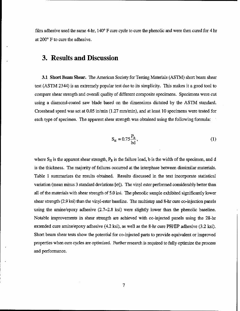
3.1 Short Beam Shear. The American Society for Testing Materials (ASTM) short beam shear
test (ASTM 2344) is an extremely popular test due to its simplicity. This makes it a good tool to
compare shear strength and overall quality of different composite specimens. Specimens were cut
using a diamond-coated saw blade based on the dimensions dictated by the ASTM standard.
Crosshead speed was set at 0.05 in/min (1.27 mm/min), and at least 10 specimens were tested for
each type of specimen. The apparent shear strength was obtained using the following formula:
SH=0.75^-, (1) H bd
where SH is the apparent shear strength, PB is the failure load, b is the width of the specimen, and d
is the thickness. The majority of failures occurred at the interphase between dissimilar materials.
Table 1 summarizes the results obtained. Results discussed in the text incorporate statistical
variation (mean minus 3 standard deviations [a]). The vinyl ester performed considerably better than
all of the materials with shear strength of 5.0 ksi. The phenolic sample exhibited significantly lower
shear strength (2.9 ksi) than the vinyl-ester baseline. The multistep and 8-hr cure co-injection panels
using the amine/epoxy adhesive (2.7-2.8 ksi) were slightly lower than the phenolic baseline.
Notable improvements in shear strength are achieved with co-injected panels using the 28-hr
extended cure amine/epoxy adhesive (4.2 ksi), as well as the 8-hr cure PH/EP adhesive (3.2 ksi).
Short beam shear tests show the potential for co-injected parts to provide equivalent or improved
properties when cure cycles are optimized. Further research is required to fully optimize the process
and performance.

Table 1. Short Beam Shear Results
Material Apparent Shear
Strength (psi)
Apparent Shear Strength
[Mean Minus 3o] (psi)
Failure Type and Location
Vinyl-Ester 411-350 5,360 ± 120 4,990 Brittle, Midplane
Phenolic J2027/L 3,280 ± 120 2,930 Brittle, Midplane
Multistep Process 3,420 ± 230 2,720 Adhesive
Co-Injected With Amine/Epoxy Adhesive (8-hr Cure)
2,970 + 70 2,760 Cohesive, Phenolic Side
Co-Injected With Amine/Epoxy Adhesive (28-hr Cure)
4,470 ± 100 4,170 Cohesive, Phenolic Side
Co-Injected With PH/EP Adhesive (8-hr Cure)
3,450 ±80 3,210 First Ply Phenolic
3.2 DCB Testing. DCB measures Mode I fracture toughness, which is a measure of the
resistance of the material to delamination within the interphase. The DCB test (ASTM D-5588)
directly loads the interphase formed during processing. The DCB test is expected to be more
sensitive to the performance of the various interphases created than the SBS test. In the DCB
specimen, an artificial flaw of known dimension was manufactured into the composite in the form
of a precrack. The specimens were then cut from the composite panel. The specimens were
approximately 24 mm wide and 300 mm long. Two blocks were then bonded to the end of the
specimen where the precrack was located to allow loading of the specimen. One of the sides of the
specimen was carefully painted, and evenly-spaced marks were placed 5 mm apart. The crosshead
speed was set at 0.5 mm/min. The specimens were placed in the fixture, and the load was applied.
As the load was applied, the crack tip propagated along the specimen. During the test, the critical
load, Per, and the crosshead displacement, \a, were recorded at every crack tip location.
These data were then used to obtain the fracture toughness of the material using the experimental
compliance method, also known as Berry's method [11]. The benefit of this method is that it enables
Gic vs. a to be determined and, consequently, the R-curve effects to be quantified through the
following relationship:

nP v G iffkla. (2)
k 2Wa
where the critical load and the crosshead displacement are measured during the test; n is the power
law index relating compliance to crack length and fit to the data based on
C = Kan. (3)
The results of the DCB tests are summarized in Table 2 and presented in Figure 3. The
vinyl-ester specimens provided the highest fracture toughness (980 J/m2) followed by the co-
injection panel using the PH7EP adhesive (730 J/m2). The other two co-injection panels exhibited
fracture toughnesses similar to the phenolic panel (530-560 J/m2). The multistep process exhibited
significant scatter in the results and yielded the lowest performance at 360 J/m2. All of the
co-injected specimens showed cohesive failure. Note that the samples that used a PH/EP adhesive
had the highest fracture toughness of any multiple resin material tested. The high Mode I fracture
toughness of this material is most likely due the chemical compatibility between the film adhesive
and the phenolic resin. Additionally, the precrack was placed both between the phenolic and the
epoxy and between the epoxy and the vinyl ester, but this did not appear to effect the results. In most
of the DCB samples, the failure was between the epoxy adhesive and the phenolic. It should also
be noted that the specimens manufactured through a multistep process exhibited undesirable
adhesive failure.
The co-injected specimens that used an epoxy/amine adhesive and were cured for only 8 hr
exhibit a unique behavior; the fracture toughness decreases with increasing crack length.
Additionally, during the tests, it was noted that the failure that occurred in the epoxy adhesive was
always extremely ductile, displaying a behavior that indicated that the epoxy had not fully cured.
This stimulated the development of the 24-hr cure cycle. A viscoelastic response exhibited by
partially cured thermoset resins would be expected to exhibit this behavior. It is difficult to
characterize the local effects on cure and viscoelastic behavior that evolves during processing and

Table 2. Summary of DCB Results
Material Fracture
Toughness (J/m2)
Fracture Toughness
[Mean Minus 38] (J/m2)
Comments
Vinyl-Ester 411-350 1,220 ±80 980 mostly brittle fracture at surface
Phenolic J2027/L 730 ± 60 550 high void content
Multistep Process 720 ±120 360 fails at adhesive/phenolic interface
Co-Injected (Amine, 8-hr Cure)
860 ±100 560 failure in adhesive on phenolic side; ductile behavior suggests material not fully cured
Co-Injected (Amine, 28-hr Cure)
740 ±70 530 cohesive failure in epoxy on phenolic side, cracks developed in first plv of phenolic
Co-Injected (PH/EP, 8-hr Cure)
940 ±70 730 cohesive failure PH/EP adhesive
1400
1200
~ 1000
CD C
JZ CJ>
o
800
600
400 -
200
m
m m
a a
a
a a
n ♦ n D n o 9
ffi . " i o o ♦ a
o o
1« ♦
a Multi-step ♦ 8 Hr. Epoxy o 28 Hr. Epoxy
m 8 Hr. Ep-Ph
' ' I 1 L ' ■ I I \ 1 1 1 1 1-
0.035 0.045 0.065 0.075 0.085 0.095 0.11 0.12
a (mm) Figure 3. Typical Mode I Fracture Toughness vs. Crack Length.
10

interphase formation. Consequently, the DCB tests were conducted at higher rates to substantiate
the mechanism.
Smiley and Pipes [12], as well as Gillespie, Carlsson, and Smiley [13] have studied the rate
effects in the DCB test and can be quantified by defining a crack opening displacement rate as the
opening displacement rate at a small arbitrary distance, e, from the crack tip. The crack opening
displacement rate, yct, is a function of both the crosshead speed, v, and the crack length, a. The
expression they derive is:
y«=^- (4)
Figure 4 shows the change in crack opening displacement rate as a function of crack length for
one of the co-injected specimens where yct changes by one order of magnitude as the crack
propagates along the specimen. Specimens were retested at a rate 10 times the original crosshead
speed (5 to 50 mm/min). Results are compared to the lower rate data and clearly show the rate effect
on Mode I fracture toughness. The decreasing fracture toughness behavior is not present at the
higher loading rate, as shown in Figure 5. It is apparent from the behavior in these co-injected
specimens that the epoxy adhesive did not fully cure. The joint exhibited rate-dependent behavior
in both the DCB and in subsequent durability tests. This finding confirms that, in co-injection, it is
not sufficient to define the cure cycle of the final part by simply combining the cure cycles of the
individual materials.
An additional proof of the fact that the viscoelastic behavior is caused by a partially cured
interphase is that the extended cure cycle (28 hr) specimens did not exhibit any kind of viscoelastic
behavior. These specimens had a slight reduction of Mode I fracture toughness as compared to the
8-hr cure specimens. The fracture toughness remained constant or increased with increasing crack
length exhibiting a traditional R-curve behavior.
11

0.0012
0.001 --
0.0008 - -
0.0006 -
0.0004
0.0002 --
♦♦ ♦ ♦
2 3 4
crack length (in.)
Figure 4. Crack Opening Displacement Rate vs. Crack Length. Data Are Normalized With Respect to the Crosshead Speed.
• 0.2 in/mi n Q 2.0 in/min
1400
1200 -
1000
800
2 600 O
400
200
0
na1- a a no nn Q
•••..••
_l I I 1 1 L.
0.05 0.1
crack length (m)
__i i i—i—i—I
0.15 0.2
Figures. Fracture Toughness vs. Crack Length for Co-Injected Specimens Tested at Different Crosshead Speeds.
12

3.3 Durability Tests. The final test conducted on the specimens was a durability test. The
wedge test (ASTM 3762) was used to evaluate the performance of the interphase under adverse
environmental conditions. The wedge test is performed on the same type of specimens used for the
DCB. A wedge was inserted into the precrack to initiate a crack. The entire specimen was then
inserted in water to simulate an adverse environment, and the crack propagation was recorded at
regular time intervals. In this test, the highly stressed crack tip was continuously exposed to room-
temperature water, and, therefore, its long-term durability could be evaluated. Figure 6 shows a
graph of crack propagation vs. time for all phenolic/vinyl-ester hybrid samples. Under initial wedge
insertion, cracks propagated and arrested to the distance at time = 0 in Figure 6. The cracks are then
measured at given time intervals over a testing period of 2 weeks. The crack in the co-injected
specimen that uses the epoxy/amine adhesive and the short cure cycle, on the other hand, keeps
propagating for longer times, exhibiting reduced durability. This is consistent with the viscoelastic
behavior observed in the DCB tests. All other materials demonstrate superior durability in this
environment.
4. Conclusions
An application of CIRTM technology has been investigated for the purpose of producing large-
scale composite structures with an integral fire barrier. Multilayer composite materials composed
of a glass-reinforced vinyl-ester structural section and a glass-reinforced phenolic fire barrier section
have been successfully manufactured using CIRTM processing. Mechanical characterization of
these materials suggests that the choice of materials is critical to the success of the CIRTM process.
A number of different alternatives were evaluated. Three different co-injected samples were
evaluated in detail. Two used the same separation material, an epoxy/amine adhesive, but different
cure cycle. One cycle was 8 hr, while the other was extended to 28 hr in order to ensure complete
cure of the materials. The third samples were manufactured using a PH/EP adhesive to improve
chemical compatibility with the phenolic resin. Investigations revealed that superior adhesion
between the layers could be achieved through the use of the extended cure cycle or the PH/EP
adhesive layer for the phenolic side of the part. Short beam shear tests show the potential for
13

£ E
70
60
50
30 -
20
—B—Multi-step -♦— 28 Hr. Epoxy -o— 8 Hr. Epoxy
■-E--8Hr. Ep-Ph / s
/
j> o- -*
-a- ■ffl
-a
0.1 10
Time (hr.)
100 1000
Figure 6. Crack Length vs. Time for All Materials Tested. The Crack Length at T = 0 Is the Crack Length After Initial Wedge Insertion. Note That Two Cracks Developed in the 28-hr Specimens and Only the Interface Crack Length Is Reported.
co-injected parts to provide equivalent or improved properties when cure cycles are optimized.
However, the panel manufactured with the epoxy/amine adhesive and the short cure cycle exhibited
inferior fracture toughness and durability and is attributed to the inhibition of cure at the PH/EP
interphase due to acid-base interactions. Interlaminar shear strength values (mean minus 3 a) of
4.2 ksi and 3.2 ksi were measured for the extended cure cycle and PH/EP adhesive specimens, as
compared to a value of 2.7 ksi for a panel made with the secondary bonding techniques. Although
CIRTM has provided superior properties and may reduce manufacturing costs, it is necessary to
carefully consider the interactions between dissimilar materials to optimize interphase properties,
structural performance, and cure cycles.
14

5. References
1. Sorathia, U., and D. Beck. "Fire Protection of Glass/Vinyl Ester Composites for Structural Composites." Proceedings of the 41st International SAMPE Symposium and Exhibition, Anaheim, CA, 24-28 March 1996.
2. Fink, B. K., J. W. Gillespie, Jr., E. F. Gillio, and K. R. Bernetich. "One-Step Resin Transfer Molding of Multi-Functional Composites Consisting of Multiple Resins." U.S. Patent Office, 22 October 1997.
3. Pike, T., M. McArthur, and D. Schade. "Vacuum Assisted Resin Transfer Molding of a Layered Structural Laminate for Application on Ground Combat Vehicles." Proceedings of the 28th International SAMPE Technical Conference, Seattle, WA, pp. 374-380,4-7 November 1996.
4. Gillio, E. F. "Co-Injection Resin Transfer Molding of Hybrid Composites." MS Thesis, University of Delaware, 1998.
5. Gillio, E. F., J. W. Gillespie, Jr., R. F. Eduljee, S. G. Advani, K. R. Bernetich, and B. K. Fink. "Manufacturing of Composites With the Co-Injection Process." Proceedings of the 38th AIAA Structures, Structural Dynamics and Materials Conference, Kissimmee, FL, 7-10 April 1997.
6. Gillio, E. F., S. G. Advani, J. W. Gillespie, Jr., and B. K. Fink. "Investigation of the Role of Transverse Flow in Co-Injection Resin Transfer Molding." Polymer Composites, Vol. 19, No. 6, December 1998.
7. Seemann, W. H., HI. "Plastic Transfer Molding Techniques for the Production of Fiber Reinforced Plastic Structures." U.S. Patent Number 4,902,215,20 February 1990.
8. Don, R. C, S. H. McKnight, E. D. Wetzel, and J. W. Gillespie, Jr. "Application of Thermoplastic Resistance Welding Techniques to Thermoset Composites." Proceedings of the Society of Plastic Engineers, San Francisco, CA, pp. 1295-1299,1994.
9. Immordino, K. M. "Characterization of the Polysulfone/Epoxy Interphase for Bonding Thermoplastic Composites." MS Thesis, University of Delaware, 1996.
10. Don, R. C, J. W. Gillespie, Jr., and S. H. McKnight. "Bonding Techniques for High-Performance Thermoplastic Compositions." U.S. Patent Number 5,643,390,1 July 1997.
11. Berry, J. P. "Determination of Fracture Energies by the Cleavage Technique." Journal of Applied Physics, vol. 34, no. 62,1963.
15

12. Smiley, A. J., and R. B. Pipes. "Rate Effects on Mode I Interlaminar Fracture Toughness in Composite Materials." Journal of Composite Materials, vol. 21, pp. 670-687, July 1987.
13. Gillespie, J. W., Jr., L. A. Carlsson, and A. J. Smiley. "Rate-Dependent Mode I Interlaminar Crack Growth Mechanisms in Graphite/Epoxy and Graphite/PEEK." Composites Science and Technology, vol. 28, no. 1, pp. 1-15,1987.
16

NO. OF COPIES ORGANIZATION
2 DEFENSE TECHNICAL INFORMATION CENTER DTICDDA 8725 JOHN J KINGMAN RD STE0944 FT BELVOIR VA 22060-6218
1 HQDA DAMOFDQ D SCHMIDT 400 ARMY PENTAGON WASHINGTON DC 20310-0460
1 OSD OUSD(A&T)/ODDDR&E(R) RJTREW THE PENTAGON WASHINGTON DC 20301-7100
1 DPTYCGFORRDA US ARMY MATERIEL CMD AMCRDA 5001 EISENHOWER AVE ALEXANDRIA VA 22333-0001
NO. OF COPIES ORGANIZATION
1 DIRECTOR US ARMY RESEARCH LAB AMSRLDD 2800 POWDER MILL RD ADELPHI MD 20783-1197
1 DIRECTOR US ARMY RESEARCH LAB AMSRL CS AS (RECORDS MGMT) 2800 POWDER MILL RD ADELPHI MD 20783-1145
3 DIRECTOR US ARMY RESEARCH LAB AMSRL CILL 2800 POWDER MILL RD ADELPHI MD 20783-1145
ABERDEEN PROVING GROUND
DIRUSARL AMSRL CI LP (BLDG 305)
INST FOR ADVNCD TCHNLGY THE UNTV OF TEXAS AT AUSTIN PO BOX 202797 AUSTIN TX 78720-2797
DARPA B KASPAR 3701 N FAIRFAX DR ARLINGTON VA 22203-1714
NAVAL SURFACE WARFARE CTR CODE B07 J PENNELLA 17320 DAHLGREN RD BLDG 1470 RM 1101 DAHLGREN VA 22448-5100
US MILITARY ACADEMY MATH SCI CTR OF EXCELLENCE DEPT OF MATHEMATICAL SCI MADNMATH THAYERHALL WEST POINT NY 10996-1786
17

NO. OF COPIES ORGANIZATION
1 DIRECTOR USARL AMSRL CP CA D SNIDER 2800 POWDER MILL RD ADELPHI MD 20783
1 COMMANDER US ARMY ARDEC AMSTA AR FSE T GORA PICATTNNY ARSENAL NJ 07806-5000
3 COMMANDER USA ARDEC AMSTA AR TD PICATTNNY ARSENAL NJ 07806-5000
5 COMMANDER USA TACOM AMSTA JSK S GOODMAN JFLORENCE AMSTA TRD BRAJU LHINOJOSA D OSTBERG WARREN MI 48397-5000
5 PM SADARM SFAE GCSS SD COL B ELLIS MDEVINE WDEMASSI JPRJTCHARD SHROWNAK PICATTNNY ARSENAL NJ 07806-5000
1 COMMANDER USA ARDEC F MCLAUGHLIN PICATTNNY ARSENAL NJ 07806-5000
1 COMMANDER USA ARDEC AMSTA AR CCH P J LUTZ PICATTNNY ARSENAL NJ 07806-5000
NO. OF COPIES ORGANIZATION
5 COMMANDER USA ARDEC AMSTA AR CCH SMUSALLI RCARR M LUCIANO TLOUCEIRO PICATTNNY ARSENAL NJ 07806-5000
4 COMMANDER USA ARDEC AMSTAAR(2CPS) E FENNEL (2 CPS) PICAT1NNY ARSENAL NJ 07806-5000
1 COMMANDER USA ARDEC AMSTA AR FSF T C LIVECCHIA PICATTNNY ARSENAL NJ 07806-5000
1 COMMANDER USA ARDEC AMSTA AR QAC T/C C PATEL PICATTNNY ARSENAL NJ 07806-5000
2 COMMANDER USA ARDEC AMSTA ARM DDEMELLA FDIORIO PICATTNNY ARSENAL NJ 07806-5000
3 COMMANDER USA ARDEC AMSTA AR FSA AWARNASH BMACHAK MCHDEFA PICATTNNY ARSENAL NJ 07806-5000
18

NO. OF NO. OF COPIES ORGANIZATION COPIES ORGANIZATION
1 COMMANDER 1 US ARMY COLD REGIONS ' SMCWV QAE Q RESEARCH & ENGINEERING CTR
BVANINA PDUTTA BLDG 44 WATERVLIET ARSENAL 72LYMERD
' WATERVLIETNY 12189-4050 HANVOVERNH 03755
1 COMMANDER 1 DIRECTOR SMCWV SPM USARL TMCCLOSKEY AMSRL WT L D WOODBURY BLDG 253 WATERVLIET ARSENAL 2800 POWDER MILL RD WATERVLIETNY 12189-4050 ADELPHI MD 20783-1145
8 DIRECTOR 1 COMMANDER BENET LABORATORIES USA MICOM AMSTA AR CCB AMSMI RD W MCCORKLE JKEANE REDSTONE ARSENAL AL JBATTAGLIA 35898-5247 JVASILAKIS GFFIAR 1 COMMANDER V MONTVORI USA MICOM GDANDREA AMSMI RD ST P DOYLE R HASENBEIN REDSTONE ARSENAL AL AMSTA AR CCB R 35898-5247 S SOPOK WATERVLIETNY 12189-4050 1 COMMANDER
USA MICOM 1 COMMANDER AMSMI RD ST CN T VANDTVER
SMCWV QA QS KINSCO REDSTONE ARSENAL AL WATERVLIETNY 12189-4050 35898-5247
1 COMMANDER 3 US ARMY RESEARCH OFFICE PRODUCTION BASE MODERN ACTY A CROWSON AMSMC PBM K KLOGAN PICATINNY ARSENAL NJ JCHANDRA 07806-5000 PO BOX 12211
RESEARCH TRIANGLE PARK NC 1 COMMANDER
USA BELVOIR RD&E CTR 27709-2211
STRBEJBC 3 US ARMY RESEARCH OFFICE FT BELVOIR VA 22060-5606 ENGINEERING SCIENCES DIV
R SINGLETON 2 COMMANDER G ANDERSON
USA ARDEC KIYER AMSTA AR FSB G PO BOX 12211
• M SCHIKSNIS RESEARCH TRIANGLE PARK NC D CARLUCCI 27709-2211 PICATINNY ARSENAL NJ 07806-5000
19

NO. OF COPIES ORGANIZATION
5 PMTMAS SFAE GSSC TMA COLPAWLICKI KKIMKER EKOPACZ RROESER B DORCY PICATINNY ARSENAL NJ 07806-5000
1 PMTMAS SFAE GSSC TMA SMD R KOWALSKI PICATINNY ARSENAL NJ 07806-5000
3 PEO FIELD ARTILLERY SYSTEMS SFAE FAS PM H GOLDMAN TMCWTLLIAMS T LINDSAY PICATINNY ARSENAL NJ 07806-5000
2 PM CRUSADER GDELCOCO J SHIELDS PICATINNY ARSENAL NJ 07806-5000
3 NASA LANGLEY RESEARCH CTR MS 266 AMSRLVS WELBER FBARTLETTJR CDAVTLA HAMPTON VA 23681-0001
2 COMMANDER DARPA SWAX 2701 N FAIRFAX DR ARLINGTON VA 22203-1714
NO. OF COPIES ORGANIZATION
6 COMMANDER WRIGHT PATTERSON AFB WLFW A MAYER WLMLBM S DONALDSON TBENSON-TOLLE C BROWNING J MCCOY FABRAMS 2941PSTSTE1 DAYTON OH 45433
2 NAVAL SURFACE WARFARE CTR DAHLGREN DIV CODE G06 R HUBBARD CODE G33 C DAHLGREN VA 22448
1 NAVAL RESEARCH LAB IWOLOCKCODE6383 WASHINGTON DC 20375-5000
1 OFFICE OF NAVAL RESEARCH MECHDIV Y RAJAPAKSE CODE 1132SM ARLINGTON VA 22271
1 NAVAL SURFACE WARFARE CTR CRANE DIV M JOHNSON CODE 20H4 LOUISVILLE KY 40214-5245
1 DAVJD TAYLOR RESEARCH CTR SHIP STRUCTURES & PROTECTION DEPT J CORRADO CODE 1702 BETHESDAMD 20084
2 DAVID TAYLOR RESEARCH CTR R ROCKWELL WPHYILLAIER BETHESDA MD 20054-5000
1 DEFENSE NUCLEAR AGENCY INNOVATIVE CONCEPTS DIV RROHR 6801 TELEGRAPH RD ALEXANDRIA VA 22310-3398
20
NO. OF COPIES ORGANIZATION
1 EXPEDITIONARY WARFARE DIVN85FSHOUP 2000 NAVY PENTAGON WASHINGTON DC 20350-2000
1 OFFICE OF NAVAL RESEARCH D SIEGEL 351 800NQUINCYST ARLINGTON VA 22217-5660
7 NAVAL SURFACE WARFARE CTR JH FRANCIS CODE G30 D WILSON CODE G32 R D COOPER CODE G32 EROWECODEG33 TDURANCODEG33 L DE SIMONE CODE G33 DAHLGREN VA 22448
1 COMMANDER NAVAL SEA SYSTEM CMD PLIESE 2351 JEFFERSON DAVIS HIGHWAY ARLINGTON VA 22242-5160
1 NAVAL SURFACE WARFARE CTR ME LACY CODE B02 17320 DAHLGREN RD DAHLGREN VA 22448
1 NAVAL WARFARE SURFACE CTR TECH LIBRARY CODE 323 17320 DAHLGREN RD DAHLGREN VA 22448
4 DIR LLNL RCHRISTENSEN S DETERESA FMAGNESS M FINGER PO BOX 808 LIVERMORE CA 94550
2 DIRECTOR LLNL FADDESSIOMSB216 JREPPAMSF668 PO BOX 1633 LOS ALAMOS NM 87545
NO. OF COPIES ORGANIZATION
3 UNITED DEFENSE LP 4800 EAST RIVER DR PJANKEMS170 TGIOVANETTIMS236 BVANWYKMS389 MINNEAPOLIS MN 55421-1498
4 DIRECTOR SANDIA NATIONAL LAB APPLIED MECHANICS DEPT DIV 8241 WKAWAHARA KPERANO D DAWSON PNIELAN PO BOX 969 LIVERMORE CA 94550-0096
1 BATTALLE CRHARGREAVES 505KNIGAVE COLUMBUS OH 43201-2681
1 PACIFIC NORTHWEST LAB M SMITH PO BOX 999 RICHLAND WA 99352
1 LLNL M MURPHY PO BOX 808 L 282 LIVERMORE CA 94550
10 UNIV OF DELAWARE CTR FOR COMPOSITE MATERIALS JGJLLESPJE 201 SPENCER LAB NEWARK DE 19716
2 THE U OF TEXAS AT AUSTIN CTR ELECTROMECHANICS A WALLIS JKITZMTLLER 10100 BURNETRD AUSTIN TX 78758-4497
1 AAI CORPORATION T G STASTNY PO BOX 126 HUNT VALLEY MD 21030-0126
21

NO. OF COPIES ORGANIZATION
1 SAIC DDAKIN 2200 POWELL ST STE 1090 EMERYVILLE CA 94608
1 SAIC M PALMER 2109 AIR PARK RDSE ALBUQUERQUE NM 87106
1 SAIC RACEBAL 1225 JOHNSON FERRY RD STE 100 MARIETTA GA 30068
1 SAIC G CHRYSSOMALLIS 3800 W 80TH ST STE 1090 BLOOMINGTON MN 55431
6 ALLIANT TECHSYSTEMS INC CCANDLAND RBECKER LLEE RLONG DKAMDAR GKASSUELKE 600 2ND ST NE HOPKINS MN 55343-8367
1 CUSTOM ANALYTICAL ENGR SYS INC A ALEXANDER 13000 TENSOR LANE NE FLINTSTONE MD 21530
1 NOESIS INC 1110 GLEBE RD STE 250 ARLINGTON VA 22201-4795
1 ARROW TECH ASSO 1233 SHELBURNE RD STE D 8 SOUTH BURLINGTON VT 05403-7700
NO. OF COPIES ORGANIZATION
5 GEN CORP AEROJET DPJLLASCH TCOULTER CFLYNN DRUBAREZUL MGREINER 1100 WEST HOLLYVALE ST AZUSACA 91702-0296
1 NIST STRUCTURE & MECHANICS GRP POLYMER DIV POLYMERS RM A209 GMCKENNA GAITHERSBURG MD 20899
1 GENERAL DYNAMICS LAND SYSTEM DIVISION DBARTLE PO BOX 1901 WARREN MI 48090
4 INSTITUTE FOR ADVANCED TECHNOLOGY HFAIR P SULLIVAN W REINECKE IMCNAB 4030 2 W BRAKER LN AUSTIN TX 78759
1 PM ADVANCED CONCEPTS LORAL VOUGHT SYSTEMS J TAYLOR MS WT 21 PO BOX 650003 DALLAS TX 76265-0003
2 UNTIED DEFENSE LP PPARA G THOMASA 1107 COLEMAN AVE BOX 367 SAN JOSE CA 95103
1 MARINE CORPS SYSTEMS CMD PM GROUND WPNS COL R OWEN 2083 BARNETT AVE STE 315 QUANTICO VA 22134-5000
22

NO. OF COPIES
1
ORGANIZATION
OFFICE OF NAVAL RES JKELLY 800 NORTH QUINCEY ST ARLINGTON VA 22217-5000
NAVSEE OJRI G CAMPONESCHI 2351 JEFFERSON DAVIS HWY ARLINGTON VA 22242-5160
USAF WLMLSOLAHAKJM 5525 BAILEY LOOP 243E MCCLELLAN AFB CA 55552
NASALANGLEY J MASTERS MS 389 HAMPTON VA 23662-5225
FAA TECH CTR DOPLINGERAAR431 P SHYPRYKEVICH AAR 431 ATLANTIC CITY NJ 08405
NASALANGLEYRC CCPOEMS188E NEWPORT NEWS VA 23608
USAF WLMLBC ESHINN 2941 PST STE 1 WRIGHT PATTERSON AFB OH 45433-7750
NIST POLYMERS DIVISION RPARNAS JDUNKERS M VANLANDINGHAM D HUNSTON GAITHERSBURG MD 20899
NO. OF COPIES ORGANIZATION
1 COMMANDER USA ARDEC INDUSTRIAL ECOLOGY CTR TSACHAR BLDG 172 PICAHNNY ARSENAL NJ 07806-5000
1 COMMANDER USA ATCOM AVIATION APPLIED TECH DIR J SCHUCK FT EUSTISVA 23604
1 COMMANDER USA ARDEC AMSTAARSRE DYEE PICATINNY ARSENAL NJ 07806-5000
1 COMMANDER USA ARDEC AMSTAARQAC TDRIGOGLIOSO BLDG 354 M829E3IPT PICATINNY ARSENAL NJ 07806-5000
7 COMMANDER USA ARDEC AMSTAARCCHB BKONRAD ERTVERA GEUSTICE SPATEL GWAGNECZ RSAYER FCHANG BLDG 65 PICATINNY ARSENAL NJ 07806-5000
OAK RIDGE NATIONAL LAB A WERESZCZAK BLDG 4515 MS 6069 PO BOX 2008 OAKRIDGE TN 37831-6064
23

NO. OF COPIES ORGANIZATION
ABERDEEN PROVING GROUND
74 DIR USARL AMSRLCI AMSRL CIC W STUREK AMSRLCI CBR KASTE AMSRL CIS A MARK AMSRL SLB AMSRL SLBA AMSRL SLBLDBELY AMSRL SLI AMSRL WMB
AHORST E SCHMIDT
AMSRL WM BE GWREN CLEVERITT D KOOKER
AMSRL WMBD P PLOSTTNS DLYON JNEWHL S WDLKERSON RFIFER B FORCH R PESCE RODRIGUEZ BRICE
AMSRL WM D VIECHNICKIE GHAGNAUER J MCCAULEY
AMSRL WM MA RSHUFORD S MCKNIGHT L GHIORSE
AMSRL WM MB VHARIK JSANDS B BURNS WDRYSDALE J BENDER TBLANAS TBOGETTI R BOSSOLI LBURTON S CORNELISON PDEHMER RDOOLEY BFINK G GAZONAS
NO. OF COPIES ORGANIZATION
S GHIORSE DGRANVILLE D HOPKINS C HOPPEL DHENRY R KASTE MLEADORE RLIEB E RIGAS D SPAGNUOLO W SPURGEON
AMSRL WM MB J TZENG AMSRL WM MB ALC
AABRAHAMIAN M BERMAN AFRYDMAN TLI WMCINTOSH E SZYMANSKI
AMSRL WM MC J BEATTY AMSRL WM MD W ROY AMSRL WM T D DIETRICH AMSRL WMTA
W GILLICH ERAPACKI THAVEL
AMSRL WMTC R COATES W DE ROSSET
AMSRL WM TD WBRUCHEY AD GUPTA
AMSRL WMBA FBRANDON WDAMICO
AMSRL WM BR J BORNSTEIN AMSRL WM TE A NEUER AMSRL WM BR J LACETERA
24

REPORT DOCUMENTATION PAGE Form Approved OMB No. 0704-0186
Public reporting burden for this collection ol Information Is estimated to average 1 hour per response, Including the time tor reviewing Instructions, searching existing data sources, gathering and maintaining the data needed, and completing and reviewing the collection of Information. Send comments regarding this burden estimate or any other aspect of this collection of Information, Including suggestions for reducing this burden, to Washington Headquarters Services, Directorate for Information Operations and Reports, 1216 Jefferson Davis Hlohwav. Suite 1804. Arllnoton. VA 22202-4302. and to the Office of Mananem«nt and Budoet. Paperwork Reduction Prolectn»70»0188). Washlnoton. DC 20503,
1. AGENCY USE ONLY (Leave blank) \ 2. REPORT DATE I 3. REPORT TYPE AND DATES COVERED
January 2000 Final, January 1996 - December 1997 4. TITLE AND SUBTITLE
Co-Injection Resin Transfer Molding of Vinyl-Ester and Phenolic Composites
6. AUTHOR(S)
Bruce K. Fink, Emanuele F. Gillio,* Geoffrey P. McKnight, John W. Gillespie Jr.,* Suresh G. Advani,* Rushad F. Eduljee,* and Karl R. Bemetich
5. FUNDING NUMBERS
AH42
7. PERFORMING ORGANIZATION NAME(S) AND ADDRESS(ES)
U.S. Army Research Laboratory ATTN: AMSRL-WM-MB Aberdeen Proving Ground, MD 21005-5069
8. PERFORMING ORGANIZATION REPORT NUMBER
ARL-TR-2150
9. SPONSORING/MONITORING AGENCY NAMES(S) AND ADDRESS(ES) 10.SPONSORING/MONITORING AGENCY REPORT NUMBER
11. SUPPLEMENTARY NOTES
♦University of Delaware, Newark, DE 19716
12a. DISTRIBUTION/AVAILABILITY STATEMENT
Approved for public release; distribution is unlimited.
12b. DISTRIBUTION CODE
13. ABSTRACT (Maximum 200 words)
Vacuum-assisted resin transfer molding (VARTM)-type processes have been proven cost-effective manufacturing techniques for large composite structures. However, their use has been limited to a single resin system. Many composite structures require multiple resins to serve different purposes while being integrated into a single structure. Co-injection resin transfer molding (CIRTM) is a new manufacturing process developed by the U.S. Army Research Laboratory (ARL) with the University of Delaware that enables the user to manufacture multilayer hybrid composite parts in a single processing step. In this report, CIRTM is used to manufacture a dual-layered structure consisting of a vinyl-ester layer for structural integrity and a phenolic layer for fire, smoke, and toxicity protection. The two resins are simultaneously injected into a mold filled with a stationary fiber bed and are co-cured. Resin separation is maintained by a 1-mil-thick polysulfone film sandwiched between two layers of 6.5-mil-thick adhesive. A differential scanning calorimeter (DSC) is used to select the optimum cure cycle for all of the materials. Mechanical testing is used to evaluate the performance of the interphase formed between dissimilar materials. Experimental results show that co-injected, co-cured materials offer equivalent properties or, in some cases, more superior properties, than those provided by single-injection resin composites. This case is used to develop and present a methodology that can be followed to co-inject different resins.
14. SUBJECT TERMS
co-injection resin transfer molding, vinyl ester, phenolic, flammability, composite materials
17. SECURITY CLASSIFICATION OF REPORT
UNCLASSIFIED
18. SECURITY CLASSIFICATION OF THIS PAGE
UNCLASSIFIED
19. SECURITY CLASSIFICATION OF ABSTRACT
UNCLASSIFIED
15. NUMBER OF PAGES
30 16. PRICE CODE
20. LIMITATION OF ABSTRACT
UL NSN 7540-01-280-5500 25
Standard Form 298 (Rev. 2-89) Prescribed by ANSI Std. 239-18 298-102

INTENTIONALLY LEFT BLANK.
26

USER EVALUATION SHEET/CHANGE OF ADDRESS
This Laboratory undertakes a continuing effort to improve the quality of the reports it publishes. Your comments/answers to the items/questions below will aid us in our efforts.
1. ARL Report Number/Author ARL-TR-2150 (Fink) Date of Report January 2000
2. Date Report Received
3. Does this report satisfy a need? (Comment on purpose, related project, or other area of interest for which the report will
be used.)
4. Specifically, how is the report being used? (Information source, design data, procedure, source of ideas, etc.).
5. Has the information in this report led to any quantitative savings as far as man-hours or dollars saved, operating costs
avoided, or efficiencies achieved, etc? If so, please elaborate.
6. General Comments. What do you think should be changed to improve future reports? (Indicate changes to organization,
technical content, format, etc.)
Organization
CURRENT Name E-mail Name ADDRESS
Street or P.O. Box No.
City, State, Zip Code
7. If indicating a Change of Address or Address Correction, please provide the Current or Correct address above and the Old
or Incorrect address below.
Organization
OLD Name ADDRESS
Street or P.O. Box No.
City, State, Zip Code
(Remove this sheet, fold as indicated, tape closed, and mail.) (DO NOT STAPLE)
DEPARTMENT OF THE ARMY
OFFICIAL BUSINESS
BUSINESS REPLY MAIL FIRST CLASS PERMIT NO 0001,APG,MD 3 POSTAGE WILL BE PAID BY ADDRESSEE
DIRECTOR US ARMY RESEARCH LABORATORY ATTN AMSRLWMMB ABERDEEN PROVING GROUND MD 21005-5069
NO POSTAGE NECESSARY
IF MAILED IN THE
UNITED STATES