cngs project: status report
TRANSCRIPT

23 August 2005 Malika Meddahi 1
CNGS Project: Status report
1. Project Overview
2. Proton beam layout and equipment status
3. Proton beam dynamics
4. Target and secondary beam equipment
readiness
5. Commissioning preparation
6. Outlook

23 August 2005 Malika Meddahi 2
(see http://cern.ch/cngs)CNGS – a long base-line neutrino beam facility (732 km)
send µ beam -> detect appearance
CNGS project at CERN: production of the µ beam
using protons from the existing accelerator chain
1. Project Overview
At Gran Sasso:
OPERA detecting

23 August 2005 Malika Meddahi 3
CNGS: the main components
vacuum
700 m 100 m 1000m 67 m
p + C (interactions) +, K+, (µ+) (decay in flight) µ+ + µ

23 August 2005 Malika Meddahi 4

23 August 2005 Malika Meddahi 5
2. Proton beam line layout and
equipment status

23 August 2005 Malika Meddahi 6
Proton beam line overview

23 August 2005 Malika Meddahi 7
TA40
TT40
TT40
Beam
Dump
TED
Safety beam
stopper
SPS
SPS
extraction
point
to CNGS
target
to LHC
SPS beam
CNGS&LHC beam
MBHC 13mrad
MBHA 15mrad
MBSG 25mrad
TT41 extraction point to beam dump

23 August 2005 Malika Meddahi 8
Electrical
distribution box
BPM
control
box
Magnet
Interlock
box
Transfer line layout: half cell
MBGMDG
QTG
5.6% slope
BEAM
BEAM

23 August 2005 Malika Meddahi 9
MBG 73 magnets (78 ordered)
Gap height 37 mm
Nominal field : 1.7 T @ 400 GeV
Magnetic length : 6.3 m
ALL RECEIVED and stored
Main dipole magnet status

23 August 2005 Malika Meddahi 10TT41 mock-up

23 August 2005 Malika Meddahi 11

23 August 2005 Malika Meddahi 12
QTG 20 magnets (23 ordered)
Nominal gradient 40 T/m, 2.2 m long
Magnetic aperture : 45 mm
All QTG received
All QTG installed in TT41 and aligned
Main quadrupole magnet status

23 August 2005 Malika Meddahi 13
Quadrupole installation
in TT41

23 August 2005 Malika Meddahi 14
MDG 12 magnets (17 ordered)
Bending angle 80 µrad, overall length: 700mm
Gap height : 45 mm
All MDG magnets received
Chambers to be inserted in 4 MDGH (at CERN)
Dipole corrector magnet status

23 August 2005 Malika Meddahi 15
MDGH and MDGV
Dipole corrector magnets

23 August 2005 Malika Meddahi 16
Last 200m
Final focusing
6 QTL
2QTS
Target T40
Beam
Strong correctors
2 MDSH
2MDSV
Beam

23 August 2005 Malika Meddahi 17
• 18 beam position monitors in proton beam line
(BPG) + 4 in common line with LHC (BPK)
• 1 coupler in air on target table (BPKG)
• 8 proton beam profile monitors (BTVG)
• 18 beam loss monitors (BLM)
• 1 beam current transformer (BFCT) (+1 BFCT in
common line with LHC
Beam line instrumentation

23 August 2005 Malika Meddahi 18
Beam Position Monitoring
Beam Position Measurement Requirements
18 Button Electrode
BPGs in TT41
60mm Aperture
110
340
110
BPCKD (double)
short circuits
BEAM 4 Stripline Couplers in TT40
will see both LHC & CNGS beams
Original
Modified

23 August 2005 Malika Meddahi 19
BPG beam position monitors – mounted on QTGs

23 August 2005 Malika Meddahi 20
Target Beam Position Monitor
Final standard BPG of the proton beam line & target BPKG
used to provide position at the target
setting up performed using final beam line BPG
aiming at target rods verified & tracked using target BPKG
accuracy of measurement ±0.2mm in ±2mm central region.
accuracy of measurement ±0.5mm outside ±2mm central region.
Target Beam Position Measurement Requirements

23 August 2005 Malika Meddahi 21
BPKG – special beam position monitor on target table
Stripline Coupler Pick-up operated in air

23 August 2005 Malika Meddahi 22
75 µm carbon and 12 µm titanium screens
5 to 10 % precision requested
Ti screen “in”
Beam Profile monitors

23 August 2005 Malika Meddahi 23
Beam Loss Monitoring
Beam losses will be detected using:
18 standard 1 litre, SPS, nitrogen filled ionisation chambers 30 parallel plates with 5mm separation - ionisation length of 19cm efficiency of ~1250 pairs per primary charge

23 August 2005 Malika Meddahi 24
Beam Current Transformers
First BCT sees both LHC &
CNGS beams
• Has to fulfill additional requirementof LHC bunch by bunch capability
(i.e. 25ns resolution)

23 August 2005 Malika Meddahi 25
3. Proton beam dynamics

23 August 2005 Malika Meddahi 26
Nominal beam parameters
Beam parameters Nominal CNGS beam
Nominal energy [GeV] 400
Normalized emittance [ µm] H=12 V=7
Emittance [ µm] H=0.028 V= 0.016
Momentum spread p/p 0.07 % +/- 20%
# extractions per cycle 2 separated by 50 ms
Batch length [ µs] 10.5
# of bunches per pulse 2100
Intensity per extraction [10 13 p] 2.4
Bunch length [ns] (4 ) 2
Bunch spacing [ns] 5
Upgrade
phase:
3.5 1013 p

23 August 2005 Malika Meddahi 27
Nominal parameters : • Beta at focus : 10 m, 20m
• Beam size at 400 GeV : 0.5 mm
• Beam divergence ’ at 400 GeV : 0.05, 0.03 mrad
Optics at Target
Possible to increase further the beam size

23 August 2005 Malika Meddahi 28
Trajectory correction scheme
2-in-3 scheme: 2 consecutive half cells per plane out of 3 are
equipped with Beam Position Monitors (BPMs) and correctors.
Phase advance per cell: /2
Beam line errors (quad displacement, beam position monitor,
dipole field and tilt, extraction from SPS)
X before trajectory. Correction 3.6 15.
X after trajectory correction 0.7 2.7
Y before trajectory. Correction 3.2 8.
Y after trajectory correction 0.6 2.5
Max. RMS Max. Excursion
(mm)
Note: max. trajectory excursion allowed: 4 mm
The implemented correction scheme is sufficient

23 August 2005 Malika Meddahi 29
Beam stability at the target
Target resistance to non-centered beam
Beam line imperfections (quad displacement, beam position monitor,
main dipole field and tilt, extraction, power supply precision)
Horizontal spot size is dominated by extraction errors
Vertical spot size is not increased, vertical beam position
is determined by trajectory errors.

23 August 2005 Malika Meddahi 30
Type of error Error
magnitude
Horizontal x
at target
(mm)
Magnet errors
Horizontal extraction angle
Horizontal extraction position
As in specs.
10 µrad r.m.s.
0.5 mm r.m.s.
0.12 mm
0.11mm
0.32 mm
0.53 mm
0.64 mm
11 µrad
5 µrad
21 µrad
53 µrad
57 µrad
Horizontal ’xat target
(µrad)
Nominal beam [r.m.s.]
Effective beam [r.m.s.]

23 August 2005 Malika Meddahi 31
MKE – extraction kicker
post-kick ripple also
very important !!
± 1% MKE field ripple 0.2 8 0.4
± 1.5% MKE field ripple 0.24 12 0.48
xat
target(mm)
’xat
target (µrad)
2 xat
target(mm)
2 such pules needed, 50ms apart

23 August 2005 Malika Meddahi 32
Aperture studies
For nominal beam parameters and expected errors
-> no beam loss is expected.
For the most critical parameters
-> a margin of a factor 2 found
Upper limits for possible injection errors have been established.

23 August 2005 Malika Meddahi 33
4. Target and secondary beam
equipment readiness

23 August 2005 Malika Meddahi 34
Downstream
Window
Target Support
Sealed
finned tube
Inert
gas
End c
ap
End c
ap
Upstream
Window
The target unit is conceived as a
static sealed system filled with 0.5
bar of He.
MATERIALS
Tube: Al-Mg alloy
Windows: Be by Brush & Wellman
Target Support: Carbon Fiber reinforced
Carbon
Target rod: Fine-grain graphite,
sintered carbon, C-C composite
Centr
al tub
e
“Graphite rods”, L = 10 cm, = 5 / 4 mm
Target Station

23 August 2005 Malika Meddahi 35
The target units

23 August 2005 Malika Meddahi 36
-80
-60
-40
-20
0
20
40
60
80
100
120
0 4 8 12 16 20 24
Support seat No.
Dif
fere
nc
e [
um
]
Laser Tracker
MetrologyC-C supports
Beam
C-C Tube
C-C Tube
Laser Tracker
Target rods: alignment

23 August 2005 Malika Meddahi 37
Target Magazine + BPKG
Indexing finger
BPKG
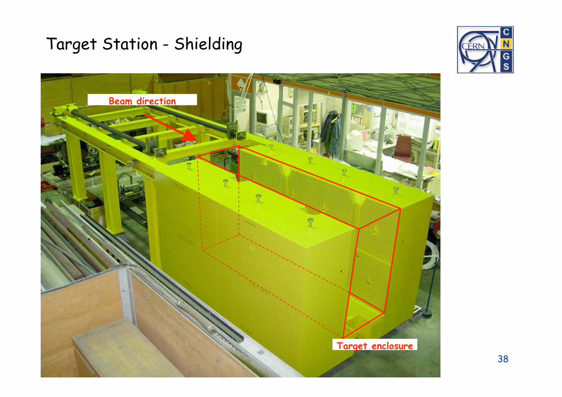
23 August 2005 Malika Meddahi 38
Target enclosure
Beam direction
Target Station - Shielding

23 August 2005 Malika Meddahi 39

23 August 2005 Malika Meddahi 40

23 August 2005 Malika Meddahi 41
Design criteria:
>95% probability to work for 5x10⁷ pulses
length: 6.5 m
diameter: 70 cm
weight: 1500 kg
Pulsed devices:150kA / 180 kA, 1 ms
water-cooled:
distributed nozzles
Horn system

23 August 2005 Malika Meddahi 42

23 August 2005 Malika Meddahi 43
The CNGS horn“today”

23 August 2005 Malika Meddahi 44
Glass Disk Glass Disk –– the remaining big issue the remaining big issue
Received from LAL
After modification
Cracks discovered ~weeks
after electrical tests
Glass plate broken
Problem = conceptual

23 August 2005 Malika Meddahi 45
Muon Monitoring Muon detectors
67m
Access very rare

23 August 2005 Malika Meddahi 46
LHC type beam loss monitor
– Parallel electrodes separated
by 0.5cm
– Stainless steel cylinder
– Al electrodes
– N2 gas filling at 1-1.1 bar

Radiation hard
camera 5m upstream
Monitor Layout
17 fixed monitors mounted on cross shapedstructure (Al)
Possibility to double number of monitors
1 movable chamber behind fixed monitorsfor relative calibration
Movement by stepping motors

23 August 2005 Malika Meddahi 48
5. Commissioning preparation

23 August 2005 Malika Meddahi 49
First and last opportunity to check the CNGS beam extraction
before the start up in May 2006
•Tests the extraction channel with CNGS beam and double pulse
extraction
• MKE kicker magnets & circulating SPS beam
• BPKG test in air
First checks of CNGS beam extraction
done in September 2004

23 August 2005 Malika Meddahi 50
Beam
dump
Safety beam
stopper
SPS
extraction
point
to target
to LHC
SPS beam
CNGS&LHC beam
Beam loss
monitors
Profiles ProfilesProfiles
Beam
Current
Monitor
TA40
TT40
TT40
SPS
SPS
extraction
point

23 August 2005 Malika Meddahi 51

23 August 2005 Malika Meddahi 52
High intensity test in the SPS
During 2004, high intensity tests allow to reproduce the previous 1996
record in terms of intensity per cycle : 4.8 1013 protons, with record value
of 5.3 1013 protons
Beam losses and induced radiation are the most critical issues for the
whole complex (extraction in the PS, low energy losses in the SPS,
SPS extraction losses)
Reduction of the beam losses is the operation goal in order to deliver the
committed number of protons in a reliable and sustainable way

23 August 2005 Malika Meddahi 53
MKE – extraction kicker, AB/BT
CERN SPS CNGS extraction kick MKE LSS4
-0.2
0
0.2
0.4
0.6
0.8
1
1.2
-5 0 5 10 15 20
Time [us]
B [
a.u
.] post-kick ripple reduced
Measured extraction kicker field
Flat top ripple in specs

23 August 2005 Malika Meddahi 54
Extraction kick pulse parameters
Rise time 1.05 µs 1.05 µs 1.05 µs
Fall time 1.05 µs 1.05 µs 1.05 µs
Usable batch length 2x10.5µs 2x10.4µs 2x 10.5µs
Flat top field ripple < 2% < 2% < 2%
Post kick pulse ripple < 2% < 4% < 2%
Requested Achieved
No damper
Achieved
with damper

23 August 2005 Malika Meddahi 55
- Hardware commissioning Feb. – April 2006
Beam instrumentations
Power supplies
Magnets (polarities)
Vacuum system
- “Dry runs” April – May 2006
Timing
Controls
Interlocks
Beam permit
Magnets (current & polarities)
- Commissioning with beam 2006: weeks 22, 25 and 27
Commissioning schedule

23 August 2005 Malika Meddahi 56
Week 22 : low intensity, up to target
Week 25 : low to medium intensity, secondary beam
Week 27 : high intensity, full facility
Commissioning schedule (draft)

23 August 2005 Malika Meddahi 57
Commissioning team, mandate, list of subjects to be addressedwere defined
23 August 2005 Malika Meddahi 58
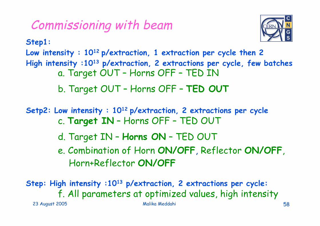
Commissioning with beam
a. Target OUT – Horns OFF – TED IN
Step1:
Low intensity : 1012 p/extraction, 1 extraction per cycle then 2
High intensity :1013 p/extraction, 2 extractions per cycle, few batches
b. Target OUT – Horns OFF – TED OUT
c. Target IN – Horns OFF – TED OUTSetp2: Low intensity : 1012 p/extraction, 2 extractions per cycle
d. Target IN – Horns ON – TED OUT
e. Combination of Horn ON/OFF, Reflector ON/OFF,
Horn+Reflector ON/OFF
f. All parameters at optimized values, high intensity Step: High intensity :1013 p/extraction, 2 extractions per cycle:

23 August 2005 Malika Meddahi 59
6. Outlook

23 August 2005 Malika Meddahi 60
TAG41
TSG4TCC4

23 August 2005 Malika Meddahi 61TAG41 Access Gallery

23 August 2005 Malika Meddahi 62
target chamberproton beam
service gallery
Target Chamber: Shielding
Target chamber July 2004 Target chamber August 2005

23 August 2005 Malika Meddahi 63
beam

23 August 2005 Malika Meddahi 64
Target Chamber: Helium Tanks
Length ~5m
Diameter 800/1200mm
20 mbar over-pressure
Alu Helium tube sleeve

23 August 2005 Malika Meddahi 65
Progress of works – Target chamber
20 July 2005:
last element
of He tube
installed

23 August 2005 Malika Meddahi 66
TCC4

23 August 2005 Malika Meddahi 67
TSG4
TSG4 Service Gallery
23 August 2005 Malika Meddahi 68
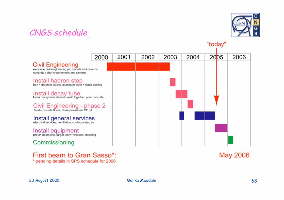
CNGS schedule

23 August 2005 Malika Meddahi 69
SummarySummary
-> Procurement of last equipment is being complete
-> Installation is well underway
-> Commissioning with beam:
to start week 22 (29 May 2006)
-> CNGS beam operational after week 27 (July 2006)

23 August 2005 Malika Meddahi 70

23 August 2005 Malika Meddahi 71
BPM1
BTV1
BFCTBPM2 BPM3
BTV2 BTV3
3 m5 m 5 m
TBID
2 BLMs

Muon Monitors
Monitoring of:
muon intensity
muon beam profile shape
muon beam profile centre
Muon intensity:
Up to 7.7x10⁷ per cm2 and 10.5 s
Dynamic range: 105
Accuracies:
absolute 10 %
relative 3 %
reproducibility: cycle to cycle 1%, one year 5%

Muon Profiles in Pit 1Muon Monitors
1st muon pit
part
/cm
2/1
013p
ot
107
105
FLUKA simulations
An updated calculation of neutron fluence in the CNGS first muon pit,
A. Ferrari, A. Guglielmi, P.R. Sala
Beam dump extent

Muon Profiles in Pit 2
2nd muon pit
/cm
2/1
013p
ot
105
104
Muon Monitors
_ target in, magnetic field
target in, no magnetic field
no target
FLUKA simulations
(P. Sala, not published)

Muon Information from GranSasso
With sufficient beam intensity
measure muons from _ interactionsin Gran Sasso rock
later: receive time stamp of muons
Expected muon fluence for thenominal CNGS beam intensity(FLUKA)
43.6 /m2/1019 pot
0.98 /m2/day or
196 /m2/y
Muon spectrum peaks at lowenergies: <p> = 16.2GeV/c.
