cnc turning center with 2 spindles, 2 turrets and 1 y-axis ... · cnc turning center with 2...
TRANSCRIPT

EXTERNAL VIEW
CNC Turning Center with 2 Spindles, 2 Turrets and 1 Y-axis Slide
BNE-34S5/51S5
883 175
630
1.020
1,200
695
1,925
1,865 475 1,505 400
2,690 2,080
350
BNE-34SY5/51SY5
883 175
630
1.020
185
1,200
695
2,080
1,865 475 1,505 400
2,690 2,080
350
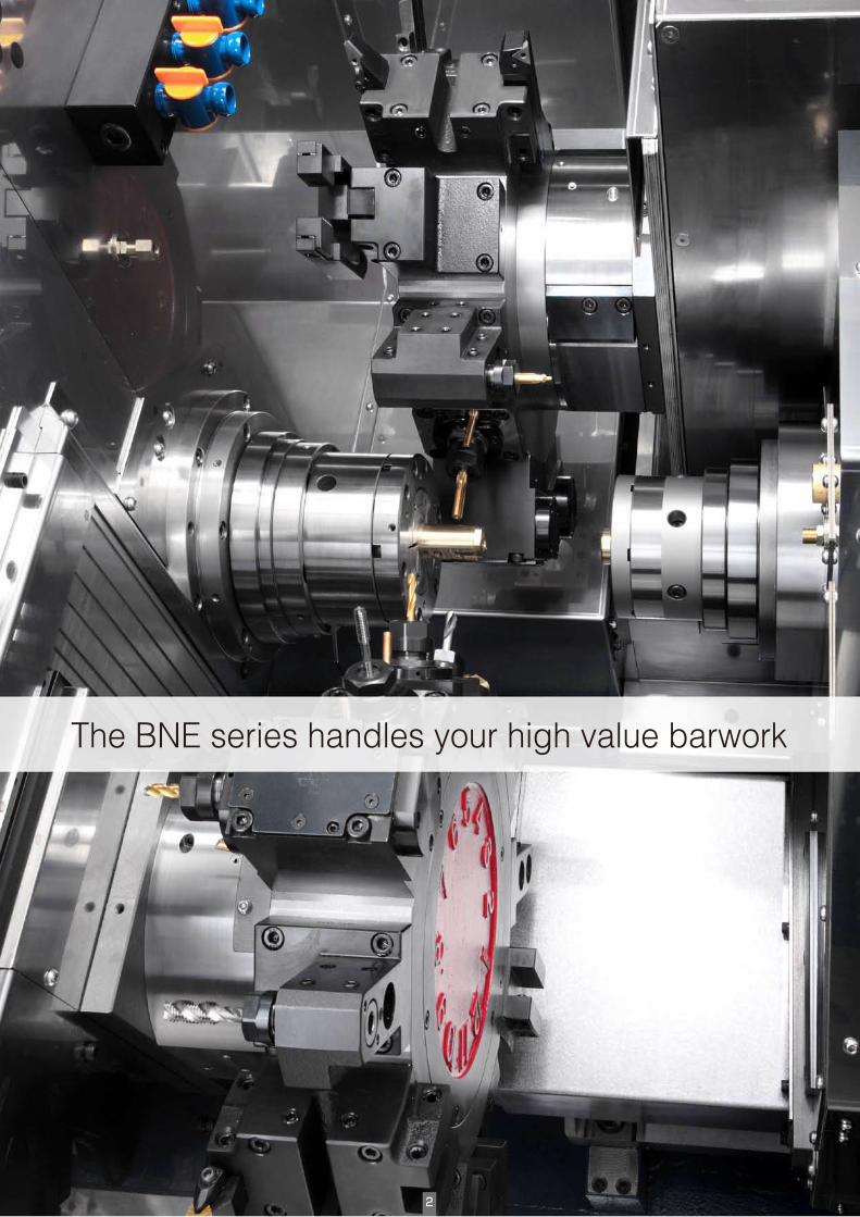
The BNE series handles your high value barwork
2

CNC Turning Center with 2 Spindles, 2 Turrets
BNE-34S5 / BNE-51S5
CNC Turning Center with 2 Spindles, 2 Turrets and 1 Y-axis Slide
BNE-34SY5 / BNE-51SY5
The BNE Series was designed to handle today's ever demanding high efficiency barwork.
Operating multiple tools simultaneously, parts with more complex functions can now be
produced with higher level of efficiency. The S-Type features simultaneous multiple tooling on
the L/R spindles.
The "SY" type with Y-Axis slide for the upper turret has the capability of a machining center to
handle more complex workpieces. The new design of the 2-types feature easies programming
and machine operation to reduce set-up times.
3

4
Simultaneous Machining To Eliminate Second Operations.Completes machining made faster by L/R spindles, U/L Turrets, and C/Y-Axis.
The 2-machine-in-one, 2-spindle/2-Turret design combines all processing within a single machine. This will elliminate the secondary operation and the time loss by part-handling to achieve optimim efficiency.
Build Your IT System By Ethernet Connection.Ethernet helps manage the programs and monitor the machine operation.
FANUC Series i NC allows you to connect multiple BNE models to your PCs to manage your programs and monitor the machine operation. Total machine management solutions are provided.
Powerful, Combined Machining Saves Time.High-power/speed balanced turning and differential cutting boost efficiency.。
"Balance turning", sumultaneous turning by the upper/lower turret, and differential cutting will further reduce the cycle time.
Costs Reduced By Unmanned OperationBar material to finished parts by automatic magazine barfeeder and parts stocker. Tremendous cost saving can be achieved by using magazine loaded automatic barfeeder, part catcher, and parts stocker. Please see page 6 for details.
BNE-34SY5・51SY5Machine Schema
Models And Features Optimized For Your Needs.Select the models and the options to build a system optimized for your needs.
S type featues complete, single-setup machining with L/R spindles, C-Axis and live tools. SY-Type features more sophisticated combined machining with Y-Axis slide. Method of the Y-Axis programming is common with all SY models.
5
Machining Examples
C-Axis Machining
Y-Axis Machining
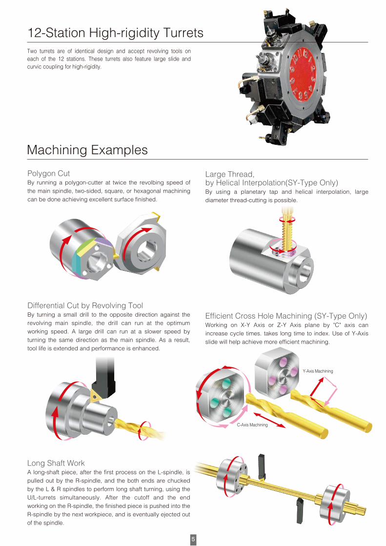
Two turrets are of identical design and accept revolving tools on each of the 12 stations. These turrets also feature large slide and curvic coupling for high-rigidity.
12-Station High-rigidity Turrets
Polygon Cut By running a polygon-cutter at twice the revolbing speed of the main spindle, two-sided, square, or hexagonal machining can be done achieving excellent surface finished.
Differential Cut by Revolving ToolBy turning a small drill to the opposite direction against the revolving main spindle, the drill can run at the optimum working speed. A large drill can run at a slower speed by turning the same direction as the main spindle. As a result, tool life is extended and performance is enhanced.
Large Thread, by Helical Interpolation(SY-Type Only)By using a planetary tap and helical interpolation, large diameter thread-cutting is possible.
Efficient Cross Hole Machining (SY-Type Only)Working on X-Y Axis or Z-Y Axis plane by "C" axis can increase cycle times. takes long time to index. Use of Y-Axis slide will help achieve more efficient machining.
Long Shaft WorkA long-shaft piece, after the first process on the L-spindle, is pulled out by the R-spindle, and the both ends are chucked by the L & R spindles to perform long shaft turning, using the U/L-turrets simultaneously. After the cutoff and the end working on the R-spindle, the finished piece is pushed into the R-spindle by the next workpiece, and is eventually ejected out of the spindle.

6
L-Sp. Rev. R-Sp. Syncro Rev.Cut-off Tool
Cu-toff Position
R-Sp. Back Travel
Specifies position for cutoff confirmation and program skip.
Back travel under low sliding force for cut-off confirmation.
突切確認
Chip ConveyerThe device promptly transferrs chips
to the outside of the machine.
Basic options for barwoking system includes automatic bar feeder, cutoff confirmation device, parts catcher and parts conveyor. Additionally, a parts stocker with tray changer which arranges the parts on the tray in an upright position in neat order, as well as an automatic measuring device forms a complete hands-free system from raw material to finished parts.This helps to achieve an efficient work-flow and elliminates work in progress, Just-in-time.
Magazine Loaded Automatic Bar Feeder A key item to achieve long hours of barwork operation
Automatic Measuring DeviceBy placing inside or outside the machine,
the device performs automatic geometry offset.
Automatic Barfeeder
Main Spindle
Sub Spindle
Shuttle Conveyor
Part Catcher
Robotic Parts Stocker
Tray Changer
Cutoff Confirmation
Labor-Saving Continuous Operating System (Simulated Drawing)
Cutoff Confirmation SystemThis function confirms by program that the
R-spindle can retract with a small amount
of thrust command position for the cutoff
confirmation and physical interfernce or
machanical breakdown.
Parts Stocker with Pallet ChangerThe workpiece received from the
part catcher is placed in order onto
a pallet through a shuttle conveyer.
When it's full, the pallet is exchanged
automatically.
MS JetThe high-pressure coolant
at 6 Mpa extends tool life
and forces out the cutting
chips.
Part Catcher & PartsConveyer
Standard bucket-type part catcher
receives the workpiece and places it
on parts conveyer to carry it to the
outside of the machine.
A Variety of Options to Meet Your Needs
System to Save Labor

7
L-Sp. Rev. R-Sp. Syncro Rev.Cut-off Tool
Cu-toff Position
R-Sp. Back Travel
Specifies position for cutoff confirmation and program skip.
Back travel under low sliding force for cut-off confirmation.
MACHINE SPECIFICATIONS
NC SPECIFICATIONS MIYANO - FANUC
Items Model Name BNE-34S5 BNE-51S5 BNE-34SY5 BNE-51SY5
Machining Capacity & Chuck SystemMax. Bar Capacity L/R Spindle φ34/φ34mm φ51/φ42mm φ34/φ34mm φ51/φ42mm
(1.34"D/1.34"D) (2.0"D/1.6"D) (1.34"D/1.34"D) (2.0"D/1.61"D)
Max. Turning Length 90mm(3.54") 90mm(3.54") 90mm(3.54") 90mm(3.54")
Power Chuck & Size� L/R Spindle 5"/5" Oil Hyd. 6"/5" Oil Hyd. 5"/5" Oil Hyd. 6"/5" Oil Hyd.
SpindleType of Cllet Chuck Stationary Stationary Stationary Stationary
Spindle Speed Range L Spindle 70~7,000min-1 50~5,000min-1 70~7,000min-1 50~5,000min-1
R Spindle 50~5,000min-1 50~5,000min-1 50~5,000min-1 50~5,000min-1
Spindle Motor L/R Spindle(30min. rat) 7.5/5.5kW 15/5.5kW 7.5/5.5kW 15/5.5kW
R Spindle Slide Travel (B Axis) 450mm(17.72") 450mm(17.72") 450mm(17.72") 450mm(17.72")
TurretType of Turret Upper/Lower Turret 12St./12St. Turret 12St./12St. Turret 12St./12St. Turret 12St./12St. Turret
Type of Y Axis Slide ……… ……… Orthogonal Slide Orthogonal Slide
Tool Shunk Size Upper & Lower Turret �20mm(3/4" Sq.) �20mm(3/4" Sq.) �20mm(3/4" Sq.) �20mm(3/4" Sq.)
Tool Hole Dia. Upper & Lower Turret φ25mm(1" Dia.) φ25mm(1" Dia.) φ25mm(1" Dia.) φ25mm (1" Dia.)
Upper Turret Slide Travel X1 Axis Slide 175mm(6.9") 175mm(6.9") 175mm(6.9") 175mm(6.9")
Z1 Axis Slide 380mm(14.97") 380mm(14.97") 380mm(14.97") 380mm(14.97")
Y Axis Slide ……… ……… ±40mm(±1.58") ±40mm(±1.58")
Lower Turret Slide Travel X2 Axis Slide 145mm(5.7") 145mm(5.7") 145mm(5.7") 145mm(5.7")
Z2 Axis Slide 175mm(6.9") 175mm(6.9") 175mm(6.9") 175mm(6.9")
Turret Indexing Time Upper/Lower Turret 0.25/0.25sec./pos 0.25/0.25sec./pos 0.25/0.25sec./pos 0.25/0.25sec./pos
Revolving tools No. of Revolving Tool St. Upper/Lower Turret 12/12 12/12 12/12 12/12
Revolving Tool Speed Range Upper/Lower Turret 60~6,000min-1 60~6,000min-1 60~6,000min-1 60~6,000min-1
Drilling Capacity Upper & Lower Turret φ16mm(0.5" D) φ16mm(0.5" D) φ16mm(0.5" D) φ16mm(0.5" D)
Tapping Capacity Upper & Lower Turret M12(5/16-22UN) M12(5/16-22UN) M12(5/16-22UN) M12(5/16-22UN)
Driving Motor Cont/Short Rat. Upper & Lower Turret 2.2/ 8.3kW 2.2/ 8.3kW 2.2/ 8.3kW 2.2/ 8.3kW
Coolant Tank Capacity 350L 350L 350L 350L
Machine DimensionsMachine Hight 1,895mm(74.6") 1,895mm(74.6") 2,080mm(81.9") 2,080mm(81.9")
Hight of Spindle Center 1,200mm(47.2") 1,200mm(47.2") 1,200mm(47.2") 1,200mm(47.2")
Floor Space 2,690×2,080mm 2,690×2,080mm 2,690×2,080mm 2,690×2,080mm
(105.9"×81.9") (105.9"×81.9") (105.9"×81.9") (105.9"×81.9")
Machine Weight 7,080kg(15,610"Lbs.) 7,080kg(15,610"Lbs.) 7,380kg(16,270"Lbs.) 7,430kg(16,380"Lbs.)
Others Splash Guard Interlock, Coolant, Pneumatic Unit, Machine Light
OptionsCollet Chuck System, Power Chuck System, Cut-off Confirmation, R Spindle Through Coolant & Work Ejector, Air Blow, High Pressure Coolant,
Coolant Level Switch, Revolving Tools & Driving Unit, Parts Catcher & Parts Conveyor, Auto Door,
Automatic Power Off, Chip Conveyor, Signal Tower (3 Steps), Magazine Bar Feeder.
Note. The specifications are subject to change without notice. Standard equipment package may vary by region. Machine in photo. may not look exactly the same as the actual products.
�Simultaneous control axis 4/3 Axes: 2 System (X1, Z1, X2, Z2, B, Cs1, Cs2-axis) … S Type
5/4 Axes: 2 System (X1, Z1, Y1, A1, X2, Z2, Y2, A2, Cs1, Cs2-axis) … SY Type�Min. input increment 0.001mm, 0.0001inch, 0.001degree�Min. output resolution X-axis: 0.0005mm, Z-axis: 0.001mm, Cs-axis:0.01deg., Y-axis:0.001mm�Parts program storage capacity 64kB (160m tape length), 120 Programs�Spindle function Spindle speed S5 digits direct specify (G97),
Constant cutting speed control (G96),�Cutting feed rate F3.4 digit direct specify(feed per rev. : mm/rev., feed per min. : mm/min.)�Cutting feed rate override 0~150% (10steps)�Interpolation G01, G02, G03�Threading G32, G33 (SY-type), G92�Canned cycle G90, G92, G94�Work coordinate setting Automatic setting, 32 sets by the geometry offset function per each system.�Tool selection and work coordinate Tool and work coordinate system selection 1~32 can be done by
system selection the first two digit of the T-4 digit code.�Tool wear offset Tool wear offset selection Last two digit of the T-4 digit code.�Direct input of the tool position Measured value can be directly key in.�Manual pulse generator 0.001mm/1pulse (×1 ×10 ×100 selection)�Automatic operation 1 cycle operation/Continuous operation, Single block operation,
Block delete, Machine lock, Optional block skip [/], Dry run. Feed hold.�Others
10.4" color LCD, Decimal point input, Memory protect, Cs-axis control (L/R Spindle),
Synchronous mixed control, Polar coordinate interpolation,
AC digital servo, Machine alarm display, Absolute position coder,
I/O interface (RS-232C, PC card slot)�NC Options
Chamfering/Corner R, Tool nose R compensation, Multi-repetitive canned cycle (G70~G76),
Drilling canned cycle (G80~G86), Run hour/Parts number countering, Background editing,
Additional tool wear off-set (Total : 64 pairs), Additional parts program storage (Total : 320m, 640m, 1,280m,
2,560m), Programmable data input (G10), Tool life management system, Retrace Function on a tool path,
Custom Macro B, Cylindrical interpolation ( for Cs-axis), Continuous multi-lead thread cutting,
Variable lead threading, Rigid tapping function at L/R-spindle/Revolving tools ( Include drilling canned cycle) ,
Helical interpolation, Polygon Turning function, Direct drawing dimension input, Superpose feed function A
NC Operation Panel
Data I/O with laptop PC

EXTERNAL VIEW
CNC Turning Center with 2 Spindles, 2 Turrets and 1 Y-axis Slide
BNE-34S5/51S5
883 175
630
1.020
1,200
695
1,925
1,865 475 1,505 400
2,690 2,080
350
BNE-34SY5/51SY5
883 175
630
1.020
185
1,200
695
2,080
1,865 475 1,505 400
2,690 2,080
350
PRINTED IN JAPAN 2011.Aug 7-10-20AO