cnc cooltool - milling machine - pbworksstsdubai.pbworks.com/w/file/fetch/92339586/module 1 term 2...
TRANSCRIPT
1 Prepared By: Tareq Al Sawafta
CNC Cooltool - Milling Machine
Module 1:
Introduction to CNC Machining
2 Prepared By: Tareq Al Sawafta
Module Objectives:
1. Define machining.
2. Know the milling machine parts
3. Understand safety rules in machining
4. Distinguish between machining cutting tools.
5. Recognize the main machining processes.
Module Contents
1. General Introduction and Definitions
2. Description of Milling Machines
3. Safety precautions on CNC machine tools
4. Types of milling tools
5. Milling operations

3 Prepared By: Tareq Al Sawafta
1.1 General Introduction and Definitions
Machining is a class of material-working processes that involves using a power-
driven machine tool to shape metal.
The parts shown in Fig.1.1 are made by machining processes.
Fig. 1.1
The two major categories of machining are:
1. Conventional machining.
Also known as "manual machining" is generally regarded as using manually
controlled machines, particularly lathes, mills and drill presses. The tool
moves around the work by mechanical controls that are manually controlled.
2. CNC (computer numerical control) machining.
CNC machining is generally regarded as using lathes and mills (and some
other machine types) in which all tool and workpiece motion is controlled by
a computer.
The actual metal cutting process is the same. The difference is in how the
tool path is controlled as it cuts the workpiece.

4 Prepared By: Tareq Al Sawafta
1.1.1: History and Development of CNC Technology
The idea of numerical control (NC) of machine tools emerged in 1949/50 at
the MIT (Massachusetts Institute of Technology, Cambridge, USA) in order to
manufacture important airplane parts from full material rather than by
riveting and welding material together.
The templates and patterns needed for form cutting were however very
complicated and could only be manufactured with a considerable time and
cost increase when using conventional technology. Since how-ever the
contours of the large parts could easily be represented as mathematical
functions it was decided to develop a control to control a milling machine on
this basis.
1.1.2: What is CNC?
CNC stands for Computer Numerical Control. It is the technology of
controlling a machining operation using a computer program, which is called
Numerical Control (NC) Program. Fig. 1.1.2
Fig. 1.1.2

5 Prepared By: Tareq Al Sawafta
1.2: Description of Milling Machines
The most important conventional machine tools that shape materials
to a size by cutting away unwanted portions, are:
a. Turning (Lathe) machine
The primarily function, of the turning machine is to produce a cylindrical
surfaces.
b. Milling machine.
Use a rotating multi toothed cutter into the workpiece to remove material, in
order to make gears, slots, holes, many different shapes.
1.2.1: Milling machines are classified to:
a. Vertical milling machine
in which the spindle positioned perpendicular
to its worktable.

6 Prepared By: Tareq Al Sawafta
CNC Cooltool vertical milling machine parts

7 Prepared By: Tareq Al Sawafta
b. Horizontal milling machine shown in Fig.
in which the cutting tool positioned horizontally and parallel to the
worktable.
1.3: Safety precautions on CNC machines
The target of work security is to eliminate accidents and damages to
persons, machines and facilities at work site.
Basically the same work security precautions apply to working on CNC
machines as to conventional machine tools. They can be classified in three
categories:
1. Danger elimination
Defects on machines and on all devices necessary for work need to be
registered at once.
Emergency exits have to be kept free.
No sharp objects should be carried in clothing.
Watches and rings are to be taken off.

8 Prepared By: Tareq Al Sawafta
2. Screening and marking risky areas:
The safety precautions and corresponding notifications are not allowed to be
removed or inactivated. Moving and intersecting parts must be screened.
3. Eliminating danger exposure
Protective clothing must be worn to protect from possible sparks and
flashes.
Protective glasses or protective shields must be worn to protect the eyes.
Damaged electrical cables are not allowed to be used.
When setting up and operating CNC machines the following is to be taken
into consideration:
• In general, setting-up is allowed only on a machine which has been
switched off.
• The operator should not go to the rotation or work area of the machine
since within this area the machine can automatically rotate the turret head
or feed the tool carrier.
ATTENTION
Milling can be very dangerous, you can be seriously injured !
AVOID
Wrong milling direction (always mill against the turning direction of the
milling head), too thick chips.
The surface of the work piece is not clean
Mill again, less feed, check milling direction
Machine does not work exactly
Check connections, clean and grease slides (they must be easily moveable),
check backlash.
Backlash is the play in the engagement of the spindles for cross and
longitudinal
slide that allows a few hundreds of a mm to be turned on the
handwheel before the leadscrew starts to turn when changing directions.
9 Prepared By: Tareq Al Sawafta
This is not a fault with the machine but simply a fact of life on any threaded
screw and is accounted for by always making your cuts in the same
direction and keeping track of which way you turned the handwheel last.
We recommend backlash be set to about 0,08 mm to 0,12 mm. Unimat
slides come with adjustable handwheels to recalibrate on change of
direction.
Finishing steps:
1. Shut off the machine.
2. Switch off the power supply.
3. Use a brush to remove chips from the work piece
4. Keep workplace clean and tidy.
1.4: Classifications of milling tools
Details of milling tools are given in the manufacturers´ catalogues and in the
corresponding norm sheets.
1.4.1: Cutting edge materials
In milling, the cutting edges are not in operation all the time. The milling cut
is a discontinuous cut with a changing cutting diameter. Therefore, the
cutting edge is exposed to high impact forces. The cutting edge material has
to be tough and heat resistant, and they are:
1. High-speed steel
2. Hard metals
3. Cutting ceramics
4. Diamond
10 Prepared By: Tareq Al Sawafta
1.4.2: Cutting oils (coolant)
The major advantage of using a coolant or cutting oil is:
1. It dissipates heat
2. giving longer life to the cutting edges
3. Lubricates the cutter face
4. Flushes away the chips
Types
Cutting oils are:
1. Water-based soluble oils,
2. Petroleum oils
3. Synthetic oils.
In general, a simple coolant is required for roughing. Finishing
with good lubricating properties to help produce a good finish on the
workpiece. Plastics and cast iron are almost always machined dry.
11 Prepared By: Tareq Al Sawafta
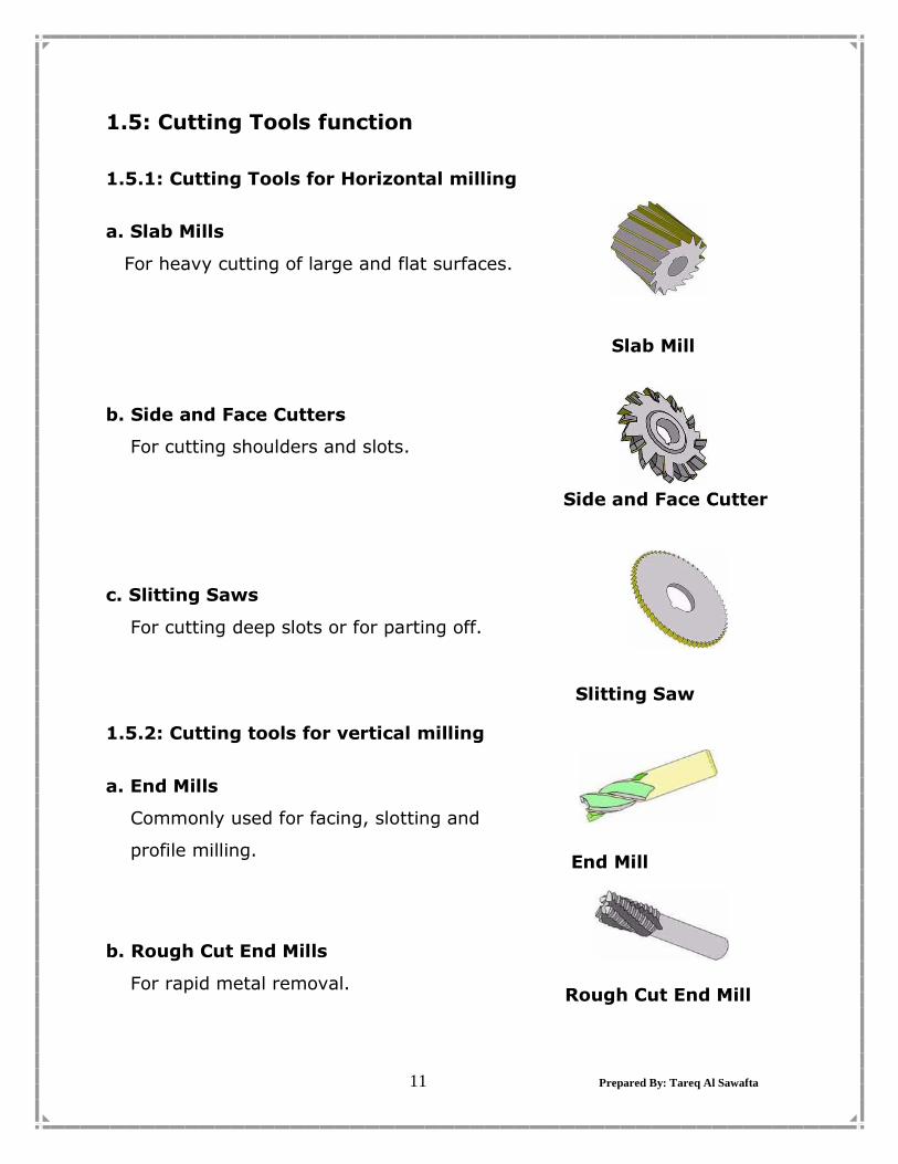
1.5: Cutting Tools function
1.5.1: Cutting Tools for Horizontal milling
a. Slab Mills
For heavy cutting of large and flat surfaces.
Slab Mill
b. Side and Face Cutters
For cutting shoulders and slots.
Side and Face Cutter
c. Slitting Saws
For cutting deep slots or for parting off.
Slitting Saw
1.5.2: Cutting tools for vertical milling
a. End Mills
Commonly used for facing, slotting and
profile milling.
End Mill
b. Rough Cut End Mills
For rapid metal removal.
Rough Cut End Mill
12 Prepared By: Tareq Al Sawafta
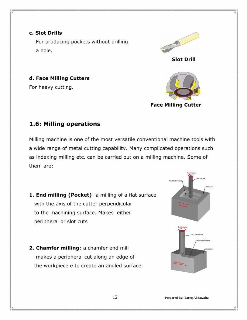
c. Slot Drills
For producing pockets without drilling
a hole.
Slot Drill
d. Face Milling Cutters
For heavy cutting.
Face Milling Cutter
1.6: Milling operations
Milling machine is one of the most versatile conventional machine tools with
a wide range of metal cutting capability. Many complicated operations such
as indexing milling etc. can be carried out on a milling machine. Some of
them are:
1. End milling (Pocket): a milling of a flat surface
with the axis of the cutter perpendicular
to the machining surface. Makes either
peripheral or slot cuts
2. Chamfer milling: a chamfer end mill
makes a peripheral cut along an edge of
the workpiece e to create an angled surface.

13 Prepared By: Tareq Al Sawafta
3. Face milling: a face mill machines a
flat surface of the workpiece in order to
provide a smooth finish.
4. Drilling: a drill enters the workpiece
axially and cuts a hole with a diameter
equal to that of the tool.
5. Boring:
performed after drilling a hole to
enlarge the diameter or obtain
more precise dimensions.
6. Tapping:
The existing hole is typically drilled
By the required tap drill size that will
accommodate the desired tap.
14 Prepared By: Tareq Al Sawafta
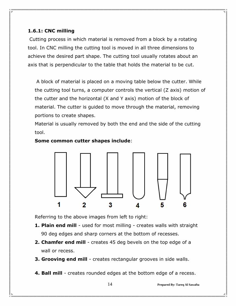
1.6.1: CNC milling
Cutting process in which material is removed from a block by a rotating
tool. In CNC milling the cutting tool is moved in all three dimensions to
achieve the desired part shape. The cutting tool usually rotates about an
axis that is perpendicular to the table that holds the material to be cut.
A block of material is placed on a moving table below the cutter. While
the cutting tool turns, a computer controls the vertical (Z axis) motion of
the cutter and the horizontal (X and Y axis) motion of the block of
material. The cutter is guided to move through the material, removing
portions to create shapes.
Material is usually removed by both the end and the side of the cutting
tool.
Some common cutter shapes include:
Referring to the above images from left to right:
1. Plain end mill - used for most milling - creates walls with straight
90 deg edges and sharp corners at the bottom of recesses.
2. Chamfer end mill - creates 45 deg bevels on the top edge of a
wall or recess.
3. Grooving end mill - creates rectangular grooves in side walls.
4. Ball mill - creates rounded edges at the bottom edge of a recess.
15 Prepared By: Tareq Al Sawafta
5. Rounding end mill - creates rounded edges at the top edge.
6. Angle end mill - creates walls at angles other than 90 deg.

16 Prepared By: Tareq Al Sawafta
Student's Notes
…………………………………………………………………………….……………………… …………………………………………………………………..…………………………….…
………………………………………………………………………………………….………… ……………………………………………………………………………..…….………………
………………………………………………… ……….………………………………….……
………………………………………………………………………………………………….… ……………………………………………………………………………………………….…… ……………………………………………………………………………………….………..…
…………………………………………………………………………………………….……… ………………………………………………………………………………………………….… ………………………………………………………………………………………………….…
…………………………………………………………………………………………………... ……………………………………………………………………………………………….…… ……………………………………………………………………………………………….…..
……………………………………………………………………………………………...…… ………………………………………………………………………………………………...… ……………………………………………………………………………………………….……
…………………………………………………………………………………………..…….…
17 Prepared By: Tareq Al Sawafta
Student's Notes
…………………………………………………………………………….……………………… …………………………………………………………………..…………………………….…
………………………………………………………………………………………….………… ……………………………………………………………………………..…….………………
………………………………………………… ……….………………………………….……
………………………………………………………………………………………………….… ……………………………………………………………………………………………….…… ……………………………………………………………………………………….………..…
…………………………………………………………………………………………….……… ………………………………………………………………………………………………….… ………………………………………………………………………………………………….…
…………………………………………………………………………………………………... ……………………………………………………………………………………………….…… ……………………………………………………………………………………………….…..
……………………………………………………………………………………………...…… ………………………………………………………………………………………………...… ……………………………………………………………………………………………….……
…………………………………………………………………………………………..…….…

18 Prepared By: Tareq Al Sawafta
Student's Notes
…………………………………………………………………………….……………………… …………………………………………………………………..…………………………….…
………………………………………………………………………………………….………… ……………………………………………………………………………..…….………………
………………………………………………… ……….………………………………….……
………………………………………………………………………………………………….… ……………………………………………………………………………………………….…… ……………………………………………………………………………………….………..…
…………………………………………………………………………………………….……… ………………………………………………………………………………………………….… ………………………………………………………………………………………………….…
…………………………………………………………………………………………………... ……………………………………………………………………………………………….…… ……………………………………………………………………………………………….…..
……………………………………………………………………………………………...…… ………………………………………………………………………………………………...… ……………………………………………………………………………………………….……
…………………………………………………………………………………………..…….…