cnc back planes 48.01.00xx - sieb & meyer · cnc back planes 48.01.00xx.x cnc back planes...
TRANSCRIPT

� CNC Back Planes 48.01.00xx.x
CNC Back Planes 48.01.00xx.x - 1 -
CNC Back Planes . . . . . . . . . . . . . . . . . . . . . . . . . . . . . . . . . . . . . . . . . . . . . . . 248.01.0002.x . . . . . . . . . . . . . . . . . . . . . . . . . . . . . . . . . . . . . . . . . . . . . . . . . . . . 248.01.0003.x . . . . . . . . . . . . . . . . . . . . . . . . . . . . . . . . . . . . . . . . . . . . . . . . . . . . 448.01.0009.x . . . . . . . . . . . . . . . . . . . . . . . . . . . . . . . . . . . . . . . . . . . . . . . . . . . . 648.01.0010.x . . . . . . . . . . . . . . . . . . . . . . . . . . . . . . . . . . . . . . . . . . . . . . . . . . . . 848.01.0013.x . . . . . . . . . . . . . . . . . . . . . . . . . . . . . . . . . . . . . . . . . . . . . . . . . . . 1048.01.0014.x . . . . . . . . . . . . . . . . . . . . . . . . . . . . . . . . . . . . . . . . . . . . . . . . . . . 1248.01.0016.x . . . . . . . . . . . . . . . . . . . . . . . . . . . . . . . . . . . . . . . . . . . . . . . . . . . 14
Cables and Connectors . . . . . . . . . . . . . . . . . . . . . . . . . . . . . . . . . . . . . . . . . 16Cable 1 - Universal Serial Bus . . . . . . . . . . . . . . . . . . . . . . . . . . . . . . . . . . . . . 1650.20.0002 - Voltage Supply of the PC . . . . . . . . . . . . . . . . . . . . . . . . . . . . . . . 17Connector 2 and 3 - DC Voltage Supply of the PC . . . . . . . . . . . . . . . . . . . . . . 17Cable 5 - DC Voltage Supply . . . . . . . . . . . . . . . . . . . . . . . . . . . . . . . . . . . . . . 18Cable 9A - Serial Data for In- and Outputs . . . . . . . . . . . . . . . . . . . . . . . . . . . . 18Cable 9C - SERVOLINK . . . . . . . . . . . . . . . . . . . . . . . . . . . . . . . . . . . . . . . . . . 19Cable 12 - VGA Monitor . . . . . . . . . . . . . . . . . . . . . . . . . . . . . . . . . . . . . . . . . . 19Cable 13 to 16 - COM Interfaces . . . . . . . . . . . . . . . . . . . . . . . . . . . . . . . . . . . 20Cable 17 / Cable 18 - SM Net . . . . . . . . . . . . . . . . . . . . . . . . . . . . . . . . . . . . . . 21Cable 28 - Handwheels / Differential Measuring Systems . . . . . . . . . . . . . . . . 22Cable 33 - ETHERNET Connection . . . . . . . . . . . . . . . . . . . . . . . . . . . . . . . . . 22Cable 33A - ETHERNET Connection . . . . . . . . . . . . . . . . . . . . . . . . . . . . . . . . 22Cable 34 - TFT Flat Panel . . . . . . . . . . . . . . . . . . . . . . . . . . . . . . . . . . . . . . . . 23Cable 34A - TFT Flat Panel . . . . . . . . . . . . . . . . . . . . . . . . . . . . . . . . . . . . . . . 24Cable 35 - PC Keyboard . . . . . . . . . . . . . . . . . . . . . . . . . . . . . . . . . . . . . . . . . . 24Cable 35H - PC-Keyboard (PS/2) . . . . . . . . . . . . . . . . . . . . . . . . . . . . . . . . . . . 24Cable 35B - CNC Keyboard . . . . . . . . . . . . . . . . . . . . . . . . . . . . . . . . . . . . . . . 25Cable 36 / Cable 37 - LPT Interfaces . . . . . . . . . . . . . . . . . . . . . . . . . . . . . . . . 25Cable 38 - Illumination for TFT Flat Panel . . . . . . . . . . . . . . . . . . . . . . . . . . . . 26Cable 39 - PC Reset . . . . . . . . . . . . . . . . . . . . . . . . . . . . . . . . . . . . . . . . . . . . . 26Cable 42B - Machine Connection . . . . . . . . . . . . . . . . . . . . . . . . . . . . . . . . . . . 26Cable 58 - External Enable for Differential Measuring . . . . . . . . . . . . . . . . . . . 27Cable 71 to 76 - Differential Measuring Systems . . . . . . . . . . . . . . . . . . . . . . . 28Connector 97 - Service Switch . . . . . . . . . . . . . . . . . . . . . . . . . . . . . . . . . . . . . 28

�CNC Back Planes 48.01.00xx.x
- 2 - CNC Back Planes 48.01.00xx.x
CNC Back Planes
48.01.0002.xBack plane (25 WU) for CNC 48.00 with integrated PC and depth-controlled dril-ling/routing for up to 2 Z axes
Back plane 48.01.0002.x combined with CPU 48.01.1x allows depth-controlled dril-ling/routing for up to 2 Z axes. If the system is provided with depth-controlled dril-ling/routing for 2 Z axes, the measuring systems DZ1 and DZ2 are connected to thefemale connectors 28X and 28Y.
1 universal serial bus
9A I/O Link
9C SERVOLINK
12 VGA monitor
13-16 COM interfaces
28X/28Y handwheels X/Y or differential measu-ring systems*
33 Ethernet (BNC connector)*
33A Ethernet (RJ45 connector)*
34/34A TFT flat panel*
35/35H PC keyboard
36 LPT interface LPT1
37LPT interface LPT2connection possibility of a deactivationcon t ro l f o r the CNC, modu le50.01.0020.x
42B machine connection via module48.20.0001.x
58 external enable for differential measu-ring*
U,V,W voltage supply for the CNC power mo-dule 48.01.4
N GND
�*Consider further information referring the connectors on the backplane (see next page).

� CNC Back Planes 48.01.00xx.x
CNC Back Planes 48.01.00xx.x - 3 -
Information on the Connectors on Back Plane 48.01.0002.x
� 28X/28YMachines which are to be provided with both functions (handwheels and differen-tial measuring systems) must be equipped with module 48.20.0002.x.
� 33/33ASince the driver on the PC card by SIEB & MEYER does not support the BNCconnector, it is not mounted on the CNC back plane from version 48.01.0002.1on. When using this PC card, the Ethernet connection must always be realizedvia connector 33A. However, the slot which is provided on the back plane for aBNC connector can be mounted optionally.
� 34/34AFrom version 48.01.0002.1 on, this slot is provided on the back plane as 15-polefemale submin D connector and is mounted optionally. A TFT flat panel is con-nected via cable 34A. On former versions of the back plane, the slot is conceivedas 34-pole flat cable connector. In this case, cable 34 must be used for connec-ting a TFT flat panel.
� 35/35HThe back plane is equipped with a 5-pole 180� DIN connector. A PC keyboard isconnected via cable 35. PC keyboards with 6-pole DIN connectors (PS/2) areconnected via an appropriate adapter and cable 35H.
� 38The connector for the illumination of a TFT flat panel is provided as 2-polePHOENIX connector on the PC back plane and can be mounted optionally.
� *58Using the function external enable for differential measuring (from PCB version48.01.0002.2 on) will only be possible, if the DZ module 48.01.15x and the CPU48.01.7C or 48.01.7D are provided.
�Consider also special information referring the pin assignment of con-nector 58 when different numbers of Z axes are connected.

�CNC Back Planes 48.01.00xx.x
- 4 - CNC Back Planes 48.01.00xx.x
48.01.0003.xBack plane (12 WU) for CNC 48.00 with connecting possibility for external PCand depth-controlled drilling/routing for up to 2 axes
Back plane 48.01.0003.x combined with CPU 48.01.1x allows depth-controlled dril-ling/routing for up to 2 Z axes. If the system is provided with depth-controlled dril-ling/routing for 2 Z axes, the measuring systems DZ1 and DZ2 are connected to thefemale connectors 28X and 28Y.
1 universal serial bus
2/3 voltage supply of the PC via plug-in board 50.20.0002.x
9A I/O Link
9C SERVOLINK
17/18 SM Net, connection of external PC
28X/28Y handwheels X/Y or differential measuring systems*
35B SM keyboard
42B machine via module 48.20.0001.x
58 external enable for differential measuring*
97 service switch*If the switch is open, the HDLC connection is interrupted.
U, V, W voltage supply for the CNC power module 48.01.4
N GND
�*Consider further information referring the connectors on the backplane (see next page).

� CNC Back Planes 48.01.00xx.x
CNC Back Planes 48.01.00xx.x - 5 -
Information on the Connectors on Back Plane 48.01.0003.x
� 28X/28YMachines which are to be provided with both functions (handwheels and differen-tial measuring systems) must be equipped with module 48.20.0002.x.
� 58Using the function external enable for differential measuring (from PCB version48.01.0003.3 on) will only be possible, if the DZ module 48.01.15x combined withthe CPU 48.01.7C or 48.01.7D are provided.
�Consider also special information referring the pin assignment of con-nector 58 when different numbers of Z axes are connected.
� 97The service switch for interrupting the HDLC connection is mounted on the backplane from version 48.01.0003.2 on.

�CNC Back Planes 48.01.00xx.x
- 6 - CNC Back Planes 48.01.00xx.x
48.01.0009.xBack plane (14 WU) for CNC 48.00 with connecting possibility for an externalPC and depth-controlled drilling/routing for up to 8 Z axes
Depth-controlled drilling/routing for up to 2 Z axesBack plane 48.01.0009.x combined with CPU 48.01.1x allows depth-controlled dril-ling/routing for 2 Z axes at maximum. If the system is provided with depth-controlleddrilling/routing for 2 Z axes, the measuring systems DZ1 and DZ2 are connected tothe female connectors 28X and 28Y. In this case, the female connectors 71 to 76have no function.
Depth-controlled drilling/routing for up to 8 Z axesBack plane 48.01.0009.x combined with CPU 48.01.7x and module 48.01.8x or48.01.15x* allows depth-controlled drilling/routing for up to 8 Z axes. The inputs forthe differential measuring systems DZ1 to DZ6 are the female connectors 71 to 76and for DZ7 and DZ8 the female connectors 28X and 28Y.
1 universal serial bus
9A I/O Link
9C SERVOLINK
17/18 SM Net, connection of external PC
28X/28Y handwheels X/Y or differential measuring systems*
35B SM keyboard
42B machine via module 48.20.0001.x
58 external enable for differential measuring*
71-76 differential measuring system DZ1 to DZ6
97service switch*If the switch is open, the HDLC connection is inter-rupted.
U, V, W voltage supply for the CNC power module 48.01.4
N GND
�*Consider further information referring the connectors on the backplane (see next page).

� CNC Back Planes 48.01.00xx.x
CNC Back Planes 48.01.00xx.x - 7 -
Information on the Connectors on Back Plane 48.01.0009.x
� 28X/28YMachines which are to be provided with both functions (handwheels and differen-tial measuring systems) must be equipped with module 48.20.0002.x.
� 58Using the function external enable for differential measuring (from PCB version48.01.0009.2 on) will only be possible, if the DZ module 48.01.15x and the CPU48.01.7C or 48.01.7D are provided.
�Consider also special information referring the pin assignment of con-nector 58 when different numbers of Z axes are connected.
�CNC Back Planes 48.01.00xx.x
- 8 - CNC Back Planes 48.01.00xx.x
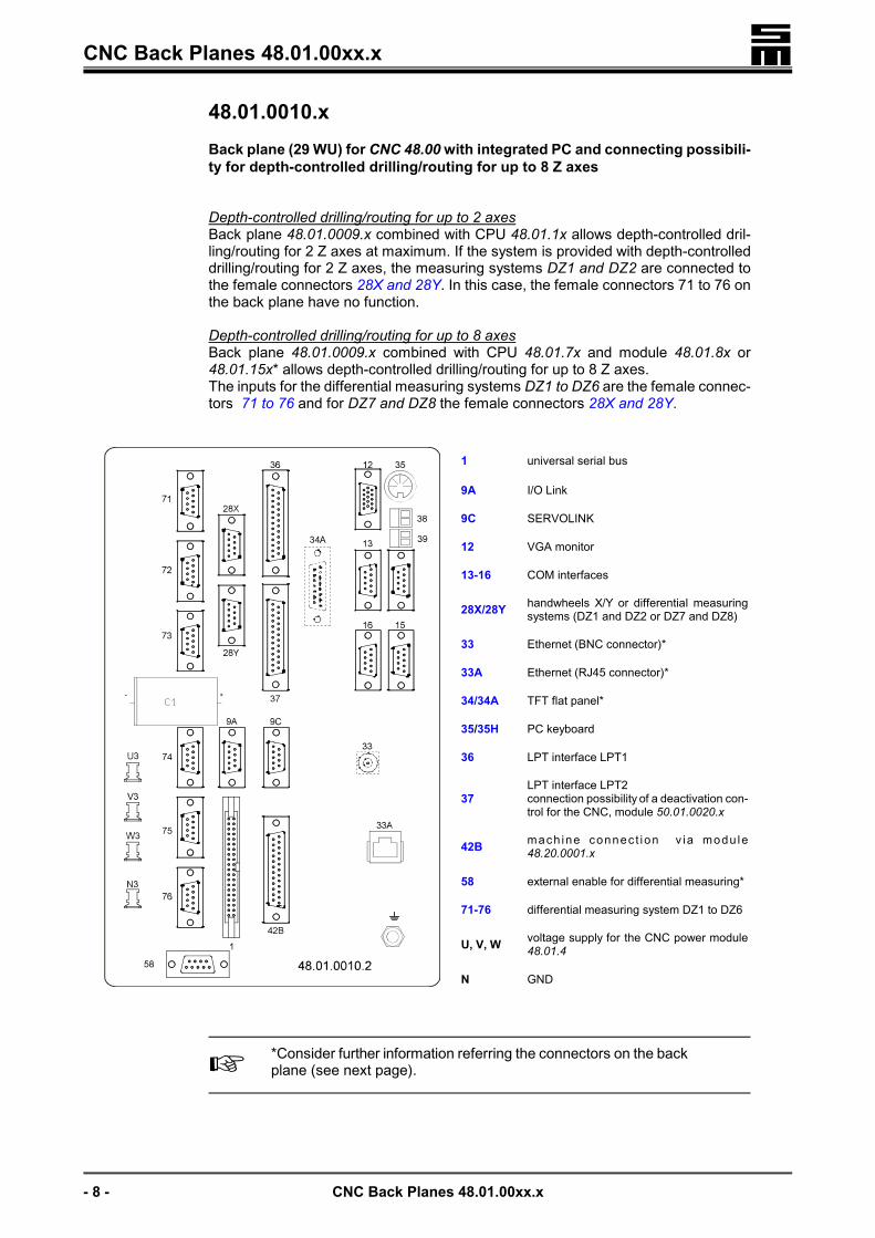
48.01.0010.xBack plane (29 WU) for CNC 48.00 with integrated PC and connecting possibili-ty for depth-controlled drilling/routing for up to 8 Z axes
Depth-controlled drilling/routing for up to 2 axesBack plane 48.01.0009.x combined with CPU 48.01.1x allows depth-controlled dril-ling/routing for 2 Z axes at maximum. If the system is provided with depth-controlleddrilling/routing for 2 Z axes, the measuring systems DZ1 and DZ2 are connected tothe female connectors 28X and 28Y. In this case, the female connectors 71 to 76 onthe back plane have no function.
Depth-controlled drilling/routing for up to 8 axesBack plane 48.01.0009.x combined with CPU 48.01.7x and module 48.01.8x or48.01.15x* allows depth-controlled drilling/routing for up to 8 Z axes.The inputs for the differential measuring systems DZ1 to DZ6 are the female connec-tors 71 to 76 and for DZ7 and DZ8 the female connectors 28X and 28Y.
1 universal serial bus
9A I/O Link
9C SERVOLINK
12 VGA monitor
13-16 COM interfaces
28X/28Y handwheels X/Y or differential measuringsystems (DZ1 and DZ2 or DZ7 and DZ8)
33 Ethernet (BNC connector)*
33A Ethernet (RJ45 connector)*
34/34A TFT flat panel*
35/35H PC keyboard
36 LPT interface LPT1
37LPT interface LPT2connection possibility of a deactivation con-trol for the CNC, module 50.01.0020.x
42B mach ine connec t ion v ia modu le48.20.0001.x
58 external enable for differential measuring*
71-76 differential measuring system DZ1 to DZ6
U, V, W voltage supply for the CNC power module48.01.4
N GND
�*Consider further information referring the connectors on the backplane (see next page).

� CNC Back Planes 48.01.00xx.x
CNC Back Planes 48.01.00xx.x - 9 -
Information on the Connectors on Back Plane 48.01.0010.x
� 28X/28Y (DZ1 and DZ2 or DZ7 and DZ8)Machines which are to be provided with both functions (handwheels and differen-tial measuring systems) must be equipped with module 48.20.0002.x.
� 33/33ASince the driver on the PC card by SIEB & MEYER does not support the BNCconnector, it is not mounted on the CNC back plane from version 48.01.0010.1on. When using this PC card, the Ethernet connection must always be realizedvia connector 33A. However, the slot which is provided on the back plane for aBNC connector can be mounted optionally.
� 34/34AFrom version 48.01.0010.1 on, this slot is provided on the back plane as 15-polefemale submin D connector and is mounted optionally. A TFT flat panel is con-nected via cable 34A. On former versions of the back plane, the slot is conceivedas 34-pole flat cable connector. In this case, cable 34 must be used for connec-ting a TFT flat panel.
� 35/35HThe back plane is equipped with a 5-pole 180� DIN connector. A PC keyboard isconnected via cable 35. PC keyboards with 6-pole DIN connectors (PS/2) areconnected via an appropriate adapter and cable 35H.
� 58Using the function external enable for differential measuring (from PCB version48.01.0010.2 on) will only be possible, if the DZ module 48.01.15x and the CPU48.01.7C or 48.01.7D are provided.
�Consider also special information referring the pin assignment of con-nector 58 when different numbers of Z axes are connected.

�CNC Back Planes 48.01.00xx.x
- 10 - CNC Back Planes 48.01.00xx.x
48.01.0013.xBack plane (22 WU) for CNC 48.00 compact with integrated PC and connectingpossibility for depth-controlled drilling/routing for up to 8 Z axes
Back plane 48.01.0013.x combined with the CPU board of the CNC 48.00 compact(48.01.0012.x) allows depth-controlled drilling/routing for 2 Z axes at maximum. If thesystem is provided with depth-controlled drilling/routing for 2 Z axes, the measuringsystems DZ1 and DZ2 are connected to the female connectors 28X and 28Y.
1 universal serial bus
2/3 voltage supply of the PC via plug-in board50.20.0002.x
9A I/O Link
9C SERVOLINK
12 VGA monitor
COM1 to 4 COM interfaces (cables 13 to 16)
28X/28Y handwheels X/Y or differential measuringsystems*
35B SM keyboard
35H PC keyboard
36 LPT interface LPT1
37LPT interface LPT2connection possibility of a deactivation con-trol for the CNC, module 50.01.0020.x
38 illumination of TFT flat panel*
39 PC reset*
42B machine via module 48.20.0001.x
58 external enable for differential measuring*
USB universal serial interface (connector type A)
U, V, W voltage supply for the CNC power module48.01.4
N GND
�*Consider further information referring the connectors on the backplane (see next page).

� CNC Back Planes 48.01.00xx.x
CNC Back Planes 48.01.00xx.x - 11 -
Information on the Connectors on Back Plane 48.01.0013.x
� 28X/28YMachines which are to be provided with both functions (handwheels and differen-tial measuring systems) must be equipped with module 48.20.0002.x.
� 34AThe connector for a TFT flat panel is provided on the back plane as slot for a 15-pole female submin D connector and is mounted optionally. A TFT flat panel isconnected via cable 34A.
� 38/39The connectors for the illumination of a TFT flat panel (38) and the PC reset (39)are provided as slot for 2-pole PHOENIX contactors on the back plane and aremounted optionally.
� 58Using the function external enable for differential measuring will only be possible,if the DZ module 48.01.15x is provided.
�Consider also special information referring the pin assignment of con-nector 58 when different numbers of Z axes are connected.
�CNC Back Planes 48.01.00xx.x
- 12 - CNC Back Planes 48.01.00xx.x
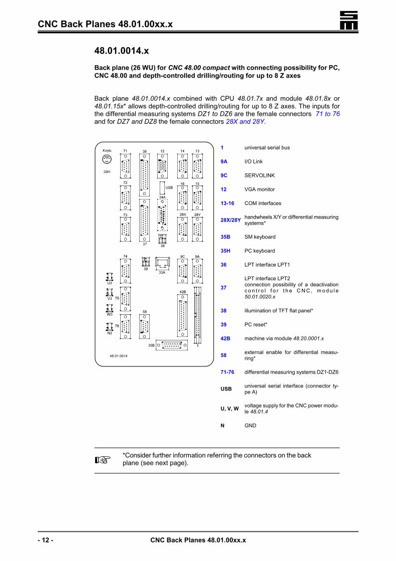
48.01.0014.xBack plane (26 WU) for CNC 48.00 compact with connecting possibility for PC,CNC 48.00 and depth-controlled drilling/routing for up to 8 Z axes
Back plane 48.01.0014.x combined with CPU 48.01.7x and module 48.01.8x or48.01.15x* allows depth-controlled drilling/routing for up to 8 Z axes. The inputs forthe differential measuring systems DZ1 to DZ6 are the female connectors 71 to 76and for DZ7 and DZ8 the female connectors 28X and 28Y.
1 universal serial bus
9A I/O Link
9C SERVOLINK
12 VGA monitor
13-16 COM interfaces
28X/28Y handwheels X/Y or differential measuringsystems*
35B SM keyboard
35H PC keyboard
36 LPT interface LPT1
37LPT interface LPT2connection possibility of a deactivationc o n t r o l f o r t h e C N C , m o d u l e50.01.0020.x
38 illumination of TFT flat panel*
39 PC reset*
42B machine via module 48.20.0001.x
58 external enable for differential measu-ring*
71-76 differential measuring systems DZ1-DZ6
USB universal serial interface (connector ty-pe A)
U, V, W voltage supply for the CNC power modu-le 48.01.4
N GND
�*Consider further information referring the connectors on the backplane (see next page).

� CNC Back Planes 48.01.00xx.x
CNC Back Planes 48.01.00xx.x - 13 -
Information on the Connectors on Back Plane 48.01.0013.x
� 28X/28YMachines which are to be provided with both functions (handwheels and differen-tial measuring systems) must be equipped with module 48.20.0002.x.
� 34AThe connector for a TFT flat panel is provided on the back plane as slot for a 15-pole female submin D connector and is mounted optionally. A TFT flat panel isconnected via cable 34A.
� 38/39The connectors for the illumination of a TFT flat panel (38) and the PC reset (39)are provided as slot for 2-pole PHOENIX contactors on the back plane and aremounted optionally.
� 58Using the function external enable for differential measuring will only be possible,if the DZ module 48.01.15x is provided.
�Consider also special information referring the pin assignment of con-nector 58 when different numbers of Z axes are connected.

�CNC Back Planes 48.01.00xx.x
- 14 - CNC Back Planes 48.01.00xx.x
48.01.0016.xBack plane (20 WU) for CNC 48.00 with connecting possibility for external PCand depth-controlled drilling/routing for up to 2 Z axes
1 universal serial bus
5 voltage supply for external device
9A I/O Link
9C SERVOLINK
12 VGA monitor
17/18 SM Net, connection of external PC
28X/28Y handwheels X/Y or differential measuringsystems*
35B SM keyboard
42B machine via module 48.20.0001.x
58 external enable for differential measuring*
97service switch*If the switch is open, the HDLC connection isinterrupted.
U, V, W voltage supply for the CNC power module48.01.4
N GND
�*Consider further information referring the connectors on the backplane (see next page).

� CNC Back Planes 48.01.00xx.x
CNC Back Planes 48.01.00xx.x - 15 -
Information on the Connectors on Back Plane 48.01.0016.x
� 28X/28YMachines which are to be provided with both functions (handwheels and differen-tial measuring systems) must be equipped with module 48.20.0002.x.
� 58Using the function external enable for differential measuring (from PCB version48.01.0016.1 on) will only be possible, if the DZ module 48.01.15x and the CPU48.01.7C or 48.01.7D are provided.
�Consider also special information referring the pin assignment of con-nector 58 when different numbers of Z axes are connected.

�CNC Back Planes 48.01.00xx.x
- 16 - CNC Back Planes 48.01.00xx.x
Cables and Connectors
Cable 1 - Universal Serial Bus
PinCNC I / O Designation
1 GND2 O +5V3 I RxB4 O TxD5 O TxB6 I RxD
7 O DCTS
8 O DRTS
9 O BRTS
10 O BCTS11 O n.c.12 O n.c.13 O n.c.14 I status signal for jog keys15 O internal S&M interface16 O baud rate17 I TLR magnetic tape rewind18 I DSR (DNC)
19 O TxC keyboard receives date (LEDs inkeys)
20 I RxC keyboard transmits data
21 O TxA tape, reader/puncher, DNC recei-ves data
22 I RxA tape, reader/puncher, DNCtransmits data
23 I ACTS
24 O ARTS
25 O - n.c.select 7
26 O - DNCselect 6
27 O - printerselect 5
28 O - interface (RS 232 C, V24)select 4
29 O - reader/puncher/temperatureselect 3
30 O - Wessel tapeselect 2
31 O - S&M tapeselect 132 O baud rate for keyboard
33 O reset
34 O tape, readerselekt play35 O reader rewind36 I external LF key
37 O +14V38 I external START key
39 O �14V40 GND

� CNC Back Planes 48.01.00xx.x
CNC Back Planes 48.01.00xx.x - 17 -
50.20.0002 - Voltage Supply of the PCVoltage supply of the PC via plug-in PCB 50.20.0002.x
The plug-in PCB 50.20.0002.x is connected to the 10-pole connectors 2 and 3 on thePC back plane. Since the connectors 2 and 3 have different distances, the plug-inPCB will always be connected.
Connector 2 and 3 - DC Voltage Supply of the PCPin I / O Designation1 O
+5V2 O3 O4 O5
GND6789 O
+14V10 O

�CNC Back Planes 48.01.00xx.x
- 18 - CNC Back Planes 48.01.00xx.x
Cable 5 - DC Voltage Supply
Pin E / A Bezeichnung1 A +5 V2 A +5 V3 A frei (Codierstift)456 A +14 V7 A �14 V8 A +24 V9 A �24 V
10GND11
12
Cable 9A - Serial Data for In- and Outputs
Pin I / O Designation Description1 O D out � data from the CNC2 O CLK � clock from the CNC3 O LD � load from the CNC4 I D in � data to the CNC5 0V GND6 O D out + data from the CNC7 O CLK + clock from the CNC8 O LD + load from the CNC9 I D in + data to the CNC
The cable shield is connected to the connector shell.

� CNC Back Planes 48.01.00xx.x
CNC Back Planes 48.01.00xx.x - 19 -
Cable 9C - SERVOLINKCNC/SFU/servo back plane SFU/servo back plane
Pin9-pole female connector
9C/9C SERI / O Designation
Pin9-pole male connector
9C CNCI / O Designation
1 O D out 1 I D in2 O Clock 2 I Clock3 O Load 3 I Load4 I D in 4 O D out5 GND 5 GND6 O D out 6 I D in7 O Clock 7 I Clock8 O Load 8 I Load9 I D in 9 O D out
The cable shield is connected to the connector shell.
Cable 12 - VGA Monitor
Pin I / O Designation1 O red (color signal)2 O green (color signal)3 O blue (color signal)45
GND6789
10 GND111213 O HSYNC14 O VSYNC15
The cable shield is connected to the connector shell.

�CNC Back Planes 48.01.00xx.x
- 20 - CNC Back Planes 48.01.00xx.x
Cable 13 to 16 - COM Interfaces
�The devices connected to these COM interfaces must meet therequirements for RS232 specifications. No devices with PS/2 con-nectors must be connected to these interfaces.
Connector PC/CNC back plane Cable
COM 1 Cable 13COM 2 Cable 14COM 3 Cable 15COM 4 Cable 16
Pin I / O Designation Description1 I DCD data carrier detect2 I RX receive date3 O TX transmit data4 O DTR data transmission ready5 GND ground6 I DSR data set ready7 O RTS request to send8 I CTS clear to send9 I RI ring indicator
The cable shield is connected to the connector shell.

� CNC Back Planes 48.01.00xx.x
CNC Back Planes 48.01.00xx.x - 21 -
Cable 17 / Cable 18 - SM NetPC back plane CNC back plane
Pin9-pole maleconnector
17
I / O Designation
Pin9-pole female con-
nector18
I / O Designation
1 O TX 1 I RX
2 O TX 2 I RX3 34 I RX 4 O TX
5 I RX 5 O TX6 67 78 89 9
Both ends of the cable shield are connected to the connector shell!
A termination connector, in which two wire straps connect pin 1 and 4 as well as pin 2and 5, must be plugged onto connector 17 of the last CNC.
�The internal return line RX and must only be connected in ca-RXbles which have a length of 5m at maximum. For larger distancesan external line must be installed (cable 18)!
PC back plane CNC back plane
Pin9-pole female
connector18
I / O Designation
Pin9-pole male con-
nector18
I / O Designation
1 I / O RX / TX 1 I / O RX / TX
2 I / O / RX TX 2 I / O / RX TX3 34 O TX 4 I RX
5 O TX 5 I RX6 67 78 89 9
Both ends of the cable shield are connected to the connector shell!

�CNC Back Planes 48.01.00xx.x
- 22 - CNC Back Planes 48.01.00xx.x
Cable 28 - Handwheels / Differential Measuring Systems
Pin I / O Designation Description1 I Ua1 pulses 0�2 I Ua1 pulses 0� inverted
3 n.c.4 n.c.5 GND6 I Ua2 pulses 90�7 I Ua2 pulses 90� inverted
8 O +5V +5V measuring system(adjustable via the +5V MSY. setting potentio-meter on the front panel of the power module)
9 n.c.
The cable shield is connected to the connector shell.
Cable 33 - ETHERNET ConnectionPin Designation1 data2 GND / shield
�Since the driver on the PC card by SIEB & MEYER does not sup-port the BNC connector, it is not mounted on the CNC back planefrom version 48.01.0002.1 and 48.01.0010.1 on.
When using this PC card, the Ethernet connection must alwaysbe realized via connector 33A. However, the slot which is provi-ded on the back plane for a BNC connector can be mounted op-tionally.
Cable 33A - ETHERNET ConnectionPin I / O Designation Description1 O TXP
transmit data2 O TXN3 I RXP receive data4 n.c.5 n.c.6 I RXN receive data7 n.c.8 n.c.

� CNC Back Planes 48.01.00xx.x
CNC Back Planes 48.01.00xx.x - 23 -
Cable 34 - TFT Flat PanelPin I / O Designation1 O BXD4 R0 red2 0V GND3 O BXD5 R1 red4 O BXFP VSYNC5 O BXD6 R2 red6 O BXLP HSYNC7 O BXD7 R3 red8
0V GND9
10 O BXSCLKU CK Clock11 O BXD0 G0 green12 0 V GND13 O BXD1 G1 green1415 0V GND1617 O BXD2 G2 green1819 O BXD3 G3 green20
0V GND2122 O VCC (+5V)23 O BXD12 B0 blue24 O VCC (+5V)25 O BXD13 B1 blue2627 0V GND28 O BXFR data enable29 O BXD14 B2 blue30 0V GND31 O BXD15 B3 blue
32-34 n.c.

�CNC Back Planes 48.01.00xx.x
- 24 - CNC Back Planes 48.01.00xx.x
Cable 34A - TFT Flat Panel
Pin I / O Designation1 O data 0+2 GND3 O data 1-4
GND56 O CLK-7 GND8 GND9 O data 0-
10 O data 1+11 O data 2+12 O data 2-13 O CLK+14 O data 3+15 O data 3-
Cable 35 - PC KeyboardPin I / O Designation1 O keyboard clock2 I keyboard data34 0V GND 5 O +5V
Cable 35H - PC-Keyboard (PS/2)
Pin Designation1 DATA2 n.c.3 GND4 +5V5 CLOCK6 n.c.
�If CNC keyboards are used which are equipped with 5-pole 180�DIN connectors, PC keyboards with PS/2 connectors are connec-ted via an appropriate adapter and cable 35H. PC keyboardssupplied by SIEB & MEYER generally include appropriate adap-ters.

� CNC Back Planes 48.01.00xx.x
CNC Back Planes 48.01.00xx.x - 25 -
Cable 35B - CNC Keyboard
�A CNC keyboard by SIEB & MEYER must only be connected fortesting purposes.
Pin I / O Designation1 O +5V2 O +5V3 O TX-C data for LEDs on keys4 n.c.
5 O reset6 I RX-C-keyboard transmits data7 O baud rate8 GND9 O +5V
10 O external START key
11 O external LF key
12 I status signal for jog keys13 O +24V14 GND15 GND, shield
The cable shield is connected to the connector shell.
Cable 36 / Cable 37 - LPT InterfacesPin I / O Designation1 O strobe2 O data 03 O data 14 O data 25 O data 36 O data 47 O data 58 O data 69 O data 7
10 I acknowledge11 I busy12 I printer end13 I select14 I autofeed15 I error16 O init printer17 O select input
18-25 GND
The cable shield is connected to the connector shell.

�CNC Back Planes 48.01.00xx.x
- 26 - CNC Back Planes 48.01.00xx.x
Cable 38 - Illumination for TFT Flat Panel
Pin I / O Designation1 O VCC +12V2 GND 0V
Cable 39 - PC Reset
Pin I / O Designation1 O reset key2 GND 0V
Cable 42B - Machine Connection
Pin I / O Designation1 O light barrier (interrupt)2 O position stop (interrupt)3 I INE D (interrupt)4 I INE B (interrupt)5 n.c.6 O output A7 O output B8 O +5V9 O +14V
10 O -14V11 O +24V12
GND1314 I table stop (interrupt)15 I emergency stop CNC (interrupt)16 I INE C (interrupt)17 I INE A (interrupt)
18 I Start button on the machine
19 O watchdog Servo20 O +5V21 O +5V22 O +24V23 O +24V24
GND25

� CNC Back Planes 48.01.00xx.x
CNC Back Planes 48.01.00xx.x - 27 -
Cable 58 - External Enable for Differential Measuring
Pin I / O Designation Core color1 I DZ-ON Z1 pink2 I DZ-ON Z2 blue3 I DZ-ON Z3 red4 I DZ-ON Z4 white5 I DZ-ON Z5 brown6 I DZ-ON Z6 yellow7 I DZ-ON Z7 green8 I DZ-ON Z8 purple9 n.c.
The cable shield is connected to the connector shell.
�If the function external enable for differential measuring is to beused only for 2 Z axes and the DZ module 48.01.15 is not provi-ded, the pin assignment of connector 58 described above will bechanged and the axes Z1 and Z2 will have to be connected asfollows:
� Z1 > pin 7 ("DZ-ON Z7")
� Z2 > pin 8 ("DZ-ON Z8")

�CNC Back Planes 48.01.00xx.x
- 28 - CNC Back Planes 48.01.00xx.x
Cable 71 to 76 - Differential Measuring Systems
Cable AxisCable 71 Z1Cable 72 Z2Cable 73 Z3Cable 74 Z4Cable 75 Z5Cable 76 Z6
Pinconnector 71 to 76 I / O Designation Description
1 I Ua1 pulses 0�
2 I Ua1 pulses 0� inverted
3 n.c.4 n.c.5 GND ground6 I Ua2 pulses 90�
7 I Ua2 pulses 90� inverted
8 O +5V+5V measuring system(adjustable via the +5V MSY. setting potentiometeron the front panel of the power module)
9 O UaS dirt signal
The cable shield is connected to the connector shell.
Connector 97 - Service SwitchPin Designation1 +24V2 strap