cnc 8055 ·mc· 8055 cnc 8055i ·7· version history here is a list of the features added in each...
TRANSCRIPT

CNC 8055 ·MC·
Operating manual
Ref.1711Soft: V02.2x

This product uses the following source code, subject to the terms of the GPL license. The applications busybox V0.60.2;dosfstools V2.9; linux-ftpd V0.17; ppp V2.4.0; utelnet V0.1.1. The librarygrx V2.4.4. The linux kernel V2.4.4. The linux bootppcboot V1.1.3. If you would like to have a CD copy of this source code sent to you, send 10 Euros to Fagor Automationfor shipping and handling.
All rights reserved. No part of this documentation may be transmitted,transcribed, stored in a backup device or translated into another languagewithout Fagor Automation’s consent. Unauthorized copying or distributing of thissoftware is prohibited.
The information described in this manual may be subject to changes due totechnical modifications. Fagor Automation reserves the right to change thecontents of this manual without prior notice.
All the trade marks appearing in the manual belong to the corresponding owners.The use of these marks by third parties for their own purpose could violate therights of the owners.
It is possible that CNC can execute more functions than those described in itsassociated documentation; however, Fagor Automation does not guarantee thevalidity of those applications. Therefore, except under the express permissionfrom Fagor Automation, any CNC application that is not described in thedocumentation must be considered as "impossible". In any case, FagorAutomation shall not be held responsible for any personal injuries or physicaldamage caused or suffered by the CNC if it is used in any way other than asexplained in the related documentation.
The content of this manual and its validity for the product described here has beenverified. Even so, involuntary errors are possible, hence no absolute match isguaranteed. However, the contents of this document are regularly checked andupdated implementing the necessary corrections in a later edition. We appreciateyour suggestions for improvement.
The examples described in this manual are for learning purposes. Before usingthem in industrial applications, they must be properly adapted making sure thatthe safety regulations are fully met.
DUAL-USE PRODUCTS
Products manufactured by FAGOR AUTOMATION since April 1st 2014 willinclude "-MDU" in their identification if they are included on the list of dual-useproducts according to regulation UE 428/2009 and require an export licensedepending on destination.

Operating manual
CNC 8055CNC 8055i
SOFT: V02.2X
·3·
I N D E X
About the product ......................................................................................................................... 5Version history .............................................................................................................................. 7Safety conditions ........................................................................................................................ 11Returning conditions ................................................................................................................... 15Declaration of conformity and Warranty conditions .................................................................... 17Additional notes .......................................................................................................................... 19Fagor documentation.................................................................................................................. 21
CHAPTER 1 GENERAL CONCEPTS
1.1 Keyboard........................................................................................................................ 231.2 General concepts........................................................................................................... 251.2.1 P999997 text program management.......................................................................... 281.3 Power-up........................................................................................................................ 291.4 Working in M mode with the MC keyboard .................................................................... 301.5 Video off......................................................................................................................... 301.6 Managing the CYCLE START key................................................................................. 30
CHAPTER 2 OPERATING IN JOG MODE
2.1 Introduction .................................................................................................................... 322.1.1 Standard screen of the MC mode .............................................................................. 322.1.2 Special screen of the MC mode ................................................................................. 342.1.3 Standard screen of the MC mode. Configuration of two and half axes...................... 362.1.4 Selecting a program for simulation or execution ........................................................ 382.2 Axis control .................................................................................................................... 392.2.1 Work units .................................................................................................................. 392.2.2 Coordinate preset....................................................................................................... 392.2.3 Managing the axis feedrate (F) .................................................................................. 392.3 Machine reference (home) search ................................................................................. 402.4 Zero offset table ............................................................................................................. 412.5 Jog movement ............................................................................................................... 422.5.1 Moving an axis to a particular position (coordinate)................................................... 422.5.2 Incremental movement............................................................................................... 422.5.3 Continuous jog ........................................................................................................... 432.5.4 Path-jog...................................................................................................................... 442.5.5 Movement with an electronic handwheel ................................................................... 462.5.6 Feed handwheel......................................................................................................... 472.5.7 Path-handwheel ......................................................................................................... 482.6 Tool control .................................................................................................................... 492.6.1 Tool change ............................................................................................................... 512.6.2 Variable tool change point.......................................................................................... 532.7 Tool calibration............................................................................................................... 542.7.1 Define the tool in the tool table (level 1)..................................................................... 552.7.2 Tool calibration without a probe (level 1) ................................................................... 572.7.3 Tool calibration with a probe (level 2) ........................................................................ 592.7.4 Part centering with / without a probe (level 3) ............................................................ 612.7.5 Tabletop probe calibration (level 4)............................................................................ 652.8 Spindle control ............................................................................................................... 672.9 Controlling the external devices..................................................................................... 682.10 ISO management........................................................................................................... 69
CHAPTER 3 WORKING WITH OPERATIONS OR CYCLES
3.1 Operation editing mode.................................................................................................. 733.1.1 Definition of machining conditions.............................................................................. 743.1.2 Safety plane ............................................................................................................... 753.1.3 Cycle level.................................................................................................................. 763.2 Simulating and executing the operation......................................................................... 773.2.1 Background cycle editing ........................................................................................... 783.3 Profile milling operation.................................................................................................. 793.3.1 Definition of data ........................................................................................................ 803.3.2 Profile definition (level 2)............................................................................................ 823.4 Surface milling and slot milling operations..................................................................... 833.4.1 Defining the surface milling data ................................................................................ 843.4.2 Defining the grooving data ......................................................................................... 85

·4·
Operating manual
CNC 8055CNC 8055i
SOFT: V02.2X
3.5 Pocket cycle with a profile ............................................................................................. 873.5.1 Definition of data ........................................................................................................ 893.5.2 Profile definition ......................................................................................................... 903.5.3 Profile definition examples ......................................................................................... 913.6 Rectangular and circular boss cycles ............................................................................ 963.6.1 Definition of data ........................................................................................................ 973.7 Rectangular and circular pocket cycles ......................................................................... 993.7.1 Definition of data ...................................................................................................... 1013.8 Positioning (2 levels).................................................................................................... 1033.8.1 Definition of data ...................................................................................................... 1043.9 Boring operation .......................................................................................................... 1053.9.1 Definition of data ...................................................................................................... 1063.10 Reaming operation ...................................................................................................... 1073.10.1 Definition of data ...................................................................................................... 1083.11 Tapping operation........................................................................................................ 1093.11.1 Definition of data (threading).................................................................................... 1103.11.2 Definition of data (thread milling) ............................................................................. 1123.12 Drilling and center punching operations ...................................................................... 1143.12.1 Definition of data ...................................................................................................... 1163.12.2 Tool withdrawal ........................................................................................................ 1173.13 Multiple positioning ...................................................................................................... 1183.13.1 Multiple positioning in several locations................................................................... 1203.13.2 Multiple positioning in a straight line ........................................................................ 1213.13.3 Multiple positioning in an arc.................................................................................... 1223.13.4 Multiple positioning in a rectangular pattern ............................................................ 1243.13.5 Multiple positioning in a grid pattern ........................................................................ 125
CHAPTER 4 OPERATING IN ISO MODE
4.1 Editing blocks in ISO mode.......................................................................................... 1284.2 Programming assistance ............................................................................................. 1294.2.1 Zero offsets and presets .......................................................................................... 1294.2.2 Work zones .............................................................................................................. 1294.2.3 Insert labels and repetitions from label to label........................................................ 1294.2.4 Mirror image............................................................................................................. 1304.2.5 Scaling factor ........................................................................................................... 1304.2.6 Coordinate rotation .................................................................................................. 1304.2.7 Plane change ........................................................................................................... 131
CHAPTER 5 SAVING PROGRAMS
5.1 List of saved programs ................................................................................................ 1345.2 See the contents of a program .................................................................................... 1355.2.1 Seeing one of the operations in detail...................................................................... 1365.3 Edit a new part-program .............................................................................................. 1375.4 Saving an ISO block or a cycle.................................................................................... 1385.5 Delete a new part program .......................................................................................... 1395.6 Copying a part-program into another one.................................................................... 1405.7 Modify a part-program ................................................................................................. 1415.7.1 Delete an operation.................................................................................................. 1425.7.2 Add or insert a new operation .................................................................................. 1435.7.3 Move an operation to another position..................................................................... 1445.7.4 Modify an existing operation .................................................................................... 1455.8 Managing programs using the explorer ....................................................................... 146
CHAPTER 6 EXECUTION AND SIMULATION
6.1 Simulating or executing an operation or cycle ............................................................. 1486.2 Simulating or executing a part-program....................................................................... 1496.2.1 Simulating or executing a portion of a part-program................................................ 1506.3 Simulating or executing an operation that has been saved ......................................... 1516.4 Execution mode ........................................................................................................... 1526.4.1 Tool inspection......................................................................................................... 1536.5 Graphic representation ................................................................................................ 154

CNC 8055CNC 8055i
·5·
ABOUT THE PRODUCT
BASIC CHARACTERISTICS OF THE DIFFERENT MODELS.
HARDWARE OPTIONS OF THE 8055I CNC
8055i FL EN 8055 FL8055i FL
8055 Power8055i Power
Pendant 8055i FL EN 8055i FL 8055i Power
Enclosure ----- 8055 FL 8055 Power
USB Standard Standard Standard
Block processing time 1 ms 3.5 ms 1 ms
RAM memory 1Mb 1Mb 1 Mb
Software for 7 axes ----- ----- Option
TCP transformation ----- ----- Option
C axis (Lathe) ----- ----- Option
Y axis (Lathe) ----- ----- Option
Look-ahead 100 blocks 100 blocks 200 blocks
Flash Memory 512Mb / 2Gb 512Mb Option Option
Analog Digital Engraving
Ethernet Option Option Option
RS232 serial line. Standard Standard Standard
16 digital inputs and 8 outputs (I1 to I16 and O1 to O8) Standard Standard Standard
Another 40 digital inputs and 24 outputs (I65 to I104 and O33 to O56) Option Option Option
Probe inputs Standard Standard Standard
Spindle (feedback input and analog output) Standard Standard Standard
Electronic handwheels Standard Standard Standard
4 axes (feedback and velocity command) Option Option - - -
Remote CAN modules, for digital I/O expansion (RIO). Option Option - - -
Sercos servo drive system for Fagor servo drive connection. - - - Option - - -
CAN servo drive system for Fagor servo drive connection. - - - Option - - -
Before start-up, verify that the machine that integrates this CNC meets the 89/392/CEE Directive.

·6·
CNC 8055CNC 8055i
Abo
ut th
e pr
oduc
t
SOFTWARE OPTIONS OF THE 8055 AND 8055I CNCS.
Model
GP M MC MCO EN T TC TCO
Number of axes with standard software 4 4 4 4 3 2 2 2
Number of axes with optional software 7 7 7 7 ----- 4 or 7 4 or 7 4 or 7
Electronic threading ----- Stand. Stand. Stand. Stand. Stand. Stand. Stand.
Tool magazine management: ----- Stand. Stand. Stand. ----- Stand. Stand. Stand.
Machining canned cycles ----- Stand. Stand. ----- Stand. Stand. Stand. -----
Multiple machining ----- Stand. Stand. ----- Stand. ----- ----- -----
Solid graphics ----- Stand. Stand. Stand. ----- Stand. Stand. Stand.
Rigid tapping ----- Stand. Stand. Stand. Stand. Stand. Stand. Stand.
Tool life monitoring ----- Opt. Opt. Opt. Stand. Opt. Opt. Opt.
Probing canned cycles ----- Opt. Opt. Opt. Stand. Opt. Opt. Opt.
DNC Stand. Stand. Stand. Stand. Stand. Stand. Stand. Stand.
COCOM version Opt. Opt. Opt. Opt. ----- Opt. Opt. Opt.
Profile editor Stand. Stand. Stand. Stand. ----- Stand. Stand. Stand.
Tool radius compensation Stand. Stand. Stand. Stand. Stand. Stand. Stand. Stand.
Tangential control Opt. Opt. Opt. Opt. ----- Opt. Opt. Opt.
Retracing ----- Opt. Opt. Opt. Stand. Opt. Opt. Opt.
Setup assistance Stand. Stand. Stand. Stand. Stand. Stand. Stand. Stand.
Irregular pockets with islands ----- Stand. Stand. Stand. ----- ----- ----- -----
TCP transformation ----- Opt. Opt. Opt. ----- ----- ----- -----
C axis (on Lathe) ----- ----- ----- ----- ----- Opt. Opt. Opt.
Y axis (on Lathe) ----- ----- ----- ----- ----- Opt. Opt. Opt.
Telediagnosis Opt. Opt. Opt. Opt. Stand. Opt. Opt. Opt.

CNC 8055CNC 8055i
·7·
VERSION HISTORY
Here is a list of the features added in each software version and the manuals that describe them.
The version history uses the following abbreviations:
INST Installation manual
PRG Programming manual
OPT Operating manual
OPT-MC Operating manual for the MC option.
OPT-TC Operating manual for the TC option.
OPT-CO Manual of the CO manual
Software V01.00 October 2010
First version.
Software V01.20 April 2011
Software V01.08 August 2011
Software V01.30 September 2011
List of features Manual
Open communication. INST
Improvements to Look Ahead machining. INST
Blocks with helical interpolation in G51. PRG
G84. Tapping with relief. PRG
List of features Manual
Spindle parameter OPLDECTI (P86). INST
List of features Manual
Gear ratio management on Sercos spindles INST
Improved feedrate limit management (FLIMIT). INST
New type of penetration in lathe type threading cycles. PRG
Improved lathe type thread repair. Partial repair. PRG
MC option: Rigid tapping with relief. OPT-MC
TC option: New type of penetration in threading cycles. OPT-TC
TC option: Improved thread repair. Partial and multi-entry (start) thread repair. OPT-TC
TC option: Zig-zag entry to the groove at the starting point of the groove. OPT-TC

·8·
CNC 8055CNC 8055i
Ver
sion
his
tory
Software V01.31 October 2011
Software V01.40 January 2012
Software V01.60 December 2013
Software V01.65 January 2015
Software V02.00 February 2014
List of features Manual
CNC 8055 FL Engraving model INST / OPT/ PRG
List of features Manual
Execution of M3, M4 and M5 using PLC marks INST / PRG
Values 12 and 43 of variable OPMODE in conversational work mode. INST / PRG
List of features Manual
Auto-adjustment of axis machine parameter DERGAIN. INST
New value for axis machine parameter ACFGAIN (P46). INST
Value 120 of the OPMODE variable. INST / PRG
List of features Manual
Block processing time of 1 ms on the "CNC 8055i FL Engraving" model. INST / OPT/ PRG
List of features Manual
Profile machining in segments. J parameter for G66 and G68 cycles. PRG
Calls to subroutines using G functions. INST / PRG
Anticipated tool management. INST
Managing "PNG" and "JPG" graphic elements. INST
New values for parameters MAXGEAR1..4 (P2..5), SLIMIT (P66) and MAXSPEED (P0). INST
Retracing function of 2000 blocks. INST
Quick block search. OPT
Local subroutines within a program. PRG
Avoid spindle stop with M30 or RESET. Spindle parameter SPDLSTOP (P87). INST
Programming T and M06 with associated with a subroutine in the same line. PRG
New values of the OPMODE variable. INST / PRG
New variables: DISABMOD, GGSN, GGSO, GGSP, GGSQ, CYCCHORDERR. INST / PRG
Possibility to set the parameters of SERCOS nodes in a non-sequential order. INST
WRITE instruction: “$” character followed by “P”. PRG
Cancel additive handwheel offset with G04 K0. General parameter ADIMPG (P176). INST / PRG
Ethernet parameter NFSPROTO (P32). TCP or UDP protocol selection. INST
Face thread repair cycle. OPT TC
Penetration increment (step) in thread repair. INST / OPT TC
API compliant thread. OPT TC
Roughing by segments in inside profiling cycles 1 and 2. INST / OPT TC
Programming the Z increment and the angle on threads. INST / OPT TC
Reversal of the starting and final point of the face thread repair. INST / OPT TC
Manual tool calibration without stopping the spindle during each step. INST / OPT TC

CNC 8055CNC 8055i
·9·
Ver
sion
his
tory
Software V02.03 July 2014
Software V02.10 November 2014
Software V02.21 July 2015
Software V02.22 March 2016
List of features Manual
Set PAGE and SYMBOL instructions support PNG and JPG/JPEG formats. PRG
New values for parameters MAXGEAR1..4 (P2..5), SLIMIT (P66), MAXSPEED (P0) andDFORMAT (P1).
INST
List of features Manual
Incremental zero offset (G158). INST / PRG
Programs identified with letters. OPT
Variables PRGN and EXECLEV. INST
Korean language. INST
Change of default value for general machine parameters: MAINOFFS (P107), MAINTASF (P162)and FEEDTYPE (P170).
INST
New variable EXTORG. INST / PRG
Image handling via DNC. PRG
Save/restore a trace of the oscilloscope. OPT
List of features Manual
PLC library. INST
Zero offsets table in ISO mode. OPT
Compensation of the elastic deformation in the coupling of an axis. INST
Machine axis parameter DYNDEFRQ (P103). INST
Change of maximum value of axis and spindle parameter NPULSES. INST
Operating Terms. OPT
List of features Manual
Axis filters for movements with the handwheel. General machine parameter HDIFFBAC (P129)and machine axis parameter HANFREQ (P104).
INST
Change of maximum value of axis and spindle parameter NPULSES. INST

·10·
CNC 8055CNC 8055i
Ver
sion
his
tory

CNC 8055CNC 8055i
·11·
SAFETY CONDITIONS
Read the following safety measures in order to prevent harming people or damage to this product and thoseproducts connected to it.
The unit can only be repaired by personnel authorized by Fagor Automation.
Fagor Automation shall not be held responsible of any physical or material damage originated from notcomplying with these basic safety rules.
PRECAUTIONS AGAINST PERSONAL HARM
• Interconnection of modules.
Use the connection cables provided with the unit.
• Use proper Mains AC power cables
To avoid risks, use only the Mains AC cables recommended for this unit.
• Avoid electric shocks.
In order to avoid electrical discharges and fire hazards, do not apply electrical voltage outside the rangeselected on the rear panel of the central unit.
• Ground connection.
In order to avoid electrical discharges, connect the ground terminals of all the modules to the mainground terminal. Before connecting the inputs and outputs of this unit, make sure that all the groundingconnections are properly made.
• Before powering the unit up, make sure that it is connected to ground.
In order to avoid electrical discharges, make sure that all the grounding connections are properly made.
• Do not work in humid environments.
In order to avoid electrical discharges, always work under 90% of relative humidity (non-condensing)and 45 ºC (113º F).
• Do not operate this unit in explosive environments.
In order to avoid risks, harm or damages, do not work in explosive environments.

·12·
CNC 8055CNC 8055i
Saf
ety
cond
ition
s
PRECAUTIONS AGAINST PRODUCT DAMAGE
• Work environment.
This unit is ready to be used in industrial environments complying with the directives and regulationseffective in the European Community.
Fagor Automation shall not be held responsible for any damage that could suffer or cause when installedunder other conditions (residential or domestic environments).
• Install this unit in the proper place.
It is recommended, whenever possible, to install the CNC away from coolants, chemical product, blows,etc. that could damage it.
This unit meets the European directives on electromagnetic compatibility. Nevertheless, it isrecommended to keep it away from sources of electromagnetic disturbance, such as:
Powerful loads connected to the same mains as the unit.
Nearby portable transmitters (radio-telephones, Ham radio transmitters).
Nearby radio / TC transmitters.
Nearby arc welding machines.
Nearby high voltage lines.
Etc.
• Enclosures.
It is up to the manufacturer to guarantee that the enclosure where the unit has been installed meetsall the relevant directives of the European Union.
• Avoid disturbances coming from the machine tool.
The machine-tool must have all the interference generating elements (relay coils, contactors, motors,etc.) uncoupled.
DC relay coils. Diode type 1N4000.
AC relay coils. RC connected as close to the coils as possible with approximate values of R=220 1 W y C=0,2 µF / 600 V.
AC motors. RC connected between phases, with values of R=300 / 6 W y C=0,47 µF / 600 V.
• Use the proper power supply.
Use an external regulated 24 Vdc power supply for the inputs and outputs.
• Connecting the power supply to ground.
The zero Volt point of the external power supply must be connected to the main ground point of themachine.
• Analog inputs and outputs connection.
It is recommended to connect them using shielded cables and connecting their shields (mesh) to thecorresponding pin.
• Ambient conditions.
The working temperature must be between +5 ºC and +40 ºC (41ºF and 104º F)
The storage temperature must be between -25 ºC and +70 ºC. (-13 ºF and 158 ºF)
• Monitor enclosure (CNC 8055) or central unit ( CNC 8055i)
Guarantee the required gaps between the monitor or the central unit and each wall of the enclosure.Use a DC fan to improve enclosure ventilation.
• Power switch.
This power switch must be mounted in such a way that it is easily accessed and at a distance between0.7 meters (27.5 inches) and 1.7 meters (5.5ft) off the floor.

CNC 8055CNC 8055i
·13·
Saf
ety
cond
ition
s
PROTECTIONS OF THE UNIT ITSELF (8055)
• "Axes" and "Inputs-Outputs" modules.
All the digital inputs and outputs have galvanic isolation via optocouplers between the CNC circuitryand the outside.
They are protected by an external fast fuse (F) of 3.15 A 250V against overvoltage of the external powersupply (over 33 Vdc) and against reverse connection of the power supply.
• Monitor.
The type of protection fuse depends on the type of monitor. See identification label of the unit itself.
PROTECTIONS OF THE UNIT ITSELF (8055I)
• Central unit.
It has a 4 A 250V external fast fuse (F).
• Inputs-Outputs.
All the digital inputs and outputs have galvanic isolation via optocouplers between the CNC circuitryand the outside.
OUT IN
X7
X1
X8
X9
X2
X10
X3
X11
X4
X12
X5
X13
X6
+24V0V
FUSIBLEFUSES

·14·
CNC 8055CNC 8055i
Saf
ety
cond
ition
s
PRECAUTIONS DURING REPAIRS
SAFETY SYMBOLS
• Symbols that may appear in the manual.
Do not manipulate the inside of the unit. Only personnel authorized by Fagor Automation may accessthe interior of this unit.Do not handle the connectors with the unit connected to AC power. Before manipulating the connectors(inputs/outputs, feedback, etc.) make sure that the unit is not connected to AC power.
Symbol for danger or prohibition.It indicates actions or operations that may cause damage to people or to units.
Warning or caution symbol.It indicates situations that could be caused by certain operations and the actions to take to preventthem.
Mandatory symbol.It indicates actions or operations that MUST be carried out.
Information symbol.It indicates notes, warnings and advises.i

CNC 8055CNC 8055i
·15·
RETURNING CONDITIONS
When sending the central nit or the remote modules, pack them in its original package and packagingmaterial. If you do not have the original packaging material, pack it as follows:
1. Get a cardboard box whose 3 inside dimensions are at least 15 cm (6 inches) larger than those of theunit itself. The cardboard being used to make the box must have a resistance of 170 kg. (375 pounds).
2. Attach a label indicating the owner of the unit, person to contact, type of unit and serial number.
3. In case of failure, also indicate the symptom and a short description of the failure.
4. Protect the unit wrapping it up with a roll of polyethylene or with similar material.
5. When sending the central unit, protect especially the screen.
6. Pad the unit inside the cardboard box with polyurethane foam on all sides.
7. Seal the cardboard box with packaging tape or with industrial staples.
·16·
CNC 8055CNC 8055i
Ret
urni
ng c
ondi
tions

CNC 8055CNC 8055i
·17·
DECLARATION OF CONFORMITY AND WARRANTY CONDITIONS
DECLARATION OF CONFORMITY
The declaration of conformity for the CNC is available in the downloads section of FAGOR’S corporatewebsite at http://www.fagorautomation.com. (Type of file: Declaration of conformity).
WARRANTY TERMS
The warranty conditions for the CNC are available in the downloads section of FAGOR’s corporate websiteat http://www.fagorautomation.com. (Type of file: General sales-warranty conditions).

·18·
CNC 8055CNC 8055i
Dec
lara
tion
of c
onfo
rmity
and
War
rant
y co
nditi
ons

CNC 8055CNC 8055i
·19·
ADDITIONAL NOTES
Mount the CNC away from coolants, chemical products, blows, etc. which could damage it. Before turningthe unit on, verify that the ground connections have been made properly.
To prevent electrical shock at the central unit of the 8055 CNC, use the proper mains AC connector at thepower supply module. Use 3-wire power cables (one for ground connection).
To prevent electrical shock at the monitor of the 8055 CNC, use the proper mains AC connector (A) with3-wire power cables (one of them for ground connection).
Before turning on the monitor of the 8055 CNC and verifying that the external AC line (B) fuse of each unitis the right one. See identification label of the unit itself.
In case of a malfunction or failure, disconnect it and call the technical service. Do not get into the insideof the unit.
FAGOR
I/O
X1
X2
X3
AXES
X1 X2
X3 X4
X5 X6
X7 X8
X9X10
CPU
X1 X2
CMPCTFLASH
ETH
COM1
X3
CDEF0
BA98 1
7 26 354
IN
OUT
NODE
USB
(A)
(B)
X1
W1

·20·
CNC 8055CNC 8055i
Add
ition
al n
otes
CNC 8055CNC 8055i
·21·
FAGOR DOCUMENTATION
OEM manual
It is directed to the machine builder or person in charge of installing and starting-up the CNC.
USER-M manual
Directed to the end user.
It describes how to operate and program in M mode.
USER-T manual
Directed to the end user.
It describes how to operate and program in T mode.
MC Manual
Directed to the end user.
It describes how to operate and program in MC mode.
It contains a self-teaching manual.
TC Manual
Directed to the end user.
It describes how to operate and program in TC mode.
It contains a self-teaching manual.
MCO/TCO model
Directed to the end user.
It describes how to operate and program in MCO and TCO mode.
Examples-M manual
Directed to the end user.
It contains programming examples for the M mode.
Examples-T manual
Directed to the end user.
It contains programming examples for the T mode.
WINDNC Manual
It is directed to people using the optional DNC communications software.
It is supplied in a floppy disk with the application.
WINDRAW55 Manual
Directed to people who use the WINDRAW55 to create screens.
It is supplied in a floppy disk with the application.

·22·
CNC 8055CNC 8055i
Fag
or d
ocum
enta
tion
CNC 8055CNC 8055i
·MC· OPTIONSOFT: V02.2X
1
·23·
GENERAL CONCEPTS
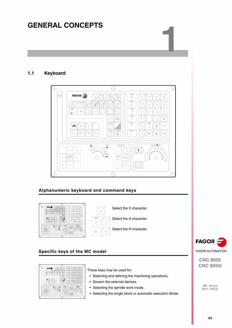
1.1 Keyboard
Alphanumeric keyboard and command keys
Specific keys of the MC model
Select the X character.
Select the A character.
Select the R character.
These keys may be used for:
• Selecting and defining the machining operations.
• Govern the external devices.
• Selecting the spindle work mode.
• Selecting the single block or automatic execution Mode.

·24·
Operating manual
CNC 8055CNC 8055i
1.
GE
NE
RA
L C
ON
CE
PT
S
·MC· OPTIONSOFT: V02.2X
Key
boar
d
JOG keys
These keys may be used for:
• Moving the axes of the machine.
• Governing the spindle.
• Modifying the feedrate of the axes and the spindle speed.
• Starting and stopping the execution.

Operating manual
CNC 8055CNC 8055i
GE
NE
RA
L C
ON
CE
PT
S
1.
·MC· OPTIONSOFT: V02.2X
·25·
Gen
eral
con
cept
s
1.2 General concepts
It offers all the features of the M model plus those specific of the MC mode. For example, the CNCsetup must be done in M mode.
In MC work mode, programs P900000 through P999999 are reserved for the CNC itself; in otherwords, the user cannot use them as part-programs.
On the other hand, in order to work in MC mode, the CNC must have programs P999997 andP999998 stored in its memory. Both programs are related to the software version and, consequently,are not supplied by Fagor Automation. Whenever the CNC detects a new software version, it updatesthese programs automatically and, for safety, it makes a copy of the old ones in the KeyCF.
Likewise, subroutines 0000 through 8999 are free to use and subroutines 9000 through 9999 arereserved for the CNC.
Subroutines reserved for the CNC
Some of the subroutines reserved for the CNC have the following meaning:
Both subroutines must be defined by the machine manufacturer, even when no operation is to becarried out at the beginning and at the end of the part-program. If they are not defined, the CNCwill issue an error message when trying to execute a part-program.
OEM (manufacturer's) parameters
OEM parameters and subroutines with OEM parameters can only be used in OEM programs; thosedefined with the [O] attribute. Modifying one of these parameters in the tables requires an OEMpassword.
When using OEM parameters in the configuration programs, this program must have the [O]attribute; otherwise, the CNC will issue an error when editing the user cycles that refer to OEMparameters in write mode.
Programs P999997 and P999998 are associated with the software version. Fagor Automation shallnot be held responsible of the CNC's performance if programs P999997 and P999998 have beendeleted from memory or do not match the software version.
9998 Subroutine that the CNC will execute at the beginning of each part-program.
9999 Subroutine that the CNC will execute at the end of each part-program.
Every time a new part-program is edited, the CNC inserts a call to the relevantsubroutine at the beginning and at the end of the program.
Example of how to define subroutine 9998.(SUB 9998) ; Definition of subroutine 9998.··· ; Program blocks defined by the OEM.(RET) ; End of subroutine.

·26·
Operating manual
CNC 8055CNC 8055i
1.
GE
NE
RA
L C
ON
CE
PT
S
·MC· OPTIONSOFT: V02.2X
Gen
eral
con
cept
s
Programs reserved for the CNC
Some of the programs reserved for the CNC have the following meaning:
P999998
It is a program of subroutines that the CNC uses to interpret the programs edited in MC format andexecute them later on.
P999997
It is a text program that contains:
• The sentences and texts that will be displayed on the various screens of the MC mode.
• The help texts for the icons, in the work cycles, that are shown on the lower left side of the screen.
• The messages (MSG) and errors (ERR) that may come up at the MC model.
All the texts, messages and errors that may be translated into the desired language.
Considerations about the texts.
The format of a line is as follows:
;Text number - explanatory comment (not displayed) - $Text to be displayed
All the program lines must begin with the ";" character and the text to be displayed must be precededby the "$" symbol. If a line begins with ";;", the CNC assumes that the whole line is a programcomment.
Examples:
;44 $M/MIN Is message 44 and displays the text "M/MIN";;General text The CNC treats it as a comment;;44 Feedrate $M/MIN The CNC treats it as a comment;44 Feedrate $M/MIN Is message 44 whose hidden explanatory comment is "Feedrate" and displays the text "M/MIN"
Considerations about the messages.
The format must be respected. Only the text after SAVEMSG may be translated:
Example:
Original message: N2002(MSG"SAVEMSG: DRILLING 1")Translated message: N2002(MSG"SAVEMSG: 1 ZULAKETA ZIKLOA")
This program must not be modified. If this program is modified or deleted, Fagor Automation will notbe held responsible of the CNC's performance.If the manufacturer needs to create his own subroutines (for home search, tool change, etc.), as wellas subroutines 9998 and 9999, they must be included in another program, for example P899999.
When modifying program 999997, it is recommended to make a backup copy of it because the CNCreplaces that program when selecting another language or updating the software version.i

Operating manual
CNC 8055CNC 8055i
GE
NE
RA
L C
ON
CE
PT
S
1.
·MC· OPTIONSOFT: V02.2X
·27·
Gen
eral
con
cept
s
Considerations about the errors.
The format must be respected. Only the text between quote marks ("text") may be translated.
Example:
Original text: N1021(ERROR"TALADRADO 1: F=0")Translated text: N1001(ERROR"1 ZULAKETA ZIKLOA: F=0")
P998000 ··· P998999
They are the profiles for the pocket-with-profile cycle that are defined by the user with the profileeditor. In the MC mode, the user defines them with 3 digits (from 0 to 999) and the CNC saves theminternally as P998xxx.
P997000 ··· P997999
They are the profiles for the profile milling operation that are defined by the user with the profile editor.In the MC mode, the user defines them with 3 digits (from 0 to 999) and the CNC saves them internallyas P997xxx.

·28·
Operating manual
CNC 8055CNC 8055i
1.
GE
NE
RA
L C
ON
CE
PT
S
·MC· OPTIONSOFT: V02.2X
Gen
eral
con
cept
s
1.2.1 P999997 text program management
On power up, the CNC copies the texts of program P999997 into the system memory.
• It checks if program P999997 is in user memory, if not, it looks in the KeyCF and if it is not thereeither, it assumes the default ones and copies them into program P999997 of the user memory.
• When selecting mainland Chinese, it ignores program P999997 and it always assumes thedefault ones.
If when switching from M mode to MC or MCO mode, it cannot find program P999997 because ithas been deleted, it is initialized like on power-up.
When modifying the texts of program P999997, turn the CNC off and back on so it assumes thenew texts.
The CNC carries out the following operations when changing the language, the software versionand when adding MC, MCO conversational modes (new software features):
• It copies, for safety, the texts that were being used into KeyCF as program P999993.
• It deletes the program P999997 that may be in the KeyCF.
• It assumes the new texts that are provided by default and copies them into program P999997of the user memory.
To change the texts, after modifying program P999997, turn the CNC off and back on so it assumesthe new texts.

Operating manual
CNC 8055CNC 8055i
GE
NE
RA
L C
ON
CE
PT
S
1.
·MC· OPTIONSOFT: V02.2X
·29·
Pow
er-u
p
1.3 Power-up
The standard screen of the MC mode is the following:
On power-up and after the keystroke sequence [SHIFT] [RESET], the CNC shows"page 0" defined by the manufacturer; if there is no "page 0", it shows the standardscreen of the work mode. Press any key to access the work mode.
There are 2 work modes: MC work mode and M work mode. Press the keysequence [SHIFT] [ESC] to go from one work mode to the other.
The CNC setup must be done in M mode.Likewise, some errors must be eliminated in M mode.

·30·
Operating manual
CNC 8055CNC 8055i
1.
GE
NE
RA
L C
ON
CE
PT
S
·MC· OPTIONSOFT: V02.2X
Wor
king
in M
mod
e w
ith th
e M
C k
eybo
ard
1.4 Working in M mode with the MC keyboard
The MC keyboard is designed to also be able to work in M mode. In M mode, use the alphanumerickeyboard and the keys that replace the softkeys F1 through F7.
1.5 Video off
Also, any message (PLC, program, etc.) restores the CNC image.
1.6 Managing the CYCLE START key
In order to avoid undesired executions when pressing key sequences that are not supported in MCmode, the CNC changes the "Start" icon at the top of the window from green to gray and shows amessage indicating that it is an invalid action.
For example, if "M3 Start" is pressed (sequence not supported in MC mode) while a part-programis selected, the CNC issues a warning and prevents the selected part-program from running whendetecting the "Start" key.
There are 2 work modes: MC work mode and M work mode. Press the keysequence [SHIFT] [ESC] to go from one work mode to the other.
Alphanumeric keyboard:
The keys that replace the softkeys F1 through F7are:
The keystroke sequence [SHIFT] [CLEAR] clears the CRT screen (it goes blank).Press any key to restore the image.

CNC 8055CNC 8055i
·MC· OPTIONSOFT: V02.2X
2
·31·
OPERATING IN JOG MODE
The standard screen of the MC mode is the following:
When pressing the two-color key, the CNC shows the special screen of the MC mode.

·32·
Operating manual
CNC 8055CNC 8055i
2.
OP
ER
AT
ING
IN J
OG
MO
DE
·MC· OPTIONSOFT: V02.2X
Intr
oduc
tion
2.1 Introduction
2.1.1 Standard screen of the MC mode
The standard screen of the MC mode offers the following data:
1. Clock.
2. This window may show the following data:
SBK when "single block" execution mode is selected.
DNC when the DNC mode is active.
P..... Number of the program currently selected.
Message "In position" - "Execution" - "Interrupted" - "RESET".
PLC messages.
3. This window shows the CNC messages.
4. This window may show the following data:
X, Y, Z coordinates of the axes.
In small characters, the axis coordinates referred to machine reference zero. These values areuseful when letting the user define a tool change point (see zone 6) The CNC shows this datawhen text 33 of program 999997 has not been defined.
The coordinates of the auxiliary axes that are defined.
The real spindle rpm.
5. The information shown in this window depends on the position of the left switch.
In all cases, it shows the axis feedrate "F" currently selected and the % of F being applied.
When feed-hold is active, the color of the feedrate value changes.

Operating manual
CNC 8055CNC 8055i
OP
ER
AT
ING
IN J
OG
MO
DE
2.
·MC· OPTIONSOFT: V02.2X
·33·
Intr
oduc
tion
Here are all the possible cases.
6. This window shows, in large characters, the selected tool number "T" and, in small characters,the "D" offset associated with the tool. If the tool number and the offset number are the same,the CNC will not show the "D" value.
This window also shows the coordinates of the tool change point referred to machine referencezero. The CNC does not show this window when text 47 of program 999997 has not been defined.
7. This window shows everything related to the spindle:
The real spindle speed "S".
The spindle status. It is represented with an icon and may be turning clockwise, counterclockwiseor stopped.
The % of spindle speed being applied.
The active spindle speed gear (range). The CNC does not show this data when text 28 of program999997 has not been defined.
8. When accessing a work cycle, this window shows the help text associated with the selected icon.
That help text must be defined in program P999997 and edited in the desired language. Seechapter "1 General concepts".
9. Reserved.
Displaying the active PLC messages
At the screen, press [+] of the alphanumeric keyboard, the CNC shows a window with all the activePLC messages. Besides, this window is also displayed whenever there is a program in execution.
The [] [] [PG UP] [PG DW] keys are used to move around the messages. The [ESC] key is usedto close the window.
The window is only displayed when there are more than one active message.
Direct access to the oscilloscope
The oscilloscope may be accessed from the standard screen by pressing "7" and then "1" as longas no data is being written into any field.
·34·
Operating manual
CNC 8055CNC 8055i
2.
OP
ER
AT
ING
IN J
OG
MO
DE
·MC· OPTIONSOFT: V02.2X
Intr
oduc
tion
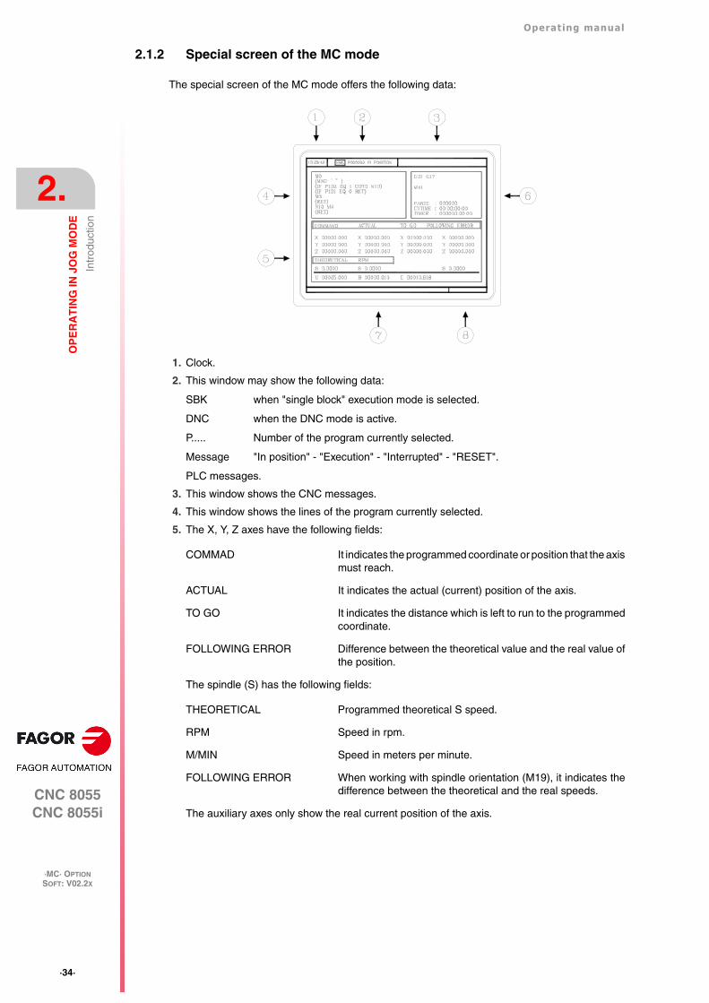
2.1.2 Special screen of the MC mode
The special screen of the MC mode offers the following data:
1. Clock.
2. This window may show the following data:
SBK when "single block" execution mode is selected.
DNC when the DNC mode is active.
P..... Number of the program currently selected.
Message "In position" - "Execution" - "Interrupted" - "RESET".
PLC messages.
3. This window shows the CNC messages.
4. This window shows the lines of the program currently selected.
5. The X, Y, Z axes have the following fields:
The spindle (S) has the following fields:
The auxiliary axes only show the real current position of the axis.
COMMAD It indicates the programmed coordinate or position that the axismust reach.
ACTUAL It indicates the actual (current) position of the axis.
TO GO It indicates the distance which is left to run to the programmedcoordinate.
FOLLOWING ERROR Difference between the theoretical value and the real value ofthe position.
THEORETICAL Programmed theoretical S speed.
RPM Speed in rpm.
M/MIN Speed in meters per minute.
FOLLOWING ERROR When working with spindle orientation (M19), it indicates thedifference between the theoretical and the real speeds.
Operating manual
CNC 8055CNC 8055i
OP
ER
AT
ING
IN J
OG
MO
DE
2.
·MC· OPTIONSOFT: V02.2X
·35·
Intr
oduc
tion
6. This window shows the status of the "G" functions and the auxiliary "M" functions that are active.Likewise, it shows the value of the variables.
7. Reserved.
8. Reserved.
Displaying the active PLC messages
At the screen, press [+] of the alphanumeric keyboard, the CNC shows a window with all the activePLC messages. Besides, this window is also displayed whenever there is a program in execution.
The [] [] [PG UP] [PG DW] keys are used to move around the messages. The [ESC] key is usedto close the window.
The window is only displayed when there are more than one active message.
Direct access to the oscilloscope
The oscilloscope may be accessed from the auxiliary screen by pressing "7" and then "1" as longas no data is being written into any field.
PARTC It indicates the number of consecutive parts executed with the same part-program.
Every time a new program is selected, this variable is reset to "0".
CYTIME It indicates the time elapsed while executing the part. It is given in "hours: minutes:seconds: hundredths of a second" format.
Every time a part-program execution starts, even when repetitive, this variable isreset to "0".
TIMER It indicates the count of the timer enabled by PLC. It is given in "hours: minutes:seconds" format.

·36·
Operating manual
CNC 8055CNC 8055i
2.
OP
ER
AT
ING
IN J
OG
MO
DE
·MC· OPTIONSOFT: V02.2X
Intr
oduc
tion
2.1.3 Standard screen of the MC mode. Configuration of two and half axes
A two-and-a-half-axis configuration is a milling machine where the X and Y axes are motorized andthe Z axis is set as a DRO axis (display only). In this configuration, the Z axis is moved manually.
The CNC interface for this type of configuration looks like this.
Editing and execution
The cycles are edited, stored and simulated just like a 3-axis configuration.
The most significant different lays in the execution because the operator must move the Z axis byhand. The standard screen shows the operations to be carried out by the operator. In each case,it shows the status of the Z axis and the various actions to be executed by the operator.
• Move Z up (it shows an icon next to the final Z coordinate).
The operator must move the axis up manually. When the Z axis is in position, the message willchange.
• Move Z down (it shows an icon next to the final Z coordinate).
The operator must move the axis down manually. When the Z axis is in position, the messagewill change.
• Press CYCLE START.
The operator must press [CYCLE START] to begin the X-Y movement in automatic.
• Moving in X-Y.
The machine is moving in X-Y. When a Z axis move is required, the machine will stop and it willrequest the operator's intervention.
• Tool inspection.
It went into tool inspection.
Operating manual
CNC 8055CNC 8055i
OP
ER
AT
ING
IN J
OG
MO
DE
2.
·MC· OPTIONSOFT: V02.2X
·37·
Intr
oduc
tion
Canned cycles
Not all the cycles can be applied to a two-and-a-half-axis configuration. The following cycles arepermitted. In some of these cycles, some data has been eliminated to adapt them to the two-and-a-half-axis configuration. This data referred to operations of the Z axis.
• Positioning 1 and 2.
• Profile milling and profile 1 milling.
• Surface milling.
• Slot milling.
• 2D profile pocket.
• Rectangular and circular boss.
• Simple, rectangular and circular pocket 1 and 2.
• Center punching.
• Drilling 1.
• Reaming.
• Boring 1 and 2.
• Multiple positioning, point to point, linear, in arc 1 and 2, in grid and rectangular patterns.

·38·
Operating manual
CNC 8055CNC 8055i
2.
OP
ER
AT
ING
IN J
OG
MO
DE
·MC· OPTIONSOFT: V02.2X
Intr
oduc
tion
2.1.4 Selecting a program for simulation or execution
When selecting a part-program or operation saved as part of a part-program for simulation orexecution, the CNC selects that part-program and shows it highlighted next to the green "start"symbol in the top center window.
When the top center window shows the part-program selected next to the green "start" symbol, theCNC acts as follows:
• If [START] is pressed, the CNC executes the part-program that is selected.
• If [CLEAR] is pressed, the CNC de-selects the part-program and removes it from the top centerwindow.

Operating manual
CNC 8055CNC 8055i
OP
ER
AT
ING
IN J
OG
MO
DE
2.
·MC· OPTIONSOFT: V02.2X
·39·
Axi
s co
ntro
l
2.2 Axis control
2.2.1 Work units
When accessing the MC mode, the CNC assumes the work units "mm or inches", "mm/min. ormm/rev", etc. selected by machine parameter.
To modify those values, access the M mode and change the corresponding machine parameter.
2.2.2 Coordinate preset
The coordinates must be preset on one axis at a time proceeding as follows:
1. Press the key of the desired axis, [X], [Y] or [Z].
The CNC will highlight the coordinate of that axis indicating that it is selected.
2. Key in the value to preset the axis.
To quit the preset mode, press [ESC].
3. Press [ENTER] for the CNC to assume that value as the new value for the point.
The CNC requests confirmation of the command. Press the [ENTER] to confirm it or [ESC] toquit the preset mode.
2.2.3 Managing the axis feedrate (F)
To set a particular axis feedrate value, proceed as follows:
1. Press the [F] key.
The CNC will highlight the current value that it is selected.
2. Key in the desired new feedrate value.
To quit the preset selection mode, press [ESC].
3. Press [START] for the CNC to assume that value as the new value for axis feedrate.

·40·
Operating manual
CNC 8055CNC 8055i
2.
OP
ER
AT
ING
IN J
OG
MO
DE
·MC· OPTIONSOFT: V02.2X
Mac
hine
ref
eren
ce (
hom
e) s
earc
h
2.3 Machine reference (home) search
Home search may be done in 2 ways:
• Homing all the axes.
• Homing a single axis.
Homing all the axes
To home all the axes, press [ZERO].
The CNC requests confirmation of the command (text 48 of program 999997). Press [START], theCNC will execute the home search subroutine defined by the OEM in general machine parametersP34 (REFPSUB).
Homing a single axis
To home a single axis, press the key of the desired axis and the key for home search.
In either case, the CNC requests confirmation of the command (text 48 of program 999997).
After searching home this way, the CNC will maintain the part zero or zero offset active at the time.A home search subroutine (general machine parameter P34 other than 0) must be defined when usingthis method. Otherwise, the CNC will display the corresponding error.
i
It homes the X axis.
It homes the Y axis.
It homes the Z axis.
After searching home this way, the CNC will not maintain the part zero or zero offset active at the timeand assumes the machine reference zero as the new part zero.i

Operating manual
CNC 8055CNC 8055i
OP
ER
AT
ING
IN J
OG
MO
DE
2.
·MC· OPTIONSOFT: V02.2X
·41·
Zer
o of
fset
tabl
e
2.4 Zero offset table
It is possible to manage the zero offset table from the conversational mode (G54.... G59, G159N7... G159N20). This table contains the same values as that of the conversational mode.
Press the [ZERO] key to access the zero offset table as well as to get out of it. The zero offset tablemay be accessed in the following ways.
• From the standard screen, as long as no axis is selected. The CNC will request confirmationof the command.
• From ISO mode, when the "zero offsets and presets" cycle is selected.
The zero offset table looks like this. It shows all the offsets, PLC offset included, and their value ineach axis.
When scrolling the focus through the table, the elements appear in different colors as follows.
How to edit the table data
The following operations are possible in the zero offset table. Press [ENTER] to validate anychanges.
• Editing a zero offset.
It is edited one axis at a time. Select a data with the focus and edit its value. If the magnifyingglass is placed on top of an offset (G54 ... G59, G159N7 ... G159N20), editing start on the firstaxis of that offset.
• Load the active zero offset into the table.
Position the magnifying glass over the offset you wish to define (G54 ... G59, G159N7 ...G159N20) and click on the [RECALL] key. The active preset is saved in the selected zero offset.
If instead of placing the focus on a zero offset, it is placed on one of the axes, only that axis willbe affected.
• Deleting a zero offset.
Position the magnifying glass over the offset that you wish to erase (G54 ... G59, G159N7 ...G159N20) and click on the [CLEAR] key. All the axes of that zero offset are reset to zero.
If instead of placing the focus on a zero offset, it is placed on one of the axes, only that axis willbe affected.
Color Meaning
Green background.Text in white.
The real value of the table and the value shown on the screen are the same.
Red background.White text.
The real value of the table and the value shown on the screen are NOT the same.The value on the table has been changed, but it has not been validated. Press[ENTER] to validate the change.
Blue background. The zero offset is active.Two origins may be active simultaneously, one absolute (G54 ... G57, G159N7... G159N20) and another incremental (G58-G59).

·42·
Operating manual
CNC 8055CNC 8055i
2.
OP
ER
AT
ING
IN J
OG
MO
DE
·MC· OPTIONSOFT: V02.2X
Jog
mov
emen
t
2.5 Jog movement
When making a move in manual, both in jog and with handwheels, the moving axis appears inreverse video.
• With gantry axes, only the master axis is highlighted.
• With a path handwheel, no axis is highlighted; but it is in path-jog.
2.5.1 Moving an axis to a particular position (coordinate)
The movements of axes to a particular coordinate are made one at a time as follows.
2.5.2 Incremental movement
Turn the JOG switch to one of the JOG positions.
The incremental movement must be made one axis at a time. To do that, press the JOG keys forthe direction of the axis to be jogged.
Every time a key is pressed, the corresponding axis moves the amount set by the switch. Thismovement is made at the selected feedrate (F).
[target coordinate]
[target coordinate]
[target coordinate]
Switch position Distance
1 0.001 mm or 0.0001 inches
10 0.010 mm or 0.0010 inches
100 0.100 mm or 0.0100 inches
1000 1.000 mm or 0.1000 inches
10000 10.000 mm or 1.0000 inches

Operating manual
CNC 8055CNC 8055i
OP
ER
AT
ING
IN J
OG
MO
DE
2.
·MC· OPTIONSOFT: V02.2X
·43·
Jog
mov
emen
t
2.5.3 Continuous jog
Place the movement selector in the continuous-jog position and select at the feedrate override switch(FEED) the percentage (0% to 120%) of the feedrate to be applied.
The continuous jog must be made one axis at a time. To do that, press the JOG keys for the directionof the axis to be jogged.
The axis moves at a feedrate equal to the selected percentage (0% to 120%) of feedrate "F".
Depending on the status of the general logic input "LATCHMAN", the movement will be carried outas follows:
• If the PLC sets this mark low, the axis will be jogged while pressing the corresponding Jog key.
• If the PLC sets this mark high, the axes will start moving from the moment the JOG key is presseduntil the same is pressed again, or another JOG key is pressed. In this case, the movement willbe transferred to that indicated by the new key.
The following cases are possible when working with "F" in mm/rev:
• The spindle is running.
• The spindle is stopped, but a spindle speed S has been selected.
• The spindle is stopped and no spindle speed S has been selected.
The spindle is running.
The spindle is stopped, but a spindle speed S has been selected.
The spindle is stopped and no spindle speed S has been selected.
If while jogging an axis, the rapid key is pressed, the axis will move at the maximumfeedrate possible, set by axis machine parameter "G00FEED". This feedrate will beapplied while that key is kept pressed and the previous feedrate will be restored whenthat key is released.
The CNC moves the axes at the programmed F.
The CNC calculates the feedrate F in mm/min for the theoretical S and movesthe axis.
For example if "F 2.000" and "S 500":
F (mm/min) = F (mm/rev) x S (mm/rev) = 2 x 500 = 1000 mm/min.
The axis moves at a feedrate of 1000 mm/min.
If F = 0, the CNC moves the axes in rapid.
If F is other than 0, the axes can only be moved by pressing the rapid key andan axis key. The CNC moves the axis in rapid.
·44·
Operating manual
CNC 8055CNC 8055i
2.
OP
ER
AT
ING
IN J
OG
MO
DE
·MC· OPTIONSOFT: V02.2X
Jog
mov
emen
t
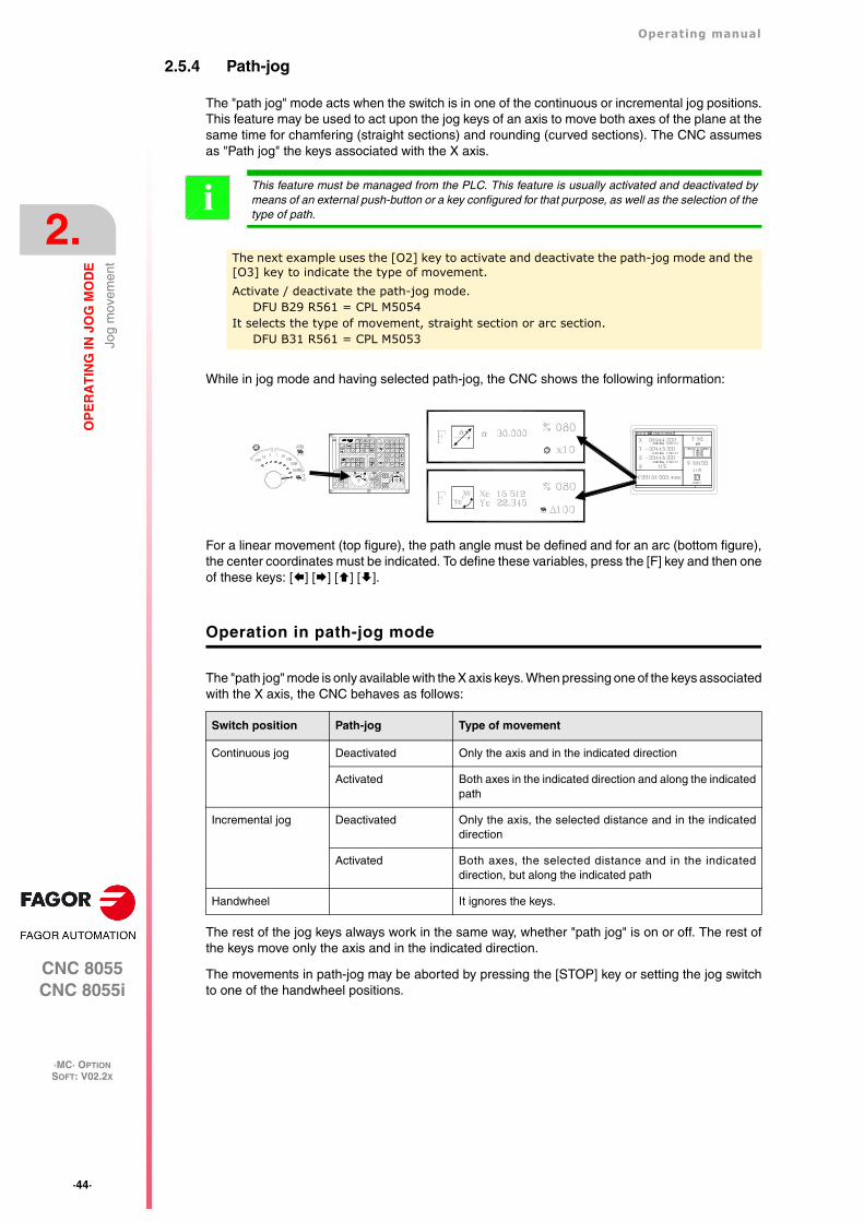
2.5.4 Path-jog
The "path jog" mode acts when the switch is in one of the continuous or incremental jog positions.This feature may be used to act upon the jog keys of an axis to move both axes of the plane at thesame time for chamfering (straight sections) and rounding (curved sections). The CNC assumesas "Path jog" the keys associated with the X axis.
While in jog mode and having selected path-jog, the CNC shows the following information:
For a linear movement (top figure), the path angle must be defined and for an arc (bottom figure),the center coordinates must be indicated. To define these variables, press the [F] key and then oneof these keys: [] [] [] [].
Operation in path-jog mode
The "path jog" mode is only available with the X axis keys. When pressing one of the keys associatedwith the X axis, the CNC behaves as follows:
The rest of the jog keys always work in the same way, whether "path jog" is on or off. The rest ofthe keys move only the axis and in the indicated direction.
The movements in path-jog may be aborted by pressing the [STOP] key or setting the jog switchto one of the handwheel positions.
This feature must be managed from the PLC. This feature is usually activated and deactivated bymeans of an external push-button or a key configured for that purpose, as well as the selection of thetype of path.
iThe next example uses the [O2] key to activate and deactivate the path-jog mode and the [O3] key to indicate the type of movement.Activate / deactivate the path-jog mode.
DFU B29 R561 = CPL M5054It selects the type of movement, straight section or arc section.
DFU B31 R561 = CPL M5053
Switch position Path-jog Type of movement
Continuous jog Deactivated Only the axis and in the indicated direction
Activated Both axes in the indicated direction and along the indicatedpath
Incremental jog Deactivated Only the axis, the selected distance and in the indicateddirection
Activated Both axes, the selected distance and in the indicateddirection, but along the indicated path
Handwheel It ignores the keys.

Operating manual
CNC 8055CNC 8055i
OP
ER
AT
ING
IN J
OG
MO
DE
2.
·MC· OPTIONSOFT: V02.2X
·45·
Jog
mov
emen
t
Considerations about the jog movements
This mode assumes as axis feedrate the one selected in jog mode and it will also be affected bythe feedrate override switch. If F0 is selected, it assumes the one indicated by machine parameter"JOGFEED (P43)". This mode ignores the rapid jog key.
Path-jog movements respect the travel limits and the work zones.

·46·
Operating manual
CNC 8055CNC 8055i
2.
OP
ER
AT
ING
IN J
OG
MO
DE
·MC· OPTIONSOFT: V02.2X
Jog
mov
emen
t
2.5.5 Movement with an electronic handwheel
This option may be used to govern the movements of the machine using an electronic handwheel.To do that, turn the left switch to any of the handwheel positions.
The positions available are 1, 10 and 100; they indicate the multiplying factor being applied besidesthe internal x4 to the feedback pulses supplied by the electronic handwheel.
The machine has an electronic handwheel
Once the desired switch position has been selected, press one of the JOG keys for the axis to bejogged. The bottom of the screen shows the selected axis in small characters and next to thehandwheel symbol.
When using a FAGOR handwheel with an axis selector button, the axis may be selected as follows:
• Push the button on the back of the handwheel. The CNC select the first axis and it highlights it.
• When pressing the button again, the CNC selects the next axis and so on in a rotary fashion.
• To deselect the axis, hold the button pressed for more than 2 seconds.
Once the axis has been selected, it will move as the handwheel is being turned and in the directionindicated by it.
The machine has two or three electronic handwheels
Each axis will move as the corresponding handwheel is being turned according to the switch positionand in the direction indicated by it.
When the machine has a general handwheel and individual handwheels (associated with each axisof the machine), the individual handwheels have the highest priority; i.e. when moving an individualhandwheel, the CNC will ignore the general handwheel.
Switch position Distance per turn
1 0.100 mm or 0.0100 inches
10 1.000 mm or 0.1000 inches
100 10.000 mm or 1.0000 inches
It may happen that depending on the turning speed and the selector switch position, the CNC bedemanded a faster feedrate than the maximum allowed (axis machine parameter "G00FEED"). TheCNC will move the axis the indicated distance but at the maximum feedrate allowed.
i

Operating manual
CNC 8055CNC 8055i
OP
ER
AT
ING
IN J
OG
MO
DE
2.
·MC· OPTIONSOFT: V02.2X
·47·
Jog
mov
emen
t
2.5.6 Feed handwheel
Usually, when making a part for the first time, the machine feedrate is controlled by means of thefeedrate override switch.
From this version on, it is also possible to use the machine handwheels to control that feedrate. Thisway, the machining feedrate will depend on how fast the handwheel is turned.
The following CNC variables return the number of pulses the handwheel has turned.
HANPF provides the number of pulses of the 1st handwheel.
HANPS provides the number of pulses of the 2nd handwheel.
HANPT provides the number of pulses of the 3rd handwheel.
HANPFO provides the number of pulses of the 4th handwheel.
This feature must be managed from the PLC. Usually, this feature is turned on and off using an externalpush button or key configured for that purpose.i

·48·
Operating manual
CNC 8055CNC 8055i
2.
OP
ER
AT
ING
IN J
OG
MO
DE
·MC· OPTIONSOFT: V02.2X
Jog
mov
emen
t
2.5.7 Path-handwheel
The "path handwheel" mode acts when the switch is in one of the handwheel positions. With thisfeature, it is possible to jog two axes of the plane at the same time along a linear path (chamfer)or circular path (rounding) with a single handwheel. The CNC assumes as the path handwheel thegeneral handwheel or, when this one is missing, the one associated with the X axis.
While in handwheel mode and having selected path-handwheel, the CNC shows the followinginformation:
For a linear movement (top figure), the path angle must be defined and for an arc (bottom figure),the center coordinates must be indicated. To define these variables, press the [F] key and then oneof these keys: [] [] [] [].
Operation in path-handwheel mode
When selecting the path handwheel mode, the CNC behaves as follows.
• If there is a general handwheel, it will be the one working in path handwheel mode. The individualhandwheels, if any, will remain associated with the corresponding axes.
• If there is no general handwheel, the individual handwheel associated with the X axis then worksin path-handwheel mode.
The movements in path-handwheel may be aborted by pressing the [STOP] key or setting the jogswitch to one of the continuous or incremental positions.
This feature must be managed from the PLC. This feature is usually activated and deactivated bymeans of an external push-button or a key configured for that purpose, as well as the selection of thetype of path.
iThe next example uses the [O2] key to activate and deactivate the path-handwheel mode and the [O3] key to indicate the type of movement.Activate / deactivate the path-handwheel mode.
DFU B29 R561 = CPL M5054It selects the type of movement, straight section or arc section.
DFU B31 R561 = CPL M5053

Operating manual
CNC 8055CNC 8055i
OP
ER
AT
ING
IN J
OG
MO
DE
2.
·MC· OPTIONSOFT: V02.2X
·49·
Too
l con
trol
2.6 Tool control
The standard screen of the MC mode offers the following tool data.
This window displays the following information:
• In large characters, the tool "T" number currently selected.
• The "D" offset number associated with the tool.
• The position values of the tool change point. The CNC does not show this window when text47 of program 999997 has not been defined.
To select another tool, follow these steps:
1. Press the [T] key.
The CNC highlights the tool number.
2. Key in the number of the tool to be selected.
To quit the preset selection mode, press [ESC].
3. Press [START] for the CNC to select the new tool.
The CNC will manage the tool change.

·50·
Operating manual
CNC 8055CNC 8055i
2.
OP
ER
AT
ING
IN J
OG
MO
DE
·MC· OPTIONSOFT: V02.2X
Too
l con
trol
Tool information in machining centers.
This position does not exist on machining centers with tool changer arm; therefore, it will displaythe value of the variable: NXTOOL.
The NXTOOL variable sets the number of the next tool. This tool is the one that is selected but waitingto be activated by the execution of M06.
General machine parameter TOFFM06 (P28) indicates whether the machine is a machining centeror not. If g.m.p. If TOFFM06 (P28) = YES, instead of displaying the tool change point, the CNC willdisplay the value of the NXTOOL variable.
If the tool number and its associated offset are different, the CNC will also show the number of theassociated tool offset.
NXTOOL variable
Number of the active tool(T1).
Number of next tool (T2).
Number o f the o f f se tassociated with the nexttool (D3).
Number of the active tool(T2).
Offset number of the activetool (D3).
Number of the next tool(T3).

Operating manual
CNC 8055CNC 8055i
OP
ER
AT
ING
IN J
OG
MO
DE
2.
·MC· OPTIONSOFT: V02.2X
·51·
Too
l con
trol
2.6.1 Tool change
Depending on the type of tool changer, the following options are possible:
• Machine with automatic tool changer.
• Machine with manual tool changer.
In either case, the CNC acts as follows:
• The CNC executes the subroutine associated with the tool change (general machine parameterP60 "TOOLSUB").
• The CNC sends to the PLC all the necessary information for it to manage the tool change.
• The CNC assumes the new tool values (offsets, geometry, etc).
Example of how to manage a manual tool changer.
• Subroutine 55 is defined as the subroutine associated with the tools.
General machine parameter P60 "TOOLSUB" = 55.
The subroutine associated with the tools may contain the following information:
• The tool is selected after executing the subroutine.
General machine parameter P71 "TAFTERS" = YES.
• The movement to the change point only takes place when executing an operation or cycle ofthe MC mode.
• Once the subroutine is completed, the CNC executes function T??, sends to the PLC all thenecessary information for it to manage the tool change and assumes the new tool values (offsets,geometry, etc.).
(SUB 55)(P100 = NBTOOL); Assigns the requested tool number to P100.(P101 = MS3); If spindle counterclockwise P102=1.G0 G53... XP?? YP?? ZP??; Movement to the tool change point.M5; Spindle stop.(MSG "SELECT T?P100 AND PRESS START"); Message to select the tool change.M0; Stop the program stop and wait for START to be pressed.(MSG ""); Deletes previous message.(IF P102 EQ 1 GOTO N10); Restores the spindle turning direction.(IF P101 EQ 0 RET)M3(RET)N10 M4(RET)
When a cycle has been selected (CYCEXE other than 0)
The program is being executed (OPMODA bit 0 = 1).

·52·
Operating manual
CNC 8055CNC 8055i
2.
OP
ER
AT
ING
IN J
OG
MO
DE
·MC· OPTIONSOFT: V02.2X
Too
l con
trol
Managing a machining center.
When having a machining center, general machine parameter "TOFFM06 (P28) = Yes", the CNCacts as follows:
If the execution of an operation or cycle involves a tool change, the CNC:
• Selects the desired tool in the magazine.
• Executes the subroutine associated with the tool (general machine parameter "TOOLSUB(P60)".
• Executes function M06 to make the tool change.
When selecting a new tool in jog mode or working in M mode, the CNC only selects the tool in themagazine and executes the associated subroutine. The user must execute function M06, either byprogramming a block in ISO mode or setting the PLC so the M06 is executed when pressing aparticular key.
The next example uses the [O4] key: DFU B2 R562 = CNCEX1 (M06, M1).
In machining centers, the subroutine associated with the tool must not have the M06 function.i

Operating manual
CNC 8055CNC 8055i
OP
ER
AT
ING
IN J
OG
MO
DE
2.
·MC· OPTIONSOFT: V02.2X
·53·
Too
l con
trol
2.6.2 Variable tool change point
If the manufacturer so wishes, he can let the user define the tool change point every time. Obviously,this feature depends on the type of machine and type of tool changer.
This feature may be used to change the tool next to the part, thus avoiding movements to a toolchange point located far away from it.
To do this:
• Define the text 47 of program 999997 so the CNC requests the X, Y, Z coordinates of the toolchange point.
For example: ;47 $CHANGE POSITION
These coordinates must be referred to machine zero point, so the zero offsets do not affect thetool change point. Therefore, the CNC can show, next to the X, Y, Z coordinates and in smallcharacters, the coordinates of the axes referred to machine reference zero.
• Text 33 of program 999997 must be defined so the CNC shows the coordinates of the axesreferred to machine reference zero.
For example: ;33 $MACHINE ZERO
Since the operator can change the tool change point at any time, the subroutine associated withthe tools must consider those values. Arithmetic parameters P290, P291 and P292 contain thevalues set by the operator as tool change position in X, Y and Z respectively.
In subroutine 55 of the previous section, the line setting the movement to the tool change point mustbe modified:
Where it says:
G0 G53 XP??? YP??? ZP??? ; Movement to the tool change point.
It must say:
G0 G53 XP290 YP291 ZP292 ;User-defined movement to the change point.
Define the coordinates of the tool change point (X, Y, Z)
1. Press the [T] key to select the «T» field.
2. Then press the [X], [Y] or [Z] key of the desired axis or the [] [] [] [] keys.
3. After placing the cursor on the coordinates of the axis to be defined, define the desired values.
After placing the cursor on the coordinates of the axes to be defined, the value is entered in oneof the following ways.
• Entering the value manually. Key in the desired value and press [ENTER].
• Assign the current machine position.
Jog the axis with the handwheel or the JOG keys up to the desired point. Press [RECALL] sothe selected data assumes the value shown in the top right window and press [ENTER].
The top right window shows the tool position at all times.
Arithmetic parameter P290.Change position in X.
Arithmetic parameter P291.Change position in Y.
Arithmetic parameter P292.Change position in Z.
·54·
Operating manual
CNC 8055CNC 8055i
2.
OP
ER
AT
ING
IN J
OG
MO
DE
·MC· OPTIONSOFT: V02.2X
Too
l cal
ibra
tion
2.7 Tool calibration
The calibration mode can have three editing levels. The second and third levels will only be availablewhen using a table-top probe installed on the machine.
What can be done in tool calibration mode
The data that may be modified from the calibration cycles depend on when this mode is accessed.The following limitations must be borne in mind when accessing the tool calibration mode with aprogram in execution or from tool inspection.
Without a program in execution nor in tool inspection.
When editing the active tool, it is possible:
• Modify all the data.
• Change the active tool (T ?? + [START]).
When NOT editing the active tool, it is possible:
• Modify all the data except the part dimensions.
• Change the active tool (T ?? + [START]).
Program in execution or interrupted.
When editing the active tool, it is possible:
• To modify the I and K data.
• Select another tool (T?? + [RECALL]) and modify the I and K data.
When NOT editing the active tool, it is possible:
• To modify the I, K and D data.
• Select another tool (T?? + [RECALL]) and modify the I, K and D data.
Program in tool inspection.
When editing the active tool, it is possible:
• To modify the I and K data.
• Select another tool (T?? + [RECALL]) and modify the I and K data.
• Change the active tool (T ?? + [START]).
When NOT editing the active tool, it is possible:
• To modify the I, K and D data.
• Select another tool (T?? + [RECALL]) and modify the I, K and D data.
• Change the active tool (T ?? + [START]).
This mode may be used to define the tools and calibrate them. The tools may becalibrated with or without using a probe.
This mode is also available while executing a program and during tool inspection.
Each level has its own screen and the main window of the cycle indicates, with tabs, theavailable levels and which one is selected. To change levels, use the [LEVEL CYCLE]key or the [page up] and [page down] keys to scroll up and down through the variouslevels.

Operating manual
CNC 8055CNC 8055i
OP
ER
AT
ING
IN J
OG
MO
DE
2.
·MC· OPTIONSOFT: V02.2X
·55·
Too
l cal
ibra
tion
2.7.1 Define the tool in the tool table (level 1)
When accessing this level, the CNC shows the following screen.
1. Indicating the selected work mode: "Tool calibration".
2. Graphic assistance for tool calibration.
3. Window for tool calibration.
4. Current machine status.
Real X Y Z coordinates, real axis feedrate F, real spindle speed S and currently selected tool T.
5. Tool number and associated offset.
6. Length and offset values defined in the tool offset table for this tool.
7. Nominal life, real life, family and status of the tool defined in the tool table.
Define the tool data
Proceed as follows to define a tool in the tool table:
Select the number of the tool to be defined.
1. Press the [T] key to select the "T" field.
2. Key in the desired tool number and press [RECALL].
If the tool is defined, the CNC will show the values stored in the table. If the tool is not defined,the CNC assigns an offset with the same number to it and all the data is reset to 0.
Select the number of the offset tool to be associated with this tool.
1. The "D" field must be selected. If it is not, use the [] [] [] [] keys.
2. Key in the desired offset number to be associated with the tool and press [ENTER].
Define the tool dimensions.
The data for the tool is the following.
Even if the tool length (L) is known, it is recommended to measure it. See "2.7.2 Tool calibrationwithout a probe (level 1)" on page 57.
Once the measurement has been completed, the CNC update the L and K fields. The CNC assumes(R+I) is the real radius and (L+K) ass the real length of the tool.
To define these values, select the corresponding field with the [] [] [] [] keys, key in the desiredvalue and press [ENTER].
R Radius.
I Radius wear offset.
L Length.
K Length wear offset.

·56·
Operating manual
CNC 8055CNC 8055i
2.
OP
ER
AT
ING
IN J
OG
MO
DE
·MC· OPTIONSOFT: V02.2X
Too
l cal
ibra
tion
Define the rest of the data related to the tool
Nominal life.
Machining time (in minutes) or number of operations that the tool may carry out.
Real (actual) life.
Machining time or number of operation the tool has carried out.
Family code.
It is used with an automatic tool changer.
0 ... 199 normal tools.
200 ... 255 special tools.
When requesting a new worn-out tool ("real life" greater than "nominal life"), the CNC will selectthe next tool of the same family, instead.
Tool status.
They are 2 fields for internal CNC data. They cannot be modified.
N = Normal (family 0-199).
S = Special (family 200-255).
A = Available
E = Expired ("real life" greater than "nominal life").
R = Rejected by the PLC.
To define these values, select the corresponding field with the [] [] [] [] keys, key in thedesired value and press [ENTER].
Nominal life.
Real (actual) life.
Family code.
Tool status.

Operating manual
CNC 8055CNC 8055i
OP
ER
AT
ING
IN J
OG
MO
DE
2.
·MC· OPTIONSOFT: V02.2X
·57·
Too
l cal
ibra
tion
2.7.2 Tool calibration without a probe (level 1)
Before measuring the tool, it must be defined in the tool table. See "2.7.1 Define the tool in the tooltable (level 1)" on page 55.
There are 2 ways to calibrate a tool.
• When having a tool setting table.
Use the window that shows the tool dimensions to define that data.
• When not having any measuring device.
The measurements will be taken with the CNC. Use the window for tool calibration.
Define the tool length or modify the length offsets
This window shows the dimensions assigned to the selected tool.
The R and L data indicate the tool dimensions, radius and length. I and K indicate the offset the CNCmust apply to compensate for tool wear.
The CNC adds the value of the "I" offset to the radius (R) and the value of the "K" offset to the length(L) to calculate the real dimensions (R+I, L+K) that must be used.
• Every time the radius or length value is defined, the CNC sets the "I" and "K" fields to 0respectively.
• The "I" and "K" data are accumulative. In other words, if the "I" has a value of 0.20 and the valueof 0.05 is entered, the CNC assigns the value of 0.25 (0,20+0,05) to the "I" field.
• If one sets I=0 or K=0, they are both reset to 0.
To change one of these values, select the corresponding field, key in the desired value and press[ENTER].
R Radius.
I Radius wear offset.
L Length.
K Length wear offset.

·58·
Operating manual
CNC 8055CNC 8055i
2.
OP
ER
AT
ING
IN J
OG
MO
DE
·MC· OPTIONSOFT: V02.2X
Too
l cal
ibra
tion
Tool calibration
The right window shows the tool dimensions and the lower left window shows the necessary datato calibrate it.
To access the calibration window, (lower left window) and, thus calibrate the tool, the tool must beselected on the machine. If it is not, press the [T] key, key in the desired number of the tool to becalibrated and press [START].
Select the lower left window with the [] [] [] [] keys Enter the Z coordinate of the part to beused in the calibration and press [ENTER].
Tool calibration (only measuring the length).
1. Approach the tool to the part and touch it with it.
2. Then, press the keystroke sequence [Z] [ENTER].
The tool has been calibrated. The CNC assigns the corresponding length (L) to it and resets theK offset value to 0. The tool radius (R) must be entered manually.
To calibrate another tool:
1. Select it on the machine.
2. Approach the tool to the part and touch it with it.
3. Then, press the keystroke sequence [Z] [ENTER].
Modifying the tool data while executing a program
It is possible to modifying the tool values (dimensions and geometry) without interrupting theexecution of a program.
To exit this screen, press [ESC].
To do that, press the tool calibration key. The CNC will show the tool calibration screenwith all the data for the active tool and it will allow modifying its data or of any other tool.

Operating manual
CNC 8055CNC 8055i
OP
ER
AT
ING
IN J
OG
MO
DE
2.
·MC· OPTIONSOFT: V02.2X
·59·
Too
l cal
ibra
tion
2.7.3 Tool calibration with a probe (level 2)
This calibration level requires the purchase of the right software options purchased and the use ofa table-top probe.
When accessing this level, the CNC shows the following screen.
A. Indicating the selected work mode.
B. Graphic assistance for tool calibration.
C. Current machine status.
D. Tool number and associated offset.
E. Calibration data.
F. Type of operation and wear values.
G. Probe position.
This level may be saved as part of a part-program using the [P.PROG] key or executed using the[START] key.
Defining the cycle data
The following data must be defined. Not all the data will always be available; the cycle will show thenecessary data according to the chosen operation.
• Safety distance (Ds) for probe approach.
• Probing feedrate (F).
• Type of calibration or measurement.
The cycle allows calibrating or measuring the following dimensions; only the tool length alongits shaft or on its tip, only the radius or the length and the radius.
• Speed (S) and turning direction of the tool. Select the turning direction opposite to the cuttingdirection.
• Number of cutting edges (N) to be measured.
• The probe side to be used (X+ X- Y+ Y-). Only when calibrating or measuring the radius.
• The distance from the tool shaft to the probing point (d). Only when calibrating or measuring thelength at one end.
• Distance referred to the theoretical tool tip being probed (h). This parameter may be very usefulon tools with cutters whose bottom is not horizontal.
A
B
C
D
E
F
G

·60·
Operating manual
CNC 8055CNC 8055i
2.
OP
ER
AT
ING
IN J
OG
MO
DE
·MC· OPTIONSOFT: V02.2X
Too
l cal
ibra
tion
Type of operation.
The cycle allows doing a measurement or a calibration. To select the desired operation, positionthe cursor on the "Measurement / Calibration" field and press the two-color key. To take ameasurement, define the following data.
Measuring is only available when purchasing the software option: "Tool life monitoring".
Probe position.
In this zone, one must indicate whether the cycle assumes the probe position defined in the machineparameters or the position defined in this zone. To select one of them, use the cursor to select the"Machine parameters / Programmable parameters" field and press the two-color key.
Kmax Maximum length wear allowed.
Imax Maximum radius wear allowed.
StopChg
Cycle behavior when exceeding the maximum wear allowed. Use the two-color keyto select one of them.
The "Stop" option interrupts the execution for the user to select another tool. With the"Chg" option, the cycle replaces the tool with another one of the same family.

Operating manual
CNC 8055CNC 8055i
OP
ER
AT
ING
IN J
OG
MO
DE
2.
·MC· OPTIONSOFT: V02.2X
·61·
Too
l cal
ibra
tion
2.7.4 Part centering with / without a probe (level 3)
Part centering with / without a probe is in level 3 of the tool calibration mode.
Use the following icons to access the screen for part centering with or without a probe.
PART CENTERING WITH A PROBE
This calibration level requires the purchase of the right software options purchased and the use ofa table-top probe.
Using a digital probe, this cycle calculates the real center coordinates, surface coordinate andinclination angle of a rectangular part or the real center and surface coordinates of a circular part.
Rectangular or circular part centering with a probe.
Data to be entered
Part centering with a probe.
Part centering without a probe.
If the tabletop probe is not configured or probe cycles have been hidden (bit1 of the g.m.p. COCYF1=1),the manual part centering will appear in level 2 of the tool calibration mode. In this case, part centeringwith a probe will not be displayed.
i
Icon for selecting the axis and the direction (X+, X-, Y+, Y-) of the first probing movement.
Icon to select part surface measuring.
Icon to select the type of part to be centered (rectangular or circular).
L, H: Part lengths (length and width if rectangular, diameter if circular).
Z: Distance for the probe to go up in Z for probing movements over the part.Ds: Part approaching distance in part searching probing movements. If not programmed, it
takes the approach distance left by the operator.Dr: Withdrawal distance, after the part searching probing movement for measuring.
X: X coordinate of the probe position where the first probing move will start. If notprogrammed, it will assume the current X position of the probe.
Y: Y coordinate of the probe position where the first probing move will start. If notprogrammed, it will assume the current Y position of the probe.
Z: Z coordinate of the probe position where the first probing move will start. If notprogrammed, it will assume the current Z position of the probe.

·62·
Operating manual
CNC 8055CNC 8055i
2.
OP
ER
AT
ING
IN J
OG
MO
DE
·MC· OPTIONSOFT: V02.2X
Too
l cal
ibra
tion
MANUAL PART CENTERING WITHOUT A PROBE.
This cycle, without using a probe, minimizes the preparation time of a part calculating the realcoordinates of the center and the inclination of the part.
To calculate the center of the part, the part must be touched on its sides.
Rectangular or circular part centering without a probe.
T: Probe's tool number. If not programmed or programmed with a 0 value, it generates thecorresponding error message.
D: Tool offset number. If not programmed, it assumes the offset number assigned to T inthe tool table.
Fs: Part searching probing feedrate. If not programmed or programmed with a 0 value, itgenerates the corresponding error message.
F: Probing feedrate for measuring. If not programmed or programmed with a 0 value, itgenerates the corresponding error message.
Fa: Probe positioning feedrate to the starting points of the part searching probingmovements. If not programmed, it is done in rapid (G0).
Icon to preset the coordinates of a part reference point. Its possible values are:
• No preset.
• Preset at the center.
• Preset in each of the 4 corners if a rectangular part or in each of the 4 quadrants ifa circular part.
ORGX: X coordinate of the preset value. If not programmed, it assumes 0.ORGY: Y coordinate of the preset value. If not programmed, it assumes 0.
ORGZ: If part surface measuring has been selected, Z coordinate of the preset value. If notprogrammed, it assumes 0.
Icon to apply or not the measured coordinate (pattern) rotation. Only for rectangularparts.
Z2
1
Y
X
34
5
(Xc, Yc)
Z
Y
X
1
2
3
(Xc, Yc)

Operating manual
CNC 8055CNC 8055i
OP
ER
AT
ING
IN J
OG
MO
DE
2.
·MC· OPTIONSOFT: V02.2X
·63·
Too
l cal
ibra
tion
Considerations for the cycle
Going into manual part centering without a probe cancels G73 (pattern rotation).
When the focus is in "1 - RECALL" type box or in a box of the X or Y coordinate, it will change thecolor of its associated point in the drawing.
When selecting a circular part, it will be necessary to touch at 3 points; therefore, the screen willshow 3 points. When selecting a rectangular part, the number of points to touch will depend onwhether the centering is to be done on one or two axes and on whether the angle is to be calculatedor not.
The X and Y coordinates of the various points can be edited at any time.
When the focus is in a "1 - RECALL" type box, the screen will show a help message.
Data to be entered
Icon to select the type of part to be centered (rectangular or circular).
Icon to choose between machine coordinates and part coordinates.
Icon to select axes (only for rectangular parts).
It may be used to define whether the part is to be centered in both axes or onlyin one.
Icon to preset the coordinates of a part reference point. Its possible values are:
• No preset.
• Preset at the center.
• Preset in each of the 4 corners if a rectangular part or in each of the 4 quadrantsif a circular part.
Icon to calculate pattern rotation (only for rectangular parts).
X X coordinate of the preset value.
Y Y coordinate of the preset value.R Radius of the tool used in part centering. This data can only be entered when
presetting at one of the corners of a rectangular part.
If this value is not modified, the R data takes the radius value of the active tool.The R value is updated every time a new tool offset "D" is executed.
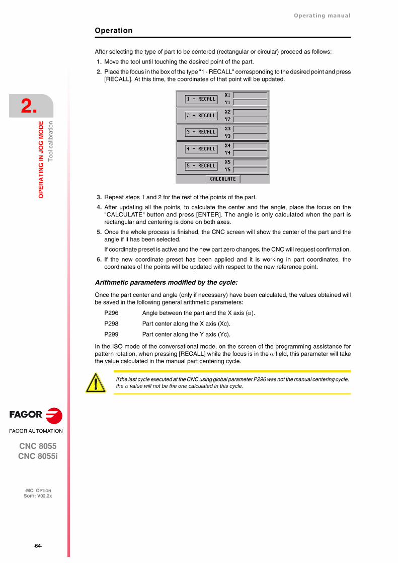
·64·
Operating manual
CNC 8055CNC 8055i
2.
OP
ER
AT
ING
IN J
OG
MO
DE
·MC· OPTIONSOFT: V02.2X
Too
l cal
ibra
tion
Operation
After selecting the type of part to be centered (rectangular or circular) proceed as follows:
1. Move the tool until touching the desired point of the part.
2. Place the focus in the box of the type "1 - RECALL" corresponding to the desired point and press[RECALL]. At this time, the coordinates of that point will be updated.
3. Repeat steps 1 and 2 for the rest of the points of the part.
4. After updating all the points, to calculate the center and the angle, place the focus on the"CALCULATE" button and press [ENTER]. The angle is only calculated when the part isrectangular and centering is done on both axes.
5. Once the whole process is finished, the CNC screen will show the center of the part and theangle if it has been selected.
If coordinate preset is active and the new part zero changes, the CNC will request confirmation.
6. If the new coordinate preset has been applied and it is working in part coordinates, thecoordinates of the points will be updated with respect to the new reference point.
Arithmetic parameters modified by the cycle:
Once the part center and angle (only if necessary) have been calculated, the values obtained willbe saved in the following general arithmetic parameters:
P296 Angle between the part and the X axis ().
P298 Part center along the X axis (Xc).
P299 Part center along the Y axis (Yc).
In the ISO mode of the conversational mode, on the screen of the programming assistance forpattern rotation, when pressing [RECALL] while the focus is in the field, this parameter will takethe value calculated in the manual part centering cycle.
If the last cycle executed at the CNC using global parameter P296 was not the manual centering cycle,the value will not be the one calculated in this cycle.

Operating manual
CNC 8055CNC 8055i
OP
ER
AT
ING
IN J
OG
MO
DE
2.
·MC· OPTIONSOFT: V02.2X
·65·
Too
l cal
ibra
tion
2.7.5 Tabletop probe calibration (level 4)
The new tabletop probe calibration cycle level 4 makes probe calibration easier. This reducesmachine preparation time.
The tool used for calibration must properly calibrated in radius and length.
Data to be entered
[ T ] Tool number
It defines the number of the tool used to calibrate the probe. If not programmed or programmed witha 0 value, the CNC will display the corresponding error message.
[ D ] Tool offset number
It defines the tool offset number. If not programmed, it assumes the offset number assigned to Tin the tool table.
[ Ds ] Approach distance
Probe approaching distance in each probing movement. If not programmed or programmed witha 0 value, the CNC will display the corresponding error message.
[ Dr ] Withdrawal distance
Distance the tool retracts after touching the probe to take the measurement. If not programmed orprogrammed with a 0 value, the CNC will display the corresponding error message.
[ Fs ] Searching feedrate
Probe searching feedrate. If not programmed or programmed with a 0 value, the CNC will displaythe corresponding error message.
[ F ] Measuring feedrate
Measuring feedrate. If not programmed or programmed with a 0 value, the CNC will display thecorresponding error message.
Type of calibration
Z
Y
X
Ds
Ds
It indicates whether the calibration is simple or double.
• Single calibration: the calibration is carried out in the 4 quadrants of the probewith the spindle that holds the tool oriented at 0º.
• Double calibration: the calibration is carried out twice in the 4 quadrants of theprobe, one with the spindle positioned at 0º and the other with the spindlepositioned at 180º. This prevents tool eccentricity errors.

·66·
Operating manual
CNC 8055CNC 8055i
2.
OP
ER
AT
ING
IN J
OG
MO
DE
·MC· OPTIONSOFT: V02.2X
Too
l cal
ibra
tion
Programming method for probe coordinates
It indicates whether the cycle assumes the probe position defined in the machine parameters or theposition defined in the cycle. To select one of them, use the cursor to select the "Machine parameters/ Programmable parameters" box and press the two-color key.
Machine parameters: The cycle assumes the probe position defined in the machineparameters.
Programmed parameters: The cycle assumes the probe position defined in the cycle (Xmax,Xmin, Ymax, Ymin, Zmax, Zmin).
[ Xmax ] Approximate X axis coordinate of the most positive side of the probe
Approximate coordinate of the most positive side of the probe, along the abscissa axis. If notprogrammed, it will assume the value of general machine parameter PRBXMAX (P41).
[ Xmin ] Approximate X axis coordinate of the least positive side of the probe
Approximate coordinate of the least positive side of the probe, along the abscissa axis. If notprogrammed, it will assume the value of general machine parameter PRBXMIN (P40).
[ Ymax ] Approximate Y axis coordinate of the most positive side of the probe
Approximate coordinate of the most positive side of the probe, along the ordinate axis. If notprogrammed, it will assume the value of general machine parameter PRBYMAX (P43).
[ Ymin ] Approximate Y axis coordinate of the least positive side of the probe
Approximate coordinate of the least positive side of the probe, along the ordinate axis. If notprogrammed, it will assume the value of general machine parameter PRBYMIN (P42).
[ Zmax ] Approximate Z axis coordinate of the most positive side of the probe
Approximate coordinate of the most positive side of the probe, along the Z axis. If not programmed,it will assume the value of general machine parameter PRBZMAX (P45).
[ Zmin ] Approximate Z axis coordinate of the least positive side of the probe
Approximate coordinate of the least positive side of the probe, along the Z axis. If not programmed,it will assume the value of general machine parameter PRBZMIN (P44).
Arithmetic parameters modified by the cycle
Once the cycle has been completed, the CNC will return the real values obtained aftermeasurement, in the following global arithmetic parameters.
P295 Real coordinate of the least positive side of the probe, along the abscissa axis.
P296 Real coordinate of the most positive side of the probe, along the abscissa axis.
P297 Real coordinate of the least positive side of the probe, along the ordinate axis.
P298 Real coordinate of the most positive side of the probe, along the ordinate axis.
P299 Real coordinate of the measured probe side along the longitudinal axis.

Operating manual
CNC 8055CNC 8055i
OP
ER
AT
ING
IN J
OG
MO
DE
2.
·MC· OPTIONSOFT: V02.2X
·67·
Spi
ndle
con
trol
2.8 Spindle control
The standard screen of the MC mode offers the following spindle data.
1. Real spindle speed in rpm.
2. Theoretical spindle speed in rpm.
To select another speed, press the [S] key. The CNC highlights the current value.
Enter the new value and press [START]. The CNC assumes that value and refreshes the realspindle speed.
The maximum spindle speed is saved in the MDISL variable. This variable is updated (refreshed)when programming function "G92 S" via ISO.
3. Percentage of the theoretical spindle speed being applied.
To modify the percentage (%), press the following keys.
4. Spindle status:
To modify the spindle status, press the following keys:
Spindle clockwise,
Spindle counterclockwise
Spindle stopped.

·68·
Operating manual
CNC 8055CNC 8055i
2.
OP
ER
AT
ING
IN J
OG
MO
DE
·MC· OPTIONSOFT: V02.2X
Con
trol
ling
the
exte
rnal
dev
ices
2.9 Controlling the external devices
With this CNC, it is possible to activate and deactivate, via keyboard, up to 6 external devices, forexample, the coolant.
The machine manufacturer must use the PLC program to activate and deactivate the devices. TheCNC will inform the PLC about the status of each key. The corresponding register bit will be set to1 when the key is pressed and 0 when it is not pressed.
The register bit for each key is:
The status of the lamp of each key must be controlled by the machine manufacturer through thePLC program using the input variables TCLED* indicated in the figure.
Examples:
Coolant control:
DFU B28R561 = CPL TCLED1 = CPL O33
Tailstock control (O1). A number of conditions must be met for activating or deactivating thetailstock, such as spindle stopped, etc.
DFU B30R561 AND (Rest of conditions) = CPL TCLED2 = CPL O34

Operating manual
CNC 8055CNC 8055i
OP
ER
AT
ING
IN J
OG
MO
DE
2.
·MC· OPTIONSOFT: V02.2X
·69·
ISO
man
agem
ent
2.10 ISO management
Access to the MDI mode or the ISO mode.
The ISO key may be used to access the MDI mode or the ISO mode.
To access the MDI mode, the CNC must be in jog mode and the ISO key must be pressed. The CNCwill show a window at the bottom of the standard (or special) screen.
In this window, it is possible to edit a block in ISO code and then execute it, like in MDI in M mode.
Displaying the last 10 MDI instructions.
From the MDI mode, pressing the [UP ARROW] or [DOWN ARROW] key opens a window that showsthe last 10 instructions that have been executed. This window resizes itself to fit the number ofinstructions that have been saved.
To execute or modify an MDI line that has been executed earlier, proceed as follows:
• Go into MDI mode.
• Press the [UP ARROW] or [DOWN ARROW] key to open the window that shows the last MDIinstructions (up to 10).
• Use the [UP ARROW] or [DOWN ARROW] key to select the desired instruction.
Press [START] to execute the selected instruction.
Press [ENTER] to modify the selected instruction. Once the instruction has been modified,press [START] to execute it.
Considerations.
• An MDI instruction is saved only if it is correct and if it is not the same as the previous one onthe list.
• The instructions are kept saved even after turning the unit off.
Generating an ISO-coded program
In the conversational mode of the CNC, it is possible to generate an ISO-coded program from anoperation (cycle) or on a part-program. See "6.5 Graphic representation" on page 154.

·70·
Operating manual
CNC 8055CNC 8055i
2.
OP
ER
AT
ING
IN J
OG
MO
DE
·MC· OPTIONSOFT: V02.2X
ISO
man
agem
ent

CNC 8055CNC 8055i
·MC· OPTIONSOFT: V02.2X
3
·71·
WORKING WITH OPERATIONS OR CYCLES
Use the following CNC keys to select the different machining operations or cycles.
User cycles
The user cycle is edited like any other standard cycle of the MC mode. Once all the required datahas been defined, the user can simulate or execute the cycle like any other standard cycle of theMC mode.
Cycles or operations of the CNC
When pressing any other key, the CNC selects the corresponding standard machining cycle,changes the display and turns on the lamp of the key that has been pressed (indicating the selectedtype.
Standard machining operations or cycles may be selected with each one of the following keys:
When pressing [PCALL], the CNC shows all the user cycles defined by the machinemanufacturer with the WGDRAW application.
Boring. Surface milling and slot milling.
Reaming. Pocket with profile (2D and 3D).
Tapping. Rectangular and circular boss.
Drilling and center punching. Rectangular and circular pocket.
Profile milling. Positioning.
When the machining operation or cycle has several levels, [LEVEL CYCLE] must bepressed to select the desired cycle level.

·72·
Operating manual
CNC 8055CNC 8055i
3.
WO
RK
ING
WIT
H O
PE
RA
TIO
NS
OR
CY
CL
ES
·MC· OPTIONSOFT: V02.2X
Some cycles may be carried out in the tool position or may be associated a multiple positioning sothe cycle may be repeated in several locations. The positioning moves may be selected with eachone of the following keys:
It is possible to combine ISO-coded blocks with standard and/or user cycles to create part-programs.Chapter "5 Saving programs"describes in detail how to do it and how to use those programs.
To de-select a cycle and return to the standard screen, press the key for the selected cycle (the onewith the lamp on) or the [ESC] key.
Multiple positioning in several locations.
Multiple positioning in a straight line.
Multiple positioning in an arc.
Multiple positioning in a rectangular pattern.
Multiple positioning in a grid pattern.
When operating in conversational mode, do not use global parameters 150 through 299 (bothincluded), because the operations or cycles can modify these parameters and cause the machine tomalfunction.

Operating manual
CNC 8055CNC 8055i
WO
RK
ING
WIT
H O
PE
RA
TIO
NS
OR
CY
CL
ES
3.
·MC· OPTIONSOFT: V02.2X
·73·
Ope
ratio
n ed
iting
mod
e
3.1 Operation editing mode
Once the operation has been selected, the CNC shows a screen like the following:
1. Name of the selected operation or work cycle.
2. Help graphics.
3. When it is a positioning operation, indicates its associated operation.
4. Current machine status. Coordinates and machining conditions.
5. Data defining the machining geometry.
6. Machining conditions for the operation.
The CNC will highlight an icon, a coordinate or one of the data defining the operation or cycleindicating that it has been selected. Use the following keys to select another icon, data or coordinate.
The CNC selects the previous one or the next one.
The CNC selects the first coordinate for that axis. Pressing that key again selectsthe next coordinate for that axis.
The CNC selects the corresponding roughing data. Pressing that key again selectsthe corresponding finishing data.
The CNC selects the "S" roughing data. Pressing that key again selects the "S"finishing data.

·74·
Operating manual
CNC 8055CNC 8055i
3.
WO
RK
ING
WIT
H O
PE
RA
TIO
NS
OR
CY
CL
ES
·MC· OPTIONSOFT: V02.2X
Ope
ratio
n ed
iting
mod
e
3.1.1 Definition of machining conditions
Some operations keep the machining conditions throughout the execution (boring, reaming, etc.).Other operations use some machining conditions for roughing and others for finishing (pockets,bosses, etc.).
This section describes how to define all this data.
Selecting the roughing operation.
Place the cursor on the roughing checkbox, select or de-select the roughing operation pressing the[TWO-COLOR] key and press [ENTER]. When de-selecting the roughing, all its data will stay in gray.
The data for finishing "side stock" and "depth stock" is turned on/off using the roughing checkbox
Selecting the finishing operation.
Place the cursor on the finishing checkbox, select or de-select the finishing operation pressing the[TWO-COLOR] key and press [ENTER]. When de-selecting the finishing, all its data will stay in gray.
Axis feedrate (F).
Spindle turning speed (S).
Spindle turning direction
Machining tool (T).
Place the cursor over this data, key in the desired value and press [ENTER].
Press [ESC] to quit the tool calibration mode and return to the cycle
Coolant.
There are two ways to turn the coolant on or off.
Once the operation or the cycle is completed or the part-program it belongs to, the CNC outputsthe M9 function to the PLC.
Roughing pass ().
Finishing stocks (, z).
Place the cursor over this data, key in the desired value and press [ENTER].
Place the cursor over this data, key in the desired value and press [ENTER].
Place the cursor on this data and press the two-color key.
It is also possible to access the tool calibration mode to check or modify the data for theselected tool. To do that, place the cursor on the "T" and press the key associated withtool calibration.
Place the cursor on this data and press the two-color key to change the icon.
Turns the coolant on. The CNC outputs the M8 function to the PLC.
Turns the coolant off. The CNC outputs the M9 function to the PLC.
Place the cursor over this data, key in the desired value and press [ENTER].
Place the cursor over this data, key in the desired value and press [ENTER].
*

Operating manual
CNC 8055CNC 8055i
WO
RK
ING
WIT
H O
PE
RA
TIO
NS
OR
CY
CL
ES
3.
·MC· OPTIONSOFT: V02.2X
·75·
Ope
ratio
n ed
iting
mod
e
3.1.2 Safety plane
There are four work planes in all operations:
• Starting plane or position occupied by the tool when calling the cycle. It is not defined; the CNCsets it.
• Safety plane. It is used for the first approach and for withdrawing the tool after the machiningoperation. It is set with parameter Zs.
• Part approaching plane. The CNC calculates it, at 1 mm from the part surface.
• Part surface. It is set with parameter Z.
The tool moves in rapid (G00) to the safety plane (Zs), moves on in rapid to the approach plane (upto 1 mm off the part surface) and then moves at machining feedrate (G01) up to the part surface.
Approach to the part surface
The approach to the part surface depends on the current tool position.
• If it is above the safety plane (left figure), it first moves in X, Y and then in Z.
• If it is below the safety plane (right figure), it first moves in Z to the safety plane, then in X, Y andfinally in Z to the part surface.

·76·
Operating manual
CNC 8055CNC 8055i
3.
WO
RK
ING
WIT
H O
PE
RA
TIO
NS
OR
CY
CL
ES
·MC· OPTIONSOFT: V02.2X
Ope
ratio
n ed
iting
mod
e
3.1.3 Cycle level
All the cycles have several editing levels. Each level has its own screen and the main window of thecycle indicates, with tabs, the available levels and which one is selected.
To change levels, use the [LEVEL CYCLE] key or the [page up] and [page down] keysto scroll up and down through the various levels.

Operating manual
CNC 8055CNC 8055i
WO
RK
ING
WIT
H O
PE
RA
TIO
NS
OR
CY
CL
ES
3.
·MC· OPTIONSOFT: V02.2X
·77·
Sim
ulat
ing
and
exec
utin
g th
e op
erat
ion
3.2 Simulating and executing the operation
All the operations or cycles have 2 work modes; execution and editing.
• Press [ESC] to switch from editing mode to execution mode.
• Press [ESC] to switch from executing mode to editing mode.
For further information on simulating and executing cycles, see the chapter "6 Execution andsimulation".
The operation or cycle may be simulated in either mode. To do that, press the[GRAPHICS] key.
To execute the operation or cycle, select the execution mode and press [START].
Editing mode Execution mode

·78·
Operating manual
CNC 8055CNC 8055i
3.
WO
RK
ING
WIT
H O
PE
RA
TIO
NS
OR
CY
CL
ES
·MC· OPTIONSOFT: V02.2X
Sim
ulat
ing
and
exec
utin
g th
e op
erat
ion
3.2.1 Background cycle editing
It is possible to edit an operation or cycle while executing a program or part (background editing).The new operation edited may be saved as part of a part-program other than the one being executed.
The operation being edited in background cannot be executed or simulated, and the current positionof the machine cannot be assigned to a coordinate.
Use the following keys to inspect or change a tool while editing in background.
Pressing the [T] key without quitting background editing selects the T field of the operation or of thecanned cycle being edited.
Interrupts the execution and goes on editing in background.
To quit background editing.
To access tool inspection.
Background editing is not possible while executing an independent operation or cycle. It can only bedone while executing a program or part.i

Operating manual
CNC 8055CNC 8055i
WO
RK
ING
WIT
H O
PE
RA
TIO
NS
OR
CY
CL
ES
3.
·MC· OPTIONSOFT: V02.2X
·79·
Pro
file
mill
ing
oper
atio
n
3.3 Profile milling operation
This cycle may be defined in two ways:
Level 1.
The following data must be defined:
• The starting point (X1, Y1), the intermediate points (P1 through P12), the last point (Xn, Yn) andthe machining conditions in Z (Zs, Z, P, I, Fz).
• Also, in the area for roughing operation data, it must be defined whether the milling operationis carried out with or without tool compensation.
Level 2.
The following data must be defined:
• The starting point (X, Y), the "Profile program" number and the machining conditions in Z (Zs,Z, P, I, Fz).
• Also, in the area for roughing operation data, it must be defined whether the milling operationis carried out with or without tool compensation.
This key accesses the profile milling operation.

·80·
Operating manual
CNC 8055CNC 8055i
3.
WO
RK
ING
WIT
H O
PE
RA
TIO
NS
OR
CY
CL
ES
·MC· OPTIONSOFT: V02.2X
Pro
file
mill
ing
oper
atio
n
3.3.1 Definition of data
Coordinates of the first and last points.
The coordinates are defined one by one. After placing the cursor on the coordinates of the axes tobe defined, the value is entered in one of the following ways.
• Entering the value manually. Key in the desired value and press [ENTER].
• Assign the current machine position.
Jog the axis with the handwheel or the JOG keys up to the desired point. Press [RECALL] sothe selected data assumes the value shown in the top right window and press [ENTER].
The top right window shows the tool position at all times.
Intermediate points (level 1).
The intermediate points are defined one by one. When not using the 12 definition points, the firstunused point must be defined with the same coordinates as the last point of the profile.
The following must be defined for each point.
If a coordinate is left blank, the cycle will assume that it is the same as that of the previous one.
The coordinates of each point may also be defined incrementally. To do that, select the desiredcoordinate with the cursor and press the two-color key. Both coordinates of the selected point willbe shown preceded by the "" icon that indicates the incremental value with respect to the previouspoint.
Deleting all the points of a profile.
Once all the desired points have been programmed, they may all be erased at once. To delete allthe programmed points at the same time, proceed as follows:
• Place the cursor on the text "DEF. PROFILE (max 12 points)" of the window where the pointsare edited.
• In the instant the cursor is placed in this position, the text changes to: "CLEAR - Delete all thepoints".
• At this moment, pressing [CLEAR] displays a window requesting confirmation to delete all thepoints: Press the [ENTER] to delete all the points or [ESC] not to delete them.
• The X, Y coordinates are defined one by one like the coordinates of the first and lastpoints.
• Type of corner. To select the type of corner, place the cursor over this icon and pressthe two-color key.
If defined... The CNC assumes...
X1 25.323 Y1 26.557 Point: X1 25.323 Y1 26.557
X2 Y2 78.998 Point: X2 25.323 Y2 78.998
X3 67.441 Y3 83.231 Point: X3 67.441 Y3 83.231
X4 Y4 Point: X4 67.441 Y4 83.231
X5 Y5 There are no more points, it is a repetition of the previouspoint.

Operating manual
CNC 8055CNC 8055i
WO
RK
ING
WIT
H O
PE
RA
TIO
NS
OR
CY
CL
ES
3.
·MC· OPTIONSOFT: V02.2X
·81·
Pro
file
mill
ing
oper
atio
n
Machining conditions in Z (Zs, Z, P, I, Fz).
The machining conditions are defined one by one.
• The Zs and Z values are defined as the coordinates of the first and last points.
• To define the rest of the values (P, I, Fz), go to the corresponding window, key in the desired valueand press [ENTER].
If the penetration step is programmed with a positive sign (I+), the cycle recalculates the stepso all the penetrations are identical, this being equal to or less than the one programmed. Ifprogrammed with a negative sign (I-), the cycle is machined with the given pass (step) exceptthe last pass that machines the rest.
Milling with or without tool radius compensation.
To select the type of corner, place the cursor over this icon and press the two-color key.
Without tool radius Compensation.
With left-hand tool radius compensation.
With right-hand tool radius compensation.

·82·
Operating manual
CNC 8055CNC 8055i
3.
WO
RK
ING
WIT
H O
PE
RA
TIO
NS
OR
CY
CL
ES
·MC· OPTIONSOFT: V02.2X
Pro
file
mill
ing
oper
atio
n
3.3.2 Profile definition (level 2)
Defining the profile program.
The profile program may be defined as follows.
• Key in the profile program number directly.
If the "profile program" is known, key in the program number and press [ENTER].
• Access the "profile programs" to select one of them.
Press the [] key. The canned cycle will show a window with the profile programs currentlydefined. Use the [] and [] keys to move around this window. After positioning the cursor onthe desired program, press [ENTER].
To exit this window without selecting any program, use the [] y [] keys.
Editing a new profile program.
To edit a new profile program, key in the program number (between 0 and 999) and press [RECALL].The CNC will show the window for the profile editor (see operating manual).
After editing the profile, the CNC requests the comment to be associated with the "Profile program"that has been edited. Enter the desired comment and press [ENTER]. If no comment is desired,press [ESC].
Copying a profile program.
Press the [] key. The canned cycle will show the profile programs currently defined. Place thecursor on the profile program to be copied and press [P.PROG]. The CNC requests the number ofthe new profile and it allows changing its comment. If the number entered is the same as that ofan existing profile, the CNC requests confirmation to replace it.
Modify an already existing "Profile program".
To modify a profile program, key in the program number and press [RECALL]. The CNC will show,in the window for the profile editor, the profile that is currently defined.
With this profile, the following actions are possible:
• Add new items at the end of the present profile.
• Modifying the data of any element.
• Modify or include chamfers, rounded corners, etc.
• Deleting elements of the profile.
Deleting an existing profile program.
Press the [] key. The canned cycle will show the profile programs currently defined. Place thecursor on the profile program to be deleted and press [CLEAR]. The CNC requests confirmation.
The profile programs can also be accessed in the "M" mode because the CNC saves them internallyas P997xxx.Example: Profile program 123 is internally saved as P997123.When saving a part-program that contains a level-2 profile cycle into an external device, PC, floppydrive, etc. also save its associated profile program P997xxx.
i

Operating manual
CNC 8055CNC 8055i
WO
RK
ING
WIT
H O
PE
RA
TIO
NS
OR
CY
CL
ES
3.
·MC· OPTIONSOFT: V02.2X
·83·
Sur
face
mill
ing
and
slot
mill
ing
oper
atio
ns
3.4 Surface milling and slot milling operations
Surface milling operation.
The following data must be defined:
• The type of surface milling, the starting point (X1, Y1), the dimensions of the surface milling (L,H, E,) and the machining conditions in Z (Zs, Z, P, I, Fz).
• Also, you must define the milling pass () in the data area for the roughing operation and thefinishing stock (z) in the data area for the finishing operation.
Grooving operation.
The following data must be defined:
• The type of slot milling, the starting point (X1, Y1), the dimensions of the slot (L, H, E, ) andthe machining conditions in Z (Zs, Z, P, I, Fz).
This key accesses the surface milling and slot milling operations.
• In the roughing area, define the milling pass () and the machining direction.
• In the finishing area, define the finishing stocks ( and z), the number of finishingpasses and the machining direction.

·84·
Operating manual
CNC 8055CNC 8055i
3.
WO
RK
ING
WIT
H O
PE
RA
TIO
NS
OR
CY
CL
ES
·MC· OPTIONSOFT: V02.2X
Sur
face
mill
ing
and
slot
mill
ing
oper
atio
ns
3.4.1 Defining the surface milling data
Type of surface milling.
Coordinates of starting point (X1, Y1).
Define one of the corners of the surface to be milled (X1, Y1). The coordinates are defined one byone. After placing the cursor on the coordinates of the axes to be defined, the value is entered inone of the following ways.
• Entering the value manually. Key in the desired value and press [ENTER].
• Assign the current machine position.
Jog the axis with the handwheel or the JOG keys up to the desired point. Press [RECALL] sothe selected data assumes the value shown in the top right window and press [ENTER].
The top right window shows the tool position at all times.
Surface to be milled (L, H, E, ).
After defining one of the corners (X1, Y1), define the length (L) and width (H) of the surface to bemilled. The sign of the L and H indicates the orientation referred to the X1, Y1 point.
Once the surface to be milled has been defined, the icon shown at the bottom right (roughing andfinishing area) may be used to select the corner to start milling the surface.
• The data E and are defined one by one. Place the cursor in the corresponding window, keyin the desired value and press [ENTER].
When programming parameter "E" with a value smaller than the tool radius, the CNC executesthe surface milling with an "E" value equal to the tool radius.
Machining conditions in Z (Zs, Z, P, I, Fz).
The machining conditions are defined one by one.
• The Zs and Z values are defined as the coordinates of the first and last points.
• To define the rest of the values (P, I, Fz), go to the corresponding window, key in the desired valueand press [ENTER].
If the penetration step is programmed with a positive sign (I+), the cycle recalculates the stepso all the penetrations are identical, this being equal to or less than the one programmed. Ifprogrammed with a negative sign (I-), the cycle is machined with the given pass (step) exceptthe last pass that machines the rest.
Milling pass () and finishing stock (z).
These data are defined one by one. Place the cursor in the corresponding window, key in the desiredvalue and press [ENTER].
Type of surface milling.
To select the type of surface milling, place the cursor over this icon and press the two-color key.

Operating manual
CNC 8055CNC 8055i
WO
RK
ING
WIT
H O
PE
RA
TIO
NS
OR
CY
CL
ES
3.
·MC· OPTIONSOFT: V02.2X
·85·
Sur
face
mill
ing
and
slot
mill
ing
oper
atio
ns
3.4.2 Defining the grooving data
Type of grooving.
Coordinates of the starting point.
The coordinates are defined one by one. After placing the cursor on the coordinates of the axes tobe defined, the value is entered in one of the following ways.
• Entering the value manually. Key in the desired value and press [ENTER].
• Assign the current machine position.
Jog the axis with the handwheel or the JOG keys up to the desired point. Press [RECALL] sothe selected data assumes the value shown in the top right window and press [ENTER].
The top right window shows the tool position at all times.
Dimensions of the slot (L, H, E, ).
These data are defined one by one. Place the cursor in the corresponding window, key in the desiredvalue and press [ENTER].
When programming parameter "E" with a value smaller than the tool radius, the CNC executes theslot milling with an "E" value equal to the tool radius.
Machining conditions in Z (Zs, Z, P, I, Fz).
The machining conditions are defined one by one.
• The Zs and Z values are defined as the coordinates of the first and last points.
• To define the rest of the values (P, I, Fz), go to the corresponding window, key in the desired valueand press [ENTER].
If the penetration step is programmed with a positive sign (I+), the cycle recalculates the stepso all the penetrations are identical, this being equal to or less than the one programmed. Ifprogrammed with a negative sign (I-), the cycle is machined with the given pass (step) exceptthe last pass that machines the rest.
Milling pass () and finishing stock (z).
These data are defined one by one. Place the cursor in the corresponding window, key in the desiredvalue and press [ENTER].
Type of grooving.
To select the type of grooving, place the cursor over this icon and press the two-color key.

·86·
Operating manual
CNC 8055CNC 8055i
3.
WO
RK
ING
WIT
H O
PE
RA
TIO
NS
OR
CY
CL
ES
·MC· OPTIONSOFT: V02.2X
Sur
face
mill
ing
and
slot
mill
ing
oper
atio
ns
Clockwise milling of the different types of slots .

Operating manual
CNC 8055CNC 8055i
WO
RK
ING
WIT
H O
PE
RA
TIO
NS
OR
CY
CL
ES
3.
·MC· OPTIONSOFT: V02.2X
·87·
Poc
ket c
ycle
with
a p
rofil
e
3.5 Pocket cycle with a profile
A pocket is composed by an external contour or profile (1) and a series of internal contours or profiles(2). These internal profiles are called islands.
• In 2D pockets (top left figure), all the walls of the outside profile and of the islands are vertical.
• In 3D pockets (top right figure), one, several or all the walls of the outside pocket and/or of theislands are not vertical (up to a maximum of 4).
Programming 2D pockets with profile.
When defining the profile, one must indicate, besides the outside contour of the pocket, the contouror contours of the islands.
The machining in Z is defined with the following parameters:
Zs Safety plane coordinate.
Z Part surface coordinate.
P Pocket depth.
I Step in Z.
Fz Penetrating feedrate in Z.
The following must be defined in the data area for the roughing operation:
The sideways penetration angle.
The milling pass.
The following must be defined in the data area for the finishing operation:
The sideways penetration angle.
Finishing stock on the side walls.
z Finishing stock at the bottom.
N Number of finishing passes in Z.
This key accesses the pocket-with-profile operation.
There are two types of pocket with profile; 2D and 3D.
Pocket with 2D profile Pocket with 2D profile

·88·
Operating manual
CNC 8055CNC 8055i
3.
WO
RK
ING
WIT
H O
PE
RA
TIO
NS
OR
CY
CL
ES
·MC· OPTIONSOFT: V02.2X
Poc
ket c
ycle
with
a p
rofil
e
Programming 3D pockets with profile.
Pocket identification number (POCK. 3D).
Several 3D pockets are possible. The CNC associates to each 3D pocket all its data (surfaceprofile, depth profile, machining conditions, etc.).
Surface profile or profile in the XY plane. Profile (P. XY).
One must indicate, besides the outside contour of the pocket, the contour or contours of thepossible islands.
Depth profile for the first profile defined. Profile (P. Z1).
They usually correspond to the outside contour of the pocket.
Depth profile for the second profile defined. Profile (P. Z2).
They usually correspond to the contour of the first island defined.
Depth profile for the third profile defined. Profile (P. Z3).
They usually correspond to the contour of the second island defined.
Depth profile for the fourth profile defined. Profile (P. Z4).
They usually correspond to the contour of the third island defined.
The machining in Z is defined with the following parameters:
Zs Safety plane coordinate.
Z Part surface coordinate.
P Pocket depth.
I1 Roughing step in Z.
Fz Penetrating feedrate in Z.
I2 Semi-finishing step in Z.
The following must be defined in the data area for the roughing operation:
The sideways penetration angle.
The milling pass.
The following must be defined in the data area for the finishing operation:
R Tool tip radius.
Finishing stock on the side walls.
Finishing pass.
Once all the profiles have been defined, the configuration of the 3D pocket mustbe validated. To do that, place the cursor on the icon (a) and press [ENTER] tovalidate the pocket. The cycle will show the icon (b).
Direction of the finishing passes on the walls.
(a) (b)
The pocket configuration program and the profile programs can also be accessed in the "M" modebecause the CNC saves them internally as:P995xxx - 3D pocket configuration.P998xxx - The profiles of the XY plane, both in 2D and 3D pockets.P996xxx - The depth profiles of the 3D pockets.
i

Operating manual
CNC 8055CNC 8055i
WO
RK
ING
WIT
H O
PE
RA
TIO
NS
OR
CY
CL
ES
3.
·MC· OPTIONSOFT: V02.2X
·89·
Poc
ket c
ycle
with
a p
rofil
e
3.5.1 Definition of data
Machining conditions in Z (Zs, Z).
To define the values (Zs and Z), after going to the corresponding window, the value is entered inone of the following ways.
• Entering the value manually. Key in the desired value and press [ENTER].
• Assign the current machine position.
Jog the axis with the handwheel or the JOG keys up to the desired point. Press [RECALL] sothe selected data assumes the value shown in the top right window and press [ENTER].
The top right window shows the tool position at all times.
Machining conditions in Z (P, Fz, I, I1, I2).
The machining conditions are defined one by one.
• To define the values (P, Fz, I, I1, I2), go to the corresponding window, key in the desired valueand press [ENTER].
If the penetration step is programmed with a positive sign (I+), the cycle recalculates the stepso all the penetrations are identical, this being equal to or less than the one programmed. Ifprogrammed with a negative sign (I-), the cycle is machined with the given pass (step) exceptthe last pass that machines the rest.
Milling pass () and finishing pass ().
Place the cursor in the corresponding window, roughing or finishing operation, key in the desiredvalue and press [ENTER].
Sideways penetration angle (, ).
Place the cursor in the corresponding window, roughing or finishing operation, key in the desiredvalue and press [ENTER].
Finishing stock on the side walls () and at the bottom (z).
Place the cursor in the corresponding window, finishing operation, key in the desired value and press[ENTER].
Finishing tool tip radius (R).
Place the cursor in the corresponding window, finishing operation, key in the desired value and press[ENTER].
Direction of the finishing passes on the walls.
To select the direction of the finishing passes on the walls, place the cursorover this icon and press the two-color key.

·90·
Operating manual
CNC 8055CNC 8055i
3.
WO
RK
ING
WIT
H O
PE
RA
TIO
NS
OR
CY
CL
ES
·MC· OPTIONSOFT: V02.2X
Poc
ket c
ycle
with
a p
rofil
e
3.5.2 Profile definition
Defining the profile program.
The profile program may be defined as follows.
• Key in the profile program number directly.
If the "profile program" is known, key in the program number and press [ENTER].
• Access the "profile programs" to select one of them.
Press the [] key. The canned cycle will show a window with the profile programs currentlydefined. There are 3 different directories, one for the pocket configuration profiles, another onefor the profiles in the XY plane and another one for the depth profiles Use the [] and [] keysto move around this window. After positioning the cursor on the desired program, press [ENTER].
To exit this window without selecting any program, use the [] y [] keys.
Editing a new profile program.
To edit a new profile program, key in the program number (between 0 and 999) and press [RECALL].The CNC will show the window for the profile editor (see operating manual).
After editing the profile, the CNC requests the comment to be associated with the "Profile program"that has been edited. Enter the desired comment and press [ENTER]. If no comment is desired,press [ESC].
Copying a profile program.
Press the [] key. The canned cycle will show the profile programs currently defined. Place thecursor on the profile program to be copied and press [P.PROG]. The CNC requests the number ofthe new profile and it allows changing its comment. If the number entered is the same as that ofan existing profile, the CNC requests confirmation to replace it.
Modify an already existing "Profile program".
To modify a profile program, key in the program number and press [RECALL]. The CNC will show,in the window for the profile editor, the profile that is currently defined.
With this profile, the following actions are possible:
• Add new items at the end of the present profile.
• Modifying the data of any element.
• Modify or include chamfers, rounded corners, etc.
• Deleting elements of the profile.
Deleting an existing profile program.
Press the [] key. The canned cycle will show the profile programs currently defined. Place thecursor on the profile program to be deleted and press [CLEAR]. The CNC requests confirmation.
The profile programs can also be accessed in the "M" mode because the CNC saves them internally as:P995xxx - 3D pocket configuration.P998xxx - The profiles of the XY plane, both in 2D and 3D pockets.P996xxx - The depth profiles of the 3D pockets.When saving a part-program that contains a pocket-with-profile cycle into an external device, PC,floppy drive, etc. also save its associated profile programs.
i

Operating manual
CNC 8055CNC 8055i
WO
RK
ING
WIT
H O
PE
RA
TIO
NS
OR
CY
CL
ES
3.
·MC· OPTIONSOFT: V02.2X
·91·
Poc
ket c
ycle
with
a p
rofil
e
3.5.3 Profile definition examples
Example of how to define a 2D profile without islands:
2D pocket.
Configuration.
Profile.
Corners.
End.
Save profile.
Profile 1 [RECALL]
Abscissa axis: X Ordinate axis: Y
Autozoom: Yes Validate
Initial point X 20 Y -8 Validate
Straight line X 20 Y -40 Validate
Straight line X 145 Y -40 Validate
Straight line X 145 Y -25 Validate
Clockwise arc Xf 145 Yf 25 R 25 Validate
Straight line X 145 Y 40 Validate
Straight line X 20 Y 40 Validate
Straight line X 20 Y 8 Validate
Straight line X 55 Y 8 Validate
Straight line X 55 Y -8 Validate
Straight line X 20 Y -8 Validate
Lower left corner [ENTER] Chamfer 15 [ENTER]
Upper left corner [ENTER] Chamfer 15 [ENTER]
[ESC]

·92·
Operating manual
CNC 8055CNC 8055i
3.
WO
RK
ING
WIT
H O
PE
RA
TIO
NS
OR
CY
CL
ES
·MC· OPTIONSOFT: V02.2X
Poc
ket c
ycle
with
a p
rofil
e
Example of how to define a 2D profile with islands:
2D pocket.
Configuration.
Profile (outside profile).
Corners.
New profile (island).
End.
Save profile.
Profile 2 [RECALL]
Abscissa axis: X Ordinate axis: Y
Autozoom: Yes Validate
Initial point X 20 Y 0 Validate
Straight line X 20 Y -40 Validate
Straight line X 145 Y -40 Validate
Straight line X 145 Y 40 Validate
Straight line X 20 Y 40 Validate
Straight line X 20 Y 0 Validate
Lower left corner [ENTER] Chamfer 15 [ENTER]
Lower right corner [ENTER] Chamfer 15 [ENTER]
Upper right corner [ENTER] Chamfer 15 [ENTER]
Upper left corner [ENTER] Chamfer 15 [ENTER]
[ESC]
Profile
Initial point X 115 Y -25 Validate
Straight line X 115 Y 0 Validate
Clockwise arc Xf 90 Yf 25 Xc 115 Yc 25 R 25 Validate
Straight line X 50 Y 25 Validate
Straight line X 50 Y 0 Validate
Clockwise arc Xf 75 Yf -25 Xc 50 Yc -25 R 25 Validate
Straight line X 115 Y -25 Validate

Operating manual
CNC 8055CNC 8055i
WO
RK
ING
WIT
H O
PE
RA
TIO
NS
OR
CY
CL
ES
3.
·MC· OPTIONSOFT: V02.2X
·93·
Poc
ket c
ycle
with
a p
rofil
e
Example of how to define a 3D profile without islands:
3D pocket = 1
Outside profile (P.XY).
Configuration.
Profile.
End.
Save profile.
Depth profile (P.Z1).
Configuration.
Profile.
End.
Save profile.
P.XY= 3 [RECALL]
Abscissa axis: X Ordinate axis: Y
Autozoom: Yes Validate
Initial point X 20 Y 0 Validate
Straight line X 20 Y -40 Validate
Straight line X 145 Y -40 Validate
Straight line X 145 Y 40 Validate
Straight line X 20 Y 40 Validate
Straight line X 20 Y 0 Validate
P.XY= 3 [RECALL]
Abscissa axis: X Ordinate axis: Z
Autozoom: Yes Validate
Initial point X 20 Z 0 Validate
Straight line X 30 Z -20 Validate

·94·
Operating manual
CNC 8055CNC 8055i
3.
WO
RK
ING
WIT
H O
PE
RA
TIO
NS
OR
CY
CL
ES
·MC· OPTIONSOFT: V02.2X
Poc
ket c
ycle
with
a p
rofil
e
Example of how to define a 3D profile with islands:
3D pocket = 2
Outside profile (P.XY).
Configuration.
Profile (pocket profile).
Profile (island profile).
End.
Save profile.
P.XY= 4 [RECALL]
Abscissa axis: X Ordinate axis: Y
Autozoom: Yes Validate
Initial point X 20 Y 0 Validate
Straight line X 20 Y -40 Validate
Straight line X 145 Y -40 Validate
Straight line X 145 Y 40 Validate
Straight line X 20 Y 40 Validate
Straight line X 20 Y 0 Validate
Circle X 62.5 Y0 Xc 82.5 Yc 0 Validate

Operating manual
CNC 8055CNC 8055i
WO
RK
ING
WIT
H O
PE
RA
TIO
NS
OR
CY
CL
ES
3.
·MC· OPTIONSOFT: V02.2X
·95·
Poc
ket c
ycle
with
a p
rofil
e
Depth profile (P.Z1).
Configuration.
Profile (pocket depth profile).
End.
Save profile.
Depth profile (P.Z2).
Configuration.
Profile (island depth profile).
End.
Save profile.
P.Z1= 2 [RECALL]
Abscissa axis: X Ordinate axis: Z
Autozoom: Yes Validate
Initial point X 20 Z 0 Validate
Straight line X 30 Z -20 Validate
P.Z1= 3 [RECALL]
Abscissa axis: X Ordinate axis: Z
Autozoom: Yes Validate
Initial point X 77.5 Z 0 Validate
Straight line X 62.5 Z -20 Validate

·96·
Operating manual
CNC 8055CNC 8055i
3.
WO
RK
ING
WIT
H O
PE
RA
TIO
NS
OR
CY
CL
ES
·MC· OPTIONSOFT: V02.2X
Rec
tang
ular
and
circ
ular
bos
s cy
cles
3.6 Rectangular and circular boss cycles
Rectangular boss cycle.
The following data must be defined:
• The starting point (X1, Y1), the dimensions of the boss (L, H), the inclination angle (), theamount of stock to be removed (Q), the type of corner and the machining conditions in Z (Zs,Z, P, I, Fz).
Circular boss cycle.
The following data must be defined:
• The center coordinates, (Xc, Yc), the radius of the boss (R), the amount of stock to be removed(Q) and the machining conditions in Z (Zs, Z, P, I, Fz).
This key accesses the circular boss and rectangular boss operations.
• In the roughing area, define the milling pass () and the machining direction.
• In the finishing area, define the finishing stocks ( and z), the number of finishingpasses and the machining direction.
• In the roughing area, define the milling pass () and the machining direction.
• In the finishing area, define the finishing stocks ( and z), the number of finishingpasses and the machining direction.

Operating manual
CNC 8055CNC 8055i
WO
RK
ING
WIT
H O
PE
RA
TIO
NS
OR
CY
CL
ES
3.
·MC· OPTIONSOFT: V02.2X
·97·
Rec
tang
ular
and
circ
ular
bos
s cy
cles
3.6.1 Definition of data
Rectangular boss. Position of the starting point.
When associating multiple machining to a cycle, this point indicates the position where thosemachining operations are applied. See "3.13 Multiple positioning" on page 118.
Coordinates of the starting point.
The coordinates are defined one by one. After placing the cursor on the coordinates of the axes tobe defined, the value is entered in one of the following ways.
• Entering the value manually. Key in the desired value and press [ENTER].
• Assign the current machine position.
Jog the axis with the handwheel or the JOG keys up to the desired point. Press [RECALL] sothe selected data assumes the value shown in the top right window and press [ENTER].
The top right window shows the tool position at all times.
Rectangular boss: Dimensions, inclination angle and stock to be removed.
These data are defined one by one. Place the cursor in the corresponding window, key in the desiredvalue and press [ENTER].
Type of corner.
Circular boss: Center coordinates, radius and stock to be removed.
These data are defined one by one.
• The center coordinates (Xc, Yc) are defined as the coordinates of the first and last points.
• To define the rest of the values (R, Q), go to the corresponding window, key in the desired valueand press [ENTER].
Machining conditions in Z (Zs, Z, P, I, Fz).
The machining conditions are defined one by one.
• The Zs and Z values are defined as the coordinates of the first and last points.
• To define the rest of the values (P, I, Fz), go to the corresponding window, key in the desired valueand press [ENTER].
If the penetration step is programmed with a positive sign (I+), the cycle recalculates the stepso all the penetrations are identical, this being equal to or less than the one programmed. Ifprogrammed with a negative sign (I-), the cycle is machined with the given pass (step) exceptthe last pass that machines the rest.
The starting point of the boss may be located at a vertex or in the center. To select itsposition, place the cursor over this icon and press the two-color key.
Type of corner.
To select the type of corner, place the cursor over this icon and press the two-color key.
(X,Y)
(X,Y)

·98·
Operating manual
CNC 8055CNC 8055i
3.
WO
RK
ING
WIT
H O
PE
RA
TIO
NS
OR
CY
CL
ES
·MC· OPTIONSOFT: V02.2X
Rec
tang
ular
and
circ
ular
bos
s cy
cles
Milling pass (). Finishing stock on the side walls () and at the bottom (z). Numberof finishing passes (N).
Place the cursor in the window for the finishing operation, key in the desired value and press[ENTER].

Operating manual
CNC 8055CNC 8055i
WO
RK
ING
WIT
H O
PE
RA
TIO
NS
OR
CY
CL
ES
3.
·MC· OPTIONSOFT: V02.2X
·99·
Rec
tang
ular
and
circ
ular
poc
ket c
ycle
s
3.7 Rectangular and circular pocket cycles
Rectangular pocket cycle (level 1).
The following data must be defined:
• The starting point (X, Y), the pocket dimensions (L, H) and the machining conditions in Z (Zs,Z, P, I, Fz).
Rectangular pocket cycle (level 2).
The following data must be defined:
• The starting point (X, Y), the pocket dimensions (L, H), the inclination angle (), the type of cornerand the machining conditions in Z (Zs, Z, P, I, Fz).
This key accesses the circular pocket and rectangular pocket operations.
• Also, one must define the milling pass (, the finishing stock () and the machiningdirection.
• In the roughing area, one must define the sideways penetration angle (), the millingpass () and the machining direction.
• In the finishing area, one must define the sideways penetration angle (), the finishingstocks ( and z), the number of finishing passes (N) and the machining direction.

·100·
Operating manual
CNC 8055CNC 8055i
3.
WO
RK
ING
WIT
H O
PE
RA
TIO
NS
OR
CY
CL
ES
·MC· OPTIONSOFT: V02.2X
Rec
tang
ular
and
circ
ular
poc
ket c
ycle
s
Circular pocket cycle (level 1).
The following data must be defined:
• The center coordinates (Xc, Yc), the pocket radius (R) and the machining conditions in Z (Zs,Z, P, I, Fz).
Circular pocket cycle (level 2).
This level is the right one to machine pre-emptied pockets or crowns.
The following data must be defined:
• The center coordinates (Xc, Yc), the inside radius (Ri) and the outside radius (Re) of the pocketand the machining conditions in Z (Zs, Z, P, I, Fz).
• In the roughing area, one must define the sideways penetration angle (), the millingpass () and the machining direction.
• In the finishing area, one must define the sideways penetration angle (), the finishingstocks ( and z), the number of finishing passes (N) and the machining direction.
• In the roughing area, one must define the sideways penetration angle (), the millingpass () and the machining direction.
• In the finishing area, one must define the sideways penetration angle (), the finishingstocks ( and z), the number of finishing passes (N) and the machining direction.

Operating manual
CNC 8055CNC 8055i
WO
RK
ING
WIT
H O
PE
RA
TIO
NS
OR
CY
CL
ES
3.
·MC· OPTIONSOFT: V02.2X
·101·
Rec
tang
ular
and
circ
ular
poc
ket c
ycle
s
3.7.1 Definition of data
Rectangular pocket. Position of the starting point.
When associating multiple machining to a cycle, this point indicates the position where thosemachining operations are applied. See "3.13 Multiple positioning" on page 118.
Coordinates of the starting point.
The coordinates are defined one by one. After placing the cursor on the coordinates of the axes tobe defined, the value is entered in one of the following ways.
• Entering the value manually. Key in the desired value and press [ENTER].
• Assign the current machine position.
Jog the axis with the handwheel or the JOG keys up to the desired point. Press [RECALL] sothe selected data assumes the value shown in the top right window and press [ENTER].
The top right window shows the tool position at all times.
Rectangular pocket: Dimensions and inclination angle.
These data are defined one by one. Place the cursor in the corresponding window, key in the desiredvalue and press [ENTER].
Type of corner.
Circular pocket: Center coordinate and radii.
These data are defined one by one.
• The center coordinates (Xc, Yc) are defined as the coordinates of the first and last points.
• To define the radii (R, Ri, Re), go to the corresponding window, key in the desired value and press[ENTER].
Machining conditions in Z (Zs, Z, P, I, Fz).
The machining conditions are defined one by one.
• The Zs and Z values are defined as the coordinates of the first and last points.
• To define the rest of the values (P, I, Fz), go to the corresponding window, key in the desired valueand press [ENTER].
If the penetration step is programmed with a positive sign (I+), the cycle recalculates the stepso all the penetrations are identical, this being equal to or less than the one programmed. Ifprogrammed with a negative sign (I-), the cycle is machined with the given pass (step) exceptthe last pass that machines the rest.
The starting point of the pocket may be located at a vertex or in the center. To select itsposition, place the cursor over this icon and press the two-color key.
Type of corner.
To select the type of corner, place the cursor over this icon and press the two-color key.
If the pocket dimensions do not allow the specified corner rounding or chamfer, the CNCwill do the chamfer or the rounding with the maximum value possible.
(X,Y)
(X,Y)

·102·
Operating manual
CNC 8055CNC 8055i
3.
WO
RK
ING
WIT
H O
PE
RA
TIO
NS
OR
CY
CL
ES
·MC· OPTIONSOFT: V02.2X
Rec
tang
ular
and
circ
ular
poc
ket c
ycle
s
Milling pass (). Finishing stock on the side walls () and at the bottom (z). Numberof finishing passes (N).
Place the cursor in the window for the finishing operation, key in the desired value and press[ENTER].
Sideways penetration angle (, ).
In the rectangular pocket, the penetration is carried out from the pocket center following the firstmachining path. The path is followed as many times as needed so it ends back in the center of thepocket.
In the circular pocket, the penetration is carried out from the pocket center following a helical pathwith a radius equal to that of the tool and keeping the machining direction. The penetration (in feed)always ends in the center of the pocket.
Place the cursor in the corresponding window, roughing or finishing operation, key in the desiredvalue and press [ENTER].

Operating manual
CNC 8055CNC 8055i
WO
RK
ING
WIT
H O
PE
RA
TIO
NS
OR
CY
CL
ES
3.
·MC· OPTIONSOFT: V02.2X
·103·
Pos
ition
ing
(2 le
vels
)
3.8 Positioning (2 levels)
Level 1.
The following data must be defined:
• The target point ((X, Y, Z)), the axis moving order and the type of feedrate.
Level 2.
The following data must be defined:
• The target point (X, Y, Z), the axis moving order, the type of feedrate and the auxiliary "M"functions that will be executed before and after the movement.
This key accesses the positioning operations.

·104·
Operating manual
CNC 8055CNC 8055i
3.
WO
RK
ING
WIT
H O
PE
RA
TIO
NS
OR
CY
CL
ES
·MC· OPTIONSOFT: V02.2X
Pos
ition
ing
(2 le
vels
)
3.8.1 Definition of data
Coordinates of the starting point.
The coordinates are defined one by one. After placing the cursor on the coordinates of the axes tobe defined, the value is entered in one of the following ways.
• Entering the value manually. Key in the desired value and press [ENTER].
• Assign the current machine position.
Jog the axis with the handwheel or the JOG keys up to the desired point. Press [RECALL] sothe selected data assumes the value shown in the top right window and press [ENTER].
The top right window shows the tool position at all times.
Order in which the axes move.
Type of feedrate.
Auxiliary "M" functions.
The functions will be executed in the same order as these are arranged on the list.
Select the corresponding window with the [][] keys Use the [][] keys to move around thewindow.
To delete a function, select it and press [CLEAR]
To select the moving order, place the cursor over this icon and press the two-color key.
All three axes at the same time.
First the Z axis and then the plane (X and Y axes at the same time).
First the plane (X and Y axes at the same time) and then the Z axis.
To select the type of feedrate, place the cursor over this icon and press the two-color key.
Programmed feedrate.
Rapid feed.
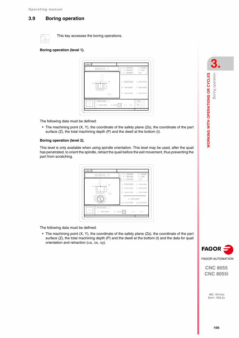
Operating manual
CNC 8055CNC 8055i
WO
RK
ING
WIT
H O
PE
RA
TIO
NS
OR
CY
CL
ES
3.
·MC· OPTIONSOFT: V02.2X
·105·
Bor
ing
oper
atio
n
3.9 Boring operation
Boring operation (level 1).
The following data must be defined:
• The machining point (X, Y), the coordinate of the safety plane (Zs), the coordinate of the partsurface (Z), the total machining depth (P) and the dwell at the bottom (t).
Boring operation (level 2).
This level is only available when using spindle orientation. This level may be used, after the quailhas penetrated, to orient the spindle, retract the quail before the exit movement, thus preventing thepart from scratching.
The following data must be defined:
• The machining point (X, Y), the coordinate of the safety plane (Zs), the coordinate of the partsurface (Z), the total machining depth (P) and the dwell at the bottom (t) and the data for quailorientation and retraction (s, x, y).
This key accesses the boring operations.

·106·
Operating manual
CNC 8055CNC 8055i
3.
WO
RK
ING
WIT
H O
PE
RA
TIO
NS
OR
CY
CL
ES
·MC· OPTIONSOFT: V02.2X
Bor
ing
oper
atio
n
3.9.1 Definition of data
Coordinates of the machining point.
The coordinates are defined one by one. After placing the cursor on the coordinates of the axes tobe defined, the value is entered in one of the following ways.
• Entering the value manually. Key in the desired value and press [ENTER].
• Assign the current machine position.
Jog the axis with the handwheel or the JOG keys up to the desired point. Press [RECALL] sothe selected data assumes the value shown in the top right window and press [ENTER].
The top right window shows the tool position at all times.
Machining conditions in Z (Zs, Z, P, I, t).
The machining conditions are defined one by one.
• The Zs and Z values are defined as the coordinates of the machining point.
• To define the rest of the values (P, t), go to the corresponding window, key in the desired valueand press [ENTER].
Exit type at level 1.
The exit movement may be done in two ways:
Data for quail orientation and retraction (s, Dx, Dy).
These data are defined one by one. Place the cursor in the corresponding window, key in the desiredvalue and press [ENTER].
It first orients the quail, it then moves back in XY and finally goes up in rapid (G00) with the spindlestopped.
To select the type of exit, place the cursor over this icon and press the two-color key.
At machining feedrate (G01) and with the spindle turning.
In rapid (G00) and with the spindle stopped.

Operating manual
CNC 8055CNC 8055i
WO
RK
ING
WIT
H O
PE
RA
TIO
NS
OR
CY
CL
ES
3.
·MC· OPTIONSOFT: V02.2X
·107·
Rea
min
g op
erat
ion
3.10 Reaming operation
Reaming operation.
The following data must be defined:
• The machining point (X, Y), the coordinate of the safety plane (Zs), the coordinate of the partsurface (Z), the total machining depth (P) and the dwell at the bottom (t).
This key accesses the reaming operation.

·108·
Operating manual
CNC 8055CNC 8055i
3.
WO
RK
ING
WIT
H O
PE
RA
TIO
NS
OR
CY
CL
ES
·MC· OPTIONSOFT: V02.2X
Rea
min
g op
erat
ion
3.10.1 Definition of data
Coordinates of the machining point.
The coordinates are defined one by one. After placing the cursor on the coordinates of the axes tobe defined, the value is entered in one of the following ways.
• Entering the value manually. Key in the desired value and press [ENTER].
• Assign the current machine position.
Jog the axis with the handwheel or the JOG keys up to the desired point. Press [RECALL] sothe selected data assumes the value shown in the top right window and press [ENTER].
The top right window shows the tool position at all times.
Machining conditions in Z (Zs, Z, P, I, t).
The machining conditions are defined one by one.
• The Zs and Z values are defined as the coordinates of the machining point.
• To define the rest of the values (P, t), go to the corresponding window, key in the desired valueand press [ENTER].
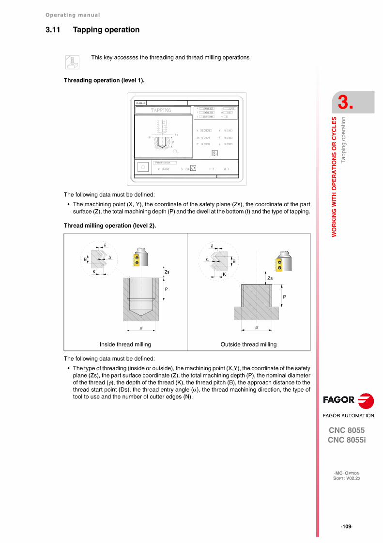
Operating manual
CNC 8055CNC 8055i
WO
RK
ING
WIT
H O
PE
RA
TIO
NS
OR
CY
CL
ES
3.
·MC· OPTIONSOFT: V02.2X
·109·
Tap
ping
ope
ratio
n
3.11 Tapping operation
Threading operation (level 1).
The following data must be defined:
• The machining point (X, Y), the coordinate of the safety plane (Zs), the coordinate of the partsurface (Z), the total machining depth (P) and the dwell at the bottom (t) and the type of tapping.
Thread milling operation (level 2).
The following data must be defined:
• The type of threading (inside or outside), the machining point (X,Y), the coordinate of the safetyplane (Zs), the part surface coordinate (Z), the total machining depth (P), the nominal diameterof the thread (), the depth of the thread (K), the thread pitch (B), the approach distance to thethread start point (Ds), the thread entry angle (), the thread machining direction, the type oftool to use and the number of cutter edges (N).
This key accesses the threading and thread milling operations.
Inside thread milling Outside thread milling
Zs
P
B
K
Zs
P
B
K

·110·
Operating manual
CNC 8055CNC 8055i
3.
WO
RK
ING
WIT
H O
PE
RA
TIO
NS
OR
CY
CL
ES
·MC· OPTIONSOFT: V02.2X
Tap
ping
ope
ratio
n
3.11.1 Definition of data (threading)
Coordinates of the machining point.
The coordinates are defined one by one. After placing the cursor on the coordinates of the axes tobe defined, the value is entered in one of the following ways.
• Entering the value manually. Key in the desired value and press [ENTER].
• Assign the current machine position.
Jog the axis with the handwheel or the JOG keys up to the desired point. Press [RECALL] sothe selected data assumes the value shown in the top right window and press [ENTER].
The top right window shows the tool position at all times.
Machining conditions in Z (Zs, Z, P, I, t).
The machining conditions are defined one by one.
• The Zs and Z values are defined as the coordinates of the machining point.
• To define the rest of the values (P, t), go to the corresponding window, key in the desired valueand press [ENTER].
Type of tapping.
Selecting rigid tapping with relief displays two fields for defining the penetration step and thewithdrawal distance.
I Penetration step
B Withdrawal distance
Thread definition.
The cycle offers two ways to define the thread:
• Defining the pitch (p) the spindle speed (S).
• Defining the feedrate (F) the spindle speed (S).
To select one of the ways, the "Penetration" area shows an icon with 2 states [p, S] and [F, S]. Toselect the desired one, select the icon and press the two-color key, the cycle will show the selectedfields.
Rigid tapping. Without a clutch.
Rigid tapping with relief.
Non-rigid tapping. With a clutch.

Operating manual
CNC 8055CNC 8055i
WO
RK
ING
WIT
H O
PE
RA
TIO
NS
OR
CY
CL
ES
3.
·MC· OPTIONSOFT: V02.2X
·111·
Tap
ping
ope
ratio
n
TOOL WITHDRAWAL
While machining, the CNC lets withdraw the tool to the starting plane stopping the spindle whenthe tool reaches the starting plane.
Activating PLC mark RETRACYC (M5065) stops the main axis and the spindle, the tool is withdrawnchanging the direction of the axis and spindle while keeping the machining F and S values.
The stopping and starting sequence of the spindle and the axis when tapping keeps the samesynchronism and dwells as during the execution of the canned cycle.
Options after tool withdrawal
Once the tool has been retracted, the user will have the following options:
• Finish the hole.
• Go to the next hole.
• Go into tool inspection.
After this, the CNC will display the following message:
"To end the cycle, press START to skip to the next SKIPCYCL".
Finish the hole:
To finish the hole, press the [START] key.
The hole is repeated from the starting plane under the same F and S conditions without stoppingat the point where it stopped.
Go to the next hole:
To go to the next hole, activate the PLC mark SKIPCYCL.
The CNC will display the following message:
"Press [START] to continue".
Pressing the [START] key, the CNC considers the cycle to be finished and continues with the nextblock.
Go into tool inspection
If you don't wish to finish the hole nor go to the next hole, it is possible to go into a standard toolinspection.
In this case, a block must be selected and a standard repositioning must be done before resumingthe execution of the program.
After inspecting the tool, once repositioning is done, the following choices will be offered:
• Resume the interrupted cycle.
• Skip the interrupted cycle and resume at the next block.

·112·
Operating manual
CNC 8055CNC 8055i
3.
WO
RK
ING
WIT
H O
PE
RA
TIO
NS
OR
CY
CL
ES
·MC· OPTIONSOFT: V02.2X
Tap
ping
ope
ratio
n
3.11.2 Definition of data (thread milling)
Coordinates of the machining point.
The coordinates are defined one by one. After placing the cursor on the coordinates of the axes tobe defined, the value is entered in one of the following ways.
• Entering the value manually. Key in the desired value and press [ENTER].
• Assign the current machine position.
Jog the axis with the handwheel or the JOG keys up to the desired point. Press [RECALL] sothe selected data assumes the value shown in the top right window and press [ENTER].
The top right window shows the tool position at all times.
Type of threading
[ Zs ] Safety coordinate
Defines the safety plane coordinate along the Z axis.
[ Z ] Part surface
Defines the Z coordinate of the part surface.
[ P ] Machining depth
Defines the total milling depth. If programmed with a 0 value, the CNC will display the correspondingerror message.
[ ] Thread diameter
Defines the nominal diameter of the thread If not programmed or programmed with a 0 value, theCNC will display the corresponding error message.
[ K ] Thread depth
It defines the distance between the crest and the root of the thread. If not programmed, the CNCissues the corresponding error.
[ B ] Thread pitch
Defines the thread pitch. If not programmed or programmed with a 0 value, the CNC will display thecorresponding error message.
[ Ds ] Approach distance
Approach distance to the thread entry. If not programmed or programmed with a 0 value, it will enterthe thread from the center of the hole.
Thread entry (start) angle
Angle (in degrees) of the segment formed by the center of the hole and the thread entry point withrespect to the abscissa axis. If not programmed, a value of 0 is assumed.
Defines the type of threading to be carried out (inside or outside).

Operating manual
CNC 8055CNC 8055i
WO
RK
ING
WIT
H O
PE
RA
TIO
NS
OR
CY
CL
ES
3.
·MC· OPTIONSOFT: V02.2X
·113·
Tap
ping
ope
ratio
n
Thread cutting direction
Thread cutting direction
Tool type
[ N ] Number of cutting edges of the cutter.
It defines the number of cutting edges of the cutter (only when machining with a cutter of n edges).If not programmed or programmed with a 0 value, the CNC will display the corresponding errormessage.
It defines the thread cutting direction.
It defines the thread cutting direction (from the part surface down to the bottomof the thread or from the bottom up to the part surface).
It defines the type of tool used for machining.
• Single-pitch thread.
• Thread cutting one thread per each pass (Single-edge cutter).
• Thread cutting n threads per each pass (n-edge cutter).

·114·
Operating manual
CNC 8055CNC 8055i
3.
WO
RK
ING
WIT
H O
PE
RA
TIO
NS
OR
CY
CL
ES
·MC· OPTIONSOFT: V02.2X
Dril
ling
and
cent
er p
unch
ing
oper
atio
ns
3.12 Drilling and center punching operations
Center punching operation.
The following data must be defined:
• The machining point (X, Y), the coordinate of the safety plane (Zs), the coordinate of the partsurface (Z), the dwell at the bottom (t) and the type of center punching.
Drilling operation (level 1).
The following data must be defined:
• The machining point (X, Y), the coordinate of the safety plane (Zs), the coordinate of the partsurface (Z), the total machining depth (P), the drilling peck (I) and the dwell at the bottom (t).
Drilling operation (level 2).
It may be used to set the withdrawal distance (B) after each penetration.
This key accesses the drilling, center punching and bore milling operations.

Operating manual
CNC 8055CNC 8055i
WO
RK
ING
WIT
H O
PE
RA
TIO
NS
OR
CY
CL
ES
3.
·MC· OPTIONSOFT: V02.2X
·115·
Dril
ling
and
cent
er p
unch
ing
oper
atio
ns
The following data must be defined:
• The machining point (X, Y), the coordinate of the safety plane (Zs), the coordinate of the partsurface (Z), the total machining depth (P), the drilling peck (I) and the dwell at the bottom (t) andthe withdrawal distance after each penetration (B).
Drilling operation (level 3).
It may be used to set the withdrawal coordinate (Zr) after each penetration.
The following data must be defined:
• The machining point (X, Y), the coordinate of the safety plane (Zs), the coordinate of the partsurface (Z), the withdrawal coordinate (Zr), the total machining depth (P), the drilling peck (I) andthe dwell at the bottom (t).
Bore milling operation (level 5).
This cycle may be used to increase the diameter of a hole through a helical movement of the tool.Besides this, if the tool allows it, it is also possible to mill a hole without having to drill it first.
The following data must be defined:
• The machining point (X, Y), the coordinate of the safety plane (Zs), the coordinate of the partsurface (Z), the hole diameter , the diameter of the pre-drilled hole K, the total machiningdepth (P), the helical penetration pitch (B), the direction of the helical drilling path and the millingat the bottom.
P
Zs
k

·116·
Operating manual
CNC 8055CNC 8055i
3.
WO
RK
ING
WIT
H O
PE
RA
TIO
NS
OR
CY
CL
ES
·MC· OPTIONSOFT: V02.2X
Dril
ling
and
cent
er p
unch
ing
oper
atio
ns
3.12.1 Definition of data
Coordinates of the machining point.
The coordinates are defined one by one. After placing the cursor on the coordinates of the axes tobe defined, the value is entered in one of the following ways.
• Entering the value manually. Key in the desired value and press [ENTER].
• Assign the current machine position.
Jog the axis with the handwheel or the JOG keys up to the desired point. Press [RECALL] sothe selected data assumes the value shown in the top right window and press [ENTER].
The top right window shows the tool position at all times.
Machining conditions in Z (Zs, Z, Zr, P, I, t, B).
The machining conditions are defined one by one.
• The Zs and Z values are defined as the coordinates of the machining point.
• To define the rest of the values (Zr, P, I, t, B), go to the corresponding window, key in the desiredvalue and press [ENTER].
Type of center punching.
• Defining the total machining depth (P).
• Defining the angle of the punch () and the diameter of the point ().
To define the values (P, , ), go to the corresponding window, key in the desired value and press[ENTER].
Hole diameter (
Defines the diameter of the hole. To set this value, place the cursor in the corresponding window,key in the desired value and press [ENTER].
If not programmed or programmed with a 0 value, the CNC will display the corresponding errormessage.
Diameter of the pre-drilled hole (K).
Starting with a hole previously drilled, this parameter defines the diameter of that hole. If notprogrammed or programmed with a 0 value, it means that no hole has been previously drilled.
The tool must meet the following conditions:
• The tool radius must be smaller than J/2.
• The tool radius must be equal to or larger than (J-K)/4.
If these two conditions are not met, the CNC issues the corresponding error.
Helical penetration step (B).
It defines the helical penetration step (only for bore milling). To set this value, place the cursor inthe corresponding window, key in the desired value and press [ENTER].
If not programmed or programmed with a 0 value, the CNC will display the corresponding errormessage.
Drilling direction.
Bottom milling.
To select the type of tapping, place the cursor over this icon and press the two-color key.The type of center punching may be defined in two ways.
Defines the direction of the helical drilling path.
It defines whether the bottom of the hole (blind hole) is milled or not (through hole).

Operating manual
CNC 8055CNC 8055i
WO
RK
ING
WIT
H O
PE
RA
TIO
NS
OR
CY
CL
ES
3.
·MC· OPTIONSOFT: V02.2X
·117·
Dril
ling
and
cent
er p
unch
ing
oper
atio
ns
3.12.2 Tool withdrawal
While drilling a hole, the CNC lets withdraw the tool to the starting plane stopping the spindle whenthe tool reaches the starting plane.
Activating PLC mark RETRACYC (M5065) stops the main axis and the tool is withdrawn withoutstopping the spindle. The spindle stops when the tool is retracted, once it reaches the starting plane.
Options after tool withdrawal
Once the tool has been retracted, the user will have the following options:
• Finish the hole.
• Go to the next hole.
• Go into tool inspection.
After this, the CNC will display the following message:
"To end the cycle, press START to skip to the next SKIPCYCL".
Finish the hole:
To finish the hole, press the [START] key.
It goes down in G0 with spindle running to 1 mm before the coordinate where the hole stopped. Fromthen on, it continues at the F and S programmed in the cycle.
Go to the next hole:
To go to the next hole, activate the PLC mark SKIPCYCL.
The CNC will display the following message:
"Press [START] to continue".
Pressing the [START] key, the CNC considers the cycle to be finished and continues with the nextblock.
Go into tool inspection
If you don't wish to finish the hole nor go to the next hole, it is possible to go into a standard toolinspection.
In this case, a block must be selected and a standard repositioning must be done before resumingthe execution of the program.
After inspecting the tool, once repositioning is done, the following choices will be offered:
• Resume the interrupted cycle.
• Skip the interrupted cycle and resume at the next block.

·118·
Operating manual
CNC 8055CNC 8055i
3.
WO
RK
ING
WIT
H O
PE
RA
TIO
NS
OR
CY
CL
ES
·MC· OPTIONSOFT: V02.2X
Mul
tiple
pos
ition
ing
3.13 Multiple positioning
Some cycles may be carried out in the tool position or may be associated a multiple positioning sothe cycle may be repeated in several locations. Multiple positioning may be associated with thefollowing cycles.
• Boring, reaming, tapping, drilling and center punching operations.
• 2D and 3D pockets.
• Bosses.
Use the following keys to select multiple positioning. The positioning moves may be selected witheach one of the following keys:
When using one of these keys, the CNC selects the corresponding positioning and changes thedisplay on the screen. The CNC keeps the lamp for the selected operation (pocket, boss, boring,reaming, etc.) on and the bottom of the screen shows the data for that operation.
Associating a multiple positioning with a cycle
A multiple positioning may be associated with a cycle as follows:
1. Definition of the machining cycle, including the position of the starting point.
2. Selection of the type of positioning to be associated with.
3. Programming of the different points of the positioning.
The cycle assumes as first positioning point the starting point of the machining operation. Thispoint may be modified when defining the positioning.
In 2D and 3D pockets, the reference points for the positioning must be the starting point of theoutside profile.
To de-select a cycle and return to the standard screen, press the key for the selected cycle (the onewith the lamp on) or the [ESC] key.
Multiple positioning in pockets and bosses
The screens of the pockets and bosses will indicate with icons which positioning they haveassociated or whether they are alone.
In the positioning, an icon will show the pocket or boss to be repeated and the bottom screen willgive information on its geometry (except in profile pockets). The starting position of rectangularpockets and bosses may be changed; the positioning movements will be different depending onwhether the starting point is at the vertex or in the center.
Multiple positioning in several locations.
Multiple positioning in a straight line.
Multiple positioning in an arc.
Multiple positioning in a rectangular pattern.
Multiple positioning in a grid pattern.

Operating manual
CNC 8055CNC 8055i
WO
RK
ING
WIT
H O
PE
RA
TIO
NS
OR
CY
CL
ES
3.
·MC· OPTIONSOFT: V02.2X
·119·
Mul
tiple
pos
ition
ing
When machining pockets and bosses at the different positions, proceed as follows:
• There is neither roughing or finishing operation.
The machining takes place point to point; the whole cycle is executed at each point (there is notool change).
• There is a roughing and finishing operation with the same tool and it is not possible to program"M" functions between them.
The machining takes place point to point; the whole cycle is executed at each point (there is notool change).
• There is a roughing and finishing operation with a different tool or it is possible to program "M"functions between them.
It first does the roughing and then all the finishing operations (only one tool change).
Rectangular pocket in different multiple positionings.
The availability of "M" functions in the cycles is determined with g.m.p. "CODISET (P147)".i

·120·
Operating manual
CNC 8055CNC 8055i
3.
WO
RK
ING
WIT
H O
PE
RA
TIO
NS
OR
CY
CL
ES
·MC· OPTIONSOFT: V02.2X
Mul
tiple
pos
ition
ing
3.13.1 Multiple positioning in several locations
Up to 12 points (X1, Y1) ··· (X12, Y12) may be defined. When not using the 12 definition points, thefirst unused point must be defined with the same coordinates as the last point.
Data definition.
The coordinates are defined one by one. After placing the cursor on the coordinates of the axes tobe defined, the value is entered in one of the following ways.
• Entering the value manually. Key in the desired value and press [ENTER].
• Assign the current machine position.
Jog the axis with the handwheel or the JOG keys up to the desired point. Press [RECALL] sothe selected data assumes the value shown in the top right window and press [ENTER].
The top right window shows the tool position at all times.
If a coordinate is left blank, the cycle will assume that it is the same as that of the previous one.
The coordinates of each point may also be defined incrementally. To do that, select the desiredcoordinate with the cursor and press the two-color key. Both coordinates of the selected point willbe shown preceded by the "" icon that indicates the incremental value with respect to the previouspoint.
This key associates this positioning with the active operation.
If defined... The CNC assumes...
X1 25.323 Y1 26.557 Point: X1 25.323 Y1 26.557
X2 Y2 78.998 Point: X2 25.323 Y2 78.998
X3 67.441 Y3 83.231 Point: X3 67.441 Y3 83.231
X4 Y4 Point: X4 67.441 Y4 83.231
X5 Y5 There are no more points, it is a repetition of the previous point.

Operating manual
CNC 8055CNC 8055i
WO
RK
ING
WIT
H O
PE
RA
TIO
NS
OR
CY
CL
ES
3.
·MC· OPTIONSOFT: V02.2X
·121·
Mul
tiple
pos
ition
ing
3.13.2 Multiple positioning in a straight line
Data definition.
The coordinates are defined one by one. After placing the cursor on the coordinates of the axes tobe defined, the value is entered in one of the following ways.
• Entering the value manually. Key in the desired value and press [ENTER].
• Assign the current machine position.
Jog the axis with the handwheel or the JOG keys up to the desired point. Press [RECALL] sothe selected data assumes the value shown in the top right window and press [ENTER].
The top right window shows the tool position at all times.
To define the rest of the values (I, N, , L), go to the corresponding window, key in the desired valueand press [ENTER].
This key associates this positioning with the active operation.
The positioning may be defined in 5 ways. To select the desired type, place the cursorover the icon and press the two-color key. The icon shows the selected option and thetotal number of options available.
1) Coordinates of the starting point. (X1, Y1)
Coordinates of the last point. (Xn, Yn)
Distance between machining operations. (I)
2) Coordinates of the starting point. (X1, Y1)
Coordinates of the last point. (Xn, Yn)
Number of points to machine. (N)
3) Coordinates of the starting point. (X1, Y1)
Inclination angle. ()
Distance to travel. (L)
Distance between machining operations. (I)
4) Coordinates of the starting point. (X1, Y1)
Inclination angle. ()
Distance to travel. (L)
Number of points to machine. (N)
5) Coordinates of the starting point. (X1, Y1)
Inclination angle. ()
Number of points to machine. (N)
Distance between machining operations. (I)

·122·
Operating manual
CNC 8055CNC 8055i
3.
WO
RK
ING
WIT
H O
PE
RA
TIO
NS
OR
CY
CL
ES
·MC· OPTIONSOFT: V02.2X
Mul
tiple
pos
ition
ing
3.13.3 Multiple positioning in an arc
Multiple positioning in an arc (level 1).
This key associates this positioning with the active operation.
The positioning may be defined in 6 ways. To select the desired type, place the cursorover the icon and press the two-color key. The icon shows the selected option and thetotal number of options available.
1) Coordinates of the starting point (X1, Y1)
Center coordinates (Xc, Yc)
Angle of the last point ()
Angular distance between machining operations ()
2) Coordinates of the starting point (X1, Y1)
Radius (R)
Angle of the starting point ()
Angle of the last point ()
Angular distance between machining operations ()
3) Coordinates of the starting point (X1, Y1)
Center coordinates (Xc, Yc)
Number of points to machine (N)
Angle of the last point ()
4) Coordinates of the starting point (X1, Y1)
Center coordinates (Xc, Yc)
Number of points to machine (N)
Angular distance between machining operations ()
5) Coordinates of the starting point (X1, Y1)
Radius (R)
Angle of the starting point ()
Number of points to machine (N)
Angle of the last point ()
6) Coordinates of the starting point (X1, Y1)
Radius (R)
Angle of the starting point ()
Number of points to machine (N)
Angular distance between machining operations ()

Operating manual
CNC 8055CNC 8055i
WO
RK
ING
WIT
H O
PE
RA
TIO
NS
OR
CY
CL
ES
3.
·MC· OPTIONSOFT: V02.2X
·123·
Mul
tiple
pos
ition
ing
Multiple positioning in an arc (level 2).
The following data must be defined:
• Center coordinates (Xc, Yc).
• The starting point in Polar coordinates; Radius (R) and angle ().
2 of the following data must be defined. When defining all 3 of them (if they are other than 0), thecycle assumes the (N) and () values.
(N) Number of points to machine.
() Angular distance between machining operations.
() Angle of the last point.
Data definition.
The coordinates are defined one by one. After placing the cursor on the coordinates of the axes tobe defined, the value is entered in one of the following ways.
• Entering the value manually. Key in the desired value and press [ENTER].
• Assign the current machine position.
Jog the axis with the handwheel or the JOG keys up to the desired point. Press [RECALL] sothe selected data assumes the value shown in the top right window and press [ENTER].
The top right window shows the tool position at all times.
To define the rest of the values (R, N, , , ), go to the corresponding window, key in the desiredvalue and press [ENTER].

·124·
Operating manual
CNC 8055CNC 8055i
3.
WO
RK
ING
WIT
H O
PE
RA
TIO
NS
OR
CY
CL
ES
·MC· OPTIONSOFT: V02.2X
Mul
tiple
pos
ition
ing
3.13.4 Multiple positioning in a rectangular pattern
Data definition.
The coordinates are defined one by one. After placing the cursor on the coordinates of the axes tobe defined, the value is entered in one of the following ways.
• Entering the value manually. Key in the desired value and press [ENTER].
• Assign the current machine position.
Jog the axis with the handwheel or the JOG keys up to the desired point. Press [RECALL] sothe selected data assumes the value shown in the top right window and press [ENTER].
The top right window shows the tool position at all times.
To define the rest of the values (Lx, Ly, Ix, Iy, , , Nx, Ny), go to the corresponding window, keyin the desired value and press [ENTER].
This key associates this positioning with the active operation.
The positioning may be defined in 3 ways. To select the desired type, place the cursorover the icon and press the two-color key. The icon shows the selected option and thetotal number of options available.
1) Coordinates of the starting point (X1, Y1)X and Y lengths (Lx, Ly)
X and Y distances between machining operations. (Ix, Iy)
Rotation angle ()Angle between paths ()
2) Coordinates of the starting point (X1, Y1)
X and Y lengths (Lx, Ly)Number of machining operations on X and Y (Nx, Ny)
Rotation angle ()
Angle between paths ()
3) Coordinates of the starting point (X1, Y1)
X and Y distances between machining operations. (Ix, Iy)
Number of machining operations on X and Y (Nx, Ny)Rotation angle ()
Angle between paths ()
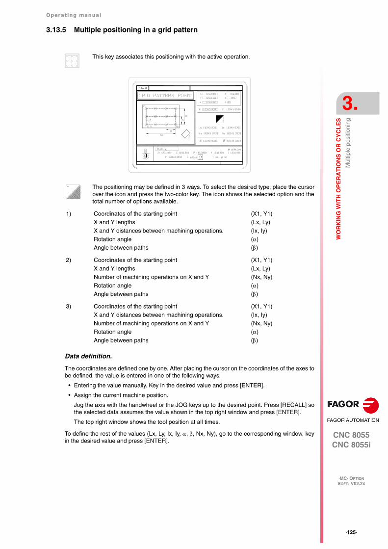
Operating manual
CNC 8055CNC 8055i
WO
RK
ING
WIT
H O
PE
RA
TIO
NS
OR
CY
CL
ES
3.
·MC· OPTIONSOFT: V02.2X
·125·
Mul
tiple
pos
ition
ing
3.13.5 Multiple positioning in a grid pattern
Data definition.
The coordinates are defined one by one. After placing the cursor on the coordinates of the axes tobe defined, the value is entered in one of the following ways.
• Entering the value manually. Key in the desired value and press [ENTER].
• Assign the current machine position.
Jog the axis with the handwheel or the JOG keys up to the desired point. Press [RECALL] sothe selected data assumes the value shown in the top right window and press [ENTER].
The top right window shows the tool position at all times.
To define the rest of the values (Lx, Ly, Ix, Iy, , , Nx, Ny), go to the corresponding window, keyin the desired value and press [ENTER].
This key associates this positioning with the active operation.
The positioning may be defined in 3 ways. To select the desired type, place the cursorover the icon and press the two-color key. The icon shows the selected option and thetotal number of options available.
1) Coordinates of the starting point (X1, Y1)X and Y lengths (Lx, Ly)
X and Y distances between machining operations. (Ix, Iy)
Rotation angle ()Angle between paths ()
2) Coordinates of the starting point (X1, Y1)
X and Y lengths (Lx, Ly)Number of machining operations on X and Y (Nx, Ny)
Rotation angle ()
Angle between paths ()
3) Coordinates of the starting point (X1, Y1)
X and Y distances between machining operations. (Ix, Iy)
Number of machining operations on X and Y (Nx, Ny)Rotation angle ()
Angle between paths ()

·126·
Operating manual
CNC 8055CNC 8055i
3.
WO
RK
ING
WIT
H O
PE
RA
TIO
NS
OR
CY
CL
ES
·MC· OPTIONSOFT: V02.2X
Mul
tiple
pos
ition
ing

CNC 8055CNC 8055i
·MC· OPTIONSOFT: V02.2X
4
·127·
OPERATING IN ISO MODE
The ISO mode is accessed with the [ISO] key.
• When operating with operations or cycles, press the [ISO] key once.
• When operating in jog mode, press the [ISO] key twice; the first time to access the MDI modeand the second time to access the ISO mode. See "2.10 ISO management" on page 69.
Cycle levels
The ISO mode offers several editing levels. Each level has its own screen and the main window ofthe cycle indicates, with tabs, the available levels and which one is selected.
Simulating, executing or saving ISO cycles
Once the cycle data or the blocks have been edited, press [ESC]. The upper right side of the screenwill show the "start" symbol. From this moment one, the edited blocks may be simulated, executedor saved like any operation or cycle.
• To simulate the blocks, press the [GRAPHICS] key.
• To execute the blocks, press the [START] key.
• To save the edited blocks, press the [P.PROG] key.
It is possible to combine ISO-coded blocks with standard and/or user machining cycles to createpart-programs. See chapter "5 Saving programs".
To change levels, use the [LEVEL CYCLE] key or the [page up] and [page down] keysto scroll up and down through the various levels.
Block editing Work zones
Zero offsets and presets Mirror image
Insert labels and repetitionsfrom label to label
Coordinate rotation
Scaling factor Plane change

·128·
Operating manual
CNC 8055CNC 8055i
4.
OP
ER
AT
ING
IN IS
O M
OD
E
·MC· OPTIONSOFT: V02.2X
Edi
ting
bloc
ks in
ISO
mod
e
4.1 Editing blocks in ISO mode
When accessing the ISO mode, the CNC displays a special screen for editing up to 6 program blockseither in ISO code or in high level language. After editing a block, press [ENTER] to validate it.
Once the block or blocks have been edited, press [ESC]. The upper right side of the screen will showthe "start" symbol. From this moment one, the edited blocks may be simulated, executed or savedlike any operation or cycle.
G95 G96 S120 M3
G0 Z100
G1 X30 F0.1
Example:
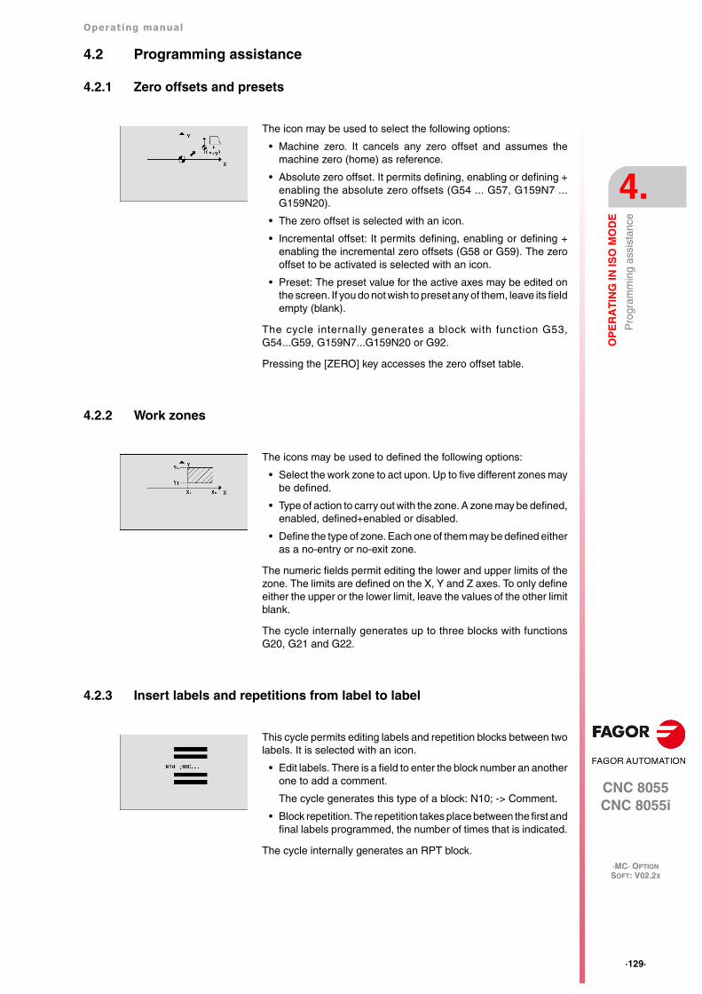
Operating manual
CNC 8055CNC 8055i
OP
ER
AT
ING
IN IS
O M
OD
E
4.
·MC· OPTIONSOFT: V02.2X
·129·
Pro
gram
min
g as
sist
ance
4.2 Programming assistance
4.2.1 Zero offsets and presets
4.2.2 Work zones
4.2.3 Insert labels and repetitions from label to label
The icon may be used to select the following options:
• Machine zero. It cancels any zero offset and assumes themachine zero (home) as reference.
• Absolute zero offset. It permits defining, enabling or defining +enabling the absolute zero offsets (G54 ... G57, G159N7 ...G159N20).
• The zero offset is selected with an icon.
• Incremental offset: It permits defining, enabling or defining +enabling the incremental zero offsets (G58 or G59). The zerooffset to be activated is selected with an icon.
• Preset: The preset value for the active axes may be edited onthe screen. If you do not wish to preset any of them, leave its fieldempty (blank).
The cycle internally generates a block with function G53,G54...G59, G159N7...G159N20 or G92.
Pressing the [ZERO] key accesses the zero offset table.
The icons may be used to defined the following options:
• Select the work zone to act upon. Up to five different zones maybe defined.
• Type of action to carry out with the zone. A zone may be defined,enabled, defined+enabled or disabled.
• Define the type of zone. Each one of them may be defined eitheras a no-entry or no-exit zone.
The numeric fields permit editing the lower and upper limits of thezone. The limits are defined on the X, Y and Z axes. To only defineeither the upper or the lower limit, leave the values of the other limitblank.
The cycle internally generates up to three blocks with functionsG20, G21 and G22.
This cycle permits editing labels and repetition blocks between twolabels. It is selected with an icon.
• Edit labels. There is a field to enter the block number an anotherone to add a comment.
The cycle generates this type of a block: N10; -> Comment.
• Block repetition. The repetition takes place between the first andfinal labels programmed, the number of times that is indicated.
The cycle internally generates an RPT block.

·130·
Operating manual
CNC 8055CNC 8055i
4.
OP
ER
AT
ING
IN IS
O M
OD
E
·MC· OPTIONSOFT: V02.2X
Pro
gram
min
g as
sist
ance
4.2.4 Mirror image
4.2.5 Scaling factor
4.2.6 Coordinate rotation
The icons may be used to select the following options:
• Select the action to be carried out. It is possible to cancel theactive mirror image, define a new one canceling the previousones or define a new one and add it to the one that is currentlyactive.
• Select the axes on which mirror image is applied. For a newmirror image, you may select between the X, Y or X-Y axes. Foran additive mirror image, you may select between the X and Yaxes. This icon is not shown when selecting mirror imagecancellation.
The cycle internally generates an ISO block that contains acombination of functions G10, G11 and G12.
An icon is used to indicate whether to cancel the existing scalingfactor or activate a new one. In the latter case, a numeric field isdisplayed to define the value of the scaling factor.
The cycle internally generates a block with function G72.
An icon is used to select the action to be carried out. It is possibleto cancel the active coordinate rotation, define a new one cancelingthe previous one or define a new one adding it to the one currentlyactive.
To define or activate a coordinate rotation, it shows three numericfields to edit the angle and the center of rotation.
The cycle internally generates two blocks with function G73.

Operating manual
CNC 8055CNC 8055i
OP
ER
AT
ING
IN IS
O M
OD
E
4.
·MC· OPTIONSOFT: V02.2X
·131·
Pro
gram
min
g as
sist
ance
4.2.7 Plane change
An icon may be used to select the plane (G16, G17, G18 or G19)where the canned cycle will be executed. This way, the cycles maybe executed in any of the three planes.
When selecting G17, G18 or G19, the three boxes are automaticallyfilled in with the names of the corresponding axes. Also, the mainview highlights the selected plane.
When selecting G16, the user can write the names of the axes inthe boxes as he wishes. In this case, the main drawing does nothighlight any plane.
If there are only XYZ axes, the selection icon does not show theoption for free configuration (G16).
If a block is programmed with a change of plane; from then on, allthe milling cycles may be executed in the new plane.
When turning the CNC off and back on, it loses the plane it wasworking with and the work plane is the one indicated by machineparameter IPLANE (XY or ZX).
Icon that serves to indicate the plane active in the cycle when the selected plane doesnot correspond with the plane indicated by general machine parameter IPLANE(P11). This icon will only be shown before pressing [START], after pressing [ESC].

·132·
Operating manual
CNC 8055CNC 8055i
4.
OP
ER
AT
ING
IN IS
O M
OD
E
·MC· OPTIONSOFT: V02.2X
Pro
gram
min
g as
sist
ance

CNC 8055CNC 8055i
·MC· OPTIONSOFT: V02.2X
5
·133·
SAVING PROGRAMS
Part-programs may be edited, simulated and executed.
Each one of these programs is made up by concatenating simple operations or cycles and/or blocksedited in ISO code. Chapter "3 Working with operations or cycles" describes how to edit or definethose operations or cycles.
This chapter indicates how to operate with those part-programs through the following sections andsub-sections.
• List of saved programs.
• Seeing the contents of a program.
• Editing a new part-program.
• Saving an ISO block or a cycle.
• Deleting a new part program.
• Copying a part-program into another one.
• Modifying a part-program.
• Managing programs using the explorer

·134·
Operating manual
CNC 8055CNC 8055i
5.
SA
VIN
G P
RO
GR
AM
S
·MC· OPTIONSOFT: V02.2X
List
of s
aved
pro
gram
s
5.1 List of saved programs
The CNC will display the following information:
Press one of these keys to exit the directory or list of part-programs:
List of part-programs.
The left side shows the list of part-programs that are saved in the CNC's memory. Use the [][]keys to move the pointer over the list of programs. Use the [SHIFT][] y [SHIFT][] keys to scrolla page at a time.
It is possible to select the program by typing its number directly. If the desired program does not exist,the cursor will go to the nearest previous one. For example, to find program number 123, press thekeystroke sequence [1], [2] and [3]. The time interval between keystrokes must be shorter than 1.5seconds. A longer interval starts a new sequence.
Cycles that make up the part-program.
The right column shows the cycles and/or blocks edited in ISO code that make up the part. Oncethe list of programs has been selected, the following operations are possible:
• Creating a new part-program.
• Seeing the contents of a part-program.
• Deleting a new part program.
• Copying a part-program into another one.
• Modifying a part-program.
Press [P.PROG] to access the list of saved part-programs.
It is not possible to access the list of part-programs directly if the "Tool calibration" modeis selected. First, quit this mode; in other words, first press [ESC] and then [P.PROG].

Operating manual
CNC 8055CNC 8055i
SA
VIN
G P
RO
GR
AM
S
5.
·MC· OPTIONSOFT: V02.2X
·135·
See
the
cont
ents
of a
pro
gram
5.2 See the contents of a program
To see the contents of a part-program, select it on the left column using the pointer. To do that, usethe [][] keys. The right column shows the cycles that make up the part.
Once an operation has been selected, the following is possible:
• To see the operation in detail.
• To delete the operation.
• To move the operation to another position.
• To modify the operation.
When pressing [ENTER] or one of the [][] keys, the pointer switches to the rightcolumn. Now, the [][] keys may be used to move the pointer over the blocks or cyclesthat make up the part.
So, use the [][] keys to move up and down on each column and [][] keys to switch columns.i

·136·
Operating manual
CNC 8055CNC 8055i
5.
SA
VIN
G P
RO
GR
AM
S
·MC· OPTIONSOFT: V02.2X
See
the
cont
ents
of a
pro
gram
5.2.1 Seeing one of the operations in detail
In this moment it is possible to:
• Simulate the operation. See chapter "6 Execution and simulation".
• Execute the operation. See chapter "6 Execution and simulation".
• To modify the operation.
• Save the operation. Replacing the previous one or inserting it as a new one.
Once the desired operation has been selected using the pointer, press [RECALL]. TheCNC will show all the data for that operation.

Operating manual
CNC 8055CNC 8055i
SA
VIN
G P
RO
GR
AM
S
5.
·MC· OPTIONSOFT: V02.2X
·137·
Edi
t a n
ew p
art-
prog
ram
5.3 Edit a new part-program
To edit a new program, proceed as follows:
1. Press [P.PROG] to access the list of part-programs stored.
2. Select, with the pointer, the option "Creating new part" on the left column.
3. Press the [P.PROG] key. The bottom of the screen will request the number to beassigned to the new part-program and it will offer the first one available.
4. Enter the number of the desired program and press [ENTER].
It must be a number between 1 and 899999. Both included.
5. The CNC requests the comment to be associated with the part-program.
It is not necessary to associate a comment.
6. Press the [ENTER] or [ESC].
The CNC includes the new part-program in the list (left column).
From this moment on, all the desired operations may be saved in the desired order.

·138·
Operating manual
CNC 8055CNC 8055i
5.
SA
VIN
G P
RO
GR
AM
S
·MC· OPTIONSOFT: V02.2X
Sav
ing
an IS
O b
lock
or
a cy
cle
5.4 Saving an ISO block or a cycle
The block or cycle may be added at the end of the program, after the last operation or insert it between2 existing operations.
To save the block or cycle, proceed as follows:
1. Define the desired block or cycle assigning the relevant data to it.
2. Press [P.PROG] to access the list of part-programs stored.
3. Select, with the pointer, the desired program number on the left column and switch over to theright column.
4. Place the pointer on the operation after which the block or cycle is to be saved and press[ENTER].
Example:
To insert the "Drilling 1 + linear positioning" operation, once the operation has been defined, placethe pointer on the "Circular pocket" operation and press [ENTER].
To insert the "Profile 1" operation, once the operation has been defined, place the pointer on thelast operation "Threading + Grid pattern positioning" operation and press [ENTER].
Current program Desired program
Bidirectional surface milling in X Bidirectional surface milling in X
Rectangular pocket Rectangular pocket
Circular pocket Circular pocket
Drilling 1 + linear positioning
Drilling 1 + grid pattern positioning Drilling 1 + grid pattern positioning
Threading + Grid pattern positioning Threading + Grid pattern positioning
Profile 1

Operating manual
CNC 8055CNC 8055i
SA
VIN
G P
RO
GR
AM
S
5.
·MC· OPTIONSOFT: V02.2X
·139·
Del
ete
a ne
w p
art p
rogr
am
5.5 Delete a new part program
To delete a part-program, proceed as follows:
1. Press [P.PROG] to access the list of part-programs stored.
2. Select, with the pointer, the part-program to be deleted from the left column.
The bottom of the screen will show a message requesting confirmation of the deleting operation.
• If [ENTER] is pressed, the CNC will delete the selected program and will update the list of savedprograms.
• If [ESC] is pressed, the program will not be deleted and it will quit deleting operation.
3. Press [CLEAR].

·140·
Operating manual
CNC 8055CNC 8055i
5.
SA
VIN
G P
RO
GR
AM
S
·MC· OPTIONSOFT: V02.2X
Cop
ying
a p
art-
prog
ram
into
ano
ther
one
5.6 Copying a part-program into another one
To copy a part-program into another one, proceed as follows:
1. Press [P.PROG] to access the list of part-programs stored.
2. Select, with the pointer, the part-program to be copied from the left column.
3. Press the [P.PROG] key.
The bottom of the screen will show a message requesting the number to be assigned to the copy.
4. Enter the number of the desired program and press [ENTER].
It must be a number between 1 and 899999. Both included.
5. If there is already a part-program with that number, the bottom of the screen will show a messageasking to either replace it or cancel the operation?
If [ENTER] is pressed, the CNC will request a new program. If [ESC] is pressed, the CNC willnot delete the current program and will copy the program.
6. The CNC requests the comment to be associated with the new part-program (the copy).
It is not necessary to associate a comment.
7. Press the [ENTER] or [ESC]. The CNC updates the list of saved part-programs.

Operating manual
CNC 8055CNC 8055i
SA
VIN
G P
RO
GR
AM
S
5.
·MC· OPTIONSOFT: V02.2X
·141·
Mod
ify a
par
t-pr
ogra
m
5.7 Modify a part-program
To modify a part-program, proceed as follows:
1. Press [P.PROG] to access the list of part-programs stored.
2. Select, with the pointer, the part-program to be modified from the left column.
Once the program has been selected, the following operations are possible:
• To delete an operation.
• To move an operation to another position.
• To add or insert a new operation.
• To modify an existing operation.
·142·
Operating manual
CNC 8055CNC 8055i
5.
SA
VIN
G P
RO
GR
AM
S
·MC· OPTIONSOFT: V02.2X
Mod
ify a
par
t-pr
ogra
m
5.7.1 Delete an operation
To delete an operation, proceed as follows:
1. Select, with the pointer, the operation to be deleted from the right column.
2. Press [CLEAR].
The bottom of the screen will show a message requesting confirmation of the deleting operation.
• If [ENTER] is pressed, the CNC will delete the selected operation and will update the rightcolumn.
• If [ESC] is pressed, the operation will not be deleted and it will quit deleting operation.

Operating manual
CNC 8055CNC 8055i
SA
VIN
G P
RO
GR
AM
S
5.
·MC· OPTIONSOFT: V02.2X
·143·
Mod
ify a
par
t-pr
ogra
m
5.7.2 Add or insert a new operation
To add or insert an operation follow the same steps as for saving an operation.
1. Define the desired block or cycle assigning the relevant data to it.
2. Press [P.PROG] to access the list of part-programs stored.
3. Place the pointer on the operation after which the block or cycle is to be saved and press[ENTER].

·144·
Operating manual
CNC 8055CNC 8055i
5.
SA
VIN
G P
RO
GR
AM
S
·MC· OPTIONSOFT: V02.2X
Mod
ify a
par
t-pr
ogra
m
5.7.3 Move an operation to another position
To move an operation to another position, proceed as follows:
1. Select, with the pointer, the operation to be moved from the right column.
Example:
Select the "Rectangular pocket" operation and press the two-color key. Then position the cursor onthe "Threading + Grid pattern positioning" operation and press [ENTER].
2. Press the two-color key.
The CNC will highlight that operation.
3. Place the cursor on the operation after which the operation is to be placed and press[ENTER].
Current program Desired program
Bidirectional surface milling in X Bidirectional surface milling in X
Rectangular pocket Circular pocket
Circular pocket Drilling 1 + linear positioning
Drilling 1 + linear positioning Drilling 1 + grid pattern positioning
Drilling 1 + grid pattern positioning Threading + Grid pattern positioning
Threading + Grid pattern positioning Rectangular pocket
Profile 1 Profile 1

Operating manual
CNC 8055CNC 8055i
SA
VIN
G P
RO
GR
AM
S
5.
·MC· OPTIONSOFT: V02.2X
·145·
Mod
ify a
par
t-pr
ogra
m
5.7.4 Modify an existing operation
To modify an operation, proceed as follows:
1. Select, with the pointer, the block or cycle to be modified from the right column.
2. Press the [RECALL] key.
The CNC will show the editing page for that operation.
3. Modify all the desired data.
To save the modified operation, proceed as follows:
1. Press [P.PROG] to access the list of part-programs stored.
The CNC shows the pointer on the same operation. To select another position, use the [][]keys; the new operation will be inserted after the selected one.
2. Press the [ENTER] key.
To place the modified operation in its previous location, the CNC will show a message asking to eitherreplace the previous operation or keep it inserting the new one after it.
The following example modifies the "rectangular pocket" operation.
Current program Option "Replace" Option "Insert"
1.- Rectangular pocket 1.- Rectangular pocket 1.- Rectangular pocket
2.- Circular pocket 2.- Circular pocket 2.- Rectangular pocket
3.- Circular pocket
It is possible to select an existing operation, modify it and then insert it in another position and evenin another part-program.i

·146·
Operating manual
CNC 8055CNC 8055i
5.
SA
VIN
G P
RO
GR
AM
S
·MC· OPTIONSOFT: V02.2X
Man
agin
g pr
ogra
ms
usin
g th
e ex
plor
er
5.8 Managing programs using the explorer
Windows Explorer may be accessed from the PPROG screen by placing the cursor in the "userprograms" area and pressing [RECALL]. Pressing the [ESC] key returns to the PPROG screen.
Accessing the explorer displays a window divided in two areas (left panel and right panel) as shownin the next figure:
Once in the explorer, it will be possible to select any program of the Ram memory or hard disk(KeyCF) to edit it or execute it. When selecting the hard disk (KeyCF), the CNC will select the PRGfolder automatically because it is the only folder where programs may be executed.
When returning from the explorer to the PPROG screen with a different device, the CNC will displaya message warning that the device has been changed and requesting confirmation.
Once out of the explorer, the CNC will show an indicator of the device that has been selected. Thisindicator will appear to the left of the selected program.
When selecting programs of the hard disk (KeyCF), only programs from the PRG folder may beselected.
The subroutines and profiles defined in the profile cycles (the profiles defined in the cycle as well asthe associated profile programs) must be in user RAM memory although the call to the cycle may bein a program of the hard disk (KeyCF).Programs contained in USB or in DNC (infinite program) can be neither edited nor executed.The selected device will be maintained even after turning the CNC off or after a Shift/Reset.

CNC 8055CNC 8055i
·MC· OPTIONSOFT: V02.2X
6
·147·
EXECUTION AND SIMULATION
The simulation may be used to graphically show a part-program or an operation with the data usedto define it. This way, the simulation may be used to check the part-program or the operation beforeexecuting it or saving it and, therefore, correct or modify its data.
It is possible to simulate or execute:
• An operation or Cycle.
• A part-program.
• An operation saved as part of a part-program.
Selecting a program for simulation or execution
When selecting a part-program or operation saved as part of a part-program for simulation orexecution, the CNC selects that part-program and shows it highlighted next to the green "start"symbol in the top center window.
When the top center window shows the part-program selected next to the green "start" symbol, theCNC acts as follows:
• If [START] is pressed, the CNC executes the part-program that is selected.
• If [CLEAR] is pressed, the CNC de-selects the part-program and removes it from the top centerwindow.
It is possible to execute or simulate a part-program or any operation. The simulation orexecution may be done from beginning to end or step by step by pressing the [SINGLE]key.

·148·
Operating manual
CNC 8055CNC 8055i
6.
EX
EC
UT
ION
AN
D S
IMU
LA
TIO
N
·MC· OPTIONSOFT: V02.2X
Sim
ulat
ing
or e
xecu
ting
an o
pera
tion
or c
ycle
6.1 Simulating or executing an operation or cycle
All the operations or cycles have 2 work modes; execution and editing.
Simulation
Execution
An operation or cycle can only be executed in the cycle execution mode.
The operation or cycle cannot be executed when the cycle editing mode is selected. Press [ESC]to quit the editing mode and switch to execution mode.
The operation or cycle may be simulated in both work modes. To do that, press the[GRAPHICS] key. The CNC shows the graphic screen of the M model.
Press [START] to execute an operation or cycle.
Editing mode Execution mode

Operating manual
CNC 8055CNC 8055i
EX
EC
UT
ION
AN
D S
IMU
LA
TIO
N
6.
·MC· OPTIONSOFT: V02.2X
·149·
Sim
ulat
ing
or e
xecu
ting
a pa
rt-p
rogr
am
6.2 Simulating or executing a part-program
Proceed as follows to simulate or execute a part-program:
1. Press [P.PROG] to access the list of part-programs stored.
2. Select on the left column the program to be simulated or executed.
Press [GRAPHICS] to simulate the part-program and [START] to execute it. When executing aprogram, the CNC executes the initial subroutine 9998 and the final subroutine 9999.
If an error occurs in a cycle during simulation or execution, when accessing the list of programsagain, the cursor will be placed on the cycle that came up with the error. When program 999998is displayed on the screen or the error is not an execution error, the cursor will go to the beginningor to the end of the program depending on its length.

·150·
Operating manual
CNC 8055CNC 8055i
6.
EX
EC
UT
ION
AN
D S
IMU
LA
TIO
N
·MC· OPTIONSOFT: V02.2X
Sim
ulat
ing
or e
xecu
ting
a pa
rt-p
rogr
am
6.2.1 Simulating or executing a portion of a part-program
Proceed as follows to simulate or execute a portion of a part-program:
1. Press [P.PROG] to access the list of part-programs stored.
2. Select the program from the left column and the operation (on the right column) from which tobegin executing or simulating the part program.
Press [GRAPHICS] to simulate the selected portion and [START] to execute it. When executing aportion of a program, the CNC does not execute the initial subroutine 9998, but it executes the finalsubroutine 9999. If the program is executed from the first operation on, it executes both subroutines.

Operating manual
CNC 8055CNC 8055i
EX
EC
UT
ION
AN
D S
IMU
LA
TIO
N
6.
·MC· OPTIONSOFT: V02.2X
·151·
Sim
ulat
ing
or e
xecu
ting
an o
pera
tion
that
has
bee
n sa
ved
6.3 Simulating or executing an operation that has been saved
Proceed as follows to simulate or execute an operation that has been saved as a part of program:
1. Press [P.PROG] to access the list of part-programs stored.
2. Select the program that contains it from the left column and the operation to be simulated orexecuted from the right column.
3. Press the [RECALL] key.
Press [GRAPHICS] to simulate the operation and [START] to execute it.

·152·
Operating manual
CNC 8055CNC 8055i
6.
EX
EC
UT
ION
AN
D S
IMU
LA
TIO
N
·MC· OPTIONSOFT: V02.2X
Exe
cutio
n m
ode
6.4 Execution mode
During execution, both screens show (in the top center window) the number of the program and thenumber of the cycle being executed. However, when detecting an RPT or GOTO instruction, thecycle number will disappear.
When pressing [START] to execute an operation or part-program, the CNC shows thestandard screen of the MC mode.
When pressing the two-color key, the CNC shows the special screen of the MC mode.
Once the operation or part has been selected, it may be executed as often as desired;to do that, once the execution has finished, pressed the [START] again.
To interrupt the execution, press [STOP]. Once the execution has been interrupted, a toolchange may be done. See "6.4.1 Tool inspection" on page 153.
While executing an operation or a part, the [GRAPHICS] key may be pressed to accessthe graphics display mode.

Operating manual
CNC 8055CNC 8055i
EX
EC
UT
ION
AN
D S
IMU
LA
TIO
N
6.
·MC· OPTIONSOFT: V02.2X
·153·
Exe
cutio
n m
ode
6.4.1 Tool inspection
The PLC mark M5050 "TOOLINSP" determines when tool inspection is enabled.
Once tool inspection has been selected, it is possible:
• To move the axes to the tool change point.
• Select another tool.
• To modify the tool values.
• To resume program execution.
To move the axes to the tool change point.
To move the axes with the handwheels or the jog keypad to the point where the tool will be changed.
Select another tool.
The standard screen of the MC mode must be selected in order to be able to make a tool change.
Press the [T] key. The CNC highlights the tool number.
Modifying the tool values (dimensions and geometry).
It is possible to modify the dimensions of the tool (offsets I, K to compensate for wear) or the valuesfor tool geometry.
Press the [ESC] key to exit this screen and go back to the previous one (still in tool inspection).
Resuming program execution.
There may be 2 cases; either only one axis moved or several did.
• Only one axis moved.
The CNC repositions it and resumes the execution.
• Several axes moved.
The CNC will show a window with the following options to choose the order the axes will berepositioned.
PLANE The axes of the X-Y plane move at the same time.
Y-X When moving the axes of the plane, the Y axis moves first and then the X.
X-Y When moving the axes of the plane, the X axis moves first and then the Y.
Z Move the Z axis.
For example, to move first the Z axis, then the Y and finally the X axis, select [Z] [Y-X].
TOOLINSP=0 Tool inspection is possible after pressing [STOP].
TOOLINSP=1 Pressing [STOP] interrupts the execution of the program. To move theaxes and do a tool inspection, press the [T] key once the execution ofthe program has been interrupted.
Type in the number of the tool to be selected and press [START] so the CNC selects thenew tool. The CNC will manage the tool change.
Press the key associated with tool calibration. The CNC shows the screen for toolcalibration.
Press the [START] key to resume program execution. The CNC will reposition the toolby moving it to the point where tool inspection began.

·154·
Operating manual
CNC 8055CNC 8055i
6.
EX
EC
UT
ION
AN
D S
IMU
LA
TIO
N
·MC· OPTIONSOFT: V02.2X
Gra
phic
rep
rese
ntat
ion
6.5 Graphic representation
The operating manual, M model, "Graphics" section of the "Execution / Simulation" chapterdescribes how to use the graphics display. However, here is a brief description of the softkeys.
Type of graphic
Display area
With this option it is possible to re-define the display area by defining the maximum and minimumvalues for each axis.
Use the [][] keys to select the maximum and minimum values. Once all the data has been defined,press [ENTER].
When selecting a new display area, the CNC clears the screen and shows the axes or the partunmachined.
Zoom
With this option, it is possible to enlarge or reduce the graphics display area.
It shows a window superimposed on the current graphics and another one over the drawing at thelower right-hand side of the screen. These new windows indicate the new display area beingselected.
Use the [][][][] keys to move the window around, the softkeys "ZOOM+" "ZOOM-" to enlargeor shrink its size and press [ENTER] for those new values to be assumed.
When the [GRAPHICS] key is pressed, the CNC displays the graphic representationpage of the M model. To leave the graphic representation mode, press the [GRAPHICS]key or the [ESC] key.
During simulation, the top center window shows the number of the program and thenumber of the cycle being executed. However, when detecting an RPT or GOTOinstruction, the cycle number will disappear.
3D It draws the part in three dimensions.
XY, XZ, YZ They draw the part in the selected plane.
COMBINEDVIEW
It divides the screen in four quadrants and draws the graph corresponding to eachplane XY, XZ, YZ and the three-dimensional graph.
TOP VIEW It draws a top view (XY plane) with different shades of gray that indicate the depthof the part.
It also displays the XZ and YZ sections for the areas shown by the indicators ofthe top view (XY plane).
SOLID It shows a three-dimensional block that will be "machined" as the part-programis being run.
The display area cannot be changed while executing or simulating the part. If it is,interrupt the execution or simulation by pressing the [STOP] key.

Operating manual
CNC 8055CNC 8055i
EX
EC
UT
ION
AN
D S
IMU
LA
TIO
N
6.
·MC· OPTIONSOFT: V02.2X
·155·
Gra
phic
rep
rese
ntat
ion
Every time a new display area is selected, the CNC keeps the current graphic representation. It doesnot delete it.
Graphic parameters
• Simulation speed.
Select on the top right side of the screen the percentage of simulation speed to be applied.
Use the [][] keys to select the percentage and press [ENTER] for the CNC to assume thatvalue.
• Tool path colors.
It only makes sense in line graphics (not in solid ones). It lets you choose the colors to representrapid traverse, the tool path without compensation, the tool path with compensation andthreading.
Use the [][] keys to select, on the right side of the screen, the type of path and use the s [][]keys to select the color to be applied.
Press [ENTER] for the CNC to assume those values.
• Colors of solid.
It only makes sense in solid graphics (not in line graphics). It lets you use the colors to representthe cutter, the part, the axes and the clamps.
Use the [][] keys to select, on the right side of the screen, the type of path and use the [][]keys to select the color to be applied.
Press [ENTER] for the CNC to assume those values.
Clear screen
When selecting this option, the CNC clears the screen and shows the axes or the part unmachined.
Starting graphic simulation
During graphic simulation, the CNC takes into account the simulation speed and the position of thefeedrate override switch (FEED 0%-120%).
When selecting a new simulation speed, the CNC applies 100% of it regardless of the position ofthe switch. Once the switch is turned, the CNC begins to apply the selected %.
To interrupt the simulation, press [STOP].
When pressing [START] to resume or re-start the execution or simulation, it deletes thecurrent graphic representation and starts a new one with the new values.
The zoom function cannot be used while executing or simulating the part. If it is, interruptthe execution or simulation by pressing the [STOP] key.
The screen cannot be cleared while executing or simulating the part. If it is, interrupt thesimulation by pressing the [STOP] key.
Once the type of graphics, the display area, the graphic parameters, etc have beenselected, press the [START] key to start graphic simulation.
To quit the simulation mode, press either [GRAPHICS] or [ESC].

·156·
Operating manual
CNC 8055CNC 8055i
6.
EX
EC
UT
ION
AN
D S
IMU
LA
TIO
N
·MC· OPTIONSOFT: V02.2X
Gra
phic
rep
rese
ntat
ion
ISO
In the conversational mode of the CNC, it is possible to generate an ISO-coded program with somebasic G functions as well as M and T functions from an operation (cycle) or on a part-program.
To enable this feature, set general machine parameter ISOSIMUL (P183) with a value other thanzero. This parameter identifies the number of the ISO program generated in user RAM memory.
The program generated from the conversational program is an ISO-coded program created in RAMmemory. This program may be later edited, copied or executed at the CNC itself.
To generate the ISO program, use the simulation in conversational mode through the "GRAPHICS"key. This can be done in a whole program on the PPROG screen or in any of the particular TC orMC cycles.
Once inside the graphic simulation screen, the ISO generation maybe selected using the <ISO>softkey. Then, pressing [CYCLE START] will generate the program defined by machine parameterISOSIMUL (that will only contain ISO instructions) while it simulates it graphically.
When generating that program, parametric programming, rounding (G36), tangential entry (G37),tangential output (G38), chamfer (G39) and path tangent to previous path (G8) are resolved andgenerated only using G1, G2 and G3 blocks.
If the program already exists, it will be deleted without requesting confirmation. If the generatedprogram exceeds the available user memory, the CNC will issue the corresponding error message,but it will keep in memory the portion of the ISO program generated so far.
Description of the functions used to generate an ISO-coded program:
The ISO-coded program is mainly generated to control axes. It provides information of the movingconditions and indications on feedrate using the following set of functions
• G functions: Motion preparatory functions to determine the geometry and work conditions.
Rigid tapping cycles G84 (mill) and G86 (lathe) only generate the equivalent ISO block.
• F and S functions: Functions to control the feedrate of the axes and the spindle turning speed.
• T and D functions: Tool control functions.
If the T function has an associated subroutine, the blocks of this subroutine are ignored whengenerating the program set by g.m.p. ISOSIMUL (P183).
• M functions: Complementary or auxiliary functions.
If the M functions have an associated subroutine, the blocks of this subroutine are ignored whengenerating the program set by g.m.p. ISOSIMUL (P183).
Function Meaning
G2 (G3) G6 X Y I J In the circular interpolation, the center will be programmed with respect tothe origin, not referred to the starting point of the circle.

Operating manual
CNC 8055CNC 8055i
6.
SOFT: V02.2X
·157·

·158·
Operating manual
CNC 8055CNC 8055i
6.
SOFT: V02.2X


Fagor Automation S. Coop.
Bº San Andrés, 19 - Apdo. 144E-20500 Arrasate-Mondragón, SpainTel: +34 943 719 200
+34 943 039 800Fax: +34 943 791 712E-mail: [email protected]
FAGOR AUTOMATION