cms zdc remote handling status ltex meeting - sept. 13, 2012 the crane testing and development has...
TRANSCRIPT
CMS ZDC Remote Handling StatusLTEX Meeting - Sept. 13, 2012
The Crane Testing and Development has moved from SX5 to ISR:Crane #2 has been fully assembled, installed on Test platform and Operated with the oversize testing payload. #2 works exactly as #1 whichWas tested at SX5 May 29. Cranes now operated with completed electric control.
Rehearsal and refined procedure for crane INSTALLATION onto TAN, finished! - Fully documented in raw form, creating electronic copy for publication week of Sept 17 (next week) for Transport and RP review.
NORMAL OPERATION procedures now priority to finalize and publish Documents for Transport and RP review. First draft to publish ~ Oct. 1

CMS ZDC Remote Handling Status
EXCEPTIONAL OPERATION (Emergency Payload Removal) Procedure isStill under development at ISR.
- An architecture using a manual winch and steel ‘guiding ramp’ between suspended payload and Sarco slot has been chosen.
- Currently identifying specific hardware and generating production drawings for prototype system to be used in practicing emergency procedures. Start practicing emergency removal with system ~ Nov. 1.
MECHANICAL ANALYSIS documentation has been proceeding in parallel withOperational procedures and documentation. Published for review by Safety~ Oct 15.

Power and Control System
The control system is fully implemented, and cabled between control cabinet, Motors,, limit switches, remote handset.
System has been tested extensively and is working exactly as expected.
Documentation is complete in hand-written form and now being translated intoElectronic format.
Fully redundant control access from cabinet front panel and from remote handset20m length between crane system and cabinet, and 20m cable from cabinet toRemote handset. Allows operator to stand anywhere from at the TAN to 40m Distant while operating.
State machine only allows appropriate commands based on mechanical positionOf crane. Contradictory or confused commands are locked out by state machine. Logic system is current-loop based so any loss of signal connectivity results in crane motion halt.
Control logic (state machine) circuit prototype is being checked over by an Electrical engineer and a standard printed circuit will be made.
Examples of State Machine + User Interface
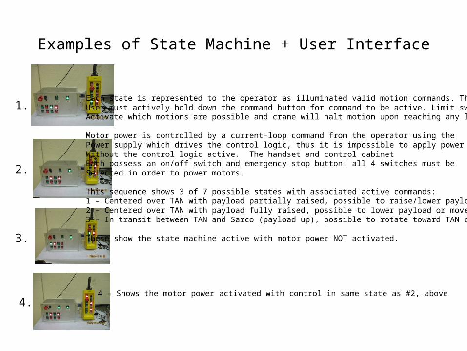
Each state is represented to the operator as illuminated valid motion commands. The User must actively hold down the command button for command to be active. Limit switchesActivate which motions are possible and crane will halt motion upon reaching any limit.
Motor power is controlled by a current-loop command from the operator using the Power supply which drives the control logic, thus it is impossible to apply power to motorsWithout the control logic active. The handset and control cabinetEach possess an on/off switch and emergency stop button: all 4 switches must be Selected in order to power motors.
This sequence shows 3 of 7 possible states with associated active commands: 1 – Centered over TAN with payload partially raised, possible to raise/lower payload only2 – Centered over TAN with payload fully raised, possible to lower payload or move to Sarco3 – In transit between TAN and Sarco (payload up), possible to rotate toward TAN or Sarco
These show the state machine active with motor power NOT activated.
1.
2.
3.
4.4 – Shows the motor power activated with control in same state as #2, above

Crane Transport: Surface to LHC Tunnel
Large structures are transported as 2 components:
1. Crane mounted on fixture. Fixture is a pedestalMounted onto a standard Sarco foot platform. Transported with standard pallet lifter.Mass < 400kgDimensions = 1550(l) x 670(w) x 1000(h)
Need to verify with transport clearance of object betweenPM56 elevator and Pt.5 TANs, left and right sides.
2. Standard CMS ZDC Sarco on platform. Transport in PM56 elevator and to TANs is already verified.
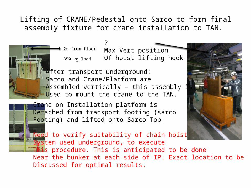
Lifting of CRANE/Pedestal onto Sarco to form finalassembly fixture for crane installation to TAN.
2,2m from floor?Max Vert positionOf hoist lifting hook350 kg load
Crane on Installation platform is Detached from transport footing (sarcoFooting) and lifted onto Sarco Top.
Need to verify suitability of chain hoist System used underground, to executeThis procedure. This is anticipated to be doneNear the bunker at each side of IP. Exact location to be Discussed for optimal results.
After transport underground:Sarco and Crane/Platform are Assembled vertically – this assembly isUsed to mount the crane to the TAN.

Bran Issues
1. The BRAN gas hoses interfere with a rotating drive shaft of the crane actuators.
This condition has been identified for 2 years and it has been agreed to be a Simple task to re-route the gas lines. However, it is important that specific plans areMade to accomplish this prior to crane installation. Components must be on hand, andThe task planned to execute this re-routing prior to crane installation.
2. The placement of the different elements (ZDC, BRAN, BARS) needs to be fully Understood. Currently it is believed that the BRAN is located in different positionsAlong the slot length, and the other elements shifted accordingly.
These are explained in more detail in the following slides.
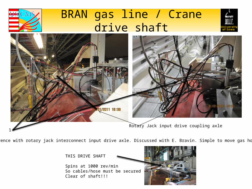
BRAN gas line / Crane drive shaft
1. Interference with rotary jack interconnect input drive axle. Discussed with E. Bravin. Simple to move gas hose.
1Rotary Jack input drive coupling axle
THIS DRIVE SHAFT
Spins at 1000 rev/min So cables/hose must be secured Clear of shaft!!!

Elements Placement in TAN slot
The “official” elements placement is shownAt left. This geometry was used to designThe fixation point locations of the craneAnd payloads.
It is NOT clearly understood that the currentState of elements in TAN conforms to thisGeometry.
Specifically, one BRAN is believed to be located at the nominal position centered at 200mm from the front (IP) side of slot and The other is offset.
The crane does not care where elements are placed, elements can be placed anywhere in the full slot length. BUT – movement in theZ axis is not an operational degree of freedom, these offsets are accomplished by offsets built into the payload attachment fixtures. These Fixtures are built elements and thus the element placements must be understood in advance.
Detector owners for the ZDC and BRAN must understand exactly where their detectors are currently placed, where they nominally Want them to be paced, and appropriate crane fixtures will be built to achieve this.

Schedule for Christmas 2012 break and LS1
The current planning is to reinstall the CMS ZDC manually without the use of the remote handling tool.Then installation of the remote handling tool occurs during LS1.
It may be possible to obtain approval for installation and operation of the remote handling tool to be usedFor CMS ZDC installation during Xmas break prior to the proton-ion run.
- This depends upon the completion of the documentation package in time for approvalAll documents submitted for review - Mid October 2012
- Also depends upon the successful demonstration of the emergency removal procedureDemonstration and documentation of emergency removal - Mid November 2012