cms – current measurement system user manual – current measurement system user manual document...
TRANSCRIPT
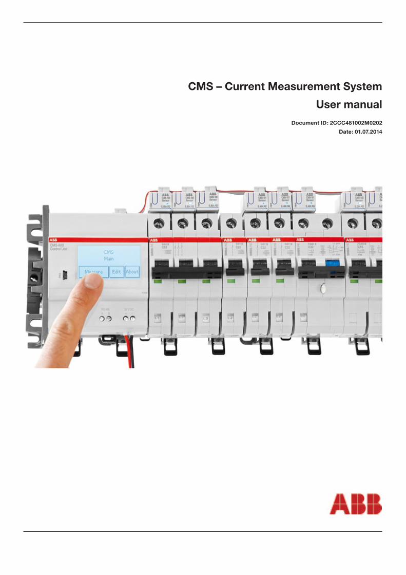
CMS – Current Measurement System
User manual
Document ID: 2CCC481002M0202
Date: 01.07.2014

CMS – Current Measurement System User manual2
Warning Failure to follow these instructions could result in death, personal injury or property damage. The device should be installed by a qualified person only. If the components or devices do not appear to be in a proper condition, they must be replaced. Please use only original compo-nents and accessories. The device should not come in contact with liquids.
CleaningOnly with dry cloth.
Disposal Faulty products should be treated as hazardous waste and disposed of in an appropri-ate manner. National or regional regulations regarding the disposal of hazardous waste
should be adhered to.
The information in this document is subject to change without notice and should not be con-strued as a commitment by ABB Ltd.. ABB Ltd. assumes no responsibility for any errors that may appear in this document.
In no event shall ABB Ltd. be liable for direct, indirect, special, incidental or consequential dam-ages of any nature or kind arising from the use of this document, nor shall ABB Ltd. be liable for incidental or consequential damages arising from use of any software or hardware described in this document.
This document and parts thereof must not be reproduced or copied without written permission from ABB Ltd., and the contents thereof must not be imparted to a third party nor used for any unauthorized purpose.
The software or hardware described in this document is furnished under a license and may be used, copied, or disclosed only in accordance with the terms of such license.
© Copyrigth 2012 ABB Ltd. All rights reserved.
ABB Ltd. is a registered trademark of the ABB Group. All other brand or product names mentioned in this document may be trademarks or registered trademarks of their respective holders.
WarningMay cause death or serious injury i Information that is useful or impor-
tant but not relevant to safety
European conformity mark0.5-0.6 Nm
Torque
Mind the instructions in the user manual
Disposal
Safety Precautions
Meaning of symbols
Disclaimer
Copyright
Trademark
CMS – Current Measurement System User manual3
Table of content
Intended use . . . . . . . . . . . . . . . . . . . . . . . . . . . . . . . . . . . . . . . . . . . . . . . . . . . . . . . . . . . . . . . . . . . . . . . . . . . . . . . . . . . 4
System overview . . . . . . . . . . . . . . . . . . . . . . . . . . . . . . . . . . . . . . . . . . . . . . . . . . . . . . . . . . . . . . . . . . . . . . . . . . . . . . . . 4
Scope of delivery . . . . . . . . . . . . . . . . . . . . . . . . . . . . . . . . . . . . . . . . . . . . . . . . . . . . . . . . . . . . . . . . . . . . . . . . . . . . . . . . 5
Mounting and cabling . . . . . . . . . . . . . . . . . . . . . . . . . . . . . . . . . . . . . . . . . . . . . . . . . . . . . . . . . . . . . . . . . . . . . . . . . . . . . 7
Mounting the Control Unit. . . . . . . . . . . . . . . . . . . . . . . . . . . . . . . . . . . . . . . . . . . . . . . . . . . . . . . . . . . . . . . . . . . . . 7
Mounting the pro M compact and SMISSLINE sensor . . . . . . . . . . . . . . . . . . . . . . . . . . . . . . . . . . . . . . . . . . . . . . . . 7
Mounting the S800 Sensor . . . . . . . . . . . . . . . . . . . . . . . . . . . . . . . . . . . . . . . . . . . . . . . . . . . . . . . . . . . . . . . . . . . . 7
Mounting the DIN-rail sensor . . . . . . . . . . . . . . . . . . . . . . . . . . . . . . . . . . . . . . . . . . . . . . . . . . . . . . . . . . . . . . . . . . 8
Mounting the cable sensor . . . . . . . . . . . . . . . . . . . . . . . . . . . . . . . . . . . . . . . . . . . . . . . . . . . . . . . . . . . . . . . . . . . . 8
Cabling the Control Unit . . . . . . . . . . . . . . . . . . . . . . . . . . . . . . . . . . . . . . . . . . . . . . . . . . . . . . . . . . . . . . . . . . . . . . 8
Cabling the sensors . . . . . . . . . . . . . . . . . . . . . . . . . . . . . . . . . . . . . . . . . . . . . . . . . . . . . . . . . . . . . . . . . . . . . . . . . 9
Control Unit . . . . . . . . . . . . . . . . . . . . . . . . . . . . . . . . . . . . . . . . . . . . . . . . . . . . . . . . . . . . . . . . . . . . . . . . . . . . . . . . . . . . 9
Menu overview. . . . . . . . . . . . . . . . . . . . . . . . . . . . . . . . . . . . . . . . . . . . . . . . . . . . . . . . . . . . . . . . . . . . . . . . . . . . . 9
Add and remove sensors . . . . . . . . . . . . . . . . . . . . . . . . . . . . . . . . . . . . . . . . . . . . . . . . . . . . . . . . . . . . . . . . . . . . 10
Change DC polarity of sensors . . . . . . . . . . . . . . . . . . . . . . . . . . . . . . . . . . . . . . . . . . . . . . . . . . . . . . . . . . . . . . . . 10
MODBUS configuration . . . . . . . . . . . . . . . . . . . . . . . . . . . . . . . . . . . . . . . . . . . . . . . . . . . . . . . . . . . . . . . . . . . . . 11
Display configuration . . . . . . . . . . . . . . . . . . . . . . . . . . . . . . . . . . . . . . . . . . . . . . . . . . . . . . . . . . . . . . . . . . . . . . . 11
Measurement functions . . . . . . . . . . . . . . . . . . . . . . . . . . . . . . . . . . . . . . . . . . . . . . . . . . . . . . . . . . . . . . . . . . . . . 12
MODBUS-Kommunikation . . . . . . . . . . . . . . . . . . . . . . . . . . . . . . . . . . . . . . . . . . . . . . . . . . . . . . . . . . . . . . . . . . . . . . . . 13
MODBUS communication protocol . . . . . . . . . . . . . . . . . . . . . . . . . . . . . . . . . . . . . . . . . . . . . . . . . . . . . . . . . . . . . 13
Communication to CMS . . . . . . . . . . . . . . . . . . . . . . . . . . . . . . . . . . . . . . . . . . . . . . . . . . . . . . . . . . . . . . . . . . . . . 14
Examples. . . . . . . . . . . . . . . . . . . . . . . . . . . . . . . . . . . . . . . . . . . . . . . . . . . . . . . . . . . . . . . . . . . . . . . . . . . . . . . . 20
Technical data . . . . . . . . . . . . . . . . . . . . . . . . . . . . . . . . . . . . . . . . . . . . . . . . . . . . . . . . . . . . . . . . . . . . . . . . . . . . . . . . . 21
FAQ . . . . . . . . . . . . . . . . . . . . . . . . . . . . . . . . . . . . . . . . . . . . . . . . . . . . . . . . . . . . . . . . . . . . . . . . . . . . . . . . . . . . . . . . . 23
Technical drawings. . . . . . . . . . . . . . . . . . . . . . . . . . . . . . . . . . . . . . . . . . . . . . . . . . . . . . . . . . . . . . . . . . . . . . . . . . . . . . 24
CMS – Current Measurement System User manual4
Control Unit
CMS-Bus interfaces Electrical line
DIN-rail (optional SMISSLINE TP)
CMS-Bus
CMS connectors
CMS Sensor
DIN-rail (optional SMISSLINE TP)
24V DC
RS485MODBUS RTU
Intended use
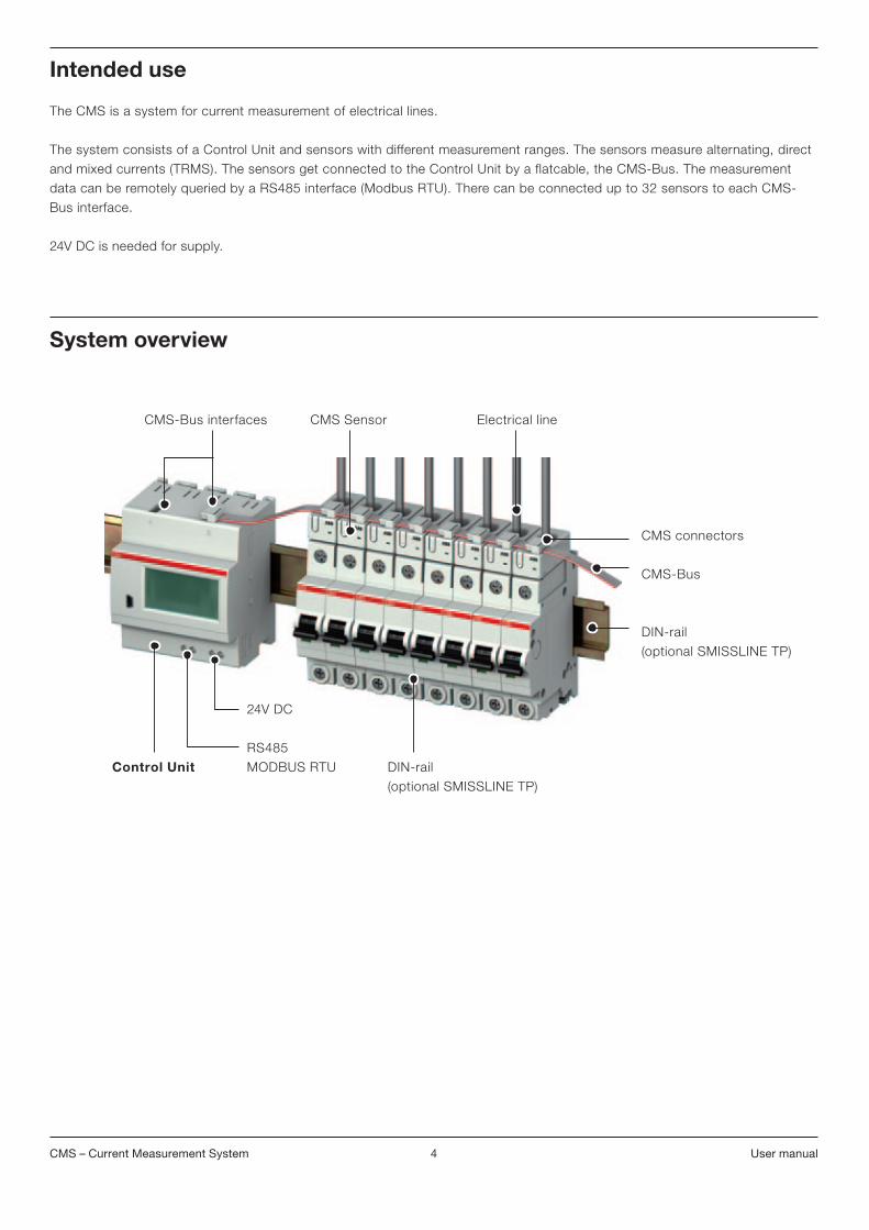
The CMS is a system for current measurement of electrical lines.
The system consists of a Control Unit and sensors with different measurement ranges. The sensors measure alternating, direct and mixed currents (TRMS). The sensors get connected to the Control Unit by a flatcable, the CMS-Bus. The measurement data can be remotely queried by a RS485 interface (Modbus RTU). There can be connected up to 32 sensors to each CMS-Bus interface.
24V DC is needed for supply.
System overview

CMS – Current Measurement System User manual5
Scope of delivery
CMS-Bus interfaces
Touchdisplay
Mini USB interface (no function)
Connecting terminals for 24 V DC
Connecting terminals for RS485
Control Unit CMS-600
Opening of sensor to lead through the electrical line
CMS-Bus interface
Push button
LED
Sensors
LED Status• On Normal operation• Slow blinking Sensor is not added to the system• Fast blinking Sensor is selected, ID is shown on touch display
i

CMS – Current Measurement System User manual6
35 x Connector housing 35 x Connector
Flat cable CMS-800 (2 m)
Flat cable CMS-801 (3 m)
Connector set CMS-820
Mounting pro M compact & SMISSLINE
S800 DIN-Rail Cable tie
for all ABB MCBs, RCDs, RCBOs with twin terminals
for all ABB S800 devices with cage terminals
universal use universal use
Sensor type
Sensors 18 mmCMS-100xx (80 A)CMS-101xx (40 A)CMS-102xx (20 A)
CMS-100PSCMS-101PSCMS-102PS
CMS-100S8CMS-101S8CMS-102S8
CMS-100DRCMS-101DRCMS-102DR
CMS-100CACMS-101CACMS-102CA
Sensors 25 mmCMS-200xx (160 A)CMS-201xx (80 A)CMS-202xx (40 A)
CMS-200S8CMS-201S8CMS-202S8
CMS-200DRCMS-201DRCMS-202DR
CMS-200CACMS-201CACMS-202CA

CMS – Current Measurement System User manual7
Mounting and cabling
Mounting the Control Unit
Mounting the M compact and SMISSLINE sensor
Mounting the S800 Sensor
DIN-rail mounting SMISSLINE TP mounting
1a
• Remove rapid fixation (RAFIX) before mount-ing on SMISSLINE TP
• Sensors fit to all the ABB installation devic-es with twin terminals
• The cable should not exert force to the sen-sor, otherwise measur-ing errors are possible
• The sensors can be mounted to all S800 devices with cage terminals
• The cable should not exert force to the sensor, otherwise measuring errors are possible
i
i
i
1b
or
«klick» «klick»
«klick»
1
1
Insert the metal pin of the sensor into the rear ter-minal connection
Put cable through opening of sensor into installation device. The cable has to be isolated within the range of the sensor, then thighten the screw.
Slip sensor on S800
2 3
2 3
Put cable through opening of sensor into installation device. The cable has to be isolated within the range of the sensor, then thighten the screw.
Unscrew the terminal of the installation device
Remove interchangeable adapter

CMS – Current Measurement System User manual8
Mounting the DIN-rail sensor
Mounting the cable sensor
Cabling the Control Unit
"Click" device on DIN rail
Put cable thorugh opening of sensor into installation device. Fix the cable with a cable tie.
Insert cables into the connecting terminals
Tighten the screws
Put cable through opening of sensor into installation device. Fix the cable with a cable tie if needed.
• The sensors can be mounted to 35mm DIN rail acc. EN 60715
• The cable should not exert force to the sensor, otherwise measuring errors are possible
• The cable should not exert force to the sensor, otherwise measuring errors are possible
Connecting terminals for 24 V DC and RS485:• max. cable cross-
section 2,5 mm2
• stripping length 13 mm• current consumption
of Control Unit max. 1.5 A
i
i
i
«klick»
1 2
1
11 2

CMS – Current Measurement System User manual9
Cabling the sensors
Menu overview
Put the flat cable onto the CMS-Bus interfaces
Put the connector at the position of the marking into the connector housing
Press together the connec-tor and the connector hous-ing with a parallel pliers tool. Repeat that process at the other markings.
Plug the connectors to the Control Unit and the sensors
Mark the desired placement of the connectors with a pen
Press the flat cable into the cable duct of the connector housing
• Use the connectors only once
• Connect a max. number of 32 sensors to each Control Unit CMS-Bus interface
• Do not exceed a maxi-mum line length of 2 m
• Flatcable should not exert force to the sensor, otherwise measuring errors are possible
• Keep a distance of min. 5.5 mm from the flat cable to unisolated live parts
i 1 2 3
4 5 6
Plug the connectors to the sensors with the longer side to the middle
7 7
Control Unit
CMSMain
CMSMain
About
Edit
Edit
Edit
Measure
Measure
Measure
Measurement functions of Control Unit
Addition and removal of sensors, change of DC polarity, Modus configuration, Display configu-ration
Information about serial number, hard- and software version of Control Unit
About

CMS – Current Measurement System User manual10
Add and remove sensors
Change DC polarity of sensors
Edit configuration
Remove ALL sensors?
Dis-play
No
Mod-bus
Yes
Exit
Remove sensor 1Select with up / down
or press button of sensor
Add sensor with ID 1Press button of sensor
Exit Re-move
Edit Sensors
Exit Add Set-tings
“Yes” to remove all sensors
Remove single sensors Push or until the desired sensor ID appears. Alternatively press push button of desired sensor.Press “Remove” to remove the selected sensor.
Push or until the desired sensor ID appears. Press push button of desired sensor to add sensor to the system.
i If sensor has an ID already, ID will be replaced
Remove sensors
Exit Single
Sen-sors
Re-move
All
Dis-play
Mod-busExit Sen-
sors
Change DC polarity for all sensors to reverse?
No Yes
ID1SID 8001201112190054HW 02,00 SW 01,05 Polarity Direct
Exit SwapPol
Edit Sensors
Edit configuration
Exit Add Re-move
Set-tings
Change DC polarity of all sensors
Change DC polarity of sensorsPress “Single” to change the previously selected sensor.
Push or until the desired sensor ID appears. Alternatively press push button of desired sensor.Information about serial number, hard- and software version of sensors.
Direct Reverse
Swap DC polarityto reverse?
Exit Single All

CMS – Current Measurement System User manual11
Edit configuration
Sen-sors
Dis-playExit
MODBUSParity: Even
MODBUSBaudrate: 19200
MODBUSID: 1
Exit
Exit
Exit
Enter
Enter
Enter
EditMODBUS RTUconfiguration
Exit Setting of MODBUS data format (parity).Press or to change between odd, even and none parity.
Setting of MODBUS data rate.Press or to change between baudrates.
Setting of Control Unit‘s MODBUS ID
Mod-bus
ID Baud Parity
MoDbUS configuration
Display configuration
Edit configuration
Sen-sors
Mod-busExit
Beep
EditDisplay
Configuration
Exit Enter
Exit
Key click
Timeout for light2 min
Exit
Exit
Enter
Enter
Switch signal and touch tones on or off
Settings for timeout of lighting of background and sensor LEDs
Settings for brightness and contrast of display
Dis-play
BrightContr
Timeout Beep

CMS – Current Measurement System User manual12
Measure
ID 1 TRMS
ID 1
ID 1
Min
Hold value
MaxTRMS
TRMS
actual ACDC
ACDC
ACDC
Exit
Actual value
Exit Holdall
Exit
Exit Reset
Advanced measurementNOTE: while Hold/Reset
MODBUS is disabled
Reset Min / Max Valuesof all Sensors?
Exit
Exit
Hold
OK
Resetall
MinMax Reset minimum and maximum values of all sensors
Shows minimum and maximum values since the last system start or reset. “Reset” resets the minimum and maximum values of the selected sensor.
Pressing “Hold all” stores all the actual measurement values of all sensors into the Control Unit. Pressing “Hold all” again overwrites all present values.
Shows the actual measurement values
i Selection of desired sensor ID
• Press or until the desired sensor ID appears• Press push button of desired sensorMore
Measurement functions
CMS – Current Measurement System User manual13
MoDbUS frame description (RTU mode)
Introducing MoDbUS protocol
MoDbUS data encoding MODBUS uses a big endian allocation for addresses and data items. This means, when a nu-merical quantity larger than a single byte is transmitted, the most significant byte is sent first. Example: 1234h first 12h then 34h
MoDbUS communication protocol
MoDbUS-Kommunikation
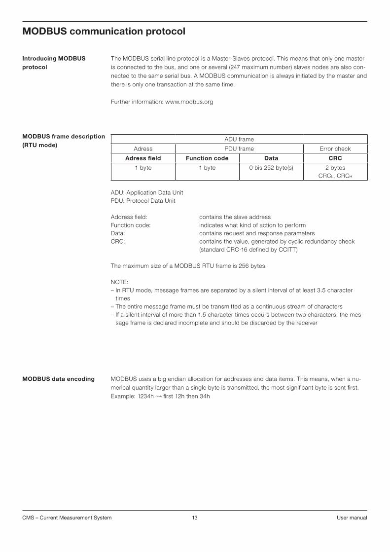
The MODBUS serial line protocol is a Master-Slaves protocol. This means that only one master is connected to the bus, and one or several (247 maximum number) slaves nodes are also con-nected to the same serial bus. A MODBUS communication is always initiated by the master and there is only one transaction at the same time.
Further information: www.modbus.org
ADU: Application Data UnitPDU: Protocol Data Unit
Address field: contains the slave addressFunction code: indicates what kind of action to performData: contains request and response parametersCRC: contains the value, generated by cyclic redundancy check (standard CRC-16 defined by CCITT) The maximum size of a MODBUS RTU frame is 256 bytes.
NOTE:– In RTU mode, message frames are separated by a silent interval of at least 3.5 character
times– The entire message frame must be transmitted as a continuous stream of characters– If a silent interval of more than 1.5 character times occurs between two characters, the mes-
sage frame is declared incomplete and should be discarded by the receiver
ADU frame
Adress PDU frame Error check
Adress field Function code Data CRC
1 byte 1 byte 0 bis 252 byte(s) 2 bytesCRCL, CRCH

CMS – Current Measurement System User manual14
Physical interface RS-485 To communicate with the CMS by an upper system all devices (masters & slaves) must have the same data rate and data format.These settings are done over the Control Unit’s touch display, as described in chapter “MOD-BUS configuration”.
Parameter Values Default values
Data rate 2400, 4800, 9600, 19200, 38400, 57600, 115200 Bit/s
19200 Bit/s
Data format even parity, odd parity, without parity even parity
Line termination: external, if necessary
Control Unit’s MoDbUS-ID
Function code • Read operation on registers with access code “R” or “RW” is defined by function 03h «Read Holding Registers» • Write operation on registers with access code “W” or “RW” is defined by function
06h «Write Single Register»
Other than the specified functions must not be applied.
It is possible to connect up to 247 Control Units to one MODBUS RTU line. Each Control Unit must have an unique MODBUS ID (address), according the description in the chapter “MODBUS configuration”.
These IDs can be set over the Control Unit’s touch display.
Default ID (address): 1
Communication to CMS
CMS – Current Measurement System User manual15
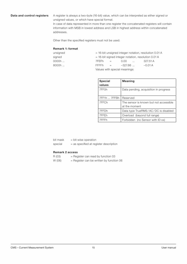
Data and control registers A register is always a two-byte (16-bit) value, which can be interpreted as either signed or unsigned values, or which have special format. In case of data represented in more than one register the concatenated registers will contain information with MSB in lowest address and LSB in highest address within concatenated addresses.
Other than the specified registers must not be used.
Remark 1: formatunsigned = 16-bit unsigned integer notation, resolution 0.01 Asigned = 16-bit signed integer notation, resolution 0.01 A 0000h ... 7FEFh = 0.00 ... 327.51 A 8000h ... FFFFh = –327.66 ... –0.01 A Values with special meanings:
bit mask = bit-wise operationspecial = as specified at register description
Remark 2 accessR (03) = Register can read by function 03W (06) = Register can be written by function 06
Special values
Meaning
7FF0h Data pending, acquisition in progress
7FF1h ... 7FFBh Reserved
7FFCh The sensor is known but not accessible at the moment
7FFDh Data type TrueRMS / AC / DC is disabled
7FFEh Overload (beyond full range)
7FFFh Forbidden (no Sensor with ID xx)

CMS – Current Measurement System User manual16
Measured minimal values These registers contain the minimal measured values since last system start / reset or since last request “reset min/max values”.
ongoing measurement These registers contain the actual measured data.values
Adress (hex)
Words (16bit)
Description Resolu-tion and unit
Format 1 Access 2
0400 1 TrueRMS min value of Sensor 1 0.01 A unsigned R (03)
0401 1 TrueRMS min value of Sensor 2 0.01 A unsigned R (03)
… 1 … 0.01 A unsigned R (03)
043E 1 TrueRMS min value of Sensor 63 0.01 A unsigned R (03)
043F 1 TrueRMS min value of Sensor 64 0.01 A unsigned R (03)
0500 1 AC min value of Sensor 1 0.01 A unsigned R (03)
0501 1 AC min value of Sensor 2 0.01 A unsigned R (03)
… 1 … 0.01 A unsigned R (03)
053E 1 AC min value of Sensor 63 0.01 A unsigned R (03)
053F 1 AC min value of Sensor 64 0.01 A unsigned R (03)
0600 1 DC min value of Sensor 1 0.01 A signed R (03)
0601 1 DC min value of Sensor 2 0.01 A signed R (03)
… 1 … 0.01 A signed R (03)
063E 1 DC min value of Sensor 63 0.01 A signed R (03)
063F 1 DC min value of Sensor 64 0.01 A signed R (03)
Adress (hex)
Words (16bit)
Description Resolu-tion and unit
Format 1 Access 2
0000 1 TrueRMS Wert of SENSOR 1 0.01 A unsigned R (03)
0001 1 TrueRMS Wert of SENSOR 2 0.01 A unsigned R (03)
… 1 … 0.01 A unsigned R (03)
003E 1 TrueRMS Wert of SENSOR 63 0.01 A unsigned R (03)
003F 1 TrueRMS Wert of SENSOR 64 0.01 A unsigned R (03)
0100 1 AC value of Sensor 1 0.01 A unsigned R (03)
0101 1 AC value of Sensor 2 0.01 A unsigned R (03)
… 1 … 0.01 A unsigned R (03)
013E 1 AC value of Sensor 63 0.01 A unsigned R (03)
013F 1 AC value of Sensor 64 0.01 A unsigned R (03)
0200 1 DC value of Sensor 1 0.01 A signed R (03)
0201 1 DC value of Sensor 2 0.01 A signed R (03)
… 1 … 0.01 A signed R (03)
023E 1 DC value of Sensor 63 0.01 A signed R (03)
023F 1 DC value of Sensor 64 0.01 A signed R (03)

CMS – Current Measurement System User manual17
Adress (hex)
Words (16bit)
Description Resolu-tion and unit
Format 1 Access 2
0800 1 TrueRMS max value of Sensor 1 0.01 A unsigned R (03)
0801 1 TrueRMS max value of Sensor 2 0.01 A unsigned R (03)
… 1 … 0.01 A unsigned R (03)
083E 1 TrueRMS max value of Sensor 63 0.01 A unsigned R (03)
083F 1 TrueRMS max value of Sensor 64 0.01 A unsigned R (03)
0900 1 AC max value of Sensor 1 0.01 A unsigned R (03)
0901 1 AC max value of Sensor 2 0.01 A unsigned R (03)
… 1 … 0.01 A unsigned R (03)
093E 1 AC max value of Sensor 63 0.01 A unsigned R (03)
093F 1 AC max value of Sensor 64 0.01 A unsigned R (03)
0A00 1 DC max value of Sensor 1 0.01 A signed R (03)
0A01 1 DC max value of Sensor 2 0.01 A signed R (03)
… 1 … 0.01 A signed R (03)
0A3E 1 DC max value of Sensor 63 0.01 A signed R (03)
0A3F 1 DC max value of Sensor 64 0.01 A signed R (03)
Measured maximal values These registers contain the maximal measured values since last system start / reset or since last request “reset min/max values”.
Measured hold values These registers contain the hold values captured at a time given by request “trigger hold measurement”.
Adress (hex)
Words (16bit)
Description Resolu-tion and unit
Format 1 Access 2
0C00 1 TrueRMS hold value of Sensor 1 0.01 A unsigned R (03)
0C01 1 TrueRMS hold value of Sensor 2 0.01 A unsigned R (03)
… 1 … 0.01 A unsigned R (03)
0C3E 1 TrueRMS hold value of Sensor 63 0.01 A unsigned R (03)
0C3F 1 TrueRMS hold value of Sensor 64 0.01 A unsigned R (03)
0D00 1 AC hold value of Sensor 1 0.01 A unsigned R (03)
0D01 1 AC hold value of Sensor 2 0.01 A unsigned R (03)
… 1 … 0.01 A unsigned R (03)
0D3E 1 AC hold value of Sensor 63 0.01 A unsigned R (03)
0D3F 1 AC hold value of Sensor 64 0.01 A unsigned R (03)
0E00 1 DC hold value of Sensor 1 0.01 A signed R (03)
0E01 1 DC hold value of Sensor 2 0.01 A signed R (03)
… 1 … 0.01 A signed R (03)
0E3E 1 DC hold value of Sensor 63 0.01 A signed R (03)
0E3F 1 DC hold value of Sensor 64 0.01 A signed R (03)

CMS – Current Measurement System User manual18
Trigger hold, reset min and max values
Write operation on this register • triggers the hold measurement of all sensors, and / or• resets the minimal and maximal values of all sensors
Adress (hex)
Words (16bit)
Description Resolu-tion and unit
Format 1 Access 2
3010 1 Trigger hold, reset min and max values
bit mask W (06)
The commands have the following bit format position:
0000 0000 000T 000R
• T 1 = Trigger hold measurement• R 1 = Reset min and max values
Command will be acknowledged by response message on MODBUS and by a short display message.
Example: 0010h means "Trigger hold measurement"

CMS – Current Measurement System User manual19
Show Sensor Write operation on this register starts or stops fast LED blinking of one specified Sensor for diagnosis purpose.
Adress (hex)
Words (16bit)
Description Resolu-tion and unit
Format 1 Access 2
3011 1 Show Sensor special W (06)
Start / stop command is in the following bit format position:
000S 0000 0CCC CCCC
• C Sensor ID• S 0 = stop fast LED blinking 1 = start fast LED blinking
Data written has to specify a known Sensor ID. Touch display is locked while showing Sensor, unlocked by stop blinking.
Example: 0x1017 means “Start fast LED blinking of Sensor with ID 23”
• When Sensor is addressed correctly, common response will follow• When Sensor ID is not used in system, exception response with MODBUS exception code 03h
“illegal data value” will follow. (If the fast LED blinking was active before, it will be stopped and Touch Display will be un-locked.)
Return to normal display content is possible by sending the stop command.
Error codes MODBUS protocol defines a common way of error reporting. Every request (read or write) sent in unicast mode is expected to return a value in packet of the same structure. In case of error in handing message (not CRC problems but message execution problems), generated response contains function code with MSB set (80h) and single byte representing error code, called “ex-ception code”.
The following default exception codes are provided:
Code Name Description
01h Illegal function Function is not supported
02h Illegal data address Register address is out of Control Unit’s range, or trying to write into a read only register
03h Illegal data value Value is out of range
04h Slave device failure Unrecoverable error occurred while Control Unit was attempt-ing to perform the requested action, e.g. time-out
06h Slave device busy Control Unit is currently in User-Interface-Configuration-Mode. The requested action is not possible.

CMS – Current Measurement System User manual20
Examples
To introduce basics of the communication scheme, the most common use cases are described. Note: The described use cases do not cover all possibilities but only shows example communi-cation schemes
Read ongoing measure-ment values of Sensor 5-16
Trigger hold function of all Sensors
frames comment
M➞S D03h 00h, 04h00h, 0ChCRCL, CRCH
MBID address of Control UnitFunction code (Read Holding Registers)Starting address (TrueRMS value of Sensor 5)Quantity of registers (12)CRC
S➞M ID03h 18hVALUEH , VALUEL
VALUEH , VALUEL
VALUEH , VALUEL
VALUEH , VALUEL
VALUEH , VALUEL
VALUEH , VALUEL
VALUEH , VALUEL
VALUEH , VALUEL
VALUEH , VALUEL
VALUEH , VALUEL
VALUEH , VALUEL
VALUEH , VALUEL
CRCL, CRCH
MBID address of Control UnitFunction code (Read Holding Registers)Quantity of bytes (24)Register value (TrueRMS value of Sensor 5)Register value (TrueRMS value of Sensor 6)Register value (TrueRMS value of Sensor 7)Register value (TrueRMS value of Sensor 8)Register value (TrueRMS value of Sensor 9)Register value (TrueRMS value of Sensor10)Register value (TrueRMS value of Sensor11)Register value (TrueRMS value of Sensor12)Register value (TrueRMS value of Sensor13)Register value (TrueRMS value of Sensor14)Register value (TrueRMS value of Sensor15)Register value (TrueRMS value of Sensor16)CRC
frames comment
M➞S ID06h 30h, 10h00h, 10hCRCL, CRCH
MBID address of Control UnitFunction code (Write Single Register)Register address (Trigger hold, reset min / max)Register value (Trigger hold)CRC
S➞M ID06h 30h, 10h00h, 10hCRCL, CRCH
MBID address of Control UnitFunction code (Write Single Register)Register address (Trigger hold, reset min / max)Register value (Trigger hold)CRC

CMS – Current Measurement System User manual21
Technical data
Sensors 18 mm
Sensor type CMS-100xx CMS-101xx CMS-102xx
Measurement range [A] 80 40 20
Measurement method TRMS, AC 50/60 Hz, DC TRMS, AC 50/60 Hz, DC TRMS, AC 50/60 Hz, DC
Crest factor of distorted wave forms ≤ 1.5 ≤ 3 ≤ 6
AC Accuracy (TA = +25 °C)* ≤ ± 0.5 % ≤ ± 0.5 % ≤ ± 0.5 %
AC Temperature coefficient* ≤ ± 0.036 % ≤ ± 0.036 % ≤ ± 0.036 %
DC Accuracy (TA = +25 °C)* ≤ ± 0.7 % ≤ ± 1.0 % ≤ ± 1.7 %
DC Temperature coefficient* ≤ ± 0.047 % ≤ ± 0.059 % ≤ ± 0.084 %
Resolution [A] 0.01 0.01 0.01
Sampling rate internal [Hz] 5000 5000 5000
Settling time (±1%) [sec] typ. 0.25 typ. 0.25 typ. 0.25
Cable feed through [mm] 10 10 10
Insulation voltage [V] 690 VAC/1500 VDC 690 VAC/1500 VDC 690 VAC/1500 VDC
Dimensions
CMS-100PS series [mm] 17.4 x 41.0 x 26.5 17.4 x 41.0 x 26.5 17.4 x 41.0 x 26.5
CMS-100S8 series [mm] 26.5 x 45.5 x 31.8 26.5 x 45.5 x 31.8 26.5 x 45.5 x 31.8
CMS-100DR series [mm] 17.4 x 51.5 x 43.2 17.4 x 51.5 x 43.2 17.4 x 51.5 x 43.2
CMS-100CA series [mm] 17.4 x 41.0 x 29.0 17.4 x 41.0 x 29.0 17.4 x 41.0 x 29.0
Sensors 25 mm
Sensor type CMS-200xx CMS-201xx CMS-202xx
Measurement range [A] 160 80 40
Measurement method TRMS, AC 50/60 Hz, DC TRMS, AC 50/60 Hz, DC TRMS, AC 50/60 Hz, DC
Crest factor of distorted wave forms ≤ 1.5 ≤ 3 ≤ 6
AC Accuracy (TA = +25 °C)* ≤ ± 0.5 % ≤ ± 0.5 % ≤ ± 0.5 %
AC Temperature coefficient* ≤ ± 0.036 % ≤ ± 0.036 % ≤ ± 0.036 %
DC Accuracy (TA = +25 °C)* ≤ ± 0.7 % ≤ ± 1.0 % ≤ ± 1.7 %
DC Temperature coefficient* ≤ ± 0.047 % ≤ ± 0.059 % ≤ ± 0.084 %
Resolution [A] 0.01 0.01 0.01
Sampling rate internal [Hz] 5000 5000 5000
Settling time (±1%) [sec] typ. 0.25 typ. 0.25 typ. 0.25
Cable feed through [mm] 15 15 15
Insulation voltage [V] 690 VAC/1500 VDC 690 VAC/1500 VDC 690 VAC/1500 VDC
Dimensions
CMS-200S8 series [mm] 26.5 x 43.0 x 38.5 26.5 x 43.0 x 38.5 26.5 x 43.0 x 38.5
CMS-200DR series [mm] 25.4 x 43.0 x 43.2 25.4 x 43.0 x 43.2 25.4 x 43.0 x 43.2
CMS-200CA series [mm] 25.4 x 43.0 x 35.7 25.4 x 43.0 x 35.7 25.4 x 43.0 x 35.7
* All accuracy values refer to full range

CMS – Current Measurement System User manual22
General Data Sensors and Control Unit
Operating temperature –25 °C .. +65 °C
Storage temperature –40 °C .. +85 °C
Altitude Up to 2000 m
Maximum relative humidity 80 % for temperatures up to 31 °C decreasing linearly to 50 % relative humidity at 40 °C
Usage Within enlosures and combiner boxes
Shock resistance 5 g, 6 shocks, duration 30 ms, acc. IEC 60068-2-27 Ea
Power consumption 4 W–24 W (depending on no. of sensors)
Protection No external protection needed, contains internal self resetting fuse
Vibration resistance 1 g, 20 cyclus, 5…150…5 Hz, acc. IEC 60068-2-6 Fc
Overvoltage category Cat. II, acc. EN 50178
Pollution degree Class 3 – Ui 690 V AC / Class 2 – Ui 1500 V DC, acc. EN 50178
Environment class Type B, acc. EN 50178, 6.1
Rated impulse withstand capability 4 kV, acc. EN 50178
Electrostatic discharge (ESD) 8 kV air discharge, 6 kV contact discharge, acc. IEC/EN 61000-4-2, crit. b
EMC IEC/EN 61000-4-3, -4-4, -4-5, -4-6, -6-3, -6.4
Immunity to radiated electromagnetic fields
(RFI
10 V/m, acc. IEC/EN 61000-4-3, crit. a
Immunity to fast transient burst 4 kV power cables, 2 kV signal cables, acc. IEC/EN 61000-4-4, crit. b
Immunity to high-energy pulses (surge) 0.5 kV DC power cable line-to-earth, 0.5 kV DC power cable line-to-line, 2 kV signal cable line-to-earth,
1 kV signal cable line-to-line, acc. IEC/EN 61000-4-5, crit. b
Immunity to line-conducted interference 10 V, acc. IEC/EN 61000-4-6, crit. b
Emission acc. IEC/EN 61000-6-3 and IEC/EN 61000-6-4
Control Unit
Supply voltage [VDC] 24 (±10 %)
Power consumption [W] 4–24 (depending on no. of sensors)
Interface RS485 2-wire
Protocol Modbus RTU
Data rate [Baud] 2400 … 115 200
Data refresh time ≤ 1 sec for 64 sensors’ results
Insulation Voltage [VAC] 400
Screw-type terminals 0.5 … 2.5 mm2, max 0.6 Nm
Mounting DIN-rail 35 mm acc. DIN50022 or SMISSLINE TP busbar system
Protection No external protection needed, contains internal self resetting fuse
Dimension [mm] 71.8 x 87.0 x 64.9 (4 DIN modules)
Technical data

CMS – Current Measurement System User manual23
FAQ
It can happen, that the CMS-system deviates from the expected state. Read the following special note, which should help you to identify possible problems.
behavior Explanation Remedy
Touch display of Control Unit does not show anything
Power supply is interrupted Check the power supply, turn on the power supply
The touch display of the Control Unit does not react on inputs
Entry is not recognized Press harder
Dirtiness Cleaning of the hand/ display
Devices is stuck in an infinite loop Reset system by interrupting the power supply
Sensor LED remains dark CMS-Bus connection is interrupted Check the flat cable and connection
Power supply of the CMS system is interrupted Check the power supply of the Control Unit
System is in “Time out for light” Touch the display, if desired increase the “Time out for light”
Sensor LED lights up continuously Normal function of a registered sensor If desired, decrease the “Time out for light”
Sensor LED blinks slowly Normal function of an unregistered sensor If desired, add sensor
Sensor LED blinks fast Normal function of a selected sensor If desired, select another sensor
Sensor LEDs and the illumination of touch display turn off too early / too late /never
“Time out for light” was not configured appropriately Configure the parameter “Edit Display Time out”
Sensor does not react on pressure on push button
The input is not recognized Press harder
Unexpected input, sensor selection is not allowed Use a function of the Control Unit, which is allowed for sensor selection
CMS-Bus connection of the sensor is interrupted Check flat cable and connection
Power supply of the CMS system is interrupted Check the power supply of the Control Unit
Adding a sensor is not possible The maximum amount of 32 sensors for CMS-Bus line is reached
Connect maximum 32 sensors to each busline
Pressure on the push button is not recognized Push harder
CMS-Bus connection of the sensor is interrupted Check flat cable and connections
Power supply of the CMS system is interrupted Check power supply of Control Unit
DC value of a sensor is shown with an incorrect polarity
DC polarity does not correspond to the desired cur-rent direction
Change DC polarity via Control Unit
No MODBUS function Cable connection is broken Check the bus cabling
False address Check MODBUS ID of Control Unit
Incorrect communications parameters Check MODBUS baudrate and parity settings
Incorrect communication protocol Use MODBUS RTU protocol
Reflections in the bus cable for bus length Use external line termination (resistor)
No USB function USB interface is currently only for firmware update Do Data connection via MODBUS terminals

CMS – Current Measurement System User manual24
Technical drawings
Sensor CMS-100PS series
Sensor CMS-100S8 series
1.3
5
41
17.40
26.50
14.
35
View 3D (M1:1)
14
22.50
31.80
45.
5
LED
15.80 1.50
27.80
6.9
5
41
17.40
14.
35
9.9
LED View 3D (M1:1)

CMS – Current Measurement System User manual25
Sensor CMS-100DR series
Sensor CMS-100CA series
43.20
15.80
35.60
19.80
17.40
41
2.4
5
51.
45
10.
45
14.
35
9.9
LED
manuelle Betätigung
View 3D (M1:1)
15.90
29
24.
6
14.
35
41
17.40
9.9
LED
manuelle Betätigung
View 3D (M1:1)

CMS – Current Measurement System User manual26
20.65 15
35.65
2.4
15
25.40
15.
80
43
17.
40
LED View 3D(M1:1)
50.
1 7
.05
43.20
20.65 21.60 15
17.40
25.40
15.
80
43
LED
View 3D (M1:1)
Sensor CMS-200DR series

CMS – Current Measurement System User manual27
20.65
29.15
17.80
45.
5
15
15.
80
1.3
0
43
25.40
26.50 LED
View 3D (M1:1)
Sensor CMS-200S8 series
Control Unit CMS-600
35 45
21.3
43.3
87
17.
5
71.8 50.4
64.9
1 2

CMS – Current Measurement System User manual28
BelgiumABB ELECTRO n.v.Hoge Wei, 271930 ZaventemBelgiumTelephone +32 (0) 27 18 63 11Telefax +32 (0) 27 18 66 66
www.abb.be
BrasilABB LtdaAv. dos Autonomistas, 149606020-902-Osasco-SPBrasilTelephone +55 (0) 80 00 14 91 11Telefax +55 (11) 36 88 99 77
www.abb.com.br
Czech RepublicABB s.r.o.Herspická 1361900 BrnoCzech RepublicTelephone +420 54 31 45 50 3Telefax +420 54 32 43 48 9
www.abb.cz/elsynn
DenmarkABB ASMeterbuen 332740 SkovlundeDenmarkTelephone +45 44 50 44 50Telefax +45 44 50 44 60
www.abb.dk
FinlandABB OYDomestic SalesHiomotie 13P.O. Box 18400381 HelsinkiFinlandTelephone +358 10 22 20 00Telefax +358 10 22 22 91 3
www.abb.fi
FranceABB EntrelecDivision Commercial France300 rue des Prés SeigneursZA La Boisse – BP 9014501124 Montluel CedexFranceTelephone +33 (0) 825 38 63 55Telefax +33 (0) 825 87 09 26
www.abb.fr Due to possible changes in design and materials, the properties and dimensions contained in this catalogue should only be viewed as binding upon confirmation from ABB.
Great BritainABB LimitedTower CourtFoleshill Enterprise ParkCourtaulds WayConventryCV6 5NXEnglandTelephone +44 (0) 24 76 36 85 00Telefax +44 (0) 24 76 36 44 99
www.abb.co.uk
IrelandAsea Brown Boveri Ltd.Belgrad Road, TallaghtDublin 24IrelandTelephone +35 31 40 57 30 0Telefax +35 31 40 57 33 2
www.abb.com/lowvoltage
ItalyABB SACE S.p.A.Line Protection DevicesViale dell’Industria, 1820010 Vittuone (MI)ItalyTelephone +39 02 90 34 1Telefax: +39 02 90 34 76 09
www.abb.it
NetherlandABB b.v.Automation ProductsGeorge Hintzenweg 813068 AV RotterdamPostbus 3013000 AH RotterdamNetherlandTelephone +31 (0) 10 40 78 91 1Telefax +31 (0) 10 40 78 09 0
www.abb.nl
NorwayABB ASJacob Borchsgt. 6P.O. Box 797 Brakeroya3002 DrammenNorwayTelephone +47 32 24 80 00Telefax +47 32 24 79 34
www.abb.no
PolandABB Sp. z o. o.Automation Productsul. Zeganska 104-713 WarszawaPolandTelephone +48 22 51 64 441Telefax +48 22 51 64 444
www.abb.pl
P.R. ChinaABB (China) LtdUniversal Plaza, 10 Jiuxianqiao LuChaoyang District100016 BeijingP.R. ChinaTelephone +86 10 8456 6688Telefax +86 10 8456 9907
www.abb.com.cn
Russian FederationABB Industrial & Building Systems Ltd.30/1, bld. 2 Obrucheva St.117861 Moscow, RussiaTelephone +7 495 960 2200Telefax +7 495 960 2220
www.abb.ru/ibs
SingaporeABB Pte Ltd2 Ayer Rajah CrescentSingapore 139935Main Tel +65 6776 5711Main Fax +65 6778 0222
www.abb.com.sg
SpainABB Automation Products, S.A.c/Torrent d’Olla, 22008012 BarcelonaSpainTelephone +34 93 48 42 10 4Telefax +34 93 48 42 20 1
www.abb.es
SwedenABB AutomationTechnologies Cewe ControlMotorgräd 2072161 VästerasSwedenTelephone +46 (0) 21 32 07 00Telefax +46 (0) 21 12 60 01
www.abb.se
Contact