closed loop pi control for solar fed switched reluctance...
TRANSCRIPT

International Journal of Latest Engineering Research and Applications (IJLERA) ISSN: 2455-7137
Volume – 02, Issue – 10, October – 2017, PP – 64-77
www.ijlera.com 2017 IJLERA – All Right Reserved 64 | Page
Closed loop pi control for solar fed switched reluctance motor
drive based water pumping system
K. Chinababu1,Ch. Rajesh
2
1(EEE,PG Student, LBRCE/ JNTUK,INDIA)
2(EEE,.AsstProfessor,LBRCE/ JNTUK, INDIA)
Abstract: This paper demonstrates the utilization of solar photovoltaic (SPV) array produced electrical energy
for low cost and efficient water pumping using simple, robust and efficient switched reluctance motor (SRM)
drive. For increasing the efficiency of pumping system, an incremental conductance (Inc.) algorithm based
MPPT technique is employed with SRM drive. A DC-DC cuk converter operated in continuous conduction
mode (CCM) .The Mid-point converter having two split capacitors is used to provide the required voltage pulses
for phase windings excitation of all four phases of SRM drive. The mid-point converter operates as an electronic
commutator to reduce the switching losses and power dissipation of the converter. Both the inductors of cuk
converter are operated in continuous conduction mode (CCM) which results in minimal stress on converter
elements. The design of control system for four phase SRM is very complex since it has large torque ripples and
non uniform torque at its output. The reduction in torque ripples and speed control requires an effective
controller.the simulation of the PI based controller for SRM is performed by using MATLAB/simulink it
depends upon the different environmental conditions.
Keywords:SPV Array, MPPT, soft starting, SRM, water pump, incremental conductance (InC) , pi controller.
I. INTRODUCTION Now a day‟s solar photovoltaic (SPV) array based water pumping system is usually taken into practice
for extracting clean drinking water and irrigation purposes. Improving the efficiency of water pumps has many
advantages including increasing the profitability. The variable speed drive method of water pumping system
enhances the opportunity to reduce energy requirement [1] An 8/6 configuration of switched reluctance motor
(SRM) has become one of the most suitable and prominent machine for water pumping as an adjustable speed
drive [2]. The properties of SRM drive [3] which make it suitable for water pumping is its special mid-point
converter that is immune to shoot-through fault and only one switch per phase requirement for phase
energization. Unlike permanent magnet brushless DC motor and permanent magnet synchronous motor which
are giving very deficient performance with unipolar converter control, SRM is suitable for unipolar excitation
and low cost applications[4] The complete discussion on different converter topologies convenient for reduced
cost SRM drive has been discussed in [5-6] and concluded that mid-point converter is one of the suitable
candidate for high efficient low cost SRM drive. An efficient method of MPPT techniquecalled incremental
conductance (InC) method of SPV array has been discussed in [7]. Several researchers have demonstrated the
water pumping application of SRM motor. An InC algorithm of MPPT has several benefits over others like its
simplicity to implement and good performance under varying solar insolation levels [8].
The rotor of SRM contains no conductors or PMs [9]. Because of its high torque density, low inertia,
quick response, variable losses, and wide speed range capability, SRM could be a suitable candidate for water
pumping powered by SPV array. Moreover, the stator windings of SRM are electrically separated; hence, the
choice of converter topology and control strategy has more flexibility than any other drive system [10], [11]It
consists a storage batteryconnected to the SPV array through a battery voltage regulator (BVR) with the help of
two switches. So apart from battery issues, switching losses are also increased. Moreover addition to these
losses, absence of MPPT algorithm also decreases the efficiency of system. The switching losses are minimized
by using a concept of variable dc-link voltage for speed control of motor drive . A solar-powered pumping
system isngenerally in the same price range as a new windmill but tends to be more reliable and require less
maintenance. A solar-powered pumping system generally costs more initially than a gas, diesel, or propane-
powered generator but again requires far less maintenance and labour . It is common to use diesel to power
generatorsin agricultural operations. A switched reluctance motor is a brushless AC motor which has simple
construction and does not require permanent magnet for its operation. Hence it has many advantages over other
dc or ac machines. The stator and rotor in SRM have salient poles and the of poles depends on the number of
phases. Normally two stator poles at opposite ends are configured to form one phase. The number of stator poles
is always different from that of rotor poles. SR motor has the phase winding on its stator and concentrated

International Journal of Latest Engineering Research and Applications (IJLERA) ISSN: 2455-7137
Volume – 02, Issue – 10, October – 2017, PP – 64-77
www.ijlera.com 2017 IJLERA – All Right Reserved 65 | Page
windings are used. The windings are inserted into the stator poles and connected in series to form one phase of
the motor. SR motor has the phase winding on its stator only and concentrated windings are used. The windings
are inserted into the stator poles and connected in series to form one phase of the motor. In a five phase SRM
there are five pairs of concentrated windings and each pair of the winding is connected in series to form each
phase respectively.
The flux linkage, inductance and torque characteristics vary with rotor position (i.e. the relative
position of the rotor pole with the stator pole). The flux linkage, inductance and torque characteristics of a SR
motor are highly non-linear. Positive torque in a SR motor is available at half the rotor pole pitch. Torque
production in an SR motor can be explained based on energy conversion process.
The popular electronic method for torque ripple reduction is based on the optimization of control
principles. This includes the supply voltage, turn–on and turn–off angles of the converter and current levels. But
overall torque will be reduced.Precise control of SRM model is not easy using conventional method (like PI)as
its flux linkage, inductance, and torque possess mutual coupling with rotor position and phase current.
II. PROPOSED SYSTEM CONFIGURATION The proposed solar-PV array fed water pumping system is designed for a 900 w solar PV array using a
cukconverter with MPPT control, a mid-point converter, a 750W SRM drive and A four switch split capacitor
midpoint converter of 320-V dc link voltage is selected for proposed system. The schematic diagram of
proposed SPV array fed water pumping system using cuk converter and SRM drive is shown in
Fig.1.Thepurpose of cuk converter is to convert maximum power point voltage coming from SPV array to an
adjustable DC supply. A mid-point converter provides the required energy in the form of voltage pulses to
excite all four windings of SRM. Soft starting of SRM is also facilitate by adjusting step size of incremental
inductance (InC) MPPT algorithim. The CCM base operation of cuk converter improve the efficiency of
proposed system.detailed discussion on the suitability of proposed method of water pumping and the The
problems present in discontinuous conduction mode like ringing phenomenon which is due to the transition of
voltage at the other end of the inductor when the current reaches zero, cause EMI noise, and increased switch
voltage rating which are eliminated in CCM operation of dc–dc Cuk converter. The pulses for fundamental
switching of the mid-point converter switches are generated from the Hall effect position sensors situated on the
stator part of SRMand its helps to reduce the loss associated with switches of a mid-point converter.advantages
of using cuk converter and InC method for MPPT are given and pi control use the constant speed and
variablespeed of the SRM drive analyzed in the following sections.
Gate driver
MPPT
CMLi
Sw
Switching
Pulses
+
-PV
Array
T
G
PI controller
2000
Switching pulse
*
i1 D1 i3
i2 D2 i4
Position sensor
Vdc
Water
pump
G1- G4
H1 -H4
T2T4
T1 T3
vpv
ipv
+
-
vsw
isw
cpv
+
-
vpv
Insulation
(w/m2)
ipv
iL1 + -VCM
LO
D
iLo
+
-
vc1
N
+
-
VC2
C1
C2
D3
D4
A
B
C
D
SRM
CUK
CONVERTER
SRM with mid- point converter
Fig :2.1proposed closed loop pi control spv fed SRM drive water pumping system utilizingcukconverter

International Journal of Latest Engineering Research and Applications (IJLERA) ISSN: 2455-7137
Volume – 02, Issue – 10, October – 2017, PP – 64-77
www.ijlera.com 2017 IJLERA – All Right Reserved 66 | Page
III. DESIGN OF PROPOSED SYSTEM
The modeling, simulation and design of proposed water pumping system in MATLAB/Simulink
environment with required calculations. The system utilizes cuk converter as a DC-DC converter for
implementing an InC-MPPT algorithm operated in CCM. The process to design each part of system is carried
out at a standard test condition i.e. 1000W/m2 at 250C. The detailed design procedure for different parts of
proposed system isclarifiedin following sub-sections.
3.1 Design of SPV Array
Voltage at MPP, Vm p = VPV
289 v
Power at MPP, Pm p
900w
Current at MPP, Im p = IPV
Pm p/Vm p = 3.1 A
Number of modules connected in series, NS
Vm p/Vm= 17
Number of modules connected in parallel, NP
Im p /Im= 1
Open-circuit voltage, V0C
NS xV0 = 357 V
The model does not take into account the internal losses of the current. A diode is connected in anti-parallel with
the light generated current source. The output current I is obtained by Kirchhoff law:
𝐼 = 𝐼𝑝ℎ-𝐼𝑑
Iph is the photocurrent, Id is the diode current which is proportional to the saturation current and is given by the
equation
𝐼𝑑=𝐼0[exp(𝑉
𝐴.𝑁𝑠 .𝑉𝑇)-1]
V is the voltage imposed on the diode.
𝑉𝑇= k.𝑇𝑐
𝑞𝑉𝑇𝑐
𝐼0is the reverse saturation or leakage current of the diode . I0 is the reverse saturation or leakage current of the
diode (A), VTc = 26 mV at 300 K for silisium cell, Tc is the actualcell temperature (K), k Boltzmann constant
1.381× 10⁻²³J/K, q is electron charge (1.602 × 10⁻¹⁹C).
𝑉𝑇 is called the thermal voltage because of its exclusive dependence of temperature
Ns: is the number of PV cells connected in series
A is the ideality factor. It depends on PV cell technology and A is a constant which depends on PV cell
technology.

International Journal of Latest Engineering Research and Applications (IJLERA) ISSN: 2455-7137
Volume – 02, Issue – 10, October – 2017, PP – 64-77
www.ijlera.com 2017 IJLERA – All Right Reserved 67 | Page
The equivalent circuit of a solar cell and PV device.
Iph Id
I
V
+
-
Fig 3.1.1Ideal single diode model
The thermal voltage „„a‟‟ is presented by equation
a=
𝑁𝑆 .𝐴 .𝐾 .𝑇𝑐
𝑞 =𝑁𝑠.A.𝑉𝑇
„a‟ is called „„the modified ideality factor‟
Id
I
V
+
-
Fig 3.1.2 :Practical model with Rs
In reality, it is impossible to neglect the series resistance Rs and the parallel resistance RP
because of their impact on the efficiency of the PV cell and the PV module. When RS is taken
into consideration, equation
𝐼𝑑=𝐼𝑂[exp(𝑉+𝐼.𝑅𝑆
𝑎)-1]
It is easy to implement in simulator
Iph Id
I
V
Ip +
-
Fig 3.1.3:Practical model with Rs and Rp
International Journal of Latest Engineering Research and Applications (IJLERA) ISSN: 2455-7137
Volume – 02, Issue – 10, October – 2017, PP – 64-77
www.ijlera.com 2017 IJLERA – All Right Reserved 68 | Page
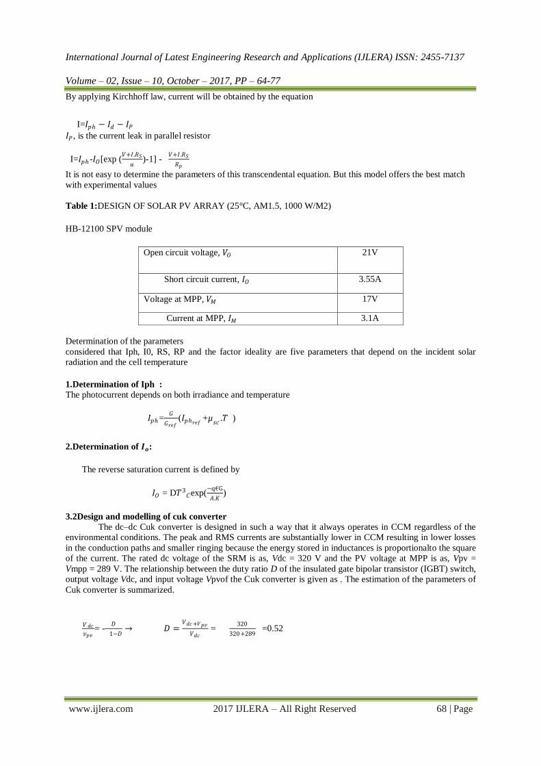
By applying Kirchhoff law, current will be obtained by the equation
I=𝐼𝑝ℎ − 𝐼𝑑 − 𝐼𝑃
𝐼𝑃 , is the current leak in parallel resistor
I=𝐼𝑝ℎ -𝐼𝑂[exp (𝑉+𝐼.𝑅𝑆
𝑎)-1] -
𝑉+𝐼.𝑅𝑆
𝑅𝑝
It is not easy to determine the parameters of this transcendental equation. But this model offers the best match
with experimental values
Table 1:DESIGN OF SOLAR PV ARRAY (25°C, AM1.5, 1000 W/M2)
HB-12100 SPV module
Open circuit voltage, 𝑉𝑂 21V
Short circuit current, 𝐼𝑂 3.55A
Voltage at MPP, 𝑉𝑀 17V
Current at MPP, 𝐼𝑀 3.1A
Determination of the parameters
considered that Iph, I0, RS, RP and the factor ideality are five parameters that depend on the incident solar
radiation and the cell temperature
1.Determination of Iph :
The photocurrent depends on both irradiance and temperature
𝐼𝑝ℎ=𝐺
𝐺𝑟𝑒𝑓(𝐼𝑝ℎ𝑟𝑒𝑓 +µ
𝑠𝑐.𝑇 )
2.Determination of 𝑰𝒐:
The reverse saturation current is defined by
𝐼𝑂 = D𝑇3𝐶exp(
−q€G
𝐴.𝐾)
3.2Design and modelling of cuk converter
The dc–dc Cuk converter is designed in such a way that it always operates in CCM regardless of the
environmental conditions. The peak and RMS currents are substantially lower in CCM resulting in lower losses
in the conduction paths and smaller ringing because the energy stored in inductances is proportionalto the square
of the current. The rated dc voltage of the SRM is as, Vdc = 320 V and the PV voltage at MPP is as, Vpv =
Vmpp = 289 V. The relationship between the duty ratio D of the insulated gate bipolar transistor (IGBT) switch,
output voltage Vdc, and input voltage Vpvof the Cuk converter is given as . The estimation of the parameters of
Cuk converter is summarized.
𝑉 𝑑𝑐
𝑣𝑝𝑣= -
𝐷
1−𝐷→ 𝐷 =
𝑉𝑑𝑐 +𝑉𝑝𝑣
𝑉𝑑𝑐 =
320
320+289 =0.52

International Journal of Latest Engineering Research and Applications (IJLERA) ISSN: 2455-7137
Volume – 02, Issue – 10, October – 2017, PP – 64-77
www.ijlera.com 2017 IJLERA – All Right Reserved 69 | Page
The selected values for dc link capacitors are estimated as
C1 = C2 = 𝐼(30 −𝛼)
2𝜔Δ𝑉dc
where I = DC link current, ω = rated angular speed of SRM, α = conduction angle, ΔVdc = amount of
permitted ripple in the voltage across dc link capacitors C1 and C2 , i.e., 1.5% of Vdc. Considering Pin as 900
W, Vdcas 320 V, f as 50 Hz and ΔVc1 = ΔVc2 as 1.5% of Vc1,2,the obtained value of “I” is 2.34 A and the
obtained value of C1 = C2 is 2441 μF; hence, C1 and C2 are selected as 2500 μF.
3.3. Design and Modeling of SRM
The equivalent circuit of SRM is modeled as a currentcontrolled voltage source as shown in Fig. In this
equivalent circuit, e(t) is the e.m.f. of the SRM. Due to the saliency on rotor and stator side, SRM has
nonsinusoidal current and flux across all four windings against the pulse voltage supply. The modeling is carried out on the supposition that the magnetic coupling between two consecutive windings of SRM is
negligible and its phase inductance profile has the nonlinear shape [17], [18]. Fig. 5 shows the developed
simulink model for 750W, 8/6 pole, 1500 r/min SRM. ITBL and TTBL are the current and torque lookup table
obtained from experimental data. The expression obtained after applying KVL in conducting phase of SRM is as
Fig 3.1.Equivalent circuit of SRM.
V=Ri+𝑑𝜓
𝑑𝑡 = Ri +
𝑑(𝐿𝑖)
𝑑𝑡
=Ri+L𝑑𝑖
𝑑𝑡 +i
𝑑𝐿
𝑑𝑡
=Ri+L𝑑𝑖
𝑑𝑡 +i
𝑑𝐿
𝑑𝜃 *
𝑑𝜃
𝑑𝑡 = Ri+L
𝑑𝑖
𝑑𝑡 +i
𝑑𝐿
𝑑𝑡 + ωmi
𝑑𝐿
𝑑𝜃
where “V” is the terminal voltage, iis the current, ψ is the flux-linkage in volt–seconds, R is the phase
resistance, L is the phase inductance, θ is the rotor position, and ωmis the angular velocity in rad/s. The
last term is sometimes interpreted as a “back-EMF” as follows:
e=ωm .i𝑑𝐿
𝑑𝜃
The instantaneous electrical power V ×i as follows
Vi=R𝑖2+ Li 𝑑𝑖
𝑑𝑡 +ω𝑖2 𝑑𝐿
𝑑𝜃
The rate of change of magnetic stored energy at any instant is given as follows:
𝑑𝑖
𝑑𝑡
1
2𝐿𝑖2 =
1
2𝑖2 𝑑𝐿
𝑑𝑡 + 𝐿𝑖
𝑑𝑖
𝑑𝑡=
1
2𝑖2 ωm
𝑑𝐿
𝑑𝜃+Li
𝑑𝑖
𝑑𝑡
The mechanical power conversion is as follows
P=Tωs
the developed torque is as follows

International Journal of Latest Engineering Research and Applications (IJLERA) ISSN: 2455-7137
Volume – 02, Issue – 10, October – 2017, PP – 64-77
www.ijlera.com 2017 IJLERA – All Right Reserved 70 | Page
T=0.5𝑖2 𝑑𝐿
𝑑𝜃
Fig 3.3.2Developed simulink model of SRM .
III. OPERATION AND CONTROL OF PROPOSED SYSTEM In the proposed system, maximum power of the SPV array is tracked using InC MPPT technique and
the mid-point converter feeding current pulses to the SRM is operated through the electronic commutation.
These controllers at the various stages are discussed in brief in following subsections .
4.1MPPT Control
The location of MPP in the I–V characteristics of SPV array is not predicted in advance and always
varies dynamically with insolation levels and environmental conditions The governing equations which explain
the operating principle of InC method are as
𝑣𝑝𝑣𝑟𝑒𝑓 (k) = 𝑣𝑝𝑣𝑟𝑒𝑓 (k+1) + step, if Δ𝐼
Δ𝑉⊱ -
𝐼𝑝𝑣
𝑣𝑝𝑣
𝑣𝑝𝑣𝑟𝑒𝑓 (k) = 𝑣𝑝𝑣𝑟𝑒𝑓 (k-1) -step, if Δ𝐼
Δ𝑉⊰ -
𝐼𝑝𝑣
𝑣𝑝𝑣
whereΔI &ΔV = change in PV current and voltage in two consecutive samples
The reference voltage of SPV array is checked for upper and lower limits, which are set to 0.7
Vocmax–0.9 Vocmax. In case the Vpvrefis between the limits, it is kept as it is else the Vpvref is saturated to the
nearest limit. The saturation block output is designated as new reference PV voltage (Vpvrefn). The Vpvrefn and
sensed PV voltage are then used to estimate the duty ratio for the Cuk converter. The governing equation for
estimating

International Journal of Latest Engineering Research and Applications (IJLERA) ISSN: 2455-7137
Volume – 02, Issue – 10, October – 2017, PP – 64-77
www.ijlera.com 2017 IJLERA – All Right Reserved 71 | Page
Fig 4.1.1Explanation of InC method and generation of duty cycle for dc–dc converter by InC algorithm.
Diagrammatical explanation of (a) InC method and (b) generation of duty cycle for dc-dc converter.
TABLE 2:ALL POSSIBLE SCENARIO OF INC ALGORITHM
General
Condition
First Point
Happened
Duty Cycle
Next Point
Fixed Solar
Irradiance Level
MPP-1
B
MPP-1
C
A(𝑃𝑝𝑣 ↓, 𝑣𝑝𝑣 ↓)
A(𝑃𝑝𝑣 ↓ 𝑣𝑝𝑣 ↓)
D(𝑃𝑝𝑣 ↓ 𝑣𝑝𝑣 ↑)
D(𝑃𝑝𝑣 ↓ 𝑣𝑝𝑣 ↓)
D+
D+
D-
D-
B
G
C
Below c
Variable Solar
Irradiance
MPP-2
MPP-2
MPP-1
MPP-1
B(𝑃𝑝𝑣 ↓ 𝑣𝑝𝑣 ↑)
C(𝑃𝑝𝑣 ↑ 𝑣𝑝𝑣 ↑)
E(𝑃𝑝𝑣 ↓ 𝑣𝑝𝑣 ↓)
F(𝑃𝑝𝑣 ↓ 𝑣𝑝𝑣 ↑)
D-
D+
D+
D+
G
MPP-1
H
Below F
Cuk converter duty ratio is as follows
D(k) = 1-𝑣𝑝𝑣
𝑣𝑝𝑣+𝑣𝑝𝑣𝑟𝑒𝑓
This reference duty ratio is compared with saw-tooth waveform to generate switching logic for the switch of the
Cuk converter.
4.2Control of Mid-Point Converter
The complete switching scheme of a mid-point converter is controlled by three parameters: the advance
angle (turn-ON angle), θon, turn-OFF angle, θoff, and value of the effective dc link voltage. The switching
angles are defined for each phase based on the rotor position estimation provided by a position Hall
sensorslocated on the stator of SRM . A mid-point converter injects unipolar current pulses at desired rotor
positions to SRM drive. It also controls the magnitude of current for efficient operation of the motor drive and
IGBT switches .The voltage equation at starting is as follows
1
2𝑉𝑑𝑐 =L (
𝑑𝑖
𝑑𝑡) = L (
𝑑𝑖
𝑑𝜃) (
𝑑𝜃
𝑑𝑡)
L ω (𝑑𝑖
𝑑𝜃)as ω =(
𝑑𝜃
𝑑𝑡)

International Journal of Latest Engineering Research and Applications (IJLERA) ISSN: 2455-7137
Volume – 02, Issue – 10, October – 2017, PP – 64-77
www.ijlera.com 2017 IJLERA – All Right Reserved 72 | Page
Phase voltage
Phase current
Device status
VA = Vdc/2
i1⊱0
T1-ON,D1-OFF,D2-OFF
VA = - Vdc/2
-
T1-OFF ,D1-ON, D2-ON
VA = 0
i1⊰0
T1-OFF,D1-OFF,D2-OFF
4.3Proportional-Integral (PI) controller
The combination of proportional and integral terms is important to increase the speed of the response
and also to eliminate the steady state error
The controller output is given by
The Proportional-Integral (PI) algorithm computes and transmits a controller outputsignal every sample
time, T, to the final control element. The computed output from the PI algorithm is influenced by the controller
tuning parameters and the controller error (Δ).Integral action enables PI controllers to eliminate offset, a major
weakness of a P-only controller. Its function is to integrate or continually sum thecontroller error
The proportional term of the PI controller adds or subtracts based on the size of controller error. As
error grows or shrinks, the amount added grows or shrinks immediately or proportionately. While the
proportional term considers the current size of error only at the time of the controller calculation, the integral
term considers the history of the error, or how long and how far the measured process variable has been from the
set point over time. Thus the integral action eliminates offset. It continually resetsthe bias value of controller
toeliminate offset as operating level changes. Thus the PI controller eliminates offset error and increases the
speed of the response.
Table 3:Comparison of different types of conventional controllers

International Journal of Latest Engineering Research and Applications (IJLERA) ISSN: 2455-7137
Volume – 02, Issue – 10, October – 2017, PP – 64-77
www.ijlera.com 2017 IJLERA – All Right Reserved 73 | Page
In this case, the flux and constant and variable speed from the output is given as input to the PI
controller through sum and output of PI controller is given as gate signal to each converter whichcontrols the
phases of SRM.The following values are given for PI controller. kp=0.00188
KI=0.299 These values for Kp and Ki are found using trial and error method. PI controller is more suitable
during steady state and provides robustness to load disturbance.
Fig 4.3.1: SIMULATION DIAGRAMClosed loop pi control for switched reluctance motor drive
IV. RESULT DISCUSSION
The output obtained for four phase SRM using PI controller is shown below. Singleconverter is used
for each phase and hence totally four converters for four phases. Thus voltage, current and flux for four phases
is obtained. Speed and torque waveform for motor is shown in last two graphs. Speed is controlled by varying the turn on and turn off angle which is given to converter through the PI
controller. The tolerance of SRM is small when comparedwith other motors.
Fig 5.1:solar power waveforme

International Journal of Latest Engineering Research and Applications (IJLERA) ISSN: 2455-7137
Volume – 02, Issue – 10, October – 2017, PP – 64-77
www.ijlera.com 2017 IJLERA – All Right Reserved 74 | Page
Fig 5.1.1Performance of SPV array.
Fig 5.2:performance ofclosedloop pi control of variable speed SRM Drive(2000 rpm -3000 rpm)
0 0.05 0.1 0.15 0.2 0.25 0.3 0.35 0.4 0.45 0.5999
1000
1001
Pow
er
0 0.05 0.1 0.15 0.2 0.25 0.3 0.35 0.4 0.45 0.50
200
400
Vpv
0 0.05 0.1 0.15 0.2 0.25 0.3 0.35 0.4 0.45 0.50
2
4
Ipv
0 0.05 0.1 0.15 0.2 0.25 0.3 0.35 0.4 0.45 0.50
1000
2000
Time(sec)
Pow
er
0 0.05 0.1 0.15 0.2 0.25 0.3 0.35 0.4 0.45 0.5-200
0
200
400
Cur
rent
0 0.05 0.1 0.15 0.2 0.25 0.3 0.35 0.4 0.45 0.5-200
0
200
400
Toeq
ue
0 0.05 0.1 0.15 0.2 0.25 0.3 0.35 0.4 0.45 0.5-2000
0
2000
4000
Time(sec)
Spe
ed

International Journal of Latest Engineering Research and Applications (IJLERA) ISSN: 2455-7137
Volume – 02, Issue – 10, October – 2017, PP – 64-77
www.ijlera.com 2017 IJLERA – All Right Reserved 75 | Page
Fig 5.3:performance of closedloop pi control of constant speed (2000) SRM Drive
Fig 5.4:Cuk converter parameters response.
0 0.05 0.1 0.15 0.2 0.25 0.3 0.35 0.4 0.45 0.5-200
0
200
400
Curr
ent(
A)
0 0.05 0.1 0.15 0.2 0.25 0.3 0.35 0.4 0.45 0.5-200
0
200
400
Te
0 0.05 0.1 0.15 0.2 0.25 0.3 0.35 0.4 0.45 0.5-2000
0
2000
4000
Time(sec)
Speed(r
pm
)
0 0.001 0.002 0.003 0.004 0.005 0.006 0.007 0.008 0.009 0.010
5
10
ili(A
)
0 0.005 0.01 0.015 0.02 0.025 0.03 0.035 0.04 0.045 0.05300
400
500
Vcm
(V)
0 0.001 0.002 0.003 0.004 0.005 0.006 0.007 0.008 0.009 0.010
5
10
ilo(A
)
0 0.05 0.1 0.15 0.2 0.25 0.3 0.35 0.4 0.45 0.590
100
110
Vc1
0 0.05 0.1 0.15 0.2 0.25 0.3 0.35 0.4 0.45 0.590
100
110
Time(sec)
Vc2

International Journal of Latest Engineering Research and Applications (IJLERA) ISSN: 2455-7137
Volume – 02, Issue – 10, October – 2017, PP – 64-77
www.ijlera.com 2017 IJLERA – All Right Reserved 76 | Page
Fig: 5.5 Performance of SPV array and variation of duty cycle for switch of Cuk converter during varying
insolation levels
VI.CONCLUSION In this paper, the speed of foure phase SRM is controlled using PI controller.It is clear that the offset
error is eliminated and the speed of the response is increased. this theree phase motor has more advantages
such as the reduction in torque ripple with increase in the number of phases and faster response. In 8/6 SRM the
torque and speed control performance will be more when compared to other controllers.The CCM operation of
Cuk converter has also boosted the efficiency of proposed water pumping system by reducing voltage and
current stresses on devices of Cuk converter and increasing power output ofCuk converter by lowering the
ringing effect of system.Closed loop pi controller has the advantages of controlling the constant speed and
variable speed of SRM drive.
APPENDIX:
A. SRM Specification :
750 W, 8/6 pole, Four phase, 1500 r/min, dc link voltage =320 V.
B. Selected Parameters of Solar PV Array
Open circuit voltage, Voc = 21 V; Short circuit current, Isc = 3.55 A; Maximum power, Pmp =
900W;Voltage at MPP, Vmp = 289 V; Current at MPP, Imp = 3.1 A; Numbers of modules connected in series,
ns = 17; Numbers of modules connected in parallel, np = 1.
C. Parameter Selection for Design of Cuk Converter
Switching frequency, fsw = 20 kHz; Input inductor, Li = 6.25 mH; Output inductor, Lo = 6.87 mH; Energy
transfer capacitor,Cm = 3μF; dc link capacitors, C1 = C2 = 2500 μF.
D. PI controller
Reference speeds 2000 and3000
0 0.2 0.4 0.6 0.8 1 1.2 1.4500
600
700
800
900
1000
Time(sec)
pow
er(
W)
0 0.2 0.4 0.6 0.8 1 1.2 1.40
100
200
300
Time(sec)
Vpv(V
)

International Journal of Latest Engineering Research and Applications (IJLERA) ISSN: 2455-7137
Volume – 02, Issue – 10, October – 2017, PP – 64-77
www.ijlera.com 2017 IJLERA – All Right Reserved 77 | Page
REFERENCES [1]. B.N. SINGH, B. SINGH, B.P. SINGH, A. CHANDRA AND K. AL-HADDAD, “OPTIMIZED PERFORMANCE OF
SOLAR POWERED VARIABLE SPEED INDUCTION MOTOR DRIVE,” PROC. OF THE INTERNATIONAL CONFERENCE
ON POWER ELECTRONICS, DRIVES AND ENERGY SYSTEMS FOR INDUSTRIAL GROWTH (PEDES’96) HELD AT
NEW DELHI, 1996 PP, 58-66.
[2]. K.Y.Lu, P.O.Rasmussen, S.J. Watkins and F. Blaabjerg, “A New Low-Cost Hybrid Switched Reluctance
Motor for Adjustable-Speed Pump Applications,‟‟ Proc. of IEEE 41st IAS Annual Meeting, held at 8-12
Oct.2006, pp.849-854.
[3]. S. Belliwali, A. Chakravarti and A.B. Raju, “Mathematical modelling and simulation of directly coupled
PV water pumpingsystem employing Switched Reluctance Motor,’’ Proc. of IEEE PES Innovative Smart
Grid Technologies - India (ISGT India), 1-3 Dec.2011, pp.no.386-390.
[4]. Mahesh Krishnamurthy, Chris S. Edrington and BabakFahimi, “Prediction of Rotor Position at Standstill
and Rotating Shaft Conditions in Switched Reluctance Machines,” IEEE Transactions on Power
Electronics, vol. 21, no. 1, pp. 225-233, January 2006.
[5]. Kim Jaehyuck and R.Krishnan, “Novel Two-Switch-Based Switched Reluctance Motor Drive for Low-
Cost High-Volume Applications,” IEEE Transactions on Industry Applications, vol.45, pp.1241-1248,
July-Aug. 2009.
[6]. B. Singh and A.K. Mishra, “Canonical switching cell converter fed SRM drive for SPV array based water
pumping,” 2nd InternationalConference on Computing for Sustainable Global Development
(INDIACom), 11-13 March 2015, pp.932-937.
[7]. D.Sera, L. Mathe, T.Kerekes, S.V. Spataru and R.Teodorescu, “On the Perturb-and-Observe and
Incremental Conductance MPPT Methods for PV Systems,” IEEE Journal of Photovoltaics, vol.3, no.3,
pp.1070-1078, July 2013.
[8]. R. Krishnan,Switched Reluctance Motor Drives: Modeling, Simulation, Analysis, Design and
Applications. Boca Raton, FL, USA: CRC Press,2001
[9]. T. J. E. Miller,Switched Reluctance Motor and Their Control. Madison, WI, USA: Magna Physics
Publishing, 1993.
[10]. B. K. BOSE, T. J. E. Bose, P. M. Szczesny, and W. H. Bicknell, “Microomputer control of
switchedreluctance motor,” IEEE Trans. Ind. Appl., vol. IA-22, no. 4, pp. 708–714, Jul./Aug., 1986.
[11]. V. Bist and B. Singh, “PFC Cuk converter-fed BLDC motor drive,” IEEE Trans. Power Electron., vol.
30, no. 2, pp. 871–887, Feb. 2015.