closed loop operation of step-up resonant converterconverter topologies based on resonant...
TRANSCRIPT
International Research Journal of Engineering and Technology (IRJET) e-ISSN: 2395 -0056
Volume: 04 Issue: 04 | Apr -2017 www.irjet.net p-ISSN: 2395-0072
© 2017, IRJET | Impact Factor value: 5.181 | ISO 9001:2008 Certified Journal | Page 1
Closed Loop Operation of Step-up Resonant Converter
Dinto Mathew1, Susmitha K Babu2, Dawtie Grace Joseph3 ,Athulya M.S4
1Asst.Professor, Dept. of Electrical and Electronics Engineering, Mar Athanasius College of Engineering, Kothamangalam, Kerala
2,3,4 Students, Dept. of Electrical and Electronics Engineering, Mar Athanasius College of Engineering, Kothamangalam, Kerala
---------------------------------------------------------------------***---------------------------------------------------------------------
Abstract - The increased use of the fossil fuels such as the oil, the coal and the gas, result in serious greenhouse effect and pollute the atmosphere, which has great effect on the world. Meanwhile, there is a big contradiction between the fossil fuels supply and the global energy demand, which leads to a high oil price in the international market recently. The energy shortage and the atmosphere pollution have been the major limitations for the human development. Photovoltaic (PV) sources are one of the significant players in the worlds energy portfolio and will become the biggest contributions to the electricity generation among all renewable energy candidates. Because it is truly a clean, emission free renewable electrical generation technology with high reliability. A resonant dc-dc converter topology is used for the first stage of a two-stage converter to link a renewable energy source to a utility grid. For reliable input to a grid the inverter needs a stiff input dc voltage. To minimize switching loss and avoid switching over voltages a resonant converter is used. To gain the necessary dc voltage at the inverter input, it is necessary to use a dc/dc step-up converter. Connected to the output of the converter is a series combination of the inductor and a capacitor such that the capacitor resonates with the inductor at the switching frequency. The output from resonant tank is rectified and filtered for input to the inverter. Results from simulation tests confirm the current’s resonant pattern. Yet further results are shown of the converter’s performance at different loadings to confirm the zero-current switching effects. It is concluded that this converter topology provides a reliable basis for the application under consideration. Key Words: Resonant converter, voltage step-up, renewable energy, soft switching, voltage stress
1.INTRODUCTION
Our planet is facing serious energy crisis due to the escalating energy demand which could not be satisfied with the supply available. Coal, petroleum and even hydroelectric power are inadequately available at present. Now it is high time that we take necessary precautions to handle this situation. Recently researches are being carried out on renewable energy systems. The development of renewable energy sources is crucial to relieve the pressures of exhaustion of the fossil fuel and environmental pollution. At present, most of the renewable energy sources are
utilized with the form of AC power. The generation equipments of the renewable energy sources and energy storage devices usually contain DC conversion stages and the produced electrical energy is delivered to the power grid through DC/AC stages, resulting in additional energy loss. Moreover, the common problem of the renewable energy sources, such as wind and solar, is the large variations of output power, and the connection of large scale of the renewable sources to the power grid is a huge challenge for the traditional electrical equipment, grid structure and operation. Among the many photovoltaic system seems to be attractive due to its inherent characteristics such as abundance in availability, cost free safe resource and its ecofriendly nature. The only disadvantage of the PV system is that the output voltage being very low. But to meet the required output according to bus voltage specifications the role of power electronics comes into play. DC grid is another solution to the aforementioned issues such as the energy losses during the conversion stages and is an emerging and promising approach which has been drawn much attention recently impact on conventional plant.
For the application where galvanic isolation is not mandatory, the use of a transformer would only increase the cost, volume and losses, especially for high-power high-voltage applications. Several non-isolated topologies for high-power high-voltage applications have recently been proposed and studied in the literature. A Boost converter is adapted by the researchers of Converteam company [1] to transmit energy from 50kV to 200kV. To obtain the higher voltage-gain, Enjeti et al[2] proposed a multiple-module structure, which consists of a Boost converter and a Buck/Boost converter connected in input parallel output-series. The output power and voltage are shared by the two converters and the voltage and current ratings of switches and diodes are correspondingly reduced. However, the efficiency of Boost or Buck/Boost converter is relatively low due to the hard switching of the active
International Research Journal of Engineering and Technology (IRJET) e-ISSN: 2395 -0056
Volume: 04 Issue: 04 | Apr -2017 www.irjet.net p-ISSN: 2395-0072
© 2017, IRJET | Impact Factor value: 5.181 | ISO 9001:2008 Certified Journal | Page 1257
switch and the large reverse recovery loss of the diode. The soft-switching technology is critical to improve the conversion efficiency, especially for high-voltage applications. Recently, several soft-switching topologies for high-power high-voltage applications have been proposed. In [3,4], the converter topologies based on resonant switched-capacitor (RSC) are proposed with reduced switching loss and modular structure. The shortage of the RSC based converter is the poor voltage regulation and the requirement of a large number of capacitors. Novel type of resonant step-up converter [5-7] with potentially soft-switching operation utilizes thyristors as switches and does not suffer from excessive switch stresses and reverse recovery problems, moreover, a large voltage-gain is easily to be obtained. Similarly, the main feature of a resonant transformer less modular DC-DC converter [8] is that the unequal voltage stress on semiconductors of thyristor valve is avoided with the use of active switching network, which is composed of an ac capacitor and four identical active switches. Thyristors have large voltage and current ratings; however, the use of thyristor limits the switching frequency of the converter, resulting in bulky passive components and slow dynamic response [9]. Moreover, the resonant inductors of the converters are unidirectional magnetized in [5-8] leading to lower utilization of the magnetic core, which means that a great volume of core is required. Hence resonant step-up DC-DC converter is used, which not only can realize soft switching for main switches and diodes and large voltage-gain, but also has relatively lower equivalent voltage stress of the semiconductor devices and bidirectional magnetized resonant inductor.
2. LITERATURE SURVEY Furkan Dincer[10] analyzed photovoltaic energy power systems as the most dominant source among renewable energy technologies. Among various solar energy technologies of sustainable energy sources, photovoltaic (PV) appears quite attractive for electricity generation because it is noiseless, no carbon dioxide emission during operation, scale flexibility and rather simple operation and maintenance. L. Bird et. al [11] compared wind and solar generation sources and concluded that much of the variation in solar energy output during the course of the day and the year can be analyzed easily. But the uncertainty and variability solar generation can pose challenges for grid operators. Variability in generation from sources can require additional actions to balance the system. Greater
flexibility in the system may be needed to accommodate supply-side variability and the relationship to generation levels and loads. Another challenge occurs when wind or solar generation is available during low load levels. CIGRE B4-52 Working Group [12] proposed DC grid for transmission of energy from renewable energy resources, as the connection of large scale renewable sources to the power grid is a huge challenge for the traditional electrical equipment, grid structure and operation. Also, the generation equipment of the renewable energy sources and energy storage devices usually contain DC conversion stages and the produced electrical energy is delivered to the power grid through DC/AC stages, resulting in additional energy loss. Recently, several soft-switching topologies for high-power high-voltage applications have been proposed. W. Chen, A. Huang, C. Li, et. al [3,4] proposed the converter topologies based on resonant switched-capacitor (RSC) with reduced switching loss and modular structure. The shortage of the RSC based converter is the poor voltage regulation and the requirement of a large number of capacitors. Jovcic et. al proposed a novel type of resonant step-up converter with potentially soft-switching operation, Furkan Dincer[10] analyzed photovoltaic energy power systems as the most dominant source among renewable energy technologies. Among various solar energy technologies of sustainable energy sources, photovoltaic (PV) appears quite attractive for electricity generation because it is noiseless, no carbon dioxide emission during operation, scale flexibility and rather simple operation and maintenance. L. Bird et. al [11] compared wind and solar generation sources and concluded that much of the variation in solar energy output during the course of the day and the year can be analyzed easily. But the uncertainty and variability solar generation can pose challenges for grid operators. Variability in generation from sources can require additional actions to balance the system. Greater flexibility in the system may be needed to accommodate supply-side variability and the relationship to generation levels and loads. Another challenge occurs when wind or solar generation is available during low load levels. CIGRE B4-52 Working Group [12] proposed DC grid for transmission of energy from renewable energy resources, as the connection of large scale renewable sources to the power grid is a huge challenge for the traditional electrical equipment, grid structure and
International Research Journal of Engineering and Technology (IRJET) e-ISSN: 2395 -0056
Volume: 04 Issue: 04 | Apr -2017 www.irjet.net p-ISSN: 2395-0072
© 2017, IRJET | Impact Factor value: 5.181 | ISO 9001:2008 Certified Journal | Page 1258
operation. Also, the generation equipment of the renewable energy sources and energy storage devices usually contain DC conversion stages and the produced electrical energy is delivered to the power grid through DC/AC stages, resulting in additional energy loss. Recently, several soft-switching topologies for high-power high-voltage applications have been proposed. W. Chen, A. Huang, C. Li, et. al[3,4] proposed the converter topologies based on resonant switched-capacitor (RSC) with reduced switching loss and modular structure. The shortage of the RSC based converter is the poor voltage regulation and the requirement of a large number of capacitors. Jovcic et. al proposed a novel type of resonant step-up converter with potentially soft-switching operation, which utilizes thyristors as switches and does not suffer from excessive switch stresses and reverse recovery problems, moreover, a large voltage-gain is easily to be obtained [6-8]. A. A. Hagar and P. W. Lehn [9] proposed a new family of resonant transformerless modular DC-DC converters and the main feature of the proposed converters is that the unequal voltage stress on semiconductors of thyristor valve is avoided with the use of active switching network, which is composed of an ac capacitor and four identical active switches. Thyristors have large voltage and current ratings; however, the use of thyristor limits the switching frequency of the converter, resulting in bulky passive components and slow dynamic response [10]. Moreover, the resonant inductors of the converters are unidirectional magnetized in [6-9], leading to lower utilization of the magnetic core, which means that a great volume of core is required. Wu Chen et.al [13] proposed a novel resonant step-up DC-DC converter, which not only can realize soft switching for main switches and diodes and large voltage-gain, but also has relatively lower equivalent voltage stress of the semiconductor devices and bidirectional magnetized resonant inductor. From the above reviews, it is promising to transmit electrical energy from renewable energy resources especially from solar PV to DC grid using LC parallel resonant converter.
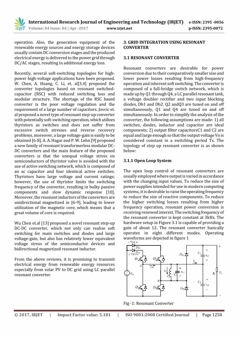
3. GRID INTEGRATION USING RESONANT CONVERTER 3.1 RESONANT CONVERTER Resonant converters are desirable for power conversion due to their comparatively smaller size and lower power losses resulting from high-frequency operation and inherent soft switching. The converter is composed of a full-bridge switch network, which is made up by Q1 through Q4, a LC parallel resonant tank, a voltage doubler rectifier and two input blocking diodes, Db1 and Db2. Q2 andQ3 are tuned on and off simultaneously, Q1 and Q4 are tuned on and off simultaneously. In order to simplify the analysis of the converter, the following assumptions are made: 1) all switches, diodes, inductor and capacitor are ideal components; 2) output filter capacitorsC1 and C2 are equal and large enough so that the output voltage Vo is considered constant in a switching period Ts. The topology of step up resonant converter is as shown below:
3.1.1 Open Loop System The open loop control of resonant converters are usually employed where output is varied in accordance with the changing input values. To reduce the size of power supplies intended for use in modern computing systems, it is desirable to raise the operating frequency to reduce the size of reactive components. To reduce the higher switching losses resulting from higher frequency operation, resonant power conversion is receiving renewed interest. The switching frequency of the resonant converter is kept constant at 3kHz. The hardware setup in Figure 3.1 is capable of providing a gain of about 12. The resonant converter basically operates in eight different modes. Operating waveforms are depicted in figure 1
Fig -1: Resonant Converter
International Research Journal of Engineering and Technology (IRJET) e-ISSN: 2395 -0056
Volume: 04 Issue: 04 | Apr -2017 www.irjet.net p-ISSN: 2395-0072
© 2017, IRJET | Impact Factor value: 5.181 | ISO 9001:2008 Certified Journal | Page 1259
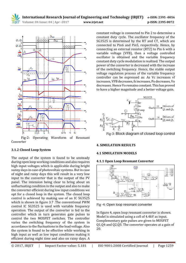
Fig-2: Operating Waveform of Resonant Converter 3.1.2 Closed Loop System The output of the system is found to be unsteady during open loop working conditions and also requires high input voltages which is applicable during bright sunny days in case of photovoltaic systems. But in case of night and rainy days this will result in a very low input to the converter that is the output of the PV panel. The intension being clear to bring about an unfluctuating condition in the output and also to make the converter efficient during low input conditions we opt for a closed loop in the system. The closed loop control is achieved by making use of an IC SG3525 which is shown in figure 3.7 .The conventional PWM control IC SG3525 is used with variable frequency operation. The output of the converter is fed to the controller which in turn generates gate pulses to control the two MOSFET switches. The controller varies the switching frequency of the system in accordance to the fluctuations in the load voltage. Also the system is found to be effective while working in high input as well as low input conditions making it efficient during night time and also on rainy days. A
constant voltage is connected to Pin 2 to determine a constant duty cycle. The oscillator frequency of the SG3525 is determined by the RT and CT, which are connected to Pin6 and Pin5, respectively. Hence, by connecting an external resistor (RT2) to Pin 6 with a variable voltage (VFB), then a voltage controlled oscillator is obtained and the variable frequency constant duty cycle modulation is realized. The output power of the converter is decreased with the increase of the switching frequency. Hence, the stable output voltage regulation process of the variable frequency controller can be expressed as: As Vc increases vf increases, VFB decreases, fs increases, Po decreases, Vo decreases. Hence Vo remains constant. This has proved to have a higher magnitude and a better voltage gain.
Fig-3: Block diagram of closed loop control
4. SIMULATION RESULTS 4.1 SIMULATION MODELS 4.1.1 Open Loop Resonant Converter
Fig -4: Open loop resonant converter In figure 4, open loop resonant converter is shown. Model is simulated using a cell of 4.4kV as input. Complementary gate pulses are given to MOSFET Q1,Q4 and Q2,Q3. The converter operates at a gain of 20.
International Research Journal of Engineering and Technology (IRJET) e-ISSN: 2395 -0056
Volume: 04 Issue: 04 | Apr -2017 www.irjet.net p-ISSN: 2395-0072
© 2017, IRJET | Impact Factor value: 5.181 | ISO 9001:2008 Certified Journal | Page 1260
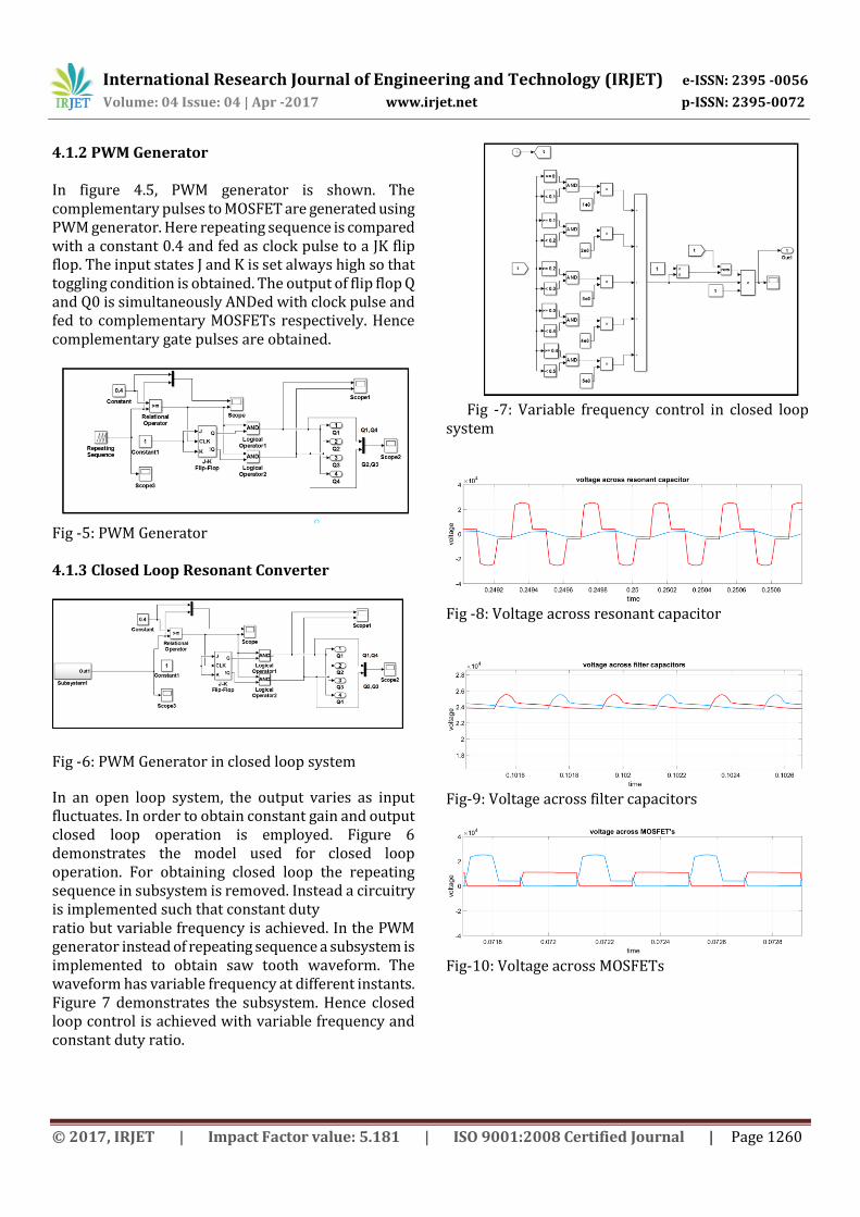
4.1.2 PWM Generator In figure 4.5, PWM generator is shown. The complementary pulses to MOSFET are generated using PWM generator. Here repeating sequence is compared with a constant 0.4 and fed as clock pulse to a JK flip flop. The input states J and K is set always high so that toggling condition is obtained. The output of flip flop Q and Q0 is simultaneously ANDed with clock pulse and fed to complementary MOSFETs respectively. Hence complementary gate pulses are obtained.
Fig -5: PWM Generator 4.1.3 Closed Loop Resonant Converter
Fig -6: PWM Generator in closed loop system
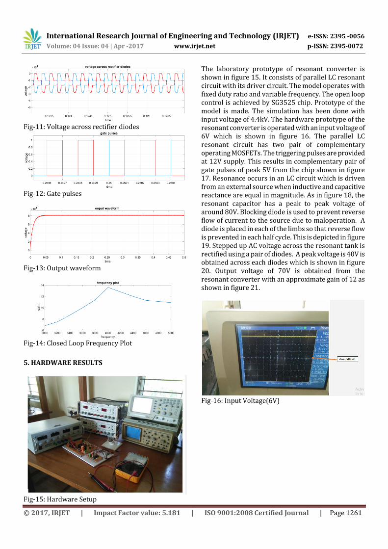
In an open loop system, the output varies as input fluctuates. In order to obtain constant gain and output closed loop operation is employed. Figure 6 demonstrates the model used for closed loop operation. For obtaining closed loop the repeating sequence in subsystem is removed. Instead a circuitry is implemented such that constant duty ratio but variable frequency is achieved. In the PWM generator instead of repeating sequence a subsystem is implemented to obtain saw tooth waveform. The waveform has variable frequency at different instants. Figure 7 demonstrates the subsystem. Hence closed loop control is achieved with variable frequency and constant duty ratio.
Fig -7: Variable frequency control in closed loop system
Fig -8: Voltage across resonant capacitor
Fig-9: Voltage across filter capacitors
Fig-10: Voltage across MOSFETs
International Research Journal of Engineering and Technology (IRJET) e-ISSN: 2395 -0056
Volume: 04 Issue: 04 | Apr -2017 www.irjet.net p-ISSN: 2395-0072
© 2017, IRJET | Impact Factor value: 5.181 | ISO 9001:2008 Certified Journal | Page 1261
Fig-11: Voltage across rectifier diodes
Fig-12: Gate pulses
Fig-13: Output waveform
Fig-14: Closed Loop Frequency Plot
5. HARDWARE RESULTS
Fig-15: Hardware Setup
The laboratory prototype of resonant converter is shown in figure 15. It consists of parallel LC resonant circuit with its driver circuit. The model operates with fixed duty ratio and variable frequency. The open loop control is achieved by SG3525 chip. Prototype of the model is made. The simulation has been done with input voltage of 4.4kV. The hardware prototype of the resonant converter is operated with an input voltage of 6V which is shown in figure 16. The parallel LC resonant circuit has two pair of complementary operating MOSFETs. The triggering pulses are provided at 12V supply. This results in complementary pair of gate pulses of peak 5V from the chip shown in figure 17. Resonance occurs in an LC circuit which is driven from an external source when inductive and capacitive reactance are equal in magnitude. As in figure 18, the resonant capacitor has a peak to peak voltage of around 80V. Blocking diode is used to prevent reverse flow of current to the source due to maloperation. A diode is placed in each of the limbs so that reverse flow is prevented in each half cycle. This is depicted in figure 19. Stepped up AC voltage across the resonant tank is rectified using a pair of diodes. A peak voltage is 40V is obtained across each diodes which is shown in figure 20. Output voltage of 70V is obtained from the resonant converter with an approximate gain of 12 as shown in figure 21.
Fig-16: Input Voltage(6V)
International Research Journal of Engineering and Technology (IRJET) e-ISSN: 2395 -0056
Volume: 04 Issue: 04 | Apr -2017 www.irjet.net p-ISSN: 2395-0072
© 2017, IRJET | Impact Factor value: 5.181 | ISO 9001:2008 Certified Journal | Page 1262
Fig-17: Complementary Gate Pulses To The MOSFETs
Fig-18: Voltage Across Resonant Capacitor
Fig-19: Voltage Across Db1
Fig-20: Voltage Across DR1
Fig-21: Output Voltage 3. CONCLUSIONS Conventional sources of power will not be able to address the energy crisis of tomorrow. Moreover, the environmental price paid for conventional energy sources cannot be justified by a civilized society. In this context non-conventional source of power is the only solution among which solar power is the most promising one. Though solar power is being harnessed for a few years now the technology is in its infancy. Researches and theoretical advancement in this area is a small drop in a mighty ocean that will secure pollution free, sustainable energy in future. Considering the above facts, the closed loop voltage mode control of a high step up converter was designed, simulated, hardware implemented and tested. The output voltage obtained was found to be steady without fluctuations. This resonant DC-DC converter can achieve very high step-up voltage gain and it is suitable for high-power high-voltage applications. The converter utilizes the resonant inductor to deliver power by charging from the input and discharging to the output. The resonant capacitor is employed to achieve zero-voltage turn-on and turn-o_ for the active switches and ZCS for the rectifier
International Research Journal of Engineering and Technology (IRJET) e-ISSN: 2395 -0056
Volume: 04 Issue: 04 | Apr -2017 www.irjet.net p-ISSN: 2395-0072
© 2017, IRJET | Impact Factor value: 5.181 | ISO 9001:2008 Certified Journal | Page 1263
diodes. The analysis demonstrates that the converter can operate at any gain value (greater than two) with proper control, however, the parameters of the resonant tank determine the maximum switching frequency, the range of switching frequency and current ratings of active switches and diodes. The converter is controlled by the variable switching frequency. Simulation and experimental results verify the operation principle of the converter and parameters selection of the resonant tank. The study of a high step-up converter has inculcated a confidence that these researches can definitely bring about a revolution in the energy scenario of today.
REFERENCES [1] Zhan, C and Smith, C and Crane, A and Bullock, A and Grieve, D \DC transmission and distribution system for a large offshore wind farm ", AC and DC Power Transmission, 2010. ACDC. 9th IET International Conference, 2010; pp 1-5. [2] N. Dennison, A. Masood, S. Ahmed, et al, \Multiple module high gain high voltage DC-DC transformers for offshore wind energy systems, ", IEEE Trans. Ind. Electron., , vol. 58, no. 5, pp. 1877 1886, 2011. [3] W. Chen, A. Huang, C. Li, et al, \Analysis and comparison of medium voltage high power DC/DC converters for offshore wind energy systems", IEEE Trans. Power Electron.,,vol. 28, no. 4, pp. 20142023,2013. [4] A. Para star, A. Gondomar, M. Jin, and J. Souk, High power solid-state step-up resonant Marx modulator with continuous output current for offshore wind energy systems, in Proc. IEEE ECCE, 2013, pp. 17091716. [5] D. Jovcic, \Step-up dc dc converter for megawatt size applications,", IET Power Electron., vol.2, no. 6, pp. 675685, 2009. [6] D. Jovcic, \Bidirectional, high-power DC transformer,", IEEE Trans. Power Del.,vol. 24, no. 4, pp. 22762283, 2009. [7] J. Robinson, D. Jovcic, and G. Jos, \Analysis and design of an offshore wind farm using a MV DC grid,", IEEE Trans. Power Del., vol. 25, no. 4, pp. 21642173, 2010.
[8] A. A. Hagar and P. W. Lehn, \Comparative evaluation of a new family of transformerless modular DCDC converters for high-power applications", IEEE Trans. Power Delivery,vol. 29, no. 1, pp. 444452, 2014.