closed loop magnetic levitation control of a rotary
TRANSCRIPT

Closed Loop Magnetic Levitation Control
of a Rotary Inductrack System
(CLMLCRIS)
Senior Project Final Report
Students:
Corey West
Austin Collins
Advisors:
Mr. S. Gutschlag
Dr. Y. Lu
Dr. W. Anakwa
Date:
May 16, 2013

1
abstract – There are currently bullet trains that are using magnetic levitation to travel more efficiently for long distances than planes or regular trains. These trains work by inducing a current in the track from an on-board generator in the train. This method of producing levitation is not very energy efficient. A permanent magnet is used to induce a current in the inductrack instead of the generator to improve efficiency. This project is a continuation of a project done last year. There will be an FPGA added to control the system, thereby making it stand-alone. A circuit is designed to control the motor speed by using a pulse-width modulation (PWM) signal generated by an FPGA. The user will input a desired levitation height into the FPGA which will be converted to a velocity from a look-up table. This is the required motor velocity to reach the levitation height set by the user.

2
Table of Contents Background……………………………………………………………………………………………....3
Magnetic Levitation………………………………………………………………………….......3
Halbach Array and Inductrack Theory…………………………………………………………...3
CLMLCRIS Project……………………………………………………………………………………...4
Current Project…………………………………………………………………………………...4
Controller………………………………………………………………………………………...4
Project Objective…………………………………………………………………………………5
Power Electronics………………………………………………………………………………………..6
Analog Circuitry……………………………………………………………………………….....6
Pittman Motor Results……………………………………………………………………………7
FPGA…………………………………………………………………………………………………….8
Rotary Encoder…………………………………………………………………………………...8
Pulse Counter…………………………………………………………………………………….9
Look-Up Tables…………………………………………………………………………………..9
Controller……………………………………………………………………………………….10
Pulse-Width Modulation………………………………………………………………………..12
Conclusion……………………………………………………………………………………………...13
Appendix A……………………………………………………………………………………………..14
Appendix B……………………………………………………………………………………………..15
Appendix C……………………………………………………………………………………………..16

3
Background
Magnetic Levitation Magnetic Levitation has been around since as early as 1984. The purpose of this differentiation from traditional methods was to remove efficiency losses due to friction. There are two currently used methods to achieve magnetic levitation (hereby referred to as “maglev”) for trains. The first is electromagnetic suspension and the other is electrodynamic suspension, but both of these methods demand power to achieve maglev. The method using an inductrack is a newer method that is based on a passive system. Using this method could offer a better form of transportation than the current methods. Dr. Richard Post was responsible for developing the inductrack method, as well as deriving the equations used to understand the system.
Halbach Array and Inductrack Theory A Halbach Array is a group of magnets which are each aligned in a specific pattern to direct all of the magnets’ magnetic fields below the array. Figure 1 displays the alignment as well as the direction of the magnetic fields of the magnets.
Figure 1 Halbach Array Magnetic Fields
The inductrack is a group of inductors designed specifically to interact with the Halbach Array. When the inductrack rotates beneath the Halbach Array, the changing magnetic field induces a magnetic flux around the inductrack, which generates a current and voltage along the inductrack. As the speed of the system increases, the phase lag increases and allows the two magnetic fields generated to align. This process can be seen in Figure 2. The dial represents velocity, which increases in each picture showing how the magnetic poles align and cause the magnetic levitation.
Figure 2 Magnetic Repulsion
4
CLMLCRIS Project
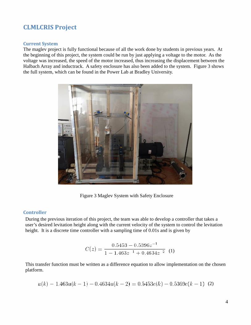
Current System The maglev project is fully functional because of all the work done by students in previous years. At the beginning of this project, the system could be run by just applying a voltage to the motor. As the voltage was increased, the speed of the motor increased, thus increasing the displacement between the Halbach Array and inductrack. A safety enclosure has also been added to the system. Figure 3 shows the full system, which can be found in the Power Lab at Bradley University.
Figure 3 Maglev System with Safety Enclosure
Controller
During the previous iteration of this project, the team was able to develop a controller that takes a user’s desired levitation height along with the current velocity of the system to control the levitation height. It is a discrete time controller with a sampling time of 0.01s and is given by
(1) This transfer function must be written as a difference equation to allow implementation on the chosen platform.
(2)

5
Project Objective
The CLMLCRIS project is based on work done by the previous years’ students. It will use both experimental data and the controller developed last year. The original goals of the CLMLCRIS project are listed below.
Goals:
• Selection of a suitable platform for controller implementation which will allow a user to enter desired levitation height
• Selection and design of appropriate power electronics which will allow control of the motor with a PWM signal
• Use of the selected platform to generate a PWM signal to drive the power electronics to obtain a relationship between PWM duty cycle and motor speed experimentally
• Selection and installation of a motor speed sensor which will allow feedback of motor velocity to the controller
• Feedback of actual levitation height to the controller for display
• Implementation of a classical digital control law
• Conversion of the control signal to a PWM signal to drive the power electronics to control the motor
• A standalone system The project was split up into two parts. First, an analog circuit was built to control the motor speed with a PWM signal. While this circuit was being built, the controller was being implemented on an FPGA to handle user inputs and to obtain proper levitation height by using motor velocity. The full system block diagram can is shown in Figure 4.
Fig. 4 High Level Block Diagram of System

6
Power Electronics
Analog Circuitry
Fig. 5 Analog Circuit to Control Motor
Figure 5 shows the analog circuit designed to run the motor with a PWM signal.
(3)
(4)
From equations 3 and 4 the two resistor values were found for the circuit. The output voltage from the 3120 will be 2-3 volts less than the source voltage provided to the chip. This means that the output voltage from the 3120 is 18V. The max current from the 3120 is 2.5A, so the current that comes out of the 3120 must be limited. This is done by adding Rg. Rg is found to be about 10 ohms. To find the value of Ri, the 1.1V voltage drop over the diode is subtracted from the 3.3V. These voltages will be divided by Ri to make sure that the current will be less than 20 mA, so the FPGA will not be damaged. The data sheet for the 3120 optocoupler that was used can be found in Appendix A. The IRF520N MOSFET was used in the circuit to control a Pittman motor and then changed to the FB180 MOSFET to control the larger motor in Power Lab. The freewheeling diode shown in Figure 5 is used to dissipate the power from the motor when the MOSFET is turned off. If this diode is not there, the power would dissipate through the MOSFET and damage it.

7
Results from Pitman Motor
Fig. 6 Fig. 7
Fig. 8 In Figures 6-8, the yellow waveform represents the input PWM signal in our analog circuit. The green waveform is the output of the 3120 and the purple waveform is the voltage across the drain of the MOSFET. The duty cycles are inversed because of the circuit, so 80% duty cycle is actually 20%. This is confirmed by the oscilloscope results in Figures 6-8. The drain voltage is 0 whenever the output from the 3120 is high. When the 3120 shuts off, the voltage across the drain will be whatever voltage is supplied to the motor plus 1V from the voltage drop across the diode. When the voltage drops again, it is measuring the back EMF voltage from the motor. As the velocity from the motor increases the back EMF decreases. The circuit was built to show that the motor velocity could be controlled using a PWM signal. Figure 9 shows a Pittman motor being spun by the power electronics and PWM provided by the waveform generator.
Figure 9 Power Electronics with Pittman Motor

8
FPGA
Fig. 10 FPGA Functional Diagram
The controller platform that was chosen for this project is the Spartan 3E board. Figure 10 shows what the FPGA will be used for. The user will input a desired levitation height which will be converted into desired velocity through a look-up table. The desired velocity will be compared to the current velocity of the motor to find the error. The error is the input signal to the controller. The controller output is the voltage needed to achieve the desired levitation height. Finally, the required voltage is converted to a PWM signal that drives the power electronics.
Rotary Encoder
On board the Spartan 3E is a rotary encoder that is being used to enter the desired levitation height into the system. The user enters their desired height by turning the knob clockwise, increasing the desired displacement by 1mm every notch. The value being input to the controller is displayed on the on board LCD screen. Code for initializing the LCD screen and the use of the rotary encoder was provided by Dr. Lu. The code was then slightly modified to limit the desired displacement to a maximum of 5.85mm and the LCD was altered to allow the binary coded decimal (BCD) value to be placed on screen with a decimal after the first digit. The code can be found in Appendix B. Figure 11 shows the LCD displaying the current value of the counter which was incremented by the rotary encoder.
Figure 11 LCD Display of Rotary Encoder

9
Pulse Counter
To read the feedback from the optical encoder, a module to read the output pulses was needed. A pulse counter was found on the VHDL Guru site, which was then modified to accommodate the specifics in the maglev project. The module is able to read an incoming pulse and determine the period of the pulse. A simulation of the module is shown in Figure 12.
Figure 12 ISim Simulation of Pulse Counter
Look-Up Tables
There were three look-up tables (LUTs) created for this project. The first was used to convert the desired displacement value to the desired velocity value. This was done using an equation provided by the previous group that worked on the maglev project. Equation 5 shows displacement as a function of electrical frequency. (5) Equation 5 was then reversed to find electrical frequency as a function of displacement which is given by Equation 6. (6) Equation 6 was used to find electrical frequency which was multiplied by a factor of 51.29 to convert to desired velocity of the motor. Matlab was used to generate the LUT array and the array was formatted for use in Xilinx. The next LUT used was for the conversion of the period of the incoming pulses to frequency. To find the error between the desired velocity and current velocity, the current velocity needs to be in the form of radians per second. Matlab was once again used to create an array with a depth of 1001 to accommodate all the possible inputs to the LUT. The reciprocal of each possible period was calculated and stored in the array.

10
The last LUT created was used to convert the desired voltage output from the controller into a PWM duty cycle. Equation 7 was used to find the PWM duty cycle based on the desired voltage.
(7) All LUT code can be found in Appendix B.
Controller
The controller discussed earlier was the most complex module. The module itself was not coded, but generated through the use of the Xilinx block set available through Simulink. A Simulink model provided by Dr. Anakwa contained the discrete time transfer function with a motor model to simulate the full system. The model is shown in Figure 13.
Figure 13 Discrete Time Controller and Motor Model
After verifying that every component was accurate according to the working system, the model was converted to a Xilinx block set. Dr. Lu assisted with this process and afterwards the discrete time model in Figure 13 was converted to the Xilinx block set in Figure 14.
11
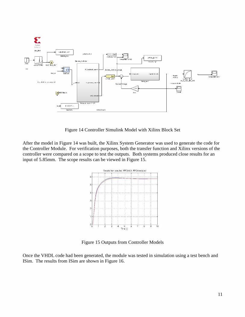
Figure 14 Controller Simulink Model with Xilinx Block Set
After the model in Figure 14 was built, the Xilinx System Generator was used to generate the code for the Controller Module. For verification purposes, both the transfer function and Xilinx versions of the controller were compared on a scope to test the outputs. Both systems produced close results for an input of 5.85mm. The scope results can be viewed in Figure 15.
Figure 15 Outputs from Controller Models
Once the VHDL code had been generated, the module was tested in simulation using a test bench and ISim. The results from ISim are shown in Figure 16.

12
Figure 16 Controller Simulation in ISim
The important signals in Figure 16 are idesired_disp, ifeedback, and opwm_duty. The signal idesired_disp was used for the controller’s desired velocity input. The signal ifeedback was used for the current velocity of the motor. The opwm_duty signal was the output voltage calculated by the controller. When idesired_disp is set to 3.88mm, the feedback steadily increases as the motor speeds up and the controller is producing an output of 41.75V. These numbers were very accurate according to the experimental results produced by the previous maglev group. The code for the controller can be found in Appendix B and the experimental results can be found in Appendix C.
Pulse-Width Modulation
A PWM module was created to control the power electronics. The PWM module was designed to receive an input value and produce a PWM with a duty cycle according to the input. The flowchart for the module is shown in Figure 17.
Figure 17 PWM Module Flowchart

13
The PWM signal was specified to run at a frequency of 1 kHz. Every pulse of the signal would go through the flowchart in Figure 17. The module was created using a counter and a comparison variable. The module would output a low signal until the counter passed the comparison variable, and then output a high signal until the full period was complete. The module would continue this cycle until the variable was changed, and then produced the new PWM signal. The implementation of this module shown in Fig 18.
Fig. 18 Oscilloscope View of PWM Module Implementation
Conclusion An FPGA board was selected for closed loop control of rotary inductrack magnetic levitation system height. The user will input a desired levitation height into the FPGA. The desired levitation height will be converted to a desired velocity. The error between the actual velocity and desired velocity is used by a discrete lead compensator with integral action to generate a PWM signal. This signal drives the power electronics which control the motor speed. All of the subsystems have been tested and are working correctly. Unfortunately, the complete integration and function of each module as a whole was not able to be completed before the end of the semester. This is due to difficulties encountered, mostly through the passing of signals between modules.

14
Patents Coffey; Howard T.
Propulsion and stabilization for magnetically levitated vehicles
U.S. Patent 5,222,436
June 29, 2003
Coffey; Howard T.
Magnetic Levitation configuration incorporating levitation,
guidance and linear synchronous motor
U.S. Patent 5,253,592
October 19, 1993
Lamb; Karl J. ; Merrill; Toby ; Gossage; Scott D. ; Sparks;
Michael T. ;Barrett; Michael S.
U.S. Patent 6,510,799
January 28, 2003
Levi;Enrico; Zabar;Zivan
Air cored, linear induction motor for magnetically levitated
systems
U.S. Patent 5,270,593
November 10, 1992

15
References [1] Kyle Gavelek, Victor Panek, Christopher Smith. Senior Project. “Closed Loop Control of Halbach Array Magnetic Levitation System Height”. Final Report, May 2013.
[2] Dirk DeDecker, Jesse VanIseghem. Senior Project. “Development of a Halbach Array Magnetic Levitation System”. Final Report, May 2012.
[3] Glenn Zomchek. Senior Project. “Redesign of a Rotary Inductrack for Magnetic Levitation Train Demonstration”. Final Report, May 2007.
[4] Paul Friend. Senior Project. Magnetic Levitation Technology 1. Final Report, May 2004.
[5] Post, Richard F., Ryutov, Dmitri D., “The Inductrack Approach to Magnetic Levitation,” Lawrence Livermore National Laboratory.

16
Appendix A
Data sheet for FB180 MOSFET
Data Sheet for 3120 optocoupler

17
Appendix A (continued)
Data Sheet for IRF520N

