climate resilient low cost buildings in marsabit county
TRANSCRIPT

CLIMATE RESILIENT LOW COST BUILDINGS IN
MARSABIT COUNTY
Technical Notes on Water Usage and Water Treatment
2018
DISCLAIMER:
Any part of these technical notes may be copied to meet local needs, without permission from the author or publisher, provided that the
reference to the source is made. While every care has been taken to ensure accuracy of the information given in this document, neither the
publisher, nor the authors and organizations can be held responsible for any damage resulting from the application of the described methods.
Any liability in this respect is excluded.

Contents
INTRODUCTION ............................................................................................................ 1
WATER MANAGEMENT .............................................................................................. 1
1 WATER HARVESTING ............................................................................................. 1
1.1 Roof catchment system ........................................................................................ 1
1.1.1 Gutter production ..................................................................................... 4 1.1.2 Split bamboo water gutter ........................................................................ 5 1.1.3 Sheet metal gutter .................................................................................. 10 1.1.4 PVC gutters ............................................................................................ 14
2 FOG COLLECTORS ................................................................................................. 16
2.1 Fog collector structure ....................................................................................... 16 2.2 Fog collector functionality ................................................................................. 16 2.3 Building fog collector ........................................................................................ 17
3 SAND DAMS ............................................................................................................ 21
3.1 Basic principles.................................................................................................. 21 3.2 Sand dam types and functions ........................................................................... 24 3.3 Sand dam implementation ................................................................................. 25
3.4 Site selection ...................................................................................................... 25 3.5 Designing the sand dam ..................................................................................... 31
3.6 Materials and labour .......................................................................................... 33
3.7 Constructing the sand dam ................................................................................ 35
3.8 Installing the water point ................................................................................... 38 3.9 Constructing the well ......................................................................................... 40
3.10 Operation & Management ................................................................................. 42 3.11 Sand dam monitoring......................................................................................... 43 3.12 Training sessions ............................................................................................... 44
3.13 Sand dam maintenance ...................................................................................... 45 3.14 Sand dam benefits .............................................................................................. 46
4 WATER STORAGE .................................................................................................. 47
4.1 Ferrocement water storage tank ......................................................................... 48 4.2 Hemispherical water storage tank ...................................................................... 57
4.3 Hemispherical water tank made of burnt bricks ................................................ 59 4.4 Hemispherical water tank made of Ferro-cement .............................................. 64
4.5 Plastic water storage tank .................................................................................. 66
5 WATER TREATMENT BEFORE USAGE ............................................................. 66
5.1 Biosand filter ..................................................................................................... 67
5.2 Boiling ............................................................................................................... 69 5.3 Chlorination ....................................................................................................... 70 5.4 Chlorine Based Purification Tablets .................................................................. 71 5.5 WATA Chlorine Generation Device ................................................................. 73

6 WATER DISTRIBUTION ........................................................................................ 77
6.1 Water pump ....................................................................................................... 80 6.2 Water distribution pipes..................................................................................... 84 6.3 Water distribution pipes maintenance plan ....................................................... 85 6.4 Recontamination prevention and leakage control ............................................. 86
7 WATER USAGE ....................................................................................................... 87
7.1 Foaming soap making ........................................................................................ 88 7.2 Water tap and showerhead aerators ................................................................... 89
8 WASTEWATER TREATMENT AND REUSE ....................................................... 90
8.1 Septic tank ......................................................................................................... 91
8.2 Greywater towers ............................................................................................... 92
8.3 Greywater uses for irrigation ............................................................................. 93
BIBLIOGRAPHY ........................................................................................................... 95

1
INTRODUCTION
The main objective for this issue of technical notes was to describe models for sustainable low
cost water management system. Such systems would be made and implemented using local
materials and possibilities and would employ local work force. Given the fact that the area of
work (Marsabit County) has a hot and arid climate that is mostly unsuitable for reliable all-
year-long water harvesting, it is, therefore, an objective to come up with a climate resilient and
adaptive system that would effectively manage the collection, storage and use and reuse of
water.
These technical notes include instructions on harvesting the rainwater, storing it, treating water
before using it, treating wastewater and reusing it, etc.
The county of Marsabit is located in the hot and arid northern region of Kenya, one of the most
underdeveloped regions in the country where water and energy are precious resources. Water
is an especially scarce resource, mainly sourced from boreholes, although many households
harvest rain water in the rainy season.
WATER MANAGEMENT
1 WATER HARVESTING
1.1 Roof catchment system
A rainwater harvesting system consists of three parts: a collection area, a conveyance system
and a storage facility (Figure 1). One of the ways to harvest rainwater is to use the roof plane
as a “water collection area”. Efficiency of the collection of the water and the water quality are
greatly influenced by the effective roof area and the materials that were used. The gutters’ and
the pipes’ material also affect the quality of rainwater. Since rainwater is acidic, chemically
inert materials such as wood, aluminum, fiberglass, or plastic are recommended [1].
Figure 1 Schematic of a typical rainwater catchment system [2]

2
The roof varieties, while producing the same output of water, differentiate in their cost
effectiveness. Different styles of roof can be seen in Figure 2. The roof style greatly affects the
guttering system that is going to be used.
Figure 2 Different roof styles [3]
Hip and Mansard styles are more complicated because they require gutters on all 4 sides
of the roof (four gutters on four sides).
Gambrel and Gable styles require two gutters on the two lower sides.
Shed and Butterfly styles are simpler as they need only one gutter, but the gutter itself
is required to be stronger and wider so that it can to withstand all the mass of water
falling during a heavy rainfall.
The roof catchment system does not have to be limited to a housing unit only but can also
utilize other premises such as: animal sheds, barns, storage facilities, garage etc. A shed can be
built in a simple and a cost effective way as it is shown in Figure 3. Farm animals can stay
under the shade during the day and sleep there at night. Rainwater storage tanks should also be
kept under the shade, covered from the sun’s heat. That will slow down the evaporation process.
Figure 3 A sample of the shed’s structure (left side) and example of the shed with a rain catchment
system and solar panels (right side) [4]

3
When using roof catchment system, it is recommended to clean the roof regularly for
maintenance purpose. The first time rainwater washes off the roof, there will be many
impurities such as sands, leaves, insects and, possibly, bird faeces. Among all the unwanted
extras, faeces is the main problem as it will turn rainwater into black water (wastewater that
contains faeces and urine). Blackwater needs to be treated differently and should not be used
as a source of drinking water.
Washing the roof helps to keep the roof clean from the abovementioned impurities. But it is
not a very effective solution, as in arid areas sand accumulates on the roof quicker than cleaning
takes place (which is the case in Marsabit County with its strong winds and sandy eroded soils).
A solution is to alter pipes system with additional dead-end downspout with a valve at its
bottom for discharging to prevent the first flush of rainwater to enter the storage tank (Figure
4). Dead-end downspout is installed right before the water reaches the actual downspout. The
first flush then can be used to water plants (assuming that Marsabit County is a rural
community, it is very unlikely that the water from the first flush would contain some hazardous
elements in it) or simply discharged into the environment.
Figure 4 Dead-end downspout [5]
In addition, a simple filter net system can be installed on the gutters or on the downpipe that
leads to the water tank to prevent leaves and smaller animals from getting into the gutter system
as shown in the Figure 5.
Figure 5 A gutter downspout cage [6]

4
1.1.1 Gutter production
Gutters can be produced locally either from wood (wood planks, bamboo splits), metal, or PVC
tubes. Gutters should always be inclined towards the downspout so that they will not overflow
due to the gravity pulling water in opposite direction.
Gutter production from local materials will be cost effective and easier to build and maintain.
Figure 6 illustrates different gutter material options.
Figure 6 Different gutter materials [7]
PVC made gutter pipe: Their advantage is their price. Due to mass production of plastic
gutters, they turn out to be cheaper and less time consuming than home-made wood or
metal gutters.
Wood planks as water gutters: reliable and cost effective solution wherever wood is in
abundance. Two wood planks are connected in a V-shape position. The connection is
further sealed to prevent any leakage from occurrence.
Split bamboo water gutter: due to its hollow core nature, bamboo makes a good choice
for guttering. Bamboo plants grow fast (90 cm per day) and thus needed amount of
bamboo can be easily grown in matter of months.
Sheet metal gutter: can be either purchased from somewhere else or produced locally
out of pre-purchased metal sheets. Forming gutters out of metal plates is called Cold

5
Forming. The automated process requires an expensive equipment and a constant
access to the electricity. The mechanical process is physically demanding as it requires
to push the metal plates through the rollers manually.
1.1.2 Split bamboo water gutter
The finished bamboo gutter looks similar to Figure 7 and 8.
Figure 7 Finished bamboo gutter [8]
Figure 8 One possible solution for a bamboo gutter connection [9]

6
The process of bamboo gutter making starts from choosing the right kind of bamboo. Make
sure to cover these basic steps [8]:
Choose mature (more than three years old) and completely dry bamboo poles. While
drying, the bamboo poles shrink in diameter. If the works is done during this process,
this will result in a weak and lose connections.
Avoid using poles infected with insects and poles that bear profound cracks in their
structure.
Do not try to adjust bamboo poles retrospectively when already placed. It is better to
choose the right poles with right diameters before the fitting.
Avoid the usage of conventional nails in bamboo joinery. Instead, go for either nylon,
steel or vegetal cord, or for one of many bamboo joint cuts.
Figure 9 Example of nylon cord and different joint cuts [10]
Next step would be splitting bamboo poles into gutter-like longitudinal pieces [11].
1. Press the bamboo cane firmly against an immovable object like a wall or a stone
boulder.
2. Make sure that cutting takes place at a thinner end of a cane. Then, press the hatchet (or
machete) right in the centre of the cane and start slowly hammering the blade into the
cane with a help of a mallet. Do it gently, adjusting if needed the position of the blade
along the way.
3. If the cut went off the centre then, to correct it, hold the un-split part of a cane by
stepping on it and with the smaller portion facing down and push the bigger part
upward. The difference in thickness should be corrected.
Figure 10 Steps of splitting bamboo [11]

7
Remember that bamboo has two different sides: a straight side and a bent side. For the gutter
work, it is suggested to use a straight side as it will give a smooth slope and thus will prevent
water from gathering in smaller cavities along the way [11].
Figure 11 Straight side of the bamboo cane [11]
Next important step will be to hollow out the bamboo pole. Any carving instrument will do the
job. Despite bamboo’s good water resistant properties it is a good idea to laminate inner side
of the gutter in a water protective coating/finishing. Any local oil or modern varnish that is
used for wood finishing can be applied to bamboo too.
Connections between different gutters are to be done through joint cuts. When fitting one
bamboo pole into another make sure that both of them have nodes in close proximity to the
point of connection. Otherwise, there is a great risk of bamboo snapping and collapsing [8].
Figure 12 Left: bamboo snapping underweight; Right: correct connection with nodes in close proximity [8]

8
One method that is widely accepted in gutter making is, so-called “Bamboo joining method
with dowels and lashing” where the peg should be placed in a column parallel to the rafter as
shown in the picture below [8].
Figure 13 bamboo joining method with dowels and lashing [8]
It is also a good idea to try to seal all the connections with a sealant material which is suitable
for drinking water.
Usually bamboo gutters are made out of large diameter split bamboo poles with all the nodes
removed. This can be fixed to the roof either by iron hooks, or by long pieces of wood, or tree
wigs fixed to the rafter.
The size of the gutter to choose is determined by the sheer size of the roof area and its slope.
Table 1 gives an idea of this relation [12]:
Table 1 Roof area and gutter width relation [12]
The depth of the gutter will be approximately one-half of its width.
For the installment of a gutter it is instructed to follow these steps [12]:
1. First, measure the length of the roof from wall to wall in order to determine the length
of a bamboo gutter.
2. Lay the split bamboo on a flat surface and measure to where it needs to be cut. Draw
the lines on the exterior side.

9
3. Wrap a piece of masking tape around the place where you’re planning to make a cut. It
will prevent any splinters on the surface.
4. Cut the bamboo with a saw.
5. After that, remove the masking tape from the gutter.
6. Fix the gutter to the roof.
There are several ways how to implement this final step – fixing the gutter to the roof. Some
of the most common ways are mentioned here.
Figure 14 Fix the bamboo gutter to a wooden roof structure using cross-fixed wooden gutter holders [12]
Figure 15 Fix the bamboo gutter to a wooden roof structure using wooden eaves [12]
Figure 16 Fix the bamboo gutter with iron gutter holders to a wooden roof structure using wooden eaves [12]

10
Figure 17 Fix the tree twig gutter holders to the roof structure with rope, iron wire or nails [12]
For the dead-end downspout and the main downspout the technology is the same. But,
naturally, there is no need for splitting there. It is advised to use full grown mature bamboo
trunks for downspouts as it would have to be able to carry the load of water for the whole
duration of the rain [12].
1.1.3 Sheet metal gutter
If the gutters are to be produced locally, coated and pre-treated steel plates should be purchased
in advance from somewhere else. Gutter making out of steel plates is very easy, but it requires
either a metal bending machine or if done manually, it is labor intensive. There are only two
steps in the process. Firstly, you will have to measure and line up the distances on the metal
plate. Secondly, place the plate under a metal bending machine and push up to the required
angle.
The simplest shape for metal gutter is “V-shape”, where the plate is bent along its middle axis
up to 90o+ degrees.
Figure 18 V-shape bending [13]
In theory, that shape can be achieved with only one bend, but in practice, it is rarely the case.
Instead, a three bent model is used.
1st bend: makes a flap designated for hanging the gutter onto roof (-90o)
2nd bend: creates main cavity for water runoff (90o to 120o)

11
3rd bend: creates an edge fold (-180o)
Figure 19 Practical V-shape model with 3 bends
V-shape metal gutter instructions:
1. Start by finding the right sized strips of galvanized coated (optional) metal.
Figure 20 Galvanized coated metal strips [14]
2. Make the first bend.
Figure 21 First bend [14]

12
3. If an inverted bend as in the figure below is made, the bend will be used to connect the
gutter to the roof.
Figure 22 Additional bends for connecting to roof [14]
4. Fix the gutter to the roof like this
Figure 23 Fixing to the roof (AutoCad visual representation)
Another possible shape for metal gutters would be a square shape, with two 45o folds in the
middle. This one has less structural stability over long distances so intermediate bracing is
required but it can carry more water flow at a time. There are also many variations about a
square shape. These variations are presented in a picture below.

13
Figure 24 Different styles of square-like shapes [15]
Figure 25 Square shaped metal gutter [16]
Round shape is quite popular as well, but achieving such shape with a simple press-braking
(bending) machine is not possible. To achieve such roundness, an automatic cold rolling
machine has to be purchased.

14
Figure 26 Round shaped gutter [17]
1.1.4 PVC gutters
PVC gutters are serviceable for many-many years and they are not prone to corrosion. It is
relatively easy to operate and requires much less work to be done than bamboo gutters [18].
There are two main ways how to make a rain gutter with the use of PVC pipes. One either buys
an already pre-made PVC gutter kit to assemble it on-site or he/she uses cheap PVC pipes to
carve out necessary details.
For this second method, the idea is just like it was with the bamboo gutters. PVC pipes ought
to be divided with a saw along their diameter lines. It is better to choose wide enough PVC
pipes as they would have to be able to carry the water during the heavy rainfall without
overflowing.
PVC details can be also used as connection details, where the gutter meets the downspout and
where the downspout meets the water tank. Either a rubber band or a water resistant sealant
should be placed in the area of connection.
For the hanging part, PVC gutters would need additional hangers made of either metal (metal
brackets, metal plates, bolts, screws) or wood (wooden hangers, wooden porches, wooden
eaves). No matter which way was chosen, the angle at which the gutter is placed should always
slope towards the water tank.
If the purchasing is possible, estimation on prices for metal made gutters can be found for
example from Metro Plastic Kenya Ltd, located in Nairobi. An example of the pipe prices is
presented below in Table 2 [19].
Table 2 Prices of the pipes (checked on 13.09.2016) [19]

15
Enlisted prices are in KES (Kenyan Shillings). According to Google Finance exchange rate 1
Euro equals 113.6091 KES (checked on 13.09.2016).

16
2 FOG COLLECTORS
Alternative way of harvesting rainwater is a relatively new fog harvesting technology, the use
of which has increased significantly in last decade.
2.1 Fog collector structure
Fog harvesting collector is made of either a single of double layer of mesh supported by two
posts rising from the ground. The size of mesh can vary greatly. Varying materials can be used
for mesh production, including nylon, polyethylene or polypropylene netting. Those can be
produced to various densities capable of capturing different quantities of water from the fog
[20].
Collectors must be placed on ridgelines perpendicular to the wind direction. That way they will
be able to capture and collect water when fog sweeps through. The number of fog collectors
and size of their respective meshes is constrained by local topography, water demand and
availability of financial resources and materials. Example of a fog collector system is shown in
the figure below [20].
Figure 27 Fog catchers [20].
2.2 Fog collector functionality
The collector and conveyance system functions due to gravity. Water droplets that get into the
mesh run downwards and drip into a gutter at the bottom of the net from where they are
channeled via pipes to a storage tank or cistern. Typical water production rates from a fog
collector range from 200 to 1000 litres per day. Efficiency of collection improves with larger
fog droplets, higher wind speed, and narrower collection fibres/mesh width [20]. An example
of different fog catchers can be seen in Table 3.

17
Table 3 Water collection rates from fog catchers [20]
PROJECT Total collecting surface
(m2)
Water collected (litres/day)
University of South Africa 70 3,800
Yemen 40 4,500
Cape Verde 200 4,000
Dominican Republic 40 4,000
Eritrea 1,600 12,000
The cost for a fog collector system may vary greatly based on such limiting factors, such as
access to the site, labor cost and availability of construction materials. “Small fog collectors
cost between $75 and $200 to build. Large 40m2 fog collectors cost between $1,000 and $1,500
and can last for up to 10 years” [20].
Fog collectors are easy to build, maintain and use. Thus, with a simple guidance, fog collectors
can be locally reproduced in order to meet the demand for water [20]. Below is a picture from
Ngong hills, Kenya, where the locals have produced their own fog catching system.
Figure 28 Handmade fog catching system [21]
The advantage of such system is that the atmospheric water is generally clean, does not contain
harmful micro-organisms and is immediately suitable for irrigation purpose. Once the technical
supervision provided and construction materials are procured, the construction process is
relatively straightforward and can be undertaken on site [20].
The disadvantage is the fog harvesting technologies depend on a water source that is not always
reliable, because the occurrence of fog is uncertain [20]. Thus, further meteorological research
should be conveyed to establish, whether or not this system is suitable for Marsabit County.
2.3 Building fog collector
If no preliminary survey can be conducted on the quality and quantity of water that can
potentially be harvested from fog, then it is advised to start by making several pilot fog

18
collectors in different places, at a different height and of a different content and, depending on
their output, either expand it to a potential fog farm or abdicate the project entirely.
Figure 29 Example and dimensions of a small scale fog catcher system [22]
Step-by-step instructions on how to produce a single fog collector are shown below:
1. Preparing the frame
Make a square frame 100x100cm. The frame can be done from wood, bamboo or PVC
pipes. Fix the sides with nails or screws.
2. Adding the gutter
Gutter is needed to convey the water into the water tank. The gutter can be made from
bamboo, or steel, or from a laterally cut PVC pipe. The gutter needs to be inclined towards
the downpipe. Otherwise, some water will be lost due to the forces of gravity.
3. Adding the downpipe
Water condensates slowly on the net, and runs down when pressure is built. Hence, there
is no need for an actual downpipe. It is enough to simply connect a rubber made water hose

19
to the gutter. The other end of a hose must be placed into the jar or container appropriated
for water collection. All connections must be tightly sealed.
4. Fixing the net
The net’s quality is crucial for an effective water production. There is no easy way to
produce such net locally, but it could be imported from elsewhere. Taking into account that
fog collection is getting increasingly popular among developing countries, the material for
the net is no longer a rarity and should be easy to find.
5. Preparing the foundation
Excavate two holes for the foundation at the distance of 1 meter from each other. Make
sure that the soil is hard enough on the sides and compressed in the bottom, so that the
structure will not fall under its own weight. Take into account the heavy winds. Cast the
concrete.
6. Placing wooden poles
Place a wooden pole in the middle of each hole. Make sure that they are parallel to each
other. Secure it by pouring concrete around them. Wait for them to fix properly into the
concrete.
7. Fixing the frame
Fix fog collector’s frame with the net and an already attached water gutter and a downpipe
water hose to the sides of the poles at its top. Now, the system is ready to be used.
! Alternatively, the whole structure can be connected beforehand and only then fixed into the
ground.
! Note, that the water form such structure while being crystal clean cannot be used directly for
drinking as the safety and cleanliness of a gutter cannot be guaranteed. Since the gutter is
exposed to the environment, it is assumed that it will gather some sand and dust on it,
potentially even fecal matter. Thus, if intended for drinking, the collected water should go
through a treatment process. Alternatively, the water can freely be used for irrigation, cleaning
and other purposes.
If the experiment with fog collectors is proved to be positive, then the whole farm of such
collectors can be installed at a short distance from each other. The nets can become wider and,
depending on the pilot results, they can be placed either lower or higher.
These collectors can be further connected into one system by intersecting water hoses and
leading the water to one place. The example of such system is presented below.

20
Figure 30 Fog collector system in Moroccan desert [23]
Figure 31 Fog collector system in Moroccan desert [23]

21
3 SAND DAMS
3.1 Basic principles
Sand dam is a small dam that cuts through the dry riverbed of a seasonal river. The dam
simultaneously works as a water stopper and as a storage facility. Water is stored in the sand
that forms naturally over a period of time due to sedimentation process on one side of a dam.
The sand gets charged with water either from the surface runoff during the rain or from
groundwater flows. Water stays in the sand and partially in the riverbanks on both sides of a
river [24] [25].
Figure 32 Typical sand storage dam during the dry season [24]
Water level in the aquifer drops during the dry season due to abstraction of water, evaporation,
leakage and precipitation through the soil or a bedrock. In the same time, water level gets
replenished due to subsurface flow from the riverbanks towards the riverbed and the dam itself.
Due to the large storage volume and the retention of water in sand, the dam can provide water
for people and vegetation throughout the dry season [24].
Figure 33 Schematic cross section of a typical sand storage dam [24]

22
Sand dam is an improvement over a more traditional surface water dam that stores water in an
open water retaining basin. Surface dam has a great disadvantage as a big portion of its water
is lost due to surface evaporation. This is not an issue in bigger reservoirs as only surface water
is affected by it, yet shallow small-scale reservoirs can lose all of its water in a matter of weeks
if the climate is too harsh. Another disadvantage of surface water dams is that they are much
easily infested and contaminated. Sand dams effectively protect the water from evaporation
and can keep it in its aquifer for a much longer time.
Advantages of sand dams over surface dams [25]:
Less evaporation (water storage in sand)
Less contamination with sand (no direct contact of water with livestock and other
animals)
Better infiltration (water flowing through the riverbed of sand, disinfection or filtration)
No more breeding of mosquitoes (reduced risk of malaria)
Low cost structures (built by community)
Proper maintenance (can be maintained by community)
Long term sustainability (high community involvement and commitment).
In many semi-arid regions, most of the peak river discharge is lost downstream and the storage
and retention of water after rainfall events is limited. This happens due to geomorphology of
the upstream, catchment with steep slopes and silty and clayey soils [24].
The main function of the sand dam is to retain and store water. This is why it obstructs
groundwater flow with a wall anchored in an impermeable riverbed. The aquifer can be filled
with water after one or two rainfalls yet it might take several years for it to fully be covered in
sand. It depends on the amount of sand deposits in the area. Water will be available in the sand
as long as groundwater flow from riverbanks continues [24] [25].
It is wise to take soil- and water conservation measures in the upstream areas, as it will increase
the infiltration of rainwater and the flow of groundwater. Raised water table in the riverbanks
results in a groundwater flow from the riverbanks towards the riverbed. Downstream of the
dam, the groundwater flow continues its natural course [24] [25].
Water balance components: ET Evapo(transpi)ration from slopes
E Evaporation from riverbed
P Precipitation
R Surface runoff from slopes to river
Bs Groundwater base flow from slopes to river
Bf Shallow and deep longitudinal base flow
Qout River discharge outflow over downstream dam
Lout Leakage underneath and around downstream dam
Qin River discharge inflow over upstream dam
Up Use of water (abstraction)
Gr Loss of water into the ‘impermeable ground
Figure 34 Water balance components [24]

23
Filling the sand dam aquifer
The water is stored in the sediment and sand. It takes several continuous rainfall seasons for
the aquifer to completely fill up with sediment material. Sediment material depends on the river
flow velocity and on the material that comprises the riverbanks. Sand and silt mostly fill up the
aquifer at the beginning of a rainy season. It comes from places that are poorly protected against
soil erosion [24].
At the end of a season, when the river flow decreases, coarse elements (small rocks, stones
etc.) are deposited. Without a sufficient amount of course material, the base flow energy will
lead to river bed erosion. The type of material that can be found in the riverbed prior to sand
dam construction is a good indication of the sediment that can be expected to accumulate
behind the dam. These sediments form a river delta upstream of a dam. In this delta area, the
velocity is high enough to transport coarse sediments. Where the ‘delta’ stops, a sudden drop
in flow velocity occurs causing coarse sediments to settle, building the ‘delta’ further towards
the sand dam. Continuous repetition of this process causes the ridge of sand to move towards
the dam, eventually filling the total volume behind the dam [24] [25].
Figure 35 Schematic representation of the sedimentation process [26]
The water also carries finer materials with it, such as silt and clay which mostly go over the
dam as their settling velocity is low and they largely stay in suspension [24].
After the heavy rainfalls, the peak discharge in the river will decrease until the base flow. If
the river runs dry completely, residual silt layers on top will dry and crack. Animals and people
walking on the riverbed will pulverize this dry silt layer, making it susceptible for wind erosion
[24].
Sedimentation will continue until the ‘delta’ reaches the top of the sand storage dam. Granite
hard rock will produce coarse sand while shales will produces fine (clay or silty) material. It
can take several wet seasons to fill the dam, depending on the availability of coarse sediments,
height of the sand dam, river discharge, catchment slope and rainfall intensity [24].
It is recommended to build sand dams in stages, since the amount of coarse material is limited
and base flow is small. Typically, the first stage of a sand dam is about 50 cm high. Sand dam

24
construction should not be limited to only one. It is advised to wait until the first sand dam is
fully matured as any construction upstream might disturb its sedimentation process and its
sediment composition. The next sand dam can be built right at the end of a catchment ‘delta’
area for a previous dam [24].
3.2 Sand dam types and functions
The primary function of a sand dam is to increase the availability of water by storing water in
the riverbed and in accumulated ‘delta’. The water is stored in voids between sand particles.
Depending on the porosity of the sand, it can hold up to 35% of its volume. Besides this, sand
dams can have other functions and positive side effects such as [27]:
Recharge of regional groundwater: A cascade of sand dams along the river course
increases groundwater levels in a larger area. It positively effects the environment
(vegetation) in the surroundings of the dam.
Rehabilitating of gullies and sand harvesting: Sand dams can rehabilitate eroded
gullies. If a sand storage dam is built for this purpose, the dam does not have to be
impermeable.
Figure 36 Sand dam in Kituï [26]
Sand dams can be classificatied based on the materials that it was made of [25]:
Masonry dam: A dam is built out of stones that are bonded together with mortar. This
type of construction is relatively expensive to make and it is time consuming yet local
artisans can do this. Masonry dams are durable and can be turned into higher structures.
Reinforced concrete dam: This dam is made of a thin wall of reinforced concrete. It
is durable, relatively expensive but suitable for any height.

25
Earth dam: Consists of impermeable soils (clay or black soils). Although earth dams
are most cost-effective, they cannot store large quantities of water which makes them
less suitable. An earth dam can easily be damaged and even destroyed by underground
flow.
3.3 Sand dam implementation
Sand dam implementation is divided into several steps that are presented below and are
expanded in further chapters. The following steps for implementation are identified [25]:
1. Site selection and community involvement
2. Engineering and Design
3. Water use assessment
4. Excavation and construction
5. Operation and maintenance (establishment of water management, water committee,
care takers and provision of trainings)
6. Monitoring and Evaluation
Figure 37 Sand dam implementation steps [25]
In this manual the focus will be on masonry made dams with or without a reinforced foundation
and a u-shaped spillway. The choice in favour of this construction was made after examining
existing conditions and available materials in the area of a project [25].
3.4 Site selection
The most important step for a successful sand dam is to choose the right place for the
construction. Accuracy in site selection will determine the final success of the dam.

26
Community involvement is also an important factor as they are the ones who will construct
the dam, maintain it and use it daily basis.
Sand dam location can be selected through 3 steps in relation to different scales [25]:
River basin or catchment scale - Selecting potential sub catchments from a probability
map based on a desk study
Sub-catchment scale - Selecting potential riverbeds based on field data regarding the
physical and sociological aspects
Riverbed - Selecting of sand dam location(s) [25].
Figure 38 Identifying appropriate scales [25]
Selecting potential catchments for sand dams
An entire catchment has to be assessed before selection of a suitable place for a sand dam.
Quick scan is needed to assess the sub catchment areas where:
a) Water buffering needed because there is no natural water buffer
b) Physical conditions are suitable for sand dam construction
c) There is a demand for water buffering [25].
Quick scan is based on satellite information, internet database and available digital maps. The
type of maps that are usually used for a ‘quick scan’ analysis include:
1. Topographical Map:
Gives general information about catchment area by showing the rivers, their extent and
characteristics. Usually, it also includes information regarding the socio-economic
infrastructure (for example: location of local villages and roads) [25].
2. Digital Elevation Model:
Digital Elevation Map (DEM) informs about the morphology of the area (slopes and
elevations). Based on this knowledge, a local drainage direction map can be calculated. It
will give the drainage pattern of the catchment [25].
3. Geological Map and Soil Data:
Morphology and geology of the catchment informs about the rock formation and soils in
the upper catchment and in the riverbed. It can indicate that the riverbed is a hard rock and
thus impermeable. Catchment geology, with discharge characteristics and the slope,
together, determine the grain sizes, which can be actually stored in the sand dam. A

27
geological map can indicate whether a catchment has the potential to produce (coarse) sand
[25].
4. Aerial Photographs and Satellite Images:
Aerial photographs and satellite images can support locating sandy riverbeds based on the
morphology. Aster satellite images can also be used to indicate sandy riverbeds and
different types of geology through the remote sensing techniques [26].
5. Precipitation and Evaporation Data:
Knowing the levels of precipitation and evaporation is essential when building sand dams.
Precipitation may influence discharge characteristics (base flow) and thus also the
availability of coarse grained material in the riverbeds [25].
6. Flood data:
In order to determine the maximum flood level and thus the minimal height of the riverbank
flood data is required. It also provides information on discharge characteristics of a
catchment during a rainfall event [25].
The analysis of above mentioned maps and data usually requires an expertise from specialists
who have geographic information system (GIS) experience and access to shape files and will
result in a potential map for a whole catchment. Sometimes ‘Quick Scan’ is not available. In
which case the site selection happens within the sub-catchment area [25].
Selecting potential riverbeds and river bed sections
When a potential catchment area is selected, nest step is to select potential riverbed or a section
of it. This requires more detailed assessment. Main criteria for selecting include:
The presence of communities (nomads or permanently – dry period)
The slope of the river bed: most suitable locations have a slope of 2 to 4 percent)
Average width of the river, which should not exceed 25-50 meter
The rivers should be underlain by bedrock
Based on these criteria, a small number of river bed sections are selected for field visits, which
is needed to collect information and to consult the communities [25].
“Checklist for river section inspection and ranking [25]:
1. Location and types of water-indicating vegetation:
A good indicator for the presence of groundwater is current vegetation. Depending on the
species, the groundwater depth and storage of water can be estimated [25].
2. Location of waterholes, their depth to the water table and quality of the water:
The presence of waterholes is an indication that the riverbed contains deep water storage.
The water quality in the waterhole is an indication of the quality of water which can be
harvested [25].
3. Location and types of rocks and boulders:
If large boulders are present in the riverbed, special care should be taken in choosing the
location. Preferably the sand dam has to be built on a hard rock or compacted and strong
soil [25].

28
4. Grain size of the sand particles in the riverbed:
The grain sizes which are present in the riverbed are a good indication of the material
which will fill up the sand dam reservoir after construction. Coarse sand is preferred, since
it has a higher infiltration capacity and water can be abstracted more easily [25].
5. Shape and dimension of the riverbanks:
Suitable riverbeds for sand dam consist out of high riverbanks. During flood events the
river should not flow over the riverbanks, because this can cause erosion of the riverbanks,
flooding of downstream located villages and it might cause the river to change its course.
6. Maximum width of river is 25 meters:
Preferably, riverbed width should not exceed 25 meters. The reinforcement required to
construct such kind of long dam walls is too expensive; hence the sand dam will not be
cost-effective [25].
7. An impermeable bedrock layer:
To ensure storage within the sand dam aquifer, losses to deeper groundwater should be
minimized. Therefore, the dam should be built on solid bedrock or an impermeable layer
[25].
8. Suitable construction materials:
Locally available construction material, such as sand, rocks, bricks, etc. determine the most
cost-effective way of sand dam construction [25].
9. Presence of riverbed crossings and roads:
Rural roads often cross riverbeds. Preferably a sand dam is located near these crossings
and can be easily reached through existing roads (also for transportation of materials)
[25].
10. List of houses, schools and shops near the riverbed:
Local people benefit from the sand dam, may it be direct or indirectly. By measuring these
positive social impacts before and after implementation, the actual social impact can be
determined [25].
11. Land rights:
Agreements based on rules and regulations (or bylaws) are needed to assure fair use and
access to water for collective and individual usage. To avoid conflicts, special care should
be taken in areas where the dam site is owned or used by two or more villages or several
individuals [25].”
This checklist comprised of 11 points is based on expert knowledge of Nissen-Petersen (2006)
[27]. The information is gathered during the field visits form the social leaders and the
community and later integrated into a map, resulting in a ranking of the riverbed sections [25].
Selecting sand dam location
Based on a produced maps, 2-3 locations that are selected as potential dam sites are further
evaluated. These specific sections will be visited together with the community representatives
for data collection [25].

29
“Measurements that needed to be taken at the site [25]:
The depth and coarseness of the sand at different levels
Most water can be retained and stored in riverbeds which have course sand. The porosity
and the water holding capacity of sand can be determined through this method:
o A 20 litre container with a plug in the bottom is filled with sand from the riverbed.
The sand is slowly saturated with a measured volume of water. Then the plug is
removed from the bottom of the container. The volume of water which has drained
out of the sand within one hour is taken as a measure for the extractability. Table
4 gives values of extractability of water in different soils. This shows that coarse
sand has the highest extractability making it also preferred for storage in the
aquifer [25].
Table 4 Comparison of different types of sand [25]
Silt Fine Sand Medium Sand Coarse Sand
Size (mm) < 0.5 0.5 – 1.0 1.0 – 1.5 1.5 – 5.0
Saturation 38% 40% 41% 45%
Water Extraction 5% 19% 25% 35%
Depth and type of basement and depth of groundwater
The sand dam must be constructed at the location where the impermeable layer is closest
to the riverbed surface. The depth of the sand in the riverbed can be surveyed by using an
iron rod with a diameter of 16 mm. Notches should be cut in the probing rods for every 25
cm, to collect sand samples when the rod is pulled up. A hammer is needed for hammering
the rod into the riverbed, together with a tripod ladder used for hammering long probing
rods. This survey is executed using the following procedure below [25]:
1. Hammer the probing rod straight down in the middle of the riverbed, until it hits the
floor under the sand with a dull sound
2. Mark the level where the water is encountered and the depth of the bottom
3. Pull the rod straight up without twisting
The procedure described above is repeated at regular intervals, for example 5, 10 or 20
meters. The data gathered by this particular survey results in a map with profiles of the
river section and cross sections at the locations. This map shows information about the
river length with approximate dimensions and specific information (width, locations of
cross-sectional, longitudinal profiles, water-indicating trees and waterholes). Based on
this a more precise estimation of the water storage capacity can be acquired and the
location of the dam is decided [25].
Gradient of the river bed
Measuring the gradient of the riverbed can be done by using a circular transparent hose,
half-filled with water. One person should stand at the starting point, using the levelling
tool. Another person should stand upstream of the person holding the levelling tool, with a
long vertically placed pole. The person with the levelling tool makes sure that the water
levels in the tube are in aligned. The other person should indicate where this sight line
crosses the pole. The height at which the line of sight crosses the pole is measured from the
surface of the riverbed (parameter y [m]). Also the distance between point No. 1 and point
No. 2 and the height of the eyes of the person holding the levelling tool is measured

30
(parameter z [m]). With these figures the gradient (parameter w [m]) can be calculated
using the following formula [25]:
W = ((z – y)/x)*100 = gradient [%]
Figure 39 Measuring the gradient [25]
Width of the riverbed and height of the riverbanks
The figure below shows an example of a longitudinal profile. It shows the points at which
the sand is deepest (here: 4.0 m deep between 55 and 60 metres) and where natural
subsurface dykes (of solid bedrock or impermeable soil) are located (for example at 40, 70
and 85 metres). The locations with deep sand are the potential reservoir of a sand dam and
the natural dykes are potential locations for a sand dam. The actual location of the dam
can be determined after making a longitudinal profile of the selected riverbed section. The
exact place is selected based on the deepest point with the largest storage reservoir. In the
graph this is at 60 meters [25].
Figure 40 Longitudinal profile of riverbed [25]
By knowing the longitudinal and cross-sectional profile, a calculation of the reservoir
capacity can be made. The figure below gives an example of the deepest cross-section. It is
important to take measurements every 1 or 2 meters across the riverbed to determine the
riverbed morphology. If the cross-section is combined together with the longitudinal
profile, the storage volume can be calculated accurately [25].”

31
Figure 41 Cross-sectional profile of riverbed [25]
3.5 Designing the sand dam
The sand dam is designed based on the outcome of the water assessment conducted in previous
chapter. In addition to this calculation, the dam is designed according to the specific
morphology of the riverbanks and the riverbed [25].
Sand dam can be defined on five main parts:
Dam wall
Spillway
Wing walls
Stilling basin
Abstraction well [25].
Dam height
In order to determine the height of the dam, one should know its absolute maximum flood
level. Water level should not be above the riverbanks, otherwise all sorts of structural
damage can occur. Information regarding the flood level can be obtained either from the
locals or from careful observance on the site for the signs and marks of flooding [25].
The maximum discharge level can be calculated in 3 ways:
Maximum discharge level calculated by the highest flood level
Calculating the discharge at the selected location using a certain return period (for
example a rain event with a return period of 50 years) or otherwise, using a rainfall-
runoff model or a mathematical formula for rainfall runoff.
Area Slope Method [25].
Figure 42 Cross section with maximum flood height [25]

32
Maximum discharge in riverbed section [25]:
Q = 1/n * A * R2/3 * S1/2
Q = maximum discharge in riverbed section (m3/s)
n = Manning roughness of riverbed
A = wetted cross-sectional area (m2), by: ½*(channel width + riverbed width)* flood
height
P = wetted perimeter (m), by: B1 + riverbed width + B2
R = hydraulic radius (m), by: A/P
S = slope of riverbed (m/m)
Q = c * Ls* H3/2
Q = maximum discharge in riverbed section (m3/s)
c = 1,9 (constant depending on spillway shape, here: broad crested weir)
Ls = length of spillway (m)
H = height of spillway (m)
Cross-sectional width dimension of a sand dam [25]:
Figure 43 Cross section of a sand dam [25]
Gf = gross freeboard (m) Lw = length wing wall (m)
Hf = height freeboard (m) Lwe = length wing wall extension (m)
Hd = total height of dam (m) Ls = length spillway (m)
Hs = total height of spillway (m)
Depth of the wing wall determination [25]:
In loose riverbanks: approximately 10 meters into the riverbanks.
In hard (consolidated) soils: approximately 7 meters into the riverbanks.
In hard and impermeable soil: approximately 0 – 3 meter into riverbanks.
In rock formation: no need of constructing in riverbanks.
If there is risk of channel shifting, 15 meter wing walls are needed for precaution.

33
The length of the wing wall (Lw) is approx. 2 meters into the riverbanks. The length of the
wing wall extension (Lwe) should be approx. 5 meters [25]
Stilling basin dimensions [25]:
SL = c * L1/3 * H21/2
c = 0,96 (constant)
SL = length of stilling basin (m)
H2 = height of freefall (m): height of water level upstream –height of water level
downstream
Figure 44 Cross sectional profile of a sand dam body and its dimensions. [25]
The thickness of the stilling basin (Sh) should not be fixed to be maximum 0.3m, as it depends
on the uplift pressure and impact load. The thickness can be even higher than 0,3m, if the
underneath material is a lose formation. This way it prevents possible collapse of the structure
[25].
3.6 Materials and labour
For a successful construction, it is important for local people and communities to be directly
involved in the process. They have to be able to work with site specific materials. Site specific
materials like sand and stones will greatly reduce the costs of transportation and handling [25].

34
Figure 45 Cross sectional profile of a sand dam body [25]
Table 5 Construction materials needed for masonry dam [25]
Stilling basin 1:3 mortar
Large boulders
Dam
1:4 mortar with well interlocked stones (cement : sand : hard core ratio =
1:4:9-12)
Upstream wall and top of dam plastered with 1:3 mortar (30mm)
Foundation
1:3 mortar foundation (100mm)
1:4 mortar with well interlocked stones (cement : sand : hard core ration =
1:4:9-12)
Reinforced bars of barbed wire (400mm spacing)
Table 6 Bill of quantity for materials and transportation costs in EUR (2007) based on costs
for similar actions in Ethiopia [25]
Description Unit Unit cost
(EUR)
Total quantity for
a sand dam
Total cost
(EUR)
Cement 50 kg bag 19.7 241.8 4762.73
Reinforcement bars ½ Dia’ (12m) Pieces 0 0.0 0
Reinforced bars ¼ Dia’ (12m) Pieces 0 0.0 0
Barbed wire 20 kg roll 10.3 6.0 62.3
Timber 2”x 2” M2 1.80 52.0 94.55
Polythene paper g 1000 Meter 2.30 104.0 236.36
Reinforced bars Dia’ (10m) Pieces 21.20 3.1 66.20
Reinforced bars Dia’ (6mm) Kg 2.12 51.5 109.25
Black wire Kg 2.12 3.9 8.33
C.I.S. Nails Kg 2.73 2.3 6.36
Stone hard core M3 4.70 233.2 1104.25
Sand M3 2.90 66.3 190.90
Water M3 21.20 37.4 794.25
Other construction equipment (V. tools,
Hand pump, Mould for well concrete rig) Unit 1136.36 1.0 1136.36
Camping site for skilled labourers Unit 984.85 1.00 984.85
Total *9556.50
*Prices and quantities are highly variable: these depend very much on the site location and
local markets.

35
In the following table an example is given of the bill of quantity for labour costs. The number
of masons needed and days required to construct the sand dam depend largely on the size and
location of the dam [25]. The costs can vary as well.
Table 7 Bill of quantity for labour costs in EUR (2007) based on costs for similar actions in
Ethiopia [25]
Description Unit (days p.p.) Unit cost
(EUR) Total days
Total cost
(EUR)
4 masons 45,8 7.58 183.3 1388.64
10 mason assistant 31 2.30 312.0 709.10
15 community workers 50 0 750 0
Total 2097.73
3.7 Constructing the sand dam
Excavation
The dam must be fixed on the impermeable river bed. This requires the riverbed to be excavated
until the hard rock is reached. The excavation works requires marking the position and the size
of the dam beforehand [25].
To estimate the size of the trench, following factors must be taken into account [25]:
Measure appropriate distance from one of the river banks and fix a peg
Fix another peg across the river, perpendicular to the river course at the appropriate
distance
Use a plumb bob and line mark several points from the building line and fix pegs.
Figure 46 Setting a trench with pegs [25]
After the marking is done, following trench (60cm) is excavated. The depth of the trench is
determined by the depth of impermeable layer which will obstruct seepage below the sand
storage dam. Removed soil should be placed downstream to avoid filling the aquifer [25].

36
If an impermeable layer is presented with the bed rock, the trench should be cut into the rock
to ensure joining of the rock and mortar. It is wise to check any suspicious place by pouring
small amount of water on it. If the water leaks away, the piece of rock must be removed [25].
If an impermeable layer has clay, the trench must be dug in for about 50 cm to avoid seepage.
After these conditions are met, the trench is ready for dam setting and construction [28].
Figure 47 Trench excavation [25]
Construction starts with placing the reinforcement columns vertically in the trench, followed
by the construction of the foundation blinding slab. Reinforcement is only required if a large
or high dam is constructed. After this, the second horizontal reinforcement layer is placed,
followed by the second foundation blinding slab and finally the actual masonry structure (of
hard core and mortar) [28].
Construction of the dam follows a number of subsequent steps [25]:
“Step 1: Placing reinforcements
These are placed vertically across the entire length of the dam at an interval of 2.5 m. They are round bars with a diameter of 12.5 mm and the length depending on the complete height of the dam. The amount necessary can be determined as follows [25]:
where Ld is length of the dam in meters.
No. of columns = Ld
21
37
Mark the positions of the columns along the building line, then measure the vertical depths to the bottom of the trench and record them as in the example below. No 1 = 2.53m, No 2 = 2.27m, No 3 = 3.05m, No 4 = 1.97m Round bars of the columns are firmly grouted into holes on 5cm deep that have been cut into the foundation at the requested depth (depending on the bedrock material or soil type) [25]. Step 2: Making the foundation blinding slab A layer of cement mortar (1:3) is prepared on the foundation to the depth of 5cm. When there is no foundation rock the vertical iron bars are placed in the mortar layer [25]. Step 3: Constructing the first horizontal reinforcement layer After the mortar layer 12 strands of barbed wire are evenly divided over the building slab along the dam [25]. Step 4: Constructing the second foundation blinding slab The barbed wire is covered by 5cm of foundation blinding slab [25]. Step 5: Masonry comprising hardcore and mortar substructure After the foundation blinding slab sets and holds the columns firmly, the foundation trench is filled with masonry comprising clean hardcore and mortar (1:4). Mortar for filling should have more water. The joints between the rocks are filled 25mm of this mortar. The rocks should be tapped well to settle completely into all voids. When the filling reaches the level of the back flow, the construction of the backflow should be done alongside that of the wall as shown. Masonry comprising is extended to the wind wells [25]. Step 6: Installation of templates above the sand level The two templates made of timber are erected at the ends of the spillway for giving the outline of the dam wall, spillway and wing wall. Nylon strings have to be drawn tightly from the inner corners of the templates to pegs hammered into the soil next to the upper end of the wing walls. In this way, the position of the outer sides of the masonry wall can be determined [25]. Step 7: Constructing Masonry hardcore and mortar substructure within two templates Flat stones have to set in cement mortar 1:4 along the inner lines of the strings. The next day, the space between the flat stones has to be filled with mortar, 1:4, into which round rubble stones were compacted. After that the flat stones were mortared onto the wing walls so that they could be filled with mortar and stones the following day [25]. Step 8: Preparation and construction of the stilling basin structure along with the dam body The base of the dam wall, the spill-over apron and the spillway,(the latter being situated between the two templates), were only raised to 30 cm above the original sand level in the riverbed. A small flooding deposited a 20 cm layer of coarse sand that reached the first stage of the spillway. The spillway was therefore raised another 100 cm above the sand level, for the next stage of the spillway. The wing walls construction is executed at a time while extending each stage of the dam height construction [25].

38
Step 9: Stilling basin construction with the stone pavement for flood protection at the bank of the river Large boulders were concreted into the spill-over apron, to reduce the velocity (speed) and speed of surplus water falling over the spillway and wing walls. Stone pavement were placed as a unit part of the stilling basin and extended at either side of the riverbank to downstream of the flood flow [25]. Step 10: Construction for the dam wall The next flooding deposited coarse sand up to the level of the spillway. The spillway was raised another 30 cm above the new sand level. The process of raising a spillway in stages of 30 cm height, may be completed in one rainy season provided the required number flooding occurs and builders are ready for their work without delay [25]. Step 11: Plastering and pointing works Exposed dam section at the upstream side, top surface of the entire dam and wing wall section are plastered with cement mortar of ration 1:3. The upstream section of the dam well plastered to be watertight. Downstream-exposed section of the dam wall and the stone pavements extended from the stilling basin were pointed with cement mortar mix ratio of 1:3 [25].”
3.8 Installing the water point
Traditional scoop holes
This is an old fashioned traditional way of scooping the water out of the sand aquifer. A hole
is dug on the upstream side of the dam. While this method is proven to work, it still remains
susceptible for pollution, especially if the livestock also uses it. It is strongly advised to separate
the waterholes for humans and the animals and place them as far as possible from each other.
Human waterhole must be above (upstream) the one designated for animals [25].
Figure 48 Women using a scoop hole, Kituï, Kenya (Acacia Water, 2007) [25]

39
Pipe with tap
An outlet can be installed as a perforated pipe at the bottom of the dam just above the
impermeable layer. The pipe should be covered with filter material and a geo-membrane to
prevent entry of sand and silt. The main disadvantages of an outlet is that it can weaken the
dam structure, making the maintenance complicated and also an expensive option according to
some experiences (Understanding the Hydrology of (Kituï) sand dams: Short mission report,
November 2005) [29].
Figure 49 An example of pipe with a tap [30]
Well with hand- or rope pump
The well is another typical construction for extracting water from the sand dam aquifer. The
well should be installed on the upstream and close to the dam. If there is a need for an additional
water well, such structure can be erected within 3 to 10 meters away from the original well. It
is advised to keep the total number of wells at 3 maximum for one sand dam as otherwise the
water sources will be quickly depleted. If three is not enough, then a separate sand dam must
be constructed downstream. Every well should be accompanied with an infiltration gallery.
This will protect the water from contamination. The well and the gallery can be seen on the
picture below. Most wells use either had- or rope pumps for water extraction. Before a well is
located in the riverbank, a test drill is needed to check the profile in relation to the permeable
layers [25].

40
Figure 50 Fetching water in Kituï (Acacia Water, 2007) [25]
There are many ways how water can be extracted from the well, including methods like rope
pumps, washer pumps, hand pumps and motor pumps. Yet, the sustainability of the rope and
washer pump might be unrealistic as long as people are not trained to properly operate them.
Motor pump requires electricity. Thus, it is advised to use hand pumps [25].
3.9 Constructing the well
Locating wells
The well is typically located upstream next to the dam where the bedrock is at its deepest.
Experiences in Kenya and Ethiopia show that practical site specific information can be used to
locate potential well locations. This information includes [25]:
Identifying locations of already existing scoop holes
Identifying locations near the dam where the riverbed is at its deepest.
Constructing wells
A well for a sand dam is constructed in a same way as a shallow hand dug well usually
constructed for exploration of shallow ground water. It is important that the well abstracts the
water from the deepest parts of the aquifer which will produce the most safe water
(bacteriological - long retention time).The lining of the well should preferably have no
openings at shallow depths. It could even be considered just to have an open well-floor, covered
by gravel [25].
If construction at the centre of a river, it is extremely important to protect the well from high
floods. In order to withstand the force of flood the well must be protected from siltation by
keeping its height about 0.5 – 1 meter above the surface of the riverbed. The top should be
covered with a concrete slab (facing downstream to prevent entry of floodwater) to prevent
contamination and mosquito breeding [25].

41
Below is a step-by-step guidelines for water well construction based on Nissen-Petersen E,
2006) [25] [27].
“Step 1: Excavation.
Select the site and clear the area for excavation
Mark out a circle of 1-metre radius.
Ensure that the process is safe. While digging the hole, the soil might collapse, if not
supported properly.
Dig the well using skilled man power as the well should be excavated straight for the
diameter of 2 metres.
Excavation of well continues until a depth at which sufficient water from the lowest
water level of the sand storage can be extracted. Well digging is normally carried out
in the dry season when the water table is lowest.
While the digging process is ongoing, local construction materials such as sand, stones
and preparation of crashed stone will be executed simultaneously [27].
Step 2: Construction of concrete ring and blocks.
Preparation of concrete ring. This ring will have an outside radius of 75 cm and inside radius
of 55 cm. The width of the ring is 20 cm and the thickness is 25 cm. The ring is made in a
circular trench carefully dug to the correct dimensions. A concrete of mix of cement, sand and
crashed stone (1:3:4) is used and six round of 3 mm galvanized wire are used to provide
reinforcement of the ring. Additionally, 16 vertical pieces of wire 60cm long are attached to
the reinforcing for fixing rope when lowering the ring in to the shaft. The ring is kept wet for
seven days to cure the concrete [27].
The concrete blocks are made in specially fabricated mould with curved sides. The block is
15cm high, 10cm wide and 50 cm long. The concrete mix is the same as for the ring. The blocks
are placed on a plastic sheet and kept wet for seven days for curing [27].
Step 3: Construction of the well cover.
The well’s cover is made with a diameter of 150 cm and thickness of 10 cm; it has a hole of 60
cm in diameter in the middle. This will be used for drawing water. An additional smaller hole,
10cm in diameter, is made to one side as outlet hole to allow an exchange of fresh air. The
cover is cast in an excavation in the ground. The same concrete mix is used as before together
with 8 rounds wire connected by 31 shorter pieces of reinforcement [27].
The well lid to cover the centre hole is made in a similar manner with barbed wire
reinforcement of 50mm thickness. Two handles of round bars should be made for lifting [27].
Step 4: Construction of the well shaft.
The well ring is lowered using ropes if sufficient depth of the well has been reached. The con
is lowered using ropes with the help of at least 15 men because of the weight. The concrete
blocks are lowered one by one in a bucket. A cement and sand mortar mix (1-3) is used for the
vertical joints and between the ring and the first course [27].
In the horizontal joints between the first and second course and the second and third course,
no matter is used so that water can gain entry. One round 3-mm galvanized wire is used with
mortar between the third and fourth course and a step made from a round iron bar is installed.
The same sequence continues until there are six horizontal joints without mortar through which
water can enter. All subsequent joints are mortared. Steps are installed every three courses.

42
After every six courses, the surrounding space in the well shaft is filled with coarse sand to act
as a filter [27].
The shaft is built till 60 cm above ground level to prevent surface runoff from entering the well.
Barbed wire is left sticking out to joint with the reinforcement in the apron that will be
constructed around the well shaft to keep the area clean and prevent contamination [27].
The apron extends around the well shaft and slopes outward to a distance of 1.2 metres. This
area is first excavated and then back-filled with hard core to a depth of 30cm, to which is added
a 5-cm layer of ballast. A 5-cm layer of concrete (1:3:4, cement: sand: ballast) is laid on the
surface, and barbed wire is placed concentrically and radially for reinforcing. A further 5 cm
of concrete covers the reinforcing [27].
The apron is surrounded by a low wall with a gap to allow spilt water to drain away. The water
is to be drained properly, so that no open water puddle remains. Open water is always
attracting mosquitoes. Building two steps complete the work, each 30 cm high, to the well
cover, plastering as necessary and placing the lid in position. Before the well can be used, the
community must remove all the water and clean the bottom [27].”
3.10 Operation & Management
In order to preserve newly made sand dam in good condition and prolong its lifetime, it is
strongly advised to involve the community and people that will benefit from this dam into the
process of making, operation and management of it. The people then will have a clear vision
and understanding why this dam is important to them, why they should take it with caution and
care and they will understand better the concept and principles of a sand dam. Using the
existing social structures and organizational setup can help to mobilize the community. It is
advised to start organization by meeting with social leaders and village elders, since they can
mobilize the rest of people [25].
A meeting with social leaders is then followed by a community meeting that also includes the
project staff and every community citizen. Following aspects need to be discussed on a
community meeting [25]:
1. Water problems assessment
2. Development of the project area assessment
3. Informing and educating on different water harvesting technologies
4. Assess possible sand dam locations with the community.
A so-called water committee should be elected, and it would consist of a representative group
of the community. The members will take part in several trainings. Hence awareness and
involvement in the project processes will be ensured. The water committee will have the
following objectives [28]:
Performing a baseline survey on water use within the community,
Participating in surveys concerning the riverbed resulting in selection of the building
location,
Organizing the mobilization of the community for required participation works during
the construction process,
Supervising the implementation, operation and maintenance procedures.

43
The water committee is then responsible for the management, operation and maintenance of
the sand dam. This committee is also responsible for mobilization of people during
implementation. Committee chooses among themselves those will be responsible for the daily
monitoring, operation and maintenance of the sand dam, wells and surrounding area [25].
3.11 Sand dam monitoring
Water assessment
Water use assessment is needed to estimate the actual water demand for a community over
time. In order to successfully estimate the water demand, each and every activity that uses
water has to be investigated. This includes the amount of water used for drinking, cooking,
cleaning, agriculture and livestock keeping. Apart from the demand there is the actual water
supply (coming from the river), which determines the water availability or shortage over time.
Knowing water demand and water supply, it is possible to estimate net water availability in the
sand dam [25].
Water use assessment includes:
Number of household in the community
Number of adults and children
Current water needs for water activities
Future expectation of water demand
A proper water use assessment has to be done with the help from elected representatives from
each group of the community (men, women, elder, youth etc.). Water needs from each group
of the community have to be included in the water use assessment [25].
Sand dam impact monitoring
Sand dam impact refers to its economic effectiveness. The effectiveness of a dam depends on
a proper siting, an appropriate design, proper construction and supervision [25].
Performance monitoring
Performance monitoring determines the volume of the water stored by the sand dam. Water
storage capacity of a sand dam is made up of water stored in the riverbed and in the river banks.
The latter is crucial as it compensates the losses that occur due to leakage, evaporation and
abstraction [25].
Water quality monitoring
Water quality must be checked in an observation well some 50 meters upstream of the dam in
the centre of the river bed. Samples must be taken at an intervals of one year with the first one
being taken upon the completion of the dam. The sample should be sent to a nearby laboratory
for analysis on major ions (Cl, HCO3, SO4, NO3, K, Na, Fe) and physical parameters: EC and
PH. If any changes are observed the water committee must contact a water quality expert for
advice [25].
Mainly pollution comes either from animal excreta or from industrial waste that is being
dumped in the river during the dry season. It is up to Water Committee to take preventive
measures to protect the riverbed from pollution. Measures such as:
Livestock to be kept away from the river bed (100-200 meters upstream of the dam)

44
No garbage should be dumped into the river
Organized cleaning of the riverbed should be taken right before the expected onset of
rains [25].
3.12 Training sessions
Community trainings are essential for a successful project. This includes community trainings
on implementation, operation, management and maintenance with the following objectives
[25]:
Full participation and active attitude during planning and implementation
Enhanced awareness on project management
Ensured technical skills upon project completion
Sufficient knowledge about water quality management and risks involved.
Training can be divided into three categories [25]:
Project planning, implementation and management sessions
Sanitation, hygiene and natural resources management
Operation, management and maintenance training.
Project planning, implementation and management sessions
Following aspects should be addressed during training [25]:
Construction planning (construction must be started in advance and finished before an
anticipated rainy season
Estimation and management over the budget (risk assessment included)
Project monitoring and evaluation
Networking and team building
Several people from the water committee will be trained on construction site of the sand dam
and wells by participating during construction phase. Upon the completion of their training
they will be able to become potential artisans for future similar projects in their area. They will
also become the caretakers of the sand dam, the well and the surrounding area [25].
Education on sanitation, hygiene and natural resources management Natural resources management will mainly focus on the proper and efficient management and
usage of the sand dam. These sessions are organized within the community [28].
With the help of a specially developed questionnaire, the community will gather all the
necessary information about their available natural resources and explore ways and means of
utilizing their natural resources to improve their livelihoods [25].
Hygiene education is essential, as without prior knowledge of hygienic water practices even
treated and ready to use water can be contaminated by a dirty jerry can, user hands, animal
excreta, etc. Water supplies, sanitation facilities and hygiene behavior work together as an
integrated package: the quality of the approach in all components determines the outcome [31].
Hygiene training focuses on educating community about potential risks related to the water
source contamination and practical guidelines that will help to avoid that. Females are strongly
encouraged to participate as in Marsabit’s culture, they are mainly responsible for collecting
water, cleaning, washing and cooking: activities which have high risks of contamination [25].

45
Operation, management and maintenance training
Upon sand dam completion, water committee will be responsible for operation and
maintenance. Thus, water committee has to be properly trained in advance [25].
Some of the duties that water committee will be in charge of include [25]:
Regular functional monitoring of the sand dam
Management of water reservoir
Establishing a demand driven payment scheme (optional, if no other funding option
(i.e. government/municipal subsidies) is present)
First step in management training is to evaluate all previous projects that the community has
been involved in, both successful and unsuccessful and the reasons for their success or failure.
When all these projects are analyzed, the participants will be able to understand their faults and
mistakes. The training can only take several days [25].
3.13 Sand dam maintenance
Properly constructed sand dam only requires limited maintenance. Following aspects will
contribute to establishing proper operation and maintenance [25]:
High quality workmanship during construction
Full community involvement (during and after construction)
Trained artisans to ensure proper in-time repair works
Proper linkage between the local community, local administration and governmental
sector to ensure technical and advisory assistances for the community
It is possible to keep maintenance at its minimum if these above mentioned issues are
addressed. Guidelines for smaller technical maintenance issues are described below [25].
Repairing cracks and weak points in the dam
It is important to repair weak points and cracks in time, as flooding causes hundreds of tons of
water to fall over the dam. The water may pour through the crack creating an even bigger hole
with time. If any cracks are detected, a technical engineer together with a mason should inspect
the whole structure and its integrity and execute repair works before following rain season [25].
Cleaning the well
It is strongly advised to keep the well closed at all times, since debris human or animal faeces
could fall into the well and contaminate it. If any such contamination is suspected, the usage
of such well for drinking purposes must be suspended until a water cleaning action plan is
developed and applied [25].
Cleaning of the outlet
It is common for the water outlet to be blocked by silt or other fine textured material. Regular
cleaning of an upstream riverbed after the floor can prevent silt from percolating downwards
and blocking the outlet [25].

46
Removing silt from the top of riverbed of the reservoir
The riverbed upstream of the dam has be kept clean. Clean from rocks, benches, dead animals,
animal faeces and other possible pollutants. It is advised to have a scheduled inspection of the
riverbed upstream before an anticipated rainy season [25].
3.14 Sand dam benefits
The benefits of a sand dam are diverse and cover many different social areas. Some of them
are presented in a table below. For a proper evaluation of all the benefits that a sand dam gives
to the community an information must be gathered before the construction of the sand dam by
the water committee about people’s daily water needs, water accessibility, water costs, water
quality etc. Later on, there can be a comparison between the situation before the sand dam and
after it was built [25].
Table 8 List of sand dam benefits and their evaluation [25]
Benefits Items Evaluation
Reduced water cost In case the water cost before
was higher (e.g. bottled water) Ksh/year
Increased household
productivity
Economic benefits due to long
term water availability which
affects crop growth and
livestock health and condition
This can be
measured in Family
income
Household/human welfare
Improved health, improved
education, more free time (less
time needed for water fetching)
Family income
Long term benefits
Local and municipal water
shed benefits
Improved biodiversity,
vegetation, drought resilience,
reduction of subsidies,
economic development
Indirect benefits
Economic
development
Reduction of
subsidies
etc.

47
4 WATER STORAGE
In Marsabit County, there are mainly two periods of time, April and November, during which
there are heavy rainfalls, while the rest of the year the amount of rainfall is quite low. For this
reason, good storage water tanks are essential. Generally, storage tanks could be divided into
two types; above and underground tanks. Below is a table showing the advantages and
disadvantages or the two types:
Table 9 Above or underground tank [32]
Advantages Disadvantages
Above-ground
tanks
- Easy to inspect for cracks
and leaks, also easy to clean
and maintain.
- Water can be taken out with
tap or pipe (using gravity).
- Better water quality.
- Take up space.
- Expensive to build because
walls need to be strong.
- Very hot weather or extreme
heat may cause cracking.
- Water temperature varies
more.
Underground
tanks
- Lower cost to build because
the ground support the
weights, this means walls can
be thinner.
- Water must be removed using
hand-pump or bucket and
pulley.
- Difficult to empty the tank and
clean inside.
- Leaks are hard to detect
- The water may be
contaminated.
- If left open, animals or small
children may fall in and drown.
- May be damaged by large tree
roots
Selecting a suitable site for the tank is important because it will be permanent. There are some
important points that need to be considered [32]:
The location should be chosen where the tank will be easy to access and convenient
for the residents.
To keep the water from being contaminated, avoid area where there are wastewater
pipes, solid waste bins, farm drainage.
Do not build on unstable ground, such as landslides, or near deep-rooted tress.
Take everything into consideration, even the possibility that the tank may suddenly
break and collapse, build a firm and strong foundation.
One of the project’s objective is to utilize the local work force and promote the use of local
material. Therefore, masonry water storage tanks could be a suitable option. Ferro-cement
water storage tanks are quiet commonly implemented. Another option of water tanks are those
made out of plastic.

48
4.1 Ferrocement water storage tank
Ferrocement water storage tanks are widely used throughout the Sub-Saharan Africa, including
Kenya. This is the most typical above ground water tank structure. It is made out of chicken
wire, steel rebars and cement solution that binds all other elements together.
First step, is to find a suitable place for erecting a tank. Choosing a place, consider following
the following [33]:
Water tank should be close to the house
It is better to build water tank on the northern side of a house, as it has less
sunlight
Discharge pipe should be aimed in different direction away from the house
Water tank should be placed at a smooth patch of land that is not susceptible to
landslides or soil erosion
For a foundation, mark the circumference of the tank on the ground. For that you will only
need a stick, a piece of rope and a marker (or another stick) [33].
1. Place the stick in where it supposed to be the centre of a water tank.
2. Tie the rope to the stick.
3. Mark the radius on a rope and attach another stick at the other end of a rope
4. Scratch the circle into the ground.
Figure 51 Marking circle in the ground [33]
You will place three different layers of metal wire for better resistance [33]:
1. Bottom layer welded wire
2. Middle layer reinforcing steel bar
3. Top layer welded wire
Every consequent wire must be placed at 45 angle to a previous one. Do not place the wires
directly onto the ground! It is advised to place them at an offset of several centimeters so that
when the cement is applied the wires will not be touching ground [33].
After this lay down floor-to-wall keys, (simple angled binding rebars) that will ensure the shift
of planes from horizontal (floor plane) to vertical (wall) plane [33].

49
Figure 52 Three layers of metal wire [33]
Next step will be to make a water outlet - a discharge pipe. Discharge pipe will be placed at the
bottom of a tank for discharge of leftover after dry season and a water outlet will be placed
about 10 cm above that. Sediments which settle on the tank floor are then left behind. Discharge
pipe should be located on the opposite side from the building and make sure that the water flow
will be directed away from the housing premises [33].
Figure 53 Discharge pipe [33]

50
Now the foundation can be covered with concrete. Choose the mixture that is most suitable to
your area. Remember, that concrete needs 28 days for a perfect cure. After the concrete floor
is cured, fill it up to the brim with water and keep it like that for another 4 days. Afterwards,
you can proceed with wall making, but try to keep the concrete moist all the time during
construction [33].
Figure 54 Concrete bottom of ferrocement tank [33]
Before making the walls, it is important to strengthen up the uprights with a liner to achieve as
circle-like shape as possible [33].
Start placing vertical supports and secure them with horizontal circular rebars, that act like steel
supports. Make a step of approx. 20 cm for each vertical and horizontal rebar. Bind the
intersections with pieces of binding wire [33].
Figure 55 Vertical and horizontal rebars [33]
Place the layer of wire mesh (or chicken wire) on both sides of a water tank. As a rule of thumb,
for the length of the mesh, measure the circumference of a tank and add some one fifth for an
overlap. Secure the mesh with binding wire. Check the roundness of a tank as it is the last
chance to make changes in its shape [33].

51
Figure 56 Wire mesh in place
For the roof, start from choosing a right curve. Make a temporary support post with a height
equal to the desired height of a tank and place in in the centre. It is enough to make your
temporary post 30 cm higher that the walls. Cut and apply a piece of reinforcement bar on top
of the post diametrically which extends at least for 45 centimetres past the wall [33].
Figure 57 Temporary support post [33]
Bend this metal bar so that it enters about thirty-five centimetres into the wall as it is shown in
following figure [33].

52
Figure 58 Bending a reinforcement bar [33]
Repeat the procedure three more times making each next metal bar with a step of 45o from a
previous one [33].
Figure 59 Making reinforcement for the roof [33]
Take time to adjust and bend the bars so that to make the structure as vertical round shaped as
possible. It is natural and unavoidable to have imperfections but it is highly advised to reduce
the number of such imperfection as much as possible before casting procedure starts [33].
Now, cut three pieces of thinner bar and bend them into circles. The diameters for circles should
be equal to 0,5R; 1R; 1,5R where R is the radius of the original water tank. Tie these circles
onto the roof measuring the distance from the centre at R/4; R/2; 3R/4 where R is the radius of
the original water tank [33].
Figure 60 Circular reinforcement on the roof [33]

53
Start covering the roof with patches of welded wire. Because of the roof’s curvature it is
practically impossible to evenly distribute the wire across its surface, thus a patch method is
advisable, where inner layer of welded wire goes at 45o to its outer layer counterpart [33].
Figure 61 Application of welded wire on the roof [33]
The hatch:
The hatch is needed for maintenance and inspecting. It should be of appropriate size, so that a
grown up man can go inside and safely get out of it. It is recommended to place the hatch near
the inlet pipe to facilitate the maintenance of the plumbing and the water flow [33].
Figure 62 The hatch’s frame [33]
Cut a window for the hatch in the roof and reinforce it as shown in the picture below [33].

54
Figure 63 Window for the hatch [33]
Attach the spring mechanism to the hatch and fix it to the roof [33].
Figure 64 Spring mechanism [33]
Now, make a hole for an inlet pipe in the upper part of the wall and fit the pipe in place [33].

55
Figure 65 Inlet pipe in place [33]
Then it is time to make final checks whether the structure is stable or not before plastering it.
Especially put your attention in checking the roof, because its weight will increase significantly
after the plaster is applied so, perhaps, some additional support will not be negligible. A 10 x
10 cm post is strong enough to hold up wet plaster. A base is required to hold the center post
vertical and steady. This is easy enough to nail together. Make the center post easy to remove
when the tank is finished. Tie up the post to the roof so that when plaster dries and shrinks
upwards (natural behavior for drying plaster) the post will not fall and damage yet fresh and
fragile plastered walls [33].
Figure 66 Additional support for the roof [33]

56
Plastering
Plastering should be carried out in following steps [33]:
1. Roof plastering
2. Walls plastering
3. Floor plastering
4. Plaster finishes
5. Cure
6. Water seal and colouring
Figure 67 Plastering process [33]
Roof plastering:
Start at the top centre and slowly move outward. No plaster can be applied from below at this
time. Excess water flows and drips down and will cause fresh plaster to fall. Wait until the
ceiling has become stiff before attempting to plaster it. Apply water to the roof by finely
spraying it. Do not allow concrete to dry under the sun [33].
Walls plastering:
Begin plastering on the shade side and work in both directions simultaneously. Leave no voids
or holes behind. Make sure that the wired mesh in encapsulated with plaster from all sides [33].
Floor plastering:
The same procedure is applied as for the walls, but it should be treated way more seriously,
because if a crack appears at the bottom of a tank it is virtually impossible to cure it without
emptying the whole tank [33].
Plaster finishes:
Finish the ceiling from the inside when the plaster becomes firm enough to accept more plaster.
Use a wet sponge to finish and smooth the surface. For the wall, work with wet sponge starting
from a place where you have originally placed the plaster the first. Use a plain sponge to brush

57
off larger grains of sand and small pieces of gravel. This technique is for both inside and
outside. Apply more plaster in areas where steel shows through the surface [33].
If the plaster is finished well, the tank should be watertight. Nevertheless, it is advised to apply
a cement-based sealer before the tank is filled [33]. Cure:
The concrete takes 28 days for a full cure process. During this time the surface of a tank should
be moistured at any time. Water soaked blankets will work well for that [33].
Water seal and colouring:
After the concrete is fully cured, the water will no longer penetrate it. Nevertheless, it is highly
advised to apply both water seal on the inside and colouring on the outside. Water seal will
further ensure any leakages from occurring and the colour on the outside will save the structure
from cracks under the heat of a sun [33].
Schedule the work to begin application during late afternoon, approaching evening. A foggy
or cloudy day is ideal. A simple method of spraying the water seal and color layers will work
well for the water tank [33].
The finished water tank may show some minor leaking even after application of water seal
layers on the inside and outside. Tank builders often refer to this as, "sweating." Do not worry
about minor leaks. The water is moving so slowly that evaporation leaves minerals behind
which gradually solidify into cement like material which eventually stops all moisture from
escape and makes the tank fully water tight [33].
4.2 Hemispherical water storage tank
This solution is widely used in nearby Ethiopia, where it gained popularity due to its reliability
and a total volume of water that such construction may contain. Plus with sandy soils (such as
ones that can be found both in Ethiopia and Marsabit County) much water is usually lost due
to seepage, precipitation and evaporation. Underground tanks allow to keep water cool,
especially if the roof is equipped and upgraded with some sort of natural vegetation, thus
reducing evaporation rate. Hemispherical shape of a tank is suggested by its ability to evenly
distribute the pressure that comes both from soil and water, thus eliminating the risk of cracks
due to uneven tension. It is positioned underground with its top cover slightly protruding from
it [32].

58
Figure 68 Hemispherical tank [32]
Figure 69 Size and capacity of hemispherical tank [32]
Table 10 Advantages/Disadvantages of a big water tank. [32]
Advantages: Disadvantages:
Easily built with the use of locally produced
materials.
With a diameter of 6m, this construction will
take a lot of useful space.
Relatively low cost of erection. Water will evaporate through the roof if it is
not sealed properly.
It is easy to maintain, clean and inspect the
tank through the access hole (manhole). -
There are several ways how to go about constructing such a tank: one would either use wired
mesh with cement, or stones and mortar, or clay bricks and mortar. There are also several
options for tank’s water source. It can either be a ground water which is sliding into the tank
through so-called silt trap or it can be altered to receive the roof water flow. There is a third
option where these two methods are combined. Note, that water from the roof will be cleaner
that the one gathered from the ground [32].

59
4.3 Hemispherical water tank made of burnt bricks
Excavation of hemispherical tank:
Underground water tanks are built against the wall of solid soil that ensures a support of the
entire tank wall. For that reason, when choosing a place for a tank it is important to consider
that the soil must be hard and solid. Excavation is done by using a wire with desired radius
stripped to a pole in the middle of a hemisphere (centre point of a circle drawn on the ground).
This pole in the middle must be later removed when excavation work is done [34].
Figure 70 Excavation work [34]
Brick work:
Lay the first brick on its side in the centre of the tank. Thereafter lay the following bricks on
their sides as a spiral winding their way up towards the ground level. At equal spaces, apply
mortar onto moistened bricks, effectively filling all cavities and spaces between the bricks. The
mixture is to be one part of cement to four parts of coarse sand (1/4) [34].
Figure 71 Brick work [34]

60
Silt trap construction:
If ground water was chosen as the main water source for the tank, then construction of silt trap
is required, because it will filtrate incoming water flow from elements such as grease, sand, silt
and chunks of clay [34].
A silt trap is built in front of the inlet. Two gaps are left opposite each other in the brickwork
to cater for the inlet of rainwater and outlet for water overflowing the tank [34].
Figure 72 Gaps left opposite each other [34]
Figure 73 Silt trap dimensions [34]

61
Wired mesh and plastering:
Following steps are familiar as they repeat similar construction of ferrocement tank in previous
chapter. First, barbed wire is wrapped tightly in a spiral around the outside of the tank wall
above ground level, with a spacing of 10cm. Then, wired mesh is nailed onto the inner wall of
the tank for additional reinforcement. All internal and external (parts that protrude from the
ground) walls must be plastered with ¼ cement to course sand mortar for waterproofing
qualities [34].
Figure 74 Wired mesh and plaster application [34]
Roof:
There are many options for the roof. It can either be developed as a series of interconnected
trusses or a ferrocement roof. It is important to provide sufficient support for the roof as it is
usually the most vulnerable part in water tank construction and it might collapse when such
support is not provided. PVC pipe filled with concrete or some other water proof nonhazardous
material can be used as such support. The size of it needs to be determined based on calculations
on load carrying capacity. It is placed in the center and connected both with the floor and the
roof [34].

62
Figure 75 Roof structure with PVC filled with concrete supporting column [34]
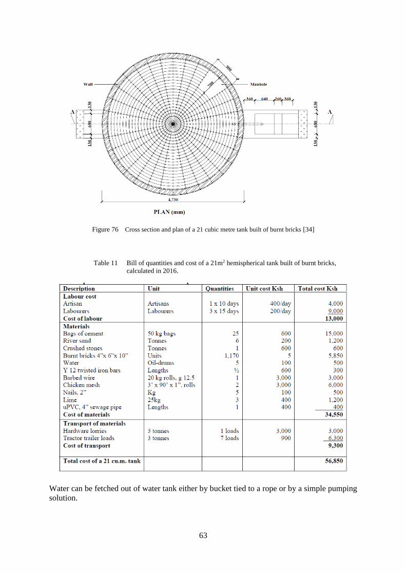
63
Figure 76 Cross section and plan of a 21 cubic metre tank built of burnt bricks [34]
Table 11 Bill of quantities and cost of a 21m2 hemispherical tank built of burnt bricks,
calculated in 2016.
Water can be fetched out of water tank either by bucket tied to a rope or by a simple pumping
solution.

64
4.4 Hemispherical water tank made of Ferro-cement
Excavation of hemispherical tank:
Figure 77 Excavation works [34]
Plastering:
The walls of soil are plastered with 3 cm thick coat of mortar. The procedure is to be completed
in one day. The mortar is mixed at proportions 1:3 [34].
Figure 78 Plastering the walls of soil [34]
Wired mesh and plastering:
The next day, when mortar is dry, wired mesh is applied and nailed to the walls. Another layer
of mortar and waterproof coating are applied afterwards. Curing of mortar might take up to
three weeks during which it is recommended to keep mortar wet and under the shade at all time
[34].

65
Figure 79 Wired mesh application [34]
Table 1 Bill of quantities for a 60m2 hemispherical tank built of ferro-cement, calculated
in 2016 [34]

66
4.5 Plastic water storage tank
The plastic water tanks do not allow any water leakage as long as they are not physically
damaged. They come in a variety of shapes and sizes and can reach up to 75000 litres although
anything over 5000 litres might be unreasonable due to its cost difficulty to transport. The
5000 litres tank in the example shown below, has a diameter 2175mm, height 1750mm, Inlet
Height 1630mm, and it weights 125kg [35].
Figure 80 5000 litres plastic water tank [35]
5 WATER TREATMENT BEFORE USAGE
Although rainwater is relatively clean, treatment before drinking and cooking is recommended
to prevent any possible diseases. Treatment might not be needed for washing and cleaning
purposes.
Rainwater treatment can be divided into two systems: Treatment at Point of Entry (POE) and
treatment at Point of Use (POU). POE is a system which treats water before entering the house
while POU will only treat water at the point of consume.
A small treatment system for each household could be implemented. The treatment process is
carried out in three steps.
The first step is sedimentation. This function is mostly carried out by the water tank
itself as all heavier particles eventually settle on the bottom of a tank.
Second step is filtration. Filtration is commonly used after sedimentation to further
reduce turbidity and remove pathogens. It is advised to use a simple biosand filter for
this step as it has a perfect quality to price ratio.
Then the most important process is disinfection. Four ways of disinfection will be
presented accordingly from the cheapest to most expensive.
o First method uses boiling water to kill most of the viruses. It is highly effective.
o Second is disinfection using chlorine, a simple and cost efficient method but
there will be changes to the taste and smell of water.
o Third method, using ozone disinfection, more expensive than previous method
but the changes in smell and taste are hardly noticeable.

67
o The fourth method is using UV disinfection, the least cost efficiency but does
not affect any water’s properties. The effectiveness of all four methods is
relatively similar.
5.1 Biosand filter
The biosand filter is an improvement upon traditional slow sand filters, specifically designed
for intermittent or household use. The filter is easy to use and can be manufactured anywhere
with use of local materials [36].
The filter container can be made of concrete, plastic or any other waterproof, rust proof and
non-toxic material. The most widely used version is concrete container, approximately 0.9
meters high and with a surface of 0.3 m2. The container is then further filled with layers of
filtering material. There is a standing water height of 5 cm above the sand layer, which is
maintained by adjusting the height of the outlet pipe. It is this feature that allows the formation
of a biofilm layer [36].
The operation process is simple. The water is poured into container form the top. Then the
water will slowly travel through the layers of sand and gravel. At the base of a filter, the water
is them collected in a pipe and drained though plastic piping out of the filter to be collected and
stored in a clean water container [36].

68
Figure 81 Biosand filter construction [37]
Lid: The lid should be tight. It prevents contamination and keeps out unwanted pests.
Reservoir: The top of the filter where water is poured in is called the reservoir. The
reservoir can hold about 12 litres, or 1 bucket of water.
Diffuser: The diffuser catches the water poured into the BSF. It can be a box or a plate.
It has small holes in it, so the water slowly drips through to the sand.
Standing Water: When the water stops flowing, there should be 5 cm of water on top
of the sand. This layer of water protects the top of the sand and the biolayer from the
force of the dripping water. The standing water also keeps the biolayer wet. The
biolayer will die if it dries out.
Filter Container: The container can be made out of concrete or plastic. It can be square
or round. It holds the sand, gravel and water.
Filtration Sand: The sand inside the filter is the most important part. The sand removes
most of the pathogens and dirt from the water. The sand must be prepared correctly for
the filter to work.
Biolayer: The biolayer is the top layer of sand (1-2 cm deep), where very small microbes
live that kill pathogens in the water.
Separation Gravel: The small gravel stops the sand from moving down and blocking
the outlet tube.
Drainage Gravel: The large gravel stops the small gravel from moving and blocking the
outlet tube. The large gravel is too big to get inside the outlet tube.
Outlet tube: Water that comes out of the outlet tube is safe to drink. The tube can be
made out of plastic or copper.
Safe Storage: You must have a clean safe water storage container to collect the water
as it flows out of the outlet tube [37].

69
Figure 82 Biosand filter proportions [37]
5.2 Boiling
Water boiling is one of the oldest and most commonly practiced household water treatment
method. For the treatment to happen, it is required to boil the water until the appearance of the
first big bubbles to ensure that it is pathogen free [38].
It is important to remember, that boiling only kills pathogens, so prior to boiling, water must
be settled (sedimentation process) and filtered (e.g. through biosand filter) as well [38].
If practiced correctly, boiling is one of the most effective water treatment methods to kill or
deactivate all classes of waterborne pathogens, including bacterial spores and protozoan cysts
that have shown resistance to chemical disinfection and viruses that are too small to be
mechanically removed by microfiltration [38].

70
Figure 83 Boiling outputs [38]
After boiling, water should be placed in a clean and tightly sealed container to prevent future
recontamination [38].
Despite its simplicity, boiling has its disadvantages. Boiling requires sufficient fuel supply (e.g.
wood, kerosene, electricity, gas, charcoal etc.), it does not remove chemical pollution (such as
arsenic). Also boiling water with high amount of calcium will be leaving white scales in the
container (boiling pot), which will need to be washed after every use [38].
5.3 Chlorination
The disinfection of drinking water by adding chlorine is called chlorination. Water disinfection
by chlorination was massively introduced in the early twentieth century. Chlorine is not only
destroying harmful microorganisms but also reduces the amount of iron, manganese and
hydrogen sulphide in water. Chemical disinfection using chlorine has the benefits of being
relatively quick, simple, and cheap and allows a residual amount of chlorine to remain in the
water to provide some protection against recontamination.
Today, chlorination is used to treat most of drinking water in the world since it is easy,
inexpensive and reliable. One should however remember that chlorine causes danger to human
health, if not properly handled or dosed wrongly. Therefore, proper training must be carried
on.
Chlorination can be achieved either by using liquefied chlorine gas or sodium hypochlorite
solution or calcium hypochlorite granules or on-site chlorine generators.
International agencies have been promoting chlorination at household level as effective and
simple solution for drinking water treatment in developing countries. The different radicals and
ions formed during chlorination destroy many bacteria and viruses, but also oxidise some
organic matter, dissolve colours and destroy chloramines, toxic products derived from
ammonia. It takes about 30 minutes to do this work and make water safe to drink. The correct
amount of chlorine solution must be used. If the concentration of chlorine is inadequate, the
solution may fail to destroy all the harmful micro-organisms and if in excess, health may be
adversely affected. According to WHO guidelines, the FRC (Free Residual Chlorine)
concentration in drinking water should be between 0.2 to 0.5 mg/L. Turbidity may also protect
microorganisms from disinfection, thus sedimentation and filtration (e.g. biosand filter) is
required beforehand [39].
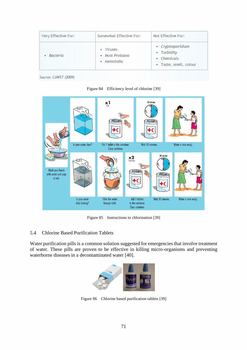
71
Figure 84 Efficiency level of chlorine [39]
Figure 85 Instructions to chlorination [39]
5.4 Chlorine Based Purification Tablets
Water purification pills is a common solution suggested for emergencies that involve treatment
of water. These pills are proven to be effective in killing micro-organisms and preventing
waterborne diseases in a decontaminated water [40].
Figure 86 Chlorine based purification tablets [39]

72
In order to combat the challenge of decontamination if the water is to be stored for a longer
period of time, one needs to carefully choose the containers which are going to be used for
storage of treated water. These containers must be tightly sealed and should be cleaned in
advance [40].
Water purification tablets usually have a lifespan up to five-years of shelf life. Yet, in order to
preserve their effectiveness, instructions that can be found on the back of the package must be
followed. In general though, all tablet products should be secured from exposure to extreme
temperatures, high humidity and air moisture. Once opened and exposed, the product should
not be kept for more than a year for it to keep its level of performance [40].
Figure 87 Chlorine tablet reaction in water [40]
“Instructions on how to use Chlorine based purification tablets [40]:
1. Slackly cap the water container after adding the tablets in harmony with the product’s
labeling
2. Wait for five to ten minutes then jiggle the container rapidly so that a small quantity of
the solution leaks out to rinse the lid and lip of the container
3. Lastly, tighten and squeeze the cap and postpone the sipping for at least 30 minutes”
Even though the exact time needed for purification varies to some extend depending on the
quality of water, its quantity and its turbulence, almost all products on the market label their
demands for a 30-minute waiting phase before drinking the water that was treated. This half an
hour treatment period guarantees an adequate time for the tablet to deactivate target
microorganisms and make the water suitable for drinking [40].
Purification tablets can be found at the pharmacies. Each tablet has a capacity to purify up to
20 liters if water [40].

73
5.5 WATA Chlorine Generation Device
WATASOL is an approach developed by Antenna Technologies, which produces chlorine
solution through the electrolysis of salted water. The resulting solution is can be used for
purifying water (1L of chlorine per 4000L of contaminated water) or disinfection of food
preparation materials, premises and other equipment [41].
Figure 88 Solar powered WATA device [41]

74

75
Figure 89 Step-by-step work process of WATASOL device [41]
The device requires water, salt and electricity. When immersed, and connected to a reliable
source of electricity, a process of electrolysis takes place, converting the saline solution
(sodium chloride) - with 25 g of salt per litre - into active chlorine (sodium hypochlorite) at
6g/L. Resulting solution can be added in small portions (5mL of chlorine per 20L of
contaminated water) into contaminated water [41].
Raw chlorine concentrate can also be used as a disinfectant. In diluted form, it can be used for
cleaning latrines, disinfecting kitchen utensils and surfaces, etc [41].
The WATASOL device has also potential to support a small privately owned local business
[41]. If the initial (purchasing) costs are not taken into account, the running costs of this system
are fairly low.
It must be kept in mind however that active chlorine is flammable and, thus, must be contained
and stored in closed and opaque recipients and kept in the shade. Under these conditions, the
active chlorine concentrate can be conserved over four weeks without any loss in its efficiency
[41].
It is important to use only clear water both for the process of electrolysis and for the water that
is about to be treated. Thus, before applying WATASOL, the water must firstly undergo
sedimentation process and filtration process. Chlorination cannot be guaranteed if the water
has a high level of turbidity [41].
In order to preserve WATASOL device, it is advised to rinse it off after each procedure with
clear water. With time, calcareous deposits form on the electrodes. The frequency of which this

76
deposits need to be cleaned depends on the water hardness, it is recommended to do it after
about 150 hours of functioning.
Properly used, well maintained and carefully stored after each use, WATA devices are
guaranteed to operate for at least 20 000 hours of operation (4,5 years on the basis of 12 hours
use per day) [41].
Figure 90 Local business that operates by selling WATASOL purified water [41]
Advantages of WATASOL [41]:
Low cost of operation
Supports local production (avoid most storage and transportation problems and
environment impacts)
Generation of income for local communities (e.g. water kiosks)
Easy to use and operate
Solar versions available for use in rural areas (powered by small movable solar panels)
Disinfectant can be used for a large range of applications (e.g. cleaning latrines,
disinfecting kitchen utensils and surfaces, washing rough fruits and vegetables,
disinfecting laboratory equipment, wounds etc.)
Quality control is possible at every stage of production and use.
Disadvantages of WATASOL [41]:
Requires a high one-time investment to purchase the device
Only clear water can be used to produce WATA solution and the solution is effective
to treat only clean water (thus sedimentation and filtration processes are required)
Requires electricity (has an option for solar powered device)
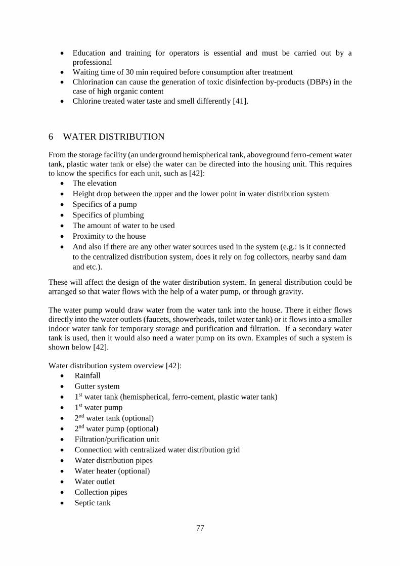
77
Education and training for operators is essential and must be carried out by a
professional
Waiting time of 30 min required before consumption after treatment
Chlorination can cause the generation of toxic disinfection by-products (DBPs) in the
case of high organic content
Chlorine treated water taste and smell differently [41].
6 WATER DISTRIBUTION
From the storage facility (an underground hemispherical tank, aboveground ferro-cement water
tank, plastic water tank or else) the water can be directed into the housing unit. This requires
to know the specifics for each unit, such as [42]:
The elevation
Height drop between the upper and the lower point in water distribution system
Specifics of a pump
Specifics of plumbing
The amount of water to be used
Proximity to the house
And also if there are any other water sources used in the system (e.g.: is it connected
to the centralized distribution system, does it rely on fog collectors, nearby sand dam
and etc.).
These will affect the design of the water distribution system. In general distribution could be
arranged so that water flows with the help of a water pump, or through gravity.
The water pump would draw water from the water tank into the house. There it either flows
directly into the water outlets (faucets, showerheads, toilet water tank) or it flows into a smaller
indoor water tank for temporary storage and purification and filtration. If a secondary water
tank is used, then it would also need a water pump on its own. Examples of such a system is
shown below [42].
Water distribution system overview [42]:
Rainfall
Gutter system
1st water tank (hemispherical, ferro-cement, plastic water tank)
1st water pump
2nd water tank (optional)
2nd water pump (optional)
Filtration/purification unit
Connection with centralized water distribution grid
Water distribution pipes
Water heater (optional)
Water outlet
Collection pipes
Septic tank

78
Water discharge.
Figures below give a visual representation of such system.
Figure 91 Water distribution system with a low flush toilet [42]

79
Figure 92 Water distribution system with a dry toilet option [42]
Rainfall:
It is the main source of water for an off-grid water system. More information regarding the
rainfall and a precipitation level in Marsabit County can be found in the Baseline Report.
Gutter system:
Acts as a conveyance system for the water harvested during the rainfall season.
1st water tank:
Acts as a permanent storage facility, where harvested water awaits its turn to be used whenever
it is needed.
1st water pump:
1st water pump draws the water from the water tank into either a temporary storage facility
(smaller indoor water tank) or directly into the water outlets, such as: water faucets,
showerheads, toilet water tanks and etc [42].
80
2nd water tank (optional):
Secondary water tank serves as a temporary storage facility before the water is directed into
the water outlets. Secondary water tanks are usually much smaller then main water tanks and
only need to hold as much water as needed on an average day (240 litres for a family of 8). A
design that includes secondary water tank allows for a better inspection of water as well as its
filtration and purification [42].
Filtration/Purification unit:
A water pump will usually push the water through a filtration/purification unit on its way to
the water outlets.
Note, that the filter is plumbed in after the second water pump, so water is pushed through it.
Once filtered, water flows to the plumbed micro house water system.
Note, that if water is being treated manually via Chlorine based purification tablets, then no
filtration/purification unit is needed [42].
Connection with centralized water distribution grid:
Despite having the access to rainwater and the means to collect it, it is, nevertheless,
recommended to have an access to centralized water distribution grid. It will ease up the need
for water in dry seasons and will ensure that inhabitants will never be left without water. Such
connection must be done by a professional plumber.
Water heater (optional):
A water heater can be integrated in the system. Any kind of electrical heater (boiler) will be
suitable.
6.1 Water pump
Pumps are needed whenever there is either an insufficient difference in water levels in gravity
drawn systems or a negative difference in water levels, where gravity works against a desirable
outcome. Pumps are used to transfer water from point A to point B with pressure to overcome
this level difference and resistance along its path. A pump can increase the uses of the water-
harvesting system and is required when consistent pressure is needed. Pump selection is based
on two prime factors: water flow and total head that pump is required to supply [43].
Flow is the rate at which water travels through a pipe and often is measured in litres per
minute (l/s).
Total head is a description of the energy required to move the water and is typically
expressed in kPa.

81
Figure 93 A typical pump [44]
Pump types:
Pumps can be generally divided into two major categories: positive displacement pumps and
dynamic pumps.
Positive displacement pumps operate by mechanically moving water by means of the
action of a gear or piston and are able to produce high heads, but relatively low flows.
They are generally used in hydraulic systems and in a number of specialty applications.
Typical positive displacement pumps are piston and rotary pumps [44].
Dynamic pumps provide a continuous flow by developing a high fluid velocity and are
able to produce high flows, but relatively lower heads. They are used to satisfy most
general pumping requirements and typically require less maintenance than
displacement pumps. Typical dynamic pumps include centrifugal and jet pumps [44].

82
Figure 94 Pump structure [44]
A centrifugal pump is suitable for most water-harvesting applications because of its relative
simplicity, range of head and flows, and relative low cost. A centrifugal pump consists of a
motor, pump casing, and impeller as shown in Figure above. A pump casting holds the impeller
channels water to and from the impeller. The impeller is a rotating vane structure that draws
water into the pump casing, transfers energy to the water, and discharges it from the pump
casing. The energy needed to rotate the impeller is supplied via a motor [44].
Calculation of water flow:
The flow needed for a pump is determined by addition of flows of all water outlets, such as
toilets (low-flush toilets), showerheads, water faucets, sprinklers etc., that may draw water from
the water tank at the same time. Specific flows for many devices can be found in the product
descriptions and should be used in calculations when available [44].
Calculation of a Total Head:
The formula that determines Total Head is presented below:
TDH = hp + he + hf where:
hp is the operating head (pressure) required by an outlet (water faucet, showerhead, toilet
etc.)
is the elevation difference between a pump and an outlet
is the friction loss in system (meters).
he h2 h1
hf

83
Figure 95 Graphic representation of terms stated in formula above [44]
Pressure Hp:
Pressure requirements are set by the products used and can be typically found in the product
description. The pressure must be set at an adequate level: not too high and not too low. If the
pressure is too low, the pump may not provide an adequate flow to operate the device. Contrary
to low pressure, high pressure might damage seals and other plumbing equipment [44].
Elevation HE:
Elevation is set as a difference between the upper point of water distribution system (the water
outlet) and its lower point (the level of pump intake (not the pump itself)) [44].
Friction HF:
Friction accounts for energy losses associated with moving water due to friction with the pipe
walls, elbows, valves and other fittings [44].
Hf = f (L/D) x (v^2/2g)
where:
hf = head loss (m)
f = friction factor
L = length of pipe work (m)
d = inner diameter of pipe work (m)
v = velocity of fluid (m/s)
g = acceleration due to gravity (m/s²)
Pump selection:
A good supplementary tool for pump selection is a “Pump curve”. Typically, such curve can
be found in the product’s description [44].

84
Figure 96 Example of pump curves with different impeller diameters [45].
6.2 Water distribution pipes
A water pipe is any pipe or tube designed to transport water to consumers. The varieties include
large diameter centralized distribution pipes, which supply entire towns, smaller branch lines
that supply either a street or a larger district, or small diameter pipes that connect individual
houses to the main grid. Pipes are commonly made of cast iron, polyvinyl chloride (PVC),
copper and steel [46].
Currently metallic pipes, while still being a viable option, experience decline in popularity
worldwide. It is related to their inefficiency in coping with corrosion. Corroded metal pipes are
harmful for user’s health. PVC pipes, on another hand, are non-corrosive, extremely light and
thus more easily applicable. The only significant downside of PVC pipes is that they are prone
to physical damage if exposed over ground and become brittle when exposed to ultraviolet light
for a prolonged time. In addition to the problems associated with the expansion and contraction
of PVC, the material will soften and deform if exposed to temperatures over 65 °C [46].
Figure 97 Water distribution pipes [46]

85
Installation of pipes make up a big part of total cost of a project and following factors must be
considered before installation begins [46]:
Weight of a pipe – Lightweight pipes are easier to handle.
Ease of assembling – Push-on joints can be assembled very fast
Pipe strength – Extra costs can be avoided by choosing durable pipes that do not require
any additional bedding for themselves [46].
6.3 Water distribution pipes maintenance plan
Most of water and sanitation projects experience their main problems with maintenance and
operation. Different projects around the world demonstrate how the newly built infrastructure
deteriorates over time. Operation and maintenance plan (O&M) refers to all activities needed
to run a water supply and sanitation scheme. The goal of O&M plan is to ensure efficiency,
effectiveness and sustainability of water supply [47].
“Maintenance activities can be categorized to:
Preventive maintenance: includes work that is planned and carried out on a regular
basis to maintain and keep the infrastructure in good condition, such as network
inspection, flushing of the well, cleaning and greasing of mechanical parts and
replacement of items with a limited lifespan. It sometimes also includes minor repairs
and replacement as dictated by the routine examinations.
Corrective maintenance: replacing or repairing something that was done incorrectly
or that needs to be changed; an example is the reallocation of a pipe route or
replacement of a faulty pump.
Reactive maintenance: a reaction to a crisis or public complaints; it normally occurs
as a result of failures and the malfunctioning or breakdown of equipment. In time
preventive and corrective maintenance will effectively reduce the chance of crisis
occurrence [47]”.
It is important to engage the end users in operation and maintenance as it will raise their level
of awareness and responsibility for the system. Thus, an “owner’s manual” prepared by the
contractor and engineer must be introduced. This should give a schedule and procedures for
maintenance for users [47].

86
Figure 98 An example of a maintenance plan [47]
6.4 Recontamination prevention and leakage control
Recontamination of an, otherwise, already treated water is a common problem in many
countries around the world. Especially it is common where distribution network is not properly
maintained and is thrown in neglect. There are several main sources for recontamination, such
as leaching or microbiological growth inside the pipes [48].
Microbiological Growth and Regrowth [48]:
An excessive microbial growth along the interior walls of drinking water distribution pipes is
a common problem. The development of an organic bacterial community, also commonly
known as biofilm, is composed of microorganisms and their secretions. It is present in almost
every water distribution system, the problem arises when it grows uncontrollably. Then it may
pose a threat to public health.
Chlorination successfully deals with this issue. Chlorinating the water supply (residual
chlorination) is the method usually used to control the growth of a biofilm (bacterial
community). In most cases, maintaining the normal amount of chlorine used to disinfect
drinking water will control this problem (WQHC 2012).
According to WHO guidelines, the FRC (Free Residual Chlorine) concentration in drinking
water should be between 0.2 to 0.5 mg/L (WHO 2006).
Leaching [48] :
All materials when placed under water as is the case for water distribution pipes, undergo
reactions that introduce substances to the water via a process known as "leaching". Pipes,
fittings, linings, and other materials used in joining or sealing pipes leach at least some
substances to water through corrosion, dissolution, diffusion, or detachment. Most of leached
material is harmless and should not raise any concern for health due to its non-toxicity and only
at trace levels of matter, yet the taste and the smell might raise some complaints.

87
Lead poisoning [48]:
Water is rarely found to contain lead in it, but it is worth to make sure that no lead pipes are
used in construction. Lead poisoning is a serious and life threatening condition. It occurs when
lead builds up in the body. Lead poisoning usually occurs over a period of months or years. It
can cause severe mental and physical impairment [48] [49].
Leakage and leak detection
All piped networks are subjects to leaks and, thus, must be controlled and inspected for that.
Leakage control is a regular activity and can be included in a regular maintenance plan) [50].
Aging material and poorly done workmanship, poor quality materials and high pressures in the
system – all these factors may contribute to loss of water resource. The points of leakage not
only allow water to be lost, but may also allow contaminants to enter the system, thus spawning
a bacterial growth. Leak detection aims to locate and repair small defects in pipes before they
start posing significant threat to overall system and large amounts of water are lost as a result
of it [50].
One way to detect smaller holes and cavities in distribution pipes is to look for the sound of it.
Pressurized water, when exits the system through a small crack creates sound waves in the
audible range. The sound transmitted by the pipe wall can be heard by listening at the hydrants,
main valves, and curb valves. The nature of the sound emitted by escaping water depends on
water pressure in the main, pipe material and size, soil conditions, and configuration of the
opening [50].
Pipes and joints are commonly repaired by placing an external cover over the leak. Notice, that
repairing material should be of the same nature as a maternal material (the material of the pipe
itself). Fixing sleeves and cylindrical halves are then applied over the batch for a better
connection [50].
7 WATER USAGE
Since the water resource is limited in Marsabit County, the water usage needs to be reduced
via a number of products and simple techniques that would not pose any inconvenience on the
user.
To save up water and improve the quality of living, the following could be done [51]:
Install a dry toilet, composting toilet or low flush toilet. These use no water or very little
water.
Use foaming soap. This allows users to only user water for rinsing instead of for soaping
up and rinsing.
Install water tap aerators or more efficient fixtures. Water tap aerators can save up to
80% of you water use in the kitchen and there are even some technologies that have a
higher efficiency.
Take short showers and collect and use the water from you shower for your garden, but
firstly check that soaps and detergents in the water will not harm garden plants.
Replace the shower head with a water-efficient model. Aerated shower heads can
increase the pressure and reduce water usage.
Consider reusing greywater from the laundry on the garden.

88
Avoid washing clothes unnecessarily.
When washing dishes, do not rinse them under a running tap. If you have two sinks, fill
the second one with rinsing water. If you have only one sink, stack washed dishes in a
dish rack and rinse them with a pan of hot water.
Apply washing up liquid on dry surfaces of your kitchenware before opening the tap.
Use washing up liquid sparingly as this will reduce the amount of rinsing required when
washing dishes by hand.
Capture excess water in a container while running the tap. This water can be used in
the garden.
Avoid keeping water running when washing fruits and vegetables. Washing them in a
bowl conserves water.
Organize and compost kitchen wastes (organic matter).
Mulch your garden. Mulch is a layer of material spread on top of the soil to conserve
moisture, discourage the growth of weeds and even out soil temperatures. It can keep
up to 70% more water in the soil.
Use drip irrigation systems instead of sprinklers.
It is better to water plants in the morning when the temperature is lower and less
evaporation occurs.
By following these simple instructions and turning them into a habit one can substantially lower
his/her level of water consumption [51].
7.1 Foaming soap making
Foaming soap is a low budget easy to produce product that helps to preserve the environment,
saves money on purchasing soaps and requires less water to rinse off [52].
For foaming soap making you need [52]:
1. Empty soap dispenser (any would work) with a sprinkler on it.
2. 0.5 litre of clean water.
3. 3 tablespoons of normal liquid soap
First, fill up the dispenser with water, then add there 3 tablespoons of soap, seal it with cap
tightly and shake for better mixture. It is done. Now, push the sprinkler to release the soap and
apply in on your hands or face [52].

89
Figure 99 Homemade foaming soap [52]
7.2 Water tap and showerhead aerators
Installing low-flow shower heads and faucet aerators is one of the most effective water
conservation methods you can do for your home. Inexpensive and simple to install, low-flow
shower heads and faucet aerators can reduce your home water consumption as much as 75%
[53].
Aerating faucets and showerheads mix air into the water stream. This maintains steady pressure
so the flow has an even, full shower spray. Though in a shower, because air is mixed in with
the water, the water temperature can cool down a bit towards the floor. There is no sacrifice
in water pressure and rinse-ability of user. There are also adjustable models on the market with
flow controllers on them that can change their behaviour depending on one’s needs. If one
needs, for example, to fill up a bucket of water, it can provide a fast and steady flow of water
and if one needs to rinse kitchenware or rinse fruits and vegetables it can go into an aerating
mode while keeping the same pressure [53].

90
Figure 100 Kickstarter project: Nozzle aerator that saves up to 98% of water [54]
Low-flow faucet aerators usually cost $5 -$10. Low-flow shower heads range from $8 - $50
depending on features such as flow adjusting dials and designer styling. Prices may vary based
on location [53].
8 WASTEWATER TREATMENT AND REUSE
Wastewater treatment is described in more details in technical notes regarding sanitation.
However, a brief description of how to treat it and use it is given here.
Since water is scarce in Marsabit County, wastewater reuse is a sensible suggestion. The
recycled water will not be used for cooking nor drinking but can be used for washing purposes,
irrigation, etc. The treated wastewater may also be released back to the environment.
Simple off-grid on-site wastewater treatment can be arranged with relatively low investments.
These simple methods can be implemented individually for each household or for multiple
households.
There are 2 types of domestic wastewater, black water and grey water. Grey water is water
coming from shower/bath, washing clothes water and water from kitchen sink. Black water is
water flushed down from toilet that contains faeces, urine and bacteria and thus requires more
treatment. Dry toilet system, if implemented, would avoid the generation of black water. Grey
water on the other hand can be relatively clean. Contaminants are usually dirt, food and
washing chemicals (hand soap, shampoo, detergent) which are dissolvable and easy treat.
However, if both greywater and blackwater are generated, it is recommended that the
wastewater is treated in a septic tank. If blackwater is not generated, the wastewater can be
treated and used through simpler and more cost effective methods, e.g. the greywater towers.
However, when having babies in a house, also gray waters might include faecal pathogens due

91
to ‘bottom’ washing. If so, treatment or longer storage time of wastewater is required before
reusage.
8.1 Septic tank
A septic tank is a watertight chamber made of concrete, fiberglass, PVC or plastic, through
which greywater and blackwater flows for primary treatment. Although settling and anaerobic
processes reduce solids and organics, the treatment is still only moderate [55].
The septic tank works so that liquid flows through the tank and heavy particles sink to the
bottom. Over time, solids settling to the bottom are degrading anaerobically. However, the rate
of accumulation is faster than the rate of decomposition, and the accumulated sludge and scum
must be periodically removed [55].
Septic tank should have at least two chambers. The first chamber should be the size of at least
50% of the total length, and when there are only two chambers, it should be two thirds of the
total length. Most of the solids settle down in the first chamber. The separation between the
chambers, is to prevent scum and solids from escaping with the wastewater. The T-shaped
outlet pipe further reduces the scum and solids that are discharged [55].
Accessibility to all chambers (through access ports) is necessary for maintenance. Septic tanks
should be vented for controlled release of odorous and potentially harmful gases. Design of a
septic tank depends on the number of users, the amount of water used per capita, the average
annual temperature, the desludging frequency and the characteristics of the wastewater. The
retention time should be 48 hours to achieve moderate treatment [55].
This technology is most commonly applied at the household level. A bigger, multi-chamber
septic tanks can be designed for groups of houses and/ or public buildings (e.g., schools).
Figure 1 Principal septic tank scheme [55]

92
Under normal conditions, users do not come in contact with the greywater. Generally the waste
water, the sludge and the scum must be handled with care as they contain high levels of
pathogenic organisms. Users need to be careful when opening the tank because noxious and
flammable gases may be released [55].
Care should be taken not to discharge harsh chemicals into the septic tank. Scum and sludge
levels need to be monitored to ensure that the tank is functioning well. Generally based on their
size, septic tanks should be emptied every 2 to 5 years. Septic tanks must be checked from time
to time to ensure that they are watertight [55].
8.2 Greywater towers
Greywater towers are circular bags that are filled with soil, ash or compost mixture with a
gravel column at the center. It is used to treat and reuse greywater. Vegetables are planted in
holes cut in the sides of the bag and each day the available greywater from a households is
poured directly on the gravel column making vegetables grow [56].
Greywater towers are great offer for the areas with lack of water resources. They are a low-
cost solution that allows the reuse of greywater with application of nutrient content for
gardening and food purposes. Greywater towers are cylindrical and made from simple plastic
bags or clothes, reinforced with wooden poles, filled with a soil mixture (soil, ash and/or
compost or vermicompost) and anchored into the soil [56]. Vegetables are then grown in holes
cut in bag sides. Each day, the available greywater is poured into the bag. Greywater from bath,
laundry or kitchen contains nutrients on which vegetables grow successfully [56].
Figure 1 Step-by-step instruction to construct a greywater tower [57]
To construct a greywater tower, a circle should be marked out on the ground with a diameter
of around 80 cm. The bottom layer of the tower should be dug out and the wooden side poles
need to be firmly planted into the ground. A shade cloth is then wrapped around the poles and
the resulting cylinder will be filled with gravel in the middle and the soil mix all around. The
backfill should be well mixed before applying it. A bucket with the bottom removed can be

93
placed at the bottom in the middle of the tower to increase stability and improve the flow
regime. Small stones should be packed in the bucket to increase weight and to prevent fast flow
of the water through the bucket and to achieve even water distribution. As the bucket is filled
with stones, it is backfilled with the soil mixture. After that, the bucket can be removed (and
reused), leaving the stones in position. The soil should be humid but not too wet, when packing
the tower. The soil should be distributed evenly so that water can flow through. For each soil
layer placing the bucket, filling it with stones, backfilling it and then removing the bucket
process has to be repeated up to the top layer of the greywater tower (around 1 m in height)
[56].
One of the biggest advantages of the method is that little labour for construction and little
operation and maintenance is required. Once people get familiar with the towers, they are easily
maintained. The towers can be positioned at the back door so that it is easy to pour the
wastewater into the tower. [56]
It can be difficult to predict how much water is required, and the necessary experience will
usually come over some time. In the beginning it is recommended to apply about 20 L per day
and attune it according to the exact water demand. If water forms a puddle around the bottom
of the tower it means that too much water is being applied. A possible solution for this problem
would be to make a second tower [56].
Greywater towers are best for leafy crops such as spinach. Ideally, the planting holes should
not be one above the other but staggered diagonally, providing more space for root
development. Different crops which use the soil in a complementary way should be grown to
facilitate biological control of disease and pests. For example tomatoes and onions can be
planted on the top of the tower. Garlic and onions are also useful to prevent plant diseases and
pests. If crops require trellises, this can be provided by extending the vertical uprights and
joining them with wire or string [56].
8.3 Greywater uses for irrigation
The treated wastewater from the septic tank could then be used for irrigation purposes [58].
Figure 1 Greywater used for irrigation [58]

94
A method called drip irrigation system for example, allows to save substantial amount of water
through efficient rationing of it. Instead of typical, for rural areas, showering technique where
one takes a bucket of water and pours it in a general direction of a plant, here through a system
of elastic tubes (hoses) the water travels directly to the plants and gets into the soil through a
series of small holes along the tube. This way the plant will need significantly less water for
survival and growth. If the tank is placed as shown in figure below, the gravity force will push
the water down the stream, which means this system requires minimum maintenance and is
easy to use. It will also alleviate the pressure for farmers, since they will have more free time
during the day for other chores [59].
Figure 2 Drip irrigation system [59]

95
Bibliography
[1] ”Organization of American States,” [Online]. Available:
https://www.oas.org/dsd/publications/unit/oea59e/ch10.htm. [Haettu 4 August 2018].
[2] "Rainwater harvesting," 2011. [Online]. Available:
http://www.climatetechwiki.org/content/rainwater-harvesting. [Accessed 5 December
2016].
[3] "Architectural Styles, Part 1 of 2," ASHI Reporter, p. 4, 2013.
[4] "How To Make Unbuildable Land Buildable with Rainwater Collection.," 2011. [Online].
Available: http://www.tinyhousedesign.com/how-to-make-unbuildable-land-buildable-
rainwater-collection/. [Accessed 5 December 2016].
[5] "Downspout first flush diverters," 2014. [Online]. Available:
http://rainharvesting.com/product/downsput-first-flush-diverters/. [Accessed 5 December
2016].
[6] "Gutter options superb downspout screens," 2015. [Online]. Available:
http://www.neiltortorella.com/gutter-options/superb-gutter-options-15-gutter-downspout-
screens/. [Accessed 5 December 2016].
[7] "Household water storage," Waterlines, vol. Technical Brief No.1.
[8] "How to Make Bamboo Rain Gutters," 2014. [Online]. Available:
https://www.guaduabamboo.com/working-with-bamboo/joining-bamboo. [Accessed 5
December 2016].
[9] ”Bamboo Gutter or Waterfeature Channel,” 7 July 2015. [Online]. Available:
http://www.japangarden.co.uk/Bamboo-Gutter-or-Waterfeature-Channel-ex-100mm-poles-
pr-3143.html. [Haettu 18 July 2017].
[10] ”Bamboo joints and joinery techniques,” [Online]. Available:
https://www.guaduabamboo.com/working-with-bamboo/joining-bamboo. [Haettu 4 August
2018].
[11] ”Guadua Bamboo,” [Online]. Available: https://www.guaduabamboo.com/working-with-
bamboo/splitting-bamboo. [Haettu 4 August 2018].
[12] ”Bamboo Import Europe,” [Online]. Available:
https://www.bambooimport.com/en/blog/how-to-make-bamboo-rain-gutters. [Haettu 4
August 2018].
[13] "A Simple Introduction to Press Brakes.," 2016. [Online]. Available:
https://www.linkedin.com/pulse/simple-introduction-press-brakes-andy-kamashian.
[Accessed 7 December 2016].
[14] "V-shaped roof gutter / steel / PVC," WeatherFAST Ltd, 15 June 2015. [Online]. Available:
http://www.archiexpo.com/prod/weatherfast-ltd/product-126031-1590602.html. [Accessed
26 July 2017].
[15] Rutland, "Rain Gutter Styles - Guttering Profiles Types.," Rutland web site, 2011. [Online].
Available: http://rutlandguttersupply.com/rain-gutter-styles-guttering-profiles-types/.
[Accessed 5 December 2016].
[16] ”FRP Rain Water Gutters,” Dura Plast Solutions, 1 July 2015. [Online]. Available:
http://www.duraplastsolutions.com/frp-rain-water-gutters.html. [Haettu 26 July 2017].
[17] "Half Round Aluminum Gutters," Guttersupply.com, 2016. [Online]. Available:
https://www.guttersupply.com/p-halfround.gstml. [Accessed 5 December 2016].

96
[18] "Advantages of Plastic Gutters," [Online]. Available:
https://www.doityourself.com/stry/advantages-of-plastic-gutters. [Accessed 9 August
2018].
[19] "Gutter pipes," Metrogroup.co.ke, 2013. [Online]. Available:
http://www.metrogroup.co.ke/index.php/products/item/383-gutter-pipes-profile. [Accessed
5 December 2016].
[20] "Fog harvesting," Climatetechwiki.org, 2011. [Online]. Available:
http://www.climatetechwiki.org/content/fog-harvesting. [Accessed 5 December 2016].
[21] "Rural Kenya harvests water from fog," Trust.org, 2013. [Online]. [Accessed 7 December
2016].
[22] "Fog catchers and how to make your own," Watersustainabilityandfogwater.wordpress.com,
2014. [Online]. Available: https://watersustainabilityandfogwater.wordpress.com/fog-
catchers-and-how-to-make-your-own/. [Accessed 7 December 2016].
[23] L. Cooke, "World’s largest fog harvester produces water from thin air in the Moroccan
desert," Dar Si Hamad, 27 March 2016. [Online]. Available: http://inhabitat.com/worlds-
largest-fog-harvester-produces-water-from-thin-air-in-the-moroccan-desert/. [Accessed 25
July 2017].
[24] L. Borst ja S. A. de Haas, ”Hydrology of Sand Storage Dams, A case study in the Kiindu
catchment, Kituï District, Kenya. Master thesis,” Vrije Universiteit, Amsterdam, 2006.
[25] Rain Foundation, ”Rainwater Harvesting Implementation Network: A practical guide to sand
dam implementation (Water supply through local structures as adaptation to clmate
change),” 2011.
[26] C. Gijbertsen, ”A study to upscaling of the principle and sediment transport processes behind
sand storage dams, Kituï District, Kenya,” Vrije Universiteit, Amsterdam, 2007.
[27] E. Nissen-Petersen, Water from Dry Riverbeds, Danish International Development
Assistance (Danida), 2006.
[28] J. N. Munyao, J. M. Munywoki, M. I. Kitema, D. N. Kithuku, J. M. Munguti ja S. Mutiso,
”Kituï Sand Dams: Construction and Operation,” SASOL Foundation, 2004.
[29] ”Understanding the Hydrology of (Kituï) sand dams: Mission report,” 2005.
[30] "15 Design of Sand Dams," MInistry of Environment, Water and Natural Resources, Kenya,
10 June 2015. [Online]. Available: http://design-of-small-dams.appspot.com/structures/.
[Accessed 12 July 2017].
[31] ”Hygiene Promotion, Thematic Overview Paper 1,” 2005.
[32] H. Gessesse and H. Nega, "Chapter 6 - Managing water," in Managing Land: A practical
guidebook for development agents in Ethiopia, Nairobi, Regional Land Management Unit
(RELMA in ICRAF), 2005, pp. 171-173.
[33] "Ferrocement Reservoir Manual," Ferrocement.com, 2007. [Online]. Available:
http://ferrocement.com/tankBook/indici.en.html. [Accessed 7 December 2016].
[34] E. Nissen-Petersen, "Water from Roads: A handbook for technicians and farmers on
harvesting rainwater from roads," ASAL Con-sultants Ltd. for the Danish International
Development Assistance (Danida) in Kenya, Nairobi, 2006.
[35] "R5000 Litre Squat Rainwater Tank," Watertankfactory.com.au, 2012. [Online]. Available:
https://www.watertankfactory.com.au/types/round-water-tanks/. [Accessed 12 December
2016].

97
[36] "Biosand Filter," Sswm.info, 2010. [Online]. Available:
http://www.sswm.info/category/implementation-tools/water-purification/hardware/point-
use-water-treatment/bio-sand-filtrat. [Accessed 12 December 2016].
[37] "Biosand Filter Construction Manual," Centre for Affordable Water and Sanitation
Technology, pp. 4-8, 2012.
[38] "Boiling," Sswm.info, 2010. [Online]. Available:
http://www.sswm.info/category/implementation-tools/water-purification/hardware/point-
use-water-treatment/boiling. [Accessed 12 December 2016].
[39] "Chlorination," Sswm.info, 2010. [Online]. Available:
http://www.sswm.info/category/implementation-tools/water-purification/hardware/point-
use-water-treatment/chlorination. [Accessed 12 December 2016].
[40] "Ultimate Guide to Water Purification Tablets," All-about-water-filters.com, 2015. [Online].
Available: http://all-about-water-filters.com/ultimate-guide-to-water-purification-tablets/.
[Accessed 12 December 2016].
[41] "WATASOL," Sswm.info, 2010. [Online]. Available:
http://www.sswm.info/es/category/implementation-tools/water-
purification/hardware/point-use-water-treatment/watasol. [Accessed 12 December 2016].
[42] Microshowcase.com, 2014. [Online]. Available:
http://microshowcase.com/microtech/offgridwater/. [Haettu 21 December 2016].
[43] B. Stauffer and D. Spuhler, "Pumping Stations," Sswm.info, 2012. [Online]. Available:
http://www.sswm.info/category/implementation-tools/water-distribution/hardware/water-
distribution-networks/pumping-statio. [Accessed 22 December 2016].
[44] M. P. Jones and W. F. Hunt, "URBAN Waterways: Choosing a Pump for Rainwater
Harvesting," North Carolina Cooperative Extension Service, 2006.
[45] B. Yiasoumi, ”Selecting an irrigation pump,” Dpi.nsw.gov.au, 2016. [Online]. Available:
http://www.dpi.nsw.gov.au/land-and-water/water/irrigation/systems/selecting. [Haettu 22
December 2016].
[46] E. Gur ja D. Spuhler, ”Water Distribution Pipes,” Sswm.info, 2012. [Online]. Available:
http://www.sswm.info/sites/default/files/reference_attachments/GONU%202009%20Techn
ical%20Guidelines%20for%20the%20Construction%20and%20Management%20of%20Dr
inking%20Water%20Distribution%20Networks.pdf. [Haettu 22 December 2016].
[47] "Operation and Maintenance," Sswm.info, 2010. [Online]. Available:
http://www.sswm.info/category/planning-process-tools/ensuring-sustainability/tools-
ensure-sustainability/ensure-sustain-4. [Accessed 23 December 2016].
[48] B. Stauffer , "Preventing Recontamination," Sswm.info, 2010. [Online]. Available:
http://www.sswm.info/category/implementation-tools/water-distribution/hardware/water-
distribution-networks/preventing-rec. [Accessed 23 December 2016].
[49] J. Cafasso, "Lead Poisoning," Healthline.com, 2016. [Online]. Available:
http://www.healthline.com/health/lead-poisoning#Riskfactors4. [Accessed 23 December
2016].
[50] "Technical Guidelines For the Construction and Management of Drinking Water
Distribution Networks," Public Water Corporation MIWR-GONU; MWRI-GOSS; in
partnership with UNISEF, 2009.
[51] "Reduce Water Consumption at Home," Sswm.info, 2012. [Online]. Available:
http://www.sswm.info/category/implementation-tools/water-use/hardware/optimisation-
water-use-home/reduce-water-consumption. [Accessed 13 December 2016].

98
[52] "DIY Foaming Hand Soap," Wellnessmama.com, Last Uppdated: 8 Dec. 2016. [Online].
Available: http://wellnessmama.com/8631/foaming-hand-soap/. [Accessed 13 December
2016].
[53] ”Low-Flow Aerators / Showerheads,” eatheasy, [Online]. Available:
https://learn.eartheasy.com/guides/low-flow-aerators-showerheads/. [Haettu 9 August
2018].
[54] "Altered:Nozzle - Same tap. 98% less water," Kickstarter.com, 2016. [Online]. Available:
https://www.kickstarter.com/projects/621008351/altered-nozzle-same-tap-98-less-water.
[Accessed 13 December 2016].
[55] E. Tilley, L. Ulrich, C. Lüthi, P. Reymond ja Z. C., ”Compendium of Sanitation Systems and
Technologies. 2nd revised edition.,” [Online]. Available:
http://www.sswm.info/sites/default/files/reference_attachments/TILLEY%20et%20al%202
014%20Compendium%20of%20Sanitation%20Systems%20and%20Technologies%20-
%202nd%20Revised%20Edition.pdf. [Haettu 4 October 2017].
[56] ”Greywater Towers,” [Online]. Available:
https://www.sswm.info/category/implementation-tools/reuse-and-recharge/hardware/reuse-
blackwater-and-greywater-agricultu-3. [Haettu 16 October 2017].
[57] W. SHEWA ja B. GELETA, ”Greywater Tower, Arba Minch, Ethiopia. Draft.(= SuSanA -
Case Studies),” 2009. [Online]. Available: http://www.susana.org/en/resources/case-
studies/details/90. [Haettu 16 October 2017].
[58] K. Olson, B. Chard, D. Malchow and D. Hickman, Small Community Wastewater Solutions,
College of Natural Resources and University of Minnesota Extension Service, 2002.
[59] "Drip Irrigation," Sswm.info, 2012. [Online]. Available:
http://www.sswm.info/category/implementation-tools/water-use/hardware/optimisation-
water-use-agriculture/drip-irrigation. [Accessed 13 December 2016].