clearly colorful lab
TRANSCRIPT
Center for Nanoscale Systems Institute for Physics Teachers 632 Clark Hall, Cornell University, Ithaca, NY 14853
www.cns.cornell.edu/cipt/ [email protected]
Title: The Clearly Colorful Thin Film Lab (Physics Edition)
Original: Revision:
1 July 2004 23 June 2008
Authors: Martin Alderman
Appropriate Level: Regents (enrichment) Honors and AP Physics Science Club
Abstract: Thin films, like soap bubbles and oil slicks, owe their pretty colors to the process of thin film interference. Anodized Titanium, Scandium, Niobium, and Tantalum also exhibit lovely coloration due to thin film interference associated with the oxide film anodizing creates. These are so lovely, in fact, that they are sometimes used to make jewelry! In this activity, each team of students will observe a sampling of thin films. They will then anodize a small sample of titanium to observe the nature of the electrochemical reaction (anodizing), TiO2 thin film interference, and the relationship between the thickness of the TiO2 film formed and the color seen on the metal. Future modules are planned for this experiment, which will add specific quantitative examination of the thin films observed here.
Time Required: Two 40 minute class periods: ~ 5 minutes: ‘engage’ the students and introduce the lab ~ 10 minutes: Soap bubble thin film station ~ 10 minutes: Nail polish thin film station ~ 25 minutes: Anodized titanium Thin film station ~ 25 minutes to explain the basics of thin film interference
One 40 minute class period to show a sample thin film interference calculation, and to have students work out another sample with their lab partners.
NY State Standards: See next page for NY State Standards met and AP Physics content outline items.
NY Standards Met: This activity on thin film interference addresses the following NYS Standards: STANDARD 1 - Analysis, Inquiry, and Design Key Idea 1: The central purpose of scientific inquiry is to develop explanations of natural phenomena in
a continuing, creative process. Key Idea 2: Beyond the use of reasoning and consensus, scientific inquiry involves the testing of
proposed explanations involving the use of conventional techniques and procedures and usually requiring considerable ingenuity.
Key Idea 3: The observations made while testing proposed explanations, when analyzed using conventional and invented methods, provide new insights into phenomena.
STANDARD 7 - Interdisciplinary Problem Solving CONNECTIONS: Key Idea 1: The knowledge and skills of ..., science, and technology are used together to make informed
decisions and solve problems, especially those relating to ..., consumer decision making, design, and inquiry into phenomena.
STANDARD 4 - Key idea 4.3: iii. identify nodes and antinodes in standing waves vi. predict the superposition of two waves interfering constructively and destructively (indicating
nodes, antinodes, and standing waves) vii. observe, sketch, and interpret the behavior of wave fronts as they reflect, refract, and diffract viii. draw ray diagrams to represent the reflection and refraction of waves
PERFORMANCE INDICATOR 4.3 4.3c The model of a wave incorporates the characteristics of ..., wavelength,* ..., and phase. 4.3h When a wave strikes a boundary between two media, reflection*, transmission, and absorption
occur. A transmitted wave may be refracted. 4.3j The absolute index of refraction is inversely proportional to the speed of a wave.* 4.3m When waves of a similar nature meet, the resulting interference may be explained using the
principle of superposition. Standing waves are a special case of interference. Process Skills: The student will be able to predict the superposition of two waves interfering
constructively and destructively (indicating nodes, antinodes, and standing waves) (4.3vi) Core reference: 4.3c, 4.3f 4.3m Real-World Application: stereo speakers, surround sound, iridescence (e.g., butterfly wings, soap
bubbles) Content Outline for AP Physics B IV. Waves and Optics A. Wave motion 4. Superposition Course Objectives for AP Physics: IV. Waves and Optics B. Physical Optics 1. Students should understand the interference and diffraction of waves so they can: c) Apply the principles of interference to light reflected by thin films to they can:
(1) State under what conditions a phase reversal occurs when light is reflected from the interface between two media of different indices of refraction.
(2) Determine whether rays of monochromatic light reflected from two such interfaces will interfere constructively or destructively, and thereby account for Newton’s rings and similar phenomena, and explain how glass may be coated t minimize reflection of visible light.
Page 2 Teacher Section – The Clearly Colorful Thin Films Lab
Behavioral Objectives - Physics: Upon completion of this lab a student should be able to: • Identify film thickness, and film substance, as material determinants of the particular colors
observed in particular thin films. • Identify phase shift upon reflection, thickness of film (actual path length), effective thickness
of film (actual path length corrected for the influence of refraction), and constructive and destructive interference as the physics factors resulting in colors in thin films.
• Explain the general process whereby thin film interference causes observable colors and patterns of color in soap films, nail polish films, and other thin films using appropriate physics terms and concepts.
• Explain the variation in resistance and current as the Ti anodizing reaction progresses, and the benefit of increasing voltage in stages as in the procedure used.
Behavioral Objectives – Chemistry: Upon completion of this lab a student should be able to: • Explain some of the electrochemical process that creates a thin, transparent oxide film on a
titanium sample. More details are examined in the chemistry edit of this lab. Teacher Preparation Time Required: • 40 minutes (plus time for ordering new material and printing) Class Time Required: • 2 class periods
• ~ 5 minutes: ‘engage’ the students and introduce the lab • ~ 10 minutes: Soap bubble thin film station • ~ 10 minutes: Nail polish thin film station • ~ 25 minutes: Anodized titanium Thin film station • ~ 25 minutes to explain the basics of thin film interference.
• 1 class period to show a sample thin film interference calculation, and to have students work out another sample with their lab partners.
Materials Needed: Soap Film: • ‘Bubble Stuff’ (commercial ‘bubble stuff’ works well, but it gets better if one mixes equal
parts of commercial ‘bubble stuff,’ water, and glycerin) • ~ 500 ml clear, colorless, smooth, straight-sided bottles (clean, empty, water, soda, milk, or
juice bottles with their labels removed) • Clean plastic drink straws
Page 3 Teacher Section – The Clearly Colorful Thin Films
Nail Polish Film: • Clear nail polish • A fine tip disposable plastic pipette or eyedropper if the polish does not have a suitable brush • ¼ sheet (~4 ½” x 6”) of black construction paper or black card stock per student (Test the
paper for color-fast black tint in advance. A few brands will bleed badly in the water.) • A cake pan or similar water container (large enough to hold the piece of paper flat in the
bottom, black microwaveable plastic trays from frozen food work especially well because of the black background)
• A plastic fork or small spatula to aid in lifting the paper from the water
TiO2 Film: • A titanium sample (this could be a strip of Ti sheet metal roughly .8-.9 mm thick x .8 cm
wide x 8-9 cm long or a Ti wire 2-3mm thick x 8-9 cm long) • A stainless steel electrode (this could be a strip of SS in size to the Ti or it could be a good
sized SS bolt or screw ~4-5 cm long.) • Small strips of 400 grit and finer emery or wet/dry abrasive paper (for cleaning the Ti) • Isopropyl alcohol (to clean oils, grease, and ink off the Ti) • One (1) [0.0 – 26.0 V or more] DC Power Supply • One (1) [0.0 – 26.0 V ± .1 V] Voltmeter w/ leads (one red, one black for simplicity) • Two (2) ~30 cm Alligator-clip & banana plug leads (one red, one black for simplicity) • One (1) ~250 ml beaker or plastic cup with enough water to almost submerge the Ti • Water (distilled not required) • Laundry borax (sodium tetraborate) or washing soda to make the electrolyte. The electrolyte
can be made up in advance and re-used many times as it is not depleted when the water is electrolyzed. Dissolve ~1 slightly rounded teaspoon (roughly 7 grams) of sodium tetraborate in 200 ml of water for each student workstation.
• Fine point waterproof marker (Fine point ‘Sharpie’ markers seem to work best) • Tape, coffee stirrers, or clothespins (to hold the electrodes in position in the beaker or cup) • Paper towels to gently dry the Ti after each step Safety: This is a safe lab to do, but the following is worth being aware of: • It is always good practice to wear safety glasses during labs. • MSDS – sodium tetraborate: Harmful if swallowed or inhaled. Avoid contact with eyes, skin,
and clothing. Avoid breathing dust. Use with adequate ventilation. Wash thoroughly after handling. The MSDS goes on to say that the risks with this are minor.
• Electricity: The maximum voltage here is 26 V, and will not push dangerous currents through normal body resistances. 26 V might give a student with wet hands a bit of a start, though, and some care should be used, especially to help students develop good safety habits. Some of the following are more about good habits than safety in this lab. • Handle insulated surfaces only, and dry hands are safer hands!
Page 4 Teacher Section – The Clearly Colorful Thin Films
• Work with one hand at a time in order to avoid becoming part of the circuit. • If the power supply used in this experiment is capable of higher voltages, extra care must be
exercised. *Higher voltages will actually yield worse results in this experiment! * • Since the connection points for this experiment are un-insulated, be especially careful to
avoid short circuits. A short circuit here could make the wires hot enough to cause a burn! • Spills – Plastic cups are not very stable, so a bit of care is needed here. One can tape the
reaction cup to the lab bench, a ring stand, or other support for stability, and encourage students to exercise care not to bump the cups. The laundry borax used in the electrolyte is simple to clean up. It is safe to mop up and can be poured down conventional plumbing.
Assumed Prior Knowledge of Students: • This is a culminating activity for the unit on waves. Students are assumed to be comfortable
with most of the unit on waves, including: o basic definitions and conceptual understanding, excluding thin film interference. o quantitative competence with the law of reflection, Snell’s law, and single, double, and
multi-slit interference. • Students are assumed to have studied chemistry at some level, and to be familiar with basic
qualitative electrochemistry. o (Terms: Redox reaction, electrolyte, electroplate, electrolysis) o A chemistry oriented edit of this experiment is available on request.
Tips for the Teacher: [Sample ENGAGE] “Check out the beautiful colors in these earrings I just bought for my wife! Aren’t they great?! I was wondering how they got such beautiful colors, so I did some snooping. OK, I’m a nerd! Anyway, I found out how they do it! Guess what?! It’s Physics!!! It’s ALL Physics!!! The color comes from the same phenomenon as the color in soap bubbles and oil films.” [The even more vivid colors seen in some anodized aluminum are not from thin film interference. When aluminum is anodized, the surface of the metal hardens and temporarily becomes quite porous. After being anodized, the aluminum is immediately rinsed and transferred to a dye container where the dye becomes incorporated into the surface of the metal. The coloring is very attractive and quite durable, but again, it is not thin film interference.]
Page 5 Teacher Section – The Clearly Colorful Thin Films

Answers to Questions: [EXPLORE soap films] 1. Is the liquid clear and colorless, or is it colored? Clear and colorless 2. Observe the thin film carefully, and record colors, patterns, ‘dark’ areas, etc. in detail. Time Bottle Position Observations
Film just created Vertical viewed from the top of the bubble film
Colors swirling around, no patterns, no dark areas
Film just created Vertical viewed from bottom of the bubble film
Same as above
~2 minutes later
Tilted on pencil viewed from the top of the bubble film
Colors moving a bit, horizontal bands of visible spectra repeated, small dark area at highest (thinnest) part of film possible, but unlikely.
~10 minutes later Tilted on pencil viewed from the top of the bubble film
Colors moving a bit, horizontal bands of visible spectra repeated, dark area at highest (thinnest) part of film clearly noticable.
(The top of a regular soap bubble appears black (or clear and colorless) the instant before the film bursts. You can amaze and astound (engage!!) your students by predicting when soap bubbles will burst (noting this feature), and can challenge your students to figure out how you do it.) 3. The liquid used here is clear and colorless, and yet the film shows beautiful colors when
illuminated with white light! Considering what white light is, where might the colors be coming from? White light is composed of all the colors, and the thin film is causing only certain colors from the white light to be displayed at certain locations.
4. If the film was illuminated with monochromatic red light instead of white light, a. Formerly red areas would look red b. Formerly blue areas would look black
5. This film is a liquid, and liquids flow. Use these facts to propose an explanation for the swirling movement of the colors seen in the film. The color viewed at a particular location depends on the thickness of the film at that location. As the film liquid flows around, so do the localized thicker or thinner areas, causing swirling movement of the associated colors.
6. This film is a liquid, liquid flows, and gravity does effect it. When the bottle is left tilted for a period of time, a. Where does the film become thickest? At the bottom (lowest area) b. Where does the film become thinnest? At the top (highest area) c. If 25 dots could be placed at points that all have the same film thickness, what would
their placement look like? They would form a roughly horizontal line of dots across the film and would mark the presence of a particular color.
d. What effect does this thickness gradient (transition) appear to have on the color pattern seen? It causes each particular color to appear in a roughly horizontal band.
Page 6 Teacher Section – The Clearly Colorful Thin Films
e. Describe any complete visible spectrum (ROYGBIV) patterns observed. Complete spectra appear in fairly narrow horizontal bands across the film, which repeat up the height of the film.
7. A clear/colorless or dark/black area should become apparent in the tilted film. a. When and where in the film? It appears in the highest region of the film after a few
minutes. b. Does such an area seem to grow larger or shrink with time? Grow larger
8. The liquid in the container is clear and colorless, but the thin liquid film is colorful. a. Write a hypothesis about observed colors, thin films, thickness of films, etc.
A particular localized soap film thickness causes a particular color to be seen and other colors from the reflected white light of the room to be suppressed.
b. Use the reflected ray paths labeled 1 & 2 in the diagram, and knowledge of waves (wavelength, Snell’s Law, constructive and destructive interference, etc.) to refine the hypothesis on the last page about how the observed colors in thin films occur. Light reflecting off the top surface of the bubble experiences constructive or destructive interference with light reflecting off the bottom surface of the bubble when it meets at the observer’s eye. Constructive interference results in a particular color being seen. Destructive interference results in other colors not being seen at that location.
[EXPLORE nail polish films] 1. What were the dropping techniques tried, in order from best to worst? Answers will vary. 2. From the way this film was created, where is it likely to be thickest? Near the center. 3. From the way this film was created, where is it likely to be thinnest? Near the edges. 4. Roughly what shape is the pattern of colors in the nail polish thin films? Somewhat irregular,
but generally concentric circles of spectra. Observe the nail polish films from various angles to the plane of the paper. 5. What happens to the positions where particular colors are seen? Changing the angle of view
changes the color seen at a particular location. 6. The path of light into and out of the film is shortest when viewing? a. straight towards the
paper. 7. How do the observations of nail polish films support the thin film hypothesis developed with
soap bubble films? (If the hypothesis is not fully supported, then it must be modified here to explain nail polish films!) Thickness does seem to determine color seen. The drop spreads out from the center, forming a thickness gradient (thickest at the center). Since the specific colors ‘favored’ by interference vary with thickness of the film, the thickness gradient causes specific colors to be seen in rings of common thickness.
Note: Begin to EXPLAIN the basic nature of thin films qualitatively at this point. (Refer to the thin film explanation sheet provided for details.)
Page 7 Teacher Section – The Clearly Colorful Thin Films
[ELABORATE using Titanium Metal w/ Titanium Dioxide Thin Films] 1. TiO2 is a clear and colorless material. Predict what will happen when a thin film of it is
deposited on Ti metal. Colors will appear on the surface of the metal, and change as the thickness of the film changes.
2. As stated, this lab uses an electrochemical reaction. The sodium tetraborate (laundry borax) solution in the reaction cup is the electrolyte. The mobile positive and negative ions in the solution make it a good electrical conductor.
3. What is a short circuit, and why would it be a bad thing? A short circuit is an unintentional and undesirable path for current. It will generally cause excesses of current, blow fuses, run batteries down, make some circuit components hot (a burn or component failure risk); and in higher voltage circuits, it can cause a dangerous electric shock risk where one is not expected.
4. The ink wipes off the Ti easily, but does the color wipe off easily? No 5. A copper oxide coating on copper is a dark tarnish. An iron oxide coating on iron is rust, and
we all know what that looks like! A titanium dioxide coating on titanium can’t be all the different colors seen on the lab sample. What color is TiO2 ? It is clear and colorless.
6. While titanium metal conducts electricity very well, TiO2 does not! When current flows, the TiO2 film grows thicker quite quickly, at first. The thickening film causes the total electrical resistance to (increase, decrease, remain the same), which causes the electrical current to (increase, decrease, remain the same), which causes the chemical reaction rate to (increase, decrease, remain the same).
7. Which segment of the titanium sample has the thinnest TiO2 film coating? The top by the alligator clip where the least anodizing took place.
8. Increasing thicknesses of TiO2 film produced different colors. Explain how this is consistent with the hypothesis developed using soap and nail polish films. A particular thickness of film gives a particular color. The ~1.0 cm long segments of TiO2 film are quite uniform in thickness, and thus quite uniform in color.
9. Postulate an explanation of how anti-counterfeiting color shifting ink (Observe it from a different angle and it looks like a different color) on modern paper money might work. Although the exact functioning of the ink is classified, a postulate is that the thickness of the transparent ink, or some transparent material suspended in the ink, causes thin film interference. The length of the light path through the film varies with the angle from which it is viewed.
10. Postulate an explanation of how the bright iridescent colors seen in butterfly wings might be formed with scales of clear, colorless chitin. The color in butterfly wings is a thin film interference phenomenon. See the list of WWW URLs for articles on this and other examples of thin film interference.
11. How is the titanium thin film part of this lab similar to the IC manufacturing process? Ink was used to mask areas of the Ti to be left unchanged, material was added, and then the mask was removed.
12. How is the titanium thin film part of this lab different from the IC manufacturing process? The substrate was not silicon, the pattern has no use in electrical circuits, the material deposited was not ‘n-type’ or ‘p-type’ … etc., etc.
13. The colors on the titanium in this experiment appeared in a specific order. Jewelry artists working with this medium get the colors they want in the locations they want them. How do they do it, and how might a different order of colors be obtained in this lab experiment? They
Page 8 Teacher Section – The Clearly Colorful Thin Films

use a process of successive masking, anodizing, cleaning, re-masking with a different pattern, anodizing, cleaning, etc. The same can be done with this lab’s materials, although it is difficult to get a well-masked area with the simple marking pens used.
[EXTEND using Titanium Metal w/ Titanium Dioxide Thin Films] 14. If time and materials permit, try to create a titanium wire with colors in the order: Blue, gold, purple, gold, blue This can be done in a variety of ways. Here is one: (1) Anodize the entire wire for 30. seconds at the correct voltage to cause gold to appear on the whole wire. (2) Mask the two regions that must remain gold colored, and anodize the entire wire for 30. seconds at the correct voltage to cause purple to appear on the unmasked sections of the wire. (3) Add more ink mask so that the areas to remain either gold or purple are covered, but leaving the ends to be blue unmasked. Anodize for 30. seconds at the correct voltage to cause Blue to appear in the end sections. Remove the masks, and the desired pattern should be seen on the metal. This past AP exam question is included to help with the teaching of the quantitative aspects of thin film interference, should you decide to include them.
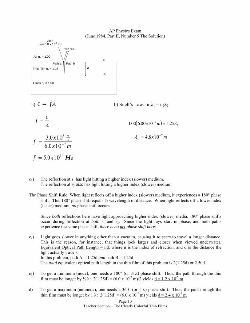
AP Physics Exam (June 1984, Part II, Number 5)
The surface of a glass plate (index of refraction n3 = 1.50) is coated with a transparent thin film (index of refraction n2 = 1.25). A beam of monochromatic light of wavelength 6.00 X 10⁻⁷ meter traveling in air (index of refraction n1 = 1.00) is incident normally on surface s1 as shown below. The beam is partially transmitted and partially reflected. The beam of light in the film is then partially transmitted and partially reflected at surface S2. (a) Calculate the frequency of the light. (b) Calculate the wavelength of the light in the thin film. (c) Calculate the minimum thickness d1 of the film such that the resultant intensity of the light reflected back into the air is a minimum. (d) Calculate the minimum nonzero thickness d2 of the film such that the resultant intensity of the light reflected back into the air is a maximum. Light Air n1 = 1.00 Thin film n2 = 1.25 d
Glass n3 = 1.50
S1
S2
Page 9 Teacher Section – The Clearly Colorful Thin Films
AP Physics Exam
(June 1984, Part II, Number 5 The Solution)
Glass n3 = 1.50
Thin Film n2 = 1.25
Air n1 = 1.00
Light( = 6.0 x 10⁻⁷ m)
Path a Path bd
s1
s2
View here
a) c f= λ b) Snell’s Law: n1λ1 = n2λ2
fc
=λ
( )100 6 00 10 12572. . .x m− = λ
fxx m
ms= −
3 0 106 0 10
8
7
..
λ274 8 10= −. x m
f x Hz= 5 0 1014.
c1) The reflection at s1 has light hitting a higher index (slower) medium. The reflection at s2 also has light hitting a higher index (slower) medium. The Phase Shift Rule: When light reflects off a higher index (slower) medium, it experiences a 180° phase
shift. This 180° phase shift equals ½ wavelength of distance. When light reflects off a lower index (faster) medium, no phase shift occurs.
Since both reflections here have light approaching higher index (slower) media, 180° phase shifts occur during reflection at both s1 and s2. Since the light rays start in phase, and both paths experience the same phase shift, there is no net phase shift here!
c2) Light goes slower in anything other than a vacuum, causing it to seem to travel a longer distance.
This is the reason, for instance, that things look larger and closer when viewed underwater. Equivalent Optical Path Length = nd, where n is the index of refraction, and d is the distance the light actually travels.
In this problem, path A = 1.25d and path B = 1.25d The total equivalent optical path length in the thin film of this problem is 2(1.25d) or 2.50d c3) To get a minimum (node), one needs a 180° (or ½ λ) phase shift. Thus, the path through the thin
film must be longer by ½ λ: 2(1.25d) = (6.0 x 10⁻⁷ m)/2 yields d = 1.2 x 10⁻⁷ m d) To get a maximum (antinode), one needs a 360° (or 1 λ) phase shift. Thus, the path through the
thin film must be longer by 1 λ: 2(1.25d) = (6.0 x 10⁻⁷ m) yields d = 2.4 x 10⁻⁷ m Page 10
Teacher Section – The Clearly Colorful Thin Films
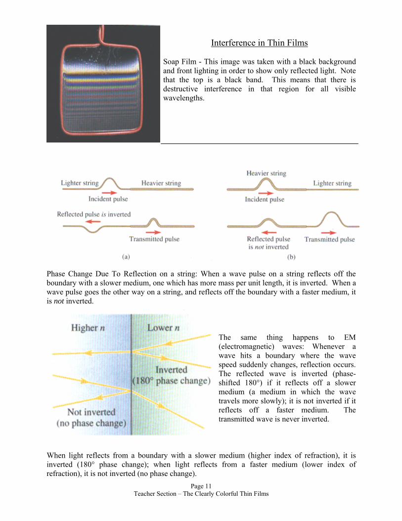
Interference in Thin Films Soap Film - This image was taken with a black background and front lighting in order to show only reflected light. Note that the top is a black band. This means that there is destructive interference in that region for all visible wavelengths.
Phase Change Due To Reflection on a string: When a wave pulse on a string reflects off the boundary with a slower medium, one which has more mass per unit length, it is inverted. When a wave pulse goes the other way on a string, and reflects off the boundary with a faster medium, it is not inverted.
The same thing happens to EM (electromagnetic) waves: Whenever a wave hits a boundary where the wave speed suddenly changes, reflection occurs. The reflected wave is inverted (phase-shifted 180°) if it reflects off a slower medium (a medium in which the wave travels more slowly); it is not inverted if it reflects off a faster medium. The transmitted wave is never inverted.
When light reflects from a boundary with a slower medium (higher index of refraction), it is inverted (180° phase change); when light reflects from a faster medium (lower index of refraction), it is not inverted (no phase change).
Page 11 Teacher Section – The Clearly Colorful Thin Films
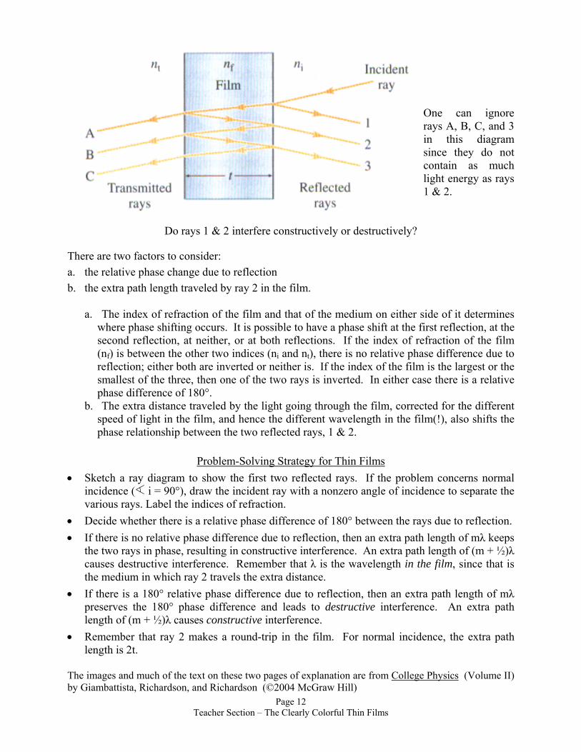
One can ignore rays A, B, C, and 3 in this diagram since they do not contain as much light energy as rays 1 & 2.
Do rays 1 & 2 interfere constructively or destructively? There are two factors to consider: a. the relative phase change due to reflection b. the extra path length traveled by ray 2 in the film.
a. The index of refraction of the film and that of the medium on either side of it determines where phase shifting occurs. It is possible to have a phase shift at the first reflection, at the second reflection, at neither, or at both reflections. If the index of refraction of the film (nf) is between the other two indices (ni and nt), there is no relative phase difference due to reflection; either both are inverted or neither is. If the index of the film is the largest or the smallest of the three, then one of the two rays is inverted. In either case there is a relative phase difference of 180°.
b. The extra distance traveled by the light going through the film, corrected for the different speed of light in the film, and hence the different wavelength in the film(!), also shifts the phase relationship between the two reflected rays, 1 & 2.
Problem-Solving Strategy for Thin Films
• Sketch a ray diagram to show the first two reflected rays. If the problem concerns normal incidence ( i = 90°), draw the incident ray with a nonzero angle of incidence to separate the various rays. Label the indices of refraction.
• Decide whether there is a relative phase difference of 180° between the rays due to reflection. • If there is no relative phase difference due to reflection, then an extra path length of mλ keeps
the two rays in phase, resulting in constructive interference. An extra path length of (m + ½)λ causes destructive interference. Remember that λ is the wavelength in the film, since that is the medium in which ray 2 travels the extra distance.
• If there is a 180° relative phase difference due to reflection, then an extra path length of mλ preserves the 180° phase difference and leads to destructive interference. An extra path length of (m + ½)λ causes constructive interference.
• Remember that ray 2 makes a round-trip in the film. For normal incidence, the extra path length is 2t.
The images and much of the text on these two pages of explanation are from College Physics (Volume II) by Giambattista, Richardson, and Richardson (©2004 McGraw Hill)
Page 12 Teacher Section – The Clearly Colorful Thin Films
Want more on thin films? Try these: Bubbles: http://www.exploratorium.edu/ronh/bubbles/bubbles.html http://www.funsci.com/fun3_en/exper2/exper2.htm http://webexhibits.org/causesofcolor/15.html This is an absolutely WONDERFUL website! Great photos and clear explanations of color in butterflies, mother of pearl, peacock feathers, etc.! http://www.opticsexpress.org/ViewMedia.cfm?id=63420&seq=0. This is a scientific article that discusses different levels of iridescence in different species of butterfly. Angle of view is an important factor. http://www.hero.ac.uk/uk/research/archives/2005/natural_brilliance.cfm Interesting analogy of high light emission by butterfly wing to LED emission of light. http://www.wired.com/news/technology/0,68683-0.html A news article on use of thin films in making iridescent cosmetics http://www.sciencenews.org/pages/sn_arc97/12_13_97/fob3.htm Possible use of info from butterfly wing irridescense in mechanical engineering Pennisi, E. 1993. Chitin craze. Science News 144(July 31):72. Peterson, I. 1997. From microdevice to smart dust. Science News 152(July 26):62. ______. 1995. Butterfly blue. Science News 148(Nov. 4):296.
Page 13 Teacher Section – The Clearly Colorful Thin Films
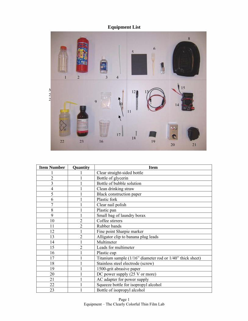
Equipment List
Page 1
Item Number Quantity Item 1 1 Clear straight-sided bottle 2 1 Bottle of glycerin 3 1 Bottle of bubble solution 4 1 Clean drinking straw 5 1 Black construction paper 6 1 Plastic fork 7 1 Clear nail polish 8 1 Plastic pan 9 1 Small bag of laundry borax
10 2 Coffee stirrers 11 2 Rubber bands 12 1 Fine point Sharpie marker 13 2 Alligator clip to banana plug leads 14 1 Multimeter 15 2 Leads for multimeter 16 1 Plastic cup 17 1 Titanium sample (1/16” diameter rod or 1/40” thick sheet) 18 1 Stainless steel electrode (screw) 19 1 1500-grit abrasive paper 20 1 DC power supply (25 V or more) 21 1 AC adapter for power supply 22 1 Squeeze bottle for isopropyl alcohol 23 1 Bottle of isopropyl alcohol
Not pictured: 24: Water 25: Paper towels
8
65
7
1 2 3 4
15 12 13
9 10 1411
1718
22 23 16 1920 21
Equipment – The Clearly Colorful Thin Film Lab
THE CLEARLY COLORFUL THIN FILM LAB
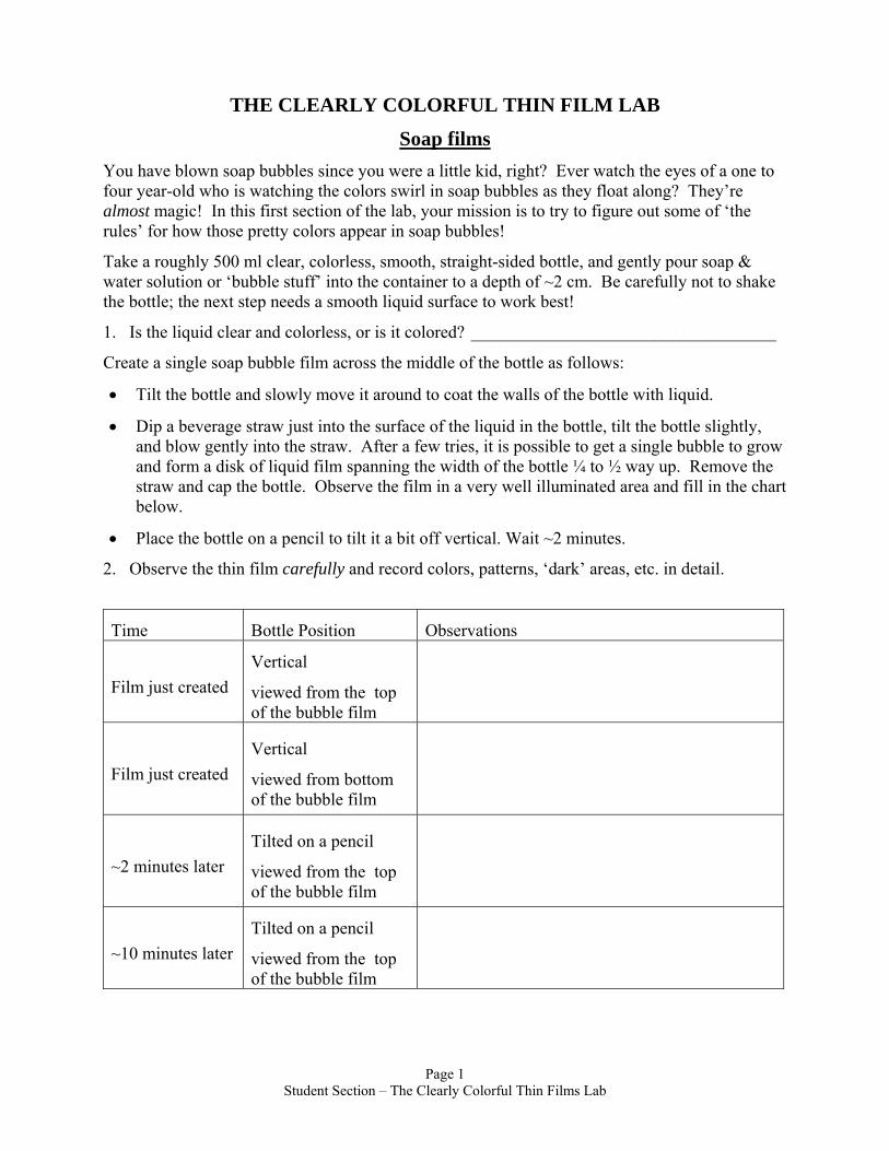
Soap films You have blown soap bubbles since you were a little kid, right? Ever watch the eyes of a one to four year-old who is watching the colors swirl in soap bubbles as they float along? They’re almost magic! In this first section of the lab, your mission is to try to figure out some of ‘the rules’ for how those pretty colors appear in soap bubbles!
Take a roughly 500 ml clear, colorless, smooth, straight-sided bottle, and gently pour soap & water solution or ‘bubble stuff’ into the container to a depth of ~2 cm. Be carefully not to shake the bottle; the next step needs a smooth liquid surface to work best!
1. Is the liquid clear and colorless, or is it colored? ___________________________________
Create a single soap bubble film across the middle of the bottle as follows:
• Tilt the bottle and slowly move it around to coat the walls of the bottle with liquid.
• Dip a beverage straw just into the surface of the liquid in the bottle, tilt the bottle slightly, and blow gently into the straw. After a few tries, it is possible to get a single bubble to grow and form a disk of liquid film spanning the width of the bottle ¼ to ½ way up. Remove the straw and cap the bottle. Observe the film in a very well illuminated area and fill in the chart below.
• Place the bottle on a pencil to tilt it a bit off vertical. Wait ~2 minutes.
2. Observe the thin film carefully and record colors, patterns, ‘dark’ areas, etc. in detail.
Time Bottle Position Observations
Film just created Vertical
viewed from the top of the bubble film
Film just created Vertical
viewed from bottom of the bubble film
~2 minutes later Tilted on a pencil
viewed from the top of the bubble film
~10 minutes later Tilted on a pencil
viewed from the top of the bubble film
Page 1 Student Section – The Clearly Colorful Thin Films Lab
3. The liquid used here is clear and colorless, and yet the film shows beautiful colors when illuminated with white light! Considering what white light is, where might the colors be coming from?
4. If the film was illuminated with monochromatic red light instead of white light,
a. Formerly red areas would look _______________
b. Formerly blue areas would look _______________
5. This film is a liquid, and liquids flow. Use these facts to propose an explanation for the swirling movement of the colors seen in soap bubble films.
6. This film is a liquid, liquid flows, and gravity does effect it. When the bottle is left tilted for a period of time,
a. Where does the film become thickest? _________________________________________
b. Where does the film become thinnest? ________________________________________
c. If 25 dots could be placed at points that all have the same film thickness, what would their placement look like?
________________________________________________________________________
d. What effect does this thickness gradient (transition) appear to have on the color pattern?
________________________________________________________________________
e. Describe any complete visible spectrum (ROYGBIV) patterns observed.
________________________________________________________________________
________________________________________________________________________
7. A clear/colorless or dark/black area will eventually become apparent in the tilted film.
a. Roughly when and where in the film does it appear?
________________________________________________________________________
b. Does such an area seem to grow larger or shrink with time? _______________________
Page 2
Student Section – The Clearly Colorful Thin Films Lab
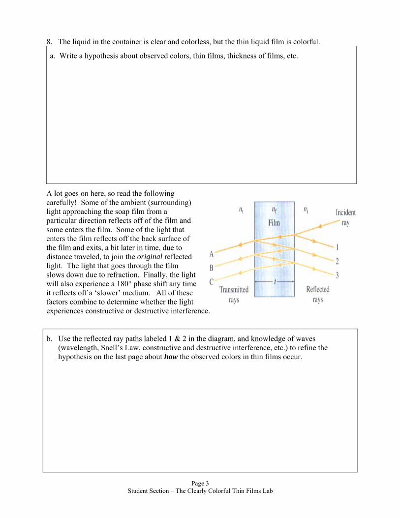
8. The liquid in the container is clear and colorless, but the thin liquid film is colorful.
a. Write a hypothesis about observed colors, thin films, thickness of films, etc.
A lot goes on here, so read the following carefully! Some of the ambient (surrounding) light approaching the soap film from a particular direction reflects off of the film and some enters the film. Some of the light that enters the film reflects off the back surface of the film and exits, a bit later in time, due to distance traveled, to join the original reflected light. The light that goes through the film slows down due to refraction. Finally, the light will also experience a 180° phase shift any time it reflects off a ‘slower’ medium. All of these factors combine to determine whether the light experiences constructive or destructive interference.
b. Use the reflected ray paths labeled 1 & 2 in the diagram, and knowledge of waves (wavelength, Snell’s Law, constructive and destructive interference, etc.) to refine the hypothesis on the last page about how the observed colors in thin films occur.
Page 3 Student Section – The Clearly Colorful Thin Films Lab
Nail Polish Films This section of the lab will create a more permanent thin film and help with development of a hypothesis on colors observed in thin films. Bonus: You get a cool bookmark to take home!
Create a nail polish thin film to observe as follows: • Fill a shallow, open container to a water depth of 2-3 cm • Submerge a piece of black paper and hold it as it absorbs enough water to stay submerged. • Drop ONE drop of clear nail polish onto the water surface from 5-10 cm up. The nail polish
drop should spread out within a couple of seconds, creating an extremely thin film on the surface of the water and revealing a rainbow of colors.
• Carefully and smoothly lift/slide the paper out of the water, capturing the film on the surface of the paper. Place your captured nail polish thin film on a paper towel and allow it to dry completely. Be careful, the film is very fragile until it is dry.
• Use a plastic fork to skim out any remaining film and have each lab partner capture a film. Try different drop techniques to determine which seems to be best. If a film does not spread out well, simply skim it out and try again.
1. What were the dropping techniques tried, in order from best to worst?
a. _______________________ b. _______________________ c. _______________________ d. _______________________
2. From the way this film was created, where is it likely to be thickest? _________________
3. From the way this film was created, where is it likely to be thinnest? _________________
4. Roughly what shape is the pattern of colors in the nail polish thin films? _______________________________________________________________________ Observe the nail polish films from various angles to the plane of the paper. 5. What happens to the position where a particular color is seen as the viewing angle changes? ___________________________________________________________________________ 6. The path of light into and out of the film is shortest when viewing ___________________
a. straight towards the paper. b. at an angle almost parallel to the paper.
Page 4 Student Section – The Clearly Colorful Thin Films Lab
7. How do the observations of nail polish films support the thin film hypothesis developed
with soap bubble films? (If the hypothesis is not fully supported, then it must be modified here to explain nail polish films!)
Page 5 Student Section – The Clearly Colorful Thin Films Lab
Titanium Metal with Titanium Dioxide Thin Films BACKGROUND
Titanium (Ti) is light in both mass and color. It is a strong, corrosion resistant gray metal. It is so light that it is used in some of the best racing bicycle frames and in jet aircraft! It is also used in everything from surgical implants to jewelry to thin films in nanoscale semiconductor electronic devices and special thin film coatings.
In the nanofabrication of electronic integrated circuits, (computer chips and the like), thin films of material are either deposited on a surface or etched away from a surface, in a very specific pattern. The pattern is obtained by using a mask, a stenciled on pattern which protects the region one wants left unaffected. You will see how a mask is used as part of this lab!
The electrochemical process in this lab, called anodizing, uses a redox reaction to form a thin film of TiO2 on a sample of metallic titanium.
1. TiO2 is a clear and colorless material. Predict what will happen when a thin film of TiO2 is deposited on Ti metal.
______________________________________________________________________________
______________________________________________________________________________
Creating a TiO2 thin film on Ti:
PREP WORK • File any sharp edges off the Ti sample. Use fine emery paper or extremely fine wet/dry
abrasive paper to polish the Ti as smooth as possible. Start with the smaller number abrasives, and move to the higher numbers. Wetting the abrasive with water that contains a drop of dish soap or a dab of toothpaste can help in the polishing process. The brighter the finish now, the better the results later!
• Clean oils, grease, and sanding residue from the Ti with a few drops of isopropyl alcohol on paper towel. After cleaning, handle the Ti by its edges and as little as possible.
• Create a mask on the Ti by dabbing waterproof ink fairly thickly onto the metal in the regions to remain Ti grey colored. Fairly thin lines are ok, but must coat the metal well. Draw rings around the Ti wire at 1 cm intervals down its length for reference later in the experiment. If Ti strips are used, draw lines at 1 cm intervals on one side, and whatever pattern you like on the other. Allow time for the ink to dry well!
• Fill a cup with enough water to almost completely submerge a vertical Ti sample. • Dissolve 1 slightly rounded teaspoon of sodium tetraborate in the water. The exact amounts
are not critical, and run about 7 grams in about 200 ml of water.
2. As stated, this lab uses an electrochemical reaction. The sodium tetraborate (laundry borax) solution in the reaction cup is the electrolyte. The mobile positive and negative ions in the solution make it a good electrical _________________________.
Page 6 Student Section – The Clearly Colorful Thin Films Lab
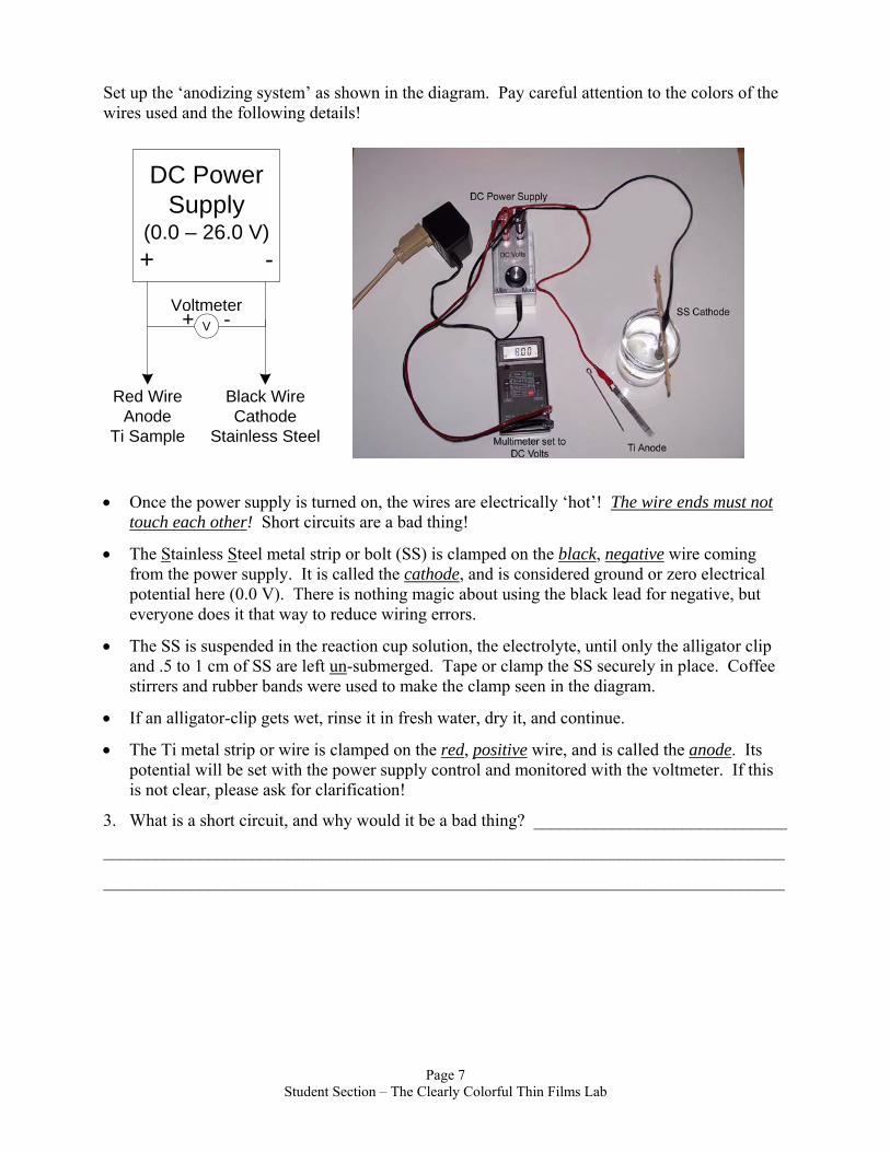
Set up the ‘anodizing system’ as shown in the diagram. Pay careful attention to the colors of the wires used and the following details!
DC PowerSupply
(0.0 – 26.0 V)+ -
V
Red WireAnode
Ti Sample
Black WireCathode
Stainless Steel
+ -Voltmeter
• Once the power supply is turned on, the wires are electrically ‘hot’! The wire ends must not touch each other! Short circuits are a bad thing!
• The Stainless Steel metal strip or bolt (SS) is clamped on the black, negative wire coming from the power supply. It is called the cathode, and is considered ground or zero electrical potential here (0.0 V). There is nothing magic about using the black lead for negative, but everyone does it that way to reduce wiring errors.
• The SS is suspended in the reaction cup solution, the electrolyte, until only the alligator clip and .5 to 1 cm of SS are left un-submerged. Tape or clamp the SS securely in place. Coffee stirrers and rubber bands were used to make the clamp seen in the diagram.
• If an alligator-clip gets wet, rinse it in fresh water, dry it, and continue.
• The Ti metal strip or wire is clamped on the red, positive wire, and is called the anode. Its potential will be set with the power supply control and monitored with the voltmeter. If this is not clear, please ask for clarification!
3. What is a short circuit, and why would it be a bad thing? _____________________________
______________________________________________________________________________
______________________________________________________________________________
Page 7 Student Section – The Clearly Colorful Thin Films Lab

ANODIZING
**Be Careful! Do not touch the SS with the Ti!
Keep the alligator clips out of the electrolyte!
The anodizing procedure is repeated using the voltages, and immersion depths in the order listed in the data table. Study the table, especially the immersion depths, and proceed as follows: • Set the power supply to the first voltage specified in the table. The steps MUST be done in
order! • Lower the Ti vertically into the reaction cup to the depth of immersion shown in the table,
hold it steady for 30. seconds, and then remove it. Dab the Ti dry above the next immersion line with a paper towel. Record observations in the chart.
• Repeat this process, adjusting the voltage to the new value in the table, and decreasing the amount of Ti immersion by 1.0 cm each time.
• Do not touch the metal. The ink mask is not durable! If some of the ink appears to have come off, dry the metal and apply fresh ink before continuing.
• In the event of problems, sand the Ti clean and start over. The TiO2 film is quite durable, but it will sand off with some effort.
• Use a few drops of isopropyl alcohol on a scrap of paper towel to clean the ink off the Ti.
4. The ink wipes off the Ti easily, but does the color wipe off easily? _____________________ • When done anodizing, pour the sodium tetraborate solution from your reaction cup into the
class storage container and clean up your work area. OPTIONAL READING about the chemistry of the process just completed: [In chemistry class, you electrolyzed water using two relatively inert electrodes. You observed that hydrogen bubbled off at the negative electrode (the cathode), and oxygen bubbled off at the positive electrode (the anode). The actual chemical reaction was: 2H2O 2H2 + O2. If the electrodes are made of reactive materials, they will react! If the anode is made of copper, it will react with the oxygen and make a dark copper oxide film coating the copper. The copper will ‘tarnish’. Even though a fairly large number of hydrogen bubbles appeared at the cathode in today’s experiment, there were hardly any bubbles of O2 observed on the Ti anode in this experiment. Where did the oxygen go? In fact, it reacted with the titanium according to the equation: Ti + O2 TiO2 (This is actually a redox reaction, which is the combination of the two half-cell reactions: Ti Ti+4 + 4e- and O2 + 4e- 2O-2 Note that the charges balance!). Thus, the anodizing process resulted in a thin film of TiO2 on the surface of the Ti metal.]
No tints or dyes were used here, and yet lovely colors did appear! 5. A copper oxide coating on copper is a dark tarnish. An iron oxide coating on iron is rust, and
we all know what that looks like! A titanium dioxide coating on titanium can’t be all the different colors seen on the lab sample. What color is TiO2? __________________________
6. While titanium metal conducts electricity very well, TiO2 does not! When current flows, the
TiO2 film grows thicker quite quickly, at first. The thickening film causes the total electrical Page 8
Student Section – The Clearly Colorful Thin Films Lab
resistance to (increase, decrease, remain the same), which causes the electrical current to (increase, decrease, remain the same), which causes the chemical reaction rate to (increase, decrease, remain the same). There is almost no current left at the end of each 30. second run. The voltage is increased for each successive process in order to overcome the above changes!
7. Which segment of the titanium sample has the thinnest TiO2 film coating? _______________ 8. Increasing thicknesses of TiO2 film produced different colors. Explain how this is consistent
with the hypothesis developed using soap and nail polish films.
9. Postulate an explanation of how anti-counterfeiting color shifting ink (Observe it from a different angle and it looks like a different color) on modern paper money might work.
10. Postulate an explanation of how the bright iridescent colors seen in butterfly wings might be formed with scales of clear, colorless chitin.
Integrated circuits (ICs) are the small rectangular grey electronic components with many wires seen all over the circuit boards of computers, cell phones, televisions, etc. They contain the equivalent of hundreds, thousands, or even millions of simpler electronic components inside. They are created by layering complex nanoscale patterns of thin films of ‘n’ (negative) and ‘p’ (positive) materials on a silicon base. In making the patterns, a mask is lithographically applied to the surface. It is a bit like silk- screen printing on T-shirts reduced to nanoscale. Then material is either etched away from the areas that are unprotected by the mask or deposited onto
Page 9 Student Section – The Clearly Colorful Thin Films Lab

the material in those areas. The mask is then removed and the next layer’s pattern mask is applied.
11. How is the titanium thin film part of this lab similar to the IC manufacturing process?
12. How is the titanium thin film part of this lab different from the IC manufacturing process?
13. The colors on the titanium in this experiment appeared in a specific order. Jewelry artists working with this medium get the colors they want in the locations they want them. How do they do it, and how might a different order of colors be obtained in this lab experiment?
14. If time and materials permit, try to create a titanium wire with colors in the order:
Blue, gold, purple, gold, blue
Page 10 Student Section – The Clearly Colorful Thin Films Lab
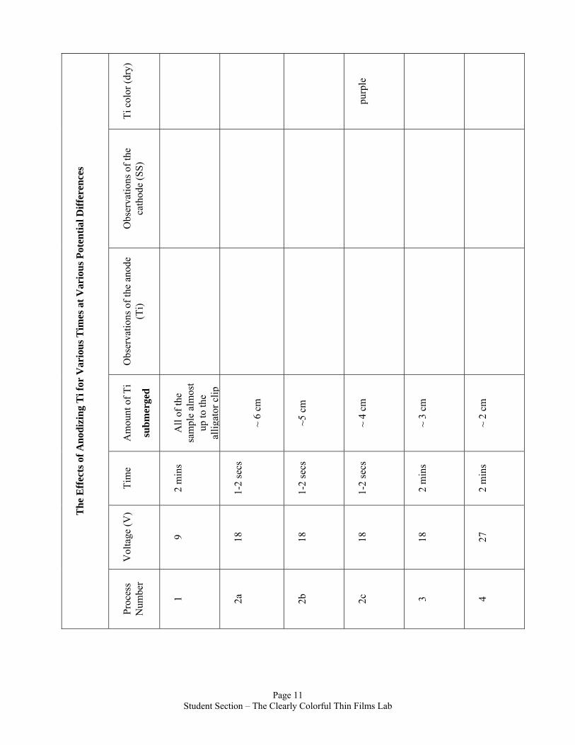
Ti c
olor
(dry
)
purp
le
Obs
erva
tions
of t
he
cath
ode
(SS)
Obs
erva
tions
of t
he a
node
(T
i)
Am
ount
of T
i
subm
erge
d
All
of th
e sa
mpl
e al
mos
t up
to th
e al
li gat
or c
lip
~ 6
cm
~5 c
m
~ 4
cm
~ 3
cm
~ 2
cm
Tim
e
2 m
ins
1-2
secs
1-2
secs
1-2
secs
2 m
ins
2 m
ins
Vol
tage
(V)
9 18
18
18
18
27
The
Eff
ects
of A
nodi
zing
Ti f
or V
ario
us T
imes
at V
ario
us P
oten
tial D
iffer
ence
s
Proc
ess
Num
ber
1 2a
2b
2c
3 4
Page 11
Student Section – The Clearly Colorful Thin Films Lab
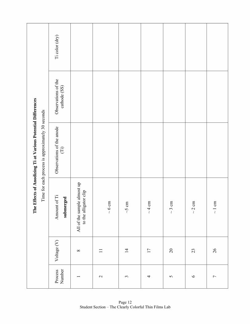
Ti c
olor
(dry
)
Obs
erva
tions
of t
he
cath
ode
(SS)
Obs
erva
tions
of t
he a
node
(T
i)
Am
ount
of T
i
subm
erge
d
All
of th
e sa
mpl
e al
mos
t up
to th
e al
ligat
or c
lip
~ 6
cm
~5 c
m
~ 4
cm
~ 3
cm
~ 2
cm
~ 1
cm
Vol
tage
(V)
8 11
14
17
20
23
26
The
Eff
ects
of A
nodi
zing
Ti a
t Var
ious
Pot
entia
l Diff
eren
ces
Tim
e fo
r eac
h pr
oces
s is a
ppro
xim
atel
y 30
seco
nds
Proc
ess
Num
ber
1 2 3 4 5 6 7
Page 12
Student Section – The Clearly Colorful Thin Films Lab