clean room rodless cylinder series cyp · clean room rodless cylinder series cyp ø15, ø32...
TRANSCRIPT

Clean Room Rodless Cylinder
Series CYPø15, ø32
CAT.ES20-148 A
Magnetically coupled rodless cylinder for transfer in clean environments

Model
Piping port position
Operating direction
Nil
a
Right
b
Left
L
c
Right
d
Left
R
e
Right
f
Left
S
g
Right
h
Left
Note 1) This chart indicates the level of cleanliness inside the measurement chamber.
Note 2) The vertical axis shows the number of particles per unit volume (1m³) of air which are no smaller than the particle size shown on the horizontal axis.
Note 3) The gray lines show the upper concentration limit of the cleanliness class based on Fed.Std.209E-1992.
Note 4) The plots indicate the 95% upper reliability limit value for time series data up to 500 thousand operation cycles. (Cylinder: CYP32-200, Work piece weight: 5kg, Average speed: 2000mm/s)
Note 5) The data above provide a guide for selection but is not guaranteed.
Low particle generation: 1/20 High cleanliness is achieved with non-contact
construction of the cylinder tube exterior and a stainless steel linear guide (specially treated).
Particle generation has been reduced to 1/20 com-pared to series 12-CY1B (previous SMC product) even without vacuum suction.
Particle diameter (µm) Par
ticle
con
cent
ratio
n (p
artic
les/
m³)
10⁰
0.01 0.1 1 10
10¹
10²
10³
10⁴
10⁵
Class M3.5 [Class100]
Class M2.5 [Class10]
Class M1.5[Class1]
Note) Plugs are installed in ports other than those indicated for the model.
Nil L R Sa b h gdc feOperating direction
←Left Right→
Piping port variations provide a high degree of freedomPiping port positions can be selected to accommodate the installation.
There is no particulate generation from sliding, because the construction avoids contact between the cylinder tube's exterior surface and the slide table's interior surface.
Non-contact construction
The specially treated linear guide achieves low particulate generation, high linearity and high precision.
Stainless steel linear guide(specially treated)
No contact
Cylinder tube
Slide table
Long strokes(Max. 700mm)
(compared to previous series)
Cleaned, assembled and double packaged in a clean room
Features 1

Variations
6 10 15 20 25 32 40 50 63Bore size (mm)
12-CY1B Basic type
Basic typeDirect mount type
Clean room rodless
CYPHigh
precision guide
12-CY1R
Series Guide type
Stroke adjustmentThe stroke adjustment screw allows fine control of the stroke (±1mm on each side)
Shock-freeA sine cushion is used at the end of the stroke.Smooth acceleration and deceleration are possible at 0.5G or less.
Sine cushion
Stroke adjustment screw
A special cylinder tube is employed using extruded aluminum material. Even long strokes are not subject to deflection because of direct attachment to the cylinder body, and non-contact construction is achieved through combination with a linear guide.
Special cylinder tube
SeriesCYP
Series12-
Standard productsCle
an e
nvi
ron
men
t lev
el
Load weightLightLow
High
Heavy
A magnetically coupled rodless cylinder that can be used for
transfer in clean environments
Features 2

How to Order
—
—
5V
12V
5V, 12V
— —
—
—
Y69A
Y7PV
Y69B
Y7NWV
Y7PWV
Y7BWV
Z76
Z73
Z80
Y59A
Y7P
Y59B
Y7NW
Y7PW
Y7BW —
—
—
—
100V
100V or less
5V, 12V
5V , 12V
12V
12V
—
24V
24V
ACDC 0.5(Nil)
3(L)
P.8
P.9
P.10
—
5(Z)
CYP 15 Z73
Clean room rodless cylinder
1532
15mm32mm
Number of auto switchesNilSn
Type of auto switch
Standard stroke
Cylinder bore size
200
Nil
L
R
S
Piping port positionabcdefgh
Select auto switches from the table below.
15, 32 100, 150, 200, 250, 300, 350400, 450, 500, 600, 700
Note 1) Consult SMC if the maximum stroke is exceeded.Note 2) Intermediate strokes are available as a special order.
Piping port position
L R Sa b h gdc fe
Bore size (mm) Standard stroke (mm)
2 pcs.1 pc.
"n" pcs.
Operating direction: RightOperating direction: LeftOperating direction: RightOperating direction: LeftOperating direction: RightOperating direction: LeftOperating direction: RightOperating direction: Left
Note) Plugs are installed in ports other than those indicated for the model.
NilOperating direction
←Left Right→
Reed switch
Solid stateswitch
Type Specialfunction
Electricalentry
Indicatorlight
Wiring(output)
Load voltage
Perpendicular In-line
Auto switch modelsElectrical entry direction
Lead wire length (mm)∗
Applicable loadsDetailedspecifi-cations
IC circuit
—
IC circuit
IC circuit
IC circuit
—
IC circuit
Relay,PLC
Relay,PLC
3 wire
2 wire
3 wire (NPN)
3 wire (PNP)
2 wire
3 wire (NPN)
3 wire (PNP)
2 wire
Yes
No
Yes
Grommet
GrommetDiagnosticindication
(2 color indicator)
∗ Lead wire length symbols: 0.5m ...... Nil (Example) Y69B 3m ......... L Y69BL 5m ......... Z Y69BZ∗∗ Auto switches marked with a "" symbol are produced upon receipt of order.
Applicable auto switches
Nil Without auto switch
Clean Room RodlessCylinder Series CYP
1
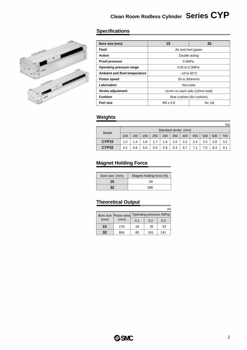
Specifications
Magnet Holding Force
Bore size (mm)
Fluid
Action
Proof pressure
Operating pressure range
Ambient and fluid temperature
Piston speed
Lubrication
Stroke adjustment
Cushion
Port size
Air and inert gases
Double acting
0.5MPa
0.05 to 0.3MPa
–10 to 60°C
50 to 300mm/s
Non-lube
±1mm on each side (±2mm total)
Sine cushion (Air cushion)
M5 x 0.8 Rc 1/8
15 32
Bore size (mm)
15
32
Magnet holding force (N)
59
268
Theoretical Output
15
32
Bore size(mm)
176
804
0.1
18
80
0.2
35
161
0.3
53
241
Piston area(mm)
Operating pressure (MPa)
(N)
(kg)
Weights
Model
CYP15
CYP32
Standard stroke (mm)
100
1.2
4.2
150
1.4
4.6
200
1.6
5.0
250
1.7
5.5
300
1.9
5.9
350
2.0
6.3
400
2.2
6.7
450
2.4
7.1
500
2.5
7.5
600
2.8
8.3
700
3.2
9.1
2
Clean Room Rodless Cylinder Series CYP
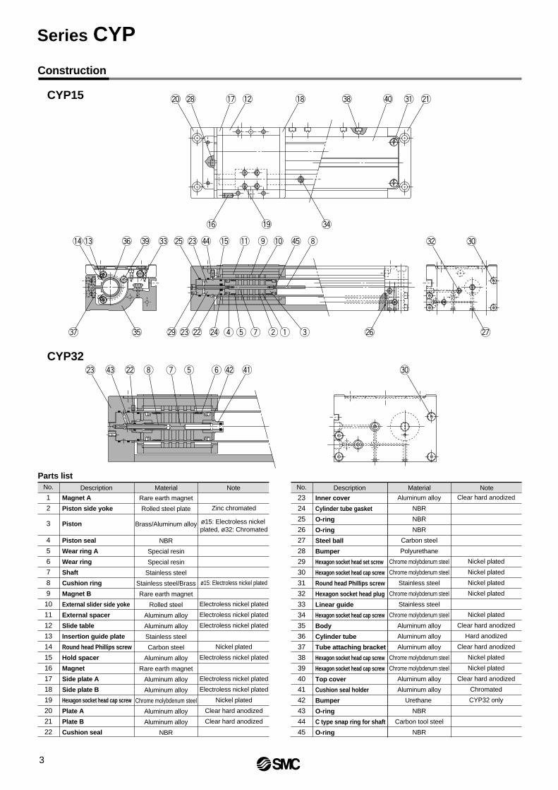
Construction
No.
1
2
3
4
5
6
7
8
9
10
11
12
13
14
15
16
17
18
19
20
21
22
Description Material Note
Parts list
Magnet A
Piston side yoke
Piston
Piston seal
Wear ring A
Wear ring
Shaft
Cushion ring
Magnet B
External slider side yoke
External spacer
Slide table
Insertion guide plate
Round head Phillips screw
Hold spacer
Magnet
Side plate A
Side plate B
Hexagon socket head cap screw
Plate A
Plate B
Cushion seal
Rare earth magnet
Rolled steel plate
Brass/Aluminum alloy
NBR
Special resin
Special resin
Stainless steel
Stainless steel/Brass
Rare earth magnet
Rolled steel
Aluminum alloy
Aluminum alloy
Stainless steel
Carbon steel
Aluminum alloy
Rare earth magnet
Aluminum alloy
Aluminum alloy
Chrome molybdenum steel
Aluminum alloy
Aluminum alloy
NBR
Zinc chromated
ø15: Electroless nickel plated, ø32: Chromated
ø15: Electroless nickel plated
Electroless nickel plated
Electroless nickel plated
Electroless nickel plated
Nickel plated
Electroless nickel plated
Electroless nickel plated
Electroless nickel plated
Nickel plated
Clear hard anodized
Clear hard anodized
No.
23
24
25
26
27
28
29
30
31
32
33
34
35
36
37
38
39
40
41
42
43
44
45
Description Material Note
Inner cover
Cylinder tube gasket
O-ring
O-ring
Steel ball
Bumper
Hexagon socket head set screw
Hexagon socket head cap screw
Round head Phillips screw
Hexagon socket head plug
Linear guide
Hexagon socket head cap screw
Body
Cylinder tube
Tube attaching bracket
Hexagon socket head cap screw
Hexagon socket head cap screw
Top cover
Cushion seal holder
Bumper
O-ring
C type snap ring for shaft
O-ring
Aluminum alloy
NBR
NBR
NBR
Carbon steel
Polyurethane
Chrome molybdenum steel
Chrome molybdenum steel
Stainless steel
Chrome molybdenum steel
Stainless steel
Chrome molybdenum steel
Aluminum alloy
Aluminum alloy
Aluminum alloy
Chrome molybdenum steel
Chrome molybdenum steel
Aluminum alloy
Aluminum alloy
Urethane
NBR
Carbon tool steel
NBR
Clear hard anodized
Nickel plated
Nickel plated
Nickel plated
Nickel plated
Nickel plated
Clear hard anodized
Hard anodized
Clear hard anodized
Nickel plated
Nickel plated
Clear hard anodized
Chromated
CYP32 only
CYP15
CYP32
3
Series CYP

Dimensions
Note 1) These dimension drawings indicate the case of piping port position "Nil".Note 2) These dimensions indicate the protruding portion of the bumper.Note 3) Refer to "Specific Product Precautions [Cushion Effect (Sine Cushion) and Stroke Adjustment] on page 22.
CYP15CYP32
A 812
B 9.514
E4H96H9
ED 9.5
13
EK46
F12.525
G6.58.5
H4575
HA19.539
HB 8.519
HG 8.519
HI2339
HL38.664.9
HP4473.5
HS2749.5
HT19.539
JM6 x 1
M10 x 1.5
JK1012
K2120
L6790
Model
CYP15CYP32
PM5 x 0.8Rc 1/8
PA2550
PB 60100
Q105138
QW4887
R 4579.5
T2329
TA1317
TB1822
W 69115
WA3246
WB1727
Y2.53.5
Z118155
Model
+0.030 0+0.030 0
C5.48.6
LD5.68.6
LW 69115
MMM4 x 0.7M6 x 1
M68
N4.57.5
(mm)
RW
WBWA
HGH
T HS
P (port a)
P (port b)Auto switchmounting groove
HIH
PH
A ALW
TA
TB
HBH
A
HBH
A
TA
TB
4-JDepth JK
Plug
[P (port c)]
Plug
[P (port e)]
Plug
[P (port d)]
Plug
[P (port g)]
Plug
[P (port h)]
Plug
[P (port f)]
0.5 Note 2) 0.5 Note 2)Left Right
Operating direction
HL
HGH
TWB
WAR
HI
F
PA
E depth EKQ + Stroke
Z + Stroke
QW
G
øE
4-MMThread depth M
4-Counter bore dia øBCounter bore depth C
K
PB
N
4-øLD
L
Depth ED
T
A
T Y
Stroke adjustment screw Note 3)
(inner cover)
Inner cover Note 3)
holding screw
4
Clean Room Rodless Cylinder Series CYP
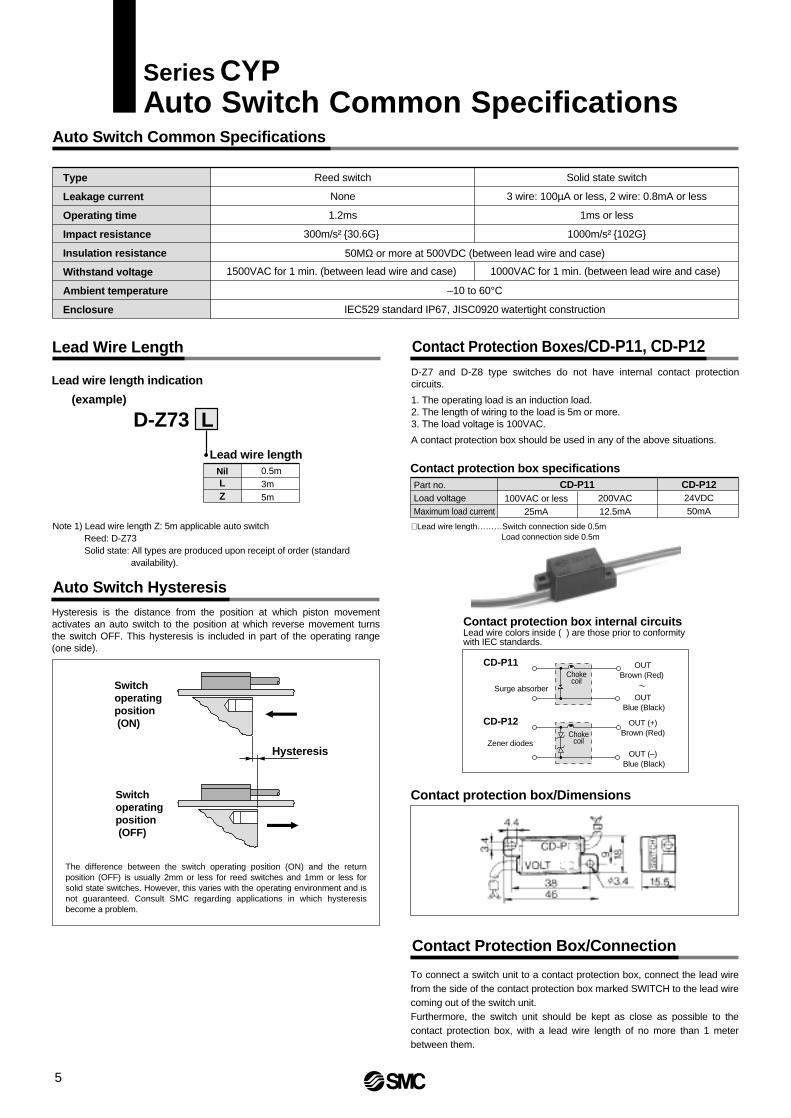
Contact protection box/Dimensions
Auto Switch Common Specifications
Lead Wire Length
Lead wire length indication
(example)
50MΩ or more at 500VDC (between lead wire and case)
–10 to 60°C
IEC529 standard IP67, JISC0920 watertight construction
1500VAC for 1 min. (between lead wire and case) 1000VAC for 1 min. (between lead wire and case)
0.5m3m 5m
LZ
Nil
Lead wire length
LD-Z73
Contact protection box internal circuits
Part no.Load voltageMaximum load current
∗ Lead wire length………Switch connection side 0.5mLoad connection side 0.5m
D-Z7 and D-Z8 type switches do not have internal contact protection circuits.
1. The operating load is an induction load.2. The length of wiring to the load is 5m or more.3. The load voltage is 100VAC.
A contact protection box should be used in any of the above situations.
Surge absorber
Chokecoil
OUTBrown (Red)
OUT Blue (Black)
OUT (+) Brown (Red)
OUT (–) Blue (Black)
ChokecoilZener diodes
CD-P11
CD-P12
Contact Protection Boxes/CD-P11, CD-P12
CD-P11 CD-P1224VDC50mA
200VAC12.5mA
100VAC or less25mA
Contact protection box specifications
To connect a switch unit to a contact protection box, connect the lead wire from the side of the contact protection box marked SWITCH to the lead wire coming out of the switch unit. Furthermore, the switch unit should be kept as close as possible to the contact protection box, with a lead wire length of no more than 1 meter between them.
Contact Protection Box/Connection
Hysteresis is the distance from the position at which piston movement activates an auto switch to the position at which reverse movement turns the switch OFF. This hysteresis is included in part of the operating range (one side).
Lead wire colors inside ( ) are those prior to conformity with IEC standards.
Auto Switch Hysteresis
The difference between the switch operating position (ON) and the return position (OFF) is usually 2mm or less for reed switches and 1mm or less for solid state switches. However, this varies with the operating environment and is not guaranteed. Consult SMC regarding applications in which hysteresis become a problem.
Switchoperatingposition (ON)
Switchoperatingposition (OFF)
Hysteresis
Type
Leakage current
Operating time
Impact resistance
Insulation resistance
Withstand voltage
Ambient temperature
Enclosure
Reed switch
None
1.2ms
300m/s² 30.6G
Solid state switch
3 wire: 100µA or less, 2 wire: 0.8mA or less
1ms or less
1000m/s² 102G
Note 1) Lead wire length Z: 5m applicable auto switchReed: D-Z73Solid state: All types are produced upon receipt of order (standard
availability).
5
Series CYPAuto Switch Common Specifications

Basic Wiring
Solid state 3 wire, NPN
Sink input specifications
2 wire
Source input specifications
2 wire with 2 switch AND connection 2 wire with 2 switch OR connection
2 wire 2 wire
Solid state 3 wire, PNP
Example: Power supply is 24VDC Voltage decline in switch is 4V
Example: Load impedance is 3kΩLeakage current from switch is 1mA
(Power supplies for switch and load are separate.)
Connection Examples for AND (Series) and OR (Parallel)
Examples of Connection to PLC
Connect according to the applicable PLC input specifications, as the connection method will vary de-pending on the PLC input specifica-tions.
When two switches are connected in series, a load may malfunction because the load voltage will de-cline when in the ON state.The indicator lights will light up if both of the switches are in the ON state.
<Solid state>When two switches are connected in parallel, malfunction may occur because the load voltage will increase when in the OFF state.
Blue[Black]
Mainswitchcircuit
Load
Brown [Red]
Black[White]
Mainswitchcircuit
Brown[Red]
Load
Blue[Black]
Black[White]
Mainswitchcircuit
LoadBlue[Black]
Brown[Red]
Mainswitchcircuit
Load
Blue[Black]
Brown[Red]
Mainswitchcircuit
Load
Brown[Red]
Blue[Black]
Black[White]
PLC internal circuitCOM
Switch
InputBlack[White]
Brown[Red]
Blue[Black]
PLC internal circuitCOM
Switch
InputBrown[Red]
Blue[Black] PLC internal circuit
Switch
Input
COM
Blue[Black]
Brown[Red]
PLC internal circuitCOM
Switch
InputBlack[White]
Brown[Red]
Blue[Black]
Switch 1
Switch 2
Load
Blue[Black]
Brown[Red]
Blue[Black]
Brown[Red]
Switch 1
Switch 2
Load
Brown[Red]
Blue[Black]
Brown[Red]
Blue[Black]
3 wireOR connection for NPN output
Switch 1
Switch 2
LoadSwitch 1
Brown[Red]
Switch 2
Black[White]
Blue[Black]
Relay
RelayBlack[White]
Load
Relaycontact
AND connection for NPN output(using relays)
Switch 1
Brown[Red]
Switch 2
Load
Brown[Red]
AND connection for NPN output(performed with switches only)
The indicator lights will light up when both switches are turned ON.
<Reed switch>
2 wire
Indicatorlight,
protectioncircuit,
etc.
Brown[Red]
Blue[Black]
Load
<Reed switch>
Brown[Red]
Blue[Black]
Load
<Solid state>
3 wire, NPN 3 wire, PNP
Brown [Red]
Blue[Black]
Blue[Black]
Black[White]
Black[White]
Blue[Black]
Brown[Red]
Blue[Black]
Black[White]
Blue[Black]
Black[White]
Brown[Red]
Because there is no current leakage, the load voltage will not increase when turned OFF. However, depending on the number of switches in the ON state, the indicator lights may sometimes get dark or not light up, because of dispersion and reduction of the current flowing to the switches.
Indicatorlight,
protectioncircuit,
etc.
Load voltage at ON = – x 2 pcs.
= 24V – 4V x 2 pcs. = 16V
Power supply voltage
Residual voltage
Leakagecurrent
LoadimpedanceLoad voltage at OFF = x 2 pcs. x
= 1mA x 2 pcs. x 3kΩ= 6V
6
Series CYPAuto Switch Connections and Examples

Auto Switch Mounting
24.5
33
CYP15
CYP32
Auto switchmodel
Cylinder model
Auto Switch Operating Range
A
A
B
D-Y5D-Y6D-Y7PD-Y7PV
93.5
122
Proper auto switch mounting position
6.5
9.5
2.5
3
Auto switchmodel
Cylinder model
D-Z7D-Z80
D-Y7WD-Y7WVD-Y5D-Y6D-Y7PD-Y7PV
Auto Switches/Proper Mounting Position for Stroke End Detection
D-Z7D-Z80
D-Y7WD-Y7WV
D-Y5D-Y6D-Y7PD-Y7PV
D-Y7WD-Y7WV
D-Z7D-Z80
CYP15
CYP32
SM
C
SM
C
Auto switch
Watchmakers screw driver
Set screw (included with auto switch)
B
Note) Operating ranges are standards including hysteresis, and are not guaranteed. (variations on the order of ±30%)Large variations may occur depending on the surrounding environment.
When mounting auto switches, they should be
inserted into the cylinder's switch groove
from the direction shown in the drawing
on the right. After setting in the
mounting position, use a flat head
watchmakers screw driver to
tighten the set screw which is
included.
Note) When tightening the auto switch set screw (included with the auto switch), use a watchmakers screw driver with a handle about 5 to 6mm in diameter. The tightening torque should be approximately 0.05 to 0.1N⋅m.
7
Series CYPAuto Switch Mounting

D-Z76
Auto Switch Specifications
With indicator light
Auto switch part no.
Electrical entry direction
Applicable load
Load voltage
Maximum load current
Contact protection circuit
Internal resistance
In-line
Relay, PLC, IC circuit
48V
40mA
None
1Ω or less (including lead wire length of 3m)
Auto switch part no.
Electrical entry direction
Applicable loads
Load voltage
Contact protection circuit
Internal voltage drop
Indicator light
Maximum load currentor current range
D-Z73 D-Z76
Relay, PLC
2.4V or less (to 20mA)/3V or less (to 40mA)
IC circuit
4 to 8VDC
20mA
0.8V or less
24VDC
5 to 40mA
Weights
D-Z73
D-Z76
D-Z80
Lead wire length 0.5m Lead wire length 3m
Unit: g
Internal circuits
D-Z73
D-Z80
In-line
100VAC
5 to 20mA
None
Red LED lights up when ON
24V or less
50mA
ACDC 100V
20mA
(+)
(–)
Without indicator lightD-Z80
Dimensions
Model
7
10
9
31
55
49
D-Z73
D-Z76, Z80
Ree
d sw
itch Resistor
Zener diode
Contactprotectionbox
CD-P11
CD-P12
Brown [Red]
Blue [Black]
OUT (+)Brown [Red]
OUT (–)Blue [Black]
LED
Ree
d sw
itch Resistor
Reversecurrentpreventiondiode
OUTBlack [White]
DC (+)Brown [Red]
DC (–)Blue [Black]
Load DC powersupply
Ree
d sw
itch Contact
protectionbox
CD-P11
CD-P12
OUT (±)Brown [Red]
OUT ( )Blue [Black]
±
LED
ACDC
ACDC
Note) 1. The load is an induction load.2. The lead wire length to the load is 5m or more.3. The load voltage is 100VAC.
Use a contact protection box in any of the above situations, as the life of the contacts may otherwise be reduced. (Refer to page 5 for detailed specifications of the contact protection boxes.)
Lead wires —— Oil resistant vinyl heavy duty cord, ø3.4,0.2mm², 2 wire [Brown, Blue (Red, Black)], 3 wire [Brown, Black, Blue (Red, White, Black)],0.5m (D-Z73 only ø2.7, 0.18mm², 2 wire)
Note) Refer to page 5 for auto switch common specifications and lead wire lengths.
6.2
30.5
Indicator light
2.3
5.5
12.5 Most sensitive position
ø2.
7
Switch mounting screw
Slotted set screw(M2.5 x 4l)
27.6
6.2
1.5
2.5
5.7
12.5 Most sensitive position
ø3.
4
Switch mounting screw
Slotted set screw(M2.5 x 4l)
Indicator light
Type D-Z80 without indicator light
Reed Switches/Direct Mount TypeD-Z73/Z76/Z80
8

Unit: g
D-Y59A, Y69A, Y7P
D-Y59B, Y69B, Y7PV
Lead wire length
Internal circuits
D-Y59A, Y69A
D-Y59B, Y69B
D-Y7P (V)
D-Y59A, Y59BD-Y7P
D-Y69A, Y69BD-Y7PV
0.5m
10
9
3m
53
50
Model
Dimensions
Auto Switch Specifications
D-Y5, D-Y6, D-Y7P, D-Y7PV (with indicator light)Auto switch part no.
Electrical entry direction
Wiring type
Output type
Applicable loads
Power supply voltage
Current consumption
Load voltage
Load current
Internal voltage drop
Leakage current
Indicator light
D-Y59A
In-line
D-Y69A
Perpendicular
D-Y59B
In-line
D-Y69B
Perpendicular
2 wire
–
24VDC Relay, PLC
–
–
24VDC (10 to 28VDC)
5 to 40mA
4V or less
0.8mA or less at 24VDC
3 wire
IC circuit, Relay, PLC
5, 12, 24VDC (4.5 to 28VDC)
100µA or less at 24VDC
Red LED lights up when ON
D-Y7P
In-line
D-Y7PV
Perpendicular
NPN PNP
28VDC or less
40mA or less
–
80mA or less
0.8V or less
10mA or less
1.5V or less(0.8V or less at 10mA load current)
OUTBlack [White]
DC (+)Brown [Red]
DC (–)Blue [Black]
Mai
n sw
itch
circ
uit
DC (+)Brown [Red]
DC (–)Blue [Black]
OUTBlack [White]M
ain
switc
hci
rcui
tM
ain
switc
hci
rcui
t
OUT (+)Brown [Red]
OUT (–)Blue [Black]
Lead wires—Oil resistant, flexible vinyl heavy duty cord, ø3.4, 0.15mm², 3 wire [Brown, Black, Blue (Red, White, Black)], 2 wire [Brown, Blue (Red, Black)], 0.5m
Note) Refer to page 5 for auto switch common specifications and lead wire lengths.
Weights
Indicator light2.5
6.2
5
29 (500) (3000) (5000)
ø3.
4
12.5 Most sensitive positon
Mounting screw M2.5 x 4l
Slotted set screw
Indicator light
6.2
(50
0) (
3000
) (5
000)
5 8.5
12.5 Most sensitive positon
2.5
27.3
ø3.4
Mounting screw M2.5 x 4 l
Slotted set screw
9
Solid State Auto Switches/Direct Mount Type
D-Y59 /D-Y69 /D-Y7P (V)AB
AB

D-Y7W
D-Y7WV
Dimensions
WeightsUnit: g
D-Y7N, Y7P
D-Y7B
Lead wire length
0.5m
10
9
3m
53
50
Model
Auto Switch SpecificationsD-Y7W, D-Y7WV (with indicator light)
Auto switch part no.
Electrical entry direction
Wiring type
Output type
Applicable loads
Power supply voltage
Current consumption
Load voltage
Load current
Internal voltage drop
Leakage current
Indicator light
D-Y7NW
In-line
D-Y7NWV
Perpendicular
D-Y7BW
In-line
D-Y7BWV
Perpendicular 3 wire
IC circuit, Relay, PLC
5, 12, 24VDC (4.5 to 28VDC)
2 wire
–
24VDC Relay, PLC
–
–
24VDC (10 to 28VDC)
2.5 to 40mA40mA or less
0.8V or less 4V or less
Operating position ............................ Red LED lights upOptimum operating position ............. Green LED lights up
100µA or less at 24VDC 0.8mA or less at 24VDC
D-Y7PW
In-line
D-Y7PWV
Perpendicular
28VDC or less
–
NPN PNP
1.5V or less(0.8V or less at
10mA load current)
80mA or less
10mA or less
Internal circuits
D-Y7NW(V)/3 wire NPN output
D-Y7BW(V)/2 wire
Indicator light/Display method
D-Y7PW(V)/3 wire PNP output
OUTBlack [White]
DC (+)Brown [Red]
DC (–)Blue [Black]
Mai
n sw
itch
circ
uit
Mai
n sw
itch
circ
uit
DC (+)Brown [Red]
OUTBlack [White]
DC (–)Blue [Black]
OUT (+)Brown [Red]
OUT (–)Blue [Black]
Mai
n sw
itch
circ
uit
Optimum operatingposition
Operating range OFF
ON
RedIndicator
Green Red
Lead wires — Oil resistant, flexible vinyl heavy duty cord, ø3.4, 0.15mm², 3 wire [Brown, Black, Blue (Red, White, Black)], 2 wire [Brown, Blue (Red, Black)], 0.5m
Note) Refer to page 5 for auto switch common specifications and lead wire lengths.SM
C
Indicator light
6.2
29
2.5
(500) (3000) (5000)
ø3.
4
5
12.5 Most sensitive position
SMC
Indicator light
6.2
2.5
27.3
5 8.5
12.5 Most sensitive position
(50
0) (
3000
) (
5000
)
ø3.4
Mounting screw M2.5 x 4 l
Slotted set screw
Mounting screw M2.5 x 4 l
Slotted set screw
10
2 Color Indication Solid State SwitchesDirect Mount TypeD-Y7NW (V)/Y7PW (V)/D-Y7BW (V)

Σαn = Load mass (m)Max. load mass (m max)
+ Static moment (M)Allowable static moment (M max)
+ Dynamic moment (Me)
Allowable dynamic moment (Me max)≤ 1
Load mass
Max. load mass (kg)
Allowable moment(Static moment/Dynamic moment)
Model
CYP15
CYP32
m max
1
5
ModelCYP15CYP32
Pich momentM1 = m x g x (L + B) x 10–3
Yaw momentM3 = m x g x (L + A) x 10–3
Roll momentM2 = m x g x (L + B) x 10–3
Pich momentMe1 = ∗ 1/3 ⋅ We (L + B) ⋅ 10–3
Yaw moment Me3 = ∗ 1/3 ⋅ We (L + A) ⋅ 10–3
We: Load equivalent to impact [N] m : Load mass [kg]
U: Max. speed [mm/s] g: Gravitational acceleration [9.8m/s²]
M1, 2, 3 : Moment [N⋅m] m : Load mass [kg] L : Distance to load center of gravity [mm]A, B : Distance to guide shaft [mm] g : Gravitational acceleration [9.8m/s²]
Moment generated by the load equivalent to impact at the stroke end
We = 5 x 10⁻³ x m x g x U
∗ Average load coefficient
Me1
Moment
Moment generated by the work piece weight even when the cylinder is stopped
(N⋅m)
ModelCYP15CYP32
A16.527.0
B25.548.0
Static moment
Dynamic moment
M1
0.33
M2
0.64
M3
0.33
Me3
Design Precautions (1)
(mm)
ModelCYP15CYP32
A16.527.0
B25.548.0
(mm)
M3
M1 M2
m
m m
We We
m x g
M3
m x g
M1
L B
m x g
M2
L B
L A
Guide shaft mounting surface
Guid shaft mounting surface
Guide central axis
Cylinder central axis
LA
LB
Guide central axis
Cylinder central axis
The load mass allowable moment differs depending on the work piece mounting method, cylinder mounting orientation and piston speed.In making a determination of usability, do not allow the sum (Σαn) of the load factors (αn ) for each mass and moment to exceed "1".
11
Series CYPModel Selection 1

1. Maximumload mass
2. Static moment
3. Dynamic moment
Selection Calculation
Item
1. Max. load mass
2. Static moment
3. Dynamic moment
Load factor αn
α1 = m/mmax
α2 = M/Mmax
α3 = Me/Memax
Note
Review mmmax is the maximum load mass
Review M1, M2, M3
Mmax is the allowable moment
Review Me1, Me3
Memax is the allowable moment
The selection calculation finds the load factors (αn) of the items below, where the total (Σαn) does not exceed 1.
Σ αn = α1 + α2 + α3 ≤ 1
Item Load factor αn Note
Review m.
Guide central axis
Review M2.Since M1 & M3 are not generated, review is unnecessary.
Review Me3.
Review Me1.
Calculation example
We = 5 x 10⁻³ m ⋅ g ⋅ U= 5 x 10–3 ⋅ 1 ⋅ 9.8 ⋅ 300= 14.7 [N]
Me3 = 1/3 ⋅ We (L2 + A) ⋅ 10–3
= 1/3 ⋅ 14.7 ⋅ (50 + 27) ⋅ 10–3
= 0.38 [N⋅m] α3 = Me3/Me3 max
= 0.38/3= 0.13
Me1 = 1/3 ⋅ We ⋅ (L1 + B) ⋅ 10–3
= 1/3 ⋅ 14.7 ⋅ (50 + 48) ⋅ 10–3
= 0.48 [N⋅m] α4 = Me1 /Me1 max
= 0.48/3 = 0.16
Σαn = α1 + α2 + α3 + α4
= 0.20 + 0.24 + 0.13 + 0.16= 0.73Σαn = 0.73≤1 Therefore it can be used.
α1 = m/mmax= 1/5= 0.20
M2 = m ⋅ g ⋅ (L1 + B) ⋅ 10–3
= 1 ⋅ 9.8 ⋅ (50 + 48) ⋅ 10–3
= 0.96 [N⋅m]α2 = M2/M2 max
= 0.96/4= 0.24
Operating conditionsCylinder: CYP32Mounting: Horizontal wall mountingMaximum speed: U = 300 [mm/s]Load mass: m = 1 [kg] (excluding mass of arm section)L1 = 50 [mm] L2 = 50 [mm]
L1
L2
Vam
Guide shaft mounting surface
m
L1
L2
L1B
m x g
M
Me3
WeW
L1B
Me1
WWe
L2
A
Guide shaft mounting surface
12
Series CYPModel Selection 2

Model
CYP15CYP32
Intermediate Stops
Table Deflection Note)
M1 = F x L
15
0.3 Model
CYP15CYP32
Stroke(mm)
2530
CYP15 (M1) CYP15 (M2) CYP15 (M3)
CYP32 (M1) CYP32 (M2) CYP32 (M3)
0.1 0.2 0.30 0.1 0.2 0.30 0.1 0.2 0.30
0.02
0.01
0.04
0.05
0.03
0.5 1 1.5 20
0.02
0.01
0.04
0.05
0.03
0.5 1 1.5 20
0.02
0.01
0.04
0.05
0.03
0.5 1 1.5 20
0.02
0.01
0.04
0.05
0.03
0.02
0.01
0.04
0.05
0.03
0.02
0.01
0.04
0.05
0.03
L
F
A
F
L
Guide central axis
FA
A
Guide central axis
L
M2 = F x L M3 = F x L
Precautions on Design (2)
Cushion stroke
Note) Displacement of Section A when force acts on Section F
The cushion effect (smooth start-up, soft stop) exists only before the stroke end in the stroke ranges indicated in the table below.
The cushion effect (smooth start-up, soft stop) cannot be obtained in an intermediate stop or return from an intermediate stop using an external stopper, etc.
When using an intermediate stop considering the above information, implement measures to prevent particulate generation and set the operating pressure to no more than 0.3MPa.
Displacement of table due to pitch moment load Displacement of table due to yaw moment loadDisplacement of table due to roll moment load
Moment (N⋅m) Moment (N⋅m) Moment (N⋅m)
Moment (N⋅m) Moment (N⋅m) Moment (N⋅m)
Def
lect
ion
(m
m)
Def
lect
ion
(m
m)
Def
lect
ion
(m
m)
Def
lect
ion
(m
m)
Def
lect
ion
(m
m)
Def
lect
ion
(m
m)
Vertical OperationWhen using in vertical operation, prevention of work piece dropping due to breaking of the magnetic coupling should be considered. The allowable load mass and maximum operating pressure should be as shown in the table below.
Allowableload massmv (kg)
Maximumoperating pressure
Pv (MPa)
13
Series CYPModel Selection 3

14
Series CYP
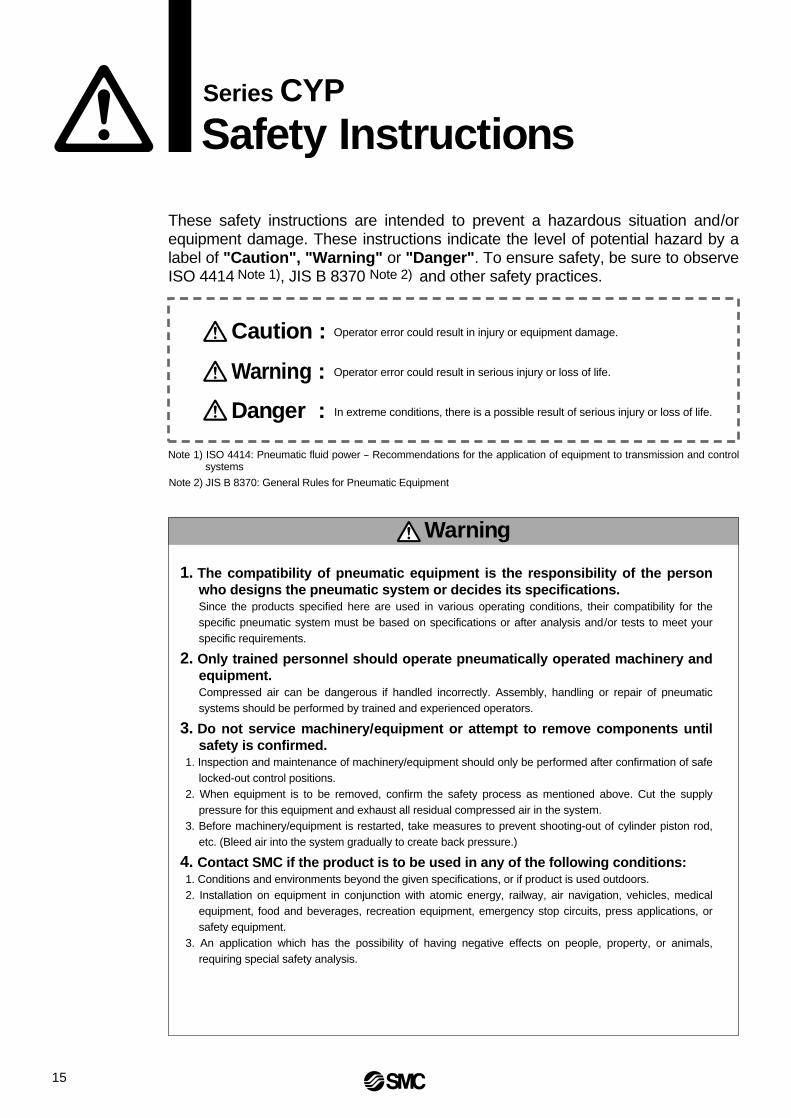
Safety Instructions
Note 1) ISO 4414: Pneumatic fluid power -- Recommendations for the application of equipment to transmission and control systems
Note 2) JIS B 8370: General Rules for Pneumatic Equipment
Warning
Caution : Operator error could result in injury or equipment damage.
Warning : Operator error could result in serious injury or loss of life.
Danger : In extreme conditions, there is a possible result of serious injury or loss of life.
These safety instructions are intended to prevent a hazardous situation and/or equipment damage. These instructions indicate the level of potential hazard by a label of "Caution", "Warning" or "Danger". To ensure safety, be sure to observe ISO 4414 Note 1), JIS B 8370 Note 2) and other safety practices.
1. The compatibility of pneumatic equipment is the responsibility of the person who designs the pneumatic system or decides its specifications.Since the products specified here are used in various operating conditions, their compatibility for the specific pneumatic system must be based on specifications or after analysis and/or tests to meet your specific requirements.
2. Only trained personnel should operate pneumatically operated machinery and equipment.Compressed air can be dangerous if handled incorrectly. Assembly, handling or repair of pneumatic systems should be performed by trained and experienced operators.
3. Do not service machinery/equipment or attempt to remove components until safety is confirmed.
1. Inspection and maintenance of machinery/equipment should only be performed after confirmation of safe locked-out control positions.
2. When equipment is to be removed, confirm the safety process as mentioned above. Cut the supply pressure for this equipment and exhaust all residual compressed air in the system.
3. Before machinery/equipment is restarted, take measures to prevent shooting-out of cylinder piston rod, etc. (Bleed air into the system gradually to create back pressure.)
4. Contact SMC if the product is to be used in any of the following conditions:1. Conditions and environments beyond the given specifications, or if product is used outdoors.2. Installation on equipment in conjunction with atomic energy, railway, air navigation, vehicles, medical
equipment, food and beverages, recreation equipment, emergency stop circuits, press applications, or safety equipment.
3. An application which has the possibility of having negative effects on people, property, or animals, requiring special safety analysis.
15

Series CYPActuator Precautions 1Be sure to read before handling.
1. Confirm the specifications.The products advertised in this catalog are designed according touse in industrial compressed air systems. If the products are used inconditions where pressure, temperature, etc., are out of specifica-tion, damage and/or malfunction may be caused. Do not use in theseconditions. (Refer to specifications.)
Consult SMC if you use a fluid other than compressed air.
2. Intermediate stopsWhen intermediate stopping of a cylinder piston is performed with a3 position closed center type directional control valve, it is difficult toachieve stopping positions as accurate and minute as with hydraulicpressure due to the compressibility of air.
Furthermore, since zero air leakages is not guaranteed, it may notbe possible to hold a stopped position for an extended period of time.Contact SMC in case it is necessary to hold a stopped position foran extended period.
1. Operate within the limits of the maximumusable stroke.Refer to the standard strokes for the maximum useable stroke.
2. Use a speed controller to adjust the cylinderdrive speed, gradually increasing from a lowspeed to the desired speed setting.
Precautions on Design Selection
Warning Warning
Caution
1. There is a danger of sudden action by aircylinders if sliding parts of machinery aretwisted, etc., and, changes in forces occur.In such cases, human injury may occur; e.g., by catching hands orfeet in the machinery, or damage to the machinery itself may occur.Therefore, the machine should be designed to avoid such dangers.
2. Install a protective cover when there is a riskof human injury.If a driven object and moving parts of a cylinder pose a danger ofhuman injury, design the structure to avoid contact with the humanbody.
3. Securely tighten all stationary parts andconnected parts so that they will notbecome loose.Especially when a cylinder operates with high frequency or isinstalled where there is a lot of vibration, ensure that all partsremain secure.
4. A deceleration circuit may be required.When a driven object is operated at high speed or the load isheavy, a cylinder’s cushion will not be sufficient to absorb theimpact. Install a deceleration circuit to reduce the speed beforecushioning to relieve the impact. In this case, the rigidity of themachinery should also be examined.
5. Consider a possible drop in operating pres-sure due to a power outage, etc.When a cylinder is used in a clamping mechanism, there is a dan-ger of work pieces dropping if there is a decrease in clampingforce due to a drop in circuit pressure caused by a power outage,etc. Therefore, safety equipment should be installed to preventdamage to machinery and/or human injury. Suspension mecha-nisms and lifting devices also require consideration for drop pre-vention.
6. Consider a possible loss of power source.Measures should be taken to protect against human injury andequipment damage in the event that there is a loss of power toequipment controlled by air pressure, electricity or hydraulics, etc.
7. Design circuitry to prevent sudden lurchingof driven objects.When a cylinder is driven by an exhaust center type directionalcontrol valve or when starting up after residual pressure isexhausted from the circuit, etc., the piston and its driven object willlurch at high speed if pressure is applied to one side of the cylin-der because of the absence of air pressure inside the cylinder.Therefore, equipment should be selected and circuits designed toprevent sudden lurching because, there is a danger of humaninjury and/or damage to equipment when this occurs.
8. Consider emergency stops.Design so that human injury and/or damage to machinery andequipment will not be caused when machinery is stopped by asafety device under abnormal conditions, a power outage or amanual emergency stop.
9. Consider the action when operation isrestarted after an emergency stop or abnor-mal stop.Design the machinery so that human injury or equipment damagewill not occur upon restart of operation. When the cylinder has tobe reset at the starting position, install safe manual control equip-ment.
16
Series CYPActuator Precautions 2Be sure to read before handling.
17
Operating Environment
Maintenance
Warning
1. Align carefully when connecting to a loadhaving an external guide mechanism.Since alignment variations increase as the stroke becomes longer, aconnection method (floating mechanism) should be consideredwhich can absorb these variations.
2. When an external guide is used, connect theexternal slider and the load in such a way thatthere is no interference at any point within thestroke.
3. Do not scratch or gouge the sliding parts ofthe cylinder tube by striking or grasping themwith other objects.Cylinder bores are manufactured to precise tolerances, so that evena slight deformation may cause malfunction.
4. Do not use until you verify that the equipmentcan operate properly.After mounting, repair or modification, etc., connect the air supplyand electric power, and then confirm proper mounting by means ofappropriate function and leak tests.
5. Instruction manualMount and operate the product after thoroughly reading the manualand understanding its contents.
Keep the instruction manual where it can be referred to as needed.
Mounting
Caution
Piping
Air Supply
1. Preparation before pipingBefore piping is connected, it should be thoroughly blown outwith air (flushing) or washed to remove chips, cutting oil andother debris from inside the pipe.
Caution
1. Use clean air.Do not use compressed air including chemicals, synthetic oilscontaining organic solvents, salt or corrosive gases, etc., as it cancause damage or malfunction.
1. Install air filters.Install air filters at the upstream side of valves. The filtrationdegree should be 5µm or finer.
2. Install an after cooler, air dryer or DrainCatch, etc.Air that includes excessive drainage may cause malfunction ofvalves and other pneumatic equipment. To prevent this, install anafter cooler, air dryer or Drain Catch, etc.
3. Use the product within the specified rangeof fluid and ambient temperature.Take measures to prevent freezing, since moisture in circuits willbe frozen under 5°C, and this can cause damage to seals andmalfunction.
Refer to SMC’s clean pneumatic series “Air Cleaning Equipment”catalog for further details on compressed air quality.
Warning
Caution
1. Do not use in environments where there is adanger of corrosion.Refer to the construction drawings regarding cylinder materials.
Warning
1. Perform maintenance according to the pro-cedure indicated in the instruction manual.Improper handling can cause malfunction and damage of machin-ery or equipment.
2. Removal of equipment and supply/exhaustof compressed air.When machinery is serviced, first check measures to preventdropping of driven objects and run-away of equipment, etc. Thencut off the supply pressure and electric power, and exhaust allcompressed air from the system.
When machinery is restarted, proceed with caution after confirm-ing measures to prevent lurching of actuators.
1. Drain flushing.Remove drainage from air filters regularly. (Refer to specifica-tions.)
Caution
18
1. Confirm the specifications.Read the specifications carefully and use this product appropri-ately. The product may be damaged or malfunction if it is usedoutside the range of specifications of current load, voltage, tem-perature or impact.
2. Take precautions when multiple cylindersare used close together.When multiple auto switch cylinders are used in close proximity,magnetic field interference may cause the switches to malfunc-tion. Maintain a minimum cylinder separation of 40mm. (When theallowable separation is indicated for each cylinder series, use thespecified value.)
3. Pay attention to the length of time that aswitch is ON at an intermediate stroke posi-tion.When an auto switch is placed at an intermediate position of thestroke and a load is driven at the time the piston passes, the autoswitch will operate, but if the speed is too great the operating timewill be shortened and the load may not operate properly. The max-imum detectable piston speed is:
V(mm/s) = x 1000
4. Keep wiring as short as possible.<Reed switch>As the length of the wiring to a load gets longer, the rush currentat switching ON becomes greater, and this may shorten the prod-uct’s life. (The switch will stay ON all the time.)
1) Use a contact protection box when the wire length is 5m or longer.
<Solid state switch>2) Although wire length should not affect switch function, use wiring
100m or shorter.
5. Take precautions for the internal voltagedrop of the switch.<Reed switch>
1) Switches with an indicator light (Except D-Z76)
• If auto switches are connected in series as shown below, takenote that there will be a large voltage drop because of internalresistance in the light emitting diodes. (Refer to internal volt-age drop in the auto switch specifications.)
[The voltage drop will be “n” times larger when “n” auto switch-es are connected.]
Even though an auto switch operates normally, the load maynot operate.
Design & Selection
WarningWarning
Auto switch operating range (mm)____________________________Time load applied (ms)
• In the same way, when operating at or below a specified volt-age, although an auto switch may operate normally, the loadmay not operate. Therefore, the formula below should be sat-isfied after confirming the minimum operating voltage of the
load.
2) If the internal resistance of a light emitting diode causes a prob-lem, select a switch without an indicator light (Model D-Z80).
<Solid state switch>3) Generally, the internal voltage drop will be greater with a 2 wire
solid state auto switch than with a reed switch. Take the same pre-cautions as in 1).
Also, note that a 12VDC relay is not applicable.
6. Pay attention to leakage current.<Solid state switch>With a 2 wire solid state auto switch, current (leakage current)flows to the load to operate the internal cir-
c u i teven
when in the OFF state.
If the criteria given in the above formula are not met, it will notreset correctly (stays ON). Use a 3 wire switch if this specificationwill not be satisfied.
Moreover, leakage current flow to the load will be “n” times largerwhen “n” auto switches are connected in parallel.
7. Do not use a load that generates surge volt-age.<Reed switch>If driving a load such as a relay that generates a surge voltage,use a contact protection box.
<Solid state switch>Although a zener diode for surge protection is connected at theoutput side of a solid state auto switch, damage may still occur ifthe surge is applied repeatedly. When a load, such as a relay orsolenoid valve, which generates surge is directly driven, use atype of switch with a built-in surge absorbing element.
8. Cautions for use in an interlock circuitWhen an auto switch is used for an interlock signal requiring highreliability, devise a double interlock system to avoid trouble by pro-viding a mechanical protection function, or by also using anotherswitch (sensor) together with the auto switch. Also perform peri-odic maintenance and confirm proper operation.
9. Ensure sufficient clearance for maintenanceactivities.When designing an application, be sure to allow sufficient clear-ance for maintenance and inspections.
Load
Supplyvoltage
Internal voltagedrop of switch
Minimum operatingvoltage of load
– >
Operating current of load (OFF condition) > Leakage current
Series CYPAuto Switch Precautions 1Be sure to read before handling.

19
Series CYPAuto Switch Precautions 2Be sure to read before handling.
5. Do not allow short circuit of loads.<Reed switch>If the power is turned ON with a load in a short circuit condition,the switch will be instantly damaged because of excess currentflow into the switch.
<Solid state switch>All models of PNP output type switches do not have built-in shortcircuit protection circuits. If loads are short circuited, the switcheswill be instantly damaged, as in the case of reed switches.
∗ Take special care to avoid reverse wiring with the brown (red)power supply line and the black (white) output line on 3 wire typeswitches.
6. Avoid incorrect wiring.<Reed switch>
∗ A 24VDC switch with indicator light has polarity. The brown (red)lead wire is (+), and the blue (black) lead wire is (–).
<Solid state switch>1) If connections are reversed on a 2 wire type switch, the switch will
not be damaged if protected by a protection circuit, but the switchwill be in a normally ON state. However, note that the switch willbe damaged if reversed connections are made while the load is ina short circuited condition.
∗ 2) If connections are reversed (power supply line + and power sup-ply line –) on a 3 wire type switch, the switch will be protected bya protection circuit. However, if the power supply line (+) is con-nected to the blue (black) wire and the power supply line (–) isconnected to the black (white) wire, the switch will be damaged.
7. Perform work on terminals before bringingthem into a clean room.Some lead wires contain white powder to prevent fusion of thesheath (covering) and core wire. In cases where this powder willbe a problem, perform cutting of lead wires, etc., before bringingswitches into a clean room. After removing powder which hasadhered to the insulating material, take steps to prevent dust fromescaping, such as wrapping the area near the cut in the sheathwith insulation tape, etc.
1. Do not drop or bump.Do not drop, bump or apply excessive impacts (300m/s² or morefor reed switches and 1000m/s² or more for solid state switches)while handling. Although the body of the switch may not be dam-aged, the inside of the switch could be damaged and cause a mal-function.
2. Do not carry a cylinder by the auto switchlead wires.Never carry a cylinder by its lead wires. This may not only causebroken lead wires, but it may cause internal elements of the switchto be damaged by the stress.
3. Mount switches using the proper tighteningtorque.When a switch is tightened beyond the range of tightening torque,the mounting screws, mounting bracket or switch may be dam-aged. On the other hand, tightening below the range of tighteningtorque may allow the switch to slip out of position. (Refer to switchmounting for each series regarding switch mounting, moving, andtightening torque, etc.)
4. Mount a switch at the center of the operatingrange.Adjust the mounting position of an auto switch so that the pistonstops at the center of the operating range (the range in which aswitch is ON). (The mounting positions shown in the catalog indi-cate the optimum positions at stroke end.) If mounted at the endof the operating range (around the borderline of ON and OFF),operation may be unstable.
Mounting & Adjustment Wiring
Wiring
Warning
1. Avoid repeated application of bending orstretching force to lead wires.Broken lead wires will result from repeatedly applying bendingstress or stretching force to the lead wires.
2. Be sure to connect the load before power isapplied.<2 wire type>If the power is turned ON when an auto switch is not connected toa load, the switch will be instantly damaged because of excesscurrent.
3. Confirm proper insulation of wiring.Be certain that there is no faulty wiring insulation (contact withother circuits, ground fault, improper insulation between terminals,etc.). Damage may occur due to excess current flow into a switch.
4. Do not wire with power lines or high voltagelines.Wire separately from power lines or high voltage lines, avoidingparallel wiring or wiring in the same conduit with these lines.Control circuits containing auto switches may malfunction due tonoise from these other lines.
Warning
Warning

20
Series CYPAuto Switch Precautions 3Be sure to read before handling.
1. Never use in an atmosphere of explosivegases.The construction of auto switches is not intended to preventexplosion. Never use in an atmosphere with an explosive gassince this may cause a serious explosion.
2. Do not use in an area where a magnetic fieldis generated.Auto switches will malfunction or magnets inside cylinders willbecome demagnetized.
3. Do not use in an environment with tempera-ture cycles.Consult SMC if switches are used where there are temperaturecycles other than normal temperature changes, as they may beadversely affected internally.
4. Do not use in an environment where there isexcessive impact shock.<Reed switch>When excessive impact (300m/s2 or more) is applied to a reedswitch during operation, the contact will malfunction and generateor cut off a signal momentarily (1ms or less). Consult SMC regard-ing the need to use a solid state switch depending upon the envi-ronment.
5. Do not use in an area where surges are gen-erated.<Solid state switch>When there are units (solenoid type lifter, high frequency induc-tion furnace, motor, etc.) which generate a large amount of surgein the area around cylinders with solid state auto switches, thismay cause deterioration or damage to internal circuit elements ofthe switches. Avoid sources of surge generation and disorganizedlines.
6. Avoid accumulation of iron debris or closecontact with magnetic substances.Note that if a magnetic substance (something attracted by a mag-net) is brought into close proximity with an auto switch cylinder, itmay cause auto switches to malfunction due to a loss of the mag-netic force inside the cylinder.
Operating Environment Maintenance
WarningWarning1. Perform the following maintenance periodi-
cally in order to prevent possible danger dueto unexpected auto switch malfunction.
1) Securely tighten switch mounting screws.
If screws become loose or the mounting position is dislocated,retighten them after readjusting the mounting position.
2) Confirm that there is no damage to lead wires.
To prevent faulty insulation, replace switches or repair lead wires,etc., if damage is discovered.
3) Confirm the lighting of the green light on a 2 color indicationswitch.
Confirm that the green LED is on when stopped at the establishedposition. If the red LED is on, the mounting position is not appro-priate. Readjust the mounting position until the green LED lightsup.
Other
Warning1. Consult SMC concerning elasticity of lead
wires and usage at welding sites, etc.
∗ Lead wire color changes
OldRed
Black
NewBrownBlue
Output (+)Output (–)
2 wireOldRed
BlackWhite
NewBrownBlueBlack
Power supplyGNDOutput
3 wire
Lead wire colors of SMC switches have been changed as shown below in order to meet NECA Standard 0402 for produc-tion beginning September, 1996 and thereafter. Special care should be taken regarding wire polarity during the time that the old colors still coexist with the new colors.

Mounting
Caution1. Take care to avoid striking the cylinder tube
with other objects or handling it in a way that could cause deformation.The cylinder tube and slider units have a non-contact construc-tion. For this reason, even a slight deformation or slippage of position can cause malfunction and loss of durability, as well as a danger of degrading the particulate generation characteristics.
2. Do not scratch or gouge the linear guide by striking it with other objects.Since the linear guide is specially treated for maximum suppres-sion of particulate generation due to sliding, even a slight scratch can cause malfunction and loss of durability, as well as a danger of degrading the particulate generation characteristics.
3. Since the slide table is supported by preci-sion bearings, do not apply strong impacts or excessive moment when mounting work piec-es.
4. Be sure to operate the cylinder with the plates on both sides secured.Avoid applications in which the slide table or only one plate is secured.
5. When changing the ports to be used, be sure that unused ports are securely sealed.Take sufficient care in sealing unused ports, because if ports are not properly sealed air can leak from the ports and particu-late generation characteristics can be degraded.
Handling
Caution1. Open the inner package of the double pack-
aged clean series inside a clean room or oth-er clean environment.
2. Perform parts replacement and disassembly work in a clean room after exhausting com-pressed air in the piping outside the clean room.
Operation
Caution3. When used for vertical operation, use caution
regarding possible dropping due to separa-tion of the magnetic coupling.When used for vertical operation, use caution as there is a pos-sibility of dropping due to separation of the magnetic coupling if a load (pressure) greater than the allowable value is applied.
4. Do not operate with the magnetic coupling out of position.If the magnetic coupling is out of position, push the external slider by hand (or the piston slider with air pressure) back to the proper position at the stroke end.
5. Do not supply lubrication, as this is a non-lube product.The interior of the cylinder is lubricated at the factory, and lubri-cation with turbine oil, etc., will not satisfy the product's specifi-cations.
6. Never reapply lubricant.Never reapply lubricant, as there may be a degradation of par-ticulate generation or operation characteristics.
Operation
Caution1. The maximum operating pressure for the
clean rodless cylinder is 0.3MPa If the maximum operating pressure of 0.3MPa for the clean rodless cylinder is exceeded, the magnetic coupling can be broken, causing a danger of malfunction or degradation of par-ticulate generation characteristics, etc.
2. The product can be used with a direct load applied within the allowable range, but care-ful alignment is necessary when connecting to a load having an external guide mechan-ism.Since alignment variations increase as the stroke gets longer, use a connection method which can absorb these variations and consider measures to control particulate generation.
Speed Adjustment
Caution1. A throttle valve for clean room use is recom-
mended for speed adjustment. (Consult SMC regarding equipment and methods to be used.)Speed adjustment can also be performed with a meter-in or meter-out type speed controller for clean room use, but it may not be possible to obtain smooth starting and stopping opera-tion.
2. In case of vertical mounting, a system with a reduced pressure supply circuit installed on the down side is recommended. (This is ef-fective against upward starting delays and for conservation of air.)
10-AS1200-M5-X216
10-AS1000-M5-X214
10-AS1201F-M5-04-X214
10-AS1201F-M5-06-X214
10-AS1301F-M5-04-X214
10-AS1301F-M5-06-X214
10-AS1001F-04-X214
10-AS1001F-06-X214
10-ASD230F-M5-04
10-ASD230F-M5-06
10-AS2200-01-X214
10-AS2000-01-X209
10-AS2201F-01-04-X214
10-AS2201F-01-06-X214
10-AS2201F-01-06-X214
10-AS2301F-01-04-X214
10-AS2301F-01-06-X214
10-AS2301F-01-06-X214
10-AS2001F-04-X214
10-AS2001F-06-X214
10-ASD330F-01-06
10-ASD330F-01-08
Metal bodypiping type
Resin bodywith
One-touchfitting
Universal type (throttle valve)
In-line type (throttle valve)
Dual type(speed controller)
Elbow type (throttle valve)
Elbow type
In-line type
Model
CYP15 CYP32Series
Throttle valve
Throttle valves and dual speed controllers for recommended speed adjustment of CYP cylinders
Series CYPSpecific Product Precautions 1Be sure to read before handling.
21

Series CYPSpecific Product Precautions 2Be sure to read before handling.
22
Maintenance
Caution1. Never disassemble the cylinder tube or linear
guide, etc.If disassembled, the slide table may touch the outside surface of the cylinder tube resulting in a degradation of particulate gener-ation characteristics.
2. Consult SMC when replacing seals and bearings (wear rings).
Cushion Effect (Sine Cushion) and Stroke Adjustment Particulate Generation Characteristics
Caution1. A sine cushion (smooth start, soft stop) func-
tion is included in the standard specifica-tions.Due to the nature of a sine cushion, adjustment of the cushion effect is not possible. There is no cushion needle adjustment as in the case of conventional cushion mechanisms.
2. The stroke end adjustment is a mechanism to adapt the slide table's stroke end position to a mechanical stopper on other equipment, etc.(Adjustment range: Total of both sides ±2mm) To ensure safety, perform adjustment after shutting off the drive air, releasing the residu-al pressure and implementing drop preven-tion measures, etc.1) Loosen the inner cover holding screw with a hexagon
wrench, etc.2) To match the position with a mechanical stopper on other
equipment, etc., rotate the stroke adjustment screw (inner cover) to the left or right with a flat head screw driver to move the inner stopper back and forth. Approximately 1mm of ad-justment is possible with one rotation.
3) The maximum adjustment on one side is ±1mm. A total ad-justment of approximately ±2mm is possible using both sides.
4) After completing the stroke end adjustment, tighten the inner cover holding screw with a hexagon wrench, etc.
Caution1. In order to maintain the particulate
generation grade, use operation of 500 thousand cycles or travel distance of about 400km as a standard. (Table 1 below)If operation is continued beyond the recommended values, lubrication failure of the linear guide and loss of particulate generation characteristics may occur.
Stroke adjustment screw(inner cover)
Inner coverholding screw
Flat head screw driver
+direction
Plate
– direction
Hexagonwrench
10⁰
0.01 0.1 1 10
10¹
10²
10³
10⁴
10⁵
Class M3.5 [Class100]
Class M2.5 [Class10]
Class M1.5 [Class1]
Stroke (mm)
Tota
l ope
ratio
n cy
cles
(10
,000
)
10
20
30
40
50
100
100 200 300 400 500 700 1000
Table 1
Table 2
Model
CYP15
CYP32
Screw size
M3 x 0.5
M6 x 1
Tightening torque
0.3
2.45
Inner cover holding screw tightening torque [N⋅m]
Particle diameter (µm)
Par
ticle
con
cent
ratio
n (p
artic
les/
m³)
Note 1) This chart indicates the level of cleanliness inside the measurement chamber.
Note 2) The vertical axis shows the number of particles per unit volume (1m³) of air which are no smaller than the particle size shown on the horizontal axis.
Note 3) The gray lines show the upper concentration limit of the cleanliness class based on Fed. Std. 209E-1992.
Note 4) The plots indicate the 95% upper reliability limit value for time series data up to 500 thousand operation cycles. (Cy-linder: CYP32-200, Work piece weight: 5kg, Average speed: 200mm/s)
Note 5) The data above provides a guide for selection but is not guaranteed.


EUROPESPAIN/PORTUGALSMC España, S.A.
SWEDENSMC Pneumatics Sweden AB
SWITZERLANDSMC Pneumatik AG.
UKSMC Pneumatics (U.K.) Ltd.
ASIACHINASMC (China) Co., Ltd.
HONG KONGSMC Pneumatics (Hong Kong) Ltd.
INDIASMC Pneumatics (India) Pvt. Ltd.
MALAYSIASMC Pneumatics (S.E.A.) Sdn. Bhd.
PHILIPPINESSMC Pneumatics (Philippines), Inc.
SINGAPORESMC Pneumatics (S.E.A.) Pte. Ltd.SOUTH KOREASMC Pneumatics Korea Co., Ltd.
TAIWANSMC Pneumatics (Taiwan) Co., Ltd.
THAILANDSMC Thailand Ltd.
NORTH AMERICACANADASMC Pneumatics (Canada) Ltd.
MEXICOSMC Corporation (Mexico) S.A. de C.V.USASMC Pneumatics, Inc.
SOUTH AMERICAARGENTINASMC Argentina S.A.
BOLIVIASMC Pneumatics Bolivia S.R.L.
BRAZILSMC Pneumaticos Do Brazil Ltda.
CHILESMC Pneumatics (Chile) S.A.
VENEZUELASMC Neumatica Venezuela S.A.
OCEANIAAUSTRALIASMC Pneumatics (Australia) Pty. Ltd.
NEW ZEALANDSMC Pneumatics (N.Z.) Ltd.
EUROPEAUSTRIASMC Pneumatik GmbH
CZECHSMC Czech s.r.o.
DENMARKSMC Pneumatik A/S
FINLANDSMC Pneumatiikka OY
FRANCESMC Pneumatique SA
GERMANYSMC Pneumatik GmbH
HUNGARYSMC Hungary Kft.
IRELANDSMC Pneumatics (Ireland) Ltd.
ITALYSMC Italia S.p.A.
NETHERLANDSSMC Pnuematics BV.
NORWAYSMC Pneumatics Norway A/S
ROMANIASMC Romania s.r.l.
RUSSIA SMC Pneumatik LLC.
SLOVAKIASMC Slovakia s.r.o.
SLOVENIASMC Slovenia d.o.o.
SMC'S GLOBAL MANUFACTURING, DISTRIBUTION AND SERVICE NETWORK
1-16-4 Shimbashi, Minato-ku, Tokyo 105-0004, JAPANTel: 03-3502-2740 Fax: 03-3508-2480URL http://www.smcworld.com© 1999 SMC CORPORATION All Rights Reserved
Specifications are subject to change without prior notice and any obligation on the part of the manufacturer.
Printed in Japan.1st printing December, 1999 D-SMC.L.A. P-80 (D)