clean combustion system™ (ccs) retrofit of power boilers
TRANSCRIPT

Clean Combustion System™ (CCS) Retrofit
of Power Boilers for SO2 and NOx Control
with Improved Efficiency
CCS Re Engineering Proposal - Phase 1 Concept
Study
By:
CastleLight Energy Corp.
3401 W. 5th
Street, Suite 200
Oxnard, CA 93030
PHONE: (805) 551-0983
E-mail: [email protected]
Web Site: www.Castle-Light.com
Dated: August 9, 2016

CCS Re Engineering Proposal - Phase 1 Study
Confidential Business Information of Castle Light Energy Corp
i of 24
CONTENTS
1. INTRODUCTION 3
1.1 PHASE I PROPOSAL OBJECTIVES 3
1.2 CCS RETROFIT PROGRAM 4
1.3 CCS TECHNOLOGY TECHNICAL APPROACH: 4
2. CCS EMISSIONS PERFORMANCE SUMMARY 9
3. CCS TECHNOLOGY MATURITY 11
4. .CCS RETROFIT APPROACH 13
4.1 SUMMARY OF PROJECT PHASES 13
4.2 CCS RETROFIT INSTALLATION 13
4.3 MODELING OF BOILER MODIFICATIONS 15
5. PHASE 1 - SCOPE OF WORK 16
5.1 TASK A: PROJECT KICK-OFF MEETING 16
5.2 TASK B: DEVELOP CCS REQUIREMENTS: 16
5.3 TASK C: BOILER MODIFICATIONS AND EQUIPMENT SCOPE 16
5.4 TASK D: BALANCE OF PLANT 17
5.5 TASK E: DELIVERABLES 17
5.6 PHASE 1 SCHEDULE 18
6. PROJECT TEAM 20
6.1 PROJECT MANAGEMENT ORGANIZATION 20
6.2 CAPABILITIES OF CASTLELIGHT ENERGY CORP. 20
6.3 PROPRIETARY PROGRAM 21
7. APPENDIX A INFORMATION NEEDED FROM PLANT SITE 23


CCS Re Engineering Proposal - Phase 1 Study
Confidential Business Information of Castle Light Energy Corp
3 of 24
1. INTRODUCTION
Castle Light Energy Corp, a technology management firm located in Oxnard,
California, is pleased to propose a Phase I Concept study to re-engineer a coal-fired
power boiler with the Clean Combustion System™ (CCS).
The CCS emissions performance objective for this program is to up-date a power plant
firing PRB Sub bituminous coals to meet the strict EPA air quality regulations for SO2
emissions (<0.2 Lb. SO2 / MMBtu), NOx emissions (< 0.1 Lb. NOx/ MMBtu), and to
improve the boiler efficiency to meet the proposed EPA Clean Power Plan for CO2
reduction (~6%). An existing bag house or ESP is to provide particulate control.
The Clean Combustion System (CCS) is a patented field-demonstrated combustion
technology that provides coal-fired electric generating plants control of SO2, SO3, and
NOx emissions right in the combustion step. The CCS features improved boiler efficiency
(reduced CO2) and minimizes ash and corrosion deposits on the furnace wall and back-
pass sections. There are no hazardous or toxic chemicals or water requirements. The
only “chemical” required is limestone. As the CCS technology installation qualifies as an
emissions reduction program, construction permits are available with waivers of NSPS &
PSD and no New Source Review (NSR) trigger.
The CCS technology was developed from fundamental combustion theory at Rockwell
International in the 80’s with some $60 million in utility pier reviewed R&D testing and
field-demonstration operation. The CCS may retrofit nearly all boilers types including
cyclone, wall-fired, tangential and stoker, and is capable of converting gas and oil-fired
boilers to coal firing.
The CCS installation costs are expected to be less than one-third the cost of conventional
SCR/ammonia system (for NOx control) and an FGD/limestone scrubber system (for SO2
control). A CCS re engineered plant promises to provide the boiler owner / operator
emissions compliance and many more years of competitive dispatch operation. .
1.1 PHASE I PROPOSAL OBJECTIVES
The Phase I retrofit study objectives are to:
1.) Confirm the CCS technology will meet the boiler owner’s emissions and
performance targets with the selected coal,
2.) Collect project and site information, documentation, fuel specifications and boiler
specifications and drawings to develop the appropriate CCS retrofit design (see
Appendix A - List of Information Needed),
3.) Review the boiler and plant facility to fit and accommodate the CCS equipment,
4.) Prepare recommendations for the engineering, design and hardware supply.
5.) Deliver a CCS re-engineering proposal and cost estimate.

CCS Re Engineering Proposal - Phase 1 Study
Confidential Business Information of Castle Light Energy Corp
4 of 24
1.2 CCS RETROFIT PROGRAM
A CCS retrofit is a custom modification of the coal-fired boiler and its coal preparation
equipment. A retrofit entails the engineering, design and analysis to facilitate:
o The removal the existing burners and wind box, including the burner water-wall
section of the boiler,
o The addition of new larger fabricated ports to the boiler water-wall.
o Installation of the new CCS burners and gasification chamber(s) to fire through
the new ports on the boiler,
o Addition of new over-fire air ducting and ports to the boiler as required,
o Modify the existing pulverized coal system to an “indirect fired” system,
o Add new pulverized coal metering feeders to the CCS burners.
o Equipment to meter powdered limestone to the coal pulverizers,
o Modify / add a new slag/bottom ash collection/disposal system,
o Revisions to the Operator HMI Panel; Burner Management and Plant DCS
controls and instrumentation as required for the new CCS equipment, including
revisions to the MCC.
1.3 CCS TECHNOLOGY TECHNICAL APPROACH:
1.3.1 Coal Preparation and Drying:
The CCS fires standard grind powdered coal (70% through 200 mesh) from the plant’s
coal mill(s). Powdered limestone is metered to the mill at a rate of ~100 pounds CaCO3
per Ton of coal. Typical sub bituminous PRB coals contain ~30% water. For improved
combustion efficiency and to reduce CO2 emissions, we will dry the coal to remove surface
water.
Recall that the conventional
“direct-fired” boiler uses hot air
from the air pre-heater to
provide the primary combustion
air that conveys the coal through
coal-mill(s) and to the burner(s).
However, as the CCS
gasification process requires
much less combustion air than
typical coal burners, we must
first convert the coal mill to an
“indirect fired system”. See
Figure 1.
Figure 1. Indirect Coal Firing System

CCS Re Engineering Proposal - Phase 1 Study
Confidential Business Information of Castle Light Energy Corp
5 of 24
We will add a small bag house to each coal mill and re-direct the pulverized coal and
sweep gas to the bag house; to separate the powdered coal from the sweep gas. Also,
rather than use hot air primary air as the mill sweep gas, we will extract hot, inert flue-
gas (oxygen <10%) from the plants exhaust. As the coal is pulverized, the very hot sweep
gas evaporates the coal’s surface moisture, drying the fine coal particles to <10%
moisture. Our coal-drying process is very fast (about one second) and prevents fire and
puffs for safer mill /bag house operation.
The dry powdered coal is then collected in the bag house hopper and directly metered and
conveyed to the CCS burners as required to meet plant load. The coal’s residence time in
the bag house hopper is limited to <15 minutes. The now cool and wet sweep gas from
the bag house is rerouted around the furnace to the plant’s exhaust.
By removing the coal moisture from the furnace, we improve the coal’s quality (Btu/Lb
values) for improved combustion efficiency (reduces latent heat water loss), reduced coal
consumption and CO2 emissions. For the sub bituminous PRB type coals, this step can
meet EPA’s “Clean Power Plan” for CO2 reduction of ~6%. The estimated cost of this
modification is ~ $30/kW, plus installation.
1.3.2 CCS Working Principle:
Described as a “Hybrid of Coal-
Gasification” and “Over Fire Air Staged
Combustion” process, the CCS replaces the
boiler’s existing coal-burners and wind box
with the same number of new CCS
Burners.
The CCS burners fire into one or more
Gasification Chambers that are mounted
directly on the boiler’s water-wall
(replacing the wind-box & burners). See
Figure 2. CCS Schematic.
The Gasification Chamber(s), formed of
studded and refractory lined water-wall,
provides the necessary fuel-rich
combustion conditions and residence time
(fractions of a second) required for the CCS
sulfur capture and NOx destruction
process.
The gases exit from the Chamber directly
into the bottom of the boiler furnace.
Figure 2. CCS Schematic

CCS Re Engineering Proposal - Phase 1 Study
Confidential Business Information of Castle Light Energy Corp
6 of 24
All of the CCS equipment and instrumentation is familiar to the operators. The boilers
start-up, shut down, and burner and mill out-of-service procedures will remain the same
as before the modifications.
1.3.3 Carbon Oxidation:
All of the pulverized coal and limestone is metered to the CCS burners with a limited
quantity of hot air. The coal lights off and quickly consumes all available oxygen, to
create a hot, very-fuel-rich gas. Sufficient residence time is provided in the Gasification
Chamber for the combustion kinetics and chemistry to reach equilibrium. In this very-
fuel-rich environment, the hot carbon particles are aggressive for oxygen from any
source,
including water and carbon dioxide (H2 O & CO2). As this is an endothermic
process, gas temperatures will tend to drop. The result is a clear hot bright orange gas of
nitrogen (N2), carbon monoxide (CO), and hydrogen (H2), with some free carbon particles
that exits the chamber into the furnace section.
1.3.4 Sulfur Capture in Combustion:
Engineers are aware that sulfur can be captured right in the initial coal combustion step.
The fluidized bed combustor (FBC) is a well known commercial process which burns coal
at rather low temperatures (~1600F) in a bed of sand and limestone, fluidized with hot
combustion air. As the carbon is oxidized and creates heat, the calcium from the
limestone captures the sulfur in the coal (as calcium sulfate - CaSO4). The FBC
combustion process is rather slow, requiring several seconds of residence time to burn
the coal. The FBC combustion process requires large horse power, high pressure air
blowers to circulate the bed. The FBC is limited boiler size (<200 MW) and suffers lower
combustion efficiencies. It is best suited to fire low quality, high sulfur fuels.
However by comparison, the CCS is a fast, very fuel-rich sulfur capture process. As the
carbon is oxidized, the sulfur is released from the coal into the hot gasses. Normally,
under fuel-rich combustion, the sulfur would form a hydrogen sulfide (H2S) compound.
However, as we have added calcium to the coal (as limestone), the calcium beats out
hydrogen for the sulfur, and forms calcium sulfide (CaS), a solid particle even at these
high temperatures. Note that if any oxygen were to later contact the CaS, this compound
oxidizes to SO2.
1.3.5 Coal Ash and Sulfur Disposal:
To complete the sulfur capture process, we have learned how to generate sufficiently
high temperatures that cause the coal ash (silica - SiO2, and alumina - Al2O3), to mix
with the calcium sulfide (CaS) and melt. You may recall that the formula for glass is;
silica, alumina and calcium oxide (CaO). However, since we have substituted sulfur for
the oxygen (in the CaS) the products melt together and encapsulate the sulfur in the
liquid glass (ash/slag) product. The sulfur is bound tightly in the slag product and will
not leach into water. About half of the melted ash contacts the walls of the gasification
chamber and drain as bottom ash into a water quench tank for disposal. This slag
CCS Re Engineering Proposal - Phase 1 Study
Confidential Business Information of Castle Light Energy Corp
7 of 24
product has commercial values (~ $3/T) and is suitable for grit blasting metal, roof grit,
etc. The remaining fine ash droplets are carried into the furnace section and become fly
ash.
1.3.6 NOx Formation and Destruction:
In coal combustion, the nitrogen in the coal (typically ~ 1%) is the major source of NOx
(~85%) in power plant flue-gas. NOx formed from the high temperature oxidation of
nitrogen (>2300F) in the combustion air; so called “thermal” NOx. comprise the balance.
In the late 70’s, combustion research at Rocketdyne by Dr. Axworthy showed that the
nitrogen in the coal forms NOx, or the precursors of NOx - such as ammonia (NH3), and
cyanide (HCN), at the same time and place as the carbon is oxidized. Further, he
demonstrated that this fuel-NOx formation process cannot be avoided; such as with low
temperature combustion processes, as used to avoid thermal NOx formation when firing
natural gas.
However, careful observations of Fluid Bed Combustion (FBC) showed that something
was effectively reducing the fuel-NOx levels in the bed. And a theory evolved to look for a
NOx destruct catalysis that may be found in the combustion step. A lab furnace was set
up to duplicate the FBC combustion bed conditions. The minerals and compounds found
in coal were exposed to NOx under combustion conditions and any change in NOx inlet /
outlet levels were noted. It was determined that calcium sulfide (CaS) was a gang
buster NOx destruct catalysis, especially under the fuel-rich, high-temperature
conditions such as found in an FBC bed.
This was a remarkable discovery, as Rockwell was developing a new coal-fired burner for
SO2 control; with fuel-rich combustion featuring sulfur capture with calcium.
Calcium sulfide is a very reactive compound; it quickly oxidizes to H2S in air, so it must
be created when and where needed.
In the 1 T/hr R&D burner development, we observed that the CaS destroyed fuel-NOx to
“single digit ppm levels” right in the initial combustion step – only some 30 inches from
the burner face.
Rockwell now had a new coal-fired burner concept with SO2 capture that included
synergistic NOx destruction …………….at no extra charge nor toxic chemicals required!
1.3.7 Boiler Furnace Over Fire Air (OFA) Staged Combustion:
The hot fuel-rich gases of N2, CO, and H2 exit the gasification chamber into the boiler
furnace where the relatively “cold, water cooled walls” begin to cool the gases and
generate steam. As we are concerned for and wish to avoid any “thermal NOx formation,
so we must wait for the gasses to cool to <2300F. At these temperatures, any ash
droplets carried over quickly solidify to form fly ash (~10 micron) particles.

CCS Re Engineering Proposal - Phase 1 Study
Confidential Business Information of Castle Light Energy Corp
8 of 24
We can then carefully stage over-fire-air into the furnace with a multiple of ports to
complete the combustion of CO to CO2 and H2 to water with sufficient air to exit the
furnace into the boiler’s back pass (super heater section) at ~ 3% O2 and at the same
design conditions as was before the CCS retrofit. A clear bright orange gas, free of
flame fills the furnace. The furnace walls are clean, without slagging, fouling and
corrosive sulfur deposits. An ESP or bag house provides the necessary final particulate
control before the smoke stack.
The Figure 3. CCS Retrofit Concept shows a cross-section of a CCS modification of a wall-
fired boiler design. The wind box and burners are replaced with factory manufactured water-
wall sections and new CCS Burners. Over fire air ports are added to the furnace to complete
the combustion in the furnace section. The bottom ash system is modified to collects bottom
ash for disposal.
Figure 3. CCS Boiler Retrofit

CCS Re Engineering Proposal - Phase 1 Study
Confidential Business Information of Castle Light Energy Corp
9 of 24
2. CCS EMISSIONS PERFORMANCE SUMMARY
2.1.1 SO2 Emissions Control:
When burning low-rank
sub-bituminous type coals
(Wyoming Powder River
Basin), the CCS has
demonstrated control of
sulfur dioxide (SO2)
emissions to low levels (<0.2
lb. SO2/MMBtu or ~105
ppm). See Figure 4.
Notice that as the sulfur has
been removed, there is near-
zero SO3 in the exhaust
gasses, enabling lower
furnace exit temperatures
for improved plant
efficiency.
The CCS carbon conversion
to energy is excellent, with
very little carbon (LOI) in
the final fly ash product. Figure 4. SO2 and NO x Emissions
LNS-CAP -3 Ton/hr Pilot Plant:
Western Sub bituminous Coal
2.1.2 NOx Emissions Control:
The CCS synergistic NOx destruction process, resulting from sulfur capture as described
herein, reliably demonstrates very low NOx emissions for all coals: :
Low NOx/SOx Coal Application Plant (LNS-CAP)- Cold Lake, Alberta, Canada:
3 T/hr. : firing western sub-bituminous coal – see Figure 4.<0.15 Lb NOx /MMBtu
(<110ppm NOx )
Industrial Stoker Boiler, Cario, IL, USA:
30 MWT firing high sulfur Illinois coal;
@ < 90% MCR; 0.04 to 0.07 Lb NOx /MMbtu (30 to 50 ppm NOx ,)
@ 100 % MCR; 0.12 Lb NOx /MMBtu ( ~0.88 ppm NOx)
2.1.3 CO2 Emissions Reduction & Fuel Cost Savings:
Western sub bituminous PRB type coals contain ~30% water. As discussed earlier,
drying the coal provides a significant combustion efficiency improvement with reduced

CCS Re Engineering Proposal - Phase 1 Study
Confidential Business Information of Castle Light Energy Corp
10 of 24
CO2 emissions. This performance directly addresses EPA’s CLEAN POWER PLAN
requiring CO2 reduction for coal-fired powered plants. As an example, for a 600 MW
plant firing PRB coals dried to ~9% moisture:
Btu/lb (HHV) = 10,667: Improved 26%
Boiler Efficiency: Improved 3.0%
CO2 Emissions: Reduced 4.2%
Coal Consumption: Reduced 483,000 T/yr
Fuel Cost Savings @ $30/T $14 million/yr
2.1.4 Commercial Retrofit Project: 30 MWT CCS Stoker
© Boiler
Phenix Limited, LLC, the predecessor to CastleLight Energy, contracted to re-engineer a
1940’s industrial Stoker boiler to fire low-cost, high-sulfur Illinois coal with SO2 and NOx
control. The contract scope included the CCS process design & engineering and to supply
the project with all the equipment, hardware, electrical, instrumentation and controls
with a limited commercial warrantee & license. The plant owner installed the
equipment.
This project was completed on time and on budget and commenced commissioning. As a
first of a kind project, it took time to sort out the details, particularly related to ease of
start up. The operators were able to demonstrate a cold start up to full load operation in
five hours from the HMI panel. This project provided a lot of experience and data and
confirmed the potential of the CCS process.
Around this time, the cost of natural gas dropped. The owner decommissioned the CCS
boiler and installed a NG fired boiler.
For more details about this project, please see the paper titled; “OPERATING EXPERIENCE
OF A COAL-FIRED BOILER RETROFIT WITH AN ADVANCED HYBRID OF COAL GASIFICATION FOR SO2 &
NOx EMISSIONS CONTROL AND REDUCED OPERATING COST”
2.1.5 Ash Deposition on Furnace Walls:
About one-half of the coal ash from the CCS
gasification chamber passes through the
furnace as a dry, fine particulate fly ash.
Figure 5. shows the CCS-Stoker© Furnace Ash
deposition after about 6 months of operation.
Notice that the CCS ash does not deposit on the
furnace water walls or back pass sections.
Nearly all the ash product was conveyed to the
boilers bag house. Very little fly ash collected
in the stoker’s back pass ash hoppers. About
three inches of dust covered the boiler floor. .
Figure 5. CCS-Stoker© Furnace Ash Deposition

CCS Re Engineering Proposal - Phase 1 Study
Confidential Business Information of Castle Light Energy Corp
11 of 24
3. CCS TECHNOLOGY MATURITY
3.1.1 CCS- Boiler Retrofit
As an example of a CCS retrofit, Figure 6. CCS Power Boiler Retrofit (3
View) shows a typical 600 MW
opposed-wall electric generating power
plant.
In this example, the 24 coal-burners
will be removed, and the burner ports
bricked over or reconfigured as CCS
over-fire air ports.
The wind box and ducting (green) will
be removed, leaving the boiler water
walls. (The SCR unit is not required)
To re-engineer this unit with the CCS,
24 new CCS Burners mounted on six
new CCS Gasification Chambers will
be pre-fabricated at a boiler shop and
delivered ready for installation.
Openings for the CCS Gasification
Chamber(s) will be saw-cut through
the furnace hopper water-wall section.
The CCS Gasification Chamber
assembly will be inserted into the
openings. Bottom ash is collected
from each GC section.
New fabricated water-wall sections
will connect the openings in the
furnace to maintain the furnace
water-wall cooling flow as before.
Much of the boilers air combustion air
will be ducting to new OFA ports in
the upper furnace walls.
Figure 6. CCS Power Boiler Retrofit (3 View)

CCS Re Engineering Proposal - Phase 1 Study
Confidential Business Information of Castle Light Energy Corp
12 of 24
3.1.2 CCS-Tangential© Boiler Retrofit
CastleLight developed a proposal for Indianapolis Power & Light to participate in a
Department of Energy Clean Coal Technology demonstration. The CCS technology was
to be installed on their 100 MW Unit #6 tangential boiler at the Harding Street Station.
At that time, the retrofit approach was to add two CCS gasification chambers, one on
each side of the furnace, each with 8 CCS burners, replacing the existing tangential
burners on the four corners. OFA was to be provided by the SOFA and corner ports. See
Figure 7. CCS-Tangential© Boiler Retrofit Concept.
Figure 7. CCS-Tangential© Boiler Retrofit Concept

CCS Re Engineering Proposal - Phase 1 Study
Confidential Business Information of Castle Light Energy Corp
13 of 24
4. .CCS RETROFIT APPROACH
4.1 SUMMARY OF PROJECT PHASES
Figure 8. entitled “CCS Retrofit Project
Flow Diagram” illustrates the steps
planned to complete a CCS retrofit
installation on a power boiler.
CastleLight will report to the Client’s
designated Project Manager as the CCS
technology manager. CastleLight will
supply the proprietary CCS technology,
engineering, design, analysis (including
advanced CFD and PEPSE), and will
supply the hardware and instrumentation
needed to modify the boiler.
The client is responsible for all on site
activity, including demolition,
construction and installation services, as
required to install the CCS hardware.
CastleLight will provide onsite support
during the construction through to the
plants start-up and commissioning, so as
to assure the CCS is properly installed.
This proposal is for a Phase I “Retrofit
Study” only.
Figure 8. CCS Retrofit Project Flow Diagram
4.2 CCS RETROFIT INSTALLATION
CastleLight will work closely with Client’s during the engineering phase to coordinate a
well-planned CCS retrofit, and proactively identify outage issues and installation cost
estimates.
The estimated cost for a CCS retrofit vary, primarily due to site-specific issues, but are
modest when compared to typical FGD and SCR installations. The CCS Retrofit of the
furnace are largely modifications to the water-wall, and familiar to the boiler
manufacturer. The design concept show nearly all of the modifications can fit within the
existing boiler and wind box area.
PHASE 1
Retrofit Study90 Days
PHASE II
Engineering & CFD 150 Days
Commission
CCS-Boiler Retrofit
PHASE III
Retrofit InstallationScheduled to fit Boiler outage
Contractor
Boiler, I&C Specialist
CFD Analysis
Boiler Mfg.
Contractor
Boiler Mfg.
Contractor
Boiler Mfg.
PHENIX LIMITED, LLC
Power Plant Owner / OperatorDesignate Boiler & Specify Coal
CastleLight Energy
Re-Engineering Coal-Fired Power Plants with the Clean Combustion System
CASTLE LIGHT ENERGY CORP
CCS Re Engineering Proposal - Phase 1 Study
Confidential Business Information of Castle Light Energy Corp
14 of 24
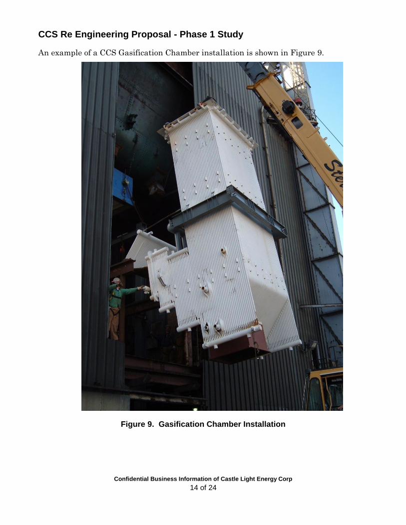
An example of a CCS Gasification Chamber installation is shown in Figure 9.
Figure 9. Gasification Chamber Installation

CCS Re Engineering Proposal - Phase 1 Study
Confidential Business Information of Castle Light Energy Corp
15 of 24
4.3 MODELING OF BOILER MODIFICATIONS
The first step in Phase I study will be to develop a detailed 3 view model of the furnace
and plant, complete with all major piping and building structures. This model enables
the design and evaluation the CCS modifications and the assessment of any interferences
or installation issues. CFD and PEPSE programs are used assess the heat transfer
affects from adding the new CCS gasification chamber to the boiler steam circuits. We
use CFD modeling extensively to determine how best to locate new OFA (over-fire air)
ports in the furnace. We assess CO combustion and any potential for new NOx
formation. CFD also addresses boiler operation at different load profiles to assure that
the gas temperatures entering the boiler superheat section are the same as before
retrofit.
4.4 OUTAGE PLAN
The key to minimize retrofit cost is to schedule the work around the boilers annual
outage, as loss of power production equates as an added cost to the retrofit. Therefore,
project planning and engineering will focus on minimizing the retrofit outage period.
A detailed inspection will be conducted to assess any onsite issues typically not shown on
drawings. A Base Line performance test is conducted to develop needed design
information.
Before the outage, and while the unit is still in operation, supports and braces will be
installed to hold major boiler sections in place during the modifications. Monorails and
lifting gear will be installed. Other equipment, such as the limestone preparation and
ash handling systems can be installed and checked out. The required CCS retrofit
hardware, such as the CCS burners, water wall modifications, OFA ports and ducting,
bottom ash equipment, etc. will be shop fabricated and delivered to the site.
During a scheduled outage, the existing PC burners, and portions of the boiler water-
wall and wind-box ducting are removed. Shop-fabricated CCS burners, a new
gasification chamber assemblies, ducting, OFA ports, etc. are delivered to minimize the
boiler outage schedule. During the retrofit project, the new hardware is moved into place
and welded to the existing water-wall, along with the new over-fire air ports and ducting,
according to design specifications.
The actual retrofit then is a carefully scheduled sequence of boiler water-wall
modifications, wherein existing air ducting and water-wall sections are cut away and
removed. As a section is removed, the new shop fabricated water-wall sections are
maneuvered to match the existing tubing and welded. This sequence will minimize the
requirements for support and bracing of the remaining boiler. Typical boiler water-wall
replacement schedules take about three weeks, scheduled with two 10-hour shifts per
day, six days a week with Sundays off.

CCS Re Engineering Proposal - Phase 1 Study
Confidential Business Information of Castle Light Energy Corp
16 of 24
5. PHASE 1 - SCOPE OF WORK
CastleLight proposes to conduct a Phase I Study to retrofit the CCS technology on a
selected coal-fired power boiler firing a selected coal. The Phase I study is planned as a
thirteen week program (after receipt of plant data - see Figure 3 titled “CCS Retrofit
Phase I Schedule”) that comprise the following tasks:
5.1 TASK A: PROJECT KICK-OFF MEETING
Castle Light will conduct an on-site kick-off meeting and briefing of the client’s
management team. This meeting is a forum for the management teams; to clarify the
project goals and objectives, define individual responsibilities and reporting roles, review
the contract to reaffirm all tasks and assumptions previously made, and make
appropriate changes to obtain mutual commitments to the project’s success.
The first step for CastleLight is to gather all relevant boiler specifications, drawings,
operating procedures and schematics applicable to the project. Addendum A list the
information needed. The next step is to conduct an engineering analysis and develop a
CCS process flow sheet based on the client’s coal specifications (proximate, ultimate and
ash analysis).
5.2 TASK B: DEVELOP CCS REQUIREMENTS:
The Castle Light team will perform an engineering analysis of the boiler and system
heat balance, mass balance and process requirements. This information provided the
basis to design and size the CCS burner(s), identify the fuel and air requirements and
prepare a preliminary P&ID and Flow diagram. The balance of plant site modifications
and requirements for coal preparation and ash handling are then addressed. The
selected coal and it’s additives for sulfur capture will be assessed.
5.3 TASK C: BOILER MODIFICATIONS AND EQUIPMENT SCOPE
3 view drawing(s) of the existing plant site will be developed from plant files. These
drawings will be revised to show the proposed CCS burner and gasification chamber, to
demonstrate fit to the existing boiler configuration. Furnace OFA and suggested ducting
concepts will be developed. Other major equipment items and any recommended
modifications will be shown. A review of these design concepts will be discussed with the
Plant Operators and Plant Management for comments and suggestions. Specific issues
that require further engineering analysis; such as criteria for boiler start-up, operation,
control and safety will be identified and discussed at this time.

CCS Re Engineering Proposal - Phase 1 Study
Confidential Business Information of Castle Light Energy Corp
17 of 24
5.4 TASK D: BALANCE OF PLANT
The balance of plant equipment from the coal pile to the CCS interface and from the
boiler flue gas exit to the plant stack will be identified and evaluated. Included are the
expected modifications to facility, equipment, coal and additive requirements, bottom ash
disposal, particulate control requirements. This information will be included in the 3-D
view drawing to show the general arraignment for the major equipment items including
OFA duct routing, with consideration for installation issues / interferences, and the
overall planned equipment operation.
5.5 TASK E: DELIVERABLES
A. CCS Retrofit Design Report:
The Phase I retrofit study will be provided in a summary report. The report will include
an assessment of the CCS system design, its application to the selected boiler, the
expected benefits, issues to be addressed and suggested approaches for integration and
solution. The process and analysis will include:
Preliminary Mass & Heat Balance for the retrofitted CCS operation;
Preliminary Process Flow Diagram;
Estimated plant Efficiency;
Estimated plant stack gas emissions and byproduct solids output;
Estimated coal and additives required;
Technical issues requiring further detailed assessment;
Technical stipulations and advantages of the retrofit, including expected start-up
operation and turndown, and shutdown requirements
Draft CCS Retrofit specifications: CCS Burner, fuel preparation and delivery,
additives and auxiliary equipment requirements.
CCS retrofit cost estimate (+/- 20%) and suggested technical recommendations.
B. On-Site Briefing:
This briefing will include review of the CCS design criteria selected for this project and
any issues with the facility equipment, such as MCC capacity, instrumentation interface
with the CCS burner management or combustion control systems and other items as
appropriate
C. Incorporate Client Comments - Design Review.
With the objective to address Client questions and operational issues, Castle Light will
lead Design Review discussions related to the study report materials, technical
assessments and findings based on the data analysis, application feasibility and overall
findings as applied to the plant retrofit. To minimize effects on schedules and additional
travel costs, we propose that the design review meetings be conducted over Web-Link
interactive media sessions. Action items from the Design Review will be developed and
estimated for inclusion in the Phase II tasks.

CCS Re Engineering Proposal - Phase 1 Study
Confidential Business Information of Castle Light Energy Corp
18 of 24
D. Issue a Proposal for the Engineering, Design and Hardware Supply:
The Phase I study is expected to provide confidence in the CCS retrofit feasibility and
practical application. The deliverable product from this Phase I study will be a formal
proposal for the Phase II – Design, Engineering and Hardware Supply.
Information developed in the Phase I task will provide the basis for the Phase II design
and engineering required for the technology retrofit program.
5.6 PHASE 1 SCHEDULE
The Phase I project information and reports will be completed approximately 13 weeks
from receipt of the all necessary data, plant specifications and required drawings from
the site (see Appendix A). Please refer to Figure 10. CCS Retrofit Phase I Schedule for
the WBS and task breakdown details.

CCS Re Engineering Proposal - Phase 1 Study
Confidential Business Information of Castle Light Energy Corp
19 of 24
Figure 10. CCS Retrofit Phase I Study Schedule

CCS Retrofit Proposal – PHASE I Study
CONFIDENTIAL BUSINESS INFORMATION OF CASTLE LIGHT ENERGYCORP
20 of 24
6. PROJECT TEAM
6.1 PROJECT MANAGEMENT ORGANIZATION
The Castle Light team will include consultants and specialist with extensive technical
experience in advanced combustion modeling, design, boiler modifications, repair,
operation and maintenance. A suggested Project Management Organization is shown in
Figure 11.
Boiler ConsultantGeneral Arraignment
&
Balance of Plant Items,
Boiler ConsultantBoiler Survey
&
Base Line Tests
Client / Plant Owner
Project
Engineering Manager
&Project Site Support
Modeling ConsultantCFD & PEPSE Analysis
CastleLight EnergyClean Combustion System
Project Coordinator
Technology Design / License
Equipment Supply
CCS Retrofit
3 View Plant Drawing
Coal Preparation
CCS Burner & Gasification
Chamber Design
Permitting
Contractor
Plant
Commissioning & Start Up
Figure 11. Project Management Organization
6.2 CAPABILITIES OF CASTLELIGHT ENERGY CORP.
The principal members of CastleLight have been together since the initial combustion
concept was conceived at Rockwell International in the early 1980’s.
Keith Moore - President, BS EE, - Has 30+ years of technical and management
experience in advanced environmental emissions control technologies for utility fossil-
fueled power plants. At Rockwell, he was Manager, Business Development of the “Dry”
Flue Gas Scrubber technology. Moore participated in the CCS technology development
from its inception in 1980 through the early R&D and field demonstration projects in the
U.S. and Canada. As Vice President of TransAlta Technologies, Inc., he provided the
business development, utility marketing and related business development to promote

CCS Re Engineering Proposal - Phase 1 Study
CONFIDENTIAL BUSINESS INFORMATION OF CASTLE LIGHT ENERGYCORP.
21 of 24
the CCS technology for emissions control of coal-fired power plants. Some 2000 MW of
CCS engineering retrofit studies have been conducted. A 5 ton/hr Stoker boiler was
retrofitted with the CCS technology and operated to full MCR ratings. CastleLight now
retains all rights to the CCS technology. Moore’s role is the point of contact for all
elements of CastleLight responsibilities.
Larry Martin P.E. - CCS Technology Manager - BS, MS - ME; has extensive experience
with utility power plant emissions control projects and the CCS technology. Mr. Martin
was the project manager on the earlier CCS R&D combustion programs, and at
TransAlta Technologies, Inc., managed the two technology demonstration projects in the
U.S. and Canada. Mr. Martin provides the CCS process and CFD analysis, thermal
modeling, and the P&I and flow diagrams, for the burner and gasification chamber
design and specifications.
6.3 PROPRIETARY PROGRAM
The CCS Burner technology is an advanced innovative combustion process that uses
emission control concepts not available in the published literature. The actual design
and theory that describe the CCS Burner were developed with private funds and are
proprietary trade secrets. All participants needing access to CCS design information,
including vendors and construction contractors are expected to sign and maintain
confidentiality agreements with CastleLight Energy Corp.


CCS Re Engineering Proposal - Phase 1 Study
CONFIDENTIAL BUSINESS INFORMATION OF CASTLE LIGHT ENERGYCORP.
23 of 24
7. APPENDIX A
INFORMATION NEEDED FROM PLANT SITE
The following documents, drawings and specifications are needed for CastleLight to conduct a Phase 1 study:
Plot plan and site layout drawings and specifications for all relevant equipment
Boiler drawings for all affected operations (elevation, plan, and cross section)
Permitted allowable emissions as fired, and target emissions for the CCS retrofit
Overall P&ID and PFD (with material balance) of existing plant including any modifications
Coal specification and Analysis: 1. Proximate analysis 2. Ultimate analysis 3. Coal ash analysis 4. Ash Fusion characteristics - T250 temperature 5. Fuel Cost: $/MMBtu or $/Ton
Boiler data 1. Make of boiler 2. Date of installation 3. Boiler operating loads (Max, Min, Avg, and turndown required) 4. Boiler start-up (time required, procedures) 5. Boiler utilization and number of startups per year 6. FD fan – Flow, head, HP for operating and design conditions 7. Process control system – Type; can it incorporate the CCS? 8. Geographic location and elevation above sea level 9. Modifications to boiler, plant and related equipment post installation 10. Maintenance plans
Heat Rate & Steam Balance data: 1. Heat Rate Diagram and Size of Unit (including temperature at super heater inlet) 2. Turbine – Generator Manufacturer 3. List of Auxiliary Motors
Pulverizer Data – if available 1. Capacity - Lb/Hr. 2. Pulverizer sweep gas; pressure, flow rate and temperature
Description of fly ash collection system – Type, maximum grain loading and particulate emission limits, capacity
Continuous Emissions Monitor – Emissions and Instrument Specification
Comments – Please note any particular requirements, unique equipment modifications,
operational requests, instrumentation, controls, and optional fuel specifications.