classnk - テクニカル インフォメーションhowever, a stability software installed onboard...
TRANSCRIPT
NOTES:
ClassNK テクニカル・インフォメーションは、あくまで最新情報の提供のみを目的として発行しています。 ClassNK 及びその役員、職員、代理もしくは委託事業者のいずれも、掲載情報の正確性及びその情報の利用あるいは依存により
発生する、いかなる損失及び費用についても責任は負いかねます。 バックナンバーは ClassNK インターネット・ホームページ(URL: www.classnk.or.jp)においてご覧いただけます。
標題
英国籍の油タンカー、ケミカルキャリアー及びガスキャリ
アーの復原性計算機承認について
テクニカル インフォメーション
No. TEC-0722 発行日 2008 年 1 月 15 日
各位
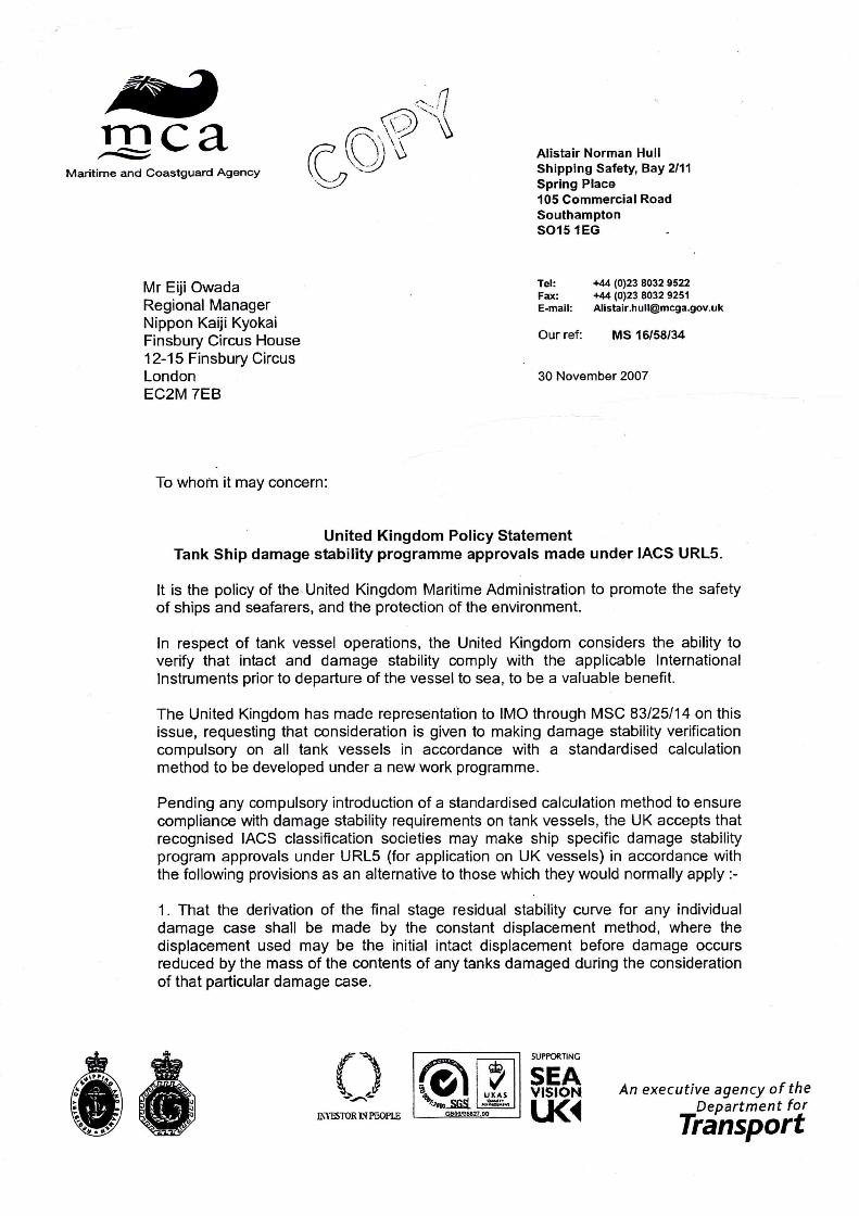
今般、英国政府より、同国籍のすべての油タンカー、ケミカルキャリアー及びガスキャリアーには損傷
時復原性要件への適合が確認できる承認された復原性計算機を搭載するよう指示がありましたので
お知らせいたします。 現在 IMO では船上における損傷時復原性適合に関する計算基準等について審議中ですが、これ
らが確定するまでは IACS Unified Requirements L5 に基づいた承認を認めるとしています。 IACS Unified Requirements L5 は 2005 年 7 月 1 日以降に建造契約が行われた新造船の復原性計
算機に適用されますが、英国籍船については既に就航している船舶を含めすべてのタンク船に適
用されることになります。 詳細につきましては、添付の英国政府指示文書を参照下さい。 なお、本件に関してご不明な点は、以下の部署にお問い合わせください。 財団法人 日本海事協会 (ClassNK) 本部 管理センター 船体部 住所: 東京都千代田区紀尾井町 4-7(郵便番号 102-8567) Tel.: 03-5226-2017 / 2018 Fax: 03-5226-2019 E-mail: [email protected]
添付:
1. 英国政府指示文書(MS 16/58/34) 2. IACS Unified Requirements L5

L5
Onboard Computers for StabilityCalculations
Preamble
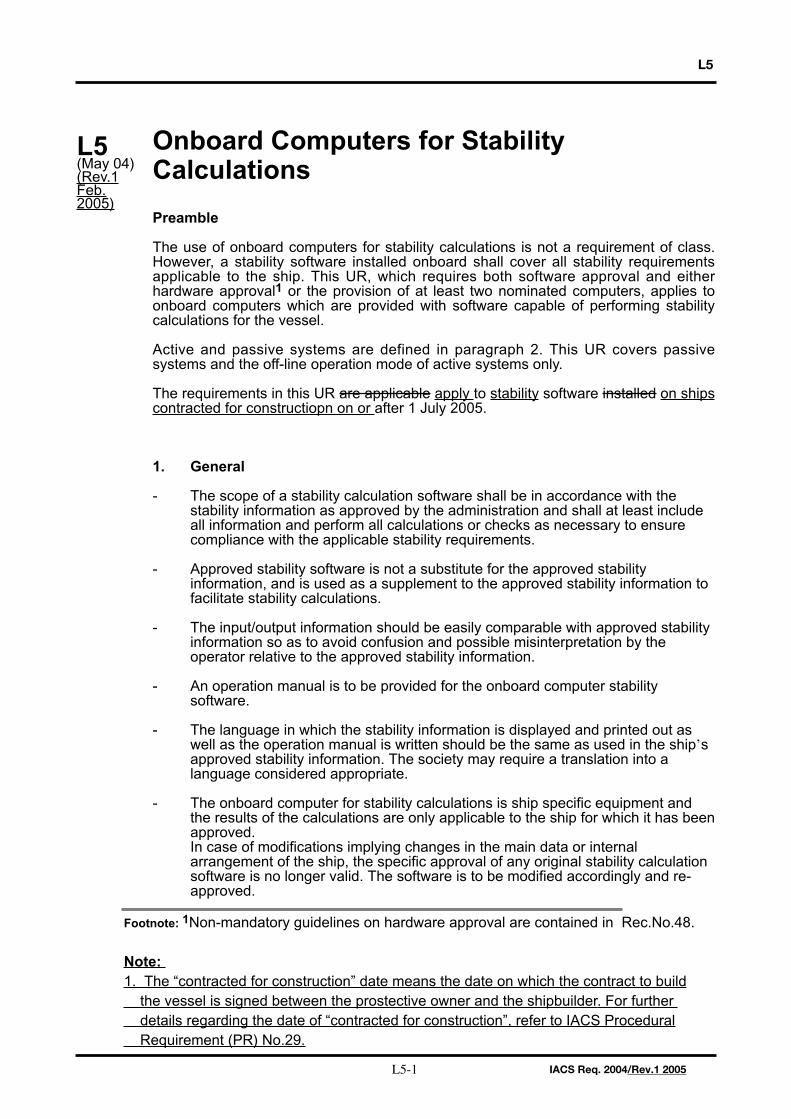
The use of onboard computers for stability calculations is not a requirement of class.However, a stability software installed onboard shall cover all stability requirementsapplicable to the ship. This UR, which requires both software approval and eitherhardware approval1 or the provision of at least two nominated computers, applies toonboard computers which are provided with software capable of performing stabilitycalculations for the vessel.
Active and passive systems are defined in paragraph 2. This UR covers passivesystems and the off-line operation mode of active systems only.
The requirements in this UR are applicable apply to stability software installed on shipscontracted for constructiopn on or after 1 July 2005.
1. General
- The scope of a stability calculation software shall be in accordance with the stability information as approved by the administration and shall at least include all information and perform all calculations or checks as necessary to ensure compliance with the applicable stability requirements.
- Approved stability software is not a substitute for the approved stability information, and is used as a supplement to the approved stability information to facilitate stability calculations.
- The input/output information should be easily comparable with approved stability information so as to avoid confusion and possible misinterpretation by the operator relative to the approved stability information.
- An operation manual is to be provided for the onboard computer stability software.
- The language in which the stability information is displayed and printed out as well as the operation manual is written should be the same as used in the ship’s approved stability information. The society may require a translation into a language considered appropriate.
- The onboard computer for stability calculations is ship specific equipment and the results of the calculations are only applicable to the ship for which it has beenapproved. In case of modifications implying changes in the main data or internal arrangement of the ship, the specific approval of any original stability calculation software is no longer valid. The software is to be modified accordingly and re-approved.
L5(May 04)(Rev.1Feb.2005)
IACS Req. 2004/Rev.1 2005L5-1
Footnote: 1Non-mandatory guidelines on hardware approval are contained in Rec.No.48.
Note: 1. The “contracted for construction” date means the date on which the contract to build the vessel is signed between the prostective owner and the shipbuilder. For further details regarding the date of “contracted for construction”, refer to IACS Procedural Requirement (PR) No.29.
L5
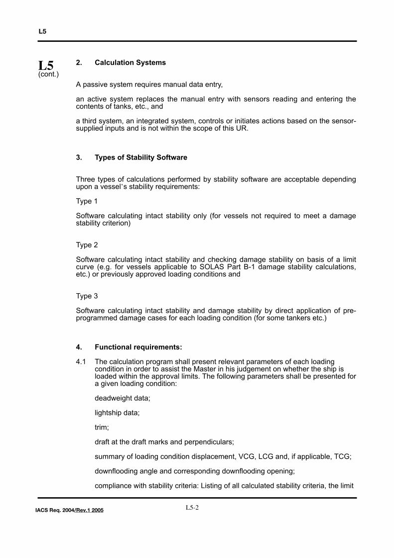
2. Calculation Systems
A passive system requires manual data entry,
an active system replaces the manual entry with sensors reading and entering thecontents of tanks, etc., and
a third system, an integrated system, controls or initiates actions based on the sensor-supplied inputs and is not within the scope of this UR.
3. Types of Stability Software
Three types of calculations performed by stability software are acceptable dependingupon a vessel’s stability requirements:
Type 1
Software calculating intact stability only (for vessels not required to meet a damagestability criterion)
Type 2
Software calculating intact stability and checking damage stability on basis of a limitcurve (e.g. for vessels applicable to SOLAS Part B-1 damage stability calculations,etc.) or previously approved loading conditions and
Type 3
Software calculating intact stability and damage stability by direct application of pre-programmed damage cases for each loading condition (for some tankers etc.)
4. Functional requirements:
4.1 The calculation program shall present relevant parameters of each loading condition in order to assist the Master in his judgement on whether the ship is loaded within the approval limits. The following parameters shall be presented fora given loading condition:
deadweight data;
lightship data;
trim;
draft at the draft marks and perpendiculars;
summary of loading condition displacement, VCG, LCG and, if applicable, TCG;
downflooding angle and corresponding downflooding opening;
compliance with stability criteria: Listing of all calculated stability criteria, the limit
L5(cont.)
L5-2IACS Req. 2004/Rev.1 2005
L5
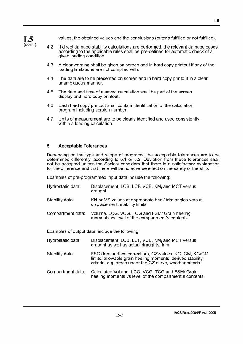
values, the obtained values and the conclusions (criteria fulfilled or not fulfilled).
4.2 If direct damage stability calculations are performed, the relevant damage cases according to the applicable rules shall be pre-defined for automatic check of a given loading condition.
4.3 A clear warning shall be given on screen and in hard copy printout if any of the loading limitations are not complied with.
4.4 The data are to be presented on screen and in hard copy printout in a clear unambiguous manner.
4.5 The date and time of a saved calculation shall be part of the screen display and hard copy printout.
4.6 Each hard copy printout shall contain identification of the calculation program including version number.
4.7 Units of measurement are to be clearly identified and used consistently within a loading calculation.
5. Acceptable Tolerances
Depending on the type and scope of programs, the acceptable tolerances are to bedetermined differently, according to 5.1 or 5.2. Deviation from these tolerances shallnot be accepted unless the Society considers that there is a satisfactory explanationfor the difference and that there will be no adverse effect on the safety of the ship.
Examples of pre-programmed input data include the following:
Hydrostatic data: Displacement, LCB, LCF, VCB, KMt and MCT versus draught.
Stability data: KN or MS values at appropriate heel/ trim angles versus displacement, stability limits.
Compartment data: Volume, LCG, VCG, TCG and FSM/ Grain heeling moments vs level of the compartment’s contents.
Examples of output data include the following:
Hydrostatic data: Displacement, LCB, LCF, VCB, KMt and MCT versus draught as well as actual draughts, trim.
Stability data: FSC (free surface correction), GZ-values, KG, GM, KG/GM limits, allowable grain heeling moments, derived stability criteria, e.g. areas under the GZ curve, weather criteria.
Compartment data: Calculated Volume, LCG, VCG, TCG and FSM/ Grain heeling moments vs level of the compartment’s contents.
L5(cont.)
L5-3IACS Req. 2004/Rev.1 2005
L5
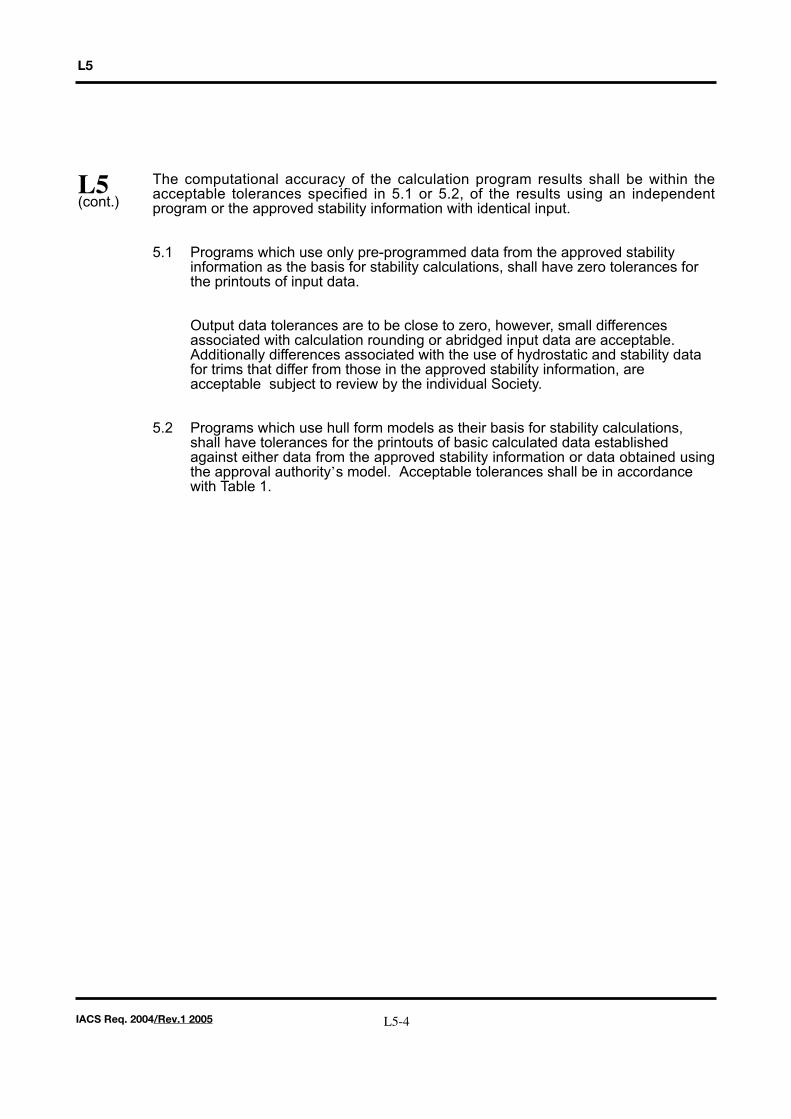
The computational accuracy of the calculation program results shall be within theacceptable tolerances specified in 5.1 or 5.2, of the results using an independentprogram or the approved stability information with identical input.
5.1 Programs which use only pre-programmed data from the approved stability information as the basis for stability calculations, shall have zero tolerances for the printouts of input data.
Output data tolerances are to be close to zero, however, small differences associated with calculation rounding or abridged input data are acceptable. Additionally differences associated with the use of hydrostatic and stability data for trims that differ from those in the approved stability information, are acceptable subject to review by the individual Society.
5.2 Programs which use hull form models as their basis for stability calculations, shall have tolerances for the printouts of basic calculated data established against either data from the approved stability information or data obtained usingthe approval authority’s model. Acceptable tolerances shall be in accordance with Table 1.
L5(cont.)
L5-4IACS Req. 2004/Rev.1 2005
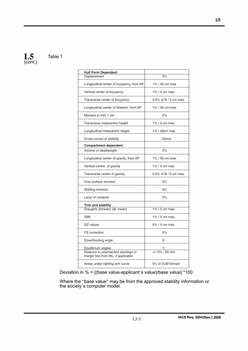
Table 1
Deviation in % = {(base value-applicant’s value)/base value} *100
Where the “base value” may be from the approved stability information or the society’s computer model.
L5
L5(cont.)
Hull Form DependentDisplacement 2%
Longitudinal center of buoyancy, from AP 1% / 50 cm max
Vertical center of bouyancy 1% / 5 cm max
Transverse center of bouyancy 0.5% of B / 5 cm max
Longitudinal center of flotation, from AP 1% / 50 cm max
Moment to trim 1 cm 2%
Transverse metacentric height 1% / 5 cm max
Longitudinal metacentric height 1% / 50cm max
Cross curves of stability 50mm
Compartment dependent
Volume or deadweight 2%
Longitudinal center of gravity, from AP 1% / 50 cm max
Vertical centre of gravity 1% / 5 cm max
Transverse center of gravity 0.5% of B / 5 cm max
Free surface moment 2%
Shifting moment 5%
Level of contents 2%
Trim and stabilityDraughts (forward, aft, mean) 1% / 5 cm max
GMt 1% / 5 cm max
GZ values 5% / 5 cm max
FS correction 2%
Downflooding angle 2O
Equilibrium angles 1O
Distance to unprotected openings or +/- 5% / 50 mmmargin line from WL, if applicable
Areas under righting arm curve 5% or 0,0012mrad
L5-5 IACS Req. 2004/Rev.1 2005
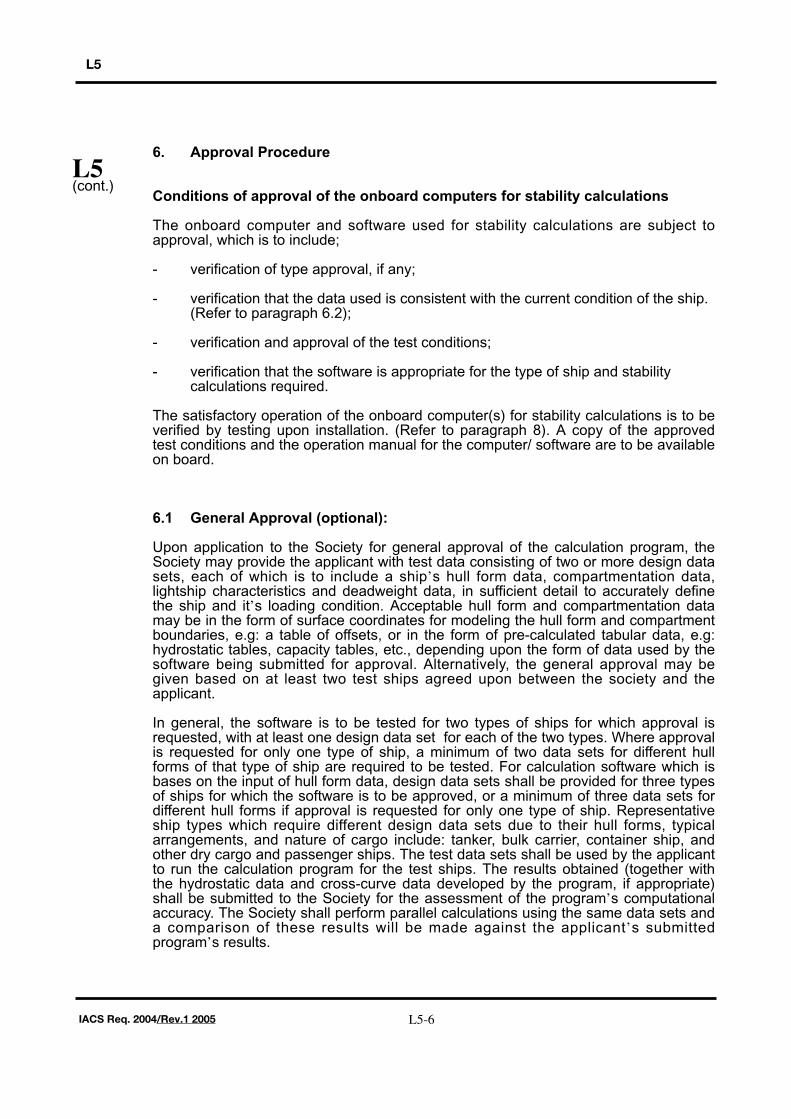
6. Approval Procedure
Conditions of approval of the onboard computers for stability calculations
The onboard computer and software used for stability calculations are subject toapproval, which is to include;
- verification of type approval, if any;
- verification that the data used is consistent with the current condition of the ship. (Refer to paragraph 6.2);
- verification and approval of the test conditions;
- verification that the software is appropriate for the type of ship and stability calculations required.
The satisfactory operation of the onboard computer(s) for stability calculations is to beverified by testing upon installation. (Refer to paragraph 8). A copy of the approvedtest conditions and the operation manual for the computer/ software are to be availableon board.
6.1 General Approval (optional):
Upon application to the Society for general approval of the calculation program, theSociety may provide the applicant with test data consisting of two or more design datasets, each of which is to include a ship’s hull form data, compartmentation data,lightship characteristics and deadweight data, in sufficient detail to accurately definethe ship and it’s loading condition. Acceptable hull form and compartmentation datamay be in the form of surface coordinates for modeling the hull form and compartmentboundaries, e.g: a table of offsets, or in the form of pre-calculated tabular data, e.g:hydrostatic tables, capacity tables, etc., depending upon the form of data used by thesoftware being submitted for approval. Alternatively, the general approval may begiven based on at least two test ships agreed upon between the society and theapplicant.
In general, the software is to be tested for two types of ships for which approval isrequested, with at least one design data set for each of the two types. Where approvalis requested for only one type of ship, a minimum of two data sets for different hullforms of that type of ship are required to be tested. For calculation software which isbases on the input of hull form data, design data sets shall be provided for three typesof ships for which the software is to be approved, or a minimum of three data sets fordifferent hull forms if approval is requested for only one type of ship. Representativeship types which require different design data sets due to their hull forms, typicalarrangements, and nature of cargo include: tanker, bulk carrier, container ship, andother dry cargo and passenger ships. The test data sets shall be used by the applicantto run the calculation program for the test ships. The results obtained (together withthe hydrostatic data and cross-curve data developed by the program, if appropriate)shall be submitted to the Society for the assessment of the program’s computationalaccuracy. The Society shall perform parallel calculations using the same data sets anda comparison of these results will be made against the applicant’s submittedprogram’s results.
L5
L5(cont.)
L5-6IACS Req. 2004/Rev.1 2005
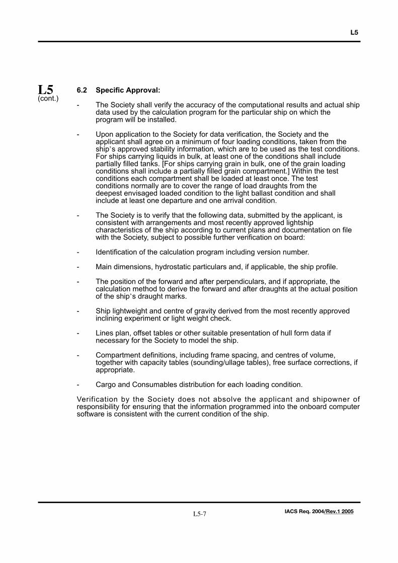
6.2 Specific Approval:
- The Society shall verify the accuracy of the computational results and actual shipdata used by the calculation program for the particular ship on which the program will be installed.
- Upon application to the Society for data verification, the Society and the applicant shall agree on a minimum of four loading conditions, taken from the ship’s approved stability information, which are to be used as the test conditions.For ships carrying liquids in bulk, at least one of the conditions shall include partially filled tanks. [For ships carrying grain in bulk, one of the grain loading conditions shall include a partially filled grain compartment.] Within the test conditions each compartment shall be loaded at least once. The test conditions normally are to cover the range of load draughts from the deepest envisaged loaded condition to the light ballast condition and shall include at least one departure and one arrival condition.
- The Society is to verify that the following data, submitted by the applicant, is consistent with arrangements and most recently approved lightship characteristics of the ship according to current plans and documentation on file with the Society, subject to possible further verification on board:
- Identification of the calculation program including version number.
- Main dimensions, hydrostatic particulars and, if applicable, the ship profile.
- The position of the forward and after perpendiculars, and if appropriate, the calculation method to derive the forward and after draughts at the actual position of the ship’s draught marks.
- Ship lightweight and centre of gravity derived from the most recently approved inclining experiment or light weight check.
- Lines plan, offset tables or other suitable presentation of hull form data if necessary for the Society to model the ship.
- Compartment definitions, including frame spacing, and centres of volume, together with capacity tables (sounding/ullage tables), free surface corrections, if appropriate.
- Cargo and Consumables distribution for each loading condition.
Verification by the Society does not absolve the applicant and shipowner ofresponsibility for ensuring that the information programmed into the onboard computersoftware is consistent with the current condition of the ship.
L5
L5(cont.)
L5-7 IACS Req. 2004/Rev.1 2005
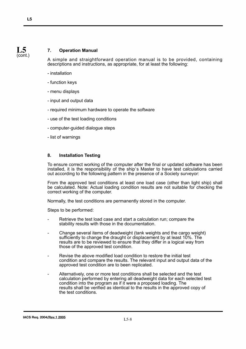
7. Operation Manual
A simple and straightforward operation manual is to be provided, containingdescriptions and instructions, as appropriate, for at least the following:
- installation
- function keys
- menu displays
- input and output data
- required minimum hardware to operate the software
- use of the test loading conditions
- computer-guided dialogue steps
- list of warnings
8. Installation Testing
To ensure correct working of the computer after the final or updated software has beeninstalled, it is the responsibility of the ship’s Master to have test calculations carriedout according to the following pattern in the presence of a Society surveyor:
From the approved test conditions at least one load case (other than light ship) shallbe calculated. Note: Actual loading condition results are not suitable for checking thecorrect working of the computer.
Normally, the test conditions are permanently stored in the computer.
Steps to be performed:
- Retrieve the test load case and start a calculation run; compare the stability results with those in the documentation.
- Change several items of deadweight (tank weights and the cargo weight) sufficiently to change the draught or displacement by at least 10%. The results are to be reviewed to ensure that they differ in a logical way from those of the approved test condition.
- Revise the above modified load condition to restore the initial test condition and compare the results. The relevant input and output data of the approved test condition are to been replicated.
- Alternatively, one or more test conditions shall be selected and the test calculation performed by entering all deadweight data for each selected test condition into the program as if it were a proposed loading. The results shall be verified as identical to the results in the approved copy of the test conditions.
L5
L5(cont.)
L5-8IACS Req. 2004/Rev.1 2005
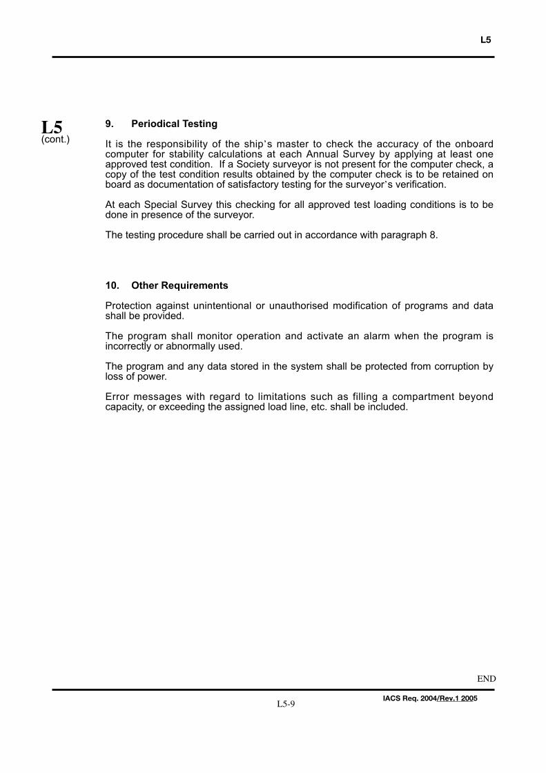
9. Periodical Testing
It is the responsibility of the ship’s master to check the accuracy of the onboardcomputer for stability calculations at each Annual Survey by applying at least oneapproved test condition. If a Society surveyor is not present for the computer check, acopy of the test condition results obtained by the computer check is to be retained onboard as documentation of satisfactory testing for the surveyor’s verification.
At each Special Survey this checking for all approved test loading conditions is to bedone in presence of the surveyor.
The testing procedure shall be carried out in accordance with paragraph 8.
10. Other Requirements
Protection against unintentional or unauthorised modification of programs and datashall be provided.
The program shall monitor operation and activate an alarm when the program isincorrectly or abnormally used.
The program and any data stored in the system shall be protected from corruption byloss of power.
Error messages with regard to limitations such as filling a compartment beyondcapacity, or exceeding the assigned load line, etc. shall be included.
L5
L5(cont.)
L5-9IACS Req. 2004/Rev.1 2005
END