clarifiers - newea · clarifiers: making what you have ….. work better! by: john esler, p.e.,...
TRANSCRIPT

Clarifiers: Making What You Have ….. Work Better!
By: John Esler, P.E., President
Clarifiers, Inc. Enfield, NH

Clarifier Configurations …..
l Basic Rectangular l Gould Type II Rectangular l Basic Circular (CFPO) l Peripheral Feed (PF/PO) l Peripheral Feed (Spiral Flow) l Square

Always Think in Terms of the…..
l Flow Pattern !!!! l Influent Structure l Effluent Configuration l Sludge Collection

Basic Rectangular ….
1. Balance Flows!! 2. Think BAFFLES! 3. Modify the launders 4. Modify the Influent Structure


Typical Flow Patternin a Rectangular Clarifier:
Q + R Q
R

Single Mid-Tank Baffle
Multiple Baffles


Fairbanks (AK)


Golden Heart Test Baffle Loca2ons
100’
20’
30’ 60’
15’ 13’
O O 14’ Idler
Sprocket
7’ +/- Drive
Sprocket
34’ 34’
Figure 3
15’ 13’
O O
26’ 26’ 26’
#6
#5
#4 New
Influent Nozzles only
New flow measurement
flume (typical)
Block rear weirs
(typical)

New Opposing Jet Inlets

l New Intermediate Baffles

0
50
100
150
200
250
300
350
0 50 100 150 200 250
Dye Co
ncen
tra-
on
Time (minutes)
Clarifier Dye Curve Comparison at 1.3 mgd Flow Rate SOR = 650 gal/sq H/day
Clarifier 3 Clarifier 4 Clarifier 5 Clarifier 6 Clarifier 7
B1
Theore2cal D.T. = 245 minutes Opera2ng D.T. : Clar #3 = 44 minutes (Control) Clar #4 = 71 minutes Clar #5 = 125 minutes Clar #6 = 104 minutes Clar #7 = 37 minutes (Control)
#5

Typical Flow Pattern in a Gould Type II Clarifier:
Q + R
R
Q
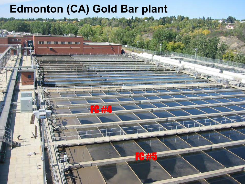
FC #4
FC #5
Edmonton (CA) Gold Bar plant

13’ SWD
Typical Cross-Section Clarifiers #1 thru #5
13’ SWD 13.5’
Depth @ hopper
11’ typ spacing
85’ 165’ 56’ 120’
2’6”
sidewalk roadway
Baffles in Clarifier #4
only


Clarifier 1 - 5 Detention Time Comparisonat Normal Flow
0
50
100
150
200
250
300
350
0 50 100 150 200 250
Time (Minutes)
Dye
Rea
din
g
Clarifier 1 Clarifier 2 Clarifier 3 Clarifier 4 Clarifier 5
Clarifier Actual D.T. Theo D.T. #1 122 min 254 min #2 123 min 259 min #3 134 min 257 min #4 ** 164 min 271 min #5 127 min 271 min
2
3
1
4
7
5

1 2 3
120’ +/-
33’ +/- 33’ +/- 33’ +/- 20’ +/-
Face of Influent Baffle
20” Typ
NYC-Wards Is. Recommended Baffle Locations


Basic Circular Clarifier:
l Balance Flows! l Modify Launders l Modify Inlet l Add Baffles? l Improve Sludge Collection?

29

30

31
Typical Flow Pattern
in a Circular A.S. Clarifier:
Q + R

32

33 Modify Inlet:
LA – Hyperion plant

34
We added a new EDI with
“opposing jet” nozzles to
Clarifier 3A …..
And gained at least 10 mgd MORE
capacity per clarifier!!

NYC-DEP Jamaica WWTP

Brockton, MA

37
The first Crosby (Stamford)
peripheral baffle
The late Bob Crosby

38
8-sided Crosby Cylindrical Baffle
AKA the Kessler-Esler Baffle
(Franklin, NH; New Haven, CT; Atlanta, GA; Jamaica, NYC)

Upper Blackstone


Norwalk, CT

43
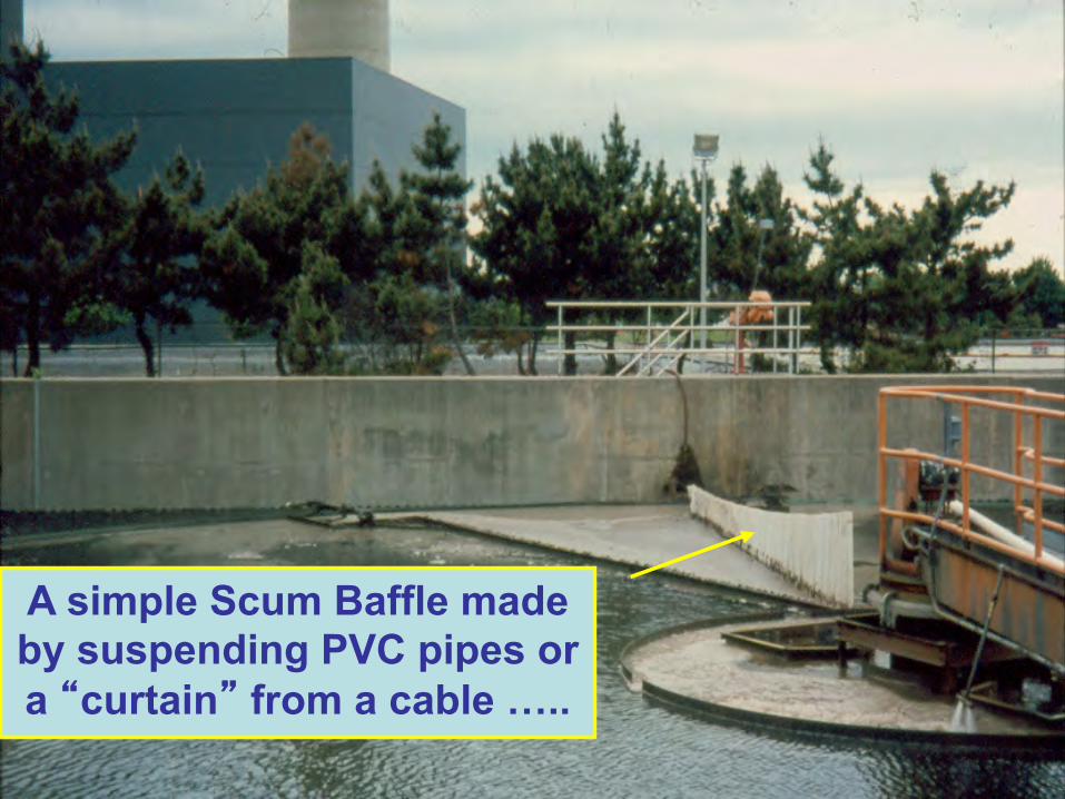
A simple Scum Baffle made by suspending PVC pipes or a “curtain” from a cable …..

44
Scum flusher

Clarifiers: Making What You Have ….. Work WORSE !!!
Just a few examples …..

The wrong baffles …….

McKinney Baffle
Crosby Baffle
Too much of a good thing!!


Miami-Dade South District


Too many weirs!!

Submerged Centerwells?


Chicopee, MA


Champhered Corner!

There’s more to life than clarifiers!

62
WWW.CLARIFIERS.COM