clapets anti-retour check valves rÜckschlagventile · c2 - clapet anti-retour réglable -...
TRANSCRIPT

CLAPETS ANTI-RETOURCHECK VALVES
RÜCKSCHLAGVENTILE
sag
an
a-c
he
ck-
valv
e-0
5-5
����������������
���� �����

2sagana-check-valve-05-5
Droits de modifications réservés All rights of changes reserved Änderungsrechte vorbehalten
����������������
���� �����
Description - Description - Beschreibung
Spécifications - Specifications - Spezifikationen
Différences visuelles - Visual differences - Unterscheidungsmerkmale
Connexions disponibles - Available connections - Verfügbare Anschlüsse
C1 - Clapet anti-retour - Check valve - Rückschlagventil
C2 - Clapet anti-retour réglable - Adjustable check valve - Regulierbares Rückschlagventil
C3 - Clapet anti-retour - Check valve - Rückschlagventil
C4 - Clapet anti-retour réglable - Adjustable check valve - Regulierbares Rückschlagventil
AT300 - Clapet anti-retour - Check valve - Rückschlagventil
PG - Purge manuelle - Manual Purge - Entlüftungsventil
Données techniques - Technical data - Technische Daten 27
24
20
17
12
10
8
4
5
6
7

3sagana-check-valve-05-5
Droits de modifications réservés All rights of changes reserved Änderungsrechte vorbehalten
����������������
���� �����
SOMMAIRE SUMMARY INHALTSVERZEICHNIS
SS 316L & BrassWorking pressure up to 200 bar.One size body (compact)Craking pressure up to 50 psi.NPT connections only.
Brass & SS 316LWorking pressure up to 200 bar.One size body (compact)Adjustable cracking pressure up to 350 psiNPT connections only
Brass & SS 316LWorking pressure up to 300 bar.Maximale differential pressure: 200 bar.Cracking pressure up to 100 psi.Large choice of end connections.
Acier inoxydable 316L et laitonPression de service max: 200 bar.Corps une pièce (compacte)Pression d’ouverture jusqu’à 50 psiSeulement avec raccord NPT.
Acier inoxydable 316L et laitonPression de service max: 200 bar.Corps une pièce (compacte)Pression d’ouverture réglable jusqu’à 350 psi.Seulement avec raccord NPT.
Acier inoxydable 316L et laitonPression de service max: 300 bar.Pression différentielle max: 200 bar.Pression d’ouverture jusqu’à 100 psi.Large choix de raccords.
Acier inoxydable 316L et laitonPression de service max: 300 bar.Pression différentielle max: 200 bar.Pression d’ouverture réglable jusqu’à 350 psi.Large choix de raccords.
Acier inoxydable 316LPression de service max: 300 bar.Pression différentielle max: 300 bar.Pression d’ouverture jusqu’à 100 psi.Large choix de raccords.
Brass & SS 316LWorking pressure up to 300 bar.Maximale differential pressure: 200 bar.Adjustable cracking pressure up to 350 psi.Large choice of end connections.
SS 316LWorking pressure up to 300 bar.Maximale differential pressure: 300 bar.Cracking pressure up to 100 psi.Large choice of end connections.
C1
C2
C3
C4
AT300
Edelstahl 316L und MessingMax. Betriebsdruck 200 BarKörper aus einem Stück gefertigt (kompakt)Öffnungsdruck bis 50 psiNur mit NPT-Verbindungselement
Edelstahl 316L und MessingMax. Betriebsdruck 200 BarKörper aus einem Stück gefertigt (kompakt)Öffnungsdruck bis 350 psi einstellbarNur mit NPT-Verbindungselement
Edelstahl 316L und MessingMax. Betriebsdruck 300 BarMax. Differenzdruck 200 BarÖffnungsdruck bis 100 psiGroße Auswahl an Verbindungselementen
Edelstahl 316L und MessingMax. Betriebsdruck 300 BarMax. Differenzdruck 200 BarÖffnungsdruck bis 350 psi einstellbarGroße Auswahl an Verbindungselementen
Edelstahl 316LMax. Betriebsdruck 300 BarMax. Differenzdruck 300 BarÖffnungsdruck bis 100 psiGroße Auswahl an Verbindungselementen
8
10
12
17
20

4sagana-check-valve-05-5
Droits de modifications réservés All rights of changes reserved Änderungsrechte vorbehalten
����������������
���� �����
Applications
Les clapets anti-retour SAGANA®
permettent un contrôle uni-directionnel des liquides et des gaz.Ils sont utilisés dans des domainesvariés tels que l’industrie, lapétrochimie, l’instrumentation, larecherche.
Caractéristiques
Les clapets anti-retour SAGANA® sontdisponibles avec différents tarrages deressorts:Ressort fixe tarré pour une pressionchoisie.Ressort à tarrage réglable.
Matériaux
Corps, clapet, écrou et bague eninox ou laiton (autres matières surdemande).Joints toriques en VITON® (FPM) enstandard (autres matières surdemande).Ressort en acier inoxydable 302.Joints toriques: FPM, NBR, EPDM, (PTFE)
Essais
Tous les clapets anti-retour sont testésà 100%.
Applications
SAGANA® check valves allowunidirectional control of liquids andgases.They are used in varied fields such asindustry, petrochemicals,instrumentation and research.
Characteristics
SAGANA® check valves are availablewith different springs settings:Fixed spring setting for a selectedpressure.Adjustable spring setting.
Materials
Body, valve, nut and ferrules in stainlesssteel or brass (other materials onrequest).O-rings in VITON® (FPM) as standard(other materials on request).Springs in Stainless Steel 302.O-rings: FPM, NBR, EPDM, (PTFE)
Tests
All check valves are 100% leak tested .
Einsatzbereiche
Die SAGANA® Rückschlagventileermöglichen eine unidirektionelleSteuerung von Flüssigkeiten undGasen.Sie werden aus Sicherheitsgründenin vielfältigsten Bereichen eingesetzt,z.B. in der Industrie, der Petrochemie,der Instrumentierung und derForschung.
Eigenschaften
Die SAGANA® Rückschlagventile sind mitverschiedenen Federstärken lieferbar:Feste Feder, auf einen bestimmtenDruck eingestellt.Feder mit regulierbarer Stärke.
Werkstoffe
Ventilkörper, Mutter und Ring ausEdelstahl oder Messing (andereWerkstoffe auf Anfrage)O-Ring-Dichtungen serienmäßig ausVITON® (FPM) (andere Werkstoffeauf Anfrage)Feder aus Edelstahl 302.O-Ring-Dichtungen: FPM, NBR, EPDM,(PTFE)
Test
Sämtliche Ventile werden zu 100%getestet.
ATTENTION
Respecter le sens d’écoulement dugaz indiqué par la flèche sur le corpsdu clapet.Raccorder la tuyauterie amont etaval en veillant bien à la propretédes raccords.Respecter les pressions maximalesde service (PN).Ne pas dévisser les raccords souspression.
Viton®: marque déposée de Dupont
CAUTION
Comply with the gas flow directionindicated by the arrow on thevalve body.Connect the upstream anddownstream pipes taking care toensure the cleanliness of theconnectors.Comply with the maximum servicepressures (PN)Do not loosen the connectorsunder pressure.
Viton®: is a Trade Mark of Dupont
VORSICHT
Beachten Sie die Durchfluss-richtung des Gases, die durch denPfeil auf dem Ventilkörpergekennzeichnet wird.Schließen Sie die Rohre oberhalbund unterhalb des Ventils an, undachten Sie dabei sorgfältig auf dieSauberkeit der Verbindungen.
Viton®: Trade Mark von Dupont
DESCRIPTION DESCRIPTION BESCHREIBUNG
5sagana-check-valve-05-5
Droits de modifications réservés All rights of changes reserved Änderungsrechte vorbehalten
����������������
���� �����
SPECIFICATIONS SPECIFICATIONS SPEZIFIKATIONEN
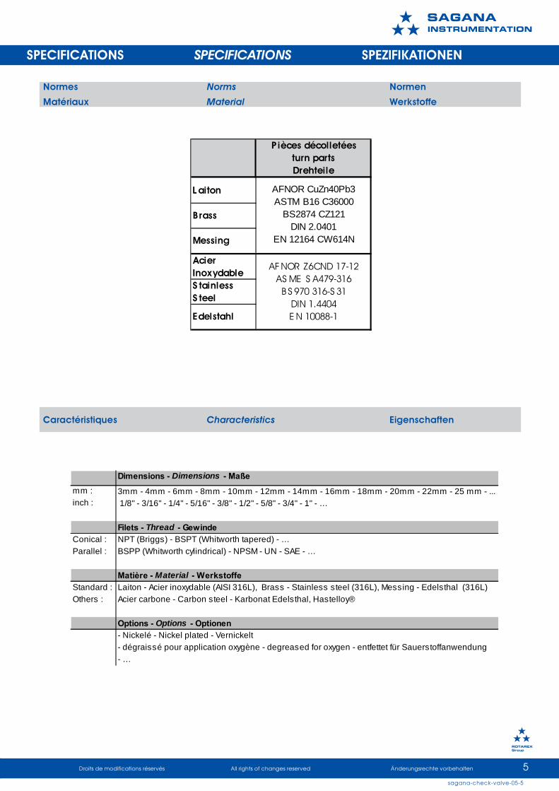
Normes Norms Normen
Matériaux Material Werkstoffe
Pièces décolletéesturn partsDrehteile
L aiton
Acier InoxydableS tainlessS teel
Edelstahl
Messing
Brass
AFNOR CuZn40Pb3 ASTM B16 C36000
BS2874 CZ121 DIN 2.0401
EN 12164 CW614N
AFNOR Z6CND 17-12 AS ME S A479-316
BS 970 316-S 31 DIN 1.4404 EN 10088-1
Caractéristiques Characteristics Eigenschaften
mm : 3mm - 4mm - 6mm - 8mm - 10mm - 12mm - 14mm - 16mm - 18mm - 20mm - 22mm - 25 mm - ... inch : 1/8" - 3/16" - 1/4" - 5/16" - 3/8" - 1/2" - 5/8" - 3/4" - 1" - …
Filets - Thread - GewindeConical : NPT (Briggs) - BSPT (Whitworth tapered) - …Parallel : BSPP (Whitworth cylindrical) - NPSM - UN - SAE - …
Matière - Material - WerkstoffeStandard : Laiton - Acier inoxydable (AISI 316L), Brass - Stainless steel (316L), Messing - Edelsthal (316L)Others : Acier carbone - Carbon steel - Karbonat Edelsthal, Hastelloy®
Options - Options - Optionen- Nickelé - Nickel plated - Vernickelt- dégraissé pour application oxygène - degreased for oxygen - entfettet für Sauerstoffanwendung- …
Dimensions - Dimensions - Maße

6sagana-check-valve-05-5
Droits de modifications réservés All rights of changes reserved Änderungsrechte vorbehalten
����������������
���� �����
Différences visuelles entre Visual differences Optische Unterscheidungfiletage NPT / BSPT between NPT / BSPT zwischen NPT / BSPT
Les clapets anti-retour avecfiletage BSPT (mâle ou femelle)sont livrés avec épaulements
DIFFÉRENCES VISUELLES VISUAL DIFFERENCES UNTERSCHEIDUNGSMERKMALE
Différences visuelles Visual differences Unterscheidungsmerkmaleentre métrique / fractionnel between metric / inch zwischen Metrisch / Zoll
Les clapets anti-retour avecraccords à double bague pourtubes métriques sont livrés avecépaulements.
Check-valves manufactured with tubefittings for metric tubes are providedwith shoulders.
Rückschlagventil für metrischeAbmessungen sind mit Bundgefertigt.
Check-valves manufactured withBSPT thread are provided withshoulders
Rüchschlagventil für BSPT Gewinde sindmit Bund gefertigt

7sagana-check-valve-05-5
Droits de modifications réservés All rights of changes reserved Änderungsrechte vorbehalten
����������������
���� �����
CONNEXIONS DISPONIBLES AVAILABLE CONNECTIONS VERFÜGBARE ANSCHLÜSSE
Dim. 1/8" 1/4" 3/8" 1/2" 3/4" 1"Ref. 2M 4M 6M 8M 12M 16M
Male NPT
Dim. 1/8" 1/4" 3/8" 1/2" 3/4" 1"Ref. 2F 4F 6F 8F 12F 16F
Femelle NPT
Dim. 1/8" 1/4" 3/8" 1/2" 3/4" 1"Ref . 2FT 4FT 6FT 8FT 12FT 16FT
Female BSPT
Dim. 1/4" 3/4" 1"Ref. 4V 12V 16V
Male Gazel® (Face seal )3/8" or 1/2"
8V
Dim. 1/4" 3/4" 1"Ref. 4FV 12FV 16FV
Female Gazel® ( Face seal )3/8" or 1/2"
8FV
Dim. 1/8" 1/4" 3/8" 1/2" 3/4" 1"Ref. 2FP 4FP 6FP 8FP 12FP 16FP
Femelle BSPP
Dim. 1/8" 1/4" 3/8" 1/2" 3/4" 1"Ref. 2MT 4MT 6MT 8MT 12MT 16MT
Male BSPT
Dim. 1/8" 1/4" 3/8" 1/2" 3/4" 1"Ref. 2A 4A 6A 8A 12A 16A
Sagana® Tube adapter
Dim. 1/8" 1/4" 3/8" 1/2" 3/4" 1"Ref. 2S 4S 6S 8S 12S 16S
Sagana® Tube fittings
Dim. 3mm 6mm 8mm 10mm 12mm 20mm 22mm 25mmRef. M3S M6S M8S M10S M12S M20S M22S M25S
Sagana® Tube fittings
Dim. 1/8" 1/4" 3/8" 1/2" 3/4" 1"Ref. 2MP 4MP 6MP 8MP 12MP 16MP
Male BSPP (RS)

8sagana-check-valve-05-5
Droits de modifications réservés All rights of changes reserved Änderungsrechte vorbehalten
����������������
���� �����
CLAPET ANTI-RETOUR CHECK VALVE RÜCKSCHLAGVENTIL
SERIES C1 - ONE PIECE -
DESCRIPTION
Les clapets anti-retour série «C1» ontun encombrement limité grâce à uncorps usiné en une seule pièce.Le clapet «C1» est disponibleseulement avec des raccords NPT.La pression maximale d’utilisation estde 200 bar.Différentes pressions d’ouverturesont disponibles.
INFORMATIONS TECHNIQUES
NOMENCLATURE
DESCRIPTION
Series «C1» check valves have smallvolumes with use of a one piecemachined body.Check valve «C1» is available onlywith NPT connectors.The maximum operating pressure is200 bar.Different cracking pressures areavailable.
TECHNICAL DATA
BESCHREIBUNGDie Rückschlagventile der Baureihe«C1» weisen dank ihres aus einemStück gearbeiteten Korpus einengeringen Raumbedarf auf.Das Ventil «C1» ist ausschließlich mitNPT-Verbindungen lieferbar.Der maximale Einsatzdruck beträgt200 bar.Es sind verschiedeneÖffnungsdrücke lieferbar.
TECHNISCHE DATEN
PART LIST NOMENKLATUR
Acier Inoxydable Stainless steel
Edelstahl
Laiton Brass
MessingPression de service max.
Maximum working pressure Max Betriebsdruck
Pression inverse max. Maximum back pressure
Max. GegendruckTempérature de service
Temperature range BetriebstemperaturenPression d'ouverture
Cracking pressure (psi)öffnungsdruck
200 bar (2900 psi)
200 bar ( 2900 psi )
Voir le tableau "matière du joint" See the "Seal material" table
Siehe die Tabelle"O-Ringwerkstoff"1/3, 1, 3,5, 10, 25,
40, 50
Matière du joint Température de serviceSeal Material Temperature rating
0-Ringwerkstoff BetriebstemperaturenFPM -25°C to 200°C
(fluorocarbon Rubber) -13°F to 392°FNBR -30°C to 120°CNitrile -22°F to 248°FEPDM -50°C to 135°C
(ethylene Propylene Rubber) -58°F to 275°F
Ref.
FPM
NBR
EPDM
1 Siège Seat Sitz AISI 316L Brass2 Joint torique O-ring O-ring See table /3 Joint torique clapet Poppet O-ring O-ring Klappe See table /4 Clapet Poppet Klappe AISI 316L Brass5 Ressort Spring Feder 302 3026 Corps Body Gehäuse AISI 316L Brass
W erkstoffItem Désignation Designation Beschre ibung Materia l
Matière

9sagana-check-valve-05-5
Droits de modifications réservés All rights of changes reserved Änderungsrechte vorbehalten
����������������
���� �����
CONNEXIONS DISPONIBLES AVAILABLE CONNECTIONS VERFÜGBARE ANSCHLÜSSE
DIMENSIONS DIMENSIONS ABMESSUNGEN
COMMENTCOMMANDER
HOW TO ORDER ZUM BESTELLEN
Example:
4F4M - C1 - 1 - SS - EPDM
SERIES C1 - ONE PIECE -
1 2 3 4 5 6
Inlet connections Outlet connections Serie Cracking pressure Material O-ring Material
4M 4M-4F 1/3, 1, 3 SS FPM*4F C1 5, 10, 25 (Stainless steel) NBR8M 8M-8F 40, 50 B EPDM8F (Brass) PTFE
* FPM is the standard, you don't have to specify it
Inlet Out let mm inch mm inch
4M -C 1-* 1/4" M ale NPT 1/4" M ale NPT 41 1.61 14 0.55
4F -C 1-* 1/4" Female NPT 1/4" Female NPT 47 1.85 19 0.75
4M 4F -C 1-* 1/4" M ale NPT 1/4" Female NPT 44 1.73 19 0.75
4F 4M -C 1-* 1/4" Female NPT 1/4" M ale NPT 44 1.73 19 0.75
8M -C 1-* 1/2" M ale NPT 1/2" M ale NPT 65 2.56 22 0.87
8F -C 1-* 1/2" Female NPT 1/2" Female NPT 75 2.95 27 1.06
8M 8F -C 1-* 1/2" M ale NPT 1/2" Female NPT 70 2.76 27 1.06
8F 8M -C 1-* 1/2" Female NPT 1/2" M ale NPT 70 2.76 27 1.06
P art N umber Inlet - Out le t A H

10sagana-check-valve-05-5
Droits de modifications réservés All rights of changes reserved Änderungsrechte vorbehalten
����������������
���� �����
Acier Inoxydable Stainless steel
Edelstahl
Laiton Brass
MessingPression de service max.
Maximum working pressure Max Betriebsdruck
Pression inverse max. Maximum back pressure
Max. GegendruckTempérature de service
Temperature range BetriebstemperaturenPression d'ouverture
Cracking pressure (psi)öffnungsdruck
50 to 150 psi150 to 350 psi
200 bar (2900 psi)
200 bar ( 2900 psi )
Voir le tableau "matière du joint" See the "Seal material" table
Siehe die Tabelle"O-Ringwerkstoff"3 to 50 psi
SERIES C2 - ONE PIECE - ADJUSTABLE
DESCRIPTION
Les clapets anti-retour série «C2» ont unencombrement limité grâce à uncorps usiné en une seule pièce.Le clapet «C2» est disponibleseulement avec des raccords NPT.La pression maximale d’utilisationest de 200 bar.Différentes pressions d’ouverturesont disponibles par réglagemanuel.
INFORMATIONS TECHNIQUES
NOMENCLATURE
DESCRIPTION
Series «C2» check valves have smallvolumes by virtue of a one piecemachined body.Valve C2 is available only with NPTconnectors.The maximum operating pressure is200 bar.Different cracking pressures areavailable by manual adjustment.
TECHNICAL DATA
BESCHREIBUNG
Die Rückschlagventile der Baureihe„C2" weisen dank ihres aus einemStück gearbeiteten Korpus einengeringen Raumbedarf auf.Das Ventil C2 ist ausschließlich mitNPT-Verbindungen lieferbar.Der maximale Einsatzdruck beträgt200 bar.Durch manuelle Regulierungkönnen verschiedeneÖffnungsdrücke erzielt werden.
TECHNISCHE DATEN
PART LIST NOMENKLATUR
CLAPET ANTI-RETOUR REGLABLE ADJUSTABLE CHECK VALVE REGULIERBARES RÜCKSCHLAGVENTIL
Matière du joint Température de serviceSeal Material Temperature rating
0-Ringwerkstoff BetriebstemperaturenFPM -25°C to 200°C
(fluorocarbon Rubber) -13°F to 392°FNBR -30°C to 120°CNitrile -22°F to 248°FEPDM -50°C to 135°C
(ethylene Propylene Rubber) -58°F to 275°F
Ref.
FPM
NBR
EPDM
1 S iège S eat S itz A IS I 316L B ras s2 Joint torique O -ring O -ring S ee tab le /3 Joint torique c lapet P oppet O -ring O -ring K lappe S ee tab le /4 Clapet P oppet K lappe A IS I 316L B ras s5 Res s ort S pring F eder 302 3026 Corps B ody G ehäus e A IS I 316L B ras s7 E c rou de rég lage A djus t ing s c rew Reguliers c hrauber A IS I 316L B ras s8 Contre-éc rou Loc k ing s c rew K onterm utter A IS I 316L B ras s
W e rksto ffI te m Dé sig n a tio n De sign a tio n Be sch re ib un g M a te ria l
M a tiè re

11sagana-check-valve-05-5
Droits de modifications réservés All rights of changes reserved Änderungsrechte vorbehalten
����������������
���� �����
CONNEXIONS DISPONIBLES AVAILABLE CONNECTIONS VERFÜGBARE ANSCHLÜSSE
DIMENSIONS DIMENSIONS ABMESSUNGEN
COMMENTCOMMANDER
HOW TO ORDER ZUM BESTELLEN
Example:
4M4F - C2 - 50 - SS - EPDM
SERIES C2 - ONE PIECE - ADJUSTABLE
1 2 3 4 5 6
Inlet connections Outlet connections Serie Cracking pressure Material O-ring Material
4M 4M 3 (3 to 50) SS FPM*4F 4F C2 50 (50 to 150) (Stainless steel) NBR8M 8M 150 (150 to 350) B EPDM8F 8F (Brass) PTFE
* FPM is the standard, you don't have to specify it
Inlet Outlet mm inch mm inch
4M -C 2-* 1/4" M ale NPT 1/4" M ale NPT 41 1.61 14 0.55
4F -C 2-* 1/4" Female NPT 1/4" Female NPT 47 1.85 19 0.75
4M 4F -C 2-* 1/4" M ale NPT 1/4" Female NPT 44 1.73 19 0.75
4F 4M -C 2-* 1/4" Female NPT 1/4" M ale NPT 44 1.73 19 0.75
8M -C 2-* 1/2" M ale NPT 1/2" M ale NPT 65 2.56 22 0.87
8F -C 2-* 1/2" Female NPT 1/2" Female NPT 75 2.95 27 1.06
8M 8F -C 2-* 1/2" M ale NPT 1/2" Female NPT 70 2.76 27 1.06
8F 8M -C 2-* 1/2" Female NPT 1/2" M ale NPT 70 2.76 27 1.06
P art N umber Inlet - Out le t A H

12sagana-check-valve-05-5
Droits de modifications réservés All rights of changes reserved Änderungsrechte vorbehalten
����������������
���� �����
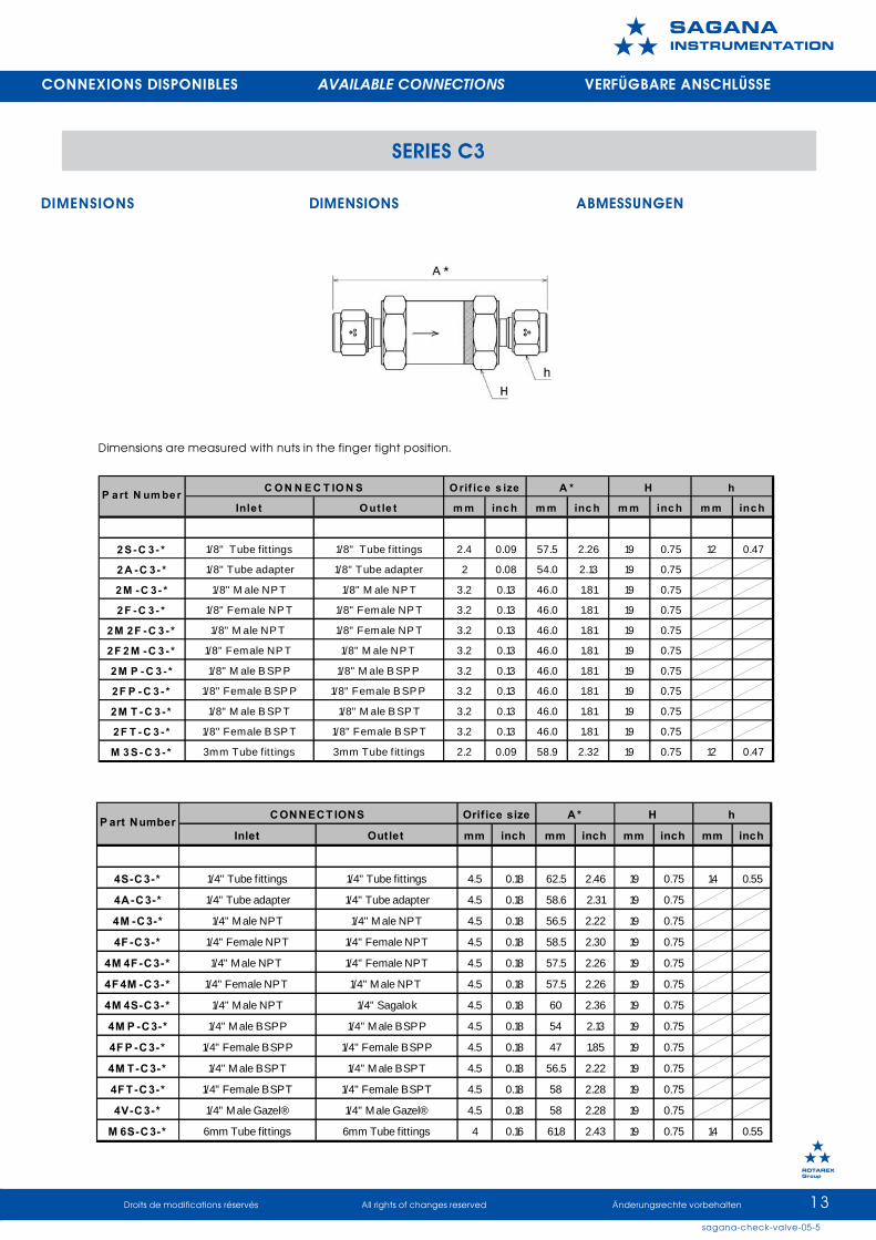
SERIES C3
DESCRIPTION
Les clapets anti-retour série «C3» sontdisponibles avec différents raccords.La pression maximale d’utilisation estde 300 bar pour l’acier inoxydablePression différentielle maximum:200 bar.Différentes pressions d’ouverture sontdisponibles.Une étiquette de couleur indiquela pression d’ouverture.
INFORMATIONS TECHNIQUES
NOMENCLATURE
DESCRIPTION
Series »C3» check valves areavailable with different connectors.The maximum operating pressure is300 bar.Maximum differential pressure:200barDifferent cracking pressures areavailable.A coloured label indicates theopening pressure.
TECHNICAL DATA
BESCHREIBUNG
Die Rückschlagventile der Baureihe«C3» sind mit verschiedenenVerbindungen lieferbar.Der maximale Einsatzdruck beträgt300 bar.Maximaler Differenzialdruck:200 barEs sind verschiedeneÖffnungsdrücke lieferbar.Der Öffnungsdruck wird durch einfarbiges Etikett angezeigt.
TECHNISCHE DATEN
PART LIST NOMENKLATUR
CLAPET ANTI-RETOUR CHECK VALVE RÜCKSCHLAGVENTIL
Acier Inoxydable Stainless steel
Edelstahl
Laiton Brass
MessingPression de service max.
Maximum working pressure Max Betriebsdruck
300 bar ( 4351 psi ) 200 bar ( 2900 psi )
Pression inverse max. Maximum back pressure
Max. Gegendruck300 bar ( 4351 psi ) 200 bar ( 2900 psi )
Δ P MaximumTempérature de service
Temperature range BetriebstemperaturenPression d'ouverture
Cracking pressureöffnungsdruck 40, 50, 100
200 bar ( 2900 psi )Voir le tableau "matière du joint"
See the "Seal material" table Siehe die Tabelle"O-Ringwerkstoff"
1/3, 1, 35, 10, 25
MatièreMaterial
Werkstoff1 Corps d'entrée Inlet body Eingangskörper 316L2 Siège Seat Sitz FPM*3 Support de s iège Seat stand Sitzräger 316L4 Clapet Valve Klappe 316L5 Ressort Spring Feder 3026 Etiquette couleur Colored label Farbetikette PP7 O-ring O-ring O-ring FPM*8 Corps de sortie Outlet body Ausgangskörper 316 L
*For other materials, see the " Seal material" table .
Item Désignation Designation Beschreibung
Ma tiè re du joint Te m pé rature de se rviceSe al Ma teria l Te m pera ture ra ting
0-Ringw e rkstoff Betrie bste m pera ture nFPM -25°C to 200°C
(fluorocarbon Rubber) -13°F to 392°FNBR -30°C to 120°CNitrile -22°F to 248°FEPDM -50°C to 135°C
(ethylene Propy lene Rubber) -58°F to 275°FPTFE* -40°C to 180°C(Teflon) -40°F to 356°F
Ref.
FPM
NBR
EPDM
*PTFE w ill not garanty the tightnes s except when high back pres s ure is applied.*PTFE ne garantit l'étanchéité qu 'avec une contre-pres s ion im portante.*PTFE garantiert d ie D ichtheit nur be i Hochdruck.
PTFE
13sagana-check-valve-05-5
Droits de modifications réservés All rights of changes reserved Änderungsrechte vorbehalten
����������������
���� �����
CONNEXIONS DISPONIBLES AVAILABLE CONNECTIONS VERFÜGBARE ANSCHLÜSSE
DIMENSIONS DIMENSIONS ABMESSUNGEN
SERIES C3
Dimensions are measured with nuts in the finger tight position.
Inle t O ut le t m m inch m m inc h m m inch m m inch
2 S -C 3 - * 1/8" Tube fit tings 1/8" Tube f ittings 2.4 0.09 57.5 2.26 19 0.75 12 0.47
2 A -C 3- * 1/8" Tube adapter 1/8" Tube adapter 2 0.08 54.0 2.13 19 0.75
2M -C 3- * 1/8" M ale NP T 1/8" M ale NP T 3.2 0.13 46.0 1.81 19 0.75
2 F -C 3 - * 1/8" Female NP T 1/8" Female NP T 3.2 0.13 46.0 1.81 19 0.75
2M 2F -C 3 - * 1/8" M ale NP T 1/8" Female NP T 3.2 0.13 46.0 1.81 19 0.75
2F 2 M -C 3 - * 1/8" Female NP T 1/8" M ale NP T 3.2 0.13 46.0 1.81 19 0.75
2M P - C 3 - * 1/8" M ale B SP P 1/8" M ale B SP P 3.2 0.13 46.0 1.81 19 0.75
2F P - C 3 - * 1/8" Female B SP P 1/8" Female B SP P 3.2 0.13 46.0 1.81 19 0.75
2M T - C 3 - * 1/8" M ale B SP T 1/8" M ale B SP T 3.2 0.13 46.0 1.81 19 0.75
2F T - C 3 - * 1/8" Female B SP T 1/8" Female B SP T 3.2 0.13 46.0 1.81 19 0.75
M 3 S - C 3 - * 3mm Tube fit tings 3mm Tube fittings 2.2 0.09 58.9 2.32 19 0.75 12 0.47
P art N um ber hC O N N E C T IO N S O rif ic e s ize A * H
Inlet Outlet mm inch mm inch mm inch mm inch
4S-C3-* 1/4" Tube fittings 1/4" Tube fittings 4.5 0.18 62.5 2.46 19 0.75 14 0.55
4A-C3-* 1/4" Tube adapter 1/4" Tube adapter 4.5 0.18 58.6 2.31 19 0.75
4M -C3-* 1/4" Male NPT 1/4" Male NPT 4.5 0.18 56.5 2.22 19 0.75
4F -C3-* 1/4" Female NPT 1/4" Female NPT 4.5 0.18 58.5 2.30 19 0.75
4M 4F-C3-* 1/4" Male NPT 1/4" Female NPT 4.5 0.18 57.5 2.26 19 0.75
4F4M -C3-* 1/4" Female NPT 1/4" Male NPT 4.5 0.18 57.5 2.26 19 0.75
4M 4S-C3-* 1/4" Male NPT 1/4" Sagalok 4.5 0.18 60 2.36 19 0.75
4M P -C3-* 1/4" Male BSPP 1/4" Male BSPP 4.5 0.18 54 2.13 19 0.75
4F P -C3-* 1/4" Female BSPP 1/4" Female BSPP 4.5 0.18 47 1.85 19 0.75
4M T-C3-* 1/4" Male BSPT 1/4" Male BSPT 4.5 0.18 56.5 2.22 19 0.75
4FT-C3-* 1/4" Female BSPT 1/4" Female BSPT 4.5 0.18 58 2.28 19 0.75
4V-C3-* 1/4" Male Gazel® 1/4" Male Gazel® 4.5 0.18 58 2.28 19 0.75
M 6S-C3-* 6mm Tube fittings 6mm Tube fittings 4 0.16 61.8 2.43 19 0.75 14 0.55
P art Number hCONNECT IONS Orifice size A* H

14sagana-check-valve-05-5
Droits de modifications réservés All rights of changes reserved Änderungsrechte vorbehalten
����������������
���� �����
SERIES C3
CONNEXIONS DISPONIBLES AVAILABLE CONNECTIONS VERFÜGBARE ANSCHLÜSSE
Inlet Outlet mm inch mm inch mm inch mm inch
6S-C 3-* 3/8" Tube fittings 3/8" Tube fittings 7.1 0.28 83 3.27 26 1.02 19 0.75
6A -C 3-* 3/8" Tube adapter 3/8" Tube adapter 7.1 0.28 78.5 3.09 26 1.02
6M -C 3-* 3/8" M ale NPT 3/8" M ale NPT 9.1 0.36 72.2 2.84 26 1.02
6F -C 3-* 3/8" Female NPT 3/8" Female NPT 9.1 0.36 72.2 2.84 26 1.02
6M 6F -C 3-* 3/8" M ale NPT 3/8" Female NPT 9.1 0.36 72.2 2.84 26 1.02
6F 6M -C 3-* 3/8" Female NPT 3/8" M ale NPT 9.1 0.36 72.2 2.84 26 1.02
6M 6S-C 3-* 3/8" M ale NPT 3/8" Tube fittings 7.1 0.28 77.5 3.05 26 1.02
6M 8S-C 3-* 3/8" M ale NPT 1/2" Tube fittings 9.1 0.36 80 3.15 26 1.02
6M P -C 3-* 3/8" M ale BSPP 3/8" M ale BSPP 9.1 0.36 66 2.60 26 1.02
6F P -C 3-* 3/8" Female BSPP 3/8" Female BSPP 9.1 0.36 67.6 2.66 26 1.02
6M T -C 3-* 3/8" M ale BSPT 3/8" M ale BSPT 9.1 0.36 72.2 2.84 26 1.02
6F T -C 3-* 3/8" Female BSPT 3/8" Female BSPT 9.1 0.36 72.2 2.84 26 1.02
M 8S-C 3-* 8mm Tube fittings 8mm Tube fittings 6.4 0.25 82.2 3.24 26 1.02 17 0.67
M 10S-C 3-* 10mm Tube fittings 10mm Tube fittings 7.9 0.31 84 3.31 26 1.02 19 0.75
P art N umber hC ON N EC T ION S Orif ice s ize A * H
Inlet Outlet mm inch mm inch mm inch mm inch
8S-C 3-* 1/2" Tube fittings 1/2" Tube fittings 10 0.39 92 3.62 32 1.26 22 0.87
8A -C 3-* 1/2" Tube adapter 1/2" Tube adapter 10 0.39 94 3.70 32 1.26
8M -C 3-* 1/2" M ale NPT 1/2" M ale NPT 10 0.39 86 3.39 32 1.26
8F -C 3-* 1/2" Female NPT 1/2" Female NPT 10 0.39 87 3.43 32 1.26
8M 8F -C 3-* 1/2" M ale NPT 1/2" Female NPT 10 0.39 86 3.39 32 1.26
8F 8M -C 3-* 1/2" Female NPT 1/2" M ale NPT 10 0.39 86 3.39 32 1.26
8M 8S-C 3-* 1/2" M ale NPT 1/2" Tube fittings 10 0.39 88.8 3.50 32 1.26
8M P -C 3-* 1/2" M ale BSPP 1/2" M ale BSPP 10 0.39 76.3 3.00 32 1.26
8F P -C 3-* 1/2" Female BSPP 1/2" Female BSPP 10 0.39 97.5 3.84 32 1.26
8M T -C 3-* 1/2" M ale BSPT 1/2" M ale BSPT 10 0.39 86 3.39 32 1.26
8F T -C 3-* 1/2" Female BSPT 1/2" Female BSPT 10 0.39 86 3.39 32 1.26
8V-C 3-* 1/2" M ale Gazel® 1/2" M ale Gazel® 10 0.39 89 3.50 32 1.26
M 12S-C 3-* 12mm Tube fittings 12mm Tube fittings 9.5 0.37 92 3.62 32 1.26 22 0.87
P art N umber hC ON N EC T ION S Orifice s ize A * H
Inlet Outlet mm inch mm inch mm inch mm inch
12S-C 3-* 3/4" Tube fittings 3/4" Tube fittings 15.1 0.59 104 4.09 36 1.42 30 1.18
12A -C 3-* 3/4" Tube adapter 3/4" Tube adapter 15.1 0.59 109 4.29 36 1.42
12M -C 3-* 3/4" M ale NPT 3/4" M ale NPT 15.1 0.59 95 3.74 36 1.42
12F -C 3-* 3/4" Female NPT 3/4" Female NPT 15.1 0.59 95 3.74 36 1.42
12M 12F -C 3-* 3/4" M ale NPT 3/4" Female NPT 15.1 0.59 95 3.74 36 1.42
12F 12M -C 3-* 3/4" Female NPT 3/4" M ale NPT 15.1 0.59 95 3.74 36 1.42
12M 12S-C 3-* 3/4" M ale NPT 3/4" Tube fittings 15.1 0.59 101 3.98 36 1.42
12M P -C 3-* 3/4" M ale BSPP 3/4" M ale BSPP 15.1 0.59 96.3 3.79 36 1.42
12F P -C 3-* 3/4" Female BSPP 3/4" Female BSPP 15.1 0.59 89 3.50 36 1.42
12M T -C 3-* 3/4" M ale BSPT 3/4" M ale BSPT 15.1 0.59 98 3.86 36 1.42
12F T -C 3-* 3/4" Female BSPT 3/4" Female BSPT 15.1 0.59 98 3.86 36 1.42
12V-C 3-* 3/4" M ale Gazel® 3/4" M ale Gazel® 15.1 0.59 110.5 4.35 36 1.42
M 20S-C 3-* 20mmTube fittings 20mm Tube fittings 15.1 0.59 105 4.13 36 1.42 32 1.26
M 22S-C 3-* 22mm Tube fittings 22mm Tube fittings 15.1 0.59 105 4.13 36 1.42 32 1.26
P art N umber hC ON N EC T ION S Orif ice size A * H

15sagana-check-valve-05-5
Droits de modifications réservés All rights of changes reserved Änderungsrechte vorbehalten
����������������
���� �����
SERIES C3
CONNEXIONS DISPONIBLES AVAILABLE CONNECTIONS VERFÜGBARE ANSCHLÜSSE
COMMENTCOMMANDER
HOW TO ORDER ZUM BESTELLEN
Example:
8S - 8M - C3 - 3 - SS - NBR1 2 3 4 5 6
Inlet connections Outlet connections Serie Cracking pressure Material O-ring Material
2S - 2A-2M -2F-2MP 2S - 2A-2M -2F-2M P 1/32FP-2MT-2FT-M 3 2FP-2M T-2FT-M3
14S-4A-4M -4F-4M P 4S-4A-4M-4F-4MP
4FP-4M T-4FT-4V-M 6 4FP-4M T-4FT-4V-M6 2
6S-6A-6M -6F-6M P-M 10 6S-6A-6M-6F-6M P-M 10 3 SS FPM *6FP-6MT-6FT-M 8 6FP-6M T-6FT-M8 (Stainless steel)
4 NBR8S-8A-8M -8F-8M P 8S-8A-8M-8F-8MP
8FP-8MT-8FT-8V-M12 8FP-8MT-8FT-8V-M 12 10 B EPDM(Brass)
12S-12A-12M-12F-12MP-M22 12S-12A-12M -12F-12M P-M 22 25 PTFE12FP-12MT-12FT-12V-M20 12FP-12MT-12FT-12V-M 20
4016S-16A-16M-16F-16M P 16S-16A-16M -16F-16M P
16FP-16MT-16FT-16V-M25 16FP-16MT-16FT-16V-M 25 50
100* FPM is the s tandard, you don't have to specify it
C3
Inlet Outle t mm inch mm inch mm inch mm inch
16S-C 3-* 1" Tube fittings 1" Tube fittings 16.7 0.66 117 4.61 42 1.65 38 1.50
16A -C 3-* 1" Tube adapter 1" Tube adapter 16.7 0.66 119 4.69 42 1.65
16M -C 3-* 1" M ale NPT 1" M ale NPT 16.7 0.66 103 4.06 42 1.65
16F -C 3-* 1" Female NPT 1" Female NPT 16.7 0.66 103 4.06 42 1.65
16M 16F -C 3-* 1" M ale NPT 1" Female NPT 16.7 0.66 103 4.06 42 1.65
16F 16M -C 3-* 1" Female NPT 1" M ale NPT 16.7 0.66 103 4.06 42 1.65
16M 16S-C 3-* 1" M ale NPT 1" Tube fittings 16.7 0.66 110 4.33 42 1.65
16M P -C 32-* 1" M ale BSPP 1" M ale BSPP 16.7 0.66 98 3.86 42 1.65
16F P -C 3-* 1" Female BSPP 1" Female BSPP 16.7 0.66 103 4.06 42 1.65
16M T -C 3-* 1" M ale BSPT 1" M ale BSPT 16.7 0.66 103 4.06 42 1.65
16F T -C 3-* 1" Female BSPT 1" Female BSPT 16.7 0.66 103 4.06 42 1.65
16V-C 3-* 1" M ale Gazel® 1" M ale Gazel® 16.7 0.66 106 4.17 42 1.65
M 25S-C 3-* 25mm Tube fittings 25mm Tube fittings 16.7 0.66 119 4.69 42 1.65 25 0.98
P art N umber hC ON N EC T ION S Orif ice size A * H

16sagana-check-valve-05-5
Droits de modifications réservés All rights of changes reserved Änderungsrechte vorbehalten
����������������
���� �����
SERIES C3
CODE COULEUR COLOR CODE FARBCODE
CrackingPressure
1/3 psi Blanc White Weiß1 psi Gris Grey Grau2 psi Jaune Yellow Gelb3 psi Orange Orange Orange4 psi Rose Pink Rosa
10 psi Rouge Red Rot25 psi Brun Brown Braun40 psi Vert Green Grün50 psi Bleu Blue Blau100 psi Noir Black Schwartz
Label Color

17sagana-check-valve-05-5
Droits de modifications réservés All rights of changes reserved Änderungsrechte vorbehalten
����������������
���� �����
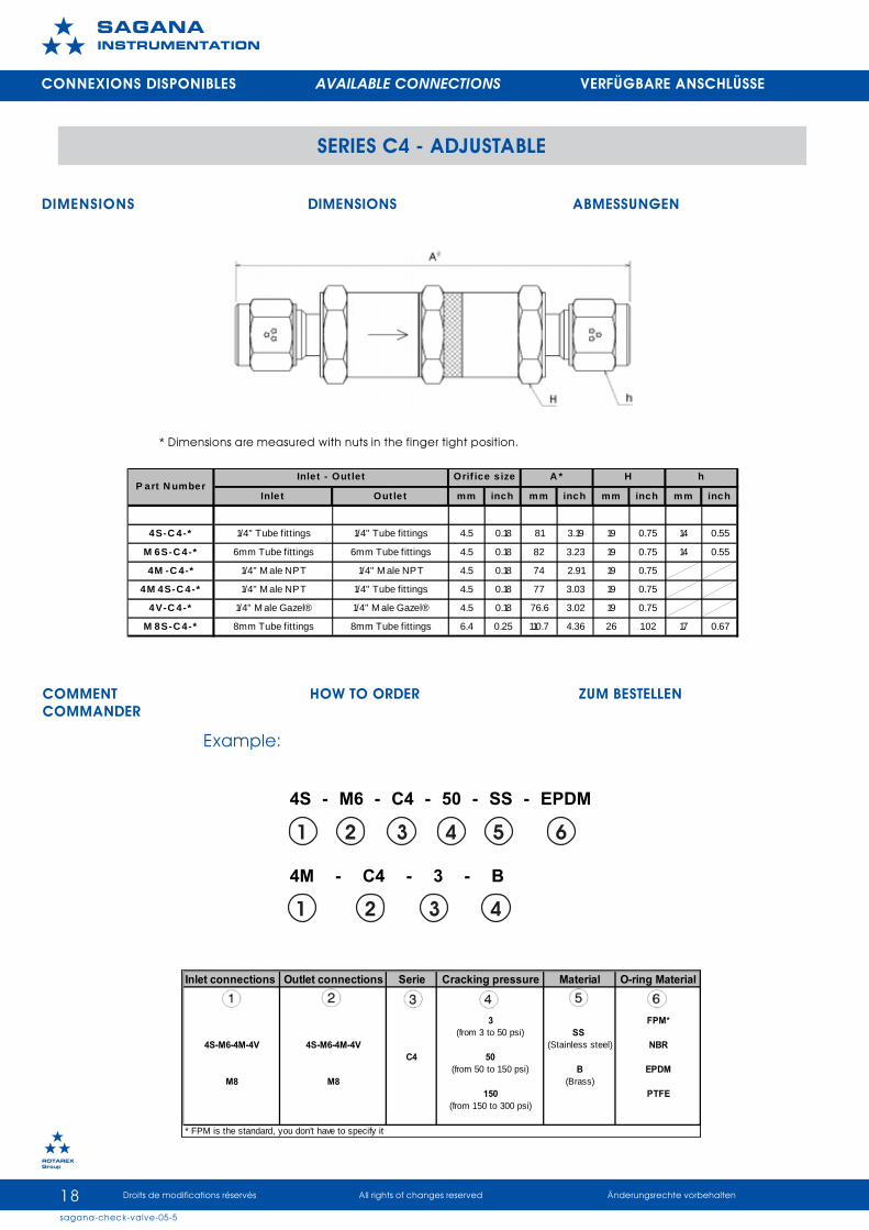
SERIES C4 - ADJUSTABLE
CLAPET ANTI-RETOUR RÉGLABLE ADJUSTABLE CHECK VALVE REGULIERBARES RÜCKSCHLAGVENTIL
DESCRIPTION
Les clapets anti-retour série «C4» sontdisponibles avec différents raccords.La pression maximale d’utilisation estde 300 bar pour l’acier inoxydable.Pression différentielle maximum: 200bar .Différentes pressions d’ouverturesont disponibles par réglage manuel.Une étiquette de couleur indique lapression d’ouverture.
INFORMATIONS TECHNIQUES
NOMENCLATURE
DESCRIPTION
Series «C4» check valves areavailable with different connectors.The maximum operating pressurefor stainless steel is 300 bar.Maximum differential pressure: 200barDifferent cracking pressures areavailable by manual adjustment.A coloured label indicates theopening pressure.
TECHNICAL DATA
BESCHREIBUNG
Die Rückschlagventile der Baureihe«C4» sind mit verschiedenenVerbindungen lieferbar.Der maximale Einsatzdruck beträgt300 bar bei Edelstahl.Maximaler Differenzialdruck200barDurch manuelle Regulierungkönnen verschiedeneÖffnungsdrücke erzielt werden.Der Öffnungsdruck wird durch einfarbiges Etikett angezeigt.
TECHNISCHE DATEN
PART LIST NOMENKLATUR
Acier Inoxydable Stainless steel
Edelstahl
Laiton Brass
MessingPression de service max.
Maximum working pressure Max Betriebsdruck
300 bar ( 4351 psi ) 200 bar ( 2900 psi )
Pression inverse max. Maximum back pressure
Max. Gegendruck300 bar ( 4351 psi ) 200 bar ( 2900 psi )
ΔP Maximum
Température de service Temperature range
BetriebstemperaturenPression d'ouverture
Cracking pressureöffnungsdruck 150 to 350 psi
200 bar ( 2900 psi )
Voir le tableau "matière du joint" See the "Seal material" table
Siehe die Tabelle"O-Ringwerkstoff"3 to 50 psi
50 to 150 psi
1 C o rp s d 'e n t ré e In le t B o d y E in g a n g s k ö rp e r A IS I 3 1 6 L B ra s s2 S iè g e O -rin g S e a t S it z F P M * F P M *3 S u p p o rt s iè g e S e a t s ta n d S it z rä g e r A IS I 3 1 6 L B ra s s4 Jo in t to riq u e O -rin g O -rin g F P M * F P M *5 C la p e t P o p p e t K la p p e A IS I 3 1 6 L B ra s s6 R e s s o rt S p rin g F e d e r 3 0 2 3 0 27 C o rp s c e n tra l C e n te r b o d y C e n t ra l B o d y A IS I 3 1 6 L B ra s s8 E t iq u e t te c o u le u r C o lo re d la b e l F a rb e t ik e t te P P P P9 E c ro u d e ré g la g e A d ju s t in g s c re w A d ju s t in g n u t A IS I 3 1 6 L B ra s s
1 0 Jo in t to riq u e O -rin g O -rin g F P M * F P M *1 1 C o rp s d e s o rt ie O u t le t b o d y A u s g a n g s k ö rp e r A IS I 3 1 6 L B ra s s
*F o r o th e r m a te ria ls , s e e th e " S e a l m a te ria l " ta b le .
W e rk sto ffI te m D é sig n a tio n D e sig n a tio n B e sc h re ib u n g M a te ria l
M a tiè re
Matière du joint Température de serviceSeal Material Temperature rating
0-Ringwerkstoff BetriebstemperaturenFPM -25°C to 200°C
(fluorocarbon Rubber) -13°F to 392°FNBR -30°C to 120°CNitrile -22°F to 248°FEPDM -50°C to 135°C
(ethylene Propylene Rubber) -58°F to 275°FPTFE* -40°C to 180°C(Teflon) -40°F to 356°F
Ref.
FPM
NBR
EPDM
*PTFE will not garanty the tightness except when high back pressure is applied.*PTFE ne garantit l'étanchéité qu'avec une contre-pression importante.*PTFE garantiert die Dichtheit nur bei Hochdruck.
PTFE
18sagana-check-valve-05-5
Droits de modifications réservés All rights of changes reserved Änderungsrechte vorbehalten
����������������
���� �����
SERIES C4 - ADJUSTABLE
CONNEXIONS DISPONIBLES AVAILABLE CONNECTIONS VERFÜGBARE ANSCHLÜSSE
DIMENSIONS DIMENSIONS ABMESSUNGEN
* Dimensions are measured with nuts in the finger tight position.
Inlet connections Outlet connections Serie Cracking pressure Material O-ring Material
3 FPM*(from 3 to 50 psi) SS
4S-M6-4M-4V 4S-M6-4M-4V (Stainless steel) NBRC4 50
(from 50 to 150 psi) B EPDMM8 M8 (Brass)
150 PTFE(from 150 to 300 psi)
* FPM is the standard, you don't have to specify it
COMMENTCOMMANDER
HOW TO ORDER ZUM BESTELLEN
Example:
4S - M6 - C4 - 50 - SS - EPDM
4M - C4 - 3 - B
1 2 3 4 5 6
1 2 3 4
Inle t Outlet mm inch mm inch mm inch mm inch
4S-C 4-* 1/4" Tube fittings 1/4" Tube fittings 4.5 0.18 81 3.19 19 0.75 14 0.55
M 6S-C 4-* 6mm Tube fittings 6mm Tube fittings 4.5 0.18 82 3.23 19 0.75 14 0.55
4M -C 4-* 1/4" M ale NPT 1/4" M ale NPT 4.5 0.18 74 2.91 19 0.75
4M 4S-C 4-* 1/4" M ale NPT 1/4" Tube fittings 4.5 0.18 77 3.03 19 0.75
4V-C 4-* 1/4" M ale Gazel® 1/4" M ale Gazel® 4.5 0.18 76.6 3.02 19 0.75
M 8S-C 4-* 8mm Tube fittings 8mm Tube fittings 6.4 0.25 110.7 4.36 26 1.02 17 0.67
H hP art N umber
Inlet - Out let Orif ice s ize A *

19sagana-check-valve-05-5
Droits de modifications réservés All rights of changes reserved Änderungsrechte vorbehalten
����������������
���� �����
SERIES C4 - ADJUSTABLE
CODE COULEUR COLOR CODE FARBCODE
Cracking Pressure
From 3 to 50 psi WhiteFrom 50 to 150 psi Blue
From 150 to 350 psi Red
Label Color

20sagana-check-valve-05-5
Droits de modifications réservés All rights of changes reserved Änderungsrechte vorbehalten
����������������
���� �����
CLAPET ANTI-RETOUR CHECK VALVE RÜCKSCHLAGVENTIL
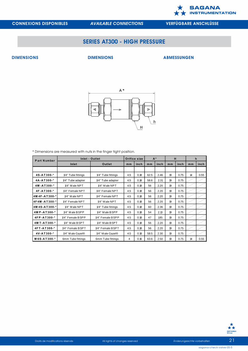
SERIES AT300 - HIGH PRESSURE
DESCRIPTION
Les clapets anti-retour AT-300 sontdisponibles avec différents raccords.La pression maximale d’utilisation estde 300 bar.Différentes pressions d’ouverture sontdisponibles.Une étiquette de couleur indiquela pression d’ouverture.Homologation R110
INFORMATIONS TECHNIQUES
NOMENCLATURE
DESCRIPTION
Check valves AT300 are available withdifferent connectors.The maximum operating pressurefor stainless steel is 300 bar.Different cracking pressures areavailable .A coloured label indicates theopening pressure.Homologation R110
TECHNICAL DATA
BESCHREIBUNG
Das Rückschlagventil AT-300 ist mitverschiedenen Verbindungenlieferbar.Der maximale Einsatzdruck beträgt300 bar bei Edelstahl.Es sind verschiedeneÖffnungsdrücke lieferbar.Der Öffnungsdruck wird durch einfarbiges Etikett angezeigt.Homologation R110
TECHNISCHE DATEN
PART LIST NOMENKLATUR
M a t i è r eM a t e r i a l
W e r k s t o f f1 C o r p s d ' e n t r é e I n l e t b o d y E i n g a n g s k ö r p e r 3 1 6 L2 S i è g e S e a t S i t z F P M *3 S u p p o r t d e s i è g e S e a t s t a n d S i t z r ä g e r 3 1 6 L4 C l a p e t V a l v e K l a p p e 3 1 6 L5 R e s s o r t S p r i n g F e d e r 3 0 26 E t i q u e t t e c o u l e u r C o l o r e d l a b e l F a r b e t i k e t t e P P7 J o i n t t o r i q u e O - r i n g O - r i n g F P M *8 C o r p s d e s o r t i e O u t l e t b o d y A u s g a n g s k ö r p e r 3 1 6 L
* F o r o t h e r m a t e r i a l s , s e e t h e " S e a l m a t e r i a l " t a b l e .
I t e m D é s i g n a t i o n D e s i g n a t i o n B e s c h r e i b u n g
M a tiè re d u jo in t T e m p é r a tu re d e se r v i c eS e a l M a te r ia l T e m p e ra tu re ra tin g
0 -R in g w e rk sto ff B e tr ie b ste m p e ra tu re nF P M -2 5 °C to 2 0 0 °C
(flu o ro c a rb o n R u b b e r) -1 3 °F to 3 9 2 °FN B R -3 0 °C to 1 2 0 °C
N it ri le -2 2 °F to 2 4 8 °FE P D M -5 0 °C to 1 3 5 °C
(e th y le n e P ro p y le n e R u b b e r) -5 8 °F to 2 7 5 °FP TF E * -4 0 °C to 1 8 0 °C(Te flo n ) -4 0 °F to 3 5 6 °F
R e f.
F P M
N B R
E P D M
* P T F E w i l l n o t g a ra n ty th e tig h tn e s s e xc e p t w h e n h ig h b a c k p re s s u re i s a p p l ie d .* P T F E n e g a ra n ti t l 'é ta n c h é i té q u 'a ve c u n e c o n tre -p re s s io n im p o rta n te .* P T F E g a ra n tie r t d ie D ic h th e i t n u r b e i H o c h d ru c k .
P TF E
21sagana-check-valve-05-5
Droits de modifications réservés All rights of changes reserved Änderungsrechte vorbehalten
����������������
���� �����
SERIES AT300 - HIGH PRESSURE
DIMENSIONS DIMENSIONS ABMESSUNGEN
* Dimensions are measured with nuts in the finger tight position.
CONNEXIONS DISPONIBLES AVAILABLE CONNECTIONS VERFÜGBARE ANSCHLÜSSE
Inle t Outlet mm inch mm inch mm inch mm inch
4S-A T 300-* 1/4" Tube fittings 1/4" Tube fittings 4.5 0.18 62.5 2.46 19 0.75 14 0.55
4A -A T 300-* 1/4" Tube adapter 1/4" Tube adapter 4.5 0.18 58.6 2.31 19 0.75
4M -A T 300-* 1/4" M ale NPT 1/4" M ale NPT 4.5 0.18 56 2.20 19 0.75
4F -A T 300-* 1/4" Female NPT 1/4" Female NPT 4.5 0.18 56 2.20 19 0.75
4M 4F -A T 300-* 1/4" M ale NPT 1/4" Female NPT 4.5 0.18 56 2.20 19 0.75
4F 4M -A T 300-* 1/4" Female NPT 1/4" M ale NPT 4.5 0.18 56 2.20 19 0.75
4M 4S-A T 300-* 1/4" M ale NPT 1/4" Tube fittings 4.5 0.18 60 2.36 19 0.75
4M P -A T 300-* 1/4" M ale BSPP 1/4" M ale BSPP 4.5 0.18 54 2.13 19 0.75
4F P -A T 300-* 1/4" Female BSPP 1/4" Female BSPP 4.5 0.18 47 1.85 19 0.75
4M T -A T 300-* 1/4" M ale BSPT 1/4" M ale BSPT 4.5 0.18 56 2.20 19 0.75
4F T -A T 300-* 1/4" Female BSPT 1/4" Female BSPT 4.5 0.18 56 2.20 19 0.75
4V-A T 300-* 1/4" M ale Gazel® 1/4" M ale Gazel® 4.5 0.18 58.5 2.30 19 0.75
M 6S-A T 300-* 6mm Tube fittings 6mm Tube fittings 4 0.16 63.6 2.50 19 0.75 14 0.55
P art N umber hInlet - Out let Orif ice s ize A * H

22sagana-check-valve-05-5
Droits de modifications réservés All rights of changes reserved Änderungsrechte vorbehalten
����������������
���� �����
Inlet connections Outlet connections Serie Cracking pressure Material O-ring Material
2S - 2A-2M-2F-2MP 2S - 2A-2M-2F-2MP 1/32FP-2MT-2FT-M3 2FP-2MT-2FT-M3 1 FPM*
24S-4A-4M-4F-4MP 4S-4A-4M-4F-4MP 3 SS NBR
4FP-4MT-4FT-4V-M6 4FP-4MT-4FT-4V-M6 4 (Stainless steel)10 EPDM
6S-6A-6M-6F-6MP-M10 6S-6A-6M-6F-6MP-M10 256FP-6MT-6FT-6V-M8 6FP-6MT-6FT-6V-M8 40 PTFE
50100
* FPM is the standard, you don't have to specify it
AT300
SERIES AT300 - HIGH PRESSURE
CONNEXIONS DISPONIBLES AVAILABLE CONNECTIONS VERFÜGBARE ANSCHLÜSSE
COMMENTCOMMANDER
HOW TO ORDER ZUM BESTELLEN
Example:
4S - AT300 - 10 - SS - EPDM
1 2 4 5 63
Inlet Outlet mm inch mm inch mm inch mm inch
6S-A T 300-* 3/8" Tube fittings 3/8" Tube fittings 7.1 0.28 83 3.27 26 1.02 19 0.75
6A -A T 300-* 3/8" Tube adapter 3/8" Tube adapter 7.1 0.28 78.5 3.09 26 1.02
6M -A T 300-* 3/8" M ale NPT 3/8" M ale NPT 9.1 0.36 72.2 2.84 26 1.02
6F -A T 300-* 3/8" Female NPT 3/8" Female NPT 9.1 0.36 72.2 2.84 26 1.02
6M 6F -A T 300-* 3/8" M ale NPT 3/8" Female NPT 9.1 0.36 72.2 2.84 26 1.02
6F 6M -A T 300-* 3/8" Female NPT 3/8" M ale NPT 9.1 0.36 72.2 2.84 26 1.02
6M 6S-A T 300-* 3/8" M ale NPT 3/8" Tube fittings 7.1 0.28 77.5 3.05 26 1.02
6M 8S-A T 300-* 3/8" M ale NPT 1/2" Tube fittings 9.1 0.36 80 3.15 26 1.02
6M P -A T 300-* 3/8" M ale BSPP 3/8" M ale BSPP 9.1 0.36 66 2.60 26 1.02
6F P -A T 300-* 3/8" Female BSPP 3/8" Female BSPP 9.1 0.36 67.6 2.66 26 1.02
6M T -A T 300-* 3/8" M ale BSPT 3/8" M ale BSPT 9.1 0.36 72.2 2.84 26 1.02
6F T -A T 300-* 3/8" Female BSPT 3/8" Female BSPT 9.1 0.36 72.2 2.84 26 1.02
6V-A T 300-* 3/8" M ale Gazel® 3/8" M ale Gazel® 7.1 0.28 83.2 3.28 26 1.02
M 8S-A T 300-* 8mm Tube fittings 8mm Tube fittings 6.4 0.25 82.2 3.24 26 1.02 17 0.67
M 10S-A T 300-* 10mm Tube fittings 10mm Tube fittings 7.9 0.31 84 3.31 26 1.02 19 0.75
P art N umber hInlet - Out let Orif ice size A * H

23sagana-check-valve-05-5
Droits de modifications réservés All rights of changes reserved Änderungsrechte vorbehalten
����������������
���� �����
SERIES AT300 - HIGH PRESSURE
CODE COULEUR COLOR CODE FARBCODE
CrackingPressure
1/3 psi Blanc White Weiß1 psi Gris Grey Grau2 psi Jaune Yellow Gelb3 psi Orange Orange Orange4 psi Rose Pink Rosa
10 psi Rouge Red Rot25 psi Brun Brown Braun40 psi Vert Green Grün50 psi Bleu Blue Blau100 psi Noir Black Schwartz
Label Color

24sagana-check-valve-05-5
Droits de modifications réservés All rights of changes reserved Änderungsrechte vorbehalten
����������������
���� �����
SERIES PG
PURGE MANUELLE MANUAL PURGE ENTLÜFTUNGSVENTILE
DESCRIPTION
Les purges manuelles Sagana®sont utilisées pour purger descanalisations, cuves, vannes…La purge peut être ferméemanuellement ou avec une clé.L’écrou de réglage est serti defaçon à empêcher l’expulsion decelui-ci sous pression.Les purges Sagana® sontdisponibles avec différentsraccords.
DESCRIPTION
Sagana® manual purge valves areused to flush out pipe works, tanks,valves …The purge valve can be closedmanually or with a wrench. Theadjusting nut is tightened so as toprevent expulsion under pressure.Sagana® purge valves areavailable with different connectors.
BESCHREIBUNG
Die manuellen Entlüftungsventilevon Sagana® werden zum Ablassenvon Kanalisationen, Wannen,Ventilen usw. eingesetzt.Das Entlüftungsventil kann manuell odermit einem Schlüssel geschlossenwerden. Die Stellmutter istgequetscht, damit sie sich unterDruck nicht öffnet.Die Sagana® Entlüftungsventile sindmit verschiedenen Verbindungenlieferbar.
INFORMATIONS TECHNIQUES TECHNICAL DATA TECHNISCHE DATEN
Inox / Stainless steel / Rostfreier Stahl : PN = 270 bar / 3916 psi
Laiton / Brass / Messing: PN = 200 bar / 2900 psi
Air Cv= 0,04
NOMENCLATURE PART LIST NOMENKLATUR
Stainless Steel Brass1 Ecrous Cap Schraubenmutter 316L Stainless Steel Brass2 Bille Ball Murmel3 Ressort Spring Sprungfeder4 Corps Body Körper 316L Stainless Steel Brass
316L Stainless Steel *302 Stainless Steel
Item Désignation Designation BeschreibungMaterial

25sagana-check-valve-05-5
Droits de modifications réservés All rights of changes reserved Änderungsrechte vorbehalten
����������������
���� �����
SERIES PG
CONNEXIONS DISPONIBLES AVAILABLE CONNECTIONS VERFÜGBARE ANSCHLÜSSE
CONFIGURATIONS CONFIGURATIONS KONFIGURATIONEN
DIMENSIONS DIMENSIONS ABMESSUNGEN
EndConnections mm inch mm inch mm inch (mm) inch
1/ 8" Sagana® T ube f it t ings 2S 33.9 1.33 15.2 0.60 14 0.55 12 0.471/ 4" Sagana® T ube f it t ings 4S 36.3 1.43 17.8 0.70 14 0.55 14 0.553/ 8" Sagana® T ube f it t ings 6S 39.8 1.57 19.3 0.76 14 0.55 19 0.753mm Sagana® T ube f it t ings M3S 33.9 1.33 15.3 0.60 14 0.55 12 0.476mm Sagana® T ube f it t ings M6S 36.3 1.43 17.7 0.70 14 0.55 14 0.5510mm Sagana® T ube f it t ings M10S 39.8 1.57 19.5 0.77 14 0.55 19 0.75
1/ 8" F emale N P T (B SP T , B SP P ) 2F 26.6 1.05 9.5 0.37 14 0.551/ 4" F emale N P T (B SP T , B SP P ) 4F 31.1 1.22 14.3 0.56 19 0.753/ 8" F emale N P T (B SP T , B SP P ) 6F 32.9 1.30 14.3 0.56 22 0.871/ 2" F emale N P T (B SP T , B SP P ) 8F 37.8 1.49 19.1 0.75 27 1.061/ 8" M ale N P T (B SP T , B SP P ) 2M 28.1 1.11 9.5 0.37 14 0.551/ 4" M ale N P T (B SP T , B SP P ) 4M 33.2 1.31 14.3 0.56 14 0.553/ 8" M ale N P T (B SP T , B SP P ) 6M 33.7 1.33 14.3 0.56 19 0.751/ 2" M ale N P T (B SP T , B SP P ) 8M 40 1.57 19.1 0.75 22 0.87
1/ 8" Sagana® T ube adapter 2A 32.2 1.27 13.5 0.53 14 0.551/ 4" Sagana® T ube adapter 4A 35 1.38 15.9 0.63 14 0.553/ 8" Sagana® T ube adapter 6A 36 1.42 17.5 0.69 14 0.553mm Sagana® T ube adapter M3A 32.2 1.27 13.5 0.53 14 0.556mm Sagana® T ube adapter M6A 35 1.38 15.9 0.63 14 0.5510mm Sagana® T ube adapter M10A 36 1.42 17.5 0.69 14 0.55* Dimensions mesured with nut in the finger thight position.
FRef. M* N H

26sagana-check-valve-05-5
Droits de modifications réservés All rights of changes reserved Änderungsrechte vorbehalten
����������������
���� �����
SERIES PG
CONNEXIONS DISPONIBLES AVAILABLE CONNECTIONS VERFÜGBARE ANSCHLÜSSE
COMMENTCOMMANDER
HOW TO ORDER ZUM BESTELLEN
Example:
M6S - PG - E - SS
Purge en coude 90° avec raccordSagana® double bague 6mmMatière = AISI 316L
Purge valve in 90° bend with Sagana®
compression fittings 6mm connectorMaterial = AISI 316L
Entlüftungsventile mit 90° Krümmungund 6mm Sagana®
Doppelringverschraubung.Material = AISI 316L
1 2 3 4
End connections Purge Model Material Ball Thread
2S, 4S, 6SM3S, M6S, M10S S - Straight
J - 45° Elbow SS - Stainless steel P- PTFE BSPP Thread2F, 4F, 6F, 8F PG E - 90° Elbow
2M, 4M, 6M, 8M T - Inline tee B - Brass 316L* BSPT ThreadTU - Angle Tee
2FA, 4FA, 6FA C - UnionM3FA, M6FA, M10FA
*316L is the standard, you don't have to specify it
27sagana-check-valve-05-5
Droits de modifications réservés All rights of changes reserved Änderungsrechte vorbehalten
����������������
���� �����
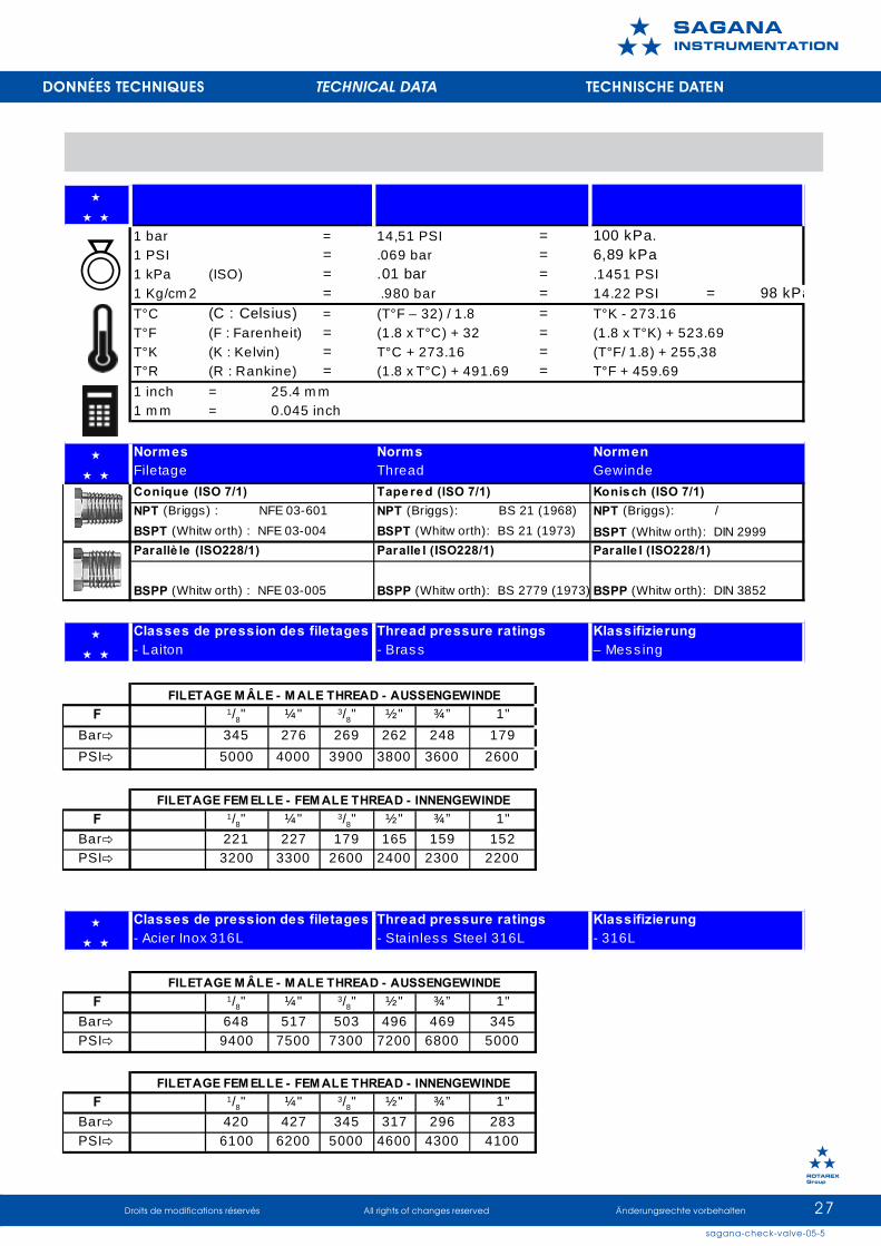
DONNÉES TECHNIQUES TECHNICAL DATA TECHNISCHE DATEN
1 bar = 14,51 PSI =1 PSI = .069 bar =1 kPa (ISO) = .01 bar = .1451 PSI1 Kg/cm 2 = .980 bar = 14.22 PSI = 98 kPaT°C (C : Celsius) = (T°F – 32) / 1.8 = T°K - 273.16T°F (F : Farenheit) = (1.8 x T°C) + 32 = (1.8 x T°K) + 523.69T°K (K : Kelvin) = T°C + 273.16 = (T°F/ 1.8) + 255,38T°R (R : Rankine) = (1.8 x T°C) + 491.69 = T°F + 459.691 inch = 25.4 m m1 m m = 0.045 inch
BSPT (Whitw orth) : NFE 03-004 BSPT (Whitw orth): BS 21 (1973)
F 1/8" ¼" 3/8" ½" ¾” 1"Bar 345 276 269 262 248 179PSI 5000 4000 3900 3800 3600 2600
F 1/8" ¼" 3/8" ½" ¾” 1"Bar 221 227 179 165 159 152PSI 3200 3300 2600 2400 2300 2200
F 1/8" ¼" 3/8" ½" ¾” 1"Bar 648 517 503 496 469 345PSI 9400 7500 7300 7200 6800 5000
F 1/8" ¼" 3/8" ½" ¾” 1"Bar 420 427 345 317 296 283PSI 6100 6200 5000 4600 4300 4100
FILETAGE M ÂLE - M ALE THREAD - AUSSENGEWINDE
FILETAGE FEM ELLE - FEM ALE THREAD - INNENGEWINDE
Classes de pression des filetages Thread pressure ratings Klassifizierung - Acier Inox 316L - Stainless Steel 316L - 316L
FILETAGE M ÂLE - M ALE THREAD - AUSSENGEWINDE
FILETAGE FEM ELLE - FEM ALE THREAD - INNENGEWINDE
Classes de pression des filetages Thread pressure ratings Klassifizierung - Laiton - Brass – Mess ing
BSPP (Whitw orth) : NFE 03-005 BSPP (Whitw orth): BS 2779 (1973) BSPP (Whitw orth): DIN 3852
BSPT (Whitw orth): DIN 2999Parallè le (ISO228/1) Paralle l (ISO228/1) Paralle l (ISO228/1)
Conique (ISO 7/1) Tape re d (ISO 7/1) Konisch (ISO 7/1)NPT (Briggs) : NFE 03-601 NPT (Briggs): BS 21 (1968) NPT (Briggs): /
Normes Norms NormenFiletage Thread Gewinde
100 kPa.6,89 kPa

e-mail: [email protected]
website: www.rotarex.com
����������������
Headquarters Luxembourg
information
���� �����