cl-p002-al14re-a nic l32 manual(intel)...
TRANSCRIPT

FC
CH
A x 1 B x 1 C x 1 D x 1 F x 4 G x 4
Parts List
Install LGA 2011/1366/1155/1156/1150/775 Clip
Installation Preparation
Install Heat-sink
P/N:CL-P002-AL14RE-A
E x 4
I x 1 K x 1H x 4
Installation Manual_Intel
1366 1156/1155/1150 775
A
B
©2013 The rmal take Technology Co. , Ltd. Al l Rights Res erved.
www.thermaltake.com
4 pin
45
76
8
32
B
J
Installation Manual_Intel
O
X
D
D
G
E
E
A
A
B
L x 1 M x 1
1
9
I
M
A
K
L
2
J x 2
B-2013.12
Application for
LGA 2011 / LGA 1366 / LGA 1155 / 1156 / 1150
LGA 775
Applicable aux processeurs suivants :
LGA 2011 / LGA 1366 / LGA 1155 / 1156 / 1150
LGA 775
Aplicación para
LGA 2011 / LGA 1366 / LGA 1155 / 1156 / 1150
LGA 775
Applicazione per
LGA 2011 / LGA 1366 / LGA 1155 / 1156 / 1150
LGA 775
Aplicação para
LGA 2011 / LGA 1366 / LGA 1155 / 1156 / 1150
LGA 775
Anwendung für
LGA 2011 / LGA 1366 / LGA 1155 / 1156 / 1150
LGA 775
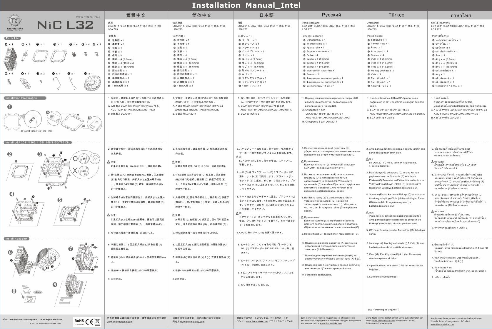
2. When you install Back-plate (D) make sure the
side with the foam is facing the motherboard.
Note:
If you want to install LGA 2011 CPU, proceed to
step 4
3. Insert the four Screws (G) through the Back-
plate (D) and the motherboard and secure them
with Nut (E). Place Bracket (C) onto the Nuts(E)
and secure it with Screw (F). Make sure the Tt
logo on the Bracket (C) is upward facing.
4. Place Nut (E) onto the motherboard and place
the Bracket (C) onto the nuts and secure with 4
Short Screws (H). Make sure the Tt logo on the
Bracket (C) is upward facing.
Note:
If the Bracket (C) is not firmly secured, please
slightly loose the screws (G) and fasten the
screws (F) again.
5. Apply a thin layer of Thermal Grease (B) onto
the CPU.
2. Wenn Sie die Rückwand (D) installieren, stellen Sie
sicher, dass die Seite mit dem Schaum zur
Hauptplatine zeigt.
Anmerkung:
Wenn Sie eine LGA-2011-CPU installieren, gehen
Sie zu Schritt 4.
3. Fügen Sie die vier Schrauben (G) durch die
Rückwand (D) und die Hauptplatine ein und sichern
Sie sie mit Mutter (E). Platzieren Sie die Halterung
(C) auf den Schrauben (E) und befestigen Sie sie
mit der Schraube (F). Stellen Sie sicher, dass das
Tt-Logo auf der Halterung (C) nach oben zeigt.
4. Platzieren Sie die Mutter (E) auf der Hauptplatine
und die Halterung (C) auf den Muttern und sichern
Sie sie mit vier kurzen Schrauben (H). Stellen Sie
sicher, dass das Tt-Logo auf der Halterung (C)
nach oben zeigt.
Anmerkung:
Wenn die Halterung (C) nicht fest gesichert ist,
lockern Sie bitte etwas Schrauben (G) und die
Schrauben (F) wieder an.
5. Tragen Sie eine dünne Schicht Wärmeleitpaste (B)
auf die CPU auf.
2. Al instalar la placa trasera (D), asegúrese de que
el lado con la goma-espuma se halle mirando a la
placa base.
Nota:
Si desea instalar la CPU LGA 2011, vaya al paso 4.
3. Inserte los cuatro tornillos (G) por la placa trasera
(D) y la placa base y fíjelos con las tuercas (E).
Coloque el soporte (C) sobre las tuercas (E) y fíjelo
con los tornillos (F). Asegúrese de que el logo Tt
del soporte (C) esté mirando hacia arriba.
4. Coloque las tuercas (E) en la placa base y coloque
el soporte (C) sobre las tuercas, y fíjelo con los
cuatro tornillos (H). Asegúrese de que el logo Tt
del soporte (C) esté mirando hacia arriba.
Nota:
Si el soporte (C) no está firmemente sujeto, afloje
ligeramente los tornillos de la placa trasera (D) y
apriete nuevamente los tornillos del soporte (C).
5. Aplique una fina capa de lubricante térmico (B) en
la CPU.
2. Quando instala a placa traseira (D), certifique-
se de que o lado com a esponja está virado para
a motherboard.
Nota:
Se pretender instalar um CPU LGA 2011, avance
para a etapa 4.
3. Insira os quatro parafusos (G) através da placa
traseira (D) e a motherboard e fixe com a porca
(E). Coloque o suporte (C) nas porcas E) e fixe
com o parafuso (F). Certifique-se de que o
logótipo Tf no suporte (C) está virado para cima.
4. Coloque a porca (E) na motherboard e coloque o
suporte (C) nas porcas e fixe com 4 parafusos
(H). Certifique-se de que o logótipo Tf no
suporte (C) está virado para cima.
Nota:
Se o suporte (C) não estiver bem fixo, desaperte
ligeiramente os parafusos curtos na placa
traseira (D) e aperte novamente os parafusos
curtos no suporte (C).
5. Aplique uma camada fina de massa térmica (B)
no CPU.
2. Lorsque vous installez la plaque arrière (D)
assurez-vous que le côté avec la mousse fait face
à la carte mère.
Remarque :
Si vous souhaitez installer un processeur LGA
2011, passez à l'étape 4.
3. Insérez les quatre vis (G) à travers la plaque
arrière (D) et la carte mère et fixez-les avec
l'écrou (E). Placez le support (C) sur les écrous
(E) et fixez-le avec la vis (F). Assurez-vous que le
logo Tt sur le support (C) est orienté vers le haut.
4. Placez l'écrou (E) sur la carte mère et placez le
support (C) sur les écrous et fixez-le à l'aide de 4
vis (H). Assurez-vous que le logo Tt sur le support
(C) est orienté vers le haut.
Remarque :
Si le support (C) n'est pas bien fixé, s'il vous plaît
un peu lâche les vis (G) et serrez les vis (F) à
nouveau.
5. Appliquez une fine couche de graisse thermique
(B) sur le processeur.
2. Durante l'installazione della piastra posteriore
(D), accertarsi che il lato gommato sia rivolto
verso la scheda madre.
Nota:
Per installare la CPU LGA 2011, passare alla
procedura 4
3. Inserire le quattro viti (G) attraverso la piastra
posteriore (D) e la scheda madre e fissarle con il
dado (E). Posizionare il supporto (C) sui dadi (E)
e fissarlo con la vite (F). Accertarsi che il logo Tt
sul supporto (C) sia rivolto verso l'alto.
4. Posizionare il dado (E) sulla scheda madre e il
supporto (C) sui dadi e fissare con 4 viti (H).
Accertarsi che il logo Tt sul supporto (C) sia
rivolto verso l'alto.
Nota:
Se il supporto (C) non è fissata saldamente, si
prega leggermente allentate le viti (G) e serrare
le viti (F) di nuovo.
5. Applicare uno strato sottile di grasso termico (B)
sulla CPU.
6. Screw the Heat-sink (A) onto the motherboard
with the Mounting Plate (I) & Mounting Plate
Screws (J) tightly.
7. Fix the Fan (M) onto the Heat-sink (A) with Fan
Clips (K) & (L) separately.
8. Connect the 4-pin wire to the motherboard’s
CPU fan connector.
9. Installation is done.
6. Schrauben Sie den Kühlkörper (A) mit der
Montageplatte (I) & Schrauben (J) auf der
Hauptplatine fest.
7. Befestigen Sie das Gebläse (M) mit den
Gebläse-Clips (K) & (L) separat auf dem
Kühlkörper (A).
8. Verbinden Sie den 4-poligen Stecker mit dem
CPU-Gebläseanschluss auf der Hauptplatine.
9. Die Installation ist vollständig.
6. Fije el difusor de calor (A) en la placa base con
la placa de montaje (I) & tornillos (L) con
fuerza.
7. Fije por separado el ventilador (M) en el
difusor de calor (A) con los ganchos de
ventilador (K) & (L).
8. Conecte el cable de 4 pines al conector del
ventilador de la CPU de la placa base.
9. La instalación está completada.
6. Aparafuse bem o dissipador de calor (A) à
motherboard com a placa de montagem (I) &
Parafusos (J).
7. Fixe a ventoinha (M) ao dissipador de calor (A)
com os clipes da ventoinha (K) & (L) em
separado.
8. Ligue o cabo de 4 pinos ao conector da
ventoinha do CPU da motherboard.
9. A instalação está terminada.
6. Vissez solidement le dissipateur thermique (A)
sur la carte mère avec la plaque de montage (I)
& Vis (J).
7. Fixez le ventilateur (M) sur le dissipateur
thermique (A) avec des clips de ventilateur (K)
& (L) séparément.
8. Branchez le câble à 4 broches sur le connecteur
de ventilateur du processeur de la carte mère.
9. Installation terminée.
6. Avvitare il dissipatore di calore (A) sulla scheda
madre con la piastra di montaggio (I) & Viti (J) in
modo fermo.
7. Fije por separado el ventilador (M) en el difusor
de calor (A) con los ganchos de ventilador (K) &
(L).
8. Collegare il cavo a 4 pin al connettore della
ventola della CPU della scheda madre.
9. L’installazione è completa.
Bitte besuchen Sie unsere
Kundendienstabteilung für weitere technische
Unterstützung oder Updates unter
www.thermaltake.com
Veuillez vous reporter à la Partie Support pour
un support technique ou une mise à jour sur
www.thermaltake.com
Le rogamos que visite nuestra Sección de
Soporte para más soporte técnico o
actualizaciones en www.thermaltake.com
Per maggiore assistenza tecnica o
aggiornamenti, visitare la sezione sull’assistenza
all’indirizzo www.thermaltake.com
Visite a nossa Secção de Apoio para obter mais apoio técnico ou actualizações em www.thermaltake.com
Please visit our Support Section for more
technical support or update at
www.thermaltake.com
A
B
C
D
E
F
G
H
I
J
K
L
M
Cooler x 1
Thermal Grease x 1
Bracket x 1
Back-plate x 1
Nuts x 4
Screws x 4 (9.6nn)
Screws x 4 (13.6mm)
Screws x 4 (16.6mm)
Mounting Plate x 1
Mounting Plate Screws x 2
Fan Clips-A x 1
Fan Clips-B x 1
14cm Fan x 1
Parts list :
1 Refroidisseur
1 Graisse thermique
1 Support
1 Plaque arrière
4 Écrous
4 Vis (9.6mm)
4 Vis (13.6mm)
4 Vis (16.6mm)
1 Plaque de montage
2 Vis
1 Clips de ventilateur –A
1 Clips de ventilateur –B
1 Ventilateur de 14 cm
Liste des pièces:
1 x refrigerador
1 x lubricante térmico
1 x soporte
1 x placa trasera
4 x tuercas
4 x tornillos (9.6mm)
4 x tornillos (13.6mm)
4 x tornillos (16.6mm)
1 x placa de montaje
2 x tornillos
1 x ganchos de ventilador -A
1 x ganchos de ventilador -B
1 x ventilador de 14 cm
Lista de piezas:
Dissipatore x 1
Grasso termico x 1
Supporto x 1
Piastra posteriore x 1
Dadi x 4
Viti x 4 (9.6mm)
Viti x 4 (13.6mm)
Viti x 4 (16.6mm)
Piastra di montaggio x 1
Viti x 2
Fascette per ventola-A x 1
Fascette per ventola-B x 1
Ventole da 14 cm x 1
Elenco componenti:
Refrigerador x 1
Massa térmica x 1
Suporte x 1
Placa traseira x 1
Porcas x 4
Parafusos x 4 (9.6mm)
Parafusos x 4 (13.6mm)
Parafusos x 4 (16.6mm)
Placa de montagem x 1
Parafusos x 2
Clipes da ventoinha-A x 1
Clipes da ventoinha-B x 1
Ventoinhas de 14cm x 1
Lista de peças:
A
B
C
D
E
F
G
H
I
J
K
L
M
Kühler x 1
Wärmeleitpaste x 1
Halterung x 1
Rückwand x 1
Muttern x 4
Schrauben x 4 (9.6mm)
Schrauben x 4 (13.6mm)
Schrauben x 4 (16.6mm)
Befestigungsplatte x 1
Schrauben x 2
Gebläse-Clips-A x 1
Gebläse-Clips-B x 1
14 cm Gebläse x 1
Teileliste:
A
B
C
D
E
F
G
H
I
J
K
L
M
A
B
C
D
E
F
G
H
I
J
K
L
M
A
B
C
D
E
F
G
H
I
J
K
L
M
A
B
C
D
E
F
G
H
I
J
K
L
M
English Deutsch Français Español Italiano Português
1. Before Installation, please verify the CPU platform
and select the appropriate holes for your CPU
socket.
A. Hole A for LGA1366/1156/1155/1150/775 &
AMD FM2/FM1/AM3+/AM3/AM2+/AM2
B. Hole B for LGA 2011
1. Überprüfen Sie bitte vor der Installation die CPU-
Plattform und wählen Sie die entsprechenden
Löcher für Ihren CPU-Sockel.
Loch A für LGA1366/1156/1155/1150/775 &
AMD FM2/FM1/AM3+/AM3/AM2+/AM2
A.
B. Loch B für LGA 2011
1. Antes de la instalación, verifique la plataforma de
la CPU y seleccione los orificios
correspondientes para la toma de su CPU.
Orificio A para LGA1366/1156/1155/1150/775 y
AMD FM2/FM1/AM3+/AM3/AM2+/AM2
A.
B. Orificio B para LGA 2011
1. Antes da instalação, verifique a plataforma do
CPU e selecione os orifícios adequados para a
sua socket CPU.
Orifício A para LGA1366/1156/1155/1150/775 &
AMD FM2/FM1/AM3+/AM3/AM2+/AM2
A.
B. Orifício B para LGA 2011
1. Prima dell’installazione, controllare la
piattaforma CPU e scegliere i fori appropriati per
la presa CPU.
Foro A per LGA1366/1156/1155/1150/775 e
AMD FM2/FM1/AM3+/AM3/AM2+/AM2
A.
B. Foro B per LGA 2011
1. Avant l'installation, veuillez vérifier la plateforme
du processeur et sélectionnez les orifices
correspondant au socket de votre processeur.
Trou A pour LGA 1366/1156/1155/1150/775 &
AMD FM2/FM1/AM3+/AM3/AM2+/AM2
A.
B. Trou B pour LGA 2011
297 mm
444 mm
產品料號
CL-P002-AL14RE-A NiC L32 說明書(intel)
產品名稱 印刷項目 子件料號 發稿日期 版本
105G是X 雙銅單色 無無
其他特殊處理效果表面處理2
厚度(g/m )折數 材質雙面印刷 印刷色彩單面印刷
規格樣式單張 MARKETING CHECK DESIGNPRODUCT GM
Poki
刀模線
藍色線條為尺寸標示,請勿印刷上去!
13/12/10 B
FC
CH
A x 1 B x 1 C x 1 D x 1 F x 4 G x 4
Parts List
Install LGA 2011/1366/1155/1156/1150/775 Clip
Installation Preparation
Install Heat-sink
P/N:CL-P002-AL14RE-A
E x 4
I x 1 K x 1H x 4
Installation Manual_Intel
1366 1156/1155/1150 775
A
B
©2013 The rmal take Technology Co. , Ltd. Al l Rights Res erved.
www.thermaltake.com
4 pin
45
76
8
32
B
J
Installation Manual_Intel
O
X
D
D
G
E
E
A
A
B
L x 1 M x 1
1
9
I
M
A
K
L
2
J x 2
B-2013.12
繁體中文 简体中文 日本語 Русский Türkçe ภาษาไทย
更多相關產品資訊與技術支援,請查詢本公司官方網站
www.thermaltake.com
如需技术支持或更新,请访问我们的支持区域,
网址为 www.thermaltake.com
詳細な技術サポートについては、当社のサポートセ
クション www.thermaltake.com にアクセスしてください。
Для получения более подробной и обновленной
технической информации посетите Раздел поддержки
на нашем сайте www.thermaltake.com
Daha fazla teknik destek almak veya güncellemeler için
lütfen www.thermaltake.com adresinden Destek
Bölümümüzü ziyaret edin.
สำหรับการสนับสนุนทางด้านเทคนิคหรือข้อมูลอัพเดต
โปรดไปที ่ส ่วนสนับสนุนของเราที ่เว็บไซต์
www.thermaltake.com
2. 當安裝背板時,請注意背板 (D) 有泡綿那邊需貼
向主機板。
注意:
如果你是要安裝 LGA2011 CPU,請跳划步驟4。
3. 將4支螺絲 (G) 穿過背板 (D) 和主機板,並用螺母
(E) 對角均均鎖緊,將扣具 (C) 放置於螺母 (E)
上,並用另外4支螺絲 (F) 鎖緊,請確認扣具 (C)
的Tt字樣朝上。
4. 先將螺母 (E) 套在四個腳位上,將扣具 (C) 放置於
螺母E上,並4支短螺絲 (H) 鎖緊,請確認扣具 (C)
的Tt字樣朝上。
注意:
如果扣具 (C) 在螺絲 (F) 鎖緊後,還有可以搖晃的
空間,請先稍微放鬆螺絲 (G) ,再鎖緊螺絲 (F) 。
5. 均勻塗抹薄薄一層導熱膏 (B) 於CPU上。
2. 当安装背板时,请注意背板 (D) 有泡绵那边需贴
向主板。
注意:
如果你是要安装LGA2011 CPU,请跳划步骤4。
3. 将4支螺丝 (G) 穿过背板 (D) 和主板,并用螺母
(E) 对角均均锁紧,将扣具 (C) 放置于螺母 (E)
上,并用另外4支螺丝 (F) 锁紧,请确认扣具 (C)
的Tt字样朝上。
4. 先将螺母 (E) 套在四个脚位上,将扣具 (C) 放置于
螺母E上,并4支短螺丝 (H) 锁紧,请确认扣具 (C)
的Tt字样朝上。
注意:
如果扣具 (C) 在螺丝 (F) 锁紧后,还有可以摇晃的
空间,请先稍微放松螺丝 (G) ,再锁紧螺丝 (F) 。
5. 均匀涂抹薄薄一层导热膏 (B) 于CPU上。
2. После установки задней пластины (D)
убедитесь, что поверхность с пеноматериалом
направлена в сторону материнской платы.
Примечание.
Если выполняется установка ЦП с гнездом
LGA 2011, то перейдите к пункту 4
3. Вставьте четыре винта (G) через заднюю
пластину (D) и материнскую плату и
зафиксируйте их гайкой (E). Установите
кронштейн (C) на гайки (E) и зафиксируйте его
винтом (F). Убедитесь, что логотип Tt на
кронштейне (C) направлен вверх.
4. Вставьте гайку (E) в материнскую плату,
установите кронштейн (C) на гайки и
зафиксируйте его 4 винтами (H). Убедитесь,
что логотип Tt на кронштейне (C) направлен
вверх.
Примечание.
Если кронштейн (C) закреплен ненадежно,
немного ослабьте винты на задней пластине
(D) и снова затяните винты на кронштейне (C).
5. Нанесите на ЦП тонкий слой термосмазки (B).
2. バックプレート (D) を取り付ける時、気泡側がマ
ザーボードの方を向いていることを確認します。
注:
LGA 2011 CPUを取り付ける場合、ステップ4に
移動します。
3. ねじ (G) をバックプレート (D) とマザーボードに
通し、ナット (E) で固定します。ブラケット (C)
をナット (E) に置き、ねじ (F) で固定します。ブラ
ケット (C) の Tt ロゴが上を向いていることを確認
してください。
4. ナット (E) をマザーボードに置き、ブラケット (C)
をナットの上に置き、4本の短ねじ (H) で固定しま
す。ブラケット (C) の Tt ロゴが上を向いているこ
とを確認してください。
注:
ブラケット(C)がしっかりと固定されていない
場合、少し緩いネジ(G)を使って、もう一度ネジ
(F)を固定します。
5. CPU に熱グリース (B) を薄く塗ります。
2. Arka panoyu (D) taktığınızda, köpüklü tarafın ana
karta baktığından emin olun.
Not:
Bir LGA 2011 CPU'su takmak istiyorsanız,
4. adıma ilerleyin.
3. Dört Vidayı (G) arka pano (D) ve ana karttan
geçirerek takın ve Somunla (E) sabitleyin.
Plakayı (C) Somunların (E) üzerine yerleştirin ve
Vidayla (F) sabitleyin. Plaka (C) üzerindeki Tt
logosunun yukarıya baktığından emin olun.
4. Somunu (E) ana kartın ve Plakayı (C) somunların
üzerine yerleştirip 4 Vida (H) ile sabitleyin. Plaka
(C) üzerindeki Tt logosunun yukarıya
baktığından emin olun.
Not:
Plaka (C) sıkı bir şekilde sabitlenmezse lütfen
Arka panodaki (D) vidaları hafifçe gevşetin ve
Plaka (C) üzerindeki vidaları yeniden sıkın.
5. CPU'nun üzerine ince bir Termal Yağ(B) tabakası
sürün.
2. เมื ่อคุณติดตั ้งแผ่นปิดด้านหลัง (D)
กรุณาตรวจสอบว่าได้หันด้านที ่ม ีโฟม
เข้าหาแผงวงจรหลักแล้ว
หมายเหตุ:
ถ้าคุณต้องการติดตั ้งซีพียูร ุ ่น LGA 2011
ให้ข้ามไปขั ้นตอนที ่ 4
3. ใส่สกรู (G) ทั ้ง 4 ตัว ผ่านแผ่นปิดด้านหลัง (D)
และแผงวงจรหลัก แล้วใช้น็อต (E) ขันให้แน่น
วางแบร็กเกต (C) ลงบนน็อต (E) แล้วใช้สกรู (F)
ขันให้แน่น ตรวจสอบว่าได้หันด้านที ่ม ีโลโก้ Tt
บนแบร็กเกต (C) ขึ ้นด้านบนแล้ว
4. ใส่ (E) บนแผงวงจรหลัก แล้ววางแบร็กเกต (C)
ลงบนน็อตเหล่านั ้น จากนั ้น ใช้สกรู (H) ทั ้ง 4
ตัวขันให้แน่น ตรวจสอบว่าได้หันด้านที ่ม ีโลโก้ Tt
บนแบร็กเกต (C) ขึ ้นด้านบนแล้ว
หมายเหตุ:
ถ้าคุณขันแบร็กเกต (C) ไม่แน่นพอ
ให้คลายสกรูบนแผ่นปิดด้านหลัง (D) ออกเล็กน้อย
แล้วขันสกรูให้แน่นอีกครั ้ง บนแบร็กเกต (C)
5. ทาจารบีร้อน (B) บาง ๆ บนซีพียู
6. 以固定扣具 (I) & 固定扣具螺絲 (J)將散熱器 (A)
鎖緊於主機板上。
7. 將風扇 (M) 以風扇線扣 (K) & (L) 安裝於散熱器 (A)
上。
8. 連接4PIN 接線至主機板上的CPU風扇接座。
9. 安裝完成。
6. 以固定扣具 (I) & 固定扣具螺丝 (J)将散热器 (A)
锁紧于主板上。
7. 将风扇 (M) 以风扇线扣 (K) & (L) 安装于散热器 (A)
上。
8. 连接4PIN 接线至主板上的CPU风扇接座。
9.安装完成。
6. Надежно закрепите радиатор (A) винтом на
материнской плате с помощью монтажной
пластины (I) & Винты (J).
7. Поочередно закрепите вентиляторы (M) на
радиаторе (A) с помощью фиксаторов (K) & (L).
8. Подсоедините 4-контактный провод к разъему
вентилятора ЦП на материнской плате.
9. Установка завершена.
6. ヒートシンク (A) を取り付けプレート (I) &
ねじ (J) でマザーボードにねじでしっかり取り付
けます。
7. ヒートシンク (A) にファン (M) をファンクリップ
(K) & (L) で個別に固定します。
8. 4 ピンワイヤをマザーボードの CPU ファンコネ
クタに接続します。
9. 取り付けが完了しました。
6. Isı alıcıyı (A), Montaj levhasıyla (I) & Vida (J) ana
kartın üzerine sıkı bir şekilde vidalayın.
7. Fanı (M), Fan Klipsiyle (K) & (L) Isı Alıcının (A)
üzerine ayrı olarak takın.
8. 4 pimli kabloyu ana kartın CPU fan konektörüne
bağlayın.
9. Kurulum tamamlanmıştır.
6. ขันสกรูฮีตซิงก์ (A)
บนแผงวงจรหลักยึดกับแผ่นสำหรับยึด (I) & สกรู (J)
ให้แน่น
7. ติดตั ้งคลิปพัดลม (M) บนฮีตซิงก์ (A) แยกกัน
โดยใช้คลิปพัดลม (K) & (L)
8. ต่อสายแบบ 4 พิน
เข้ากับขั ้วต่อพัดลมสำหรับซีพียูของแผงวงจรหลัก
9. เสร็จการติดตั ้ง
適用
LGA 2011 / LGA 1366 / LGA 1155 / 1156 / 1150
LGA 775
应用范围
LGA 2011 / LGA 1366 / LGA 1155 / 1156 / 1150
LGA 775
用途
LGA 2011 / LGA 1366 / LGA 1155 / 1156 / 1150
LGA 775
Установка для
LGA 2011 / LGA 1366 / LGA 1155 / 1156 / 1150
LGA 775
Uygulama:
LGA 2011 / LGA 1366 / LGA 1155 / 1156 / 1150
LGA 775
การใช้งานสำหรับ
LGA 2011 / LGA 1366 / LGA 1155 / 1156 / 1150
LGA 775
散熱器 x 1
導熱膏 x 1
扣具 x 1
背板 x 1
螺母 x 4
螺絲 x 4 (9.6mm)
螺絲 x 4 (13.6mm)
螺絲 x 4 (16.6mm)
固定扣具 x 1
固定扣具螺絲 x 2
風扇線扣-A x 1
風扇線扣-B x 1
14cm風扇 x 1
散热器 x 1
导热膏 x 1
扣具 x 1
背板 x 1
螺母 x 4
螺丝 x 4 (9.6mm)
螺丝 x 4 (13.6mm)
螺丝 x 4 (16.6mm)
固定扣具 x 1
固定扣具螺丝 x 2
风扇线扣-A x 1
风扇线扣-B x 1
14cm风扇 x 1
クーラー x 1
熱グリース x 1
ブラケット x 1
バックプレート x 1
ナット x 4
ねじ x 4 (9.6mm)
ねじ x 4 (13.6mm)
ねじ x 4 (16.6mm)
取り付けプレート x 1
ねじ x 2
ファンクリップ-A x 1
ファンクリップ-B x 1
14cm ファン x 1
Охладитель x 1
Термосмазка x 1
Кронштейн x 1
Задняя пластина x 1
Гайки x 4
винты x 4 (9.6mm)
винты x 4 (13.6mm)
винты x 4 (16.6mm)
Монтажная пластина x 1
Винты x 2
Фиксаторы вентилятора-A x 1
Фиксаторы вентилятора-B x 1
Вентиляторы 14 см x 1
Soğutucu x 1
Termal Yağ x 1
Plaka x 1
Arka pano x 1
Somun x 4
Vida x 4 (9.6mm)
Vida x 4 (13.6mm)
Vida x 4 (16.6mm)
Montaj Levhası x 1
Vida x 2
Fan Klipsi-A x 1
Fan Klipsi-B x 1
14cm’lik Fan x 1
ชุดระบายความร้อน x 1
จารบีร้อน x 1
แบร็กเกต x 1
แผ่นปิดด้านหลัง x 1
น็อต x 4
สกรู x 4 (9.6mm)
สกรู x 4 (13.6mm)
สกรู x 4 (16.6mm)
แผ่นสำหรับยึด x 1
สกรู x 2
คลิปพัดลม-A x 1
คลิปพัดลม-B x 1
พัดลมขนาด 14 ซม. x 1
零件表 : 部件列表: 部品リスト: Список деталей Parça listesi: รายการชิ ้นส่วน:
A
B
C
D
E
F
G
H
I
J
K
L
M
A
B
C
D
E
F
G
H
I
J
K
L
M
A
B
C
D
E
F
G
H
I
J
K
L
M
A
B
C
D
E
F
G
H
I
J
K
L
M
A
B
C
D
E
F
G
H
I
J
K
L
M
A
B
C
D
E
F
G
H
I
J
K
L
M
1. 安裝前,請確認正確的 CPU 系統平台後選擇適合
的 CPU 孔位,並注意扣具擺放方向。
A. A 鎖點為 LGA1366/1156/1155/1150/775 &
AMD FM2/FM1/AM3+/AM3/AM2+/AM2
B. B 鎖點為 LGA2011
1. 安装前,请确认正确的 CPU 系统平台后选择适合
的 CPU 孔位,并注意扣具摆放方向。
A. A 锁点为 LGA1366/1156/1155/1150/775 &
AMD FM2/FM1/AM3+/AM3/AM2+/AM2
B. B 锁点为 LGA2011
1. Перед установкой проверьте платформу ЦП
и выберите отверстия, подходящие для
используемого гнезда ЦП.
Отверстие A для
LGA1366/1156/1155/1150/775 и
AMD FM2/FM1/AM3+/AM3/AM2+/AM2
A.
B. Отверстие B для LGA 2011
1. 取り付け前に、CPUプラットフォームを確認
し、CPUソケット用の適切な穴を選択します。
A. LGA1366/1156/1155/1150/775 および
AMD FM2/FM1/AM3+/AM3/AM2+/AM2用穴 A
B. LGA 2011用穴 B
1. Kurulumdan önce, lütfen CPU platformunu
doğrulayın ve CPU soketiniz için uygun delikleri
seçin.
LGA1366/1156/1155/1150/775 ve
AMD FM2/FM1/AM3+/AM3/AM2+/AM2 için Delik A
A.
B. LGA 2011 için Delik B
1. ก่อนที ่จะติดตั ้ง
กรุณาตรวจสอบแพลตฟอร์มของซีพียู
และเลือกรูที ่เหมาะสมสำหรับซ็อกเก็ตซีพียูของคุณ
รู A ใช้สำหรับ LGA1366/1156/1155/1150/775 &
AMD FM2/FM1/AM3+/AM3/AM2+/AM2
A.
B. รู B ใช้สำหรับ LGA 2011
297 mm
444 mm
產品料號
CL-P002-AL14RE-A NiC L32 說明書(intel)
產品名稱 印刷項目 子件料號 發稿日期 版本
105G是X 雙銅單色 無無
其他特殊處理效果表面處理2
厚度(g/m )折數 材質雙面印刷 印刷色彩單面印刷
規格樣式單張 MARKETING CHECK DESIGNPRODUCT GM
Poki
刀模線
藍色線條為尺寸標示,請勿印刷上去!
13/12/10 B