civilian conservation corps · vertical scale if the mountains or hills are pronounced in the area...
TRANSCRIPT
UNITED STATES DEPARTMENT OF THE INTERIOR
CIVILIAN CONSERVATION CORPS
PROJECT TRAINING
CONSTRUCTION OF
RELIEF MODELS
P.T. SERIES NO. 10

16476
UNITED STATES DEPARTMENT OP TIE INTERIOR Civilian Conservation Corps
Office of the Supervisor - Project Training
Washington
The Construction of
PELIE? MODELS
This text was written by Howard E. Rothrock, Assistant Chief, Naturalist Division, Branch of Research and Education, in the National Park Service, early in 1936, and had some distribution at that tine. At our request he now has revised the hook for our use in project training.
The use of relief models increases rapidly, and they are constantly being made for new purposes. Thus, the making of those models in the technical services affords opportunity for training which has lead to some very good jobs, and will do the same for many other en-rolleos who show aptitude for the work. To become an adept and versatile model builder cadis for far more than merely manual skill under close supervision, and. an enrollee who takes it up in earnest must look forward to unrelenting study and research in a wide variety of fields.
Mr. Rothrock wishes to aclmowlod.ge with gratitude assistance given by George Robinson of the Engineering Laboratory, U. S. Army; Donald C. Barton and Ered H. Caiobe of the Humble Oil and Refining Company; also by George II. Chadwick, Consulting Geologist, Cat skill, New York, and Earl A. Trager, Chief, Naturalist Division; by Eranklin C. Potter, Associate Geologist; Edward A. Taubert, Inspector; William Macy, Superintendent of the Port Hunt Model Laboratory, Virginia; Ned J. Burns, Acting Chief, Museum Division, all of the National Park Service, and by others who offered suggestions end criticism. She author is indebted to the Western Museum Laboratories at Berkeley, California, for most of the illustrations.
Prepared for, and with the cooperation of, the Technical Services.
December, 1937
16476
rirjsx
Subject Page.
Assembling the Sheets or Laminations 16
Base or Frame for Casting 20, 22
Construction Operations 9 Assembling the Sheets 16 Contour Intervals 11 Cutting the Sheets 16 Dimensions 6, 7, 8 Finishing the Model 24 Gluing the Sheets 16 Methods 9 Registering the Sheets 14 Scales 4, 5, 6, 7, 8 Supporting Plaster Cast in Frame 22
Contour Intervals 11
Costs Cardboard Sheets 12 Wallboard 12
Crew 1, 2
Cut t ing the Sheets 16
Dimensions of Models (Table) 6, 7, 8
Dra f t ing Tables 2
Equipment 1, 2 Cut awl 2 Dra f t ing Tables 2 Glue 16 Knives 16 Lantern S l ides 14 P r o j e c t o r 12
F i n i s h i n g the Model 24
Gluing the Sheets 16
Grids 4 Heavy-l ine 4 L i g h t - l i n e 4
Laminat ions, Cardboard Thicknesses of Sheets 9, 11
i

16476
i i
Sub .loot Page
M a t e r i a l s and Suppl ies Cardboard fo r Laminations (Sheets) 9, 11 Glue 16 lumber f o r Base 20, 22 Papier-mache 22 P l a s t e r 18 , 20, 22 P l a s t i c s 18, 20, 22
Topographic Ojuadrangres 9
Molds 20, 22
Photographing Maps 12
Plaster 18, 20, 22
Formulas 18, 20
Positive Castings 22
Projecting Maps on Sheets 12
Registering the Sheets 14 Reinforcing the Plaster
Scrim 20, 22 Wire Screening 18, 22
Scales 4, 5, 6, 7, 8 Scales of Existing Models 6, 7, 8 Horizontal 5, 6, 7, 8 Vertical 5, 6, 7, 8
Sheets (See Laminations) 9, 11
Supporting Plaster Cast in Frame 22
Symbols for Culture 26
Tools (See Equipment)
For a 5~man crew 2
Topographic Map Needed 4 Contour Intervals 11 Topographic Contour Intervals U.S.G.S. 4, 9
Tracing 12, 14
Uses of Model 1 As a Model 18 As a Pattern 20 As a Study Map 20 As a Mold 20
16476
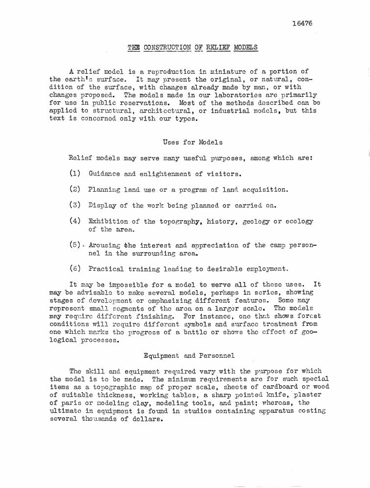
THE CONSTRUCTION OF RELIEF MODELS
A relief model is a reproduction in miniature of a portion of the earth's surface. It may present the original, or natural, condition of the surface, with changes already made by man, or with changes proposed. The models made in our laboratories are primarily for use in public reservations. Most of the methods described can be applied to structural, architectural, or industrial models, but this text is concerned only with our types.
Uses for Models
Relief models may serve many useful purposes, among which are:
(1) Guidance and enlightenment of visiters.
(2) Planning land use or a program of land acquisition.
(3) Display of the work being planned or carried on.
(4) Exhibition of the topography, history, geology or ecology of the area.
(5) Arousing the interest and appreciation of the camp personnel in the surrounding area.
(o) Practical training leading to desirable employment.
It may be impossible for a model to serve all of those uses. It may be advisable to make several models, perhaps in series, showing stages of development or emphasizing different features. Some may represent small segments of the area on a larger scale. The models may require different finishing. For instance, one that shows forest conditions will require different symbols and surface treatment from one which markc the progress of a battle or shows the effect of geological processes.
Equipment and Personnel
The skill and equipment required vary with the purpose for which the model is to be made. The minimum requirements are for such special items as a topographic map of proper scale, sheets of cardboard or wood of suitable thickness, working tahles, a sharp pointed knife, plaster of paris or modeling clay, modeling tools, and paint; whereas, the ultimate in equipment is found in studios containing apparatus costing several thousands of dollars.

16476
The fol lowing m a t e r i a l and equipment have "been recommended for a 5-man crew i n an a r t i c l e "by the Fo res t Se rv i ce :
Crew
1 Tracer 1 Cutter 1 Bu i lde r 2 Modelers
Equipment
4 Drafting Tables 1 Table (tracing) 1 " for building of model 1 " " cutting of cardboard 1 " " modeling
The drafting tables should be well-built, and sufficiently large to accommodate the largest : ection to be constructed, with sufficient space on the sides for tools, etc.
1 International Cut-awl 2 dozen #5 Chisels 1 Oilstone 1 Small- Hammer 1 P l i e r s , sharp-nose , w i th s ide c u t t i n g edge 2 s e t s of Modeling Tools 1 S t ra igh tedge 1 Paper Knife 1 Pocket Steel Tapes Carbon Paper Stylus or 6 H Pencils Chip Board (This board can be purchased from any large paper
house, in several sizes and in approximately 20 different thicknesses.)
Brads, needlepoint (can be obtained from any picture framing house.) Nails 3/4" length Orange Shellac Alcohol
1 Paint Brush 2" width Plastino - Gray (French modeling clay—non-hardoning) Plywood 3/16" to l/4" in thickness.
3

w
Finished Relief Model, Great Smoky Mountains National Park.

16476
Topographic Map Needed
Eefcre a relief model can he made, a topographic map of the area must be supplied. A special or master map should be prepared from which the model can be made. This should be compiled on a good grade of tracing cloth to show only the contours which are to be reproduced on the model, the drainage and the reference data, such as boundary lines, latitude and longitude, grid or triangulation points. All other information is omitted in order to simplify the work of the tracer. Blackline prints or photographs can be made from this map as desired to meet the requirements of the tracers and cutters.
Prints made by one of the dry-print -processes, such as the Ozalid process, arc preferable to blue, blue-line or Van "Dyke prints, as the former do not shrink as much as the wet-developed maps.
Two rectangular grids of reference lines, one set being heavier than the other, should be drawn upon the map.
The primary, or heavy-line grid, divides the map into rectangles equal to the usable area of the sheets of material employed in the construction of the model. (A narrow margin is usually left around each sheet to care for slight overlaps of contours, mashed edges of cardboard, etc.) If the sheets are square, this grid likewise will be square. If they are oblong, the grid will be oblong, also.
The secondary, cr light-line grid, is drawn to form squares within the primary grid. These lines aid in orienting the lamination when, the primary grid, has been cut away. They are also useful as guides in photographing the map when lantern slides are made. If the sheet is square, these lines may be drawn so as to divide it into quarters. If the sheet is oblong, the short dimension should he bisected end this half-width should be used in laying off the squares.
The United States topographic maps, particularly those of the newer surveys which are made to the scale 1:62500 or larger, will usually be found sufficiently accurate for making the master map. If a topographic survey must be made, the contour interval need be no smaller than can be shown on the model. The model cannot be more accurate than the map, hence, care is required not only in the survey but in making the master map from which the model is to be made. If the model is to be on a different scale from that of the original map, the map can be enlarged by replotting the- survey, cr bv photostat or photographic methods.
Choice of Scales
The purpose of the model is to present a bird1s-eye view of a large area, as in the model of Great Smoky Mountains National Park on page 5. For some uses, such as landscape or general land use plan-
4

16476
ning, geological exhibits, dam construction or engineering problems, the model should be constructed accurately and to the same vertical and horizontal scale, so that distances and slopes may be measured directly from the model. For other uses, such as for the guidance of visitors, other geological exhibits, and historical displays, the model should be made so that it will have a pictorial quality. In dioramas this quality is obtained by the use of perspective. In relief models this pictorial quality can be gained with an illusion created by exaggerating or reducing the vertical scale. The model can be made to "loo]: natural" to the observer.
Horizontal Scale
The horizontal scale will be determined by the size of the area to be mapped, the amount of detail desired, and the space which can be allotted to the model. For instance, if the area is one mile square and the model is to be four feet square, then the horizontal scale will be: 4 feet - 1 mile or 111320.
It is usually advisable to include in the model a portion of the terrain surrounding the area really concerned, not only as a means of maintaining the spectator's interest, but also to show the relation of the particular area to the surrounding areas. The width of this framing strip will depend upon the use for which the mode?, is intended. If it is to bo used for the guidance of the visitors or for general planning,' a relatively small scale and a limited amount of detail will be advisable. If the model is to be used for special studios by the technicians, the amount of detail should be determined beforehand, and a suitable horizontal scale chosen.
Vertical Scale
If the mountains or hills are pronounced in the area to be mapped, the vertical sca'e should be the same as the horizontal scale. This choice of scale is well illustrated, by the relief models of Grand Canyon, Great Smoky Mountains, the High Plateau of Utah; and as adapted to smaller areas, it is shown by the models of Ice Spring Craters, Fredericksburg, Penasco Blanco Ruins. These models are listed in Table I, on page 7, together with others that are of approved design. The dimensions and scales of these models are given in this table along with other information.
If It is necessary to emphasize certain surface features, as when mountains or hills are low, or v/hen the model is intended to simulate an actual view of the area, it may be advisable to exaggerate the vertical scale. As has been stated previously, the amount of exaggeration is a matter of judgment only, but the success of the model may depend upon it. An exaggeration of three times the actual is the maximum permitted. The following general relations will assist in determining the vortical scaleJ
5
16475
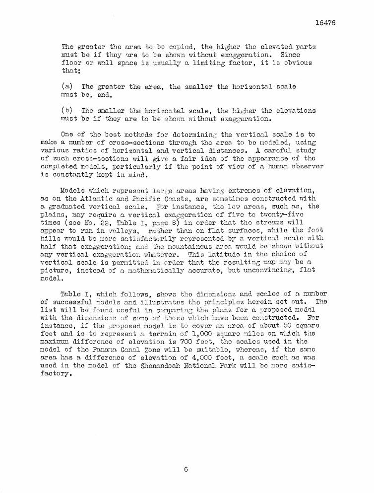
The greater the area to ho copied, the higher the elevated parts must he if they are to he shown without exaggeration. Since floor or wall space is usually a limiting factor, it is ohvious that;
(a) The greater the area, the smaller the horizontal scale must he, and,
(h) The smaller the horizontal scale, the higher the elevations must he if they are to he shown, without exaggeration.
One of the hest methods for determining the vertical scale is to make a number of cross—sections through the area, to ho modeled, using various ratios of horizontal and vertical distances. A careful study of such cross-sections will give a fair idea of the appearance of the completed models, particularly if the point of view of a human observer is constantly kept in mind.
Models which represent large areas having extremes of elevation, as on the Atlantic and Pacific Coasts, are sometimes constructed with a graduated vertical scale. Per instance, the low areas, such as, the plains, nay require a vertical exaggeration of five to twenty-five times (see No. 22, Table I, page 8) in order that the streams will appear to run in valleys, rather than on flat surfaces, while the foot hills would he more satisfactorily represented by a vortical scale with half that exaggeration; and the mountainous .area, would he shown without any vertical exaggeration whatever. This latitude in tho choice of vertical scale is permitted in order that the resulting nap may he a picture, instead of a mathematically accurate, hut unconvincing, flat model.
Table I, which follows, shows the dimensions and scales of a number of successful models and illustrates the principles herein set out. The list will bo found useful in comparing the plans for a proposed model with the dimensions of some of those which have heen constructed. Por instance, if the proposed model is to cover an area, of about 50 square feet and is to represent a terrain of 1,000 square miles on which the naximun difference of elevation is 700 feet, the scales used in the model of the Panama Carnal Zone will he suitable, whereas, if the sane area has a difference of elevation of 4,000 feet, a scale such as was used in the model of the Shenandoah national Park will he more satis-fac to ry.
6
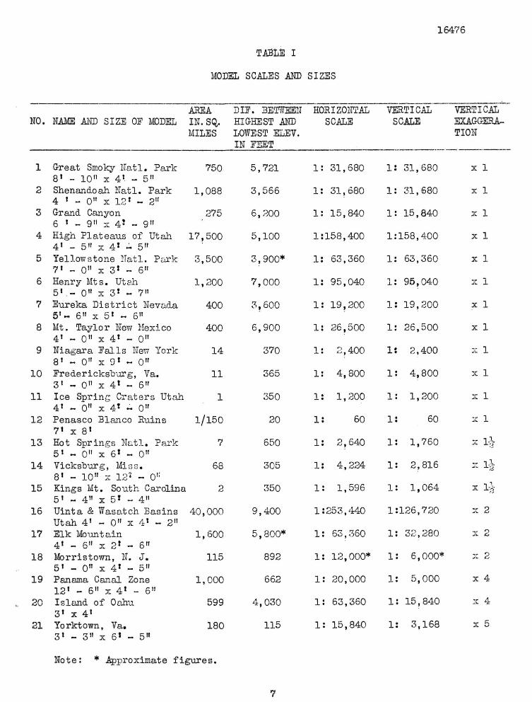
TABLE I
MODEL SCALES AND SIZES
16476
NO.
1
2
3
4
5
6
7
8
9
10
11
12
13
14
15
16
17
18
19
30
21
NAME AND SIZE OE MODEL
Grea t Smoky N a t l . P a r k 8» - 1 0 " x 4 ' - 5 " Shenandoah N a t l . P a r k 4 » - 0" x 12* - 2" Grand Canyon 6 ' - 9 " z 4 J - 9 " High P l a t e a u s of Utah 41 _ 5 " x 4 1 - 5 " Y e l l o w s t o n e N a t l . P a r k 7 ' - 0" x 3* - 6" Henry M t s . Utah 5 ' . - 0" X 3* - 7" E u r e k a D i s t r i c t Nevada 5 ' - 6" x 5 ' - 6" Mt. T a y l o r New Mexico 4 ' - 0 " x 4* - 0" N i a g a r a P a l l s New York 8 ' - 0" x 9 ' « 0" F r e d e r i c k s b u r g , Va. 31 „ 0" x 4 1 - 6" I c e S p r i n g C r a t e r s U t a h 41 .. 0" x 4* ~ 0" P e n a s c o B l a n c o R u i n s 7« x 8 ' Hot S p r i n g s N a t l . P a r k 51 m 0" x 6 1 - 0M
V i c k s b u r g , M i s s . 8 ' - 1 0 " :; 1 2 ' - 0 , :
Kings Mt. Sou th Carol ina 51 _ 411 x 5* - 4 " U i n t a & Wasa t ch B a s i n s U t a h 4 ' - 0" x 4 ' - 2 " E l k Mounta in 4« - 6" x 2 1 - 6" M o r r i s t o w n , N. J . 51 _ 0" x 4 ' - 5 " Panama Canal Zone 1 2 ' - 6" x 4 ' - 6" I s l a n d of Oahxt 3 ' x 4 ' Yorktown, Va. 3 ' - 3 " x 6« - 5 "
AREA IN. SQ. MILES
750
1 ,088
275
1 7 , 5 0 0
3 , 5 0 0
1 ,200
400
400
14
11
1
1 /150
7
68
2
4 0 , 0 0 0
1 ,600
115
1 ,000
599
180
DIP. BETWEEN HIGHEST AND LOWEST FfuEV. IN PEET
5 , 7 2 1
3 , 5 6 6
6 , 2 0 0
5 , 1 0 0
3 , 9 0 0 *
7 , 0 0 0
3 , 6 0 0
6 , 9 0 0
370
365
350
20
650
305
350
9 , 4 0 0
5 , 8 0 0 *
892
662
4 , 0 3 0
115
HORIZONTAL SCALE
11 3 1 , 6 8 0
1 : 3 1 , 6 8 0
1 : 1 5 , 8 4 0
1 : 1 5 8 , 4 0 0
1 : 6 3 , 3 6 0
11 9 5 , 0 4 0
11 1 9 , 2 0 0
11 2 6 , 5 0 0
1 : 2 , 4 0 0
1 : 4 , 8 0 0
l : 1 ,200
l : 60
1 : 2 , 6 4 0
11 4 , 2 2 4
11 1 ,596
1 : 2 5 3 , 4 4 0
1 : 6 3 , 3 6 0
IS 1 2 , 0 0 0 *
11 2 0 , 0 0 0
IS 6 3 , 3 6 0
IS 1 5 , 8 4 0
VERTICAL SCALE
18 3 1 , 6 8 0
IS 3 1 , 6 8 0
IS 1 5 , 8 4 0
1 : 1 5 8 , 4 0 0
IS 6 3 , 3 6 0
IS 9 5 , 0 4 0
IS 1 9 , 2 0 0
IS 2 6 , 5 0 0
11 2 , 4 0 0
IS 4 , 8 0 0
l : l , 2 0 0
IS 60
15 1 ,760
IS 2 , 8 1 6
l : 1 ,064
1 : 1 2 6 , 7 2 0
IS 3 2 , 2 8 0
IS 6 , 0 0 0 *
15 5 , 0 0 0
IS 1 5 , 8 4 0
IS 3 , 1 6 3
VERTICAL MMfSBBX-TION
x 1
X 1
X 1
X 1
X 1
X 1
X 1
X 1
X 1
X 1
X 1
X 1
x 1-}
x 16}
A Xp
x 2
x 2
x 4
- r ,-1
-•». X
x 5
Note: * Approximate f i g u r e s .
7

16476
TABLE I (Continued)
EXAMPLES OE A GRADUATED VERTICAL SCALE
SO.
22
23
NASI AID SI2E OE MODEL
Sta te of New Jerseys ' - 0" x 2 ! ~ 0"
S t a t e of Kentucky
HORIZONTAL SCALE
1:316,800
1:253,440
VERTICAL E ELE
FROM
1 100 200
0 600 800
1,000
XAGGERATIO VATION
TO
100 200
1,800
600 800
1,000 4 ,000
N FOR VARYING ZONES EXAGGERATION (OE IJLSV. )
x 33 .0 x 16 .5 x 11 .0
x 12 .5 x 10 .0 x 7 .5 x 5 .0
8

15-17C
C0"ST5UCTI0IT I£BTH3DS
Constant experimentation is improving our methods of construction. The general procedure is here outlined, hut no attempt is made to recount details of the technique; they vary too much among plants and wo risers. Most of those outlined are "based upon the common practices in manual training and are easily understood.
If the model is a largo one, it can he made in sections, suitable precautions being taken to insure matching at the contacts of the sections.
The baso board upon which the model is built should extend on all sides beyond the model and should represent a definite base-level. This serves to emphasise the topography and supplies a base from which to work. This projecting base-level should appear on the final casting or model and may bo used for descriptive or decorative material, as on page 3.
The construction methods will also vary with the purpose for which the model is made. If only one model is to be made, the base must be solidly constructed and thoroughly varnished or shellacked in order to keep out all possible moisture. The laminations must be permanently fastened together and made moisture-proof and a durable mastic must be used to fill in the laminations. If the model is to servo only as a pattern from which a mold is to be cast, less permanent methods of assembling may be used.
Laxri nations
The model is built up by means of a number of shoots of cardboard, venoer, paper or other suitable material of uniform thickness, called laminations. Each lamination represents a definite contour interval and each one is cut in the shape of the contour vmich it represents. Then these laminations aro added in the ordor of their relative elevation, they present the topography in a series of steps. See page 10. The steps are then filled in to make a smooth slope.
The thickness of the laminations depends upon: (l) the contour interval, and (2) the vertical scale which has been chosen for the model. Eor instance, a contour interval of 10 foot on a model with a vertical scale of 1 inch - 500 foet would be represented by a lamination l/50th of an inch in thickness. Such fine laminations are of doubtful value in pictorial models. Greater contour intervals, such as 20, 50 or even 100 foot intervals should be \ised. The topograpliic sheets issued "by the United States Geological Survey usually show sufficient detail for the construction of models. It is also evident that the contour interval chosen will depend
9

Pattern of Sequoia. Relief Model in Process of Construction. The terrain is represented by superimposed cardboard laminations, shaped according to contours (foreground), and then smoothed to simulate the slope of the ground by filling in the steps (background ).
10

16476
upon a practical balance between the character of the terrain, the size of the model and the thickness of material available for the laminations.
It may be desirable to use more than one unit interval if a variety of terrain is to be represented, Por instance, a 20-foot interval may be used in flat country, and an interval which is 100 feet or greater in the rug-god country.
In or dor to simplify the choice of scale and materia]-, Table II gives the thicknesses in inches of certain contour intervals for vertical scales.
Material which, corresponds to these tliiclmesses can be obtained in caxdboardi brietol—board," railroad—board, fibre-board, wall-board, wood veneer, plywood or similar materials.
Laminations of Cardboard
The United States Government Printing Office carries a complete stock of the first three items and is prepared to supply thicknesses from .009 to .400 of an inch. This material is classified by weight and different lots differ slightly in thickness, hence no constant table of thicknesses can be given. A request may be made- to that
11
T/L3LS II
C0HTOUH INTERVALS
Vertical Scales Thicknesses of laminations — Inches
_ _ _ _ . , _ • _ - ^ ~VTsTJt ~T?3Qt
U.S. Topographic 1:125,000 .001 .00.2 ~ .005 .010 Sheets 1:62,500 .00.2 .004 .010 .019
Other maps 1" - 1 mile 1:63,360 .002 .004 .009 .019 2" - 1 mile 1:31,630 .004 .007 .013 .033 3" - 1 rnilo 1:21,120 .006 .011 .023 .057 4" - 1 mile 1:15,340 .003 .015 .053 .076 5" - 1 mile 1:12,672 .009 .019 .047 .095 6" - 1 mile 1: 10,560 .011 .023 .057 .114 1" - 300' 1: 9,500 .012 .025 .052 .125 8 » - l mile 1: 7,920 .015 .030 .075 .151 1" - 500' 1: 6,000 .020 .040 .050 . 20
12" - 1 mile 1; 5.280 .023 .045 .114 .227 1" - 500' 1: 3,500 .033 .087 .157 .333 1" - 200' 1: 3,400 .050 .100 .250 .500

16476
office for prices and samples of the thicknesses required. The sheets vary in size from 21" x 31" in the lighter weights, to 30" x 40" in the heavier varieties. Some of the lighter bristol-boards occur in rolls, 33" wide.
The cost per thousand sheets, f. o. b. Washington is approximately as follows}
Wall or fibre board such as Celotex, Masonite etc. can be obtained in thicknesses varying from l/8 inch upward. Quotations from the schedule of November 1, 1935 to October 31, 1936 were as follows:
Fibre or Wall 3oard Specifications:
Schedule Size Thickness in Price per
Number in Feet inches Sq. foot
Laminated
59-W-100 4 ' x 6 ' to 16 ' 3 / l 6 .02389 59-W-1C5 4 ' x 6> to 16' l / 4 X)2875 59-W-110 4 ' x 6 ' to 16 ' 5/16 .037 59-W-115 4 ' x 6' to 16 ' 3/8 .03989
No n-Lami nat e d
59-W-125 4 ' x 8' to 10 ' l / 8 .04989 59-W-125 4 ' x 12' l / 8 .04789 59-W-130 4 ' x 8 ' to 10' 3 / l 6 .0659 59-W-130 4 ' x 12 ' 3/16 .0639 59-W-135 4 ' x 12 ' l / 4 .0882
Tracing Contours
The contour is traced upon the cardboard sheet from the topographic map. If the map is the same scale as the model, the copy can be made with carbon paper.
A more accurate result is obtained by the following method* The map is photographed, usually in sections. By means of a projector the picture is thrown upon a wall or easel to which the
12
Approximate Cost pe r 1/100 inch
Ma te r i a l Thickness f o r 1,000 shee t s
B r i s t o l Board . 0 1 to . 05 $11.00 50$ Bag Index Board .08 to .16 3.00 Ra i l road Board .10 to .40 2 .00
Wallboard;
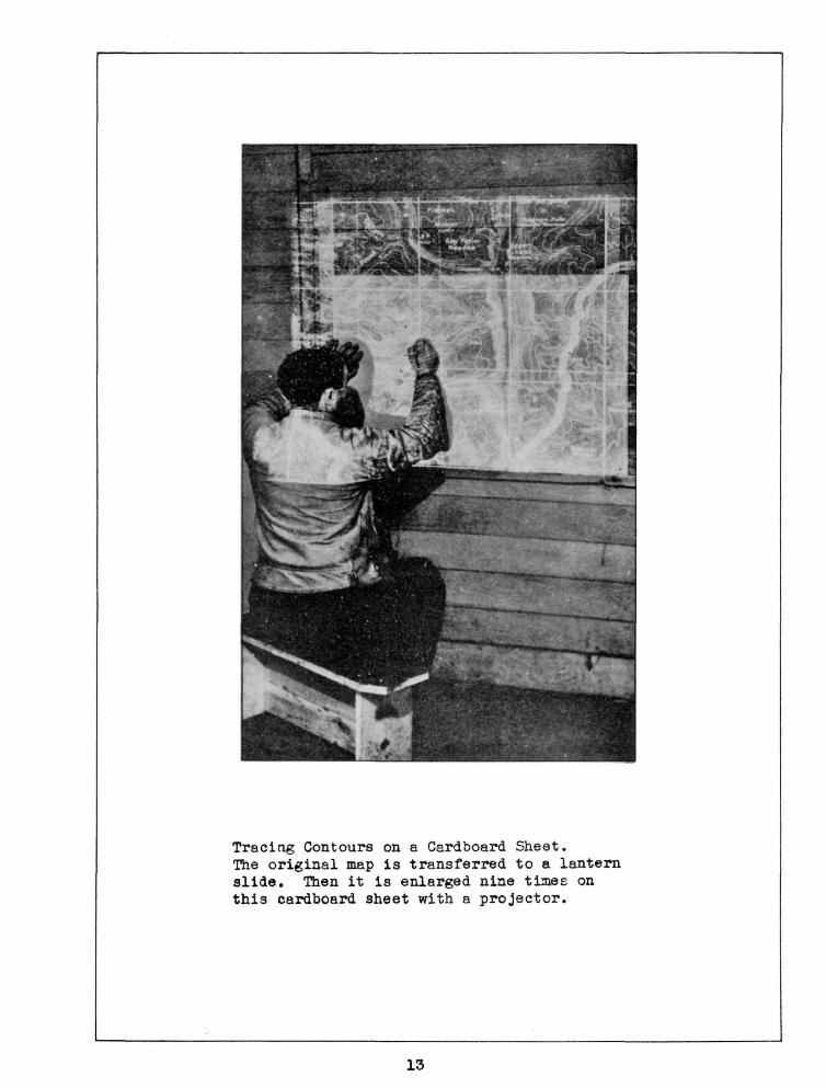
Tracing Contours on a Cardboard Sheet. The original map is transferred to a lantern slide. Then it is enlarged nine times on this cardboard sheet with a projector.
13

16476
cardboard sheet is fastened, and the contours are traced directly onto them. This method is shown on page 13.
The advantages of this method are its greater accuracy and the ease with which any amount of enlarging or reducing can ha done. Of course, it calls for special equipment, with more ex-pence. Costly equipment is not essential. A fairly good camera and a projector which will not distort the image are the principal items.
The extreme edge of each negative is not used unless the camera has a lens of high quality, as poor lenses distort the margins of the picture. When using ordinary cameras it is advisahle to utilize no more than the middle two-thirds of the negative area. Each picture, therefore, must he taken so that it overlaps the adjoining picture by one-third. The secondary grid, heing drawn as squares, will aid greatly in adjusting the camera so that consocutivo portions of the map will appear in tho part of the negative where greatest accuracy will bo ootainod.
Lantern slides may first be made from the photographs. If they are negative, they will project as white lines on a black background and will not be dazzling. If the slides are positives, it will be necessary for the tracer to wear amber glasses to protect his eyes from the strain of the bright reflection.
The tracing and cutting should begin with the lowest contour. Points on the next higher contour are also traced at tho same time to make it easy to place the next higher sheet accurately.
It is often advisable, especially in flat country, to traco tho positions of rivers and lakes as guides to later work.
Each sheet should be marked to show tho elevation for which it stands.
Registration
Two contours thus appear on each sheet. The outside contour is the guide upon which the sheet is cut. The inside one, which maybe only points on the line, is a guide for placing the next sheet. This is called registering the sheet. As a further aid to proper registering, each lamination should be marked with a rectangular t;rid of latitude and longitude lines, and these lines matched up before the sheet is fastened in place. Each Lamination should bear a number which corresponds to the elevation of its contour. All measurements on each sheet should be made from these grid lines.
14

Using a Cutawl to Shape Cardboard Sheets for a Relief Model.
15

16476
Cutting the Sheets
Each lamination is cut along the outside contour.
A knife or jig-saw may be used but the best tool for very thick cardboard is a power jig-saw or a machine known as a "Cutawl,1' See page 15. The best hand knife is one commonly used by leather workers, sturdy, with a short, wide blade. The knife is held vertically in the fist with the thumb up so that maximum prossure can bo applied with minimum effort. The knife is useful for trimming after any other operation.
If the prints from which the model is to be made are the same scale as the model itself, the process of tracing the contours may be eliminated by the following procedure:
The section of the map which is to be reproduced is fastened lightly on the sheet of cardboard or other lamination material. Only that portion of the map need be fastened, which will be the margin of the finished lamination. 7/ith the lowest contour as a guide the map and the sheet are cut through to form the first lamination of the model.
The map is now carefully stripped from this sheet and fastened to the next sheet. With the next higher contour as a guide \he sheet is cut out and, after the map has been stripped off, it will constitute the second lamination.
The process is continued until the whole map has been reproduced in the laminations.
Assembling the Sheets
The sheets are assembled on a wooden frame. They are glued in place, and. fastened firmly by nails. They can be nailed only, if precautions are taken to insure firmness and prevent mashing of the laminations. Only glue which will not soak into the cardboard and make it swell may be used.
If the laminations ore relatively thick a waterproof glue such as casin or casco glue can be used without danger of distorting the lamination. If the lamination is thin, however, rubber cement or shellac should be used. Even shellac will distort thin cardboard or paper unless some of the alcohol is evaporated from it, but the process should not be carried so far that the shellac becomes too thick to handle. A method of exciting pressure on the sheets while being glued is shown on page 17.
16

Gluing Down Contour Laminations. This is an improvised press made for the purpose with a 2 x 4 set in supports so that it can be weighted as much as desired. Care should be taken to distribute the pressure over the entire area of the laminations being glued.
17

16476
As a model
If the model is to he used as made, — not to serve as a form for casting others, — the edges of the laminations are roughened to increase adhesion of the plaster. The edges may he treated, with shellac, varnish or asphaltum to prevent swelling or contraction. The model can he made more durable by tacking: fine wire screening over the laminations before any plaster is applied., except where it will modify steep and rugged topography.
The steps formed by the assembled laminations are now filled with modeling clay, plasticine, some form of plaster of parie, or similar material. It gives a hard surface which can he sanded down after it has set. Simple plaster of paris, plaster of paris mixed with glue or alum to harden it, or with a little vinegar or glue water to delay the setting action will also serve the purpose. Alum should he used sparingly because it tends to harden the set.
The quantity of subsidiary materials should he determined by experimentation because it will differ somewhat with the materials used and with the size of the job. A small model can he cast or covered quickly and hence the setting time need not he delayed greatly. But a large model will require a plaster that will not set so rapidly. The amount of plaster which should be prepared will vary with the size of the model, the relief of the topography and the plasticity of the mixture. The plaster should he proportioned to set slowly enough to permit the preparation of a sufficient amount for the entire casting. The volume required will equal approximately the area, of the model times the estimated average thickness of the plaster, plus at least 10$ for waste and errors in estimating.
Two formulas for plaster follow:
FOBMULa A
Waterproof glue 1 part Hater 5 parts
This mixture is added to approximately equal parts of Gilders Whiting and Po\"dered Asbestos until a. consistency suited to working conditions is obtained.
The above mixture is made over heat, and kept warm while being used. Its consistency is plastic or putty-like mixture where it is applied like modeling clay. A thinner, more liquid consistency is used for flat surfaces or thin sections and may be applied by brush. It will remain workable over a long period providing the surface is kept moist.
18
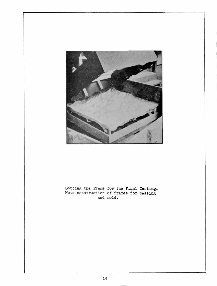
Setting the Frame for the Final Casting. Note construction of frames for casting
and mold.
19

16476
70KMULA 3
Dextrine* yellow 1 part "by volume • Powdered asbestos 3 parts by volume Plaster 2-3 parts by volume depending; water to the desired consistency on how soon it is required
to have the mixture sot
Formula "B" can be prepared without heating* and if it is kept moist, other layers or extensions can be added to it. It is said to be less subject to checking than Formula "A".
Both formulas can be carved and sanded after they have set.
As a Pattern
If the model is to be used as a pattern from which additional models can be made* the steps formed by the laminations can be filled with some kind of modeling clay. This material does not require the rapid handling that plaster of paris does, and it can be reworked as often as is necessary. If the pattern is pointed up with plaster of paris it is shellacked and the rougher portions are lubricated so that the model will not stick when it is removed. Vaseline* cylinder oil, lard oil and soft soap have teen used as lubricating material. Whatever substance is chosen, care should be exercised against leaving brush marks or uneven patches which wo\ild reproduce in the model.
As a Study Map
If the model is to serve as a "study map", it is sometimes advisable not to fill in the contour steps, in order that relative elevations in various sections of the area may be easily compared by the designer. A special mold may be cast from the laminated pattern from which study maps may be cast, after which the model may be completed.
Making the Mold
A wooden base must be made for the mold, and this base is supported above the pattern in such a way that it can be firmly connected to the mold when it is cast.
Slow—setting plaster is usually used for casting the mold. This plaster should be fluid enough to run down the steep slopes and fill all crevices and irregularities in the surface.
The layer of plaster should be from one to two inches thick and should be reenforced. by scrim (hemp) which can be worked into
20

Mold of Acadia National Park Relief Model and Frame Support for a posi
tive Casting.
21

16476
it after it has "been poured and "before it has set. Scrim may be obtained by shredding rope, and strands of it should protrude from the plaster in order that the mold may be tied to the wooden supporting frame. After the plaster has set the mold can be lifted from the model, but it is not thoroughly dry for about a week. If any cavities have been formed by air bubbles on the surface of the mold, they must be filled with plaster. After the cast is thoroughly cured, the mold is shellacked. Positive castings can now be made from this mold, which must be thoroughly lubricated for each use.
Waking A Positive Casting
A wooden base must first be made, as for the mold. See pages 19 and 21. If the cast will require reenforcirg, some of it can be supplied by cross members of this base, which can be cut out where they might get too close to the suiface of the model. Along the upper edge of this base, the outline of which conforms to the contour of the model, a row of smell nails is inserted or wire screening is attached, so that the plaster will be firmly anchored to the e^ge of tne frame.
Scrim and plaster are used in the positive just as in the mold, or the plaster nay be reenforced by strips of burlap, window screening or chicken wire. The casting is usually supported in the middle by strands of scrim or burlap which have been soaked in plaster and tied to the cross members of the frame before the plaster has set. After the cast has set, it is removed from the mold and allowed to cure for at least one week, after which, it is shellacked and painted. See page 23.
Although plaster is an ideal casting material, it is heavy, soft, and subject to breakage. Papier-mache is a lighter and more resilient material and has boon used very s-accessfully in commercial models. The macho can be made from newspaper pulp and gluo. It is applied in thin layers which are tamped into the mold and shellacked. Reenforcement material can be introduced whore necessary.
An alternative method has been recommended in which the casting is built in the mold by means of strips of paper. Tissue paper loused next to the uold and in areas of sharp relief. Hbavier varieties of paper strips are used on the more gentle curves and in the backing of the model. Each strip is pressed into the mold and its exposed surface painted with shellac or glue. Other strips, crossing at various places and angles, are added and similarly treated. Thus a light, rigid casting of paper laminations is built up. Some experimentation would be necessary to determine the best lubricant to keep this carting from sticking; in the mold.
The above materials are satisfactory for models that are protected from the weather and vandalism. If the model is to be placed
22

23
Painting Details on a Relief Model.

16475
out of doors or is to be unattended, it should he cast from more durable materials such as concrete or metal, hut the weight of these two materials and the difficulty in handling them restrict their use. If metal spraying equipment is available, the plaster model can he given a thin coating of copper, brass, or Lionel metal and thus he made very durable.
Three important stages in the construction of a model are shovm on page 25. On the left are the patterns built up from laminated contours. In the centre is the mold or negative and on the right is the finished sectional model.
Finishing the Model
The finishing of the model calls for all the ingenuity at the command of the staff, and will require much time and thought. Final corrections in the topography and minute but expressive features of the landscape c m be tooled into the model. It is then thoroughly sized to make it impervious and to prepare the surface for coloring. The remainder of the finish will depend upon the ground cover and the purpose, for which the model is constructed.
Line work and coloring can be transferred on to the model by free—hand methods, supplemented by available drafting instruments.
A moro rapid procedure is obtained if the comploto map is photographed and a lantern slido made. The slide is then projected on the model while tho artist paints. This procedure has been described by Mr. Quebe, formerly of the Humble Oil and Refining Company, in a personal communication to the author, as follows:
"A projector with a lens having an effective focal length somewhere between seven (7) and twelve (12) inches, and a lamp not smaller than 500 W. should be suitable. Projectors having only a single projection lens should be avoided. The distortion from such a lens is too great for this work.
"Considerable care must be used to locate the projector properly. This may be accomplished by moving the projector back or forth until the grid lenses are properly spaced in the center of the imago. Then up or down and left or right until the lenses are properly spacod around tho outside of the imago. The image can then bo shifted, or rotated slightly to bring it into register.
"A brief description of how the lantern slides for the E. 0, & R. Company maps of Texas were made may be of some interest to those attempting to do their ovm photographic work.
24

Three Stages in the Preparation of a Relief Model, On the left is the cardboard and clay pattern; in the center is the plaster mold or negative and on the right is the complete sectional map.
25
26
"The naps being photographed were about 8' square. Sections about 24" x 30" were photographed by moving the nap about over the easel rather than moving the camera,. The image on the slide should be about 2" x 2v", if larger, the spherical distortion from most projection lens becomes quite noticeable.
"The Fanchromatic Process negative material and the slow lantern slides plates were both developed in Eastman's D-13 Tropical process developer, hardened in Hardener SB-4 and fixed in fixing a formula E-5. Several other process developers and hardeners were tried but the above proved to be the most satisfactory."
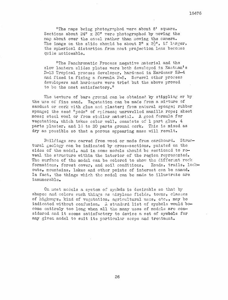
The texture of bare ground can be obtained cy stippling or by the use of fine sand. Vegetation can be made from a mixture of savdust or cork with glue and plaster; from natural sponge; rubber sponge; the seed "pods" of spiraea; unravelled manilla rope; sheet moss; steel wool or from similar material. A good formula for vegetation, which takes color well, consists of 1 part glue, 4 parts plaster, tend 15 to 20 parts ground cork. This is mixed as dbry as possible so that a porous appearing mass will result.
Buildings are carved from wood or made from cardboard. Structural geology can be indicated by cross-sections, painted on the sides of the model, and in some models should be sectioned to reveal the structure within the interior of the region represented. The surface of the model can be colored to show the different rock formations, forest cover, and soil conditions. Eoads, trails, lookouts, mountains, lakes and other points of interest can be named. In fact, the things which the model can be made to illustrate are innumerable.
On most models a system of symbols is desirable so that by shapes and colors such things as airplane fields, towns, classes of highways, kind of vegetation, agricultural uses, etc., may be indicated without confusion. A standard list of symbols would become entirely too long when all the many uses of models are considered and it seems satisfactory to devise a set of symbols for any given model to suit its particular scope and treatment.
1S475