civil aviation publication cap 15 rnp apch · the instrument approach chart will clearly identify...
TRANSCRIPT

CIVIL AVIATION PUBLICATION
CAP 15
RNP APCH
INDEX

This Page Intentionally Left Blank

CCIIVVIILL AAVVIIAATTIIOONN PPUUBBLLIICCAATTIIOONNSS
CAP 15 i 01 May 2010
CAP 15
RNP APCH
INDEX Section Title Page No. 1. Purpose ................................................................................................................... 1 2. Background ............................................................................................................ 1 3. Scope ....................................................................................................................... 2 4. Reference Documents ............................................................................................ 2 5. Assumptions ........................................................................................................... 2 5.1 Navaid Infrastructure ............................................................................................... 3 5.2 Obstacle Clearance .................................................................................................. 3 5.2.1 RNP APCH Without Barovnav Guidance ............................................................... 3 5.2.2 APV Barovnav ......................................................................................................... 3 5.3 Publications.............................................................................................................. 3 5.4 Communication, ATS Surveillance and ATC Coordination ................................... 3 5.5 Service Provider Assumption for APV Barovnav Operation .................................. 4 6. RNP APCH Airworthiness Criteria ..................................................................... 4 6.1 General ..................................................................................................................... 4 6.2 Equipment Qualification .......................................................................................... 4 6.2.1 General ..................................................................................................................... 4 6.2.2 Altimeter Sensor Requirement for APV Barovnav Operation ................................ 5 6.3 Accuracy .................................................................................................................. 5 6.3.1 Horizontal ................................................................................................................ 5 6.3.2 Vertical Accuracy for APV Barovnav Operation. ................................................... 6 6.4 Integrity.................................................................................................................... 8 6.5 Continuity of Function ........................................................................................... 10 7. Functional Criteria .............................................................................................. 11 7.1 Required Function for RNP APCH ....................................................................... 11 7.2 Additional Required Functions for APV Barovnav............................................... 13 7.3 Recommended Function for RNP APCH .............................................................. 14 7.4 Recommended Function for APV Barovnav Operation ........................................ 15 8. Airworthiness Compliance .................................................................................. 15 8.1 General ................................................................................................................... 15 8.2 New or Modified Installations ............................................................................... 15 8.2.1 Specific Installation Criteria .................................................................................. 15 8.3 Existing Installations ............................................................................................. 17 8.4 Specific Installation Assessment ........................................................................... 17 8.4.1 Lateral and Vertical Fly-By Transition Mechanism .............................................. 17 8.4.2 Enhanced Navigation Displays .............................................................................. 18 8.4.3 Intermixing of Equipment ..................................................................................... 18
CCIIVVIILL AAVVIIAATTIIOONN PPUUBBLLIICCAATTIIOONNSS
CAP 15 ii 01 May 2010
9. Aircraft Flight Manual/Pilot Operating Handbook ......................................... 18 10. RNP APCH Operational Criteria ...................................................................... 19 10.1 Flight Operations Documentation.......................................................................... 19 10.2 Flight Crew Training ............................................................................................. 20 10.3 Aerodrome Competence and Operator Verification .............................................. 20 10.4 Navigation Database Management ........................................................................ 21 10.4.1 Operator Involved in Commercial Operations ...................................................... 21 10.4.2 Operator Not Involved in the Commercial Operations.......................................... 21 10.5 Reportable Events .................................................................................................. 21 11. Application & Approval Process ........................................................................ 22 11.1 Pre-application Meeting......................................................................................... 22 11.2 Application ............................................................................................................ 22 11.3 Supporting Documentation .................................................................................... 22 11.4 Approval ................................................................................................................ 23 11.5 Cancellation of RNP APCH Approval .................................................................. 24 Appendix 1 Definitions ................................................................................................... APP 1-1 Appendix 2 Operational Characteristics of the Procedure and Operational Use .... APP 2-1 Appendix 3 Alternate Navigation Database Integrity Check ..................................... APP 3-1 Appendix 4 Operational Procedures ............................................................................ APP 4-1 Appendix 5 Flight Crew Training Syllabus ................................................................. APP 5-1

CCIIVVIILL AAVVIIAATTIIOONN PPUUBBLLIICCAATTIIOONNSS
CAP 15 1 01 May 2010
1. PURPOSE
This CAP provides an acceptable means that can be used to obtain airworthiness approval of an Area Navigation (RNAV) system based on a Global Navigation Satellite System (GNSS) standalone receiver or multisensory system including at least one GNSS sensor in order to conduct RNP Approach (RNP APCH) operations. RNP APCH procedures are characterised by existing charted RNAV (GNSS) approach procedures designed with straight final approach segments. This CAP also defines operational criteria necessary to conduct safely RNP APCH operations in designated European airspace. This CAP addresses RNP APCH operation without vertical guidance (Non Precision Approach operation) and with vertical guidance based on barometric vertical navigation (APV BAROVNAV operation). Final approaches utilising SBAS (Localiser Performance with Vertical guidance (LPV) operation) are addressed in separate CAP material. APV BAROVNAV systems are based on barometric altimetry for the determination of the aircraft position in the vertical axis. The final approach segment of VNAV instrument flight procedures are performed using vertical guidance to a vertical path computed by the onboard RNAV system. The vertical path is contained in the specification of the instrument procedure within the RNAV system navigation database. For other phases of flight, barometric VNAV provides vertical path information that can be defined by altitudes at fixes in the procedure. It should be noted that there is no vertical requirement in this CAP associated to the use of VNAV guidance outside of the final approach segment. Vertical navigation on the initial or intermediate segment can be conducted without VNAV guidance. An applicant may elect to use an alternative means of compliance. However, those alternative means of compliance must meet safety objectives that are acceptable to the CAA. Compliance with this CAP is not mandatory. Use of the terms shall and must apply only to an applicant who elects to comply with this CAP in order to obtain airworthiness approval or to demonstrate compliance with the operational criteria.
Refer to Appendix 1 for Definitions 2. BACKGROUND
This document addresses and defines airworthiness and operational criteria related to RNAV systems approved for RNP APCH based on GNSS with or without vertical guidance based on BAROVNAV. It relates to the implementation of area navigation within the context of the Single European Sky 1, in particular in relation to the verification of conformity of the airborne constituents. It addresses general certification considerations of standalone and multisensory systems onboard aircraft, including their functional requirements, accuracy, integrity, continuity of function, and limitations, together with operational considerations. This document is applicable to RNP APCH operations only. It does not address RNP AR operations (see CAP 14). This CAP identifies the airworthiness and operational requirements for RNP APCH operations including APV BAROVNAV operation. Operational compliance with these requirements must be addressed through national operational regulations, and may require a specific operational approval in some cases.
CCIIVVIILL AAVVIIAATTIIOONN PPUUBBLLIICCAATTIIOONNSS
CAP 15 2 01 May 2010
Use of BAROVNAV information for RNP APCH with LNAV minima only is possible using the CDFA (Continuous Descent Final Approach) concept. This use is possible provided the navigation system is able to compute a vertical continuous descent path on the Final Approach segment and operator complies with ANTR OPS 1.430 section. It should be noted that this CAP does not address such operational approval authorisation.
3. SCOPE
This CAP includes airworthiness and operational criteria related to RNAV systems based on a GNSS standalone receiver, or multisensory systems including at least one GNSS sensor, intended to be used under Instrument Flight Rules, including Instrument Meteorological Conditions, in designated European airspace. It contains also airworthiness and operational criteria related to systems based upon the use of barometric altitude and RNAV information in the definition of vertical paths and vertical tracking to a path to conduct APV BAROVNAV operation. Section 4.2 of this CAP refers to documents which contribute to the understanding of the RNP APCH concept and which may support an application for approval. However, it is important that an operator evaluates his aircraft system and the proposed operational procedures against the criteria of this CAP. Compliance with this CAP does not, by itself, constitute an operational authorisation to conduct RNP APCH operations. Aircraft operators should apply to their national authority. Since this CAP has been harmonised with other RNP implementation and operational criteria outside of Europe, i.e. USA/FAA, it is expected to facilitate interoperability and ease the effort in obtaining operational authorisation by operators. T This CAP does not cover RNP approaches where special authorisation is required. Note: RNP AR is addressed in CAP 14.
4. REFERENCES
• ANTR-OPS 1.243, 1.845 and 1.865.
• ICAO Annex 10 Aeronautical Telecommunications
• ICAO Doc 7030/4 Regional Supplementary Procedures
• ICAO Doc 9613 Performance Based Navigation Manual (PBN)
• ICAO Doc 8168 PANS OPS (Procedures for Air Navigation Services (Aircraft
Operations)
5. ASSUMPTIONS
Applicants should note that this CAP is based on the following assumptions:
CCIIVVIILL AAVVIIAATTIIOONN PPUUBBLLIICCAATTIIOONNSS
CAP 15 3 01 May 2010
5.1 Navaid infrastructure
GNSS is the primary navigation system to support RNP APCH procedures. The acceptability of the risk of loss of RNP APCH capability for multiple aircraft due to satellite failure, loss of the on board monitoring, alerting function (e.g. RAIM holes) and radio frequency interference, will be considered by the responsible airspace authority.
5.2 Obstacle Clearance 5.2.1 RNP APCH without BAROVNAV guidance
Detailed guidance on obstacle clearance is provided in PANS-OPS (Doc 8168, Volume II). Missed approach procedure may be supported by either RNAV or conventional (e.g. based on NDB, VOR, DME) segments. Procedures design will take account of the absence of a VNAV capability on the aircraft.
5.2.2 APV BAROVNAV
BAROVNAV is applied where vertical guidance and information is provided to the flight crew on instrument approach procedures containing a vertical path defined by a vertical path angle. Detailed guidance on obstacle clearance is provided in PANS-OPS (Doc 8168, Volume II). Missed approach procedure may be supported by either RNAV or conventional (e.g. based on NDB, VOR, DME) segments.
5.3 Publication
The instrument approach chart will clearly identify the RNP APCH application as RNAV(GNSS). For non APV BAROVNAV operation, the procedure design will rely on normal descent profiles and the chart will identify minimum altitude requirements for each segment, including an LNAV OCA(H). For APV BAROVNAV operation, charting will follow the standards of ICAO Annex 4 to the Convention on International Civil Aviation for the designation of an RNAV procedure where the vertical path is specified by a glide path angle. The charting designation will remain consistent with the current convention and will promulgate a LNAV/VNAV OCA(H). If the missed approach segment is based on conventional means, the navaid facilities or airborne navigation means that are necessary to conduct the missed approach will be identified in the relevant publications (e.g. approach charts). The navigation data published in the applicable AIP for the procedures and supporting navigation aids will meet the requirements of ICAO Annex 15 and Annex 4 to the Convention on International Civil Aviation. The chart will provide sufficient data to support navigation data base checking by the crew (including waypoint name, track, distance for each segment and vertical path angle). All procedures will be based upon WGS 84 coordinates.
5.4 Communication, ATS surveillance and ATC coordination
RNP APCH does not include specific requirements for communication or ATS surveillance. Adequate obstacle clearance is achieved through aircraft performance, operating procedures and procedure design. Where reliance is placed on the use of radar to assist contingency procedures, its performance will be shown to be adequate for that purpose, and the

CCIIVVIILL AAVVIIAATTIIOONN PPUUBBLLIICCAATTIIOONNSS
CAP 15 4 01 May 2010
requirement for a radar service will be identified in the AIP. RT phraseology appropriate to RNP APCH operations will be promulgated. It is expected that ATC will be familiar with aircraft VNAV capability, as well as issues associated with altimeter setting and temperature effect potentially affecting the integrity of the APV BAROVNAV operation.
The particular hazards of a terminal and approach area and the impact of contingency procedures following multiple loss of RNP APCH capability will be assessed. ATC may use radar vectoring techniques to place aircraft onto final approach axis when the RNAV system supports this function. Air Navigation Service Providers implementing such operation in their airspace should inform airspace users of this operational possibility in the relevant AIP.
5.5 Service provider assumption for APV BAROVNAV operation
It is expected that air navigation service provision will include data and information to enable correct and accurate altimeter setting onboard the aircraft, as well as local temperature. This data will be from measurement equipment at the airport where the approach is to take place (remote or regional pressure setting are not authorised). The specific medium for transmission of this data and information to the aircraft may include voice communication, ATIS or other media. In support of this, it is also expected that MET service providers will assure the accuracy, currency and availability of meteorological data supporting APV BAROVNAV operations. In order to minimise the potential for miss-setting of barometric reference, Air Traffic Controllers will confirm QNH with flight crews prior to commencement of the approach.
6. RNP APCH AIRWORTHINESS CRITERIA 6.1 General
The following airworthiness criteria are applicable to the installation of RNAV system intended for IFR approach operation, certified according to CS23,25,27and 29. This CAP uses FAA Advisory Circulars AC 20-138/AC 20-138A (GPS standalone system) or AC 20-130A (Multi-sensors systems) as the basis for the airworthiness approval of an RNAV system based on GNSS. For APV BAROVNAV operation, this CAP uses FAA Advisory Circular AC 20129 as the airworthiness basis with additional requirements.
6.2 Equipment qualification 6.2.1 General
If the RNAV installation is based on GNSS standalone system, the equipment shall be approved in accordance with TSOC129a/ETSOC129a Class A1 or ETSOC146()/TSOC146() Class Gamma, operational class 1, 2 or 3. If the RNAV installation is based on GNSS sensor equipment used in a multisensory system (e.g. FMS), the GNSS sensor shall be approved in accordance with TSOC129()/ETSOC129() Class B1, C1, B3, C3 or ETSOC145()/TSOC145() class Beta, operational class 1, 2 or 3. Multi-sensor systems using GNSS should be approved in accordance with AC20130A or ETSOC115b/TSOC115b, as well as having been demonstrated for RNP capability.
CCIIVVIILL AAVVIIAATTIIOONN PPUUBBLLIICCAATTIIOONNSS
CAP 15 5 01 May 2010
Note 1: For GNSS receiver approved in accordance with ETSOC129()/TSOC129(), capability for satellite Fault detection and Exclusion (FDE) is recommended, to improve Continuity of function.
Note 2: GNSS receivers approved in accordance with ETSO145/TSOC145a or
ETSOC146/TSOC146a (DO 229C) and used outside SBAS coverage area may trigger inappropriate Loss of Integrity (LOI) warning. DO229D paragraph 2.1.1.6 provides a correct satellite selection scheme requirement to address this issue. Although most of the ETSOC145/TSOC145a or ETSO146/TSOC146a approved receivers comply with this satellite selection scheme, a confirmatory statement from the equipment manufacturer is still necessary. It should be noted that such confirmatory statement is not necessary for equipment compliant with TSOC145bor TSOC146b.
6.2.2 Altimeter sensor requirement for APV BAROVNAV operation
In addition to requirements of paragraph 6.2.1 above, the RNAV equipment that automatically determines aircraft position in the vertical plane should use inputs from equipment that can include:
(a) ETSOC106/TSOC106, Air Data Computer; or
(b) Air data system, ARINC 706, Mark 5 Air Data System, ARINC 738 (Air Data and
Inertial Reference System); or
(c) Barometric altimeter system compliant with DO88 “Altimetry” and/or ED26 “MPS for Airborne Altitude Measurements and Coding Systems”; or
(d) Type certified integrated systems providing an Air Data System capability
comparable to item b). 6.3 Accuracy 6.3.1 Horizontal
The Lateral and Longitudinal Total System Error (TSE) of the onboard navigation system must be equal to or better than:
(a) ±1 NM for 95% of the flight time for the initial and intermediate approach segments
and for the RNAV missed approach.
Note: There is no specific RNAV accuracy requirement for the missed approach if this segment is based on conventional means (VOR, DME, NDB) or on dead reckoning.
(b) ±0.3 NM for 95% of the flight time for the final approach segment. The Lateral Total System Error (TSE) is dependent on the Navigation System Error (NSE), Path Definition Error (PDE) and Flight Technical Error (FTE).
CCIIVVIILL AAVVIIAATTIIOONN PPUUBBLLIICCAATTIIOONNSS
CAP 15 6 01 May 2010
In order to satisfy the ±0.3 NM TSE accuracy for the final approach segment, FTE (95%) should not exceed ±0.25 NM whatever the operating mode (manual, flight director or Autopilot): (a) A demonstrated FTE (95%) of ±0.25NM is assumed for manual mode if a
standardised CDI is installed (compliant with the full scale deflection sensitivity requirement of TSOC129a paragraph (a).3.(viii) or RTCA/DO229() paragraph 2.2.1.4.2.1) Otherwise, it should be demonstrated that an FTE of ±0.25 NM can be maintained under all foreseeable conditions through a dedicated flight test evaluation.
(b) A demonstrated FTE (95%) of ±0.25NM is assumed when coupled to a flight
director.
(c) A demonstrated FTE (95%) of ±0.125 NM is assumed when coupled to an autopilot.
Outside of the Final Approach Segment, a demonstrated FTE of ±0.5 NM may be assumed.
Positioning data from other types of navigation sensors may be integrated with the GNSS data provided it does not cause position errors to exceed the Total System Error (TSE) budget, otherwise a means must be provided to deselect the other navigation sensor types.
Note: The horizontal positioning error component of TSE is assumed to be equal to the 2D
navigation accuracy of systems/sensors qualified to AC20138, 20138A, and 20130A
An acceptable means of complying with these accuracy requirements is to have an RNAV system approved for RNAV approaches in accordance with 2D navigation accuracy criteria of FAA AC 20138, AC 20138A or AC 20130A.
6.3.2 Vertical accuracy for APV BAROVNAV operation.
(a) Altimetry System Error (ASE)
Altimetry system performance is demonstrated separately from the APV BAROVNAV certification through the static pressure system certification process. With such approval (e.g. CS 25.1325), each system must be designed and installed so that the error in indicated pressure altitude, at sea level, with a standard atmosphere, excluding instrument calibration error, does not result in an error of more than ±9 m (±30 ft) per 185 km/hr (100 knots) speed for the appropriate configuration in the speed range between 1·23 VSR0 with wing flaps extended and 1·7 VSR1 with wing flaps retracted. However, the error need not be less than ±9 m (±30 ft). Altimetry systems meeting such a requirement will satisfy the Altimetry System Error (ASE) requirements for APV BAROVNAV operation. No further demonstration or compliance is necessary. Note 1: Altimetry Error refers to the electrical output and includes all errors
attributable to the aircraft altimetry installation including position effects resulting from normal aircraft flight attitudes. In high performance aircraft, it is expected that altimetry correction will be provided. Such correction should be done automatically. In lower

CCIIVVIILL AAVVIIAATTIIOONN PPUUBBLLIICCAATTIIOONNSS
CAP 15 7 01 May 2010
performance aircraft, upgrading of the altimetry system may be necessary.
Note 2: Positioning data from other sources may be integrated with the
barometric altitude information provided it does not cause position errors exceeding the vertical accuracy requirement.
(b) VNAV Equipment Error
The error of the airborne VNAV equipment (excluding altimetry, horizontal coupling and flight technical error) on a 99.7 per cent probability basis should be demonstrated to be less than:
Note 1: VNAV Equipment Error is the error associated to the vertical path computation. It includes path definition error (PDE) and approximation made by the VNAV equipment for the vertical path construction if any.
(c) Horizontal Coupling Error
The Horizontal coupling error (vertical error component of along track positioning error) is a function of the horizontal NSE (see 6.3.1) and is directly reflected in the along track tolerance offset used in APV BAROVNAV procedure design criteria. This Horizontal Coupling error in this context is assumed to be 24 ft on a 99.7 per cent probability basis using a longitudinal positioning accuracy of 0.05 NM at 95% and a vertical path of 3°.
Note: For straight approaches, it is assumed that longitudinal accuracy does not
include an FTE component. An arbitrary TSE (based on NSE) of 0.2NM is applied instead of 0.3NM.
(d) Vertical Flight Technical Error (FTE)
The vertical FTE on a 99.7 per cent probability basis should be demonstrated to be less than

CCIIVVIILL AAVVIIAATTIIOONN PPUUBBLLIICCAATTIIOONNSS
CAP 15 8 01 May 2010
Note 1: FTE performance requirements are more stringent compared with AC 20-129 and the ICAO PBN manual where 200 ft (at or below 5000 ft MSL) and 300 ft (from 5000 ft to 15000 ft MSL) are required.
Note 2: Use of a flight director or autopilot may be required to support such
an FTE requirement.
(e) Vertical Total System Error (TSE)
The Vertical Total System Error (using the Root Sum Square (RSS) of all errors components described above) on a 99.7 per cent probability basis is as follow:
Note 1: If an installation results in larger Fight Technical Errors, the Total Vertical Error for the system should be determined by combining the demonstrated errors using the root sum square (RSS) method. The result should be less than the values listed.
Note 2: The manual monitoring of the altimeters to comply with the DA/DH is
independent of the BAROVNAV system and provides additional mitigation. An acceptable means of complying with the above accuracy requirements is to have the VNAV system approved for RNAV approaches in accordance with FAA AC 20129 and to provide evidence that the FTE, or VTSE, or operation procedures to bound the FTE are within the required limits.
(f) Vertical Path Error at FAP due to the vertical flyby transition
Error due to the capture of the vertical path starting from the FAP altitude should be limited. This momentary deviation below the published minimum procedure altitude at the FAP is acceptable provided the deviation is limited to no more than 50 feet (assuming no VNAV equipment error).
Note: ED75 B paras 1.5.7.2 and 3.2.8.5 provides guidance regarding the
VNAV path transitions and, in particular, the vertical flyby transition 6.4 Integrity
During operations on instrument approach procedures, the probability of displaying misleading navigational or positional information to the flight crew during the approach, including the final segment, shall be remote.

CCIIVVIILL AAVVIIAATTIIOONN PPUUBBLLIICCAATTIIOONNSS
CAP 15 9 01 May 2010
In the horizontal plane and during operations on the initial, intermediate segment and for the RNAV missed approach of an RNP APCH, the system, or the system and pilot in combination, shall provide an alert if the accuracy requirement is not met, or if the probability that the lateral TSE exceeds 2 NM is greater than 10 5. During operations on the final approach segment of an RNP APCH, the system, or the system and pilot in combination, shall provide an alert if the accuracy requirement is not met, or if the probability that the lateral TSE exceeds 0.6 NM is greater than 10 5
. For APV BAROVNAV operation, in the vertical plane the integrity is relying on system development assurance, crew procedures and use of airborne systems independent from the VNAV computer system (e.g. primary altimeter system). The integrity requirement is satisfied by applying appropriate quantitative numerical methods, qualitative operational and procedural considerations and mitigations. The airborne VNAV system must be designed in accordance with the major failure condition regarding the computation of an erroneous vertical guidance. Two independent altimetry systems (sources and displays) must be operational and crew must crosscheck the displayed altitude during the approach and, in particular, when determining the Decision Altitude (DA). Operator procedures and crew training should highlight the importance of having the current altimeter setting for the selected instrument procedure and runway and the respect of temperature limitation if the VNAV system does not compensate automatically.
Note 1 An airborne safety objective of Remote recognises that not only is the
navigation system design evaluated consistent with known industry and regulatory system safety assessment views, but is now augmented with a comprehensive assessment of system performance assurance, system features/functions, human interface, flight crew procedures, maintenance and training, that is unique for RNP. The result is that the safety assurance provided greatly exceeds that of conventional navigation systems.
Note 2: An airborne objective of Remote is applicable to an instrument approach in
particular on the final segment, i.e. from the FAF down to the runway. It is possible to satisfy this objective when considering the RNP system’s unique requirements for RNP monitoring and integrity alerting, situational awareness information, error checking via the human machine interface and cockpit displays of independent flight information. Furthermore, the pilot should respect all vertical constraints associated to the procedure (start of descent, step down fix,…) in order to respect obstacle clearance.
Note 3: The probability to fail to detect a GPS induced position error larger than 0.3
NM is less than 10-7/Fh if the receiver is compliant with ETSOC129( )/TSOC129(), ETSOC145/TSOC145a or ETSOC146/TSOC146a. This 10-7 /Fh criterion is the combined probability of the missed detection probability (less than or equal to 10-3 /Fh) and the probability of receiving an erroneous satellite signal (less than or equal to10-4/Fh).
Note 4: Traditionally, this requirement has not specifically addressed the airborne
system operational software or airborne system databases (e.g. navigation database). However, it is expected that where the RNAV airborne software has been previously shown compliant with the criteria of ED12B/DO178B, Level C, as a minimum, it is acceptable for the operations associated with this CAP.

CCIIVVIILL AAVVIIAATTIIOONN PPUUBBLLIICCAATTIIOONNSS
CAP 15 10 01 May 2010
Note 5: Probability terms are defined in CS CAP 25.1309, AC 23.13091() AC 271B or AC 292C.
Note 6: For RNP APCH operation, the onboard monitoring and alerting function is
provided through the use of ABAS (RAIM or an equivalent algorithm) in conjunction with crew monitoring of the FTE.
Note 7: For aircraft and systems approved for RNP AR operations, per CAP 14, the
crew alerting based upon RNP is an acceptable alternative.
6.5 Continuity of function
It shall be demonstrated that:
(a) The probability of loss of all navigation information is Remote.
(b) The probability of non-restorable loss of all navigation and communication functions is Extremely Improbable.
Loss of the RNP APCH functions with or without BAROVNAV guidance is considered a minor failure condition if the operator can revert to a different navigation system and proceed to a suitable airport. For RNP APCH operations at least one RNAV system is required.
Note 1 From an operational point of view, the operator should develop contingency
procedure for the loss of the RNP APCH capability during the approach. Note 2: Probability terms are defined in CS CAP 25.1309, AC 23.13091() AC 271B
or AC 292C.

CCIIVVIILL AAVVIIAATTIIOONN PPUUBBLLIICCAATTIIOONNSS
CAP 15 11 01 May 2010
7. FUNCTIONAL CRITERIA 7.1 Required Function for RNP APCH

CCIIVVIILL AAVVIIAATTIIOONN PPUUBBLLIICCAATTIIOONNSS
CAP 15 12 01 May 2010

CCIIVVIILL AAVVIIAATTIIOONN PPUUBBLLIICCAATTIIOONNSS
CAP 15 13 01 May 2010

CCIIVVIILL AAVVIIAATTIIOONN PPUUBBLLIICCAATTIIOONNSS
CAP 15 14 01 May 2010
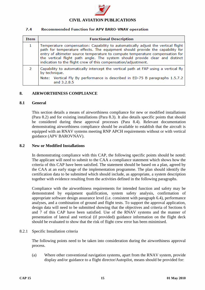
CCIIVVIILL AAVVIIAATTIIOONN PPUUBBLLIICCAATTIIOONNSS
CAP 15 15 01 May 2010
8. AIRWORTHINESS COMPLIANCE 8.1 General
This section details a means of airworthiness compliance for new or modified installations (Para 8.2) and for existing installations (Para 8.3). It also details specific points that should be considered during these approval processes (Para 8.4). Relevant documentation demonstrating airworthiness compliance should be available to establish that the aircraft is equipped with an RNAV systems meeting RNP APCH requirements without or with vertical guidance (APV BAROVNAV).
8.2 New or Modified Installations
In demonstrating compliance with this CAP, the following specific points should be noted: The applicant will need to submit to the CAA a compliance statement which shows how the criteria of this CAP have been satisfied. The statement should be based on a plan, agreed by the CAA at an early stage of the implementation programme. The plan should identify the certification data to be submitted which should include, as appropriate, a system description together with evidence resulting from the activities defined in the following paragraphs. Compliance with the airworthiness requirements for intended function and safety may be demonstrated by equipment qualification, system safety analysis, confirmation of appropriate software design assurance level (i.e. consistent with paragraph 6.4), performance analyses, and a combination of ground and flight tests. To support the approval application, design data will need to be submitted showing that the objectives and criteria of Sections 6 and 7 of this CAP have been satisfied. Use of the RNAV systems and the manner of presentation of lateral and vertical (if provided) guidance information on the flight deck should be evaluated to show that the risk of flight crew error has been minimised.
8.2.1 Specific Installation criteria
The following points need to be taken into consideration during the airworthiness approval process.
(a) Where other conventional navigation systems, apart from the RNAV system, provide
display and/or guidance to a flight director/Autopilot, means should be provided for:

CCIIVVIILL AAVVIIAATTIIOONN PPUUBBLLIICCAATTIIOONNSS
CAP 15 16 01 May 2010
- a navigation system source selector as the only means of selection;
- Clear annunciation of the selected navigation system on or near the navigation display;
- Display of guidance information appropriate to the selected navigation system;
- Delivery of guidance information to a flight director/autopilot appropriate to
the selected navigation system.
(b) Annunciation for flight director, autopilot and selected navigation system should be consistent, and compatible with the original design philosophy of the cockpit.
(c) Loss of navigation capability should be indicated to the flight crew.
(d) Equipment failure scenarios involving conventional navigation systems and the
RNAV system(s) should be evaluated to demonstrate that:
- Adequate alternative means of navigation are available following failure of the RNAV system; and
- Reversionary switching arrangements, e.g. VOR/GPS#2 on HSI#1, do not lead to misleading or unsafe display configurations.
The evaluation should consider also the probability of failures within the switching arrangements.
(e) If barometric altitude input is used by the RNAV system (e.g. Baro aiding for RAIM
function), loss of altitude information should be indicated by the RNAV system. (f) The coupling arrangements between the RNAV system and the flight
director/automatic pilot should be evaluated to show compatibility and to demonstrate that operating modes, including RNAV system failures modes, are clearly and unambiguously indicated to the flight crew.
(g) The use of the RNAV system and the manner of presentation of lateral and vertical
(if provided) guidance information on the flight deck should be evaluated to show that the risk of flight crew error has been minimised. The crew should be aware, at any time, of the system used for navigation.
(h) The installation configuration features provided by the RNAV system which affect
airworthiness approval or operational criteria, such as: external CDI selection; external CDI calibration; entering of GPS antenna height above ground; serial Input/Output port configuration; reference datum, should not be selectable by the pilot. Instructions on how to configure the RNAV system for the particular installation should be listed in the appropriate manual.
(i) Controls, displays, operating characteristics and pilot interface to RNAV system
should be assessed in relation to flight crew workload, particularly in the approach environment. Essential design considerations include:
CCIIVVIILL AAVVIIAATTIIOONN PPUUBBLLIICCAATTIIOONNSS
CAP 15 17 01 May 2010
- Minimising reliance on flight crew memory for any system operating procedure or task. Developing a clear and unambiguous display of system modes/sub-modes and navigational data with emphasis on enhanced situational awareness requirements for any automatic mode changes, if provided.
- Use of context sensitive helps capability and error messages (for example,
invalid inputs or invalid data entry messages should provide a simple means to determine how to enter “valid” data).
- Placing particular emphasis on the number of steps and minimising the time required to accomplish flight plan modifications to accommodate ATS clearances, holding procedures, runway and instrument approach changes, missed approaches and diversions to alternate destinations.
- Minimising the number of nuisance alerts so the flight crew will recognise
and react appropriately when required. 8.3 Existing Installations
Aircraft that are approved for RNP AR APCH operations are considered compliant with this CAP.
An existing statement in the AFM that indicates the aircraft is approved:
- To perform RNP 0.3 GNSS approaches or, for
- instrument approaches including a specification of RNP GNSS capability that meets
RNP 0.3 is considered acceptable for lateral performance.
If this is not the case, the applicant will need to submit to the CAA a compliance statement which shows how the criteria of this CAP have been satisfied for existing installations. Compliance may be established by inspection of the installed system to confirm the availability of required features and functionality. The performance and integrity criteria of Sections 6 and 7 may be confirmed by reference to statements in the Aircraft Flight Manual or to other applicable approvals and supporting certification data. In the absence of such evidence, supplementary analyses and/or tests may be required.
To avoid unnecessary regulatory activity, the determination of eligibility for existing systems should consider acceptance of manufacturer documentation. In this specific case, an AFM amendment is recommended to reflect the RNP APCH aircraft capability. The addition of this aircraft capability in the AFM without any technical modification applied to the aircraft could be considered as a Minor change by the CAA.
8.4 Specific Installation assessment 8.4.1 Lateral and vertical Fly-By transition mechanism
The applicant should demonstrate that the turn indication during lateral flyby transitions is accurate enough to keep the aircraft within the theoretical transition area as described in ED75 B paragraph 3.2.5.4.
CCIIVVIILL AAVVIIAATTIIOONN PPUUBBLLIICCAATTIIOONNSS
CAP 15 18 01 May 2010
Lateral Fly-by transition assessment should be evaluated in manual and in autopilot mode. If the equipment provides positive course guidance through the turn (during the fly-by transition), then no specific flight test is required.
The applicant should demonstrate that the vertical indication during vertical flyby transitions is accurate enough to keep the aircraft within the profile described in ED75 B paragraph 3.2.8.5. Vertical Fly-by transition assessment should be evaluated in manual and in autopilot mode. It is recalled that momentary deviation below the published minimum procedure altitude at the FAP is acceptable provided the deviation is limited to no more than 50 feet assuming no VNAV equipment error.
8.4.2 Enhanced navigation displays
It is recognised that enhanced navigation display (such as IFR approved electronic moving map or enhanced EHSI) improves crew lateral situational awareness and navigation monitoring. It is strongly recommended that the RNAV installation incorporates an IFR approved moving map display. This may be a standalone display or may be integrated within the aircraft electronic display system or directly integrated within the GNSS standalone receiver. For certain cases an enhanced navigation display is required (see Para 7.1 Item 1).
The graphical map display should incorporate at least the active flight plan, map ranges consistent with the flight operation, available navigation aids, and airports. Design and installation of enhanced navigation display should be approved during the approval process; in particular the evaluation of the man-machine interface (colour, symbol, cluttering aspect, display location, display size, etc.).
Enhanced navigational display is considered an essential function for the crew to verify the approach procedure loaded from the navigational database. This display is also a key element for the navigation crew monitoring (e.g. flight plan progress).
8.4.3 Intermixing of equipment
Simultaneous use of RNAV systems with different crew interfaces can be very confusing and can lead to problems when they have conflicting methods of operation and conflicting display formats. For approach operations, simultaneous use of RNAV equipment which is not identical or compatible is not permitted.
9. AIRCRAFT FLIGHT MANUAL/PILOT OPERATING HANDBOOK
For new or modified aircraft, the Aircraft Flight Manual (AFM) or the Pilot’s Operating Handbook (POH), whichever is applicable, should provide at least the following information:
(a) A statement which identifies the equipment and aircraft build or modification
standard certificated for RNP APCH operation with or without vertical guidance (APV BAROVNAV). This may include a very brief description of the RNAV/GNSS system, including the RNAV/GNSS airborne equipment software version, CDI/HSI equipment and installation and a statement that it is suitable for RNAV operations. A brief introduction to the RNAV(GNSS) approach concept using ICAO RNP APCH terminology may also be included.

CCIIVVIILL AAVVIIAATTIIOONN PPUUBBLLIICCAATTIIOONNSS
CAP 15 19 01 May 2010
(b) Appropriate amendments or supplements to cover RNP APCH approach operations in the following sections:
• Limitations – including use of VNAV, FD and AP; currency of navigation database;
crew verification of navigation data; availability of RAIM or equivalent function; restrictions on use of GNSS for conventional Non Precision Approaches.
• Normal Procedures • Abnormal Procedures – including actions in response to a Loss of Integrity (e.g.
‘RAIM Position Warning’, (or equivalent) message or a ‘RAIM not available’, (or equivalent) message).
Note: This limited set assumes that a detailed description of the installed system and
related operating instructions and procedures are available in other approved operational or training manuals.
10. RNP APCH OPERATIONAL CRITERIA
This section describes acceptable operational criteria for approach operations, subject to the limitations given below. The operational criteria assume that the corresponding installation/airworthiness approval has been granted by the CAA. Operational criteria apply to the use of the RNAV system for RNP APCH operations on any aircraft operated under IFR. Operations of the RNAV system should be in accordance with the AFM or AFM supplement. The operational procedures to be addressed by the operator are detailed in Appendix 4. The (Master) Minimum Equipment List (MMEL/MEL) should be amended to identify the minimum equipment necessary to satisfy operations using the RNAV system. The operator should determine the operational characteristics of the procedure to be flown. It is recommended that the process described in paragraph 10.3 and Appendix 2 of this CAP should be followed to validate its operational use by the crew. Depending on the aircraft capability and the approach procedure, RNP APCH procedures may be conducted with lateral (LNAV), lateral/vertical (LNAV/VNAV) or equivalent mode engaged, and coupling with either a flight director or autopilot. Prior to the operation, the operator needs to be authorised by the CAA for such operations.
10.1 Flight Operations Documentation
The relevant parts and sections of the Operations Manual (e.g., Aircraft Operations Manual, check lists, training of crew) should be revised to take account of the operating procedures detailed in this section and, in particular those in Appendix 4. The operator should make timely amendments to the Operations Manual to reflect relevant RNP APCH procedure without or with vertical guidance (APV BAROVNAV) and database checking strategies. Manuals and check lists need to be submitted for review by the responsible authority as part of the authorisation process.

CCIIVVIILL AAVVIIAATTIIOONN PPUUBBLLIICCAATTIIOONNSS
CAP 15 20 01 May 2010
The aircraft operator should propose an amendment to the Minimum Equipment List (MEL) appropriate to RNP APCH operations.
10.2 Flight Crew Training
Each pilot should receive appropriate training, briefings and guidance material in order to safely conduct RNP APCH operations without or with vertical guidance (APV BAROVNAV). This material and training should cover both normal and abnormal procedures. Standard training and checking, such as recurrent aeroplane/STD training and proficiency checks, should include RNP APCH procedures. Based on this, the operator should determine what constitutes a qualified crew.
The operator should ensure that during line operations each pilot can perform assigned duties reliably and expeditiously for each procedure to be flown in:
(a) normal operations and (b) abnormal operations
The operator should ensure that altimeter settings procedures and cold temperature limitations during APV BAROVNAV operation are respected.
(a) Altimeter setting
Flight Crews should take precautions to switch altimeter settings at appropriate times or locations and request a current altimeter setting if the reported setting is not recent, particularly at times when pressure is reported or is expected to be rapidly decreasing. Remote (regional) altimeter settings are not allowed.
Note: The operational crosscheck between altimeter readout and charted altitude
values at FAF or other profile fixes does not protect against altimeter setting errors.
(b) Cold Temperature
When cold weather temperatures exist, the pilot should check the chart for the instrument approach procedure to determine the limiting temperature for the use of BAROVNAV capability. If the airborne system contains a temperature compensation capability, manufacturer instructions should be followed for use of the BAROVNAV function, and the operational use of the temperature compensation function must be authorised by the Air Navigation Service Provider.
A training programme should be structured to provide sufficient theoretical and practical training. An example of training syllabus is described in Appendix 5.
10.3 Aerodrome competence and Operator verification
Before planning a flight to an aerodrome (destination or alternate) with the intent to use an RNAV procedure contained in the Navigation Database, the operator should determine the operational characteristics of the procedure in accordance with ANTR OPS 1.975 or the applicable operational regulations. Further details are provided in Appendix 2.
CCIIVVIILL AAVVIIAATTIIOONN PPUUBBLLIICCAATTIIOONNSS
CAP 15 21 01 May 2010
Based on this assessment, the appropriate information should be given to the crew. If the aerodrome access requires a specific competence, the designated crew shall have a validated competence.
Note: This CAP addresses only RNP APCH procedures which are designed with straight
segment (e.g. T or Y approach). It is therefore anticipated that in most cases no specific competence should be required to fly such approach procedure.
10.4 Navigation Database Management 10.4.1 Operator involved in commercial air operations
Refer to ANTR-OPS 1.873 for the management of navigation database. 10.4.2 Operator not involved in commercial air operations
The operators should not use a navigation database for RNP APCH operations unless the navigation database supplier holds a Type 2 Letter of Acceptance (LoA) or equivalent.
An EASA Type 2 LoA is issued by EASA in accordance with EASA OPINION Nr. 01/2005 on “The Acceptance of Navigation Database Suppliers” dated 14 Jan 05. The FAA issues a Type 2 LoA in accordance with AC 20153, while Transport Canada (TCCA) issues an Acknowledgement Letter of an Aeronautical Data Process using the same basis. Both the FAA LoA and the TCCA Acknowledgement Letter are seen to be equivalent to the EASA LoA. EUROCAE/RTCA document ED76/ DO200A Standards for Processing Aeronautical Data contains guidance relating to the processes that the supplier may follow. The LoA demonstrates compliance with this standard.
10.4.2.1 Non-approved Suppliers
If the operator’s supplier does not hold a Type 2 LoA or equivalent, the operator should not use the electronic navigation data products unless the Authority has approved the operator’s procedures for ensuring that the process applied and the delivered products have met equivalent standards of integrity. An acceptable methodology is described in Appendix 3 of this CAP.
10.4.2.3 Quality Monitoring
The operator should continue to monitor both the process and the products in accordance with the quality system required by the applicable operational regulations.
10.4.2.4 Data Distribution
The operator should implement procedures that ensure timely distribution and insertion of current and unaltered electronic navigation data to all aircraft that require it.
10.5 Reportable Events
A reportable event is one that adversely affects the safety of the operation and may be caused by actions/events external to the operation of the aircraft navigation system. The operator should have in place a system for investigating such an event to determine if it is

CCIIVVIILL AAVVIIAATTIIOONN PPUUBBLLIICCAATTIIOONNSS
CAP 15 22 01 May 2010
due to an improperly coded procedure, or a navigation data base error. Responsibility for initiating corrective action rests with the operator. For those operators for whom approval is granted under ANTR OPS 1, the following events should be the subject of Occurrence Reports (see ANTR-OPS 1.420): Technical defects and the exceeding of technical limitations, including:
(a) Significant navigation errors attributed to incorrect data or a data base coding error. (b) Unexpected deviations in lateral/vertical flight path not caused by pilot input or
erroneous operation of equipment. (c) Significant misleading information without a failure warning. (d) Total loss or multiple navigation equipment failure. (e) Loss of integrity (e.g. RAIM) function whereas integrity was predicted to be
available during the pre-flight planning. 11. APPLICATION & APPROVAL PROCESS 11.1 Pre-application Meeting
Each individual operator should schedule a pre-application meeting with the CAA. The intent of this meeting is to discuss airworthiness and operational requirements for approval to conduct RNP APCH operations in European airspace, including:
(a) the contents of the operator’s application, (b) CAA’s review and evaluation of the application, (c) limitations (if any) on the approval, and (d) conditions under which the operational approval may be cancelled by the CAA. (e) any other operational or airspace requirements that may be established by European
or other authorities for the airspace involved. 11.2 Application An application for the approval for RNP APCH approval must be made by the operator,
using Form ALD/OPS/F062. The appropriate charges must accompany the application, unless specifically exempted.
11.3 Supporting Documents
The documents listed below in respect of each aircraft, should normally accompany the application for grant of approval for RNP APCH. (a) The copies of Supplemental Type Certificates (STC) for each type of RNAV
equipment fitted on each aircraft:

CCIIVVIILL AAVVIIAATTIIOONN PPUUBBLLIICCAATTIIOONNSS
CAP 15 23 01 May 2010
(1) minimum level of integrity and availability; and (2) functional criteria.
(b) Maintenance programme/approved maintenance schedule for each aircraft.
(i.e. transit, periodical inspection and test).
(c) Equipment lists (MMEL and MEL) that identify the minimum equipment necessary for RNP APCH operations in respect of each aircraft.
(d) Part of the Aircraft Flight Manuals (AFMs) for each aircraft, that specifies the
following:
(1) the basis for certification together with any RNAV system limitations; and
(2) the appropriate RNAV system operating and emergency procedures applicable to the equipment installed:
(i) Normal procedure for operating the equipment; (ii) Equipment operating limitations; and (iii) Emergency operating procedures.
(e) Training programmes in respect of the RNAV equipment installed in each aircraft
for: (1) Maintenance personnel; and
(2) Flight crew. All operators must submit training syllabi and other
appropriate material to show that the operational practices and procedures and training items related to RNP APCH operations are incorporated in training programmes where applicable (e.g. initial, upgrade, recurrent).
(f) Operations Manual amendment indicating the procedures applicable. AOC holders
and private operators must revise their operations manual and checklists to include information/guidance on standard operating procedures. Appropriate manuals should include navigation operating instructions and contingency procedures where specified. Manuals and checklists must be submitted for review as part of the application process. Practices and procedures in the following areas must be standardised and include flight planning; pre-flight procedures at the aircraft for each flight; in-flight procedures; in-flight contingency procedures and flight crew qualification requirements.
11.4 Approval
Approval to conduct RNP APCH will be granted by inclusion in the Operations Specifications of the AOC holder. For private category aircraft a Certificate will be issued.

CCIIVVIILL AAVVIIAATTIIOONN PPUUBBLLIICCAATTIIOONNSS
CAP 15 24 01 May 2010
11.5 Cancellation of RNP APCH Approval
Operators are reminded that after a RNP APCH approval is issued, the CAA conducts regular surveillance on all operations using performance based navigation. When appropriate, the CAA may consider any navigation error reports in determining remedial action. Repeated navigation error occurrences, attributed to a specific piece of navigation equipment, may result in cancellation of the approval. Information that indicates the potential for repeated errors may require a modification of an operator’s training programme. Information that attributes multiple errors to a particular pilot crew may necessitate remedial training.

CCIIVVIILL AAVVIIAATTIIOONN PPUUBBLLIICCAATTIIOONNSS
CAP 15 APP 1-1 01 May 2010
APPENDIX 1
DEFINITIONS The following are definitions of key terms used throughout this CAP. Aircraft Based Augmentation System (ABAS): An augmentation system that augments and/or integrates the information obtained from the other GNSS elements with information available on board the aircraft. APV (Approach Procedure with Vertical guidance): An instrument approach procedure which utilises lateral and vertical guidance but does not meet the requirements established for precision approach and landing operations. Area navigation (RNAV): A method of navigation which permits aircraft operation on any desired flight path within the coverage of station referenced navigation aids or within the limits of the capability of self contained aids, or a combination of these. Accuracy: The degree of conformance between the estimated, measured, or desired position and/or the velocity of a platform at a given time, and its true position or velocity. Navigation performance accuracy is usually presented as a statistical measure of system error and is specified as predictable, repeatable and relative. ASE (Altimetry System error): Altimetry error refers to the electrical output and includes all errors attributable to the aircraft altimetry installation including position effects resulting from normal aircraft flight attitudes. Availability: An indication of the ability of the system to provide usable service within the specified coverage area and is defined as the portion of time during which the system is to be used for navigation during which reliable navigation information is presented to the crew, automatic pilot, or other system managing the flight of the aircraft. BAROVNAV (Barometric Vertical Navigation) is a navigation system that presents to the pilot a computed vertical guidance based on barometric altitude. Basic GNSS operation: Operation that are based on GNSS Aircraft Based Augmentation System (ABAS). An ABAS system is typically a GNSS receiver with fault detection compliant to E/TSO C 129a, E/TSOC145() or E/TSOC146(). Continuity of Function: The capability of the total system (comprising all elements necessary to maintain aircraft position within the defined airspace) to perform its function without non-scheduled interruptions during the intended operation. DA(H): Decision altitude (DA) or Decision height (DH). A specified altitude or height in the precision approach or approach with vertical guidance at which a missed approach must be initiated if the required visual reference to continue the approach has not been established. FAP: Final Approach Point. Fault Detection and Exclusion (FDE): FDE is a receiver processing scheme that autonomously provides integrity monitoring for the position solution, using redundant range measurements. The

CCIIVVIILL AAVVIIAATTIIOONN PPUUBBLLIICCAATTIIOONNSS
CAP 15 APP 1-2 01 May 2010
FDE consist of two distinct parts: fault detection and fault exclusion. The fault detection part detects the presence of an unacceptably large position error for a given mode of flight. Upon the detection, fault exclusion follows and excludes the source of the unacceptably large position error, thereby allowing navigation to return to normal performance without an interruption in service. GNSS standalone receiver: A GNSS system incorporating the GNSS sensor, the navigation capability and the navigation data base. GNSS sensor: A GNSS system incorporating only the GNSS receiving and positioning part. It doesn’t incorporate the navigation capability and the navigation data base. HCE (Horizontal Coupling Error): The vertical error component of an along track positioning error Integrity: The ability of a system to provide timely warnings to users when the system should not be used for navigation. MDA(H): Minimum descent altitude (MDA) or minimum descent height (MDH). A specified altitude or height in a non-precision approach or circling approach, below which, descent should not be made without the required visual reference. NSE (Navigation System Error): The difference between true position and estimated position OCA/H: In a precision approach procedure (or APV), the OCA/H is defined as the lowest altitude/height at which a missed approach must be initiated to ensure compliance with the appropriate obstacle clearance design criteria. On board Monitoring and Alerting function: This function is the main element which determines if the navigation system complies with the necessary safety level associated to a RNP application; it relates to both lateral and longitudinal navigation performance. Onboard performance monitoring and alerting allows the flight crew to detect that the RNAV system is not achieving the navigation performance required. Onboard performance monitoring and alerting is concerned with the monitoring of all type of errors which may affect the aircraft ability to follow the desired flight path. TCH: Threshold Crossing Height. The height of the Glide Path above the threshold. TSE (Total System Error): The difference between true position and desired position. This error is equal to the root sum square (RSS) of the Flight Technical Error (FTE), Path Definition Error (PDE), and Navigation System Error (NSE). PDE (Path Definition Error): The difference between the defined path and the desired path. Receiver Autonomous Integrity Monitoring (RAIM): A technique whereby a GNSS receiver/processor determines the integrity of the GNSS navigation signals using only GPS signals or GPS signals augmented with altitude. This determination is achieved by a consistency check among redundant pseudorange measurements. At least one satellite in addition to those required for navigation should be in view for the receiver to perform the RAIM function.

CCIIVVIILL AAVVIIAATTIIOONN PPUUBBLLIICCAATTIIOONNSS
CAP 15 APP 1-3 01 May 2010
RNAV System: A navigation system which permits aircraft operation on any desired flight path within the coverage of station referenced navigation aids or within the limits of the capability of self contained aids, or a combination of these. A RNAV system may be included as part of a Flight Management System (FMS). RNAV(GNSS) approach: A GNSS RNAV approach promulgated by a State and designed in accordance with PANSOPS Criteria Doc 8168, Volume II, Part III, Section 1, Chapter 2 and Section 3, Chapter 3 (Basic GNSS). Such approach should be flown by using an airborne RNAV system approved for RNP APCH operations. SBAS: Satellite Based Augmentation System. SBAS augments core satellite constellation by providing ranging, integrity and correction information via geostationary satellites. This system comprises a network of ground reference stations that observe satellites signals, and master stations that process observed data and generate SBAS messages for uplink to the geostationary satellites, which broadcast the SBAS message to the users. RNP APCH: RNP AProaCH. A RNP approach defined in the ICAO Performance Based Manual (PBN) manual. An approach equivalent to the RNAV (GNSS) one. TSOC129()/ETSOC129a GPS Class A equipment: Equipment incorporating both the GNSS sensor and navigation capability. This equipment incorporates RAIM as defined by TSO/ETSOC129(). TSOC129()/ETSOC129 a GPS Class B and C equipment: GNSS sensor providing GNSS data (position, integrity,..) to an integrated navigation system (e.g. FMS). TSOC146() Class GAMMA: This functional class corresponds to equipment consisting of both the GNSS/SBAS position sensor and a navigation function, so that the equipment provides path deviations relative to a selected path. The equipment provides the navigation function required of a standalone navigation system. This equipment also provides integrity in the absence of SBAS signal through the use of FDE. In addition, this class of equipment requires a data base, display outputs and pilot controls. TSOC145() class BETA: Equipment consisting of a GNSS/SBAS sensor that determines position (with integrity) and provides position and integrity to an integrated navigation system (e.g. flight management system, multi-sensory navigation system). This equipment also provides integrity in the absence of the SBAS signal through the use of fault detection and exclusion (FDE). TSOC146() or TSOC145() Operational Class 1: This operational class supports oceanic and domestic enroute, terminal and non precision approach, and departure operation. TSOC146() or TSOC145() Operational Class 2: This operational class supports oceanic and domestic enroute, terminal and non precision approach, LNAV/VNAV and departure operation. TSOC146() or TSOC145 ( ) Operational Class 3: This operational class supports oceanic and domestic enroute, terminal and non precision approach, LNAV/VNAV, LPV and departure operation. “T” approach: T approach is defined in ICAO document 8168 and in RTCA/EUROCAE DO 201A/ED 77. “T” approach is composed of two initial approach segments perpendicular to the intermediate approach segment.

CCIIVVIILL AAVVIIAATTIIOONN PPUUBBLLIICCAATTIIOONNSS
CAP 15 APP 1-4 01 May 2010
Vertical Navigation: A method of navigation which permits aircraft operation on a vertical flight profile using altimetry sources, external flight path references, or a combination of these. VPA (Vertical Path Angle): Angle of the published final approach descent. VTF: Vector To Final. VSR: Reference Stall Speed. “Y” approach: Y approach is defined in ICAO document 8168 and in RTCA/EUROCAE DO 201A/ED 77. “Y” approach is derived from the “T” approach but the initial segments are establishing at 70° to the intermediate segment rather than 90°.

CCIIVVIILL AAVVIIAATTIIOONN PPUUBBLLIICCAATTIIOONNSS
CAP 15 APP 2-1 01 May 2010
APPENDIX 2
OPERATIONAL CHARACTERISTICS OF THE PROCEDURE AND OPERATIONAL USE
The operator should show evidence that consideration has been given to the evaluation of any new or modified RNP APCH procedures. RNP APCH procedure should be designed using straight segments; the operator should check that the selected procedure fulfils this requirement. Particular attention should be paid to procedures:
- In mountainous environments,
- within the proximity of well known obstacles, - that may require adequate knowledge for the aerodrome access or aerodrome
competence qualification, as specified in ANTR-OPS 1.975 or the applicable operational requirements.
Competence may be required specifically for this RNAV procedure or the procedure may be published for an aerodrome already listed as requiring an aerodrome competence. This may be aircraft type related and subject to periodic revalidation.
- In the absence of radar coverage,
- When missed approach trajectory involve turns, especially at low altitudes, - Subject to a declared exemption to the procedure design rules specified by the ICAO
PANS OPS, - Every other case considered necessary to be evaluated by the operator.
The operator may develop an internal process (e.g. filtering methods or tools covering the AIP review) to detect RNP APCH procedure(s) showing one or more of the above listed characteristics.
The operational evaluation of a RNP APCH procedure showing evidence of the abovementioned operational characteristics may include, at operator discretion, an approach conducted with the aircraft in VMC or the use of a full flight simulator (FFS) in order to evaluate if the procedure is correctly executed by the RNAV system and flyable with the aircraft type.

CCIIVVIILL AAVVIIAATTIIOONN PPUUBBLLIICCAATTIIOONNSS
CAP 15 APP 2-2 01 May 2010
This Page Intentionally Left Blank

CCIIVVIILL AAVVIIAATTIIOONN PPUUBBLLIICCAATTIIOONNSS
CAP 15 APP 3-1 01 May 2010
APPENDIX 3
ALTERNATE NAVIGATION DATABASE INTEGRITY CHECK
If operator’s navigation data base supplier has no Type 2 LOA, the operator should develop and describe a method to demonstrate an acceptable level of integrity of the navigation data base content used by the RNAV system on board the aircraft. The operator should implement navigation data base integrity checks for all RNP APCH procedures they wish to operate, using manual verification procedures or appropriate software tools, at each AIRAC Cycle. The objective of this integrity check is to identify any significant discrepancies between the published charts/procedures and the navigation database content. Integrity checks may be conducted by a designated third party, under the operator responsibility.
1 Elements to be verified
At least the following elements of an RNP APCH should be verified:
- Coordinates/location verification of IAF, IF, FAF, MAPt, and other waypoints between IAF and MAPt (if any)
- Tracks between these waypoints - Distance between these waypoints - Vertical path angle (for APV BAROVNAV operation)
2 Means to verify those elements 2.1 The Operator verification process
The operator should, at the very least, verify the information listed in paragraph 1 of this Appendix, by comparison with the official published data. As the data may evolve at each AIRAC Cycle, this verification should be done at every AIRAC cycle using comparison with source documents or a reference data base (gold standard). The operator should describe the method used to verify the navigation data base integrity which can be based on a:
(a) manual method, with or without software support, whereby the airborne data base is
compared with the original published data, or
(b) recurrent method with a reference database, whereby any changes identified between the latest data base and the reference data base are checked against the original

CCIIVVIILL AAVVIIAATTIIOONN PPUUBBLLIICCAATTIIOONNSS
CAP 15 APP 3-2 01 May 2010
published data. Once the latest data base has been verified, it becomes the reference data base for the next AIRAC cycle.
The recurrent method relies on the integrity of the initial data base, and requires that the check of every RNP APCH procedure has been properly conducted and validated at the very first time. It also relies on the assumption that every change in the data base is properly identified and checked. It is recommended that software tools are used to compare the contents of one (N) AIRAC cycle data base with the contents of the previous (N1) AIRAC cycle data base.
Whatever the method, data to be checked must come from the final source to be loaded on the aircraft.
2.2 The means to enable this verification
In many cases, the RNAV system and an enhanced navigation display are necessary to access the data (on the aircraft or on a flight simulator). An RNAV system comparable to the one installed on the aircraft (i.e. using the same algorithms) may also be used, as well as appropriate simulation software tools. The RNAV system manufacturer should be consulted on the adequacy of specific software for this purpose. Data may also be acquired through a tool able of unpacking the data encoded on the files (e.g. de-compactor) developed by the RNAV system manufacturer. Whatever software tool is used, it should be validated for its intended use by the operator.
3 Feed back and reporting errors found
In case of errors found, the operator should take appropriate actions. In particular, significant errors (i.e. those that would affect the flight path of the aircraft) should be reported to the database supplier and the competent authority and affected procedures should be prohibited by a company instruction or NOTAM.
Note: Integrity checks could be conducted for several operators by a same designated third
party. In this case, it is strongly recommended that any problem recorded by this third party be reported to all its client operators.

CCIIVVIILL AAVVIIAATTIIOONN PPUUBBLLIICCAATTIIOONNSS
CAP 15 APP 4-1 01 May 2010
APPENDIX 4
OPERATIONAL PROCEDURES
This Appendix should be used by the operator to amend the relevant parts and sections of the Operations Manual as described in 10.1 to support these types of operations.
1 Normal Procedures 1.1 Pre-flight Planning
Operators and flight crew intending to conduct operations on RNP APCH procedures must file the appropriate flight plan suffixes. The onboard navigation data must be current and must include the appropriate procedures. In addition to the normal pre-flight planning, the following additional checks must be carried out:
(a) The instrument approach chart should clearly identify the RNP APCH operation as
RNAV(GNSS) or equivalent (e.g.: RNAV(GNSS) RWY 27,…). The operator should determine in accordance with the promulgated OCA(H) and the operational requirement (e.g. ANTR-OPS 1.430) the Minimum Descent Altitude/Height (MDA(H)) for LNAV approaches or the Decision Altitude/Height (DA(H)) for APV BAROVNAV operation.
(b) Flight crew must ensure that RNP APCH procedures which may be used for the
intended flight (including alternates aerodromes) are selectable from a valid navigation data base (current AIRAC cycle) and are not prohibited by a company instruction or NOTAM. Flight crew could check approach procedures (including alternate aerodromes) as extracted by the system (e.g. CDU flight plan page) or presented graphically on the moving map, in order to confirm the correct loading and the reasonableness of the procedure content. The vertical path of the APV BAROVNAV procedure could be checked as extracted from the navigation data base on the RNAV Man Machine Interface (e.g. MCDU).
If above verification is not satisfactory, the flight crew should not use the procedure, and not consider this approach(es) during the selection of aerodromes for the intended flight.
(c) Flight crew should ensure sufficient means are available to navigate and land at the
destination or at an alternate aerodrome in the case of loss of RNP APCH airborne capability.
In particular, the pilot should check that:
- A non-RNP APCH procedure is available at the alternate, where a destination
alternate is required;

CCIIVVIILL AAVVIIAATTIIOONN PPUUBBLLIICCAATTIIOONNSS
CAP 15 APP 4-2 01 May 2010
- At least one non-RNP APCH procedure is available at the destination aerodrome, where a destination alternate is not required
(d) Operators and flight crews must take account of any NOTAMs or operator briefing
material that could adversely affect the aircraft system operation, or the availability or suitability of the procedures at the airport of landing, or any alternate airport.
(e) If the missed approach procedures are based on conventional means (VOR, NDB),
the appropriate airborne equipment required to fly this procedure must be installed in the aircraft and must be operational. The associated ground based navaids must also be operational.
If the missed approach procedure is based on RNAV (no conventional or dead reckoning missed approach available), the appropriate airborne equipment required to fly this procedure must be available and serviceable on board the aircraft.
(f) For those GNSS systems relying on RAIM, its availability 15 min before Estimated
Time of Arrival (ETA) until 15 min after ETA should be verified during the pre-flight planning. In the event of a predicted continuous loss of fault detection of more than five (5) minutes, the flight planning should be revised (e.g. delaying the departure or planning a different approach procedure).
Note 1: For certain systems, prediction is not systematic but is only required
in specific cases and shall be detailed in the relevant section of the AFM
Note 2: RAIM availability prediction services may be provided to users by the
air navigation service provider (ANSP), an avionics manufacturer or other entities.
(g) Any MEL restriction should be observed
1.2 Prior to Commencing the Procedure
In addition to normal procedure prior to commencing the approach (before the IAF and in compatibility with crew workload), the flight crew must verify the correctness of the loaded procedure by comparison with the appropriate approach charts. This check must include:
(a) The waypoint sequence.
(b) Reasonableness of the tracks and distances of the approach legs, and the accuracy of
the inbound course and mileage of the final approach segment.
Note: As a minimum, this check could be a simple inspection of a suitable map display.
(c) The vertical path angle.
For multi-sensor systems, the crew must verify during the approach that GNSS sensor is used for position computation.
CCIIVVIILL AAVVIIAATTIIOONN PPUUBBLLIICCAATTIIOONNSS
CAP 15 APP 4-3 01 May 2010
For an RNAV system with ABAS requiring barometric corrected altitude, the current airport barometric altimeter setting, should be input at the appropriate time, consistent with the performance of the flight operation. For those GNSS systems relying on RAIM and necessitating a check of its availability for RNP APCH, the flight crew should perform a new RAIM availability check if ETA is more than 15 minutes different from the ETA used during the pre-flight planning. This check is also performed automatically for ETSO/TSOC129a Class A1 receiver, 2 NM before the FAF.
Note: Systems providing RNP alerts that reflect loss of GNSS integrity are considered
acceptable and no flight crew RAIM availability check is required.
For APV BAROVNAV operation, the crew must confirm the correct altimeter setting. The procedure must only be flown with:
(a) a current local altimeter setting source available; and
(b) the QNH/QFE, as appropriate, set on the aircraft’s altimeters.
Procedures using a remote (regional) altimeter setting source cannot support APV BAROVNAV approach.
For APV BAROVNAV operation, pilots are responsible for any necessary cold temperature compensations to all published minimum altitudes/heights. This includes:
(a) the altitudes/heights for the initial and intermediate segment(s);
(b) the DA/H; and
(c) subsequent missed approach altitudes/heights.
APV BAROVNAV procedures are not permitted when the aerodrome temperature is below the promulgated minimum aerodrome temperature for the procedure, unless the RNAV system is equipped with approved cold temperature compensation for the final approach.
ATC tactical interventions in the terminal area may include radar headings, ‘direct to’ clearances which bypass the initial legs of an approach, interceptions of an initial or intermediate segments of an approach or the insertion of additional waypoints loaded from the data base. In complying with ATC instructions, the flight crew should be aware of the implications for the RNAV system.
(a) The manual entry of coordinates into the RNAV system by the flight crew for
operation within the terminal area is not permitted.
(b) ‘Direct to’ clearances may be accepted to the Intermediate Fix (IF) provided that the resulting track change at the IF does not exceed 45°.
Note: Direct to clearance to FAF is not acceptable. Modifying the procedure to intercept
the final approach course prior to the FAF is acceptable for radar vectored arrivals or at other times with ATC approval.

CCIIVVIILL AAVVIIAATTIIOONN PPUUBBLLIICCAATTIIOONNSS
CAP 15 APP 4-4 01 May 2010
The lateral and vertical (for APV BAROVNAV operation) definition of the flight path between the FAF and the Missed Approach Point (MAPt) must not be revised by the flight crew under any circumstances.
1.3 During the Procedure
The final approach trajectory must be intercepted no later than the FAF in order for the aircraft to be correctly established on the final approach course before starting the descent (to ensure terrain and obstacle clearance).
The crew must check the RNAV approach mode annunciator (or equivalent) is properly indicating approach mode integrity 2 NM before the FAF.
Note: This will not apply for certain RNAV system (e.g. aircraft already approved with
demonstrated RNP capability). For such systems, other means are available including electronic map displays, flight guidance mode indications, etc., which clearly indicate to the crew that the approach mode is activated.
For APV BAROVNAV operation, the crew should check that the two altimeters provide equivalent altitude (difference of 100 feet max) at or before FAF. This check must be made after the crew has set the correct altimeter setting.
The crew should also check the consistency between the VNAV guidance and the primary altimeters indications commensurate with pilot workload (e.g. after the aircraft is established on the vertical path).
During the descent, crew should check that the vertical speed is consistent with the VNAV angle to be flown.
The appropriate displays must be selected so that the following information can be monitored:
(a) The RNAV computed desired path (DTK), and
(b) Aircraft position relative to the lateral path (Cross Track Deviation) for FTE
monitoring
(c) Aircraft position relative to the vertical path (for APV BAROVNAV operation)
The crew should respect all published altitude and speed constraints.
The procedure must be discontinued:
(a) If RNAV failure is annunciated (e.g. warning flag), (b) If the NSE alarm is triggered (e.g. RAIM alert), (c) In case of loss of the NSE alerting function (e.g. RAIM loss), (d) If lateral or vertical (if provided) FTE is excessive,
CCIIVVIILL AAVVIIAATTIIOONN PPUUBBLLIICCAATTIIOONNSS
CAP 15 APP 4-5 01 May 2010
(e) If VNAV trajectory is not consistent with aircraft altimetry system information or vertical speed information.
Note: Discontinuing the procedure may not be necessary for a multisensory RNAV system
that includes demonstrated RNP capability without GNSS. Manufacturer documentation should be examined to determine the extent the system may be used in such configuration.
The missed approach must be flown in accordance with the published procedure. Use of the RNAV system during the missed approach is acceptable provided:
(a) The RNAV system is operational (e.g. no loss of function, no RAIM alert, no failure
indication, etc.).
(b) The whole procedure (including the missed approach) is loaded from the navigation data base.
During the RNP APCH procedure, pilots must use a lateral deviation indicator, flight director and/or autopilot in lateral navigation mode. Pilots of aircraft with a lateral deviation indicator (e.g. CDI) must ensure that lateral deviation indicator scaling (full scale deflection) is suitable for the navigation accuracy associated with the various segments of the procedure (i.e., ±1.0 nm for the Initial and Intermediate segments, ±0.3 nm for the Final Approach segment, and ±1.0 nm for the Missed Approach segment). All pilots are expected to maintain procedure centrelines, as depicted by on board lateral deviation indicators and/or flight guidance during all the approach procedure unless authorised to deviate by ATC or under emergency conditions. For normal operations, cross track error/deviation (the difference between the RNAV system computed path and the aircraft position relative to the path) should be limited to ± ½ the navigation accuracy associated with the procedure (i.e., 0.5 nm for the Initial and Intermediate segments, 0.15 nm for the Final Approach segment, and 0.5 nm for the Missed Approach segment). Brief deviations from this standard (e.g. overshoots or undershoots) during and immediately after turns, up to a maximum of 1 times the navigation accuracy (i.e., 1.0 nm for the Initial and Intermediate segments), are allowable. In addition, during APV BAROVNAV procedures pilots must use a vertical deviation indicator, flight director and/or autopilot in vertical navigation mode. Deviations above and below the vertical path must not exceed ±75 feet. Pilots must execute a Missed Approach if the vertical deviation exceeds the criteria above, unless the pilot has in sight the visual references required to continue the approach. In the event of failure of one RNAV system during a procedure where two systems are necessary, the crew should abort the procedure if the failure occurs before FAF but could continue the approach if the failure occurs after FAF.

CCIIVVIILL AAVVIIAATTIIOONN PPUUBBLLIICCAATTIIOONNSS
CAP 15 APP 4-6 01 May 2010
Use of GNSS altitude information by the crew is prohibited.
2 Abnormal Procedures
Abnormal procedures to address Cautions and Warnings resulting from the following conditions should be developed:
(a) Failure of the RNAV system components, including those affecting Flight Technical
Error (e.g. failures of the flight director or automatic pilot).
(b) RAIM (or equivalent) alert or loss of integrity function.
In the event of communications failure, the flight crew should continue with the procedure in accordance with published lost communication procedures.
The flight crew should notify ATC of any problem with the RNAV system that results in the loss of the approach capability.

CCIIVVIILL AAVVIIAATTIIOONN PPUUBBLLIICCAATTIIOONNSS
CAP 15 APP 5-1 01 May 2010
APPENDIX 5
FLIGHT CREW TRAINING SYLLABUS
The flight crew training programme should be structured to provide sufficient theoretical and practical training, using a simulator, training device, or line training in an aircraft, in the concept of RNP APCH operations without or with vertical guidance (APV BAROVNAV) and the use of the aircraft’s RNAV system in such operations to ensure that pilots are not just task oriented. The following syllabus should be considered as minimum amendment to the training programme to support RNP APCH including APV BAROVNAV operations:
Note: Operators who are already using procedures to fly other types of approaches, may
receive appropriate credit for common training and procedural elements. 1 GENERAL RNAV CONCEPTS INCLUDING:
1. Theory of RNAV including differences between types of RNAV operations 2. Limitations of RNAV 3. Limitations of BAROVNAV 4. Charting and database issues including:
i. Waypoint naming concepts ii. Vertical path angle iii. Flyby and flyover waypoints
5. Use of RNAV equipment including:
i. Verification and sensor management ii. Tactically modifying the flight plan iii. Addressing discontinuities iv. Entering associated data such as:
- Wind
- Altitude/speed constraints
- Vertical profile/vertical speed
6. Use of lateral navigation mode(s) and associated lateral control techniques 7. Use of vertical navigation mode(s) and associated vertical control techniques

CCIIVVIILL AAVVIIAATTIIOONN PPUUBBLLIICCAATTIIOONNSS
CAP 15 APP 5-2 01 May 2010
8. R/T phraseology for RNAV operations 9. The implication for RNAV operations of systems malfunctions which are not RNAV
related (e.g. hydraulic or engine failure) 2 RNP APCH concepts including:
1. Definition of RNP APCH operations and its direct relationship with RNAV (GNSS) procedures.
2. Regulatory requirements for RNP APCH operations 3. Required navigation equipment for RNP APCH operations:
i. GPS concepts and characteristics ii. RNP/ANP requirements iii. RAIM iv. BAROVNAV v. MEL
4. Procedure characteristics
i. Chart depiction ii. Aircraft display depiction iii. Minima
5. Retrieving a RNP APCH(or a RNAV(GNSS)) approach procedure from the data base 6. Procedure change at destination airport, change arrival airport and alternate airport 7. Flying the procedure:
i. Use of autopilot, auto throttle and flight director ii. Flight Guidance(FG) mode behaviour iii. Lateral and vertical path management iv. Adherence to speed and/or altitude constraints v. Fly direct to a waypoint vi. Determine lateral and vertical track error/deviation

CCIIVVIILL AAVVIIAATTIIOONN PPUUBBLLIICCAATTIIOONNSS
CAP 15 APP 5-3 01 May 2010
vii. Fly interception of an initial or intermediate segment of an approach
following ATC notification viii. Where the RNAV system supports interception of the extended final
approach segment then flight crew should be trained in use of the function. ix. The use of other aircraft equipment to support track monitoring, weather and
obstacle avoidance x. Contingency procedures in case of lateral mode failure (LNAV) and/or
vertical mode failure (VNAV) 8. For APV BAROVNAV operation, a clear understanding of specific crew
requirements:
i. for comparisons of VNAV guidance with primary altimeter information ii. for altitude crosschecks between primary altimeters (e.g. altimetry
comparisons of 100 feet), iii. for temperature limitations on instrument procedures iv. for altimeter settings in term of currency, accuracy and integrity.
9. The effect of temperature deviation and its compensation 10. ATC procedures 11. Abnormal procedures 12. Contingency procedures

CCIIVVIILL AAVVIIAATTIIOONN PPUUBBLLIICCAATTIIOONNSS
CAP 15 APP 5-4 01 May 2010
This Page Intentionally Left Blank