city of new port richey
TRANSCRIPT

CITY OF
NEW PORT RICHEY
Stormwater Management
And Erosion Control
POLICY PROCEDURES CRITERIA MANUAL

Base Document Prepared
by
Wade-Trim, Inc.
REVISIONS:
SEPTEMBER 1994, King Engineering Associates, Inc.
APRIL 2000, King Engineering Associates, Inc.
MARCH 2002, URS Corporation
AUGUST 2002, URS Corporation
SEPTEMBER 2012 by Florida Design Consultants, Inc.
3030 Starkey Boulevard
New Port Richey, FL 34655
TABLE OF CONTENTS
Table of Contents
Index of Figures
Index of Tables
CHAPTER
1 INTRODUCTION
Purpose
Objectives
Background
Existing Conditions
Environmental Impacts
Projected Needs
Regulations
Master Drainage Plan
Capital Improvement Drainage Projects
2 GOALS, OBJECTIVES, AND POLICIES
Goal 1
Objective 1.1
Objective 1.2
Objective 1.3
Goal 2
Objective 2.1
Objective 2.2
Goal 3
Objective 3.1
Objective 3.2
Objective 3.3
3 REQUIREMENTS FOR A STORMWATER MANAGEMENT PLAN
AND REPORT
i
iii
iv
PAGE
1-1
1-1
1-1
1-2
1-2
1-3
1-3
1-3
1-4
1-4
2-1
2-1
2-3
2-4
2-5
2-5
2-6
2-6
2-7
2-7
2-8
3-1
3.1
3.2
3.3
3.4
General Standards
Performance and Maintenance Standards
Design and Maintenance Standards
Contents of a Stormwater Management Plan
i
3-1
3-3
3-4
3-6

CHAPTER PAGE
4 GENERAL DRAINAGE STANDARDS/CRITERIA 4-1
4.1
4.2
4.3
4.4
4.5
4.6
4.7
4.8
4.9
4.10
4.11
4.12
4.13
Drainage Review
Outfall Conditions
Frequency
Development Criteria in Floodplains
Determination of Storm Runoff
Rainfall Criteria
Time of Concentration Determination
Erosion Control Measures
General Criteria for Detention and
Retention Ponds
Lot Drainage
Nonroadway Ditch Design General
Design Criteria
Storm Sewer Design
Pavement to SHWL Minimum Separation
4-1
4-2
4-4
4-4
4-5
4-6
4-6
4-9
4-10
4-18
4-19
4-21
4-28
5 MISCELLANEOUS TECHNICAL ASSISTANCE 5-1
5.1
5.2
5.3
5.4
5.5
5.6
Storm Sewer Tabulation Form
Spread of Flow Calculations
Determination of Storm Runoff Using the
Rational Method
Determination of Storm Runoff Using the
Modified Rational Method Inflow
Hydrograph Approach
Determination of Storm Runoff Using the
S.C.S. Synthetic Unit Hydrograph Method
Reference Documents
5-1
5-5
5-6
5-8
5-8
5-12
APPENDIX
A Glossary
B Preliminary Site Plan Review Checklist
C Final Site Plan Review ChecklistD Underdrain Certification Form
ii
A-1
B-1
C-1
D-1
INDEX OF FIGURES
FIGURE
1
2
3
4
5
6
7
8
9
10-A,B,&C
11
DESCRIPTION
Zone For Precipitation Intensity-Duration-Frequency (IDF) Curves
Rainfall Intensity-Duration-Frequency Curves for Zone 6
One Day Precipitation Depth Data for Ten Year Return Period
One Day Precipitation Depth Data for Twenty-Five Year Return Period
One Day Precipitation Depth Data for Fifty Year Return PeriodOne Day
Precipitation Depth Data for One Hundred Year Return Period
Road Side Ditch Form
Storm Sewer Tabulate Form
Acceptable Head Loss Coefficients for Estimating Energy Losses Through
Manholes/Junctions
Typical Lot Grading Details, Types A, B and C
Kinematic Wave Nomograph
iii

TABLE
1
2
3-A&B
4
5
6
7
8
9
10-A&B
11-A&B
12
13-A&B
INDEX OF TABLES
DESCRIPTION
Runoff Coefficients for a Design Storm Return Period of 10 Years or Less
Acceptable "N" Values for Use in the Kinematic Wave Formula
Manning's "N" Values
Minimum Pipe Size Criteria
Maximum Pipe Length Criteria
Velocities for Types of Pipe
Maximum Allowable Velocities for Different Soils
Maximum Allowable Velocities for Various Lining Types
Culvert Entrance Loss Coefficients for Culverts
S.C.S. Type II Florida Modified - 24-Hour Rainfall Ratio Distribution (24 Hours)
Runoff Curve Numbers for Selected Agricultural, Suburban and Urban Land Use
Runoff Curve Numbers for Agricultural Land Uses
Easement Widths for Swales, Culverts and Pipes
iv
1-1
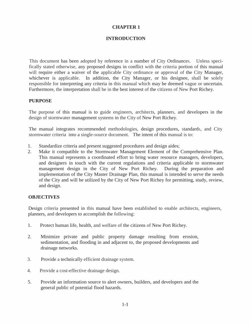
CHAPTER 1
INTRODUCTION
This document has been adopted by reference in a number of City Ordinances. Unless speci
fically stated otherwise, any proposed designs in conflict with the criteria portion of this manual
will require either a waiver of the applicable City ordinance or approval of the City Manager,
whichever is applicable. In addition, the City Manager, or his designee, shall be solely
responsible for interpreting any criteria in this manual which may be deemed vague or uncertain.
Furthermore, the interpretation shall be in the best interest of the citizens of New Port Richey.
PURPOSE
The purpose of this manual is to guide engineers, architects, planners, and developers in the
design of stormwater management systems in the City of New Port Richey.
The manual integrates recommended methodologies, design procedures, standards, and City
stormwater criteria into a single-source document. The intent of this manual is to:
1. Standardize criteria and present suggested procedures and design aides;
2. Make it compatible to the Stormwater Management Element of the Comprehensive Plan.
This manual represents a coordinated effort to bring water resource managers, developers,
and designers in touch with the current regulations and criteria applicable to stormwater
management design in the City of New Port Richey. During the preparation and
implementation of the City Master Drainage Plan, this manual is intended to serve the needs
of the City and will be utilized by the City of New Port Richey for permitting, study, review,
and design.
OBJECTIVES
Design criteria presented in this manual have been established to enable architects, engineers,
planners, and developers to accomplish the following:
1. Protect human life, health, and welfare of the citizens of New Port Richey.
2. Minimize private and public property damage resulting from erosion,
sedimentation, and flooding in and adjacent to, the proposed developments and
drainage networks.
3. Provide a technically efficient drainage system.
4. Provide a cost-effective drainage design.
5. Provide an information source to alert owners, builders, and developers and the
general public of potential flood hazards.

1-2
6. Maintain or enhance the quality and quantity of groundwater supplies.
7. Present guidelines to design for the beneficial use of water resources.
8. Reduce the occurrence and loading of contaminants into natural water bodies.
9. Harmonize, to the greatest practical extent, City of New Port Richey design criteria with
those of other agencies.
10. Provide for the least possible disturbance to community welfare and to the environment
during construction.
11. Develop Best Management Practices (BMPs) to utilize public open space for water
storage while producing an aesthetically pleasing appearance.
Cooperation between the developer and the City of New Port Richey is necessary since many of
the objectives are attainable only when a balance between public and private goals is reached.
This is especially true since many of the objectives are controlled by the specific design.
BACKGROUND
The existing natural features in the New Port Richey area offer both positive and negative
impacts on the drainage system. The relatively low, flat topography of the City helps to control
stormwater velocities. Also, most of the drainage basins in the City slope toward the
Pithlachascotee River. Thus, the river serves as part of the natural drainage system. Negative
features of the natural characteristics consist of a relatively high water table, a low coastal area,
and stormwater pollution. Soils are generally poorly drained and much of the natural vegetation
has been removed.
EXISTING CONDITIONS
Much of the City's existing community development is located within the 100-year floodplain and
took place prior to the implementation of the State's stormwater regulations. Thus, the
combination of increased impermeable surfaces and decrease in vacant land and open area have
created drainage problems. These problems include diminished drainage system capacities,
decreased water recharge, increased stormwater pollution, and an increase in flood-prone areas.
The major drainage problem facing the City is the flooding of selected intersections during heavy
rains.
While it is recognized that the most logical and cost effective means of avoiding damage by
flooding is through the proper location and design of community development, the application of
this approach would be difficult at best since much of the flood-prone area in the City has already
been built upon.

1-3
ENVIRONMENTAL IMPACTS
The Pithlachascotee River and Orange Lake have been disturbed through urbanization, loss of
habitat as a result of hardened shorelines and water quality degradation from stormwater runoff.
Water quality degradation of the river can be traced to stormwater runoff from agriculture and
road and urban areas. The reduction in water quality or a change in the quantity of water found in
the river would have a direct effect on the productivity of the nearby saltwater wetlands. The
situation with Orange Lake is similar to that of the river in that it is directly affected by urban
stormwater pollution.
PROJECTED NEEDS
At the present time, the City of New Port Richey does have a master drainage plan. However,
drainage improvements have been done on a "piece meal basis". The City is currently prioritizing
the drainage projects that have been identified.
REGULATIONS
The Southwest Florida Water Management District (SWFWMD) regulates drainage through
the provisions of Chapters 17-25, 40D-4, 40D-40, and 40D-400 F.A.C., as amended. The
amended regulations call for stricter treatment and retention permitting criteria for surface
water management systems. Projects that have already received conceptual approval will be
"grandfathered" under the criteria currently in effect. There are no provisions under state,
regional, or local rules that provide for retrofitting stormwater systems. Therefore, correcting
existing drainage problems is subject to the availability of local government funding.
The City regulates drainage through its Code of Ordinances and those of the SWFWMD as they
both exist and may be amended from time to time. Once a Plan has been submitted, accepted for
review and approved within six (6) months of the initial submittal date, the regulations in effect at
the time of the submittal will govern, until the approval expires.
It is acknowledged that under present conditions, there is no guarantee that those regulations
currently in place, meet the drainage needs of the City. Therefore, in recognition of this fact, an
examination of the strengths and deficiencies of existing regulations and/or the need for any
additional regulations, will be made from time to time.

1-4
MASTER DRAINAGE PLAN
As a result of the development pattern of the community, its physical location and natural
surroundings, as well as the general lack of engineering data, information necessary to address
the data and analysis requirements of Section 9J-5.011 has not been available. In recognition of
the importance of such information to the health, safety, and welfare of the City, it is proposed
that a master drainage plan be implemented which will incorporate drainage requirements into its
base line data.
CAPITAL IMPROVEMENT DRAINAGE PROJECTS
The City is in the process of implementing a master drainage improvement program, and
incorporating certain drainage improvements into the City's current 5-Year Capital Improvements
Budget, the full implementation remains an on-going process.

2-1
CHAPTER 2
GOALS, OBJECTIVES AND POLICIES
Goal 1
REDUCE EXISTING AND AVOID FUTURE FLOODING PROBLEMS AND
IMPROVE SURFACE WATER QUALITY IN THE CITY OF NEW PORT RICHEY.
Objective 1.1
Establish the following Level of Service (L.O.S.) Standards for planning capital
improvements and reviewing application for development approval.
Policy 1.1.1
Limit the rate of stormwater discharge from new developments to amounts which
are equal to, or less than, the rate of discharge which existed prior to
development in accordance with the Rules of Chapter 40D-4, 40D-40 and
40D-400 F.A.C., administered in the Southwest Florida Water Management
District.
Policy 1.1.2
Regulate the volume of stormwater discharge in accordance with the Rules of
Chapter 40D-4, 40D-40 and 40D-400 administered in the Southwest Florida Water
Management District.
Policy 1.1.3
Require at minimum that on-site drainage facilities for any new project attenuate
the stormwater runoff resulting from a 24-hour/25-year storm.
Policy 1.1.4
Require at a minimum that off-site conveyance systems for any new project carry
runoff from a 24-hour/25-year storm.
Policy 1.1.5
Require all new projects be designed and constructed to treat the amount of
rainfall/runoff prescribed by the Rules of Chapter 40D-4, 40D-40 and 40D-400
administered in the Southwest Florida Water Management District. The City of
New Port Richey shall monitor the implementation of these regulations and, if
necessary, develop an appropriate alternative strategy.

2-2
Policy 1.1.6
Require the placement of structures or impervious surfaces within the 25-year floodplain
be limited commensurate with the ability of the project to adequately mitigate potential
flood impact via compensating storage volumes, and with due consideration of potential
flood impact upon adjacent properties.
Policy 1.1.7
Require that all development and redevelopment within the 100-year Riverine floodplain
be compensated by creation of storage for an equal or greater volume elsewhere within the
100-year floodplain in a manner so as to be able to provide for effective compensation of
the proposed encroachment. Areas solely within the Riverine 100-year floodplain,
immediately adjacent to a tidally produced 100-year floodplain, influenced water body
shall not be subject to this level of service performance standard on the Gulf of Mexico.
Policy 1.1.8
Rights-of-way and unused easements may be used for drainage purposes. provided
this will not cause roadway flooding, are not planned for future use and are deemed
appropriate for such use.
Policy 1.1 .9
Regulate the use of flood plains in accordance with the City of New Port Richey Flood
Damage Prevention Ordinance and to comply with Federal requirements under the
National Flood Insurance Program.
Policy 1.1.10
Require that all proposed buildings within the 100-year floodplain shall be constructed so
that finished floor elevations are a minimum of 12 inches above the elevation of the 100-
year flood, as indicated by the Federal Insurance Rate Map in effect at the time of
building permit application or as established by site survey.
Policy 1.1.11
Develop a public participation education program to provide the general public with
input into stormwater management policies, procedures and practices.
Policy 1.1.12
Permit floodplains to be used for conservation, recreation and open space.
2-3
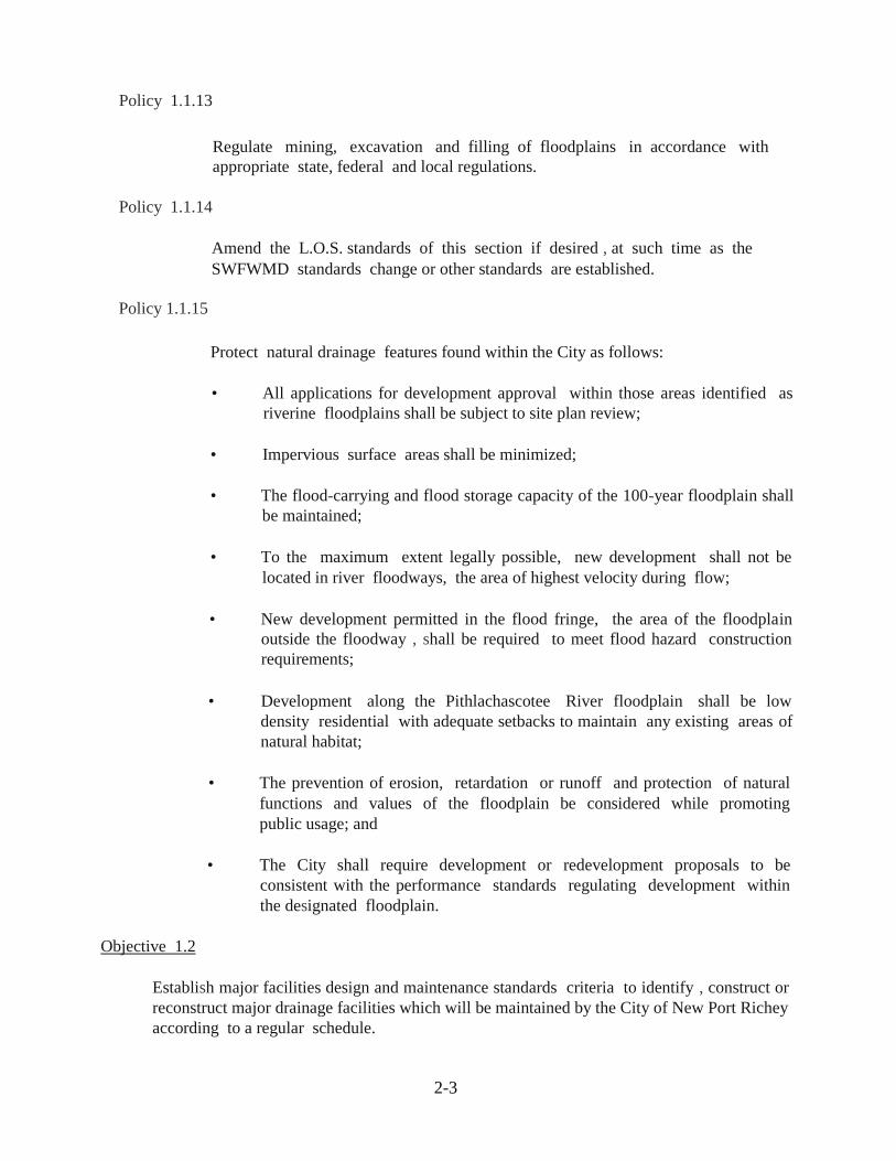
Policy 1.1.13
Regulate mining, excavation and filling of floodplains in accordance with
appropriate state, federal and local regulations.
Policy 1.1.14
Amend the L.O.S. standards of this section if desired , at such time as the
SWFWMD standards change or other standards are established.
Policy 1.1.15
Protect natural drainage features found within the City as follows:
• All applications for development approval within those areas identified as
riverine floodplains shall be subject to site plan review;
• Impervious surface areas shall be minimized;
• The flood-carrying and flood storage capacity of the 100-year floodplain shall
be maintained;
• To the maximum extent legally possible, new development shall not be
located in river floodways, the area of highest velocity during flow;
• New development permitted in the flood fringe, the area of the floodplain
outside the floodway , shall be required to meet flood hazard construction
requirements;
• Development along the Pithlachascotee River floodplain shall be low
density residential with adequate setbacks to maintain any existing areas of
natural habitat;
• The prevention of erosion, retardation or runoff and protection of natural
functions and values of the floodplain be considered while promoting
public usage; and
• The City shall require development or redevelopment proposals to be
consistent with the performance standards regulating development within
the designated floodplain.
Objective 1.2
Establish major facilities design and maintenance standards criteria to identify , construct or
reconstruct major drainage facilities which will be maintained by the City of New Port Richey
according to a regular schedule.
2-4
Policy 1.2.1
Require all new drainageways to use swales, rather than steep-sided, cross
sections where possible.
Policy 1.2.2
Construct or require to be constructed, detention/retention basins in accordance
with rules and procedures which the City of New Port Richey shall prescribe.
Policy 1.2.3
Require all new developments to provide on-site detention and treatment of
stormwater runoff to remove oils, floatables, silt, sediment, nutrients, and heavy
metals.
Policy 1.2.4
Require community associations, homeowner associations, developers and other
third parties to retain ownership and maintenance of drainage systems except for
components as the City of New Port Richey shall prescribe.
Policy 1.2.5
Prohibit excavation of any retention/detention basin to a depth which may
adversely affect the Floridian aquifer.
Policy 1.2.6
Require stormwater systems to be designed to decrease velocity, enhance
percolation and allow suspended solids to settle out. This policy shall not be
construed to prohibit certain components such as bridge or culvert crossings
which may increase velocity with no adverse impact on properties upstream.
Objective 1.3
Regulate development in a manner that will minimize adverse hydrological impacts.
Policy 1.3.1
Require development and redevelopment in any area adjacent to environmental wetlands to be situated , designed, and constructed so as to minimize the adverse impacts on the beneficial characteristics and functions of wetlands.

2-5
Policy 1.3.2
Encourage the restoration of altered wetlands.
Goal 2 (Goal, objectives, and policies are consistent with those set forth in the City of
New Port Richey Comprehensive Plan, Infrastructure Section)
AN EFFICIENT MASTER DRAINAGE SYSTEM WHICH PROTECTS HUMAN
LIFE, MINIMIZES PROPERTY DAMAGES AND IMPROVES STORMWATER
QUALITY AND ON-SITE RETENTION SHALL BE PROVIDED.
Objective 2.1
As of the effective date of the Comprehensive Plan, or until such time as a Master
Drainage Plan is operational, the City shall continue to maintain, and where necessary,
improve the existing stormwater drainage system located within its municipal boundaries.
Policy 2.1.1
The following management techniques shall be, at minimum, used to implement
the drainage plan (25-year frequency, 24-hour storm event):
• No more than 40 percent of residential lots and 70 percent of commercial
lots shall be covered with paving or other types of impervious surfaces.
• Expansion and regular maintenance of retention swales adjacent to City
roadways.
• Use of front, rear and side lot line swales in new development.
• Use of erosion and runoff control devices during development
construction.
• In low areas, frequently inundated by stormwater flooding, the City shall
consider construction of drainage retention areas, in the public right-of
way particularly to retain the stormwater currently being discharged into
Orange Lake and overflowing into the Pithlachascotee River and basin.
• Where necessary, the City shall consider construction of drainage
retention areas in the public right-of-way and the use of eminent domain
condemnation to acquire property for drainage retention purposes.
• The City should continue to implement stormwater management
techniques to correct the flooding on Main Street in front of City Hall, and
in the N. Adams, Franklin, S. Riverview, Meadow Lane and Jasmine
Heights areas.

2-6
• Where the shoreline of the Pithlachascotee River is not seawalled native
vegetation shall be used for shoreline stabilization.
• The replacement material for failed or damaged rip-rap along the
Pithlachascotee River concrete seawalls should be rip-rap or planting of native
marine vegetation where technically feasible.
• Where cost effective, the rehabilitation of drainage facilities during road
repairs and improvements shall be conducted.
Policy 2.1.2
The drainage system LOS standard is hereby established.
On-site: Retain the difference in pre- and post-development peak runoff for a 25-
year, 24-hour storm event.
Off-site: Conveyance system to carry runnoff from 10-year, 24-hour storm event.
Objective 2.2
The City of New Port Richey shall continue implementation of the Master Drainage Plan.
Policy 2.2.1
The City shall continue the drainage improvements fund, financed by proportionate
assessment of City property owners for:
Acquisition of required drainage easements.
Construction bonds for required drainage improvements.
Operation and maintenance costs.
Policy 2.2.2
Consistent with budget allocations, the City shall establish a program for retrofitting (i.e.,
rehabilitation during road repairs and improvements) of the system's existing deficiencies
to conform to the Master Drainage Plan.
Goal 3 (Goal , objectives, and policies are consistent with those set forth in the City of
New Port Richey Comprehensive Plan, Infrastructure Section)
THE NATURAL GROUNDWATER AQUIFER RECHARGE AREAS WITHIN THE
CITY AND WITHIN THE CITY 'S FACILITY SERVICE AREA SHALL BE
PROTECTED AND MAINTAINED.
Objective 3.1

2-7
Regulations shall be adopted which provide protection to prime recharge areas located
within the City.
Policy 3.1.1
As presented in Objective 4.2 of the Future Land use Element and pursuant to Section
373.3095, Florida Statutes, the City shall adopt provisions within its land development
regulations which provide special protection to those areas identified as prime
recharge located within the City .
Policy 3.1.2
The City shall cooperate with SWFWMD in its inventory and identification of those
prime recharge areas within and adjacent to the City pursuant to Sections 373.0395(3)
and 373.1397, Florida Statutes.
Policy 3.1.3
Areas with the greatest recharge potential and which are undeveloped shall be
classified as prime recharge areas, and they shall be considered as candidates for
designation as Preservation or other suitable land use designation, as deemed
appropriate by SWFWMD, on the Future Land Use Map.
Policy 3.1.4
Areas of prime recharge within the City not designated as preservation areas, shall
be regulated by limiting impervious surface, water quality monitoring, and other
regulations which limit intense development, and shall require retention of the 25-year
frequency, 24-hour storm event on-site to allow for maximum recharge.
Policy 3.1.5
Areas of prime water recharge shall be buffered from wastewater or solid waste
products.
Objective 3.2
The City will, when feasible, assist SWFWMD, WCRWSA and Pasco County to prevent
saltwater intrusion and other contaminants from adversely affecting the groundwater supply
serving the City of New Port Richey.
Policy 3.2.1
The City shall cooperate with SWFWMD, WCRWSA and Pasco County in identifying
and analyzing saltwater intrusion and other water quality hazards that affect the City of
New Port Richey and its potable water supply service areas.
Policy 3.2.2

2-8
Adverse water quality shall be reported to the affected local governments and agencies
and appropriate corrective measures, suitable to the quantity, type, and nature of the
contaminate, shall be cooperatively undertaken.
Policy 3.2.3
The City shall ensure that all land development projects which occur subsequent to the
adoption of the Comprehensive Plan shall meet water quality standards contained in
Southwest Florida Water Management District (SWFWMD Chapters 40D-4, 40D-40
and 40D-400, F.A.C.).
Objective 3.3
Protect the quality of lakes, rivers, streams, marine and freshwater wetlands, other
watercourses and natural drainageways and drainage basins in the City of New Port
Richey.
Policy 3.3.1
Design drainage systems to prevent the channelization of stormwater runoff
directly into natural surface waterbodies.
Policy 3.3.2
Encourage the appropriate use of natural waterbodies, watercourses, and wetlands
for water quality improvement with all necessary environmental and design
controls. Adequate erosion and sedimentation control practices shall be used to
protect natural waterbodies, watercourses, and wetlands from siltation and runoff
from development and agricultural activities.
Policy 3.3.3
Prohibit encroachment into and the drainage of wetlands and submerged lands
unless permitted by the appropriate agencies (i.e., SWFWMD, FDEP).
Policy 3.3.4
Preserve wetland and transitional vegetation located in floodplain buffer zones as
defined by the Conservation and Coastal Zone Elements.
Policy 3.3.5
Prohibit the widening, straightening, stabilizing, or otherwise altering of natural
watercourses except in cases of overriding public interest.
3-1
CHAPTER 3
REQUIREMENTS FOR A STORMWATER MANAGEMENT
PLAN AND REPORT
Unless specifically exempted, modified, or waived pursuant to the City's development review
procedures, a copy of the issued FDEP-NPDES-NOI Permit, the issued Construction Permit or
Permit Exemption from the Southwest Florida Water Management District, and a
Stormwater Management Plan meeting the requirements of this Manual, must be submitted
and approved before commencing development. Said plan shall comply with the following
standards:
3.1 General Standards
3.1.1 The hydrologic requirements mandated by this Manual shall be developed in
accordance with the latest releases and revisions of the U.S. Department of
Agriculture, Soil Conservation Service's Technical Release No. 55 entitled
"Urban Hydrology for Small Watersheds", SCS National Engineering Handbook,
Section 4, entitled "Hydrology", and applicable supplements thereto. Alternate
methods may be used if, in the opinion of the Development Review Committee,
the method produces similar results to the above listed technical guides.
3.1.2 Innovative approaches to stormwater management shall be encouraged and the
concurrent control of erosion, sedimentation, water pollution and flooding shall
be mandatory.
3.1.3 The design of water retention or detention structures and flow attenuation devices
shall be subject to the approval of the Development Review Committee pursuant
to the requirements of this regulation.
3.1.4 Runoff computation shall be based upon the designated regulatory criteria
(rainfall duration, distribution and antecedent soil moisture condition), and conform
to acceptable engineering practices using rainfall data and other local information
applicable to the affected area.
3.1.5 All stormwater management facilities shall be designed for a minimum of twenty
(20) year life, have low maintenance cost, and adequate legal access for
periodic maintenance.
3.1.6 No site alteration shall allow water to become a health hazard or contribute to the
breeding of mosquitoes.
3.1.7 The drainage area used in runoff calculation shall be the total existing and natural
watershed area including areas beyond proposed site limits.

3-2
3.1.8 All proposed stormwater management systems shall be designed to prevent flood, safety or health hazards.
3.1.9 All stormwater management systems shall be designed to enhance groundwater
recharge while reducing pollution. However, in an area designated as a groundwater recharge area, the developer shall take all possible measures to limit runoff from the proposed site. In addition, the Development Review Committee, while enforcing standards set for pollution and sedimentation control, may encourage or request innovative approaches to achieve the above-stated purpose.
3.1.10 A stormwater management system shall be provided for protecting lots, roads
and streets from the potential adverse impacts of stormwater runoff and for handling stormwater runoff that comes into or across the site plan from the outside. Soil types shall be considered and ultimate land usage assumed for selection of proper runoff coefficients within the drainage areas involved. The system shall be designed in accordance with accepted engineering principles to attenuate to predevelopment levels.
The system shall be designed for low maintenance cost and ease of maintenance by normal maintenance methods. The City may require such data as is determined to be necessary from the applicant to provide the adequacy of the design of the water management system.
3.1.11 The applicant shall provide facilities to hold stormwater on-site per the
requirements of this section or to drain the runoff to positive outfalls that can be legally maintained in permanent use, or to a public drainage system with adequate capacity which discharges into positive outlets. If the applicant elects to utilize a public drainage system, the applicant must have the consent of the governing body which exercises control over the public drainage system.
3.1.12 In the event the applicant elects to drain to a public drainage system, the
applicant, at his own expense, may be required to modify the public drainage system in part or in whole, including but not limited to storm sewers, inlets, ponds, control structures, side ditches or roadside swales adjacent to public roads over which the drainage will flow. Any such modification shall be subject to the approval of any governing body having jurisdiction over the public drainage system.
3.1.13 Projects that are to be developed in phases will require the submission of a master
plan of the applicant's contiguous land holdings. Applications for individual project phases may be considered only when the phases are consistent with the approved master plan.
3.1.14 All Projects and their Plans shall be designed to be fully compliant with the current
Florida Department of Environmental Protection (FDEP) State of Florida Municipal Separate Storm Sewer System Permit (MS4) Number FLS 000032-003 issued 12/01/2011 and as may be amended from time to time.

3-3
3.2 Performance and Maintenance Standards - Stormwater management plans must
demonstrate the proposed development activity has been planned, designed, and will be
constructed and maintained to meet each of the following performance standards:
3.2.1 To limit the post-development hydrograph for the developed site so that rate of
flow, volume (in a closed basin), and timing shall not exceed pre-development
conditions;
3.2.2 To protect or improve the quality of ground and surface water;
3.2.3 To insure that there is no erosion after development;
3.2.4 To maintain groundwater levels and enhance groundwater recharge;
3.2.5 To protect the beneficial function of wetlands, such as swamps, bogs, marshes,
estuaries, sloughs, floodplains, for the natural storage of surface waters and the
biological reduction and assimilation of pollutants;
3.2.6 To prevent saltwater intrusion by adhering to applicable best management
practices;
3.2.7 To prevent increased flooding and damage that result from improper location,
construction and design of structures in areas which are presently susceptible to
dangers of flooding;
3.2.8 To protect the natural fluctuating levels of salinity in estuarine areas;
3.2.9 To minimize injury to flora and fauna , and adverse impacts to fish and wildlife
habitats;
3.2.10 Retention and detention ponds shall be used to retain and detain the
increased and accelerated runoff which the development generates. Water shall be
released from detention ponds into watercourses, wetlands, existing
stormwater management facilities, etc., at a rate and in a manner approximating
the natural flow which would have occurred before development;
3.2.11 The area of land disturbed by development shall be as small as practicable. Those
areas which are not to be disturbed shall be protected by an adequate barrier from
construction activity. Whenever possible, natural vegetation shall be retained and
protected;
3.2.12 No grading, cutting or filling shall be commenced until erosion and sedimentation
control devices have been installed between the disturbed area and water bodies,
watercourses, and wetlands;
3.2.13 Land which has been cleared for development and upon which construction will

3-4
not commence and continue within 30 days shall be protected from erosion and
sedimentation by appropriate techniques;
3.2.14 On sites greater than one acre, if more than one contiguous acre is cleared,
a ground cover sufficient to prevent erosion shall be planted or otherwise
provided within 10 working days on that portion of the site upon which
further active construction will not be undertaken within 90 days;
3.2.15 Sediment shall be retained on the site of the development;
3.2.16 Wetlands and other water bodies shall not be used as sediment traps during
development;
3.2.17 Erosion, sedimentation and all stormwater management system facilities shall
receive regular maintenance to ensure that they continue to function properly.
This shall be done by the Developer or the approved Operation and Maintenance
Entity. Should this not be done, then the City of New Port Richey is hereby
granted access and authorized to perform maintenance operations they deem
necessary to protect the health, safety and welfare of the public and to charge the
Developer or approved Maintenance Entity for these costs, who hereby agrees to
pay and be responsible for these costs within 60 days of notification.
3.2.18 Development, including grading and contouring, shall take place m a manner
that protects the roots and stability of trees.
3.3 Design and Maintenance Standards - To insure attainment of the objectives of this
regulation and to insure that the performance standards will be met, the design,
construction and maintenance of drainage systems shall be consistent with the following
standards:
3.3.1 The hydrograph for the developed or redeveloped site shall not exceed the rate
of flow, volume (in a closed basin), and timing of runoff produced by conditions
existing before development or redevelopment, unless runoff is discharged into
an off-site drainage facility as provided in Section 3.3.10 below.
3.3.2 Channeling runoff directly into water bodies shall be prohibited. Instead, runoff
shall be routed through swales and other systems designed · to increase time of
concentration, decrease velocity, increase infiltration, allow suspended solids to
settle and remove pollutants.
3.3.3 Natural watercourses shall not be dredged, cleared of vegetation, deepened,
3-5
widened, straightened, stabilized, or otherwise altered. Water shall be retained
or detained before it enters any natural watercourse in order to preserve the
natural hydro-dynamics of the watercourse in order to preserve the natural hydro
dynamics of the watercourse and to prevent siltation or other pollutions.
3.3.4 Artificial watercourses shall be designed, considering soil type, so that the
velocity flow is low enough to prevent erosion.
3.3.5 Vegetated buffer strips shall be created or, where practical, retained in their
natural state along the banks of all watercourses, water bodies, or wetlands. The
width of the buffer shall be sufficient to prevent erosion, trap the sediment and
overland runoff, provide access to the water body and allow for periodic flooding
without structures.
3.3.6 Detention and retention areas shall be designed so that shore lines are sinuous
rather than straight and so that the length of shoreline is maximizing, thus
offering more space for the growth of littoral vegetation.
3.3.7 The banks of wet detention and retention areas shall slope at a gentle grade
(maximum 4:1) into the waters as a safeguard against drowning, personal injury
or other accidents, to encourage the growth of vegetation, and to allow the
alternate flooding and exposure of areas along the shore as water levels
periodically rise and fall. Fencing (6 feet tall chain link - from existing ground))
may be allowed as an alternative.
3.3.8 The use of drainage detention and vegetated buffer zones as open space,
recreation and conservation areas shall be encouraged.
3.3.9 The developer shall be responsible for obtaining any necessary permits for the
stormwater management system required by local, state or federal agencies.
3.3.10 The Development Review Committee may allow stormwater runoff to be
discharged into drainage facilities off the site of development if each of the
following conditions is met:
a. It is not practicable to completely manage runoff on the site in a manner
that meets the performance and design standards;
b. The off-site drainage facilities and conveyance system leading to them are
designed, constructed and maintained in accordance with the -
requirements of this manual;
c. Adequate provision and written agreements for use of the land are made for the
sharing of construction, maintaining and operating costs of the facilities. The
developer may be required to pay a portion of the cost of constructing the

3-6
facilities as a condition to receiving approval of the drainage plans; and
d. Adverse environmental impacts on the site of development will be
minimized.
e. A request to use off-site drainage facilities and all information related to
the proposed off-site facilities shall be made a part of the developer's
approved stormwater management plan.
3.4 Contents of a Stormwater Management Plan - It is the responsibility of the applicant to
include in the stormwater management plan sufficient information for the Development
Review Committee to evaluate the environmental characteristics of the affected area, the
potential and predicted impacts of the proposed activity on community waters, and the
effectiveness and acceptability of those measures proposed by the applicant for reducing
adverse impacts. The stormwater management plan shall contain maps, charts, graphs,
tables, photographs, computations, narrative descriptions and explanations, and citations
to supporting references, as appropriate to communicate the information required by this
section.
The Stormwater Management Plan shall, at a minimum, contain the following
information:
3.4.1 The name, address, and telephone number of the applicant and the engineer.
3.4.2 A location map.
3.4.3 The existing environmental, topographic (1 ft. contours and basis) and hydrologic
conditions of the site and/or receiving waters and wetlands, and all drainage basins -
on and off site shall be described in detail, including the following:
a. The direction, flow rate, and volume (in a closed basin) of stormwater runoff
existing conditions, pre-development conditions; and post-development
conditions;
b. The location of areas on the site where stormwater collects or percolates into the
ground;
c. A description of all watercourses, water bodies, and wetlands on or
adjacent to the site or into which stormwater flows;
d. Groundwater levels, including seasonal fluctuations; location of
floodplains;

3-7
e. Vegetation;
f. Topography;
g. Soils.
h. Other items consistent with the SWFWMD criteria.
3.4.4 Proposed alterations of the site shall be described in detail, including:
a. Changes in topography;
b. Areas where vegetation will be cleared or otherwise killed;
c. Areas that will be covered with an impervious surface and a description of the
surfacing material; the size and location of any buildings or other structures.
3.4.5 All components of the proposed storm water management drainage system and any
measures for the detention, retention, or infiltration of water or for the protection of
water quality shall be described in detail, including:
a. The channel, direction, flow rate, volume (in a closed basin), and quality of
stormwater that will be conveyed from the site, with a comparison to existing
conditions and pre-development and post-development conditions; detention and
retention areas, including plans for the discharge of contained water, maintenance
plans, and predictions of water quality in those areas; areas of the site to be used
or reserved for percolation;
b. A plan for the control of erosion and sedimentation, which describes in detail the
type and location of control measures, the stage of development at which they
will be put into place or used, and provisions for their maintenance.
c. Any other information which the developer or the Development Review
Committee believes is reasonably necessary for an evaluation of the development.
3.4.6 Construction plans and specifications for all components of the Stormwater
Management System.
3.4.7 The Stormwater Management Plan shall be prepared and sealed by a Professional
Engineer registered in the State of Florida.

4-1
CHAPTER 4
GENERAL DRAINAGE STANDARDS/CRITERIA
All proposals for development or redevelopment shall include a detailed stormwater management
plan to be submitted for approval by the City of New Port Richey. The plan shall illustrate the
means by which compliance with the intent of the stormwater management policies of the
City will be achieved. Maintenance overlays of existing parking lots shall require a
certification that the proposed maintenance overlay construction activity will be made in a
manner that does not change the existing drainage pattern within the parking lot or have an
adverse effect on adjacent off-site areas. All plans, maps, data, computations, certifications,
etc. required by this manual shall be prepared and sealed by a Professional Engineer registered
in the State of Florida.
GENERAL
All new developments and redevelopments shall be required to provide a detention/retention
system in order to detain/retain increased runoff caused by the development/redevelopment.
Where public or private lakes, ponds, borrow pits, or similar type water detention/retention areas
are incorporated in a comprehensive drainage plan, drainage calculations shall demonstrate that
the facilities have sufficient capacity for the design storm. In the design of detention/retention
facilities, the effective volume shall be based on the pond bottom or the seasonal high
groundwater level, whichever is higher, as a minimum starting elevation of the stage/storage
computations.
REQUIREMENTS APPLICABLE TO ALL DEVELOPMENTS REQUIRING REVIEW
4.1 Drainage Review
4.1.1 A drainage review will be required regardless of size for all of the following
types of developments.
a. Residential/Subdivision
b. Commercial
c. Industrial
d. Multi-family/Non-subdivision
4.1.2 Impervious areas shall include, but not be limited to:
a. Buildings
b. Asphalt surface
c. Concrete
d. Shell e. Limerock
f. Water
g. Paver Block/Turf Block

4-2
h. Any other material either temporary or permanent which will shed over
70% of the water falling upon it.
4.1.3 These standards, unless otherwise noted, shall apply to all developments
requiring review.
4.2 Outfall Conditions
All outfall conditions are classified by the City as more than adequate, a d e q u a t e , peak
sensitive or volume sensitive. I t is the responsibility of the Developer's Design
Engineer to study the outfall condition for a project site area based upon the following
criteria:
4.2.1 More than adequate outfall:
a. These outfalls are usually located adjacent to sizable water bodies (i.e.
large streams and rivers, etc. which are large enough to allow an
increase in discharge without causing harm. The requirements for any
proposed construction or upgrading of connecting facilities to these
sizable water bodies will be established on a case-by-case basis by the
City Engineer and will include a minimum design event of the 100-year
return frequency assuming post-development conditions. It is strongly
recommended that the Developer's Design Engineer have a pre-design
meeting with the City Engineer prior to submitting the site design of
more than adequate outfalls in the City.
b. The Developer must submit a drainage plan along with his design which
demonstrates that direct discharge to the outfall without attenuation of
flow will not result in any adverse impacts.
c. This in no way precludes the Detention Treatment Requirements of any
other local, state, or federal agency.
4.2.2 Adequate outfalls
a. These outfalls have no known inadequacies or flooding conditions but
would experience an increase in water elevation if the discharge rate
were increased.
b. Developments discharging into this type outfall must be designed with
post-development peak discharge rates due to a 25-year, 24-hour storm
event not to exceed the pre-development peak discharge rate for the 25-
year, 24-hour storm event.
c. Sheetflow is not considered to be an adequate outfall unless specifically
approved by the City Engineer.

4-3
4.2.3 Peak Sensitive (Outfalls with inadequate flow capacity):
a. These outfalls generally have histories of flooding problems related to
resistance and restrictions within the channel and/or inadequate
conveyance structures.
b. Developments discharging into this type outfall must be designed to meet
the more stringent of the following conditions:
1. Post-development peak discharge rate for the 25-year, 24-hour
storm event is not to exceed pre-development peak discharge rate
for the 10-year 24-hour storm event.
2. The post-development flow rate is not to exceed the area weighted
capacity of the outfall unless the Developer's Design Engineer can demonstrate that a different discharge rate should be used for the design. The outfall capacity shall be that which does not result in adverse flooding or erosion of adjacent properties.
4.2.4 Volume Sensitive
a. This classification pertains to development which drains into areas that
do not have a positive outfall.
1. A positive outfall is defined as a man-made or natural canal,
swale, waterway or other conveyance system . Sheetflow is not a
positive outfall unless specifically approved by the City.
2. In such areas the site shall be designed in accordance with either of
the following criteria:
• The difference between the pre-development and post
development runoff volumes, due to the 100-year , 24-hour
rainfall event, shall be retained on-site. The design storage
volume must be again available within 72 hours after the
end of the design storm event. The Developer's Design
Engineer must demonstrate that percolation, alone, is
sufficient to discharge the design volume within the 72-hour
period.
• The total post-development runoff volume due to the 100-
year, 24-hour rainfall event shall be retained or detained on
site. The pond shall be designed to bleeddown, during the
100-year design event, at a rate which will result in a
discharge of no more than and no less than approximately
one inch of runoff from the total area contributing to the
pond within 24 hours of the inception of inflow to the
pond. An exception can be made by the City when other

4-4
agency bleeddown criteria is more stringent. When
percolation is the only means of discharge from the pond,
then one inch of runoff is the minimum volume to be
discharged in the 24-hour period described above. The
Developer's Design Engineer must demonstrate this. 4.3 Frequency
The system at a minimum, shall be designed for "design storms" resulting from rainfall of
the following frequencies as stated below.
4.3.1 10-Year - All storm sewers and culverts, except those crossing arterial roads.
A minimum time of concentration of 15 minutes to the first inlet may be
utilized in determining design flows.
4.3.2 25-Year/24-Hour - All floodways, ditches, channels, and detention/retention
areas with outfalls (open drainage basin).
4.3.3 50-Year - All storm sewer and culverts crossing arterial roads.
4.3.4 100-Year/24-Hour - All retention areas without outfalls (closed drainage basin).
Rainfall intensity factors shall come from accepted meteorological and rainfall sources
applicable to the City of New Port Richey.
4.4 Development Criteria in Floodplains
4.4.1 The criteria for development in floodplains pertains to all floodplains and is not
limited to those defined on FEMA maps. The Developer's Design Engineer is
responsible for determining the on-site 100-year flood elevations if not
defined by a FEMA detailed study. The Developer's Design Engineer is
encouraged to submit a Letter of Map Amendments to FEMA for any
changes in flood zone designations as determined by detailed study of the
area.
4.4.2 No development (structures and/or fill) shall be allowed in the conveyance
portion of any 100-year frequency floodplain associated with any stream,
channel, lake or waterway unless provisions are made to effectively compensate
for any reduction in conveyance caused by the development.
This does not apply to the 100-year floodplain immediately adjacent to a tidally
produced 100-year floodplain influenced water body for on-site areas. Off-site
areas shall not be impacted in any way.
4.4.3 No development (structures and/or fill) shall be allowed in the Riverine
100-year frequency floodplain unless provisions are made to effectively
compensate for the reduction in storage volume areas due to the proposed
development.
4-5
a. Any compensation volumes must be provided in addition to water deten tion or retention ponds otherwise required to reduce peak runoff rates from the development. Credit for partial usage of pond storage volume for both compensation storage volume and peak discharge attenuation storage volume shall be appropriate if the Developer's Design Engineer can show that it is applicable by a detailed analysis of the hydrologic timing of the water surface elevations within the watershed. For developed conditions, the controlled seasonal high groundwater table elevation will be used in the analysis and design. Controlled seasonal high groundwater is the elevation of the seasonal high groundwater after site modifications are completed.
b. No earth fill many be placed within the Riverine 100-year floodplain area
unless an effective equal amount of flood storage volume is created by excavation below the 100-year flood elevation and above the seasonal high ground water table elevation or controlled seasonal high ground water table elevations, whichever is appropriate.
c. Exceptions are allowed if the floodplain is associated with a landlocked
waterbody and is under one ownership. 4.5 Determination of Storm Runoff
4.5.1 Runoff and routing analysis shall be based on current hydrological design
procedures. Computations shall include a tabulation of inflow, discharge, storage capacity, minimum and maximum water elevations, and retention/ detention time to peak.
4.5.2 Basic hydrological calculations shall be based on commonly accepted procedures
such as those of:
a. Soil Conservation Services (S.C.S.)
1. " A method for Estimating Volume and Rate of Runoff in Small Watersheds", U.S. Department of Agriculture, S.C.S. Technical Paper No. 149.
2. "Urban Hydrology for Small Watersheds" , U.S. Department of Agriculture, S.C.S. Technical Release No. 55.
3. "National Engineering Handbook, Section 4, Hydrology", U.S. Department of Agriculture, S.C.S., latest edition. The Soil Conservation Service, Type II, Florida Modified Rainfall
Distribution with Antecedent Moisture Condition II will be used. Other rainfall distributions may be utilized for design with the prior approval of the City. The same shape factor shall be used for pre-development and post-development calculations, unless otherwise approved by the City of New Port Richey.
4-6
b. Rational or Modified Rational Method
1. "Drainage Manual", See the 2008 Drainage Manual by the Florida
Department of Transportation. Volumes 2A and 2B may be
used as reference documents from the 1987 FDOT Drainage
Manual.
2. Standard Engineering Texts.
The rational method of routing analysis may be used for systems serving
projects with one (1) acre or less of total contributing area.
c. Others as approved by the City of New Port Richey
Ultimate land usage shall be assumed for selection of proper runoff
coefficients, or curve numbers with in the basin involved. Weighted runoff
coefficients, or curve numbers shall be utilities where different coefficients,
or curve numbers exist within the area comprising the basin
4.6 Rainfall Criteria
4.6.1 Rational and Modified Rational Methods
a. The FDOT Zone 6 IDF curves (fig. 2) shall be used in the City of New
Port Richey when designing by the Rational or Modified Rational
Methods.
4.6.2 S.C.S. Synthetic unit Hydrograph Methods
a. The SWFWMD rainfall depths found in Figures 3 through 6 are to be used
in the City of New Port Richey when designing by the S.C.S. methods.
b. The only allowable rainfall distribution for design use in the City of New
Port Richey is the S.C.S. Type II Florida Modified rainfall distribution.
This distribution can be found in Table 10-A and B. The same design
rainfall distribution shall be used in the calculation of both pre- and post-
development runoff hydrographs.
4.7 Time of Concentration Determination
4.7.1 The Time of Concentration is a common parameter of the above methods. It is
recommended that the time of concentration be determined by the Velocity
Method.
a. The velocity method is a segmented approach that can be used to account
for overland, shallow channel, and main channel flows by considering
the average velocity for each flow segment, and by calculating a travel
time using the following equation:

4-7
ti = Li (4-1)
_______
(60) Vi
Where:
ti = Travel time for velocity segment (i), in minutes
Li = Length of the flow path for segment (i), in feet
vi = Average velocity for segment (i), in feet/second
b. The time of concentration is then calculated by summing the individual
segment travel times as follows:
tc =
Where: tc = Time of concentration, in minutes t1 = Overland travel time, in minutes t2 = Shallow channel travel time (typically shallow swale or gutter flow), in minutes t3 = Main channel travel time (typically storm sewer, swale, ditch, canal, etc.), in minutes ti = Travel time for the ith segment, in minutes

4-8
1. Overland Flow
The 1987 FDOT Drainage Manuals 2A and 2B serve as useful guidance
documents.
The Kinematic Wave Equation developed by Ragan (1971) should be
used for calculating the travel time for overland flow
conditions. The Kinematic Wave method is the recommended
method for calculating the tin1e of concentration for overland flow.
Other methods may be acceptable, however, the design will be
checked with the Kinematic Wave Equation. Any significant differences
in the calculation of the time of concentration for overland flow by
methods other that the Kinematic Wave Equation must be approved by
the City. This equation, which is expressed as:
ti = 0.93 L0 6 N°·6
I0.4 S0 3 (4.2)
Where:
t1 = Overland flow travel time, in minutes
L = Overland flow length, in feet
N = Surface roughness coefficient for overland flow (see Table
2)
I = Rainfall intensity, in inches/hour, corresponding to the
deign storm frequency
S = Average slope of the overland flow path, in feet/feet
The Figure 11 Nomograph is a design aid.
It should be noted that the surface roughness coefficient values shown in
Table
2 were determined specifically for overland flow conditions and are not to be used
for conventional open channel flow calculations.
Equation 4-2 is solved by a trial and error process as follows:
• Assume a trial value of rainfall intensity (I).
• Determine the corresponding overland travel time (t1) using Figure 11 or
4-9
Equation 4-2.
• Use t1 from Step 2 as the critical storm duration and determine the actual
rainfall intensity for this critical storm duration. Select the appropriate intensity-duration-frequency (IDF) curve from Figure 2.
• Compare the trial and actual rainfall intensities. I f they are different,
select a new trial rainfall intensity and repeat the process.
2. Shallow Channel Flow (e.g. shallow swale, gutter, etc.)
Average velocities for shallow channel flow can be calculated
using Manning's Equation.
3. Main Channel Flow (e.g. Ditch, pipes, etc.)
Average velocities for main channel flow should be calculated
using Manning's Equation.
4.8 Erosion Control Measures
4.8.1 It shall be the responsibility of the developer to control soil erosion by wind or
water from the date of groundbreaking until such time as the responsibility is
transferred to an acceptable entity in accordance with this code.
4.8.2 The Developer 's Design Engineer must provide for use of sediment basins,
strawbale dams, velocity checks, hydroseeding applications, etc., to minimize
erosion within the limits of the site being developed and prevent damage to
wetland systems which are to remain in the development.
4.8.3 Design of canals, streams, ditches, and any other waterways shall be based on
current open channel design procedures using the Chezy, Talbot, and/or
Manning's Formula. Design velocities without erosion protection shall not
exceed the maximums for soil types as shown in Table 7. Where design levels
exceed top of banks for the required design storm (i.e. 25-year for major
waterways), and berms are not provided, the extent of flooding in the floodplain
shall be shown. Runoff and roughness coefficients, safe velocities, nomographs,
erosion control, and practical limitations on use of design formulas shall be
based on current practice in the field of hydraulics, notwithstanding any
requirements of this section.
4.8.4 Conditions such as alignment, and presence of severe irregularities in
smoothness will alter the allowable velocities. Maximum flow velocities for
various soil types without erosion protection are shown in Table 7.

4-10
4.8.5 All roadway construction or repair activities performed by, or under the
supervision of the City of New Port Richey Public Works Department shall be conducted in accordance with the standards set forth in the Florida Department of Transportation Standard Specifications for Road and Bridge Construction (Section 104 Erosion Control) and the policies shall comply with the requirements of Chapter 62-25 Florida Administrative Code CFAC), Environmental Permitting Rules 40D-4, 40D-40 and 40D-400 of Southwest Florida Water Management District and with local environmental codes, and the current FDEP-NPDES Permit for MS4 systems.
4.9 General Criteria for Detention and Retention Ponds
4.9.1 Purpose - The purpose of detention and retention ponds is to serve as a buffer to
attenuate peak flows and/or excess runoff volume from urbanized and developed areas.
4.9.2 Minimum Criteria for Detention/Retention Ponds (All
Development/Redevelopment )
a. A detention or retention pond shall be provided unless otherwise approved by the City. The minimum edge of pavement elevation shall be at or above the design high water elevation, unless otherwise allowed.
b. For the design of detention ponds in an open basin, the instantaneous
peak discharge expected for the undeveloped site due to a 25-year/24-hour rainfall shall not be exceeded by the instantaneous peak discharge from the developed site due to a 25-year/24-hour rainfall unless the site is considered "peak or volume sensitive". The 100-year/24-hour rainfall shall be utilized for a closed basin design.
c. Calculation of the instantaneous peak discharge from the undeveloped
site shall consider the affect of existing storage in attenuating this peak. Pre- and post-development initial elevations for estimating storage shall be the seasonal high water elevation as determined by biological indicators, soil indicators, or other suitable methods and controlled season high water elevations, respectively.
d. Drainage calculations shall include peak discharge . e. Off-site runoff shall be routed around or through the project
without combining with on-site runoff unless the pond and discharge structure are designed to accept this off-site runoff.
f . The 100-year event shall be routed around the project or through the
detention/retention pond. If designed to accept the off-site runoff, it shall be used to establish the minimum residential floor slab elevation or floodproofing elevation (commercial sites only). In no case should residential floor slab elevations or floodproofing elevations be any lower than 1 (one)

4-11
foot above the flood elevations established by FEMA.
g. For commercial sites, a minimum of six inches of freeboard is to be
provided for the 25-year/24-hour storm or the 100-year/24-hour storm,
whichever is the design storm event.
h. For commercial sites, no more than 50% of the required freeboard may
be provided outside of the designated pond area.
i. For commercial sites, some storage may be allowed on top of paved
parking areas when designing to the 100-year criteria, for all outfall
conditions, provided:
1. Developed runoff volume for the 25-year storm event is entirely
stored in the pond.
2. Depth of storage on the pavement does not exceed four inches.
j. Hydrologic and hydraulic calculations shall be provided for each facility
and shall include:
1. Drainage calculations and support information such as:
stagestorage data, stage-discharge data (if applicable), inflow
hydrographs, outflow hydrographs, etc.
2. Input data, when computerized flood routing techniques are
utilized including: basin areas, curve numbers,
Rational coefficients, inflow hydrographs, S.C.S. peak rate factor,
time of concentration values, rainfall distribution data,
stage/storage information, etc.
k. For commercial sites, the maximum sideslope for ponds shall be
no steeper than 4:1. If a request for steeper slopes is granted by the
City, the entire areas of the pond shall be fenced with a minimum six (6)
foot high chain link fence with a twenty (20) foot double swing gate.
l. For subdivisions, the maximum sideslopes for ponds shall be no steeper
than 4:1. (horizontal:vertical)

4-12
m. For subdivisions, wet detention ponds shall have a minimum depth of 6
feet below normal water level and shall have sideslopes no steeper than
4:1 (horizontal:vertical) to a depth of at least 6 feet below normal water
level. The minimum depth requirement will not apply to littoral zones,
however, the sideslope requirements stated above will apply below
normal water level.
n. For subdivisions, the minimum freeboard for ponds shall be six inches
between design high water and top of bank for the 25-year/24-hour
storm or the 100-year/24-hour storm, whichever is the design storm
event. All points within the adjacent maintenance areas shall be at or
above the elevation of the top of bank. When the adjacent property
slopes upward from the outer edge of the maintenance area then
credit will be given for freeboard to the external limit of the
maintenance area. If the outside edge of the maintenance area slopes
downward (maintenance areas is on an embankment) then six inches of
freeboard above design high water at the inside edge of the maintenance
area shall be included in the design. The cross slope of the
maintenance area shall be not steeper than 20:1 (horizontal:vertical).
The maintenance area shall be at least 15 feet wide unless otherwise
approved by the City. If the maintenance area is on an
embankment, the external slope of the embankment shall be no
steeper than 4:1 (horizontal:vertical) and the toe of the external slope
shall not extend beyond the boundary of the subdivision. The
external slope of the embankment shall be stabilized in accordance with
Section 4.9.3 of this manual.
o. For City maintained and private subdivisions detention/retention ponds,
inflow into the pond shall occur by an enclosed pipe system. Mitered
end and flared end sections (no endwalls) shall be used inside
detention/retention ponds. Other designs, as approved by the City,
may be used which account for the structural stability of the end
treatment for pipe entrances and exists within ponds.
p. Recovery of flood storage and pollution abatement volume for
detention/retention ponds is considered to be the storage available 72
hours after the end of the storm event. There is an exception to this
criteria for detention ponds in volume sensitive areas.
4. 9.3 Grassing and Mulching
a. The pond maintenance areas shall be grassed and mulched in accordance
with the Florida DOT Standard Specifications for Road and Bridge
Construction (latest edition).
b. All retention and detention ponds shall be stabilized to the normal water
line with suitable vegetation. Sideslopes steeper than

4-13
6:1 (horizontal:vertical) shall be sodded.
c. Plans and specifications submitted to the City shall include provisions
for establishing vegetation on:
1. Berms
2. Sideslopes
3. Other locations to be stabilized with suitable vegetation
as necessary to prevent erosion, silting and maintenance
problems.
d. When pond sideslopes or soil conditions warrant, sod should be staked
to ensure stabilization.
4.9.4 Detention Ponds
a. Seasonal High Groundwater Elevation
1. The seasonal high groundwater elevation shall be determined by a
geotechnical engineer licensed in the State of Florida from
existing soil conditions, site borings and profiles, existing water
levels, etc. , for the locations(s) proposed to be utilized as detention
ponds based on S.C.S. criteria.
2. No storage credit will be given below the controlled seasonal high
water table elevation as established by a geotechnical engineer
licensed in the State of Florida.
b. Water level Control Structures
1. The outlet of detention ponds shall have a water level
control structure that enables the pond to function as indicated in
the hydraulic calculations.
2. The water level control structure shall not be a pipe riser and shall
not be adjustable, unless a proven and State Certified product is
utilized and certified by an Engineer licensed in the State of
Florida.
3. Acceptable water level control structures include:

4-14
• A ditch bottom inlet constructed in accordance with the
Standard Indexes and the Florida DOT Standard
Specifications for Road and Bridge Construction (latest
editions).
• In the event a ditch bottom inlet will not enable the pond to
function as indicated in the hydraulic calculations, the
water level control structure used shall meet the approval
of the City Engineer.
4. All control structures shall be designed to prohibit the entrance
of floating debris into the structure. This shall be achieved
by attaching a skimming device to the outfall structure. The
bottom of the skimming device should be at least 6 inches
below the normal water level and the top no lower than the design
highwater elevation. Appropriate hydraulic design of the
device will be required to insure that the skimming device will
not control pond discharge. At least 1 foot of open clearance shall
be provided below the skimmer bottom elevation to the pond grade
at that point.
5. The control structure shall have a slot or orifice dimension of no
less than three (3) inches and the design low water elevation of the
detention pond shall be at the slot or orifice invert elevation. The
top of the control structure should be at the elevation of the design
high water.
Since weir coefficients have been developed only for
flow conditions where the length of the weir (L) is much greater
than the head on the weir (H), (depth of water above weir
crest), an orifice rather than a slot should be used if H/L > 1 at
any time during the design storm event.
6. Credit for water quality storage volume will be given only:
• If the pond is for retention only and meets the requirements
for percolation,
• For that portion of the pollution abatement volume which
is bled down within 36 hours after the end of the storm
through a positive discharge structure such as an orifice
and the orifice opening is at least one (1) inch in
diameter. If rectangular, the smallest dimension is at least
one (1) inch. If a Cipoletti weir is used, the bottom weir
length shall be no less than one (1) inch.

4-15
7. Tailwater conditions downstream of the water level control
structure shall be accounted for in the design of the water level
control structure.
8. Underdrains are not considered to be a positive means of
low water control, therefore, no credit is given for the storage
volume dissipated by underdrains below the slot or orifice
elevation of the outlet structure.
9. Control structures are not to be placed within City road rights-
ofway.
c. Detention Pond Outfall Control Design
1. Direct discharge by means of control structures, into storm drains or
through culverts will be permitted if the receiving systems have the
capacity for such discharges. Such systems include:
• Storm sewer systems
• Man-made ditches
• Natural waterways
• Lakes
2. When direct discharge may tend to degrade waters of natural streams,
marshes, environmentally sensitive areas, and lands naturally
receiving sheetflow, the discharge structures shall direct the flow to an
intermediate spreader swale system.
3. In designing detention ponds where direct discharge is allowed,
discharge may be controlled by the use of a weir or orifice
structure. The designer should refer to standard hydraulic
references for the theory and equations which govern weir and
orifice flow.
4. The designer must also check the capacity of the outfall pipe to
determine whether the outfall pipe controls the discharge at any time
during the design runoff event. The Site Designer shall consider
local losses in the evaluation of detention pond outfall pipe systems
regardless of flow velocities in the pipe(s).
d. Natural Depressed Areas
1. Natural depressed areas located entirely within the project
boundaries may be used for detention purposes when not adversely
affecting off-site water levels.
2. The storage above the seasonal high water level in natural
4-16
depressed areas shall be considered in the determination of pre
development flows.
4.9.5 Retention Ponds
a. Seasonal High Groundwater Elevation
1. The seasonal high groundwater table shall be determined or
estimated by a qualified geotechnical soils engineer registered as an
Engineer in the State of Florida, based upon S.C.S. methodologies and
the following factors:
• Existing soil conditions (spodic stain lines, where
applicable)
• Soil profiles
• Measured groundwater water levels
• Measured water levels of surrounding water bodies
2. This elevation shall be included in the drainage plans.
b. Design Criteria For Retention Ponds
The following criteria shall be used to design retention ponds:
1. A suitable over flow outlet (man-made or natural) shall be
provided for retention ponds where practical.
2. Retention ponds shall have a subsoil investigation report which
includes one boring for each one acre of pond bottom if percolation
will primarily be through the pond bottom. One boring will be
needed for each 1000 foot of pond perimeter if percolation will primarily
be through the pond sideslopes.
• There shall be a minimum of two (2) borings per retention
ponds.
• The borings shall extend twenty (20) feet below the pond
bottom and shall be uniformly distributed.
• The soil profile and existing groundwater elevation and
estimated seasonal highwater elevation shall be determined for
each boring.
• The soils shall be sampled and classified in accordance with
the American Society of Testing and materials (ASTM)
Standard Method D2487.

4-17
• The seasonal high groundwater table elevation shall be
determined by a qualified geotechnical soils engineer registered as
an Engineer in the State of Florida and the results included in the
soils report.
• Existing surface elevations at each boring location shall be
provided.
• The subsoil investigation report shall be included with the
Drainage Calculations.
3. Retention ponds shall have an Double Ring infiltration rate test
performed for each one acre of pond bottom if percolation will
primarily be through the pond bottom. One infiltration rate test will
be needed for each 1000 feet of perimeter if percolation will primarily
be through the pond sideslopes.
• There shall be a minimum of one infiltration rate test for each
retention pond.
• The infiltration rate test shall be performed at the depth and
location which will provide representative test results for use
in design of the retention pond. The test elevation, reference
NGVD or NAVD, shall be furnished. The same vertical datum
shall be used for all elements/phases of the same project.
• The soils report shall provide detailed information on all test
procedures, test depths and locations and data measurements and
results.
4. The retention pond design shall be based on an infiltration rate that is
one-half (1/2) of the lowest infiltration rate obtained from the tests.
5. Depth - The detention or retention area shall not be excavated to a depth
that breaches an aquitard, such that it would allow for lesser quality
water to pass, either way, between the two systems. In those
geographical areas where there is not an aquitard present, the depth of
the pond shall not be excavated to within two (2) feet of the underlying
limestone which is part of a drinking water aquifer.
6. The retention pond bottom shall be uniformly graded.
7. All pertinent information and calculations described above shall be
included with the drainage plan.
4.9.6 Detention/Retention Pond Analysis

4-18
a. General
A computer routing analysis is required in the design of all detention
ponds. A computer routing analysis is also required for retention ponds
where percolation is considered during the runoff event. Tailwater
conditions must be considered in the routing calculations.
b. Straight Line (Constant) Discharge
Straight line or constant , non-varying discharge is not acceptable.
4.10 Lot Drainage
4.10.1 The finished grade of individual lots shall be shown on the construction plans.
Generally, lots shall be drained in accordance with the Type A, B, or C typical
grading plans. When topography or other features make such lot drainage
impractical, alternate methods may be presented for the City's review and
approval (see typical lot grading schematics in Figure 10-A, B and C)).
4.10.2 The proposed minimum finished floor elevation of all structures which may be
constructed shall be included on the construction plans. As a minimum, the
finished floor elevation shall be at least 16 inches above the highest crown line
of the street lying between the projection of the side building lines, unless
otherwise approved by the City of New Port Richey (see Type C grading plan).
Finished floor elevations shall be a minimum of 1 foot above the 100-year
floodplain as designated by the Federal Insurance Administration Flood Hazard
boundary Maps. When a detailed study from FEMA has not been provided, the
Developer's Design Engineer shall establish the 100-year base flood
elevation for review by the City.
4.11 Nonroadway Ditch Design General Design Criteria
4.11.1 Design Frequency and General Criteria
Refer to Sections 4.3 and 4.9.
4.11.2 Design Discharge
The determination of design flows for an open channel system shall be in
accordance with the methods and procedures set forth in this chapter.
4.11.3 Design Methodology
a. A ditch shall be initially sized using Manning's formula. The initial

4-19
ditch size shall then be evaluated relative to additional potential energy
losses (i.e., bends, expansions, constrictions, etc.) and the impacts of
tailwater (backwater). If required, the initial ditch section shall be
increased or otherwise modified to properly accommodate the design
flow. In all cases, data including drainage area, velocity and depth of
flow shall be provide in the Drainage Calculations along with typical
sections. The Site Designer is referred to standard hydraulics texts for
the definitions and applications of Manning's Equation.
b. No credit for stormwater storage will be given for ditches. A ditch is
considered to be a means of conveyance only.
c. No ditch blocks will be permitted in road rights-of-way for internal
subdivision drainage.
4.11.4 Maximum Sideslope
The maximum sideslopes shall be 3:1 (4:1 preferred) for ditches within the
boundaries of a subdivision and 2:1 for ditches outside the boundaries of a
subdivision.
4.11.5 Minimum of Bottom With
The minimum bottom width for ditches shall be 2.0 feet.
4.11.6 Design Tailwater
a. All systems shall be designed taking into consideration the tailwater of
the receiving facility or body of water.
b. The appropriate tailwater elevations must be determined by calculations
based upon the design criteria and frequencies contained in Section 4-3.

4-20
4.11.7 Maximum Allowable Velocities for Unlined and Lined Open Channels
a. The maximum allowable velocities for unlined open channels (bare soil
condition) are listed in Table 7.
b. The maximum allowable velocities for lined open channels are listed in
Table 8
4.11.8 Minimum Longitude Grade
For open channels that are intended to remain dry except during runoff
conditions, the minimum physical grade allowable shall be 0.10%.
4.11.9 Ditch Alignment
The alignment of existing ditches should be preserved whenever practical. For
skewed ditch crossings, the culvert shall be skewed to maintain the existing
ditch alignment.
4.11.10 Channel Curvature
A minimum centerline radius of fifty (50) feet or ten (10) times the bottom
width, whichever is larger, shall be utilized. Channel protection shall be
provided when channel curvature produces erosive velocities in excess of those
shown in Table 8.
4.11.11 Minimum Freeboard
A minimum freeboard of six inches shall be maintained between design water
surfaces and the edge of pavement, gutter line or adjacent property lines,
whichever is lower.
4.11.12 Ditch Erosion Protection
a. Ditches shall be provided with permanent erosion protection. Erosion
protection may be turf, using an approved type grass, or an approved
type of liner.
b. When turf protection is used, ditches shall be sodded, sprigged or seeded
for a lateral distance extending from within one (1) foot of the road
pavement to the top of the swale ditch backslope.
c. Ditches shall be grassed and mulched in accordance with the Florida
DOT Standard Specifications for Road and Bridge Construction, latest
edition.
4-21
d. Ditch pavement shall be in accordance with the Standard Indexes and
the Florida DOT Standard Specifications for Road and Bridge
Construction, latest edition.
e. Sideslopes above the paved section shall be shaped and sodded except
if they are on a slope of six horizontal to one vertical or flatter.
f. All sod shall be secured as necessary to prevent displacement.
4.11.13 Grading Adjacent to Ditches
Areas adjacent to ditches shall be graded to preclude the entrance of
excessive stormwater runoff except at locations provided for such purpose.
4.12 Storm Sewer Design
The purpose of this section is to outline design criteria for all storm sewer systems
constructed within the City of New Port Richey. This criteria is intended to govern
the design of new systems as well as the analysis and/or redesign of existing
systems. Design information and criteria for evaluating the drainage of street and
roadway pavement prior to discharge into the storm sewer system is included in
Chapter 5.
4.12.1 Design Criteria
a. Design Frequency
Refer to Section 4-3. b. Design Discharges
The determination of design flows for internal storm sewer systems
shall be in accordance with the Rational Method as set forth in
Section 5-3 (individual subareas drainage inlets are typically less than
1 acre due to constraints on inlet capacity and spread-of-flow on
pavement criteria). For calculated time of concentrations of 15
minutes or less, a minimum time of concentration of 15 minutes shall
be used in the storm sewer analysis.
c. Allowable Materials
• Reinforced concrete pipe (round and elliptical)
• Corrugated aluminum alloy pipe and pipe arch
• Cast-in-place and precast reinforced concrete box culvert
• Aluminum alloy box culvert (subject to the approval of the City

4-22
Manager)
Additional materials such as bituminous coated corrugated metal
or plastic pipe may be used to provide internal drainage of
privately owned and maintained sites only, upon approval by the
City Engineer.
d. Roughness Coefficients for Storm Sewer Systems
Refer to Table 3.
e. Minimum Pipe Size and Pipe Size Increment
Refer to Tables 4 and 5.
f. Minimum Physical Slope
The minimum physical slope for culverts shall be that which will
produce a velocity of 2.0 feet per second when the culvert is flowing full
with the hydraulic grade line at the crown of the pipe.
g. Maximum Hydraulic Gradient Slope and Elevation
1. The maximum hydraulic gradient slope allowed will be that which
will produce a velocity as in Table 6.
2. For storm sewer outfalls to open channels, the maximum velocity
should be consistent with channel stability requirements at the pipe
outlet. If the velocities exceed permissible velocities for the outlet
material (see Table 6), the installation of energy dissipaters may
be required. Erosion and scour shall be controlled in all cases.
3. The maximum hydraulic gradient elevation shall be no higher than
the edge of pavement at the inlet throat for internal drainage
collection systems.
h. Maximum Length of Pipe
Refer to Table 5.
i. Miscellaneous Minimum Pipe Clearances
All storm sewer pipes and culverts shall have a minimum of 24 inches of
cover from the lowest edge of pavement to the top of pipe. The minimum
cover of pipe in swale areas shall be 18 inches, unless otherwise permitted
by the City.

4-23
J. Design Tailwater
All storm sewer systems shall be designed taking into consideration the
potential tailwater of the receiving facility or body of water. Generally,
the tailwater must be determined by calculations considering the same
design storm frequency used to estimate the design storm sewer flows...
or the water quantity overflow weir elevation of the main discharge
structure. The incoming crown of pipe should be below this weir elevation.
If a tailwater elevation cannot be determined, the hydraulic gradient shall
begin at the crown of the discharge pipe into the receiving facility or the
estimated tailwater corresponding to the design frequency of the storm
sewer system, whichever is higher.
k. Storm Sewer Tabulations
In developments where storm sewers are planned , the Drainage
Calculations shall include the Storm Sewer Tabulation Form (Figure 8).
l. Inlets, Manholes, and Junction Boxes
All inlets, manholes, and junction boxes shall conform to the Florida
DOT Standard Specifications for Road and Bridge Construction, latest
edition. All inlets are to have manhole lids for maintenance access. All
pipes are to be cut flush with the inside wall of manholes and junction
boxes. Conflict manholes shall be included in the design where conflicts
occur with other utilities.
m. Storm Sewer Alignment
All storm sewer layouts shall avoid abrupt changes in direction or slope
and shall maintain reasonable consistencies in flow velocity. Where
abrupt changes in direction or slope are encountered, provisions shall be
made to handle the resulting headloss. Any abrupt changes to alignment
hydraulic slope and velocity shall take place within manholes or junction
boxes.
n. Determination of Design Hydraulic Gradient Line
Local losses at structures shall be determined for inlets, manholes, wye
branches, or bends in the design of closed conduits.
The energy losses associated with the turbulence in the individual
manholes are minor for an open channel or gravity storm sewer system
and can typically be overcome by adjusting (increasing) the upstream pipe
invert elevations in a manhole by a small amount. However, the energy
losses associated with the turbulence in the individual manholes can be
significant for a pressure or surcharged storm sewer system and must be
4-24
accounted for in establishing a reasonable hydraulic gradient line. A
table of acceptable head loss coefficients (K) for various types of
surcharged manholes/catch basins/junctions is given in Figure 9.
o. Inlet Capacities
1. FDOT inlet capacity charts shall be utilized to determine inlet
capacities.
2. In all cases, the effects of an inlet bypass shall be considered and
quantified in the drainage calculations.
p. Inlet Locations
The location and spacing of inlets and manholes shall be as necessary to
provide proper drainage for each individual project.
The location and spacing of inlets and manholes shall not exceed the
maximum allowable pipe lengths, pipe lengths, inlet capacity, and
spread-of-flow criteria - see Section 5.2. Water shall not be carried
across intersections or in gutters for distances exceeding 800 feet.
4.12.2 Design Procedure
a. General
There are several general rules to be observed when designing storm
sewer systems to alleviate or eliminate the common mistakes made in
stom1 sewer design. These rules are as follows:
1. Select pipe size and slope so that the velocity of flow will increase
progressively, or at least will not appreciably decrease, at inlets,
bends, or other changes in geometry or configuration.
2. Do not discharge the contents of a larger pipe into a smaller one,
even though the capacity of the smaller pipe may be greater due to
steeper slope.
3. In gravity systems where changes in pipe sizes occur, the Site
Designer should match the crowns of the two pipes at the same
level, rather than matching flow lines. (When necessary for
minimal fall, match the "0.8 x Diameter" point of each pipe.)
4. Conduits should be checked at the time of their design with
reference to critical slope. If the slope of the line is greater than
critical slope, the unit will likely be operating under entrance

4-25
control instead of the originally assumed normal flow. Conduit
slope should be kept below critical slope if at all possible. This
also removes the possibility of a hydraulic jump within the line.
b. Preliminary Design Procedure
1. Prepare a drainage map of the entire area to be drained by
proposed improvements using topographic maps and field
reconnaissance.
2. Make a preliminary layout of the proposed storm drainage system,
locating all inlets, manholes, mains, laterals, ditches, culverts, etc.
3. Delineate the drainage area to each proposed inlet.
4. Label each drainage area and include the size of area, the direction
of surface runoff by small arrows, and the coefficient of runoff
(rational coefficient) for the area.
5. Show all existing underground utilities.
6. Establish design rainfall frequency (Section 4-3).
7. Establish minimum inlet time of concentration.
8. Establish the typical cross-section of each street.
9. Establish permissible spread of flow on all streets within the
drainage area (see Section 5-2).
10. Include 1 through 9 on the paving and drainage plans and/or
in the Stormwater Management Plan and Report to be submitted for
review.
c. Inlet System
Determining the size and location of inlets is largely a trial and error
procedure. The following steps will serve as a guide to the procedure
to be used:
1. Beginning at the upstream end of the project drainage basin,
outline a trial subarea and calculate the expected flow from it using
the Rational Method.
2. Compare the calculated flow to allowable street capacity.
4-26
• If the calculated flow is greater than the allowable street
capacity, reduce the size of the trial subarea.
• If the calculated flow is less than street capacity, increase
the size of the trial subarea.
• Repeat this procedure until the calculated flow equals the
allowable street capacity. This is the first point at which
a portion of the flow must be removed from the street by
an inlet.
3. Record the drainage area, time of concentration, Rational coef
ficient, and calculated flow for the subarea. This information shall
be recorded in the storm sewer tabulation form.
4. If an inlet is to be used , determine the inlet size, type, amount of
intercepted flow, and amount of flow carried over (bypassing the
inlet).
5. Continue the above procedure for other subareas until a complete
system of inlets has been established. Remember to account for
any carry-over from one inlet to the next.
6. After a complete system of inlets has been established,
modification should be made to accommodate special situations
such as point sources of large flow , and variation of street
alignments and grades.
7. Record information as in (3) and (4) for all proposed inlets
in the Stormwater Management Plan and Report and submit
for review.
8. After the inlets have been located and sized, the inlet pipes can be
designed.
d. Storm Sewer System
After the computation of the rate of storm runoff entering each inlet, the
storm sewer system required to carry the flow is designed. The rate of
flow to be carried by any particular section of the storm sewer system
is not the sum of the contributing inlet design flows to that section, but
is less than this arithmetic total. The lesser value results from the fact
that, in actuality, the individual inlet design flows do not enter and
instantaneously move through the storm sewer system.
1. Preliminary Sizing - Assumption of Gravity System

4-27
• Storm Sewer Design Equations
All stom1 drains shall be designed by the application of the
continuity equation and Manning's Equation either through
the appropriate charts and nomographs or by direct solution
of the equations as follows:
(Continuity) Q = AV, and (4-3)
(Manning's) Q = 1.49 AR2/3 Sf
2/3
n
(4-4)
Where:
Q = Pipe Flow, in cubic feet per second
A == Cross-sectional area of pipe, i n square feet
V = Velocity of flow, in feet per second
n = Coefficient of roughness for pipe
R == Hydraulic radius of pipe = A/WP, in feet
Sf = Friction or energy slope for flow in pipe, in foot per foot
Wp = Wetted perimeter within pipe, in feet

4-28
• Storm Sewer Pipe
The ground line profile is now used in conjunction with
the previous runoff calculations determined for each
inlet.
The elevation of the hydraulic gradient is initially
established at approximately the ground surface or the
inlet throat elevation, whichever is applicable. The final
elevation of the hydraulic grade line must conform to
Section 4-12.
When this gradient is set and the design discharge is
determined, a Manning's flow chart may be used to
determine the pipe size and velocity.
Velocities can be read directly from a Manning's flow
chart based on given discharge, pipe size and gradient
slope.
2. Final Design - Determination of Expected Hydraulic Gradient Line
The designer is referred to standard texts for theory and equations
describing energy grade line (EGL) and hydraulic grade line. It
is recommended that the EGL be computed first and then used to
dete1mine the hydraulic grade line. The effects of tailwater must
be accounted for in the calculations.
Include the final storm sewer system design calculations in the
Stormwater Management Plan and Report and submit for review.
4.13 Pavement to SHWL Minimum Separation
The minimum separation between the bottom of the pavement base to the design
seasonal high water table (SHWT) shall be no less than two (2) feet where a limerock
base is provided. Where soil cement, ABC-3 asphaltic concrete, or crushed concrete
base material is used, the minimum separation between the bottom of the pavement
base to the design SHWT shall be no less than one (1) foot.
Design SHWT is the elevation to which the ground or surface water can be expected to
rise due to the worst wet season within a ten (10) year period. The project engineer
shall make a recommendation as to the SHWT elevation based on the assessment of
historical records or other available data.

4-29
When required, either by the geotechnical report or as determined by the City of New
Port Richey, underdrains shall consist of aggregate, pipe, and filter fabric as indicated
in the FDOT Index Drawing No. 286 and as referenced in any other FDOT index
drawings and standard specifications. Underdrain inverts shall be located a minimum
of two (2) feet below the bottom of the base. The engineer responsible for the project
shall certify to the City of New Port Richey that the underdrains have been properly
installed prior to the installation of any asphalt. Certification shall strictly comply with
the underdrain certification form available from the City of New Port Richey. This
form is an attachment to this Manual as Appendix D-1. An inspection and
maintenance program shall be established by the design engineer designating an entity
on the design drawings that shall be responsible for maintenance.
5-1
CHAPTER 5
MISCELLANEOUS TECHNICAL ASSISTANCE
5.1 Storm Sewer Tabulation Form (From FDOT Drainage Manual, 2008)
5.1.1 General
a. The form for tabulating the results of hydrologic and hydraulic
calculations for storm sewer systems is presented in Figure 8. This form
is for representative purposes only. The items to be recorded on this form
have been identified by number on the figure and are briefly described
below:
Note: All elevations should be given to the nearest O.Q1 foot.
1. Selection of Rational Coefficients (C)
Various contributing areas for each inlet should be broken down
into high and low rational coefficient areas. Guidance for
selecting runoff coefficients is presented in Section 5-3.
2. Notes
This space should contain information such as the design storm
frequency, roughness coefficient, minimum cover for culverts, and
other data pertinent to the entire system.
3. Station
This column should show the survey station number for the
structure being used.
4. Distance (Dist)
This column should give the distance of the centerline of the
structure from the reference station.
5. Side (S)
This column should give the side, right (Rt) or left (Lt), of the
reference station.

5-2
6. Structure No.
This column gives the sequential numbers of the drainage structures in the system (S-1, S-2, etc.).
7. Type of Structure
The type of structure is usually indicated by abbreviations for
inlets; ditch bottom inlets (DBI); manhole (MH). For standard
FDOT structures, the inlet or manhole type should be specified as
indicated in the FDOT Standard Specifications for Road and
Bridge Construction, latest edition.
8. Type of Line
The type of line is shown as (M) for mainline and (S) for stub line.
9. Length (feet)
This is the length, in feet, from the centerline of the structure in
question to the centerline of the next structure. Nearest foot.
10. Increment
Increment refers to the incremental area (in acres) corres
ponding to the rational coefficient being used. It is
normally an area of overland flow contribution to the
particular inlet. However, a contribution through an
existing pipe should also be noted in this column. Nearest
0.01 acres.
11. Subtotal
This is the subtotal of the total area, for each Rational coefficient
value used, contributing flow to or through the structure in
question.
12. Subtotal (CA)
To arrive at this figure, the individual subtotal areas are multiplied
by their corresponding Rational coefficient.
13. Time of Concentration (min)
The time of concentration is the time required for runoff to travel
from the most hydraulically representative distant point of the total
area drained to the point of the storm drain system under

5-3
consideration. This time consists of overland flow, gutter flow,
and pipe flow time within the system. Nearest 0.1 minute.
See Section 4-7 for procedures to estimate time of concentration.
14. Time of Flow in Section (min)
This is the time it takes the flow to pass through the section of
pipe in question; it depends on the computed velocity in the pipe segment. Nearest 0.1 minute.
15. Intensity (Rainfall)
Rainfall intensity values are determined from the intensity
duration-frequency (IDF) curves (Zone 6) developed by the FDOT
(Figure 2). Design Rainfall Intensity at any point in the system
depends on the design frequency and the time of concentration to
that point in the system. Nearest 0.1inch.
16. Total (CA)
The total (CA) is the sum of the subtotal CAs.
17. Total Runoff (cfs)
Total runoff is the product of the intensity and the total CA, plus
or minus any anticipated inlet bypass flows. Nearest 0.1 cfs.
18. Inlet Elevation (feet)
This column lists the elevation of the edge of pavement at the inlet
throat if the structure is a curb inlet. In the case of manholes and
ditch bottom inlets, either the top or grate elevation and any slot
elevation are shown. Nearest 0.01 foot.
19. Upper End (Hydraulic Gradient)
This column shows the elevation of the hydraulic gradient at the
upper end of the pipe section. Nearest 0.1 foot.
20. Lower End (Hydraulic Gradient)
The elevation of the hydraulic gradient at the lower end of the pipe section is shown. Nearest 0.1 foot.

5-4
21. Upper End (Crown Elevation)
This elevation is the inside crown elevation at the upper end of the
pipe section being designed. Nearest 0.01 foot.
22. Lower End (Crown Elevation)
This is the inside crown elevation at the lower end of the pipe
section being designed. Nearest 0.01 foot.
23. Upper End (Flow Line)
This elevation is the flow line of the pipe section at the upper end.
Nearest 0.01 foot.
24. Lower End (Flow Line)
This elevation is the flow line of the pipe section at the lower end.
Nearest 0.01 foot.
25. Fall (feet)
The hydraulic gradient fall is shown Nearest 0.01 foot.
26. Fall (feet)
The total physical fall of the pipe section is shown Nearest 0.01
foot.
27 . Diameter (inches)
This column shows the diameter of the pipe used for the section,
(in inches) or, if a box culvert is used, the width and height (in
feet).
28. Slope (%)
The hydraulic gradient slope is shown above the physical slope of
the pipe. Nearest 0.01 percent.
29. Velocity (fps)
The velocity produced by the gradient slope is shown above the
velocity produced by the physical slope of the pipe. Nearest 0.1 fps

5-5
30. Capacity (cfs)
The capacity of the pipe on the hydraulic gradient slope is shown
above the physical slope. Nearest 00.1 cfs.
31. Remarks
This space is available to record specific remarks on the storm
drain system. The anticipated design flow rate for the typical
drainage area should be provided and the intercepted flow used to
establish the pipe size. The bypass flow should be recorded and
accounted for. Energy Grade Line elevations and structure loss
coefficient/values should also be noted.
5.2 Spread of Flow Calculations
5.2.1 General
a. The maximum length of gutter prior to the need for an inlet shall be
controlled by the allowable spread of flow on the pavement.
b. For local and internal systems the spread of flow shall be limited to the
crown of the road, or to a point on the road corresponding to a maximum
depth of 4 inches at the edge of pavement, whichever is more restrictive,
during the design storm which has a frequency equal to that for which
the storm sewer system will be designed. The time of concentration for
spread of flow calculations shall be equal to the appropriate overland
flow travel time.
c. Water shall not be carried across street intersections and in no case shall
the gutter run exceed eight hundred (800) feet.
d. Streets that exceed a 1 % longitudinal slope shall have inlets constructed
at intersections to intercept upstream flow.
5.2.2 Gutter Flow Calculations
The designer is referred to standard hydraulic texts for the proper use of
Manning's Equation in determining the spread of flow in gutters. The
FDOT 2008 Drainage Manual provides guidance. This applies to other
than local and internal systems.
5-6
5.3 Determination of Storm Runoff Using the Rational Method
5.3.1 General
a. The Rational Method is an empirical method which is used to estimate
peak discharge and has gained wide acceptance because of its simplicity.
b. This method relates peak rate of runoff or discharge to rainfall intensity,
surface area and surface characteristics by the equation:
Q =CiA (5-1)
Where:
Q = Peak rate of runoff, in cubic feet per second
C = Rational coefficient representing a ratio of runoff rate to rainfall
intensity (dimensionless)
i = Average rainfall intensity, in inches/hour which is expected to
occur for a duration equal to the basin time of concentration.
A = Area of the drainage basin, in acres
5.3.2 Assumptions
a . The peak rate of runoff at any point is a direct function of the average
uniform rainfall intensity which occurs for a duration equal to the time of concentration to that point in the drainage basin.
b. The time of concentration of the drainage basin refers to the travel time
required for the runoff to flow along the representative basin flowpath which is typically defined to be from the most hydraulically remote point of the drainage basin to the point of design. Overland flow, storm sewer or gutter flow, and channel flow are commonly used in computing travel time.
c. The storm duration equals or exceeds the time of concentration of the
basin.
1. The Rational Method, in general, tends to over estimate the rates of flow for larger areas, therefore the application of a more sophisticated runoff computation technique is usually warranted on large drainage areas.
2. Utilizing the Rational Method for determining pre-development
discharge conditions and a hydrograph method for determining post-development discharge conditions is prohibited by the City because of differences in the methodologies used for determining peak discharge.
3. Uniform rainfall distribution and intensity become less appropriate
as the drainage area increases.

5-7
5.3.3 Components
a. Peak runoff rate, (Q)
1. The peak runoff rate occurs when the duration of the precipitation
event equals or exceeds the time of concentration of the drainage
basin for a uniform rainfall intensity.
b. Rainfall coefficient, (C)
1. The Rational coefficient, (C), accounts for abstractions (losses)
between precipitation (rainfall) and runoff
2. Losses may result from:
• interception by vegetation
• infiltration into permeable soils
• surface water retention
• evapotranspiration
3. Additional considerations in determining C include:
• climatological and seasonal variations
• antecedent moisture conditions
• intensity and frequency of the design storm
• surface slope
4. Rational coefficients should be estimated by using the values listed
in Table 1 for the 2- to 10-year design frequency storms. For 25-
to 100- year frequency storms a correction factor (Table 2) is to
be applied to the previous areas unless flood routing computations
are appropriate for the basin. When using these tables one should
consider the following conditions:
• level of development
• surface types and percentages
• soil type
• slope
5. For basins with varying cover a weighted Rational coefficient can
be determined for the basin by the following equation:
Weighted C = L CiAi (5-2)
L Ai

5-8
Where:
Ci = Rational coefficient for area A (dimensionless)
Ai = Portion of basin with a relatively uniform land over, soils
types and slope, in acres
c. Rainfall Intensity, (i)
1. Rainfall intensity , (i), is the average rate of rainfall in inches per
hour.
2. Design rainfall intensity is selected according to:
• design frequency of occurrence
• critical storm duration
3. Critical storm duration equals the time of concentration of the
drainage basin.
4. Rainfall intensity is determined through the utilization of the
FDOT Zone VI rainfall curves (Figure 2).
d . Drainage Area, (A)
A specified portion of the hydrologic system which is bounded by
drainage divides.
5.4 Determination of Storm Runoff Using the Modified Rational Method Inflow
Hydrograph Approach
For small drainage areas (less than 1 acre) an inflow hydrograph can be developed by
utilizing the Modified Rational Method. Using the project drainage area (A), the project
runoff coefficient (C), and the rainfall intensities (I) taken from the FDOT Zoning 6
intensity-duration-frequency curves, an inflow hydrograph can be developed.
5.5 Determination of Storm Runoff Using the S.C.S. Synthetic Unit Hydrograph Method
5.5.1 General
The unit hydrograph of a drainage basin (watershed) is defined as the runoff
hydrograph which represents the time response to one (1) inch of rainfall excess
(runoff) distributed uniformly over the basin during a specified period of time
(time step).
a. Rainfall excess in the portion of the rainfall remaining after all losses or
abstractions have been subtracted.

5-9
b. The specified period of time (time step) is the duration of the rainfall
excess which, when chosen for design purposes, should be a fraction of
the basin time of concentration.
5.5.2 Determination of Rainfall Excess (Runoff)
Rainfall excess (runoff) by the S.C.S. method can be expressed mathematically
as:
R = (P - 0.2S)2
P + 0.8S
s = 1000 - 10
CN
(5-3)
(5-4)
Where:
R = total rainfall excess for design storm event, in inches
P = total precipitation for design storm, in inches
S = soil storage parameters, in inches
CN = S.C.S. Curve Number
5.5.3 S.C.S. Curve Numbers
The curve number is a dimensionless parameter that reflects vegetative cover
condition, hydrologic soil group land use, and antecedent moisture condition.
The recommended procedure for determining the S.C.S. curve numbers for
project areas within the City of New Port Richey is as follows:
a. Identify soil types within the project boundaries using the S.C.S. Pasco
County Soil Survey.
b. Assign a hydrologic soil group classification to each soil type using the
appropriate table in Technical Release No. 55 (S.C.S. 1987) .
c. Identify areas with uniform soil type and land use conditions.
d. Use Tables 11A, B and 12 to select S.C.S. curve number values for each
uniform area based upon land use, vegetative cover, and hydrologic soil
groups.
e. If the project area is composed of variable land uses, a composite CN can
be developed as follows, if appropriate:

5-10
0 CN = Ai (CNi) + Ai + 1 (CNi + 1) + ... + An (CNn )
(5-5)
At
Where:
CN =
CNi =
Ai -
At =
composite curve number for the watershed
curve number for each subarea
land area for each subarea
total land area for the watershed
5.5.4 S.C.S. Synthetic Unit Hydrograph Procedure
a. The S.C.S. has derived a general dimensionless unit hydrograph from a
large number of observed unit hydrographs for watersheds of various sizes
and geographic locations. This unit hydrograph is adequate when the
shape factor is 484. For areas such as Florida where the unit hydrograph
shape is generally flatter and wider, a different dimensionless unit
hydrograph is required. Such is the case in the City of New Port Richey
where a 256 shape factor is the acceptable value. Once the time to peak
and peak flow for a particular unit hydrograph has been defined, the entire
shape of the unit hydrograph can be estimated using the appropriate
dimensionless unit hydrograph. The recommended distribution for the 256
shape factor for use in the City is found in Table 14.
The City shall only accept a 256 shape factor unless the site designer
demonstrates that another shape factor is more appropriate. Shape factors
other than 256 must be approved by the City Engineer.
A more detailed analysis of the unit hydrograph procedure can be found
in "S.C.S. National Engineering Handbook, Section 4, Hydrology,
Revised 1969" and other publications.
b. The U.S.D.A. Soil Conservation Service developed the Synthetic Unit
Hydrograph Method to calculate the peak discharge, (qp), according to the
following equation:
qp = (5-6)

5-11
Where:
qp = the peak unit hydrograph discharge, in cubic feet per second
A = the area of the drainage basin, in square miles
R = the total unit hydrograph runoff = 1.0 in
Pf = unit hydrograph peak-rate or shape factor (256 –
flat areas to 484 – moderately steep areas to 600+ very steep areas). In the City, the 256 value shall be used unless another value is approved by the City Engineer
Tp = the time of rise or time to peak from the inception of runoff, in hours
In the S.C.S. procedure, the time to peak, Tp, in hours is computed by the
following equation:
Tp = D+L 2
(5-7)
Where:
D = the duration of the rainfall excess, in hours (typically in the range of 0.1 Tc to 0.2 Tc for small urban basins)
Tc = the time of concentration for the drainage basin, in hours
L = the lag time, in hours (time between the centroid of the rainfall excess and the peak of the unit hydrograph)
For purposes of computing the tp the lag time (L) is assumed equal to 0.6 tc.
Substituting for L in the equation, one obtains:
Tp = D + 0.6 tc
2 (5-8)

5-12
Substituting in the peak flow equation, one can compute the peak of the S.C.S. unit
hydrograph using the following equation.
PfAR (5-9)
D/2 + 0.6 Tc
In this procedure, the time of concentration of the drainage basin is computed as defined
previously in Section 4.7.
5.5.5 Generation of S.C.S. Runoff Hydrograph
a. See the literature for procedures on generating runoff hydrographs from
the unit hydrographs.
b. The following conditions apply to the use of S.C.S. runoff hydrograph
generation in the City of New Port Richey:
1. For allowable rainfall depths and distributions, refer to Section
4.6.
2. In the City a shape factor of 256 shall be used unless another value
is approved by the City Engineer.
3. The computational time step shall be in the range of 0.1 Tc to 0.2
Tc.
4. The initial abstraction shall be 0.2S.
5.6 Reference Documents
5.6.1 Generally accepted and utilized Engineering Reference Books may be used as
Reference Documents.
5.6.2. The first Reference Documents used shall be those in use by the Florida
Department of Transportation, the Southwest Florida Water Management District,
the U.S. Army Corps of Engineers and Pasco County.
5.6.3. Other Reference Documents may be used if the information needed is not
contained or referenced in those Reference Documents stated in 5.6.2.

APPENDIX

A-1
GLOSSARY
ADEQUATE OUTFALL
Outfall which has no known inadequacies or flooding conditions, but would experience increased
water elevations if discharge areas were increased.
ADVERSELY IMPACT
To destroy or damage or to contribute to the destruction or damage of something or create
harmful effects.
ANGLE OF REPOSE
Maximum angle in which soil slopes will not fail.
ANNUAL FLOOD
The highest peak discharge in a twelve month period.
ANTECEDENT MOISTURE CONDITIONS
The degree of moisture within a drainage basin and/or watershed at the beginning of a storm.
APPLICANT
Any person applying for or who has been granted a permit to proceed with a project.
AQUIFER
A geologic formation through which water may be percolated , transmitted , stored and yielded.
AREA OF SPECIAL FLOOD HAZARD
Land in the floodplain within a community subject to a one percent or greater chance of flooding
in any given year.
ARTERIAL STREET
A road or thoroughfare that has been or may be designated for the movement of large volumes
of traffic between distance points in the City, which said road will ordinarily have controlled or
limited right of access.
A-2
AS-BUILT PLANS
The amended site plans specifying the locations, dimensions, elevations, capacities of structures or facilities as they have been constructed that have been signed, dated, sealed by the Developer's Engineer/Architect/Surveyor as registered in the State of Florida.
AVERAGE ANNUAL FLOOD
A flood which has a recurrence interval of 2.33 years and equals maximum annual floods during the period of record.
BASE FLOOD (100-YEAR FLOOD)
A flood having a one percent change of being equaled or exceeded in any given year.
BASEFLOW
Surface water recharge which originates from ground water seepage during low flow conditions.
BASIN (DRAINAGE BASIN)
Surface drainage area which is self-contained.
BRIDGE
Bridge structure, including supports, erected over a depression or an obstruction, such as water,
a highway, or a railway. It has a deck for carrying traffic or other moving loads.
CAPACITY
The limiting amount that the conveyance channel, pond, pipe, or other hydraulic structure can
manage in accordance with the criteria specified in this Manual.
CAPITAL IMPROVEMENT
The acquisition of land or property and/or the construction of, or improvements to any of, but
not limited to, the following: Building or structure, utility, road, park, open area, or other
public place requiring the expenditure of public monies.
CATCH BASIN
Structure that is usually built at the curb line of a street which permits surface water runoff to
flow into a storm sewer, while retaining grit and debris below the point of overflow.
CATCHMENT (CATCHMENT BASIN)
Area of surface drainage which is bounded by opposing drainage divides.

A-3
CHANNEL
A passageway to convey water which is defined by bed , sides, and banks.
CHANNELIZATION
Alteration of a stream channel's width, depth, length, and/or geometry in order to improve
drainage characteristics.
CLEARING
The removal of trees and other vegetation from the land, but shall not include mowing.
COLLECTOR STREET
A street designed or designated to connect a number of local streets with arterial streets.
COMPENSATING STORAGE
Storage volume required to compensate for storage volume lost due to filling within the 100-year
floodplain.
CONFINED AQUIFER
Aquifer which is confined between two layers of impermeable material.
CONSTRUCTION
Any new construction or redevelopment construction either off-site or on-site activity which will
result in the creation of a new stormwater discharge facility , including the building, assembling,
expansion, modification, or alteration of the existing contours of the site, the erection of
buildings or other structures, or any part thereof, or land clearing.
CONTROLLED SEASONAL HIGH GROUNDWATER ELEVATION
The elevation which the groundwater can be expected to rise to due to a normal wet season after
modifications to the surface and groundwater regime have occurred in the area.
CONVEYANCE
A path for water to move from one place to another in a continuous t1ow.
CRITICAL DEPTH
Depth of which the specific energy (sum of depth and velocity head) is a minimum.
A-4
CRITICAL SLOPE
Slope required to maintain uniform flow at critical depth.
CUT AND FILL
Alteration of land surface by excavating part of an area and using the excavated material for
adjacent embankments or fill areas.
CULVERT
Structure which conveys stormwater discharge contained in open ditches, swales, and lakes
under roadways and other obstructions.
DESIGN HIGHWATER
Peak elevation of a surface water body which is determined according to the flow conditions of
specified design floods.
DESIGN LIFE
Period of time for which a facility is intended to perform its designated function.
DESIGN LOW WATER
Elevation in a surface water body below which no credit 1s allowed for meeting storage
requirements.
DESIGN STORM
Selected precipitation trend which is used to provide a characteristic amount, intensity, duration
and frequency for the basis of design criteria and specifications.
DETENTION POND
The collection and temporary storage of stormwater in such a manner as to provide for treatment
through physical, chemical, or biological processes with subsequent gradual release of the
stormwater at a rate less than the inflow.
DETENTION TIME
Theoretical time required to displace a unit volume of water at a given rate of discharge.
DETENTION VOLUME
Volume of water equal to the change in hydraulic head between the overflow elevation and the
control elevation of the discharge structure multiplied by the average area of the open surface
area behind the discharge structure.

A-5
DEVELOPMENT OR DEVELOPMENT ACTIVITY - FOR DEVELOPMENT OR
REDEVELOPMENT PROJECTS
a. The construction, installation, demolition or removal of a structure, impervious service,
or drainage facility; or
b. Clearing, scraping, grubbing, killing or otherwise removing the vegetation from a site.
c. Adding, removing, exposing, excavating, leveling, grading, digging, burrowing,
dumping, piling, dredging, or otherwise significantly disturbing the soil, mud, sand, or rock of a site.
DIKE
An embankment or structure which confines or controls water.
DISCHARGE, DISCHARGE POINT
The outflow of water from a project site, aquifer, drainage basin, or facility.
DRAIN
An open or closed conduit which transports excess surface water or groundwater.
DRAINAGE
Interception and removal of surface water or groundwater by artificial or natural means.
DRAINAGE BASIN
(See definition for "basin")
DRAINAGE DIVIDE
Imaginary boundary across which there is no flow, and which is separated by two or more
catchment basins.
DRAWDOWN
Lowering the level of surface water, groundwater, or the potentiometric surface as a result of
changes in outflow in the system. EASEMENT
An interest in land owned by another that entitles its holder to a specific limited use or
enjoyment.

A-6
EMBANKMENT
Man-made impoundment constructed of soil, rock , or other material.
ENCROACHMENT
Infringement into the floodplain/floodway by development causing a reduction in volume and/or conveyance.
ENVIRONMENTALLY SENSITIVE AREAS
Conservation Areas and Preservation Areas pursuant to the Conservation Element of the
Comprehensive Plan. Conservation Areas include the following types of wetlands (w), natural
water bodies (nwb), and uplands (u): freshwater marshes (w), shallow grassy ponds (w),
hardwood swamps (w), cypress swamps (w), natural shorelines other than natural beaches and
dunes (w), Class III Waters (w, nwb), and sand pine-scrub communities (u). Preservation Areas
include the following types of wetlands, natural water bodies and uplands: coastal marshes (w),
mangrove swamps (w), marine grassbeds (w, nwb), natural beaches and dunes (w, u), Class I
and II Waters (w, nwb), aquatic preserves (w, nwb), critical habitat for endangered, threatened
or rare species (w, nwb, u), and State wilderness (w, nwb, u).
These may also be/include wetland jurisdictional areas pursuant to Southwest Florida Water
Management District and/or U.S. Army Corps of Engineers criteria.
EROSION
Process which results in the physical movement of sediment from the bed or banks of a channel, river, canal or stream caused by flowing water. Movement of sediment at outfall of pipe to a channel's bed and banks, or pond bottom and embankment.
EVAPOTRANSPIRATION
Loss of water which results from evaporation of soil, water, vegetation and other surfaces in
combination with transpiration from plants. EXISTING
The average condition immediately before development or redevelopment occurs.
FILTER BLANKET
Layer of sand and/or gravel which prevents the movement of fine-grained soils.
FILTER FABRIC
Water-permeable material which prevents the clogging and bridging of aggregates by fine soil particles.

A-7
FIRST FLUSH
First portion of stormwater runoff which is generated by a rainfall event and contains the bulk
concentrations of containments which are washed into the drainage network by the storm.
FLOOD
A general and temporary condition of partial or complete inundation of normally dry land areas
from: (1) the overflow of inland or tidal waters; or (2) the unusual and rapid accumulation or
runoff of surface waters from any source.
FLOOD HAZARD BOUNDARY MAP (FHBM)
An official map of a community, issued by the Federal Insurance Administration, where the
boundaries of the area of special flood hazards have been designated as ZONE A.
FLOOD INSURANCE RATE MAP (FIRM)
An official map of a community, on which the Administrator had delineated both the special
hazard areas and the risk premium zone applicable to the community.
FLOOD ZONE
An area of land inundated by the overflow of a watercourse or water body , the accumulation of
runoff, the rise of groundwater, or the rise of the tidal waters.
FLOODPLAIN OR FLOODPRONE
Any land area susceptible to being inundated by water from any source.
FLOODPROOFING
The modification of individual structures and facilities, their sites and their contents to protect
against structural failure, to keep water out or to reduce effects of water entry . FLOODWAY
The channel of a stream and any adjacent floodplain areas that must be reserved in order to
discharge the 10-year flood without increasing flood heights by a specified amount. FREEBOARD
A vertical distance between the elevation of the design highwater and the inside top of the bank, control structure, dam, ground level, pavement, or levee.

A-8
GRADING
Leveling or planing land to a smooth horizontal or sloping surface by the use of mechanical
leveling or grading equipment or, in the case of stockpile soil, other mechanical equipment.
GROUNDWATER
Water beneath the surface of the ground whether or not flowing through known and definite
channels.
GROUNDWATER RECHARGE
Addition of water to the saturated zone by subsurface inflow or seepage as a result of natural
and/or artificial means.
HEAD LOSS
Loss of energy which results from friction, eddies, changes in velocity, or direction of flow.
HEADWATER
Source of a stream or the water upstream from a control structure.
HYDRAULICS
Study of the mechanisms of water movement.
HYDRAULIC CONDUCTIVITY (COEFFICIENT OF PERMEABILITY)
The amount of water that will flow through a unit cross sectional area of aquifer per unit
hydraulic gradient.
HYDRAULIC GRADE LINE
The line showing the pressure head, or piezometric head at any point in a pipe.
HYDROGRAPH
Graph of the stage or discharge of a water body versus time.
HYDROLOGIC CYCLE
The continuous circulation of a particle of water from the ocean to the atmosphere, to the land,
and ultimately discharging back into the ocean.

A-9
HYDROLOGY
Study of the nature, behavior, physical and chemical characteristics of water, as well as its interaction with the ecosystem.
IMPERVIOUS SURFACE
A surface which has been compacted or covered with a layer of material so that it is highly
resistant to infiltration by water. It includes semi-pervious surfaces such as compacted clay, as
well as most conventionally surfaced streets, roofs, sidewalks, parking lots, and other similar
surfaces.
INFILTRATION
Movement of water through the ground surface and into the soil zone.
INSIDE TOP OF BANK
The "waterward" or internal top of bank at the highest point on the sideslopes of a pond.
LEVEE LAND
Locked water body.
LAND ALTERATION
Any activity which changes the physical features of the land, including vegetation and soil.
LANDLOCKED AREA
An area in which runoff does not have a surface outfall up to and including the 100-year flood
elevation.
LOCAL STREET
A street of limited continuity used primarily for access to abutting property and the local needs
of the neighborhood.
MAINTENANCE
That action taken to restore or preserve the functional intent of any facility or system.
NATURAL FLOW PATTERN
The rate, volume, and direction of the surface or groundwater flow occurring under natural
conditions.

A-10
NON-POINT SOURCE POLLUTION
Pollution that enters a water body from diffused origins in the watershed and/or drainage basin and does not result from discernible, confined or discrete conveyances.
NORMAL WATER LEVEL
Normal (not seasonal high) water elevation of a surface water body or wetland. For definition
purposes, this elevation is at or below the design low water elevation and the seasonal highwater
elevation.
100-YEAR STORM EVENT
A precipitation event which has a 1/100 (1 percent) change of occurring in any given year.
ORIFICE
An opening with a closed perimeter through which a fluid flows.
OUTFALL
The point, location or structure where stormwater runoff discharges from a sewer to a receiving
body of water.
OUTLET
Point at which stormwater runoff discharges from a stream, river, lake or drain.
OUTSIDE TOP OF BANK
The "landward" or external top of bank which is typically the highest point at the external limit
of the maintenance area.
OVERFLOW
Structure which transports excess stormwater into receiving water from after the maximum
capacity of a limited discharge device has been exceeded.
PEAK DISCHARGE
Maximum instantaneous flow from a given storm event for a specific location.
PEAK SENSITIVE
Areas sensitive to changes in timing and/or magnitude of peak flows.

A-ll
PERCOLATION
Movement of water through the soil.
PERCOLATION TEST
Determination of a soil's percolation rate calculated as the amount of time it takes for water of
known head to drain a one-inch unit volume in a test hole.
PERMISSIBLE VELOCITY
Maximum velocity at which water may be transported through a structure, canal or storm
drainage system without excessive drainage or erosion.
PERSON
An individual, corporation, governmental agency, business trust, estate, trust, partnership,
association, two or more persons having a joint or common interest, or any other legal entity.
PLAN
This term refers to the Hillsborough County Stormwater Management Master Plan.
POINT SOURCE
Geometry of a contaminant plume whereby pollution is produced from a single location.
POPOFF
Elevation at which discharge occurs from a water body.
POSITIVE OUTFALL
A general, uncontrolled gravity discharge of drainage waters into a watercourse that does not
significantly alter the quantity characteristics of the watercourse.
POROSITY
Ratio of the volume of pore space to the total unit volumes of a soil or rock.
RATE
Volume per unit of time.

A-12
RATIONAL METHOD
Method for computing storm discharge flow rates according to the formula:
Q =CIA
Where:
C = Coefficient describing the physical drainage area.
I = The rainfall intensity expressed in inches per hour.
A = The area expressed in acres.
RECEIVING BODIES OF WATER
Any water bodies, watercourses and wetlands into which surface waters flow.
RECHARGE
Addition of water to the groundwater system by infiltration, percolation and surface water
seepage.
RECHARGE BASIN
Basin which is underlain by an unconfined aquifer composed of deep sands, gravels and cobbles
that allow replenishment of groundwater supplies.
RETENTION
The prevention of, or to prevent the discharge of, a given volume of stormwater runoff into
surface waters by complete on-site storage where the capacity to store the given volume must
be provided by a decrease of stored water caused only by percolation through soil, evaporation
or evapotranspiration.
RIGHT-OF-WAY
Land dedicated, deeded, used or to be used for a street, walkway, boulevard, drainage facility
and access for ingress and for egress.
RUNOFF
That portion of water leaving a specific site through a watercourse and not being infiltrated or
evapotranspirated.

A-13
SATURATION POINT
Point at which a soil or aquifer can no longer absorb any additional water without losing an equal amount.
SCOUR
Abrasive action of flowing water on sediments in pipes, channel and ponds causing sediments to move from their existing location.
SEASONAL HIGH GROUNDWATER ELEVATION
The elevation to which the groundwater can be expected to rise to due to a normal wet season.
SEDIMENT
Fine particulate material, whether mineral or organic, that is in suspension, is being transported or has moved from its site or origin by air, water or gravity.
SEDIMENTATION FACILITY
Any structure or area which is designed to hold runoff water until suspended sediments have settled.
SETTLING POND
Area of stream, channel or pond which has been physically altered and enlarged to permit suspended sediment and debris to settle out from discharging surface water.
SHEETFLOW
Uniform flow of water in thin layers on a sloping surface.
SITE PLAN
The plan required to acquire a development, construction, building or stormwater permit which
shows the means by which the developer will conform with applicable ordinances.
SPILLWAY
A conduit, channel or passageway for surplus water to be transmitted over and around a structure or dam.
SPODIC STAINLINE
Soil stainline indicating presence of ground water at some point in time.
A-14
STORM FREQUENCY
Time interval between storm events which produce similar predetermined intensity and runoff
volumes which are used in designing surface and stormwater management systems.
STORM SEWER
Sewer that conveys surface water discharge and stormwater runoff.
STRUCTURE
That which is built or constructed, an edifice or building of any kind , or any piece of work
artificially built up or composed of parts joined together in some definite manner , but shall not
include fences or signs.
SURCHARGE
Flow condition which occurs in a closed conduit when the hydraulic grade line is above the
crown of the storm sewer.
SURFACE WATER MANAGEMENT SYSTEM
Collection of facilities, improvements or natural systems whereby surface waters are collected ,
controlled, conveyed, impounded or obstructed. The term includes dams, impoundments,
reservoirs, appurtenant works as defined in Subsections 373.403(1)-(5), Florida Statutes.
SURFACE WATER MANAGEMENT PERMIT/ENVIRONMENTAL RESOURCE PERMIT (ERP)
Letter of conceptual approval , construction permit or operation permit issued by the Southwest
Florida Water Management District (SWFWMD).
SWALE
A natural or man-made drainage pathway which is man-made, has a to width-to-depth ratio of
the cross-section equal to or greater than 6:1 or side slopes equal to or greater than 3 feet
horizontal to 1 foot vertical; and has a grade as flat as the topography and design conditions will
allow; and only contains contiguous areas of standing or flowing water following the occurrence
of rainfall or flooding; and is planted with vegetation suitable for soil stabilization, stormwater
treatment, and nutrient uptake.
TAILWATER DEPTH
Depth of water at the point of discharge, immediately downstream from the discharge structure.

A-15
TIME OF CONCENTRATION
Time required for the surface runoff from the most hydraulically representative distant point of
the drainage basin to reach the point being considered .
25-YEAR STORM EVENT
A storm which has a 1/25 (4 percent) chance of occurring in any given year.
UNIFIED SOIL CLASSIFICATION SYSTEM
Identification system for classifying soils according to their physical properties, including particle
size, pore space, plasticity index, and gradation.
UNIT HYDROGRAPH METHOD
Time distribution of runoff from a basin created by one-inch of direct runoff from a storm of
given duration.
URBAN RUNOFF
Surface water runoff from an urban drainage area which discharges into a stream, storm
drainage system or other watercourse.
VOLUME SENSITIVE
An area, lake or depression where water does not deplete from the area except by percolating,
evaporating or overflow by sheetflow.
WATERCOURSE
Any natural or artificial channel, ditch, canal, stream, river, creek waterway or wetland through
which water flows in a definitive channel, bed, bank or discernible boundary.
WATERSHED
The region drained by or contributing to a stream , lake, or other body of water.
WATER SURFACE ELEVATION
Surface water elevation expressed in terms of feet above mean sea level according to the
National Geodetic Vertical Datum (NGVD) or the North American Vertical Datum (NAVD).
WATER TABLE
Level in the saturated zone at which fluid pressure of the pore of a porous medium is exactly
atmospheric.

A-16
WEIR
Instrument for measuring or regulating surface water discharge.
WEIR NOTCH
Opening in a weir through which water flows.
WETLANDS
Land that is inundated or saturated by surface or groundwater in years of normal water
conditions at a frequency and duration sufficient to support and that, under normal
circumstances, does support a dominance of vegetation typically adapted for life in saturated soil
conditions. Wetland also includes non-vegetated beaches, mudflats and salt barrens.
This also includes wetland jurisdictional areas pursuant to SWFWMD and/or USACOE criteria.

B-1
NEW PORT RICHEY PRELIMINARY SITE PLAN REVIEW CHECKLIST
Preliminary site plans shall be drawn to a minimum scale of one-inch equals one hundred (100) feet on an overall sheet size not to exceed twenty-four (24) by thirty-six (36) inches. When more than one sheet is required , an index sheet of the same size shall be included showing the entire parcel with individual sheet numbers referenced thereon. The following information is required on or in an acceptable form so as to accompany the preliminary site plans respectively.
Preliminary site plan (8 copies).
a. Site Plan Name. b. The property owner's name, address, and telephone number; and the designated project
applicant or representative and authorization for such representation if other than the property owner.
c. The architect, landscape architect or engineer's name, address, and telephone number.
d. North arrow, scale, and date prepared.
e. Legal description.
f. Location map.
g. Zoning district assigned to the property which is the subject of the site plan and to the
properties contiguous thereto.
h. Identification of watercourses, wetland, tree masses and understory, ground cover vegetation
and wildlife habitats or other environmentally unique areas.
i. Gross and net site area expressed in square feet and acres.
j. Number of units proposed , if any, and resulting net density.
k. Floor area devoted to each category of use and floor area ratio.
l. Delineation in mapped form and computation of the area of the site devoted to building
coverage, open space for the lot, and open space for the front year, expressed in square feet,
and as a percentage of the overall site (or the front yard, if applicable).
m. Number of parking spaces required (stated in relationship to the applicable formula) and
proposed (including handicapped spaces required by code).
n. General location of all driveways, parking areas and curb cuts.
o. Location of all public and private easements and streets within and adjacent to the site.
p. The location, size and height of all existing and proposed buildings and structures on the site.
q. The location of existing public utilities.
r. Total paved vehicular use area (including, but not limited to, all paved parking spaces
and driveways), expressed in square feet.
s. Depiction (by shading or cross hatching) of required parking lot interior landscape areas.
t. Total land area devoted to parking lot interior landscaping, expressed in square feet and as a
percentage of the paved vehicular area.
u. The definition and location of all refuse collection facilities, including screening, to be
provided.
v. On-site and off-site existing contours that sufficiently show the existing on-site contours and
off-site contours showing drainage areas, at one foot contours.

NEW PORT RICHEY
FINAL SITE PLAN REVIEW CHECKLIST
Final site plan (8 copies, signed, dated and sealed by the Developer's Florida Registered
Engineer/Architect). All information included on or submitted so as to accompany the
preliminary site plan, as it may have been adjusted and finalized, plus the following:
a. The surveyed location, diameter at breast height, and general type of all existing
trees with a diameter at breast height of four (4) inches or more, identifying
those trees proposed to be removed and those to remain.
b. Sufficient dimensions to enable a determination that all required landscape areas
are provided. (Details regarding the location, size and species of plant materials
shall be provided on the landscape plan to be submitted at a later date with
construction plans.) c. Full and complete details for both on and off-site inlets, storm sewer, stormwater
drainage and detention related to the proposed development.
d. Existing and proposed utilities, including size and location of all water lines,
fire hydrants, sewer lines, manholes, and lift stations. e. Existing (including official records book and page numbers) and proposed utilities
easements.
f. Existing one-foot contours and key spot elevations on and off the site, and such off-site elevations as may be specifically required and not otherwise available, which may affect the drainage or retention on the site. Off-site drainage shall be shown and accounted for.
g. The proposed general use and development of internal spaces, including all
recreational and open space areas, plazas, and major landscaped area by function,
and the general location and description of all proposed outdoor furniture (such as
seating, lighting and telephones).
h. The location of all earth or water retaining walls, earth berms, and public and
private sidewalks.
i. Phase lines, if development is to be constructed in phases.
j. Dimensions of lot lines, streets, drives, building lines, building setbacks, building
height, structural overhangs, and building separations.
k. Shadow cast information if the proposed building is higher than any immediately
adjacent building or if the height of the building is greater than the distance of the
building to any lot line.
l. Three (3) sets of signed, sealed and dated of the Stormwater Management Plan and Report
by the Developer's Engineer registered in the State of Florida.m. The NPDES sheets 1 and 2,
customized for this project.
C-1

UNDERDRAIN CERTIFICATION FORM
STATE OF FLORIDA ) ) §: COUNTY OF PASCO )
I, a Professional Engineer registered in the State of Florida, with Registration No. , hereby certify that the underdrains were installed according to the City of New Port Richey requirements on the road(s) project depicted in the construction plans titled and approved by the Development Department on prior to the installation of any asphalt. If only up to a certain station or phase of the road is certified for underdrains, note here and cross reference with indication on the construction plan up to where certification ends for that station or phase.
Professional Engineer (SEAL) __________________________________
DATE
D-1
