city of monmouth department of public works design …
TRANSCRIPT

CITY OF MONMOUTH DEPARTMENT OF PUBLIC WORKS
DESIGN STANDARDS AND
STANDARD PLANS
CITY OF MONMOUTH DEPARTMENT OF PUBLIC WORKS
401 HOGAN ROAD N. MONMOUTH, OREGON 97361
TELEPHONE: (503) 838-2173
FAX: (509) 838-0201
REVISED JANUARY 2008

CITY OF MONMOUTH DEPARTMENT OF PUBLIC WORKS
DESIGN STANDARDS
CHAPTER 1
GENERAL REQUIREMENTS
CITY OF MONMOUTH DEPARTMENT OF PUBLIC WORKS
401 HOGAN ROAD N. MONMOUTH, OREGON 97361
TELEPHONE: (503) 838-2173
FAX: (509) 838-0201
REVISED JANUARY 2008

CITY OF MONMOUTH 2 CHAPTER 1 – GENERAL REQUIREMENTS DESIGN STANDARDS REV 1/08
TABLE OF CONTENTS
CHAPTER 1 – GENERAL REQUIREMENTS ................................................................. 3 PART 1 – Purpose and Use ............................................................................................ 3
1.00 Purpose............................................................................................................. 3 1.01 Revisions to These Standards .......................................................................... 3 1.02 Shortened Designation ..................................................................................... 3 1.03 Applicability ....................................................................................................... 4 1.04 References........................................................................................................ 4 1.05 Standard Specifications .................................................................................... 4 1.06 Abbreviations .................................................................................................... 4 1.07 Definitions and Terms ....................................................................................... 5 1.08 Engineering Policy .......................................................................................... 13 1.09 Approval of Alternate Materials or Methods .................................................... 13 1.10 Requirement for Provision of Service.............................................................. 14 1.11 Special Facilities ............................................................................................. 14
CHAPTER 1 – GENERAL REQUIREMENTS ............................................................... 15 PART 2 – Plan Submittal Requirements ....................................................................... 15
1.20 Construction Plans.......................................................................................... 15 1.21 Drawing Requirements ................................................................................... 17 1.22 Plan Submittal................................................................................................. 26 1.23 Final Plat Submittal ......................................................................................... 26

CITY OF MONMOUTH 3 CHAPTER 1 – GENERAL REQUIREMENTS DESIGN STANDARDS REV 1/08
CHAPTER 1 – GENERAL REQUIREMENTS
PART 1 – Purpose and Use 1.00 Purpose
The purpose of these Design Standards is to provide a consistent policy under which certain physical aspects of street design, storm drains, water distribution design, and sanitary sewer design will be implemented. Most of the elements contained in this document are Public Works oriented and most are related to public improvements and City contract projects; however, it is intended they apply to both public and private work designated herein.
These Standards cannot provide for all situations. They are intended to assist but not to substitute for competent work by design professionals. It is expected engineers will bring to each project the best of skills from their respective disciplines.
The Standards are also not intended to limit unreasonably any innovative or creative effort which could result in better quality, better cost savings, or both. Any proposed departure from the Standards will be judged; however, on the likelihood such variance will produce a compensating or comparable result, in every way adequate for the user and City resident.
Following from the above purpose, the Standards have the objective of developing utilities which will:
a) Be consistent with the Monmouth City Code and adopted Water, Sewer, and Transportation Master Plans;
b) Be safe and economical to maintain and which maximize practical design life;
Alternate materials and methods will be considered for approval on the basis of these objectives.
1.01 Revisions to These Standards
It is anticipated revisions to these Standards will be made from time to time. The date appearing on the title page is the date of the latest revision. Users should apply the latest published issue to the work contemplated.
1.02 Shortened Designation
These City of Monmouth Design Standards shall be cited routinely in the text as the “Standards”.

CITY OF MONMOUTH 4 CHAPTER 1 – GENERAL REQUIREMENTS DESIGN STANDARDS REV 1/08
1.03 Applicability
These Standards shall govern all construction and upgrading of all public and private utilities in the City of Monmouth and applicable work within its service areas.
1.04 References
The Standards are intended to be consistent with the most currently adopted provisions of:
a) Monmouth City Code
b) City of Monmouth Comprehensive Plan
c) City of Monmouth adopted Water, Sewer, and Transportation Master Plans
d) Oregon Statewide Planning Goals and Guidelines
e) Oregon Administrative Rules Chapter 340 Division 52
f) Polk County Fire District #1 – Fire Code Applications Guide
g) DEQ Rules
h) U.S. Environmental Protection Agency
i) Clean Water Act
j) Safe Drinking Water Act
k) Endangered Species Act 4(d) Rule
1.05 Standard Specifications
Except where the standards provide otherwise, design detail, workmanship, and materials shall be in accordance with the current edition of the “City of Salem Standard Construction Specifications” as adopted by the City of Monmouth.
1.06 Abbreviations
ABS – Acrylonitrile Butadiene Styrene AC – Asbestos Cement APAO – Asphalt Pavement Association of Oregon API – American Petroleum Institute AASHTO – American Associate of State Highway and Transportation Officials BMP – Best Management Practice CC – Concrete Steel Cylinder CFS – Cubic Feet Per Second

CITY OF MONMOUTH 5 CHAPTER 1 – GENERAL REQUIREMENTS DESIGN STANDARDS REV 1/08
CI – Cast Iron CIP – Capital Improvement Program DEQ – Department of Environmental Quality DIP – Ductile Iron Pipe HDPE – High Density Polyethylene ISO – Insurance Service Office MZDO – Monmouth Zoning and Development Ordinance N/A – Not Applicable NPDES – National Pollutant Discharge Elimination System NRCP – Nonreinforced Concrete Pipe N/R – Not Recommended ODSL – Oregon Division of State Lands ORS – Oregon Revised Statutes OSPSC – Oregon State Plumbing Specialty Code OTFDC – One- and Two-Family Dwelling Code PE – Polyethylene PVC – Poly-Vinyl Chloride RCP – Reinforced Concrete Pipe R/D – Retention and Detention STL – Steel TMDL – Total Maximum Daily Load UBC – Uniform Building Code UIC – Underground Injection Control UPC – Uniform Plumbing Code USGS – United States Geological Survey VC – Vitrified Clay
1.07 Definitions and Terms
The following definitions and terms are in effect, in addition to those in the Monmouth Zoning and Development Ordinance. Air Gap Separation – A physical vertical separation between the free-flowing discharge end of a potable water supply pipeline and the rim of an open, nonpressurized receiving vessel.
Approved Backflow Prevention Assembly – An assembly that has been investigated and approved by the State of Oregon Department of Human Resources Health Division for preventing backflow.
Approved Point of Discharge – A location downstream from a development the Director has deemed adequate to accept stormwater flows from all or a portion of the development area.
As-Built Plans – Plans prepared by the Project Engineer, signed and dated by the Director indicating that the plans have been reviewed and revised, if necessary, to accurately show all as-built construction details.

CITY OF MONMOUTH 6 CHAPTER 1 – GENERAL REQUIREMENTS DESIGN STANDARDS REV 1/08
Backflow – The flow of water or other fluids in a direction opposite to the normal flow. (See Back-siphonage.)
Back-Siphonage – The flowing back of used, contaminated, or polluted water from a plumbing fixture or vessel into a water supply pipe due to a negative or reduced pressure in such pipe.
Bike Lanes – A designated travel-way for bicyclists which is established within the roadway directly adjacent to the outside vehicular lane or on the shoulder.
Bike Path – A designated travel-way for bicyclists which is completely separated from the vehicular travel lanes and is within independent right-of-ways.
Bike Route – A designated travel-way for bicyclists which is shared with vehicular traffic. The roadway is designated with signs for bicycling (no pavement markings for the bike route or delineation of parking spaces is used).
Building Drain – The building drain is that part of the lowest piping of the drainage system which receives the discharge from waste and other drainage pipes inside for walls of the building and conveys it to the building sewer, which begins five feet outside the building wall (building foundation).
Building Envelope – The building and other perimeter areas as defined in the UBC, OSPSC, OTFDC, or other applicable codes.
Building Sewer – That part of the horizontal piping of the drainage system which extends from the end of the building drain and which receives the discharge of the building drain and conveys it to a public sewer, private sewer, individual sewage disposal system, or other point of disposal.
Building Storm Drain – See private storm system.
Building Supply – The building supply is the pipe carrying potable water from the water meter or other source of water supply to a building or other point of use or distribution on the lot. Building supply shall also mean customer line.
Channel – A linear topographic depression that contains moving water and has a bottom and sides that serve to confine the water.
City – Means the City of Monmouth, Oregon
Collection Systems – Facilities maintained by the City of Monmouth connected thereto for the collecting, pumping, conveying, and controlling of wastewater.
Commercial User – Any user of the sanitary sewer who is neither a residential nor industrial user.
CITY OF MONMOUTH 7 CHAPTER 1 – GENERAL REQUIREMENTS DESIGN STANDARDS REV 1/08
Cooling Water – Water other than sewage or industrial waste which is used as a medium for carrying away excess heat from any apparatus, appliance, mechanism or device in which, in the course of such cooling process, is not mixed to co-mingled with any other substance or used as a means of carrying off any other substance, in suspension or in solution, thereby exiting such cooling process in substantially the same condition, save for temperature, as when it entered.
Creek – See “Waterway.”
Cross Connection – A cross connection is any connection or arrangement, physical or otherwise, between a potable water supply system and any plumbing fixture or any tank, receptacle, equipment or device, through which it may be possible for nonpotable, used, unclean, polluted and contaminated water, or other substances, to enter into any part of such potable water system under any condition.
Cut Sheets – Sheets of tabulated data, indicating stationings, structures, fittings, angle points, beginning of curve, points on curve, end of curves, sewer slope, staking offset, various elevations, offset cuts, and sewer depths.
Definition of Words – Wherever, in these Standards, the words "directed," "required," "permitted," "ordered," "designated," or words of like importance are used, they shall be understood to mean the direction, requirement, permission, or order of designation of the Director. Similarly, the words "approved," "acceptable," "satisfactory," shall mean approved by, acceptable to, or satisfactory to the Director.
Design Storm – The distribution of rainfall intensity over time, identified to have a probability of recurrence, given in years (i.e., five-year design storm). Often, the term “design storm” is truncated when describing design storm characteristics (i.e., five-year flow).
Detention – The temporary restriction, storage, and gradual release of runoff.
Developer – Any individual, partnership, firm, or corporation by whom the project engineer has been retained or who, as a property owner or owner’s representative, is making arrangements with the City.
Development – Improvements to private property including: grading, placement of structures, excavation/fill, installation of utilities, etc.
Director – The Director of Public Works of the City of Monmouth or his/her authorized representative.
Distribution System – Distribution main pipelines, pumping stations, valves, and ancillary equipment used to transmit water from the supply source to the service line.

CITY OF MONMOUTH 8 CHAPTER 1 – GENERAL REQUIREMENTS DESIGN STANDARDS REV 1/08
Ditch – See “Waterway.”
Domestic Sewage – The liquid and water borne waste derived from the ordinary living processes, free from industrial wastes, and of such character to permit satisfactory disposal, without special treatment into the public sewer or by means of private sewage disposal system.
Double Check Valve Assembly – An assembly composed of two single, independently acting, check valves, including tightly closing shut-off valves located at each end of the assembly and fitted with properly located test ports.
Double Detector Check Valve Assembly – A line-sized approved double check valve assembly with a parallel meter and meter-sized approved double check valve assembly. The purpose of this assembly is to provide double check valve protection for the distribution system and at the same time provide partial metering of the fire system showing any system leakage or unauthorized use of water up to 3.0 gpm flow.
Downstream Intersection – The nearest intersection from a driveway located in the direction of traffic flow of the nearest lane of the abutting street.
Drainage Facilities – Pipes, catch basins, waterways, detention basins, culverts, and other related facilities, used singularly or in combination for purpose of collecting, conveying, and storing surface runoff.
Drainage Waste – Stormwater, groundwater, surface drainage, subsurface drainage, spring water, well overflow, roof drainage, or other like drainage other than sewage or industrial waste.
Easement – An area outside public right-of-way in which the property owner (grantor) conveys a privilege to a second party (grantee) the right to construct, operate, and maintain utility facilities on such property. The City is typically grantee for public easements, and a neighboring property owner is typically grantee for private easements.
Expansion Joint – A joint to control cracking in the pavement structure and filled with preformed expansion joint filler.
Fire Hydrant Assembly – The fire hydrant.
Fire Protection Service – A connection to the public water main intended only for the extinguishment of fires and the flushing necessary for its proper maintenance. All fire services shall have a detector check.
Fixture Unit Equivalents – The unit flow or demand equivalent of plumbing fixtures as tabulated in Chapter 4 of the Uniform Plumbing Code and the Oregon State Plumbing Specialty Code.

CITY OF MONMOUTH 9 CHAPTER 1 – GENERAL REQUIREMENTS DESIGN STANDARDS REV 1/08
Flow – The wastewater flow from an industry, institution or house connection (daily average).
Half-Street – A 50 percent portion of the ultimate width of a street, usually along the edge of a subdivision, where the remaining portion of the street shall be provided when adjacent property is subdivided.
Hillside Lot – A lot having an average cross slope of 15 percent or more, and zoned or developed for one or two family residential use.
Hydrant Lead – The line connecting the fire hydrant assembly to the City main or private fire line with an auxiliary valve.
Impervious – Areas or surfaces located aboveground, at the ground surface, or belowground which retard saturation of direct rainfall into the land subsurface or otherwise cause stormwater to run off the land surface at an increased rate of flow from that present under natural, undeveloped conditions. Common surfaces include impervious and semi-pervious materials such as roofs, concrete, asphalt, or other surfaces as determined by the Director.
Industrial Waste – A water borne waste and wastewater from an industrial user.
Infiltration system – A drainage system designed to allow stormwater to percolate into the soil.
Inlet – A structure or other appurtenance (i.e., catch basin) that collects stormwater runoff from the ground surface for the purpose of conveying it through a piped storm system. Also used to describe the connection point of a pipe conveying stormwater into a junction structure.
Irrigation Service – A metered connection intended for seasonal use and delivering water which is not discharged to the sanitary sewer.
Junction – A structure (i.e., catch basin or manhole) within a storm system for the purpose of combining multiple pipe inlets, facilitating changes in horizontal or vertical alignment, providing access for operation and maintenance, or other related function.
Lateral Sewer – Any public sewer to which a building sewer connects or may connect (normally eight (8) inches in diameter).
Longitudinal Joint – A joint which follows a course approximately parallel to the centerline of the roadway.
Major Partitioning – A partition which includes the creation of a road or street.
Major Street – Any arterial or collector street identified as such in the Monmouth Master Transportation Plan.
CITY OF MONMOUTH 10 CHAPTER 1 – GENERAL REQUIREMENTS DESIGN STANDARDS REV 1/08
Manufacturer's Name – Any manufacturer's name, specification, catalog number, or type used herein is specified by make in order to establish the standard requirements of the City. Other equivalent makes will be considered for approval, providing they are comparable with this established standard.
Mini-Subdivision – To divide a five-acre parcel of land into smaller lots within a calendar year when such area existed as a contiguous unit of land under a single ownership at the beginning of such year. Special conditions inherent in the property exist so that the property could not be developed as a subdivision.
Natural Grade – The grade with the land in an undisturbed state.
Natural Location – The location of channels, swales, sheet flow, or other non-man-made conveyance systems as defined by the earliest available topographic contours.
One-Way Driveway – A driveway of either ingress or egress, but not both.
Peak Discharge – The maximum volumetric flow for a given design storm.
Plans – Construction plans, including system plans, sewer plans and profiles, cross sections, detailed drawings, etc., or reproductions thereof, approved or to be approved by the Director, which show the location, character, dimensions, and details for the work to be done, in which constitute a supplement to these Standards.
Plumbing System – All plumbing fixtures and traps, or soil, waste, special waste, and vent pipes within a building and to a point five feet outside the building foundation thereof.
Preliminary Review – Plans stamped "Preliminary Review," dated, and signed by the Director, indicates that the plans have been reviewed and may now be submitted as a part of the requirements for approval for construction.
Potable Water – Water which is satisfactory for drinking, culinary, and domestic purposes and meets the requirements of the health authority having jurisdiction.
Private Collection System – A privately owned and maintained sewer system installed to serve multiunit structures on single ownership properties, which cannot legally be further divided, such as apartments, mobile home parks, and schools or installed in commercial or industrial subdivisions. A single family residence with an unattached garage or shop with sanitary facilities is exempt from this definition.
Private Distribution System – A privately owned and maintained water distribution system serving an industrial or commercial subdivision or a multibuilding development on a single lot served through a master meter installed at the approved location.
CITY OF MONMOUTH 11 CHAPTER 1 – GENERAL REQUIREMENTS DESIGN STANDARDS REV 1/08
Private Storm System – Operated and maintained by a private property owner, a storm collection and conveyance system located outside the building envelope which serves one or multiple building storm drains, catch basins, area drains, or other drainage facilities. Generally synonymous with private storm sewer and private storm drain.
Project Engineer – The engineer licensed by the State of Oregon as a professional Engineer under whose direction plans, profiles, and details for the work are prepared and submitted to the Director for review and approval, and who is covered by a professional liability insurance policy with minimum coverage of $1 million per occurrence.
Public Sewer – Any sewer in public right-of-way or easement operated and maintained by the City.
Public Storm System – Any portion of the storm collection and conveyance system operated and maintained by the City. Generally synonymous with public storm sewer and public storm drain.
Residential User – The owner, lessee, or occupant of a single dwelling unit in one structure.
Retention – The restriction and storage of runoff without direct release to a point of disposal.
Service Line – The line or pipe connecting from the City water main to the water meter.
Sewage – The wastewater derived from human habitation and use of buildings for residential, institutional, or commercial purposes, excluding storm waters and industrial waste.
Sidewalk – A right-of-way deeded, dedicated, and designated for the use of non-motorized vehicles and pedestrians.
Standard Plans – The drawings of structures or devices commonly used on City work and referred to on the plans (see standard construction specifications).
Standards – These City of Monmouth Design Standards in their entirety, including supplements, addenda, or revisions thereto.
Stream – See “Waterway.”
Superelevation – The vertical distance between the heights of the inner and outer edges of highway pavement.
Swale – A minor depression in the natural ground which concentrates and conveys water.

CITY OF MONMOUTH 12 CHAPTER 1 – GENERAL REQUIREMENTS DESIGN STANDARDS REV 1/08
Transition and Taper – Taper for acceleration or deceleration of turning vehicles is provided on high speed roads in order to improve traffic flow conditions. Tapers are so designed that an entering vehicle can accelerate to the speed of through traffic before it begins the actual merging maneuver, and that a diverging vehicle need not begin to decelerate until it has completely left the through lane.
Transverse Joint – A joint which follows a course approximately perpendicular to the centerline of the roadway.
Traveled Way – That portion of the roadway for the movement of vehicles, exclusive of shoulder and auxiliary lanes.
Trunk Sewer – A public sewer ten (10) inches or larger which has been or is being constructed to accommodate more than one main sewer or lateral sewer. It may, in some cases, serve as a lateral sewer.
Turnaround Area – A paved area of a sufficient size and configuration that a motor vehicle having a curb-to-curb turning radius of 30 feet or less may maneuver around to head in the opposite direction without having to move in reverse more than once.
Turnpike Street – Any public street, road, or right-of-way which has been paved for vehicular movement and doesn't have curbs, sidewalks, or storm drainage facilities.
Two-Way Driveway – A driveway functioning as both an exit and entrance.
Uniform Plumbing Code – The Uniform Plumbing Code adopted by the International Association of Plumbing and Mechanical Officials, current edition as revised by the State of Oregon, called the "Oregon State Plumbing Specialty Code."
Upstream Intersection – The nearest intersection from a driveway located in the direction opposite the traffic flow of the nearest land of the abutting street.
Water Main – The water main (street main) is a water-supply pipe for public or community use.
Water Supply System – The water supply system of a building or premises consists of the building supply pipe, the water-distributing pipes, and the necessary connecting pipes, fittings, control valves, and all appurtenances carrying or supplying potable water in or adjacent to the building premises.
Waterway – A surface water route consisting of a channel having a bed, banks, and/or sides in which surface water flows, draining from higher to lower elevations. May also refer to a closed pipe system or bridge structure under limited circumstances. A generic term commonly described as a ditch, creek, or stream; waterways are classified based on drainage area as described in Stormwater.
CITY OF MONMOUTH 13 CHAPTER 1 – GENERAL REQUIREMENTS DESIGN STANDARDS REV 1/08
Wetlands – As defined by the ODSL, those areas that are inundated or saturated by surface or ground water at a frequency and duration sufficient to support, and that under normal circumstances do support, a prevalence of vegetation typically adapted for life in saturated soil conditions.
1.08 Engineering Policy
The engineering policy of the City of Monmouth requires strict compliance with Oregon Revised Statute 672 for professional engineers.
All engineering plans, reports, or documents shall be prepared by a registered professional engineer, or by a subordinate employee under his/her direction, and shall be signed by and stamped in accordance with ORS 672.
It shall be the project engineer's responsibility to review any additions or modifications to public utilities with the Director prior to engineering or proposed design work to determine any special requirements or whether the proposal is permissible. A "Preliminary Review" and/or a "Plans Approved for Construction" stamp of the Director does not in any way relieve the project engineer of his/her responsibility to meet all requirements of the Director or obligation to comply with other State and Federal laws. The plan for any project shall be revised or supplemented at any time it is determined the full requirements of the Director have not been met.
An Engineer having submitted to the city false or inaccurate information of a material nature, will be warned of their conduct and the Oregon State Board of Engineering Examiners will also be advised.
1.09 Approval of Alternate Materials or Methods
Any alternate material or method not explicitly approved herein will be considered for approval on the basis of the objectives set forth in Section 1.00 Purpose. Persons seeking such approvals shall make application in writing. Approval of any major deviation from these Standards will be in written form. Approval of minor matters will be made in writing, if requested.
Any alternate must meet or exceed the minimum requirements set in these Standards.
The written application is to include, but is not limited to, the manufacturer's specifications and testing results, design drawings, calculations, and other pertinent information.
Any deviations or special problems shall be reviewed on a case-by-case basis and approved by the Director. When requested, full design calculations shall be submitted for review with the request for approval.

CITY OF MONMOUTH 14 CHAPTER 1 – GENERAL REQUIREMENTS DESIGN STANDARDS REV 1/08
1.10 Requirement for Provision of Service
Permanent utilities shall be provided to all properties (legal lots of record created by a major or minor partitioning or subdivision of land as per Monmouth Zoning and Development Ordinance) within the City of Monmouth per these Standards.
1.11 Special Facilities
The design of the following are considered special facilities and are not covered in detail in these Standards:
a) Sewage / Water Distribution Pump Stations
b) Force Mains
c) Reservoirs
d) Siphons
e) Relining of Existing Sewers / Water Mains
f) Internal Sealing of Existing Sewers
g) Treatment Plants
h) Energy Dissipators
i) Pressure Regulating Devices
j) Flow Measurement Devices
k) Hydrogen sulfide and/or hazardous gases.
Review and approval of the above special items by the Director of Public Works shall be required. When requested, full design calculations shall be submitted for review prior to approval.
CITY OF MONMOUTH 15 CHAPTER 1 – GENERAL REQUIREMENTS DESIGN STANDARDS REV 1/08
CHAPTER 1 – GENERAL REQUIREMENTS
PART 2 – Plan Submittal Requirements
1.20 Construction Plans
a) General Complete plans and specifications for all proposed improvements, including any necessary dedications and easements, shall be submitted to the Department of Public Works for approval and must receive the required approval prior to construction permit issuance and beginning of construction. See Figure 1 – Development Flowchart, and the Development Check-Off List.
b) Plan Preparation Construction plans and specifications shall be prepared by a professional engineer licensed in the State of Oregon in accordance with the following requirements:
(i) Dimensions: Construction plans shall be 24 by 36 inches white bond with a 1-1/2 inch clear margin on the left edge and one-half inch margins on all other edges.
(ii) Scale: As indicated in Plans, Sections, and Profiles.
(iii) Units: Construction drawings, specifications, and calculations shall be prepared in non-metric units (i.e., inches, feet, or cubic feet per second).
(iv) Form: Construction plans for subdivisions shall be organized as follows:
A) Title Sheet
B) General and Special Notes
C) Overall Site Plan
D) Streets and Stormwater
E) Sanitary Sewer
F) Water
G) Existing Grading Plan
H) Final Grading Plan
I) Erosion Control
J) Details
CITY OF MONMOUTH 16 CHAPTER 1 – GENERAL REQUIREMENTS DESIGN STANDARDS REV 1/08
c) Record Drawings
Record drawings shall be prepared and submitted by the design engineer and must be approved prior to final plat approval. Record drawings shall identify all changes to the original approved design. Changes shall be enclosed in a revision cloud. Design elevations, when revised, shall be shown as strike-out with the revised elevation shown adjacent. Provide three (3) sets of record drawings for review.
d) Electronic Record Drawings
The design engineer shall provide to the Director an electronic version of the final approved as-built drawings in accordance with the following requirements:
Format: AutoCad v.2005 or DXF File
Layer Assignments: Sanitary Lines Sanitary Manhole Sanitary Cleanout Storm Main Storm Lines Storm Manhole Storm Catch Basin Water Main Water Valves
Water Valve/Hydrants
Blocks: Valves, manholes, hydrant/valve assemblies, etc. shall be shown as blocks with insertion points at connection to utility line.
Colors: Sanitary – Green, color 100 Water – Blue, color 160 Storm – Red, color 10
Block Symbology: See Standard Plans
CITY OF MONMOUTH 17 CHAPTER 1 – GENERAL REQUIREMENTS DESIGN STANDARDS REV 1/08
1.21 Drawing Requirements
Title Sheet
a) Plan view (Site Plan) of the entire project shall be required showing street
right-of-way and/or subdivision layout to a scale of 1" = 100'. A smaller scale may be used on large projects upon approval of the Director. A project is considered too large when a minimum dimension of two (2) inches cannot be maintained between the title, system site plan, and vicinity map. A scale of 1" = 200' may be used in this case.
The site plan shall be a composite plan showing all complete properties to be served by the proposed improvements as well as properties adjacent to and within 250 feet of those served. The site plan shall also show the following:
(i) Existing natural or artificial streams, swales, wetlands, floodways, and floodplains;
(ii) Utilities, line sizes, and designations;
(iii) Existing structures;
(iv) Lot numbers;
(v) Street names;
(vi) Lot size;
(vii) Location of water courses, stream, and railroad crossings, culvert, and storm drains that cross the alignment within 250 feet of the proposed development in order to prevent future grade conflicts. All water course crossings must show the 100-year flood plain.
(viii) Location of wells, water main valves, pump stations, and blow-offs within a 100-foot radius of the proposed extension. All manholes, water mains, services, gas mains, underground power, and other utilities either crossing the alignment within 250 feet of the terminus of the proposed extension or adjacent to the proposed extension within the right-of-way or within ten (10) feet of the easement line. The intent is to prevent grad conflicts of all future extensions.
b) Index of Sheets.
c) Complete legend of symbols used.
d) Vicinity Map to a scale of not less than 1" = 800' showing the project location.
CITY OF MONMOUTH 18 CHAPTER 1 – GENERAL REQUIREMENTS DESIGN STANDARDS REV 1/08
e) Title Block located in lower right hand corner or right edge of paper with scale, north point, total acreage, date, drawing number, the engineer's name, address and official stamp, and where applicable, the owner/developer's name and address.
f) Temporary and permanent bench marks including their descriptions.
g) A statement that vertical datum used is NAVD 88.
h) A statement referencing the City of Monmouth Standard Construction Specifications.
i) A statement alerting contractors that Oregon Law requires that the contractor follow the rules adopted by the Oregon Utility Notification Center.
ATTENTION: Oregon law requires you to follow rules adopted by the Oregon Utility Notification Center. Those rules set fourth in OAR 952-001-0010 through OAR 952-001-0090. You may obtain copies of the rule by calling the center. (Note: The telephone number for the Oregon Utility Notification Center is 530-232-1987)
General and Special Notes
General and special notes relating to construction methods or other pertinent information.
Overall Site Plan
a) An overall site plan of the entire project, generally showing street rights-of-way and/or subdivision layout and prepared with the north arrow facing the top of the page. The site plan shall be a composite plan at sufficient scale to show adjacent properties within 250 feet of the proposed development.
b) The overall site plan shall include proposed contours, waterways, utilities, appurtenances, natural features, and other pertinent information.
c) The overall site plan shall include any 100 year floodplain that exists in the project area.
Streets & Stormwater
a) Plan
Plan view of streets shall be to a scale of 1” = 20’ for all street improvements except subdivisions where 1" = 50' is allowable and shall contain the following information:
CITY OF MONMOUTH 19 CHAPTER 1 – GENERAL REQUIREMENTS DESIGN STANDARDS REV 1/08
(i) Adjacent street curbs, driveways, and property lines, right-of-way, and utility easements referenced to property corners, street intersections, or section lines. On construction permit projects, 50-foot minimum cross sections and curb elevations shall be required to determine if finish grade design meets existing ground line, and to determine if curb line or property line walks will be required. Also, curb and gutter elevations for beginning and end of project, and curb elevations at existing side street intersections shall be required to show how new curbs will join existing curbs.
(ii) Catch points and limits of slope easements for all cuts and fills over four (4) feet.
(iii) Location of water courses, stream and railroad crossings, water mains, culverts, sanitary sewers, and storm sewers within 250 feet of the proposed project. Use arrows on both existing water courses and storm drains, and on proposed storm drains, indicating direction of flow.
(iv) Location of wells, gas mains, underground power, and any other utility within 100 feet of the proposed project.
(v) On horizontal curves, show stationing of the point of tangency and the point of curvature. Show the length of tangent, length of centerline curve, the delta angle, radius point, and centerline radius distance.
(vi) On half street improvements show existing centerline, edge of pavement, and the extent of the proposed widening.
(vii) Show all bicycle and wheelchair ramps on each curb radii.
(viii) The location of each manhole, catchbasin, beginning and end of radius, point of curvature, and point of tangent shall be stationed to facilitate checking the plans with the profiles. The stationing shall be tied to existing property corners, centerline, centerline of intersections, and/or street monuments. Side streets shall be stationed either from north to south, or east to west.
b) Cross-Sections
(i) Typical Design Section
Provide typical design cross section for each street design showing the following:
A) ROW Width
B) Street Width

CITY OF MONMOUTH 20 CHAPTER 1 – GENERAL REQUIREMENTS DESIGN STANDARDS REV 1/08
C) Sidewalk Location / Width
D) Asphalt Depth
E) Base Aggregate Depth
F) Geotextile (if used)
G) Cross Slope
(ii) Street Sections
Provide street sections at 50 foot intervals for all streets and include the following:
A) Existing Grade
B) Proposed Finish Grade
C) Width of section shall be as required to include catch point between existing and final grades.
D) Location of curbs, sidewalks, retaining walls, ditches, etc.
(iii) Open Channels
A) For open channels, cross-sections shall be shown to adequately convey the variety of channel cross-sections being constructed, generally one section at each 50-foot interval.
b) Profiles
Profiles for the individual street shall be to the same horizontal scale on the same sheet and drawn immediately below the corresponding plan view to a vertical scale of 1" = 5' reading from 0+00 left to right (where conditions warrant, right to left may be approved as well as a different vertical scale), and shall contain at least the following information:
(i) Profile of existing and finished ground line at proposed centerline.
(ii) Percent of all street grades.
(iii) Beginning of all vertical curves, points of vertical intersection, end of vertical curve, and low point of vertical curve if a sag curve and length of vertical curve.
(iv) Design speed used and "K" value applied.

CITY OF MONMOUTH 21 CHAPTER 1 – GENERAL REQUIREMENTS DESIGN STANDARDS REV 1/08
(v) On half street improvements show elevations of the centerline, edge of pavement and proposed top of curb 250 feet each side of the improvement.
(vi) Profiles on stub streets shall be shown 250 feet past the terminus of the street.
(vii) Location of catch basins, manholes, and other appurtenances with each numbered and stationed.
(viii) Backfill type and extent shown at top of profile view.
(ix) For underground conveyance systems, profile of the existing and proposed ground and/or pavement surface, storm drain invert, and hydraulic grade line if applicable. For open channel conveyance systems, profile of the existing and proposed ground surface at the flow-line, existing and proposed ground surface at the tops of bank, and the maximum water surface of the design storm.
Sanitary Sewer
a) Plan
Plan view of sanitary sewer lines shall be to a scale of 1" = 50' and shall contain the following information:
(i) Adjacent street curbs and property lines, right-of-way and utility easements referenced to property corners, street intersections, or section lines. On construction permit projects include two (2) foot contour lines or property corner and curb elevations to help determine if existing basements or proposed daylight basements in new subdivisions can or should be served.
(ii) Location of each manhole and sewer appurtenance shall be numbered and stationed to facilitate checking the plans with the profiles. The stationing shall be tied to existing property corners and/or street monuments with the relationship of each manhole and cleanout shown to the property corners (minimum two directions). Each line with a separate designation shall be stationed continuously upgrade from Station 0+00 at its point of connection to another line (0+00 represents the centerline of the existing manhole or existing plug or cleanout if a main extension). Also to be shown is each service tee stationed with the size and depth at property line indicated.
b) Profiles
Profiles for the individual sanitary sewer lines shall be to the same horizontal scale on the same sheet and drawn immediately below the
CITY OF MONMOUTH 22 CHAPTER 1 – GENERAL REQUIREMENTS DESIGN STANDARDS REV 1/08
corresponding plan view to a vertical scale of 1" = 5' (or as approved) reading from 0+00 left to right, and shall contain at least the following information:
(i) Location of manholes and other appurtenances with each manhole numbered and stationed the same as the plan view.
(ii) Profile of the existing and proposed ground and/or pavement surface and sewer invert.
(iii) Size, slope, length, and type of material of the line between consecutive manholes. Type of pipe may be designated by appropriate abbreviations.
(iv) Backfill type and extent shown at top of profile view.
(v) Elevation of proposed rim elevation, and sewer inverts at each manhole.
(vi) Railroad, culverts, ditch or stream crossings with elevations of the ditch or streambed and the 100-year flood elevation, pipe profile and casing details.
(vii) Utility crossings that conflict with the proposed sewer installation.
(viii) All existing facilities upon which work is to be performed, i.e., installation, repair, or removal.
Water
a) Plan
Plan view of water system lines shall be to a scale of 1" = 50' and shall contain the following information:
(i) Adjacent street curbs and property lines, right-of-way and utility easements referenced to property corners, street intersections, or section lines. On construction permit projects, adequate two (2) foot contour lines or property corner and curb elevations to help determine service levels and whether existing or proposed lots in new subdivisions can be served. All existing franchise utilities shall be shown on the plan view of water plans.
(ii) Location of water mains, service lines, meter boxes, thrust blocks, and appurtenances with each fitting and branch line stationed to facilitate coordination in locating appurtenances. A detail will be required at all locations where three (3) or more fittings are used. The stationing shall be tied to existing property corners or street monuments with the relationship of each valve and fitting shown to

CITY OF MONMOUTH 23 CHAPTER 1 – GENERAL REQUIREMENTS DESIGN STANDARDS REV 1/08
the property corners (minimum two directions). Each line with a separate designation shall be stationed continuously from 0+00 at its point of connection to another line and each service line stationed.
(iii) Size, length, service level, type of material, and class of pipe between fittings. All private water lines connected to the City system shall be shown and so designated as private on the plans.
(iv) Location of water courses, stream and railroad crossings, gas mains, culverts, sanitary and storm drains, underground power and other utilities, that either cross the alignment within 250 feet of the terminus of the proposed extension or are adjacent to the proposed extension within the right-of-way or within ten (10) feet of the easement line, and existing hydrants within 500 feet of the proposed extension. The intent is to prevent grade conflicts of all future extensions and fire hydrant requirements. All water course crossings must show the 100-year floodplains.
b) Profiles
Profiles are required for all individual water lines and shall be to the same horizontal scale on the same sheet and drawn immediately below the corresponding plan view. Special profiles shall be required in the following instances: (i) Railroad, culvert, ditch or stream crossings: Detail shall include
elevations, 100-year flood elevation, profile and casing details. Horizontal scale 1"=20', vertical scale "1"=2'."
(ii) Utility crossings that conflict with the proposed water line installation or proposed utility installations that conflict with an existing water main location. Same horizontal and vertical scale as (i) above.
(iii) Other locations where Public Works review determines that additional profile information is needed to accurately depict the vertical location of the water main in relation to existing or proposed grades, existing or proposed utilities, or other features specific to the project.
SPECIAL NOTE: The project engineer shall field locate and verify the alignment, depth, and inverts of all existing facilities shown on the plans that will be crossed by proposed facilities which might cause a grade or alignment change of the sewer and shall certify them with a note on the plans. City as-builts are only to be used as an aid to the design engineer when field verifying the existing facilities.
CITY OF MONMOUTH 24 CHAPTER 1 – GENERAL REQUIREMENTS DESIGN STANDARDS REV 1/08
Existing Grading Plan
A topographical contour map clearly defining existing conditions:
a) Existing contours of the land, at an appropriate interval to delineate drainage, with the location of existing buildings, structures, and public and private utilities on the property.
b) All areas within 250 feet of the site, improved or unimproved, lying upstream and draining to or through the proposed development;
c) Location of existing drainage facilities which transport surface water onto, across, or from the site, including natural watercourses, artificial channels, drain pipes, or culverts.
d) Locations of springs or other subsurface water outlets; and
e) Arrows indicating drainage direction in all public and private property and for all hydraulic conveyance systems.
Final Grading Plan
A topographic contour plan clearly defining proposed conditions:
a) Proposed contours of the land after completion of the project at two-foot intervals or as approved by the Director. This shall include elevations, dimensions and location, extent, and slopes of all grading work proposed to be done.
b) Identify cut and fill areas, desilting facilities, interceptor waterways (channels), velocity check dams, soils, topography, vegetation, and areas of proposed reseeding.
c) Location of proposed drainage facilities which transport surface water across or from the site, including natural watercourses, artificial channels, under drain pipes, and culverts.
d) Boundaries of all areas that will be paved or otherwise altered in a manner that will increase surface water runoff and boundaries of all areas to remain in an existing or natural condition.
e) For subdivisions, the point of disposal (i.e., curb, pipe, or waterway) shall be identified for each proposed lot.
f) Flow arrows identifying the direction of surface water drainage.

CITY OF MONMOUTH 25 CHAPTER 1 – GENERAL REQUIREMENTS DESIGN STANDARDS REV 1/08
Erosion Control
Provide plans and details required to adequately define what contractor shall construct in order to provide erosion control and maintain compliance with state laws and regulations governing runoff from new construction.
Details
Appropriate references to City of Monmouth Standard Plans may be used in lieu of details actually shown on the plans.
Detailed drawings shall be included for all utility appurtenances including:
Stormwater
a) Manholes
b) Catch Basins
c) Culverts
d) Head Walls
e) Orifice Controls
f) Detention Diversion Structures
Sanitary Sewer
a) Manholes
b) Pump Stations
c) Siphons
d) Stormwater Diversion
Water
a) Fire Hydrants
b) Thrust Blocks
c) Valve Boxes
d) Blow Offs
e) Service Installations

CITY OF MONMOUTH 26 CHAPTER 1 – GENERAL REQUIREMENTS DESIGN STANDARDS REV 1/08
1.22 Plan Submittal
Five sets of construction plans with quantity and cost estimates shall be submitted to Public Works/Engineering for checking to ensure compliance with these Standards, City of Monmouth Ordinances, and good engineering practice. Submitted plans shall include specifications, test data, a materials list, design recommendations, easement and right-of-way descriptions, tie to City of Monmouth Bench Mark and Monument System, description of vertical datum used, and other material as requested by the Director. Drainage calculations and a soils report may be required by the Director. A plan check fee will be levied at the time plans are submitted.
All plan submittals shall be accompanied by a letter from the responsible design engineer certifying that he/she has reviewed the plans prior to submittal and has found them to be in compliance with the City of Monmouth design standards. Where exceptions to the City of Monmouth design standards are taken, the design engineer shall specifically identify each exception and provide an explanation.
Once the plans are approved and the construction permit issued, the consulting engineer shall be responsible for providing all surveying services necessary to stake the project and prepare the as-built drawings when the project is complete.
1.23 Final Plat Submittal
See Figure 2 for information regarding the approval process for subdivision final plats.
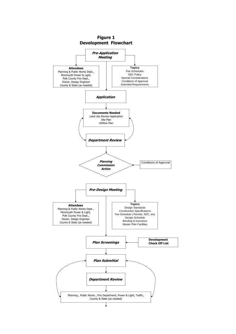
Pre-Application Meeting
AttendeesPlanning & Public Works Dept.,
Monmouth Power & Light,
Polk County Fire Dept.,
Owner, Design Engineer
County & State (as needed)
Documents NeededLand Use Review Application
Site Plan
Utilities Plan
Planning
Commission
Action
Department Review
Figure 1
Development Flowchart
TopicsFee Schedules
SDC PolicySpecial ConsiderationsConditions of Approval
Submittal Requirements
Application
Pre-Design Meeting
TopicsDesign Standards
Construction SpecificationsFee Schedule ( Permits, SDC, etc)
Design ScheduleBonding & Insurance Master Plan Facilities
AttendeesPlanning & Public Works Dept.,
Monmouth Power & Light,
Polk County Fire Dept.,
Owner, Design Engineer
County & State (as needed)
Plan Screenings
Plan Submittal
Department Review
Planning , Public Works , Fire Department, Power & Light, Traffic,
County & State (as needed)
Development
Check Off List
Conditions of Approval
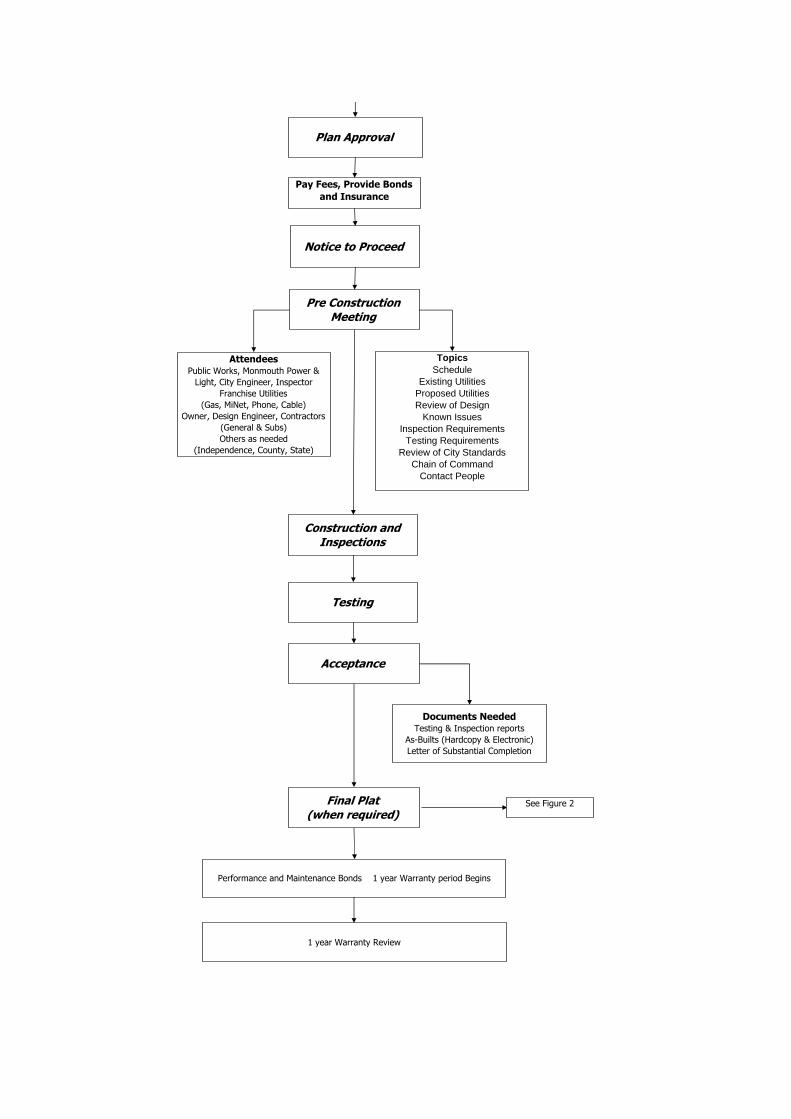
Plan Approval
Pay Fees, Provide Bonds
and Insurance
Notice to Proceed
Pre Construction Meeting
AttendeesPublic Works, Monmouth Power &
Light, City Engineer, Inspector
Franchise Utilities
(Gas, MiNet, Phone, Cable)
Owner, Design Engineer, Contractors
(General & Subs)
Others as needed
(Independence, County, State)
TopicsSchedule
Existing UtilitiesProposed UtilitiesReview of Design
Known IssuesInspection Requirements
Testing RequirementsReview of City Standards
Chain of CommandContact People
Construction and Inspections
Testing
Acceptance
Final Plat(when required)
Performance and Maintenance Bonds 1 year Warranty period Begins
Documents NeededTesting & Inspection reports
As-Builts (Hardcopy & Electronic)
Letter of Substantial Completion
1 year Warranty Review
See Figure 2

DEVELOPMENT CHECK-OFF LISTThe following checked items will be required to
process your application.
Prior to Review
5 Sets of:
Preliminary plat approval
Title SheetMust include vertical control information
General and Special Notes
Overall Site Plan (include area features & utilities within 250'of proposed project)
Street Construction Plans, Profiles, & Details
Stormwater System Plans, Profiles, & Details
Sanitary System Plans, Profiles, & Details
Water System Plans, Profiles, & Details
Existing Grading Plan
Final Grading Plan
Erosion Control Plan
Details
Prior to Notice to Proceed
DEQ Approval (if required)
NPDES 1200 - C Permit (if required)
Soils Report (if required)
Construction Cost Estimate
Payment of Permit Fee
Removal/Fill Permits (if required)

Project Engineer Submits Final Plat
Figure 2
Final Plat Approval Process
Flowchart
Public Works Review & Approval
Planning Department Review & Approval
County Surveyor Review & Approval
Plat Approved & Filed with County Clerk
Monmouth Power & Light Review &
Approval
Appropriate Fees & Taxes Paid
CITY OF MONMOUTH DEPARTMENT OF PUBLIC WORKS
DESIGN STANDARDS
CHAPTER 2
SANITARY SEWER
CITY OF MONMOUTH DEPARTMENT OF PUBLIC WORKS
401 HOGAN ROAD N. MONMOUTH, OREGON 97361
TELEPHONE: (503) 838-2173
FAX: (509) 838-0201
REVISED JANUARY 2008

CITY OF MONMOUTH 2 CHAPTER 2 – SANITARY SEWER DESIGN STANDARDS REV 1/08
TABLE OF CONTENTS
2.00 General Design Considerations ............................................................................3 2.01 Sanitary Sewer System Capacity..........................................................................3 2.02 Sanitary Sewer Requirements ..............................................................................4 2.03 Pipe Materials.......................................................................................................4 2.04 Size.......................................................................................................................4 2.05 Minimum Slope.....................................................................................................4 2.06 Anchor Walls ........................................................................................................6 2.07 Minimum Depth.....................................................................................................6 2.08 Location ................................................................................................................8 2.09 Alignment..............................................................................................................9 2.10 Manholes and Cleanouts ......................................................................................9 2.11 Sewer Service Lines and Private Collection Systems.........................................12

CITY OF MONMOUTH 3 CHAPTER 2 – SANITARY SEWER DESIGN STANDARDS REV 1/08
2.00 General Design Considerations
Sanitary sewers shall be designed to remove the domestic sewage and industrial wastes from basements of houses, commercial or industrial buildings, and all public and private establishments where possible.
Storm water, including street, roof, or footing drainage, shall not be discharged into the sanitary sewer system but shall be removed by a system of storm drains or by some other method separate from the sanitary sewer system.
Unpolluted cooling waters shall not be discharged into sanitary sewers. The overflow drains and filter backwash lines of swimming pools and "hot tubs" shall drain into a sanitary sewer.
In general, sewer systems shall be designed to care for future loads and for ultimate development of the specific drainage area concerned.
As a condition of sewer service, all developments will be required to provide public sewers to serve adjacent upstream parcels in order to provide for an orderly development of the drainage area. This shall include the extension of sewer mains in easements across the property to adjoining properties and across the street frontage of the property to adjoining properties when the main is located in the street right-of-way. This shall include trunk sewers that are oversized to provide capacity for upstream development.
2.01 Sanitary Sewer System Capacity
Design flows shall be determined by using the factors of the Sewer Master Plan in which the development is situated.
In the absence of Master Plan and flow data or other reliable information, the following factors may be assumed:
Per Capita Peak Hourly Flow: 400 gpcd (lateral sewers)�
It is recommended that design calculations include estimates of average maximum and minimum daily flows. The submission of design calculations will not ordinarily be required, but designers should be prepared to substantiate pipe sizes, layout, population estimates, land uses, or other design assumptions.
These factors may be used to estimate the peak daily flow which includes an allowance for infiltration.
�Per capita peak hourly flows are the sum of peaked average daily domestic flows and infiltration inflow. The per capita peak hourly flows for trunk sewers must be computed for each case because of variable peaking factors.

CITY OF MONMOUTH 4 CHAPTER 2 – SANITARY SEWER DESIGN STANDARDS REV 1/08
Design capacity of main and trunk sewers shall be designated on the following basis:
a) Lateral sewers: Design capacity shall be based on sewers flowing one-half (1/2) full.
b) Trunk sewers: Design capacity shall be based on sewers flowing full, without head.
2.02 Sanitary Sewer Requirements
This chapter contains the physical design requirements for public sanitary sewer systems in the city. These design requirements may be used for private systems when plumbing code requirements cannot be met, provided the system is designed and appropriately certified by a professional civil engineer.
2.03 Pipe Materials
Pipe materials shall conform to the Standard Construction Specifications.
2.04 Size
Lateral sewers shall not be less than eight (8) inches inside diameter and shall begin at a manhole and shall terminate at a manhole except as provided in Section 1.10 (b).
2.05 Minimum Slope
a) All sanitary sewers shall be laid on a slope which will produce a mean velocity, when flowing half full of at least two (2) feet per second, which is based upon Manning's pipe friction formula, using a roughness coefficient, valued at not less than 0.013, or the pipe manufacturer's recommendations, whichever is greater. The minimum acceptable slope for various pipe sizes with an "n" value of 0.013 are listed in Table 2.1.

CITY OF MONMOUTH 5 CHAPTER 2 – SANITARY SEWER DESIGN STANDARDS REV 1/08
Table 2.1
Inside Pipe Diameter
(inches)
Percent of Grade (feet per 100 feet)
(private sewers only)
6
0.60 to 0.75
8
0.40
10
0.30
12
0.22
15
0.15
18
0.12
21
0.10
24
0.09
27
(and larger)
0.08
In general, gradients greater than those shown above are desirable and are particularly recommended on the upper ends of lateral sewers.
In theory, new PVC sewers have a manufacturer's "n" value of 0.009; however, sand and grit as well as slime build-up on the pipe walls renders a true "n" value with time of 0.013; hence, an "n" value of less than 0.013 will not be considered for approval.
Engineers are cautioned not to specify sewers of sizes which are obviously larger than is necessary for satisfactory carrying capacity but which are specified in order to meet grade requirements, i.e., a ten-inch pipe for an eight-inch pipe to acquire a decrease in slope.
b) Grades (slopes) shall be determined using the elevation and distance to the center of the manhole. The average between any inlet Slope (Si) and outlet Slope (So) in percent across the manhole shall not exceed 25 percent.
Si + So = less than 25 percent (feet per 100 feet) 2
CITY OF MONMOUTH 6 CHAPTER 2 – SANITARY SEWER DESIGN STANDARDS REV 1/08
c) Generally, a vertical offset in grade exceeding twenty-five hundredths (0.25) of a foot will not be permitted. Exceptions will be the following:
(i) When a smaller diameter connects to a larger diameter sewer. (The guidance is to match the crown elevation.)
(ii) When a grade conflict exists with an existing utility, the maximum vertical drop may be one (1) foot or as approved. (This is intended to provide flexibility of design only where the standard general rule of 0.25 maximum cannot be applied. The designer may offset the elevations up to one foot without prior approval, but only in those cases where the utility conflicts cannot be avoided. It is not intended to be the standard practice).
(iii) When a vertical drop greater than two (2) feet is approved, an outside drop must be installed as per standard plans.
The intent is to maintain accessibility to TV camera equipment.
2.06 Anchor Walls
Sewers on slopes of 20 percent or more shall be secured by anchor walls in accordance with standard plans.
Where velocities greater than fifteen (15) feet per second are attained, the pipe material shall be ductile iron and special provision shall be made to protect manholes against erosion and displacement by shock. This may be accomplished by installing one additional manhole to decrease the slope or to split a 90° horizontal direction change into two (2) 45° increm ental changes.
2.07 Minimum Depth
All sanitary sewers shall be laid at a depth sufficient to drain building sewers, to protect against damage by frost or traffic, and to drain basement sewers where practical. Sufficient depth shall mean the minimum cover from the top of the pipe to finish grade at the sewer alignment.
Under normal conditions, sanitary sewers in residential areas shall be placed in the street with the following minimum cover:
Lateral Sewer - Six (6) feet
Trunk Sewer: in the roadway - Eight (8) feet in easements - Eight (8) feet
Where the topography is relatively flat and existing sewers are shallow (five (5) feet or less), the minimum cover may be three (3) feet. Less than three (3) feet of cover

CITY OF MONMOUTH 7 CHAPTER 2 – SANITARY SEWER DESIGN STANDARDS REV 1/08
will require the installation of ductile iron pipe. See Table 2.2 for class of pipe required.
In a new designated residential hillside subdivision, mainline and lateral sewers shall be placed in the street at a depth sufficient to drain building sewers on the low side of the street.
Deviation from the above standards will be considered on a case-by-case basis when one of the following circumstances exists and the required documentation is submitted:
a) Underlying rock strata required: A request in writing to the Director together with a soils report including a plan and profile certifying bed rock exists three (3) feet below the undisturbed ground surface at all investigated alignments.
b) A ditch or stream must be crossed required: A plan and profile; horizontal scale 1" = 20', vertical scale 1" = 2'.
Table No. 2.2
Pipe Class Requirement (Sewer less than 3' of Cover)
Pipe Size (In.)
Depth of
Cover (Ft.)
In Fills Use D.I. Class
Standard Trench Use D.I. Class
4
(Service Lines)
0.5 1.0 1.5 2.0
51 51 51 51
51 51 51 51
6
(Service Lines)
0.5 1.0 1.5 2.0
53 51 50 50
50 50 50 50
8
0.5 1.0 1.5 2.0
54 52 50 50
50 50 50 50

CITY OF MONMOUTH 8 CHAPTER 2 – SANITARY SEWER DESIGN STANDARDS REV 1/08
2.08 Location
a) Relation to Water Lines and Other Utilities
Sanitary sewers shall be separated from water pipes and sources of domestic water in accordance with OAR Chapter 333.
b) Sewers in Streets or Easements
Unless approved by the Director, sewers shall be located in the street right-of-way within five (5) feet of the street centerline on the low side of the street. Sewers in easements will be allowed only after all reasonable attempts to place the mains in the right-of-way have been exhausted. All easement installations must be approved by the Director on a case-by-case basis. If streets have curved alignments, the center of the manhole shall not be less than six (6) feet from the curb face on the outside of the curve nor the sewer centerline less than six (6) feet from the curb face on the inside of the curve. The intent is to prevent a conflict with new storm drain lines while still providing for the least number of manholes required to traverse a curve.
When it is approved by the Director to locate sewers in easements, the sewer shall be centered in the easement and the conditions of the easement shall be such that the easement shall not be used for any purpose which would interfere with the unrestricted use for sewer main purposes. Under no circumstances shall a building or structure, tree, or fence be placed over a sanitary sewer main or sewer easement. This shall include overhanging structures with footings located outside the easement. All manholes within easements and pipelines over 24-inch diameter regardless of location shall have lock down lids.
Easements for sewers less than 12 inches in diameter shall have a minimum width of ten (10) feet. Sewers 12 to 15 inches in diameter shall have a minimum easement width of 15 feet, and sewers greater than 15 inches in diameter, shall have a minimum easement width of 20 feet.
Easement locations for public sewer mains serving a PUD, apartment complex, or commercial/industrial development shall be in parking lots, private drives, or similar open areas which will permit an unobstructed vehicle access for maintenance by City forces.
Sewers with more than six (6) feet of cover and/or inside diameters 24 inches or greater will require wider easements. A slope of one horizontal to one vertical from the sewer invert to ground surface will be used in determining easement width. Easement widths shall vary from the ten (10) foot minimum by five (5) foot increments, i.e., 10, 15, 20 feet, etc.
Common placement in the easement of sewer and storm drain line may be allowed under certain conditions subject to approval by the Director.

CITY OF MONMOUTH 9 CHAPTER 2 – SANITARY SEWER DESIGN STANDARDS REV 1/08
Common easements will be reviewed on a case-by-case basis. Separation of utilities must meet Oregon State Department of Environmental Quality (DEQ) requirements.
All easements must be furnished to the City for review and approval prior to recording.
c) Relation to Streams and Drainage Channels
Generally, the top of all sanitary sewers entering or crossing streams shall be at a sufficient depth below the natural bottom of the streambed to protect the sewer line. One (1) foot of cover is required where the sewer is in rock, three (3) feet of cover is required in other materials. In paved channels, the top of the sewer line shall be placed at least six (6) inches below finish grade of the bottom of the channel, except as provided above.
Sewers located along streams shall be located outside of the streambed and sufficiently removed therefrom to provide for future possible stream channel widening. All manhole covers shall be leakproof at or below the 100-year flood elevation.
Sewers crossing streams or drainage channels shall be designed to cross the stream as nearly perpendicular to the stream channel as possible and shall be free from change of grade.
Pipe material shall be ductile iron Class 50 with an 18-foot length of pipe centered on the stream or drainage channel centerline. The ductile iron pipe shall extend to a point where a one-to-one slope, that begins at the top of the bank and slopes down from the bank away from the channel centerline, intersects the top of the pipe.
Concrete encasement will be required when the above cover requirements cannot be met. Each deviation from the above requirements will be reviewed on a case-by-case basis.
2.09 Alignment
Sewer lines shall be laid on a straight alignment and uniform slope between consecutive manholes.
Horizontal and vertical curves in sanitary sewers are not permitted.
2.10 Manholes and Cleanouts
a) Cleanouts
Cleanouts will not be approved as substitutes for manholes, except at the upper end of lateral or main sewers that will be extended on the same grade

CITY OF MONMOUTH 10 CHAPTER 2 – SANITARY SEWER DESIGN STANDARDS REV 1/08
and alignment during the next construction phase. All cleanouts will be considered on a case-by-case basis and approved by the Director of Public Works.
b) Manhole Taps
When an existing manhole is tapped to install a new sewer which will drain into the manhole, the new sewer shall enter the manhole with the invert a minimum 0.25 feet below the shelf elevation of the manhole and a channel shall be formed in the shelf of the manhole to the invert of the existing sewer.
c) Manhole Location
Manholes shall be placed at the following locations:
(i) Every change in grade (grade break) or alignment of a sewer.
(ii) Every point where there is a change in size or abrupt change in invert elevation (drop) change of a sewer.
(iii) Each intersection or junction of a sewer.
(iv) Upper end of all lateral sewers, except as provided in (b) above.
A) Adjacent to the radius point of a cul-de-sac which has three (3) or more parcels of land fronting on the cul-de-sac.
B) In front of the last property or lot being served, ten (10) feet past the common lot line of the adjoining parcel served.
(v) At intervals of 400 feet or less. Deviation from this requirement shall be reviewed on a case-by-case basis for approval, considering whether or not flushing and cleaning equipment can adequately service the proposed sewer line.
(vi) At any point where a service or private sewer of 8 inches or larger intersects a sewer main.
Manholes shall not be located in the curb or in the gutter. Placement of manholes behind the curb shall be reviewed on a case-by-case basis for approval. Consideration shall be given to those sewer lines which already exist behind the curb.
Two (2) manholes shall be installed when the horizontal deflection angle between a lateral or main connection to an existing sewer is less than or equal to 75°. Spacing of such manholes shall be a m inimum of ten (10) feet outside to outside.

CITY OF MONMOUTH 11 CHAPTER 2 – SANITARY SEWER DESIGN STANDARDS REV 1/08
The intent is to prevent a new lateral sewer connection from discharging into an existing sewer opposing the existing flow.
Where practical, manholes shall be located at street intersections. All manholes from which future sewer line extensions are anticipated, shall have a pipe stub designed and installed at the grade and direction of the anticipated sewer main extension. Pipe stubs shall be a minimum of eight (8) inches in size and shall protrude at least one (1) foot outside of the manhole base.
Risers shall be used to bring casting to grade. Combined riser sections shall not exceed six inches in height between cone and casting.
d) Drop Manholes
Outside drop assemblies shall be provided for pipe lines 12 inches in diameter and smaller when entering a manhole at a distance of more than 24 inches above the invert of the outlet line. The vertical displacement shall be measured at the inside manhole walls and not the manhole centerline. Larger pipe lines shall be introduced into the manhole at the manhole invert.
SPECIAL NOTE: Drop manholes shall only be used in extreme cases of slope difference between existing and proposed sewer lines or when very special conditions exist such as a conflict with existing facilities which cannot be relocated.
Approval of the Director after review of the plans by appropriate design, construction, and maintenance sections is required to construct a drop manhole.
e) Drop Across the Structure
The drop across the structure shall normally be one-tenth (0.10) of a foot. Where there is to be more than 60° of horizontal de flection angle between any inlet and outlet line of a structure, the vertical drop from said inlet and outlet line of a structure shall be at least two-tenths (0.20) of a foot.
Maximum drop across the structure shall be limited to one (1) foot.
f) Metering Manhole
A metering manhole shall be installed on all systems meeting one of the following criteria:
(i) A private sewer which contributes more than 10,000 gallons per day to the public sewer.

CITY OF MONMOUTH 12 CHAPTER 2 – SANITARY SEWER DESIGN STANDARDS REV 1/08
(ii) A private sewer which serves more than one structure on the same premises,
g) Other Requirements
Manholes and wet wells over 20 feet in depth or with pipes over 36 inches in diameter shall have structurally sound grated working platforms (nonmetallic covered) for maintenance and fall protection, spaced not greater than 15 feet apart.
Pipelines 36 inches and larger in diameter shall have manhole openings of 30 inches in diameter.
Where manhole rims are 2 feet or greater above grade or finished ground, the manhole lids shall be made of aluminum.
2.11 Sewer Service Lines and Private Collection Systems
a) Sewer Service Lines
Sewer service lines are those portions of the sewage system between the public sewer and the structure being served, which are installed and maintained by property owners or agencies other than the City.
As a minimum criterion, construction of the house or building sewer service line shall be of the same quality and meet the same requirements as the public sewer with regard to materials, watertightness, and location. In addition, these sewers shall conform to the State and local plumbing codes and restrictions. No roof, surface, foundation, or stormwater drain lines shall be connected to the public sewers.
Sewer service lines shall not tie into an existing manhole except in special cases approved by the Director of Public Works. Exception: Services may tie into a manhole which is located in a cul-de-sac provided the line is not planned to be extended in the future. A cleanout shall be installed at the property line when the building sewer is connected to the sewer service line. For long sewer service lines in existing residential areas, a cleanout shall be installed at property line and at 100-foot intervals thereafter. Sewer service lines shall have at least four (4) feet of cover at the property line. Generally, the topography of the property will dictate how deep the service line must be.
Each individual building site shall be connected by a separate sewer service line connected to the public or private main sewer. Combined sewer service lines will be permitted only when the property cannot legally be further divided. An example of this is a residential lot with a house and unattached garage or shop with plumbing facilities.
CITY OF MONMOUTH 13 CHAPTER 2 – SANITARY SEWER DESIGN STANDARDS REV 1/08
The minimum inside diameter of a sewer service line shall be four (4) inches and shall be equal to or greater than the building plumbing stub (building drain) diameter. The minimum inside diameter of sewer service lines to serve multifamily dwellings or commercial buildings shall be six (6) inches. Fixture unit equivalents shall be determined in accordance with Chapter 4 of the Uniform Plumbing Code and the Oregon State Plumbing Specialty Code (Table 4-1).
Minimum sizes and slopes for sewer services, based on the fixture unit equivalents, shall be in accordance with the Uniform Plumbing Code Table 11-2.
Sewer service lines for townhouses and similar cluster housing developments shall be installed on a uniform slope from the main line sewer connection to a point five (5) feet from the end of the building drain conforming to the above requirements.
A backwater check valve shall be installed when the lowest floor level of a house to be connected to the public sewer is below a point which is 12 inches above the top of the nearest upstream manhole or cleanout structure. A gate valve in addition to the required backwater check valve is optional but should be considered for installation for additional protection should the backwater valve fail or become clogged with debris.
b) Private Collection System
Private collection system sewers shall be designed in conformance with main line standards specified in this chapter when plumbing code grade requirements of U.P.C. Section 1106 cannot be met. Subsection (a) of this section must be used for sewer service lines in the system with the following exceptions:
(i) The minimum size sewer line upstream of the metering manhole structure shall be six (6) inches.
(ii) A manhole is required at the connection to the City main.
(iii) A metering manhole is required at the property line upstream from the manhole connection at the City main required by (2) above.
The metering manhole shall consist of a standard manhole with the inlet pipeline invert placed 0.4 foot above the outlet invert. The inlet pipe shall extend one (1) foot past the manhole wall and shall be cut in half six inches from the outfall end and the top half of the pipe removed. The channel shall be formed from the outfall end to the outlet line in the usual manner.
The intent is to provide a half round section of pipe inside the manhole into which City personnel can place flow monitoring equipment.

CITY OF MONMOUTH 14 CHAPTER 2 – SANITARY SEWER DESIGN STANDARDS REV 1/08
c) Locating Building Sewers and Private Collection Systems
All sewer piping shall have an electrically conductive tracer wire, 18 gauge minimum size, insulated copper, and green sheeting, installed in the trench for the purpose of locating pipe in the future. The tracer wire shall run the full length of the installed pipe, with one end located around the mainline or lateral. The other end of the tracer wire shall be of sufficient length for an electrically conductive splice.

CITY OF MONMOUTH DEPARTMENT OF PUBLIC WORKS
DESIGN STANDARDS
CHAPTER 3
STREETS
CITY OF MONMOUTH DEPARTMENT OF PUBLIC WORKS
401 HOGAN ROAD N. MONMOUTH, OREGON 97361
TELEPHONE: (503) 838-2173
FAX: (509) 838-0201
REVISED JANUARY 2008
CITY OF MONMOUTH 2 CHAPTER 3 – STREETS DESIGN STANDARDS REV 1/08
TABLE OF CONTENTS
3.00 General Design Considerations.............................................................................3 3.01 Local Street Design ..............................................................................................3 3.02 Miscellaneous Design Standards .........................................................................4 3.03 Street Right-Of-Way and Curb-To-Curb Widths ...................................................5 3.04 Design Speeds .....................................................................................................5 3.05 Horizontal, Vertical Curves, and Superelevation ..................................................5 3.06 Grades..................................................................................................................6 3.07 Portland Cement Concrete Street Design and Construction.................................7 3.08 Asphaltic Concrete Street Construction ................................................................7 3.09 Alley Construction.................................................................................................7 3.10 Portland Cement Concrete Curbs – Type and Application ...................................7 3.11 Sidewalk Construction and Location.....................................................................8 3.12 Bicycle and Wheelchair Ramps ............................................................................8 3.13 Street Lighting ......................................................................................................9 3.14 Private Driveways and Parking Lots .....................................................................9

CITY OF MONMOUTH 3 CHAPTER 3 – STREETS DESIGN STANDARDS REV 1/08
3.00 General Design Considerations
Street improvements including curbs, sidewalks and storm drainage shall be provided on all property developed within the City of Monmouth according to these standards for the following types of development:
a) All major partitions and subdivisions.
b) All minor partitions that fall within one or more of the following conditions:
(i) Where the land is zoned MX (Mixed Density Residential); RM (Medium Density Residential); RH (High Density Residential); MS (Main Street); CO (Commercial Office); CR (Commercial Retail); CRT (Commercial Retail Transitional); CH (Commercial Highway); IP (Industrial Park); IL (Light Industrial); PS (Public Services); PSC (Public Services College).
(ii) Located on a designated arterial or collector street.
(iii) Where 40 percent of the street frontage within 200 feet of the boundaries of the partitioned property has already been paved and curbed.
(iv) Where the abutting street is complete with curbs opposite the partitioning.
3.01 Local Street Design
The following elements should be incorporated in the design of the local residential street system to discourage and minimize both the volume and impact of through traffic within residential neighborhoods or subdivisions:
a) Use of T-intersections
b) Use of loop streets
c) Curvilinear street pattern
Employment of the above design elements will provide some degree of travel discontinuity, thus discouraging the use of the residential street system as through routes. In addition, excessive speed within the neighborhood may also be minimized.
For the above design alternatives to work properly in minimizing neighborhood infiltration, it is necessary to plan for and provide the collector and arterial network by which through traffic can travel. Care should be taken in the design of the local

CITY OF MONMOUTH 4 CHAPTER 3 – STREETS DESIGN STANDARDS REV 1/08
street network to ensure that connections with the collector and arterial streets are adequate.
3.02 Miscellaneous Design Standards
a) Cul-de-sac Turnarounds
Cul-de-sac turnarounds on residential streets in subdivisions, mini-subdivisions or on hillside streets shall be designed and constructed according to the following specifications.
Subdivision 40 foot paved radius 57 foot right-of-way radius
Mini-Subdivision 40 foot paved radius 57 foot right-of-way radius
Hillside Streets Over 400 feet 40 foot paved radius 57 foot right-of-way radius
Cul-de-sacs in industrial developments shall provide adequate turnarounds for the type of vehicles served by the streets.
b) Private Streets
All private street cross-sections shall be designed according to City of Monmouth street standards except where approved by the Director of Public Works.
c) Catch Basins
Catch basins shall be designed according to City of Monmouth Storm Drainage Standards.
d) Manhole Cover and Water Valve Adjustments
Manhole covers and water valves shall be adjusted to finish grade of the improved street.
e) Brick Crosswalks/Sidewalks or Alternate Designs
Brick crosswalks/sidewalks or alternate designs are discouraged. If proposed, they shall be submitted by a professional engineer and are subject to the review and approval of the Director of Public Works.
CITY OF MONMOUTH 5 CHAPTER 3 – STREETS DESIGN STANDARDS REV 1/08
f) Street Reconstruction
Whenever a street is reconstructed on a new grade or alignment such that the new street section is built over the existing street, the existing pavement shall be broken up and removed. Alternatively, if any of the existing pavement is to be used within the base of the new street section, it shall be broken up, reprocessed, and compacted such that it is comparable in gradation to the aggregate required for the new base rock.
3.03 Street Right-Of-Way and Curb-To-Curb Widths
The street right-of-way and curb-to-curb widths for a given street shall reflect the designated widths of that particular classification of street (see Table 3 – 1 included at the end of this chapter).
3.04 Design Speeds
The minimum design speeds for classified streets shall be as follows:
a) Residential Streets 30 mph
b) Collectors 35 mph
c) Arterials 45 mph
Design considerations for all street geometrics shall reflect these design speeds. Variance from these design speeds shall be approved by the Director of Public Works.
3.05 Horizontal, Vertical Curves, and Superelevation
Horizontal and vertical curves for a given street shall reflect the design speed of the particular classification of the street.
The 1993 AASHTO Policy on Geometric Design of Highways and Streets shall serve as the guideline for the design of horizontal and vertical curves on City streets. The maximum superelevation rate permitted on City streets shall be six percent for arterials and four percent for collectors.
Sharp horizontal curvature should not be introduced at or near the top of a pronounced crest vertical curve. Similarly, sharp horizontal curvature should not be introduced at or near the low point of a pronounced sag vertical curve.
Minimum stopping sight distance shall be provided on all vertical curves.

CITY OF MONMOUTH 6 CHAPTER 3 – STREETS DESIGN STANDARDS REV 1/08
Vertical curves shall be parabolic and of a minimum length computed from the formula:
L=KA where:
L = length of vertical curve in feet K = design constant (rate of vertical curvature) A = algebraic difference in grades, percent
K is a constant for each design speed; its selection for crest vertical curves is based on sight distance requirements and, for sag vertical curves, on headlight sight distance. K values to be used for the design of vertical curves are as follows:
Vertical Curves K Values
Design Crest V.C. Sag V.C. Speed MPH
S.S.D. Minimum
Maximum
S.S.D. Minimum
Maximum
20 10 20 25 20 25 30 30 30 35 35 35 40 50 45 50 40 60 80 55 70 45 80 120 70 90 50 110 160 85 110 60 190 310 120 160
3.06 Grades
Maximum grade on streets shall be as follows:
a) Arterials .06 ft/ft (6%)
b) Collectors .08 ft/ft (8%)
c) Residential .12 ft/ft (12%)
No street grade shall exceed (12%) without a variance.
Maximum grade for local or residential streets in hillside areas shall not exceed .12 ft/ft (12%).
The minimum gutter grade permitted shall be 0.25 feet per 100 feet (0.25 percent grade).
On curve radii of 30 feet or less, a minimum grade of 0.5 percent shall be required.
For cross-slope design standards see City of Monmouth Standard Drawings.
CITY OF MONMOUTH 7 CHAPTER 3 – STREETS DESIGN STANDARDS REV 1/08
3.07 Portland Cement Concrete Street Design and Construction
In general, Portland Cement Concrete design and construction, when permitted by City, shall conform to Portland Cement Association (PCA) specifications.
3.08 Asphaltic Concrete Street Construction
CITY OF MONMOUTH (FLEXIBLE PAVEMENT STRUCTURE DESIGN)
Flexible pavement design shall conform to the APAO Asphalt Pavement Design Guide.
All testing shall be conducted by certified testing laboratory acceptable to the Director.
The engineer will be required to submit pavement structure design data for any street for which the Director has reason to suspect unsuitable soil conditions, high percentage of trucks or any other conditions that may significantly affect the pavement structure design.
FOR STREET CLASSIFICATION (LOCAL, COLLECTOR, ARTERIAL) SEE MONMOUTH TRANSPORTATION PLAN.
3.09 Alley Construction
a) Alley width and improvement requirements shall comply with the City of Monmouth Standard Drawings.
b) All alleys shall be constructed of Portland Concrete Cement.
c) All alley improvements shall require a one-foot clearance strip between the edge of alley and right-of-way line except for alleys ten-feet wide or less. In this the case the clearance strip shall be six-inches in width.
3.10 Portland Cement Concrete Curbs – Type and Application (See Standard Drawing No. 303)
a) In general, type "A" curb and gutter shall be installed on all new construction or reconstruction to control drainage from sheet flow across the street, to preserve curb exposure during subsequent overlays, and to eliminate cracking new curbs during the street paving operation.
The minimum gutter grade permitted shall be 0.25 feet per 100 feet (0.25 percent grade)
(i) Rolled Curb may be used in urban developments on private streets only.
(ii) Type "C" curb shall be used for edges of traffic islands only.

CITY OF MONMOUTH 8 CHAPTER 3 – STREETS DESIGN STANDARDS REV 1/08
b) A six (6) inch curb exposure is normally required on residential streets. A seven (7) inch curb exposure is required on all major streets.
c) Two curb weeps, three (3) inches in diameter, shall be provided for each lot.
d) Minimum curb radii required at intersections shall be as follows:
Intersection Radius
Residential to Residential 20 feet Residential to Collector or Arterial 25 feet Collector to Collector or Arterial 30 feet Arterial to Arterial 30 feet
3.11 Sidewalk Construction and Location
a) A sidewalk shall be constructed on all streets. Location and width of sidewalks shall be as prescribed in City of Monmouth Title IX Zoning and Development Ordinance.
Curbline sidewalks are required in residential areas unless otherwise approved by the Director.
Midblock walks that are required on subdivisions shall be constructed as part of the subdivision development. Midblock walks shall be eight feet in width on a ten foot easement.
b) Sidewalks shall be constructed of Portland Cement Concrete, capable of meeting a compressive strength of 3,000 PSI after 28 days.
c) When sidewalks are to be constructed they shall be of a minimum width of five feet.
d) Refer to City of Monmouth Zoning and Development Ordinance for Specific Sidewalk Code, and Maintenance Standards.
3.12 Bicycle and Wheelchair Ramps
a) Under Chapter 31, Handicap Access, of the Uniform Building Code of the State of Oregon it is required that access be available to the handicapped for use of public facilities. It is the City's intent that wheelchair ramps be provided at all intersections. In addition, all ramps shall conform to requirements of the Americans with Disabilities Act and the requirements contained herein.
b) The City of Monmouth, Department of Public Works Standard Construction Drawing No. 307 indicates various conditions for ramp requirements within the city.

CITY OF MONMOUTH 9 CHAPTER 3 – STREETS DESIGN STANDARDS REV 1/08
c) Ramps shall be located to avoid catchbasins or catchbasins shall be relocated.
d) In situations where a sidewalk ramp is being retrofitted to an existing curb, the Project Engineer shall obtain sufficient survey elevations at the ramp locations to determine the curb grades and analyze the drainage. Engineer shall show on the plans the extent of the existing curb and sidewalk to be replaced. Type A curb and gutter shall be required where the gutter grade in either direction is less than or equal to 2 percent. The curb and gutter shall be designed to carry drainage away from the ramp; and the gutter grade at no place within 5 feet of the sidewalk ramp will be less than 0.50 percent.
e) Where a new curb is being constructed as part of a street improvement project (as opposed to retrofit) the curb grade within 5 feet of the sidewalk ramp will at no place be less than 0.50 percent grade.
3.13 Street Lighting
Coordinate Street Lighting Design with Monmouth Power & Light Street Lighting Standards.
3.14 Private Driveways and Parking Lots
a) Surfacing and Construction
Driveways in this section will refer to that area between the property line and parking area.
All private driveways and parking lots shall be paved with asphalt or concrete. The type and quantity of materials for construction is based upon the type of vehicular use and is shown below:
(i) Residential, Light Commercial/Retail (majority passenger vehicles)
Initial Construction
Asphalt concrete and crushed aggregate Asphalt concrete (class "B") 2-1/2 inch 1 inch crushed aggregate base 6 inch
Full depth asphalt concrete Asphalt concrete (Class "B") 2 inch Bituminous base 3 inch

CITY OF MONMOUTH 10 CHAPTER 3 – STREETS DESIGN STANDARDS REV 1/08
(ii) Heavy Commercial/Retail (high volume of large and heavy delivery vehicles)
Initial Construction
Asphalt concrete and crushed aggregate Asphalt concrete (class "B") 2-1/2 inch 1 inch crushed aggregate base 9 inch
Full depth asphalt concrete Asphalt concrete (Class "B") 2 inch Bituminous base 4 inch
(iii) Light Industrial
(iv) Initial Construction
Asphalt concrete and crushed aggregate Asphalt concrete (class "B") 2-1/2 inch 1 inch crushed aggregate base 11-1/2 inch
Full depth asphalt concrete Asphalt concrete (Class "B") 2 inch Bituminous base 7-1/2 inch
(v) Heavy Industrial
Initial Construction
Asphalt concrete and crushed aggregate Asphalt concrete (class "B") 2-1/2 inch 1 inch crushed aggregate base 13-1/2 inch
Full depth asphalt concrete Asphalt concrete (Class "B") 2 inch Bituminous base 8 inch
Bumper guards or wheel barriers shall be installed so that no portion of a vehicle projects into the right-of-way or over the adjoining property. The area between the wheel barriers or bumper guards shall be paved or covered with evergreen ground cover.
Driveways shall maintain adequate drainage facilities to prevent water ponding and ice formation. Permanent drainage facilities shall be provided for parking lots in all commercial, industrial, and multifamily developments creating new impervious surfaces of greater than 3,000 square feet in an area within any 12-month period. These standards are intended to fulfill the

CITY OF MONMOUTH 11 CHAPTER 3 – STREETS DESIGN STANDARDS REV 1/08
requirements of Section 1406, "Special Storm Sewers," of the Uniform Plumbing Code for private storm drains.
b) Driveway Widths (area between property line and parking area)
(i) The minimum driveway widths are reflected in the type of use and parking served by that particular driveway as shown below:
Minimum Driveway Widths
Type of Use and Parking Served Minimum Width
Dwellings: One parking space 10 feet Two parking spaces 16 feet Three or more parking spaces 22 feet All other uses: One-way driveway, no parking in driveway 12 feet Two-way driveway, no parking in driveway 22 feet Additional width for any side of any driveway where parking is allowed 8 feet
(ii) The maximum driveway widths are reflected in the type of use served by that particular driveway as shown below:
Maximum Driveway Widths
Type of Use and Parking Served Maximum Width
Residential Driveways: Single parking space 15 feet Two parking spaces 24 feet Three or more parking spaces 36 feet Commercial Driveways: One-way traffic 20 feet Two-way traffic 40 feet
c) Driveways Location
(i) Driveway Locations in General
A) One-way driveways shall be no closer than 75 feet between their nearest edges.
B) Corner properties of less than 75 feet frontage on a major street shall have no driveway located on a major street.

CITY OF MONMOUTH 12 CHAPTER 3 – STREETS DESIGN STANDARDS REV 1/08
C) All proposed commercial businesses shall be limited to one two-way driveway or two one-way driveways per roadway frontage.
D) Any variations from these standards shall be approved by the Director of Public Works.
(ii) Location of Driveways Within the Central Business District
For the central business district, driveways from commercial businesses or multifamily residential units onto a major street shall be located as follows:
A) For major one-way street, 42 feet or less width curb to curb:
1. Driveways for entrance only shall be located at least 50 feet from the downstream intersection and no closer than 100 feet from an upstream intersection;
2. Driveways for exit only shall be located at least 100 feet from the downstream intersection and shall be no closer than 50 feet from an upstream intersection;
3. Two-way driveways shall be located at least 100 feet from either downstream or upstream intersections.
B) For major one-way streets greater than 42 feet curb to curb width:
1. Driveways for entrance only shall be located at least 50 feet from the downstream intersection and no closer than 100 feet from the upstream intersection;
2. Driveways for exit only shall be located at least 150 feet from the downstream intersection and shall be no closer than 50 feet from an upstream intersection;
3. Two-way driveways shall be located at least 150 feet from either downstream or upstream intersections.
C) For major two-way streets:
1. Driveways for entrance only shall be located at least 100 feet from a downstream intersection and no closer than 50 feet from an upstream intersection;

CITY OF MONMOUTH 13 CHAPTER 3 – STREETS DESIGN STANDARDS REV 1/08
2. Driveways for exit only shall be located at least 100 feet from an upstream intersection and at least 50 feet from a downstream intersection;
3. Two-way driveways shall be located at least 100 feet from either the downstream or upstream intersection.
(iii) Location of Driveways Outside of the Central Business District
For all areas outside of the central business district, driveways from commercial businesses or multifamily residential units onto a major street shall be located as follows:
A) For major one-way streets 42 feet or less curb to curb width:
1. Driveways for entrance only shall be located at least 50 feet from the downstream intersection and no closer than 100 feet from an upstream intersection;
2. Driveways for exit only shall be located at least 125 feet from the downstream intersection and no closer than 75 feet from an upstream intersection;
3. Two-way driveways shall be located at least 125 feet from the downstream intersection and no closer than 100 feet from an upstream intersection.
4. In locating multiple driveways the UGM Standards shall be used as a guideline.
B) For major one-way streets greater than 42 feet curb-to-curb width:
1. Driveways for entrance only shall be located at least 50 feet from the downstream intersection and no closer than 125 feet from an upstream intersection;
2. Driveways for exit only shall be located at least 150 feet from the downstream intersection and no closer than 75 feet from an upstream intersection;
3. Two-way driveways shall be located at least 150 feet from either the downstream or upstream intersection.

CITY OF MONMOUTH 14 CHAPTER 3 – STREETS DESIGN STANDARDS REV 1/08
C) For major two-way streets:
1. Driveways for entrance only shall be located at least 125 feet from the downstream intersection and no closer than 75 feet from an upstream intersection;
2. Driveways for exit only shall be located at least 75 feet from the downstream intersection and no closer than 125 feet from an upstream intersection;
3. Two-way driveways shall be located at least 125 feet from either the downstream or upstream intersection.
d) Turnarounds
Should the length of a residential driveway be greater than 50 feet in length and the driveway has only one access to the street or does not loop to the street, a turnaround shall be provided. The minimum inside radius of that turnaround shall be 15 feet and the width at that point (turnaround) shall be 30 feet for maneuvering.
e) Driveway Grades
Driveway grades shall not exceed 12 percent (curbline to parking area) unless the developed parcel is classified as a hillside lot in accordance with SRC 130.400. The Director of Public Works may permit a driveway slope to 20 percent providing no slope exceeds 25 percent between any two points in the driveway.
f) Parking Dimensions and Layout
For two-way circulation the minimum aisle width shall be 20 feet, adequate ingress, egress, and turnaround space shall be provided.
No portion of a parking space or aisle shall be located in a required landscaped yard.
*8'6" stall width shall apply only within parking structures of two or more stories.
Standard size parking stall shall be 9 feet by 19 feet. Small car only parking stall shall be 8 feet by 15 feet.
Curves and corners within the parking facilities shall have a minimum inside radius of 15 feet.
Where landscaping, fences, or walls are to be incorporated into the parking lot design or adjacent to the driveway, the vegetation or physical obstructions shall not restrict the sight distance of the motorists within the parking facility or at the driveway (a ten foot by ten foot vision clearance triangle shall be maintained).

CITY OF MONMOUTH DEPARTMENT OF PUBLIC WORKS
DESIGN STANDARDS
CHAPTER 4
STORMWATER
STORMWATER COLLECTION AND MANAGEMENT SYSTEM
CITY OF MONMOUTH DEPARTMENT OF PUBLIC WORKS
401 HOGAN ROAD N. MONMOUTH, OREGON 97361
TELEPHONE: (503) 838-2173
FAX: (509) 838-0201
REVISED JANUARY 2008
CITY OF MONMOUTH STORMWATER DESIGN STANDARDS REV1/08
2
TABLE OF CONTENTS
SECTION 1 - GENERAL.....................................................................................................3 1.00 Purpose ................................................................................................................3 1.01 Applicability...........................................................................................................3 1.02 General Design Considerations ............................................................................4
SECTION 2 - STORMWATER QUALITY............................................................................6 2.00 General.................................................................................................................6
SECTION 3 - STORMWATER QUANTITY.........................................................................7 3.00 Runoff Calculations...............................................................................................7 3.01 General Detention Requirements .......................................................................10 3.02 Detention Volume Calculations...........................................................................13 3.03 Parking Lot Ponds ..............................................................................................14 3.04 Surface Ponds Other than Parking Lot Ponds ....................................................15 3.05 Closed Detention Systems .................................................................................17
SECTION 4 - OUTFALL DESIGN .....................................................................................18 4.00 General Requirements........................................................................................18 4.01 Outfalls to Open Channel Waterways.................................................................18
SECTION 5 - CONVEYANCE SYSTEM DESIGN ............................................................20 5.00 General Conditions .............................................................................................20 5.01 Capacity..............................................................................................................21 5.02 Piped Systems....................................................................................................22 5.03 Open Channel Drainage .....................................................................................27
LIST OF TABLES Table 1: Runoff Coefficient “C” ………………………………...…………………….……....... 8 Table 2: Manning’s Roughness Coefficients for Overland Sheet Flow ……….…...……...10 Table 3: Waterway Classifications ..……………………………………………….…….........20 Table 4: Design Storm……………………………………………………………...…….……..21 Table 5: Minimum Pipe Grade for Storm Sewers with n= 0.013…………………….…….. 22 Table 6: Manning’s Roughness Coefficients for Existing Pipes…………………….………23 Table 7: Manning’s Roughness Coefficients for Open Channels ……………….…………28
LIST OF FIGURES Figure 1: Rainfall Intensity – Duration – Frequency Curves…………………………..….… 9 Figure 2: Average Velocity of Shallow Concentrated Flow…………………………………11 Figure 3: Size of Stone that will resist displacement for Various Velocities and Side
Slopes…………………………………………………………………………………19

CITY OF MONMOUTH STORMWATER DESIGN STANDARDS REV1/08
3
SECTION 1 - GENERAL
1.00 Purpose
The purpose of these Standards is to provide uniformity under which storm drains within the City may be designed, constructed, and maintained. The objectives of these Standards include, but are not limited to, the following:
a) Protect the safety and security of persons and property by safely conveying all volumes of water from sources upstream to approved storm facilities downstream and preventing the uncontrolled or irresponsible discharge of stormwater onto adjoining public or private property.
b) Maintain and improve the water quality in and the beneficial uses of Monmouth’s urban waterways, lakes, wetlands, and other natural drainage resources.
c) Establish a stormwater detention program consisting of regional and local facilities.
d) Minimize erosion through control of sediment, vegetation removal, and grading. Protect Monmouth’s natural resources by preserving stormwater quality and preventing erosion.
e) Construct facilities which are safe and economical to maintain and which maximize practical design life.
f) Provide for orderly development by creating points of disposal and adequate capacity for future development upstream.
g) Substantially maintain the runoff characteristics of the original undeveloped drainage basin.
1.01 Applicability
All private storm drains outside the building envelope shall be designed using Oregon State Plumbing Specialty Code, Monmouth City Code, Uniform Plumbing Code, or other applicable codes as appropriate. Private storm drains may be designed using these Standards when the Director establishes additional requirements (i.e., stormwater quality) or when an engineer determines to the Director’s satisfaction that the private storm drain system cannot be designed to meet other applicable codes.
Standards for plumbing inside the building envelope are administered by the City of Monmouth Building Official and are not addressed within this publication.

CITY OF MONMOUTH STORMWATER DESIGN STANDARDS REV1/08
4
Permanent drainage facilities shall be provided for all developments within the City of Monmouth per these Standards as follows:
a) All partitions and subdivisions.
b) All commercial, industrial, and multifamily residential developments creating 3,000 square feet of impervious surfaces within any 12-month period, whether or not the developed area was previously impervious.
c) Developments involving construction which would change the point of discharge of surface waters, the quantity or quality of discharge, the velocity of surface runoff, or cause erosion or other pollution to surface waters.
d) Construction or reconstruction of public roadways and temporary detours.
e) Developments requiring construction in or adjacent to any existing open channel waterway.
f) Developments requiring construction within the 100-year floodplain of any waterway.
1.02 General Design Considerations
Design of storm drains must include provisions to adequately control runoff from impervious and pervious areas within and upstream of the development without exceeding capacities of available facilities downstream. General design considerations are as follows:
g) Surface or subsurface drainage, caused or affected by development, shall not flow over adjacent public or private property in a volume or location materially different from that which existed before development occurred, but shall be collected and conveyed to a point of disposal as approved.
h) Surface drainage entering a development shall be received at the naturally occurring locations and surface water exiting the development shall be discharged at the natural locations with adequate energy dissipators to minimize erosion and other damage.
i) All public and private storm drainage systems shall discharge by gravity into the downstream drainage system without the use of pumps or other mechanical means.
j) The point of disposal for all stormwater may be a piped system, curb, or open channel as approved. Direct outfalls to infiltration systems, detention ponds, or waterways shall be approved on a case-by-case basis. Acceptance of suggested disposal points will depend upon the site conditions, capacity of existing downstream facilities, potential for erosion,
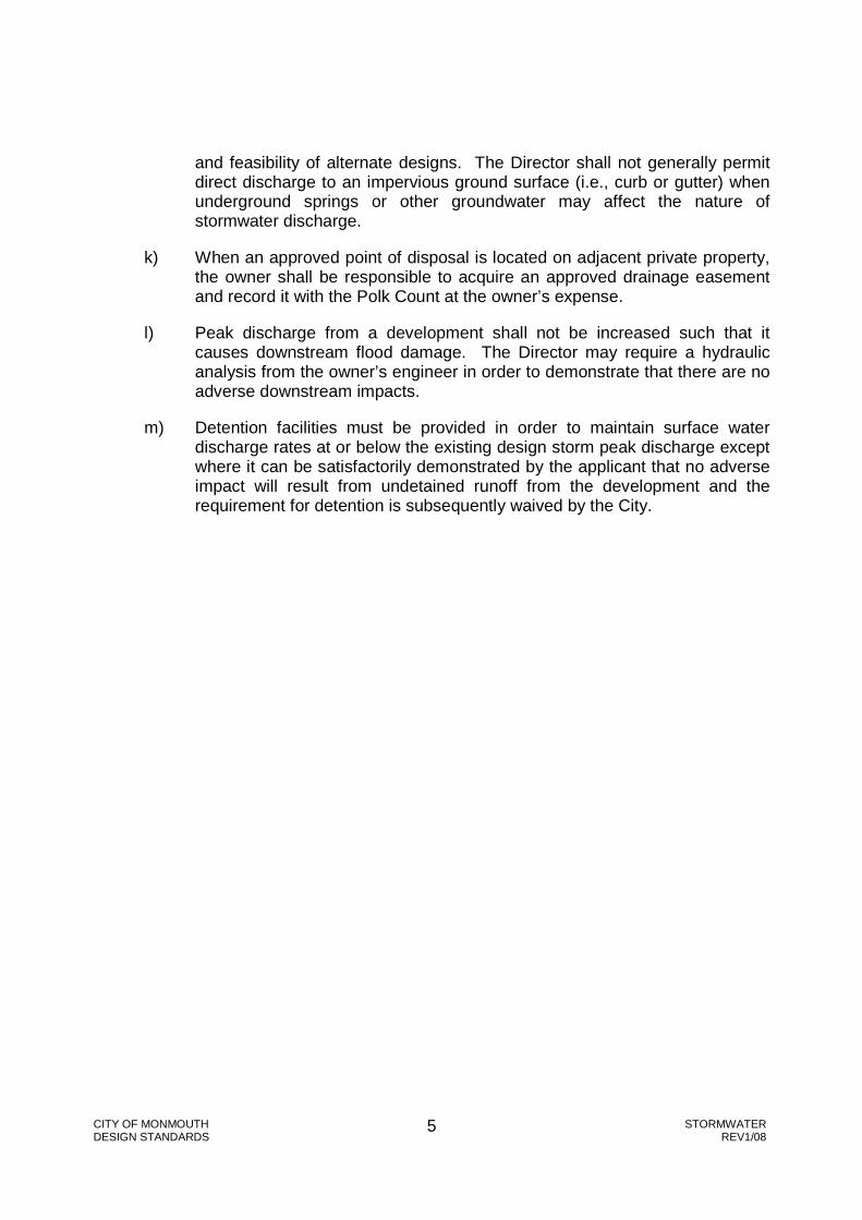
CITY OF MONMOUTH STORMWATER DESIGN STANDARDS REV1/08
5
and feasibility of alternate designs. The Director shall not generally permit direct discharge to an impervious ground surface (i.e., curb or gutter) when underground springs or other groundwater may affect the nature of stormwater discharge.
k) When an approved point of disposal is located on adjacent private property, the owner shall be responsible to acquire an approved drainage easement and record it with the Polk Count at the owner’s expense.
l) Peak discharge from a development shall not be increased such that it causes downstream flood damage. The Director may require a hydraulic analysis from the owner’s engineer in order to demonstrate that there are no adverse downstream impacts.
m) Detention facilities must be provided in order to maintain surface water discharge rates at or below the existing design storm peak discharge except where it can be satisfactorily demonstrated by the applicant that no adverse impact will result from undetained runoff from the development and the requirement for detention is subsequently waived by the City.

CITY OF MONMOUTH STORMWATER DESIGN STANDARDS REV1/08
6
SECTION 2 - STORMWATER QUALITY
2.00 General
Refer to City of Monmouth Stormwater Quality Best Management Practices.
CITY OF MONMOUTH STORMWATER DESIGN STANDARDS REV1/08
7
SECTION 3 - STORMWATER QUANTITY
3.00 Runoff Calculations
a) Drainage Areas
All designs shall identify drainage areas within and upstream of the development. In undeveloped drainage areas, drainage calculations shall separately consider existing drainage patterns and post-developed drainage patterns.
b) Analytical Methods
The engineer is not limited to any one method for calculating runoff. Drainage areas less than 15 acres in size may be analyzed using the rational method. Areas larger than 15 acres must use an analytical method acceptable to the Director. Engineers are encouraged to use FEMA flow quantities for FEMA-studied waterways and Master Plan flow quantities when available for other waterways.
c) Rational Method
The rational method calculation shall be made as follows:
Q = CIA
Q = Peak flow (cubic feet/second) C = Runoff Coefficient I = Rainfall Intensity (inches/hour) A = Drainage Area (acres)
(i) Runoff Coefficient “C”
The runoff coefficient is difficult to estimate because it represents the interaction of many complex factors including surface ponding, infiltration, antecedent moisture, ground cover conditions, ground slopes, and soil type. The actual runoff coefficient for a given drainage basin can best be approximated by calculating a weighted average of all distinct surface types:
CavgCxAx
Atotal= ∑
Table 1 represents typical average values.
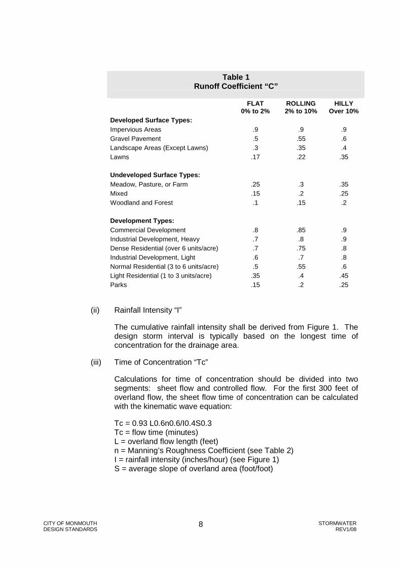
CITY OF MONMOUTH STORMWATER DESIGN STANDARDS REV1/08
8
Table 1 Runoff Coefficient “C”
FLAT
0% to 2% ROLLING 2% to 10%
HILLY Over 10%
Developed Surface Types: Impervious Areas .9 .9 .9 Gravel Pavement .5 .55 .6 Landscape Areas (Except Lawns) .3 .35 .4 Lawns .17 .22 .35 Undeveloped Surface Types: Meadow, Pasture, or Farm .25 .3 .35 Mixed .15 .2 .25 Woodland and Forest .1 .15 .2 Development Types: Commercial Development .8 .85 .9 Industrial Development, Heavy .7 .8 .9 Dense Residential (over 6 units/acre) .7 .75 .8 Industrial Development, Light .6 .7 .8 Normal Residential (3 to 6 units/acre) .5 .55 .6 Light Residential (1 to 3 units/acre) .35 .4 .45 Parks .15 .2 .25
(ii) Rainfall Intensity “I”
The cumulative rainfall intensity shall be derived from Figure 1. The design storm interval is typically based on the longest time of concentration for the drainage area.
(iii) Time of Concentration “Tc”
Calculations for time of concentration should be divided into two segments: sheet flow and controlled flow. For the first 300 feet of overland flow, the sheet flow time of concentration can be calculated with the kinematic wave equation:
Tc = 0.93 L0.6n0.6/I0.4S0.3 Tc = flow time (minutes) L = overland flow length (feet) n = Manning’s Roughness Coefficient (see Table 2) I = rainfall intensity (inches/hour) (see Figure 1) S = average slope of overland area (foot/foot)
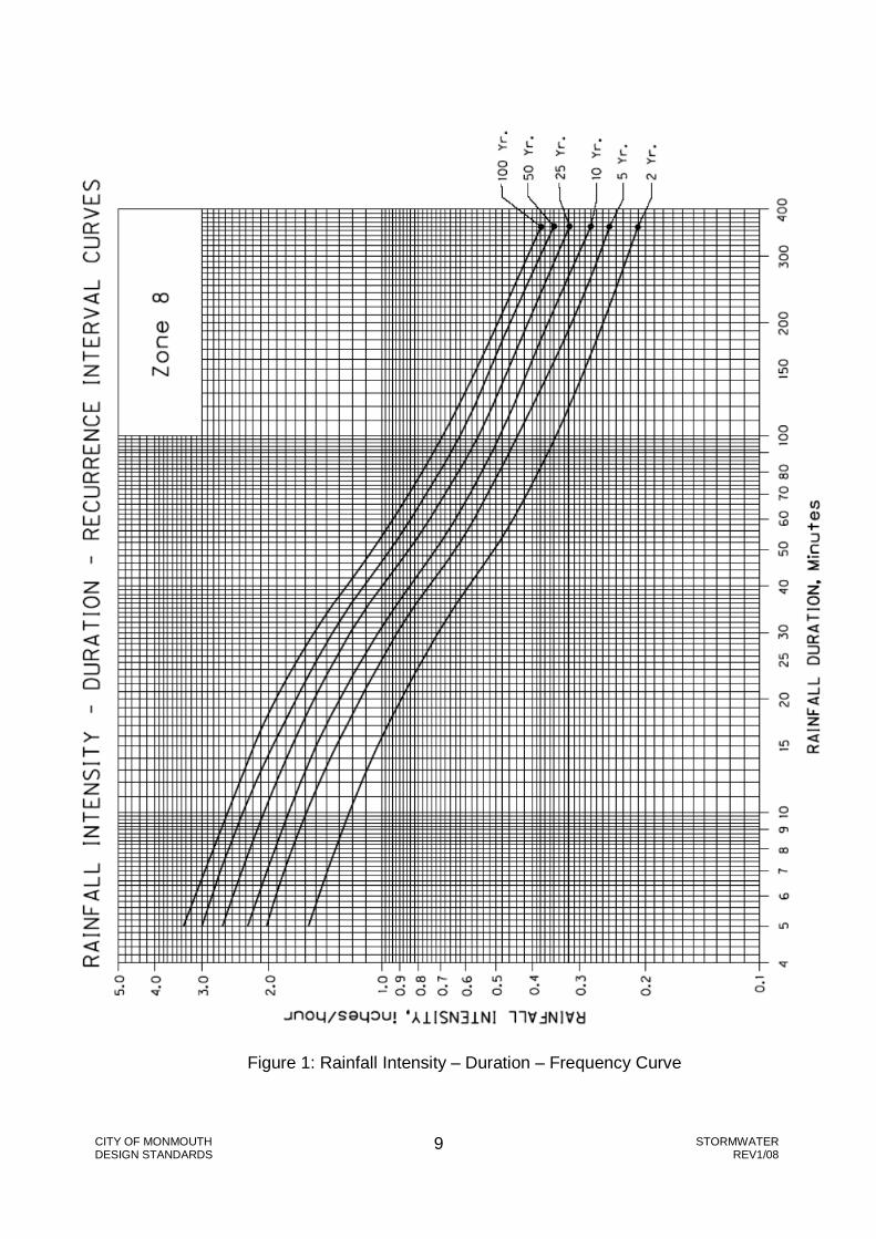
CITY OF MONMOUTH STORMWATER DESIGN STANDARDS REV1/08
9
Figure 1: Rainfall Intensity – Duration – Frequency Curve

CITY OF MONMOUTH STORMWATER DESIGN STANDARDS REV1/08
10
Table 2 Manning’s Roughness Coefficients For Overland Sheet Flow
Surface Types: n
Impervious Areas 0.014 Gravel Pavement 0.02 Developed: Landscape Areas (Except Lawns) 0.08 Undeveloped: Meadow, Pasture, or Farm 0.15 Developed: Lawns 0.24 Undeveloped: Mixed 0.30 Undeveloped: Woodland and Forest 0.40 Development Types: n Commercial Development 0.015 Industrial Development, Heavy 0.04 Industrial Development, Light 0.05 Dense Residential (over 6 units/acre) 0.08 Normal Residential (3 to 6 units/acre) 0.20 Light Residential (1 to 3 units/acre) 0.30 Parks 0.40
For overland flow distances greater than 300 feet, sheet flow typically becomes shallow concentrated flow. The average velocity for this flow can be determined from Figure 2 (source: 1972 Soil Conservation Service Handbook), in which the average velocity is a function of watercourse slope and surface type. For open channels, Manning’s equation should be used to estimate average flow velocity.
Once velocity is calculated, time of concentration can be calculated as follows:
Tc = L/V Tc = flow time (seconds) V = flow velocity (feet/second) L = flow length (feet)
3.01 General Detention Requirements
a) All stormwater runoff originating from and/or draining to any proposed development shall be detained, controlled, and/or conveyed in accordance with these Standards. When existing conditions make stormwater detention impractical for all or a portion of a proposed development, the Director may permit compensatory storage volume to be provided in another location within the drainage basin. Except as described in Sect. 3.01, item b), the total runoff within the drainage basin shall not exceed the allowable release rate.

CITY OF MONMOUTH STORMWATER DESIGN STANDARDS REV1/08
11
Figure 2: Average Velocity of Shallow Concentrated Flow

CITY OF MONMOUTH STORMWATER DESIGN STANDARDS REV1/08
12
b) Detention requirements may be modified as follows at the discretion of the Director:
(i) Developments in critical drainage basins with history of flooding or other drainage problems.
(ii) Redevelopments of existing impervious areas if construction of such detention facilities is not feasible or practical.
(iii) Developments which require an orifice size less than 2 inches in diameter.
(iv) Projects for which detention may increase peak flows of the downstream storm system such as direct outflow to a major waterway.
(v) Drainage basins with adequate regional detention facilities.
(vi) Other special conditions that the Director deems necessary to warrant an increase or reduction in detention capacity or allowable release rate.
(vii) Single family residences or single family residential partitions.
c) Detention facilities shall be open basins or ponds located outside the public right-of-way. Other configurations, such as underground pipes, vaults, or gravel-filled trenches, shall be approved by the Director on a case-by-case basis. Infiltration systems may be subject to the UIC program and registration requirements administered by DEQ.
d) When the on-site drainage system is not designed to detain the off-site runoff, the on-site drainage system (including conveyance, flow restriction, detention, and emergency overflow elements) must be properly designed to address conveyance of off-site runoff through the site.
Stormwater runoff should not flow through the detention system, but instead should flow through the conveyance system. Stormwater runoff should enter the detention system only as redirected by the flow restriction device. When flow through a detention system is approved by the Director, a well-defined low flow channel shall be required.

CITY OF MONMOUTH STORMWATER DESIGN STANDARDS REV1/08
13
e) All aspects of public health, safety, maintenance, nuisance abatement, and vector control must be carefully reviewed in every drainage control system plan. Protective measures are often necessary and shall be required whenever appropriate. The protective measures themselves shall not constitute hazards or nuisances as defined in other applicable codes or standards.
f) The impact of a system failure should be analyzed for effects to the proposed development, adjacent properties, elements of on-site and off-site private storm systems, and elements of the public drainage system.
g) Detention system designs shall minimize frequency, difficulty, and expense of future maintenance. Control structures shall be designed to operate automatically, minimizing operation and maintenance requirements.
h) Multiple-use detention facilities (i.e., parks, playgrounds, tennis courts, basketball courts, parking lots) are encouraged if such a design complies with all other requirements in these Standards.
3.02 Detention Volume Calculations
a) Allowable Outflow
(i) The total outflow from a development shall not exceed the historic, predeveloped five-year design storm runoff from the development area. The Director may further modify the allowable outflow in critical drainage areas. Regardless of the existing predeveloped surface condition, the runoff characteristics for calculating allowable outflow shall typically equal “Undeveloped, Meadow, Pasture, or Farm” as shown in Table 1 and Table 2 and “Fallow or Minimum Tillage Cultivation” as shown in Figure 2.
(ii) Often, small drainage areas within a site are not practical to detain and must flow undetained from the site. Impervious areas of undetained runoff shall be calculated and subtracted from the allowable total outflow through the orifice or other flow-control structure.
b) Outlet Control
Outflow is typically restricted through an orifice, usually located within a manhole or other junction structure. Orifices shall be two inches or greater in size unless otherwise approved by the Director. Orifice sizes shall be established based on the following equation:

CITY OF MONMOUTH STORMWATER DESIGN STANDARDS REV1/08
14
Where:
Q = flow, cfs
d1 = diameter of orifice, inches
d2 = diameter of pipe in which orifice is placed, inches
H = differential head at orifice, feet (measure from upstream water surface to center of orifice)
C = orifice discharge coefficient
The orifice discharge pipe shall be sized to prevent orifice submergence during design conditions.
c) Detention Volume
The detention volume shall be sufficient to detain a 25-year design storm of any duration without overflow. The required detention volume is determined from the storm duration with the greatest difference between total cumulative runoff and allowable cumulative outflow.
3.03 Parking Lot Ponds
a) Maximum depth of water surface on all parking lot ponds shall be one foot.
b) Slopes on all parking lot surface ponds shall not be less than 1 percent nor exceed 5 percent in areas designed for vehicular traffic.
c) A sand and oil separator may be required as specified in Section 2. Stormwater Quality.
d) The maximum water surface elevation of the parking lot pond shall be at least one foot below either of the following, whichever is lower:
(i) the lowest habitable floor elevation; or
(ii) the lowest elevation of mechanical, electrical, or other equipment subject to damage by flooding.
e) The one-foot minimum clearance may be reduced if the detention overflow provides adequate protection from flood damage to the satisfaction of the Director.
4
2
1
1
1
104375.0
−
=
dd
HCdq

CITY OF MONMOUTH STORMWATER DESIGN STANDARDS REV1/08
15
f) Parking lot ponding shall not be provided in underground parking structures.
g) Where curbing is used for detention, the maximum water surface shall be no higher than 0.25 feet below the top of curb, and type “C” curbing shall be used as shown in the Standard Plans.
h) No parking lot ponds shall be located within the primary ingress/egress portions of a site. A minimum 11-foot-wide emergency vehicle lane shall remain outside the detention area or direct overflow path.
3.04 Surface Ponds Other than Parking Lot Ponds
a) Slopes and embankments of surface ponds shall meet the following minimum requirements unless, as approved by the Director, the surface pond design, construction inspection, and construction certification are performed by a geotechnical engineer:
(i) Interior slopes shall be no steeper than 3:1 (3 horizontal to 1 vertical) and exterior slopes shall be no steeper than 2:1. Retaining walls shall not be used within surface ponds.
(ii) The maximum water surface elevation shall not exceed the natural ground surface elevation within the banks of a surface pond. Fill shall not be used as the bank of a surface pond, except for providing freeboard above the maximum water surface elevation.
(iii) Water surface depth shall not exceed three feet.
(iv) The top of berm for any surface pond embankment shall be minimum six feet wide.
b) All surface ponds, including interior and exterior slopes, shall provide accessibility for maintenance and landscaping equipment as determined by the Director. Within the public storm system, ponds over 5,000 square feet in total size shall meet the following requirements:
(i) The bottom of the pond shall have ten feet as a minimum dimension.
(ii) Vehicular access shall be provided from the public right-of-way to the bottom of the pond through a 15-foot-wide access easement with slopes no greater than 5:1 (5-foot horizontal to 1-foot vertical).
NOTE: For the purpose of calculating pond area for this requirement, pond area shall be that area contained within the top of the embankment.
c) Pond design shall give consideration to environmental concerns, landscaping appearance, and erosion control. All ponds shall be
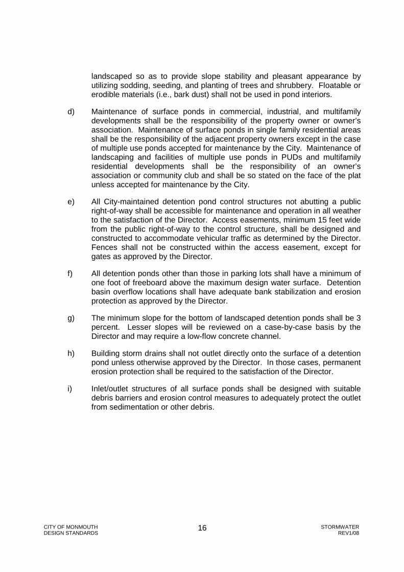
CITY OF MONMOUTH STORMWATER DESIGN STANDARDS REV1/08
16
landscaped so as to provide slope stability and pleasant appearance by utilizing sodding, seeding, and planting of trees and shrubbery. Floatable or erodible materials (i.e., bark dust) shall not be used in pond interiors.
d) Maintenance of surface ponds in commercial, industrial, and multifamily developments shall be the responsibility of the property owner or owner’s association. Maintenance of surface ponds in single family residential areas shall be the responsibility of the adjacent property owners except in the case of multiple use ponds accepted for maintenance by the City. Maintenance of landscaping and facilities of multiple use ponds in PUDs and multifamily residential developments shall be the responsibility of an owner’s association or community club and shall be so stated on the face of the plat unless accepted for maintenance by the City.
e) All City-maintained detention pond control structures not abutting a public right-of-way shall be accessible for maintenance and operation in all weather to the satisfaction of the Director. Access easements, minimum 15 feet wide from the public right-of-way to the control structure, shall be designed and constructed to accommodate vehicular traffic as determined by the Director. Fences shall not be constructed within the access easement, except for gates as approved by the Director.
f) All detention ponds other than those in parking lots shall have a minimum of one foot of freeboard above the maximum design water surface. Detention basin overflow locations shall have adequate bank stabilization and erosion protection as approved by the Director.
g) The minimum slope for the bottom of landscaped detention ponds shall be 3 percent. Lesser slopes will be reviewed on a case-by-case basis by the Director and may require a low-flow concrete channel.
h) Building storm drains shall not outlet directly onto the surface of a detention pond unless otherwise approved by the Director. In those cases, permanent erosion protection shall be required to the satisfaction of the Director.
i) Inlet/outlet structures of all surface ponds shall be designed with suitable debris barriers and erosion control measures to adequately protect the outlet from sedimentation or other debris.
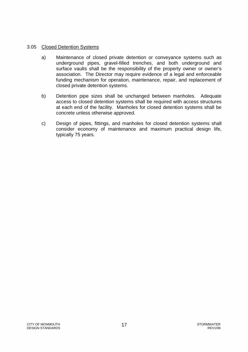
CITY OF MONMOUTH STORMWATER DESIGN STANDARDS REV1/08
17
3.05 Closed Detention Systems
a) Maintenance of closed private detention or conveyance systems such as underground pipes, gravel-filled trenches, and both underground and surface vaults shall be the responsibility of the property owner or owner’s association. The Director may require evidence of a legal and enforceable funding mechanism for operation, maintenance, repair, and replacement of closed private detention systems.
b) Detention pipe sizes shall be unchanged between manholes. Adequate access to closed detention systems shall be required with access structures at each end of the facility. Manholes for closed detention systems shall be concrete unless otherwise approved.
c) Design of pipes, fittings, and manholes for closed detention systems shall consider economy of maintenance and maximum practical design life, typically 75 years.

CITY OF MONMOUTH STORMWATER DESIGN STANDARDS REV1/08
18
SECTION 4 - OUTFALL DESIGN
4.00 General Requirements
The point of disposal for all stormwater within a development may be a storm drain pipe, open channel, curb and gutter, or other approved facility. The Director shall approve all points of disposal. Infiltration systems may be subject to the UIC program and registration requirements administered by DEQ.
As a condition of development, the Director may require a downstream analysis of the existing public or private drainage system. The minimum level of analysis shall generally extend downstream from the project to a point in the drainage system where the proposed development constitutes less than 15 percent of the total drainage area. The level of analysis required by the Director will vary depending upon site conditions, preexisting problems within the basin, and the size of development.
4.01 Outfalls to Open Channel Waterways
a) Direct outfalls greater than four inches in diameter to open channel waterways shall typically be designed by a licensed engineer. Outfalls shall be constructed to minimize the potential for erosion and other potential damage to the waterway banks. Outfall designs shall address erosion and scouring within the waterway upstream and downstream of the outfall structure.
b) Bank stabilization shall not reduce the carrying capacity of the water course. Bank stabilization designs shall consider the 10-year flow velocities of pipe outlets and 25-year flow velocities of open channel waterways (see Figure 3 for stone sizing guidelines). Where stones are placed within existing bank slopes, the bank shall typically be excavated a minimum of 18 inches or 1.5 times the size of the largest stone being used, whichever is greater.
c) Flow from the outfall structure shall be directed downstream, typically no less than 30 degrees from perpendicular to the waterway flow.
d) The outfall invert shall typically be located at the normal low water level of the waterway. At times when the waterway surface is higher than the normal low water level, the outfall invert shall be located as near the water surface as practicable to the satisfaction of the Director. The Director may require the developer to construct additional bank stabilization below the outfall invert at a later time when the waterway surface elevation has decreased. In such cases of delayed bank stabilization, the Director may require an acceptable performance security prior to approval.

CITY OF MONMOUTH STORMWATER DESIGN STANDARDS REV1/08
19
Figure 3: Size of Stone that will resist displacement for Various Velocities and Side Slopes

CITY OF MONMOUTH 20 STORMWATER DESIGN STANDARDS REV1/08
SECTION 5 - CONVEYANCE SYSTEM DESIGN
5.00 General Conditions
a) Conveyance systems, whether pipes or open channels, are classified according to the size of the drainage area contributing directly to the conveyance system.
Table 3 - Waterway Classifications
Waterway Classification
Drainage Area
Waterway Example
A 150 Square Miles or Greater Willamette River
B 10 to150 Square Miles Ash Creek
C 1 to 10 Square Miles South Fork Ash Creek above Talmage Road
D 200 Acres to 1 Square
Mile Tributary to Middle Fork Ash Creek at Gentle Woods Park
E 50 to 200 Acres 48-inch Dalke Storm Sewer outlet at Madrona Park
F Up to 50 Acres Local storm drainage systems
When a drainage area discharges into multiple waterways, the Director will determine the Waterway Classification based on flow characteristics or other related information.
b) Conveyance Systems shall generally be underground pipes. Exceptions may be approved by the Director on a case-by-case basis.

CITY OF MONMOUTH 21 STORMWATER DESIGN STANDARDS REV1/08
c) Conveyance systems shall be designed and constructed in compliance with requirements of all applicable Federal, State, and local agencies. Written authorization of approval from other jurisdictions may be required at the Director’s discretion.
d) Conveyance systems shall be designed and constructed such that the cumulative incremental effects of such work considered alone or together with existing or similar projects in the vicinity will not result in substantial damage to existing waterways and surface waters by erosion, siltation or sedimentation, significant adverse effects to water quality, increased downstream water velocity, significant harmful deterioration of groundwater drainage, or significant deterioration of aquatic wildlife habitat as determined by the Director.
e) Conveyance systems shall be designed and constructed in accordance with floodplain management policies and regulations in accordance with MDC Chapter 51 and other National Flood Insurance Program requirements as determined by the Director.
5.01 Capacity
a) Conveyance systems shall be constructed to carry the designated design storm, flowing full as shown in Table 4:
Table 4: Design Storm
Waterway Classification Design Storm
A, B, C 100-Year
D, E 25-Year
F 10-Year
Special flood hazard areas within Waterway Classifications D, E, or F may require 100-year capacity as determined by the Director.
b) Manning’s Formula shall generally be acceptable for determining pipe or open channel capacity only within Waterway Classifications E and F. Backwater effects shall be included in determining capacity for Waterway Classifications A, B, C, and D, typically using HEC-RAS or equivalent computer modeling software.

CITY OF MONMOUTH 22 STORMWATER DESIGN STANDARDS REV1/08
5.02 Piped Systems
a) Size
Main line and lateral storm drains shall be not less than 10 inches inside diameter, except as approved by Director. If a storm drain pipe is accessible only through a catch basin or otherwise has limited access, the Director may require a minimum 12-inch inside diameter.
b) Slope Requirements
All storm drains shall be laid on a grade which will produce a mean velocity (when flowing full) of at least 2½ feet per second, based upon Manning’s pipe friction formula using a roughness coefficient as described in Section 5.02(c) Manning’s Roughness Coefficient. The minimum acceptable grade for various pipe sizes with a Manning’s Roughness Coefficient of 0.013 is shown in Table 5.
Table 5 Minimum Pipe Grade for Storm Sewers
with n = 0.013
Inside Pipe Diameter (inches)
Grade (feet per 100 feet)
8 (private) 0.52
10 0.39
12 0.30
15 0.23
18 0.18
21 0.14
24 0.12
27 0.10
30 (and larger) 0.09

CITY OF MONMOUTH 23 STORMWATER DESIGN STANDARDS REV1/08
The minimum grade may be reduced from the above table to produce an absolute minimum velocity of 2.0 fps upon approval of the Director. The maximum grade is 20 percent except as approved by the Director.
Engineers are cautioned not to specify storm drains of sizes which are obviously larger than is necessary for satisfactory carrying capacity but which are specified in order to meet grade requirements, i.e., a 12-inch pipe for a 10-inch pipe to acquire a decrease in slope.
c) Manning’s Roughness Coefficient
Manning’s Roughness Coefficient (“n”) is typically provided by the pipe manufacturer for new construction. The “n” value for existing pipes varies based on material, condition, interior wall configuration, and other related factors as shown in Table 6.
Table 6: Manning’s Roughness Coefficients for Exis ting Pipes
Pipe Material “n” Value Range
Plastic (PVC, HDPE) 0.009-0.013
Concrete 0.013-0.015
Ductile Iron 0.013-0.015
Cast Iron 0.013-0.015
Corrugated Metal 0.013-0.032
d) Pipe Materials
Pipe materials for public storm drains shall conform to Standard Construction Specifications. Acceptable pipe materials and abbreviations are as follows:
PVC—Polyvinyl Chloride
HDPE—High Density Polyethylene
CMP—Corrugated Metal Pipe
CONC—Concrete
DI—Ductile Iron

CITY OF MONMOUTH 24 STORMWATER DESIGN STANDARDS REV1/08
The Director may require pipe load analysis calculations in unusual situations, typically in areas where the depth of ground cover over the pipe is not within the limits specified by the pipe manufacturer.
Alternate materials will be approved on a case-by-case basis. The design engineer shall provide manufacturer’s specifications, design calculations, or other information as required by the Director.
e) Alignment/Location
(i) Typically, storm drains shall be located in the street right-of-way within two feet of the curbline and preferably on the low side of the street, except when catch basin location warrants otherwise.
(ii) Storm drains shall generally be laid on a straight alignment between junctions. Pipes may be laid with horizontal or vertical curvature according to manufacturer’s specifications as approved by the Director.
(iii) Utility crossings shall be constructed as near 90 degrees as practicable. Utility crossings with less than six inches of vertical separation shall be backfilled with controlled density backfill or other approved material. Utility crossings with six inches or greater vertical separation may require granular or other special backfill as specified by the Director.
(iv) Where storm drains parallel other utility pipe or conduit lines, the vertical and horizontal alignment shall permit future side connections of main or lateral storm drains and avoid conflicts with parallel utilities without abrupt changes in vertical grade of main or lateral storm drains.
(v) Storm drain alignments shall accommodate future planned projects such as street widening, changes in horizontal or vertical street alignment, and master plan water or sewer facilities.
f) Cover Requirements
(i) All storm drains shall be laid at a depth sufficient to protect against damage by traffic and to drain building footings and underfloors where practical. Depth is measured from top of pipe to finish grade at the storm drain alignment.
(ii) Under normal conditions, minimum cover shall be 30 inches above the top of the pipe. Pipes designed with less than 30 inches of cover shall be approved by the Director on a case-by-case basis and may require special bedding and/or backfill, load calculations,
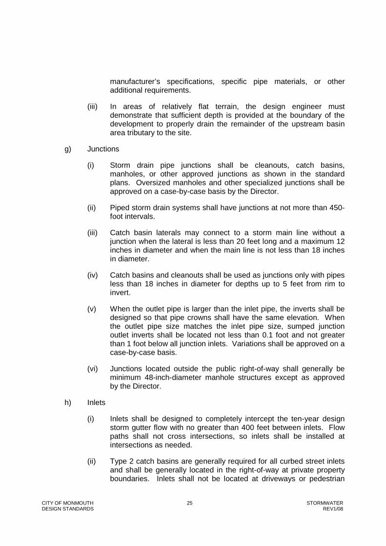
CITY OF MONMOUTH 25 STORMWATER DESIGN STANDARDS REV1/08
manufacturer’s specifications, specific pipe materials, or other additional requirements.
(iii) In areas of relatively flat terrain, the design engineer must demonstrate that sufficient depth is provided at the boundary of the development to properly drain the remainder of the upstream basin area tributary to the site.
g) Junctions
(i) Storm drain pipe junctions shall be cleanouts, catch basins, manholes, or other approved junctions as shown in the standard plans. Oversized manholes and other specialized junctions shall be approved on a case-by-case basis by the Director.
(ii) Piped storm drain systems shall have junctions at not more than 450-foot intervals.
(iii) Catch basin laterals may connect to a storm main line without a junction when the lateral is less than 20 feet long and a maximum 12 inches in diameter and when the main line is not less than 18 inches in diameter.
(iv) Catch basins and cleanouts shall be used as junctions only with pipes less than 18 inches in diameter for depths up to 5 feet from rim to invert.
(v) When the outlet pipe is larger than the inlet pipe, the inverts shall be designed so that pipe crowns shall have the same elevation. When the outlet pipe size matches the inlet pipe size, sumped junction outlet inverts shall be located not less than 0.1 foot and not greater than 1 foot below all junction inlets. Variations shall be approved on a case-by-case basis.
(vi) Junctions located outside the public right-of-way shall generally be minimum 48-inch-diameter manhole structures except as approved by the Director.
h) Inlets
(i) Inlets shall be designed to completely intercept the ten-year design storm gutter flow with no greater than 400 feet between inlets. Flow paths shall not cross intersections, so inlets shall be installed at intersections as needed.
(ii) Type 2 catch basins are generally required for all curbed street inlets and shall be generally located in the right-of-way at private property boundaries. Inlets shall not be located at driveways or pedestrian

CITY OF MONMOUTH 26 STORMWATER DESIGN STANDARDS REV1/08
ramps; Type 1 catch basins may be used when a curb inlet is impracticable as determined by the Director.
(iii) Inlets shall be located along the gutter line or open channel flow-line. When streets are widened or otherwise modified, causing an inlet to be located outside a flow-line, the inlet shall be removed entirely and reconstructed with a cleanout, manhole, or other acceptable junction as specified by the Director.
i) Subsurface Drainage
Subsurface drains shall be constructed with adequate erosion protection and shall discharge into the public storm drain system only as provided by the Director. Subsurface drains may be required by the Director as follows:
(i) Excavations and fills, with or without retaining walls, which exceed 4 feet vertically.
(ii) Any development within areas of existing springs or high groundwater levels.
j) Easements
(i) Piped storm systems shall generally be located in the right-of-way. When design conditions require locating storm drains in easements, the storm drain shall typically be centered in the easement. An easement may be centered on a property line only if the pipe centerline is located within 18 inches of the property line.
(ii) Storm drain easements shall be minimum 15 feet wide for pipes up to 36 inches in diameter. Easements for pipes over 36 inches in diameter shall be 20 feet wide or greater as determined by the Director.
(iii) Storm drain easements shall typically be exclusive. Combined easements shall be approved by the Director on a case-by-case basis.
(iv) All junction or inlet structures in easements shall be accessible to City of Monmouth maintenance personnel at all times. A minimum 15-foot-wide access easement is required between the nearest right-of-way and each structure. Paved or gravel access roads shall be required by the Director if access is otherwise unavailable.
(v) All easements shall be furnished to the City for review and approval prior to recording.

CITY OF MONMOUTH 27 STORMWATER DESIGN STANDARDS REV1/08
5.03 Open Channel Drainage
a) General Considerations
(i) Open channels shall generally have a natural curvilinear alignment with a 100-foot-minimum flow-line radius and a low-flow channel designed to convey the appropriate design storm (See Table 4).
(ii) Banks shall be designed with a minimum one foot of freeboard above the design storm. The surface configuration at the top of bank should provide adequate accessibility for maintenance as determined by the Director.
b) Slope Requirements
(i) Bank slopes shall generally be no steeper than 3:1 (3 horizontal to 1 vertical). In areas where 3:1 side slopes are impracticable because of existing natural features or other limitations obstructing the channel, the bank slope shall generally be no steeper than 2:1. If the top of bank is a berm, the backslope shall generally be no steeper than 2:1 and shall be graded to prevent localized ponding. In areas of potential instability, the Director may, at his discretion, require grading to be designed by a geotechnical engineer.
(ii) The flow-line slope is generally dictated by the natural contours. The minimum flow-line slope is 3 percent where practicable, but in no case shall the design flow velocity be less than two feet per second except as approved by the Director.

CITY OF MONMOUTH 28 STORMWATER DESIGN STANDARDS REV1/08
c) Manning’s Roughness Coefficient
Manning’s Roughness Coefficient (“n”) shall generally comply with the ODOT Hydraulic Manual. Typical “n” value ranges are shown in Table 7.
Table 7: Manning’s Roughness Coefficients for Open Channels
Description “n” Value Range
Concrete-lined open channel 0.012-0.020
Rock-lined open channel 0.015-0.045
Vegetated swale with short grass 0.022-0.035
Vegetated channel with periodic maintenance
0.030-0.120
Natural waterway (surface width <100 feet)
0.030-0.220
Major waterway (surface width >100 feet) 0.020-0.040
d) Bank Stabilization
Open channel waterways shall be designed and constructed with temporary and permanent bank stabilization measures in all locations. Specialized bank stabilization shall be considered as follows:
(i) In Waterway Classifications A, B, C, and D, natural bank stabilization measures (i.e., slope pull-back, willow mats, rock barbs, or revegetation with localized native plant species) shall be used where practicable unless otherwise approved by the Director.
(ii) Areas of extreme curvature, changes in channel cross-section, or low-flow channels with design flow velocities exceeding three feet per second shall be designed and constructed with bank stabilization to consider additional potential for scouring from turbulent flows.
(iii) Post-construction bank stabilization shall minimize the potential for erosion or sedimentation.
(iv) In areas of waterway convergence or other points of disposal, bank stabilization shall meet the requirements of Section 4 – Outfall Design.

CITY OF MONMOUTH 29 STORMWATER DESIGN STANDARDS REV1/08
e) Easements
(i) Open channel easement widths shall be the 100-year floodway, 15 feet from the channel centerline, or 10 feet from the top of the recognized bank, whichever is greater.
(ii) All easements shall be furnished to the City for review and approval prior to recording.

CITY OF MONMOUTH DEPARTMENT OF PUBLIC WORKS
DESIGN STANDARDS
CHAPTER 5
WATER DISTRIBUTION
CITY OF MONMOUTH DEPARTMENT OF PUBLIC WORKS
401 HOGAN ROAD N. MONMOUTH, OREGON 97361
TELEPHONE: (503) 838-2173
FAX: (509) 838-0201
REVISED JANUARY 2008
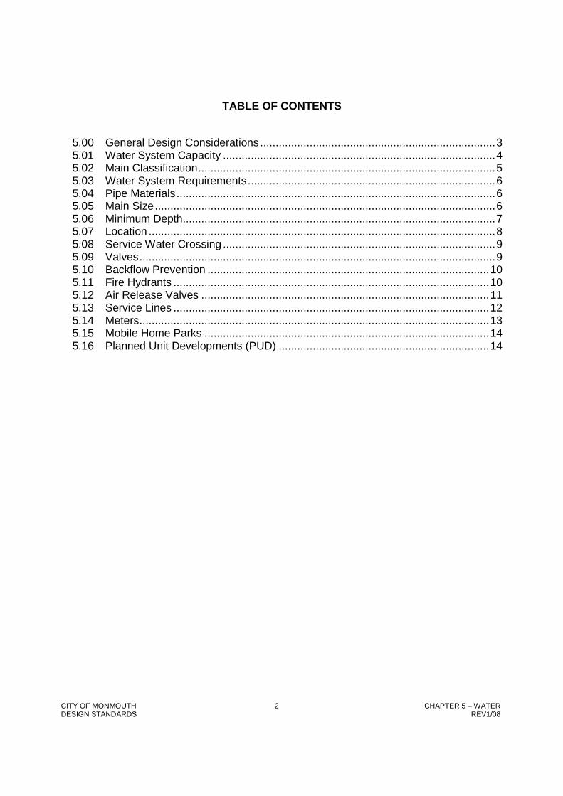
CITY OF MONMOUTH 2 CHAPTER 5 – WATER DESIGN STANDARDS REV1/08
TABLE OF CONTENTS
5.00 General Design Considerations ............................................................................3 5.01 Water System Capacity ........................................................................................4 5.02 Main Classification................................................................................................5 5.03 Water System Requirements................................................................................6 5.04 Pipe Materials.......................................................................................................6 5.05 Main Size..............................................................................................................6 5.06 Minimum Depth.....................................................................................................7 5.07 Location ................................................................................................................8 5.08 Service Water Crossing ........................................................................................9 5.09 Valves...................................................................................................................9 5.10 Backflow Prevention ...........................................................................................10 5.11 Fire Hydrants ......................................................................................................10 5.12 Air Release Valves .............................................................................................11 5.13 Service Lines ......................................................................................................12 5.14 Meters.................................................................................................................13 5.15 Mobile Home Parks ............................................................................................14 5.16 Planned Unit Developments (PUD) ....................................................................14

CITY OF MONMOUTH 3 CHAPTER 5 – WATER DESIGN STANDARDS REV1/08
5.00 General Design Considerations
The system shall have sufficient capacity to maintain 40 psi at the building entrance for one- and two-family dwellings. For other development provide minimum pressure of 35 PSI at the building side of the meter during periods of maximum use, and to provide sufficient volumes of water at adequate pressures to satisfy the expected daily consumption plus fire flows. Normal working pressure in the distribution system should be approximately 60 PSI with a range of 40 PSI to 100 PSI.
In general, water distribution systems should be designed to care for maximum development of the service area with recognition of possible urban renewal, industrial expansion, etc.
As a condition of water service, all developments will be required to provide public water mains of sufficient size for fire protection to adjacent parcels. This shall include the extension of water mains in easements across the property to adjoining properties and across the street frontage of the property to adjoining properties when the main is located in the street right-of-way.
Head loss shall be determined by the Hazen-Williams equation.
Value Table
Pipe Diameter C Value
8 Inches and Less 100
10 to 12 Inches 110
Greater than 12 Inches 120
Velocities in mains shall normally range from three to six feet per second for average demand to a maximum velocity of ten (10)* feet per second for combined average demand plus fire flow. A 20-PSI residual pressure under fire flow conditions shall be maintained in the distribution system where the existing static pressure is less than 40 PSI (upper service level regions). Generally, a maximum velocity of ten (10) feet per second will govern for sizing mains at all other locations of the service level.
*Private systems shall limit velocities as required by the Oregon State Plumbing Specialty Code, Installation.

CITY OF MONMOUTH 4 CHAPTER 5 – WATER DESIGN STANDARDS REV1/08
5.01 Water System Capacity
Design capacities shall be determined by consideration of the following factors and assumptions:
a) Area to be served, both immediate and adjacent;
b) Current and projected population within the areas to be served;
c) Current and projected land use within the areas to be served;
d) Commercial, industrial, or institutional users to be served;
e) Changes in any of the above factors which are likely to occur within a foreseeable time period.
In the absence of consumption data or other reliable information, the following factors are assumptions:
a) Peak hour demands are as follows: 0.75 gpm per person for single family residential
0.25 gpm per person for multiple family residential
5,000 gal/ac/day for commercial development
10,000 gal/ac/day for industrial development
b) Demand for unique commercial installations, industrial users, PUD's, multiple, and institutional concerns will be calculated on an individual basis.
c) Fire flows shall be as prescribed by Polk County Fire District #1 and the Oregon Fire Code (OFC):
d) Commercial Buildings: The minimum available fire flow and duration shall be determined according to OFC Appendix B (OFC B 105.1).

CITY OF MONMOUTH 5 CHAPTER 5 – WATER DESIGN STANDARDS REV1/08
Land Use Fire Flows (GPM)
Duration (Hr.)
Industrial 5,500 4
Downtown 5,000 4
Commercial 4,000 3
Multiple Family 3,500 2
Residential 1,000 2
All Others 1,000 2
5.02 Main Classification
f) Supply Mains (Transmission Mains) Mains which are used for transporting water from the source of supply and storage reservoirs to the centralized point of distribution and distribution reservoirs.
g) Feeder Mains Mains which transport water from centralized points of distribution and distribution reservoirs, to the various points of interconnection with the grid system of mains and centralized points of consumption. There are two types of feeder mains:
(i) Primary - Those feeder mains not supplying individual consumers, but their sole purpose being to transport water from centralized points of distribution to various points of interconnection with the grid system and centralized points of consumption.
(ii) Secondary - Those feeder mains which serve the same purpose as any other feeder mains except that individual consumers are served by this group, due either to the fact that no other main is available or that the required supply to the consumer demands a large main.
h) Distribution Mains All mains which are used for supplying the individual consumer. As a general rule these are the small mains in the water supply system.

CITY OF MONMOUTH 6 CHAPTER 5 – WATER DESIGN STANDARDS REV1/08
5.03 Water System Requirements
The physical design requirements for public water main systems in the City are contained in this chapter. These design requirements may be used for private systems, provided the system is designed by a registered professional civil engineer.
5.04 Pipe Materials
All water mains and services shall be designed for a cold water test pressure of 150 PSI (refer to AWWA C 150 (76) and CIPRA Technical Bulletin “Designing for Ductile Iron Pipe.”) Fittings and valves shall be specified to have a test pressure of 250 PSI.
PVC pressure pipe with diameters of 4 in thru 12 in shall conform to AWWA C900. The pipe shall have electrometric gasket joints conforming with ASTM D 3139. Gaskets will conform with ASTM F 477 and ASTM D 1869.
PVC pressure rated pipe shall conform to ASTM 2241. The joints shall be electrometric gasket or solvent cement welded. Gasket joints shall conform with ASTM F 447 and ASTM D 1869. Solvent cement welded joints shall conform with ASTM D 2672 or ASTM D 3036. Solvent shall conform to ASTM D 2564.
Six-inch (6) through thirty-inch (30) - DUCTILE IRON PIPE shall conform to ANSI A21.51 (AWWA C151), thickness Class 50 Ductile Iron Pipe (four-inch shall be Class 51) and shall be standard thickness cement lined conforming to ANSI A21.10 (AWWA C110). Joints shall be rubber gasket of either the push-on or mechanical joint type conforming to ANSI A21.11 (AWWA C111). Higher thickness class may be required where analysis indicates abnormal loading condition (see AWWA H-3).
Fourteen-inch (14) and Larger - Special Conditions - Acceptable alternate materials for large supply mains when soil conditions are suitable and when a minimum of service connections are to be connected to the main include Ductile Iron, reinforced concrete water pipe, steel cylinder type, pretensioned conforming to AWWA C303.
5.05 Main Size
a) Grid System The distribution system mains shall be looped at all possible locations. The installation of permanent dead-end mains upon which fire protection depends and areas of large demands on single mains will not be permitted.

CITY OF MONMOUTH 7 CHAPTER 5 – WATER DESIGN STANDARDS REV1/08
b) Size of Pipe
2 inch Shall not be used as part of the distribution system, but for services only.
3 inch Shall not be used as part of the distribution system but for services only downstream of the meter.
4 inch Shall not be used as part of the distribution system but for services only downstream of the meter.
6 inch Minimum size residential subdivision distribution water main for the grid (looped) system, not to exceed an unsupported length of 600 feet and shall not be permanently dead-ended. Looping of the distribution grid shall be at least every 600+ feet.
8 inch Minimum size for permanently dead-ended mains supplying fire hydrants with a fire flow less than 2,000 gpm and for secondary feeder mains in residential subdivisions.
12 inch And larger as required for primary feeder mains and mains in industrial subdivisions.
All dead-end mains shall terminate with a blow-off assembly. Permanent dead-ends shall have a blow-off assembly as per the Standard Plans. Mains which can conceivably be extended at some later date shall have a blow-off assembly as per the Standard Plans. Where curbs exist, the blow-off shall be located in front of the curb at least five (5) feet from the curb face.
5.06 Minimum Depth
The standard minimum cover over buried water mains within the street right-of-way except the paved area shall be thirty-six (36) inches from finish grade referenced from the existing top of curb or proposed top of curb elevation. The paved area of the street right-of-way shall have a minimum cover of thirty (30) inches.
The minimum cover for mains in easements across private property shall be thirty-six (36) inches.
Finish grade shall normally mean the existing or proposed top of curb elevation. Where the main is located in the cut or fill side slope or where mains are located in easements, finish grade shall mean at the water main alignment. The intent is to
CITY OF MONMOUTH 8 CHAPTER 5 – WATER DESIGN STANDARDS REV1/08
provide a minimum cover over the pipe of 30 inches in the street right-of-way and 36 inches in easements.
5.07 Location
a) Relation to Sewer Lines and Other Utilities Water lines shall be separated from other utilities in accordance with OAR 333.
b) Water Mains Within Street Right-of-Way The standard location for water mains within public streets and roads shall be at the backside of the sidewalk and preferably on the south and west sides of the street. Exceptions to these requirements may be made in order to avoid conflicts with other existing underground facilities, and to permit sanitary sewers to be installed on the low sides of streets.
Mains shall not be installed in alleys. As nearly as practical, mains shall be installed on a particular street with the distance from the curb line of the street varied as little as possible. On curved streets, mains may be laid on a curve concentric with the street centerline with deflections no greater than the manufacturer's specifications, or mains may be laid in straight lines along the tangent between selected angle points to avoid conflicts with other utilities. The angle point and tangent section shall not be less than three (3) feet in front of the curb face.
c) Within Easements Mains laid in easements along property line, with the easements centered on property line, shall be offset 18 inches from the property line. The installation of mains within easements across privately owned property is to be done only when absolutely necessary, such as the avoidance of dead-end conditions. Such easements, when required, shall be exclusive and a minimum of ten (10) feet in width except that the minimum width shall be twenty (20) feet or more for transmission water mains and the conditions of the easement shall be such that the easement shall not be used for any purpose which would interfere with the unrestricted use for water main purposes. Under no circumstances shall a building or structure be placed over a water main or water main easement. This includes overhanging structures with footings located outside the easement. The intent is to provide an unobstructed area above the easement in which to operate or repair equipment.
Easement locations for public mains serving a PUD, apartment complex, or commercial/industrial development shall be in parking lots, private drives, or similar open areas which will permit an unobstructed vehicle access for maintenance by City forces.

CITY OF MONMOUTH 9 CHAPTER 5 – WATER DESIGN STANDARDS REV1/08
Easement widths shall vary from the ten (10) foot minimum by five (5) foot increments, i.e., 10, 15, 20 feet, etc. Easements must be from the property owner to the City of Monmouth prior to construction.
Common placement in the easement of water, sewer, and storm drain line may be allowed under certain conditions.
Common easements will be reviewed on a case-by-case basis. Separation of utilities must meet State of Oregon Department of Environmental Quality and Health Division requirements.
All easements must be furnished to the City for review and approval prior to recording.
5.08 Service Water Crossing
Surface water crossings of mains shall be in accordance with OAR 333 and the following.
a) Mains crossing stream or drainage channels shall be designed to cross as nearly perpendicular to the channel as possible.
b) The following water surface crossings will be treated on a case-by-case basis:
(i) Stream or drainage channel crossing for pipes of twelve (12) inch inside diameter and greater.
(ii) River or creek crossings requiring special approval from the Division of State Lands.
c) The minimum cover from the bottom of the stream bed or drainage channel to the top of pipe shall be thirty-six (36) inches.
d) A scour pad centered on the water line will be required for mains less than twelve (12) inch inside diameter when the cover from the top of the pipe to the bottom of the stream bed or drainage channel is thirty (30) inches or less. The scour pad shall be six (6) inches thick and six (6) feet wide reinforced with number four bars twelve (12) inches on center both ways and shall extend to a point where a one-to-one slope, that begins at the top of the bank and slopes down from the bank away from channel center line intersects the top of the pipe.
5.09 Valves
a) Sizes In general, valves shall be the same size as the mains in which they are installed.

CITY OF MONMOUTH 10 CHAPTER 5 – WATER DESIGN STANDARDS REV1/08
b) Location Distribution system valves shall be located at the tee or cross fitting as nearly as possible. Wherever a conflict exists with curbs, etc., the valve shall be located at the intersection of the main with a property line. There shall be a sufficient number of valves so located that not more than four (4) and preferably three (3) valves must be operated to affect any one particular shutdown. The spacing of valves shall be such that the length of any one shutdown in high value areas shall not exceed 500 feet or 800 feet in other areas.
In general, a tee-intersection shall be valved in two branches and a cross-intersection shall be valved in three branches. Transmission water mains shall have valves at not more than 2,000 foot spacings and preferably 1,300 foot spacings. Hazardous crossings, such as creek, railroad, and freeway crossings, shall be valved on each side.
Distribution taps on transmission mains shall not be spaced less than 1,300 feet apart where practical and shall be valved and plugged.
c) Phased Construction Water mains installed by phased construction, which will be extended in the future, shall terminate with a valve and blow off as per the Standard Plans.
A plug and blow off termination may be used if the main is less than 120 feet in length and service taps are not provided to the properties fronting the line. Future service connections will not be allowed until a valve is installed or a main is extended.
All developments will be required to extend mains across existing or proposed streets for future extensions by the City of other developments. All terminations shall be planned and located such that new or existing pavement will not have to be cut in the future when the main is extended.
5.10 Backflow Prevention
a) General Location, design, and requirements of backflow prevention devices shall be in accordance with OAR 333-061.
5.11 Fire Hydrants
a) Coverage Distribution of hydrants shall be based upon the required fire flow and the area served, as prescribed by the PCFD #1 Fire Code Applications Guide. Preferred coverage shall result in hydrant spacing of 500 feet in residential areas, 300 feet in high-value districts including industrial subdivisions and no further than 250 feet from any dwelling, business, garage, or building.
CITY OF MONMOUTH 11 CHAPTER 5 – WATER DESIGN STANDARDS REV1/08
Hydrant stubs will be required for installation in areas of currently minimum development.
b) Location No fire hydrant shall be installed on a main of less than eight inch inside diameter unless it is in a looped system of six inch mains. The hydrant lead shall be a minimum six (6) inch inside diameter.
Hydrants shall be located as nearly as possible to the corner of street intersections and at least 200 feet from any cul-de-sac radius point.
No hydrant shall be installed less than five (5) feet from an existing utility pole or guy wire nor shall a utility pole or guy wire be placed less than five (5) feet from an existing hydrant.
c) Hydrant Valves All hydrants shall be provided with non-threaded quick connectors in accordance with PCFD #1 Fire Code Applications Guide. Each fire hydrant shall have a hydrant valve and valve box at the main line tee which will permit repair of the hydrant without shutting down the main supplying the hydrant. Such hydrant valves shall be resilient wedge gate valves conforming to the Standard Construction Specifications. The hydrant valve shall have mechanical joint-flange joint ends. The valve shall be connected directly to the water main using a mechanical joint or flange joint tee. When the water main is located behind the curb and property line walks exist, a length of pipe (hydrant lead) shall be installed between the tee and auxiliary valve when the hydrant cannot be installed next to the main. Such cases are when the main is located in the pavement under curb line walks or the street is widened. Said hydrant tee to have no thrust blocking. Refer to Standard Plans for illustration.
5.12 Air Release Valves
An air release valve shall be permanently installed at high points on all water mains ten (10) inch inside diameter and greater where air can accumulate. An automatic air release valve shall be installed in a manhole off the street where flooding of the manhole or chamber will not occur. In all cases the air outlet or inlet shall be piped to a point of free discharge not causing a cross-connection.
Mains less than ten (10) inches in diameter may make use of a service line system for release of air during construction.
a) Air Release Valve Piping The open end of an air release pipe from automatic valves shall extend to the top of the manhole to at least twelve (12) inches above grade and provided with a screened, downward facing elbow. Grade shall mean the
CITY OF MONMOUTH 12 CHAPTER 5 – WATER DESIGN STANDARDS REV1/08
existing ground elevation adjoining the manhole. An opening twice the size of the vent pipe shall exist at grade to prevent flooding of the vault.
b) Chamber Drainage Chambers or manholes containing valves, blow-offs, meters, or other such appurtenances to a distribution system shall not be connected directly to any storm drain or sanitary sewer. Such chambers shall be drained to the surface of the ground where they are not subject to flooding by surface water.
5.13 Service Lines
The term "service line" is meant to be used only for the water line extending from the distribution main to the using meter, backflow prevention device, or private fire system double check valve.
a) Sizes The sizes of service lines which may be used are 1", 1-1/2", 2", 4", 6", 8", 10", and 12". Service lines will be reviewed for effects on the distribution system and shall not be greater in size than the distribution main.
Service piping shall be equal to or greater than the meter size, however, three (3) inch meters require a four (4) inch tap and four (4) inch minimum piping and fittings.
For three (3) inch and greater services, a design drawing must be submitted showing the vault and fitting requirements (see Section 1.14), with the expected flow requirements and proposed usage.
b) Location
(i) Domestic The service lines shall normally extend from the main to 18 inches behind the sidewalk with the curb stop and meter and meter box being located at the termination of the service connection. In general, individual service connections shall terminate in front of the property to be served and shall be located two (2) feet each side of a common side property line. The domestic service shall not be connected to fire protection service. A backflow prevention assembly shall be placed on domestic service lines as required.
(ii) Fire Service The service line shall normally extend from the main to the meter.
A backflow prevention assembly shall be placed on fire service lines as required. Exceptions for flow through potable systems will be reviewed on a case-by-case basis.

CITY OF MONMOUTH 13 CHAPTER 5 – WATER DESIGN STANDARDS REV1/08
.
Plans for fire services shall include a vicinity map, adjoining street name, width, curb and property line, location of existing water line referenced to property line, existing hydrant locations, and the distance to property pins where the service crosses the property line.
SPECIAL NOTE: 1) Private customer lines are under the jurisdiction of the City of Monmouth Building Department; and 2) A pump shall not be used on a service line to provide adequate pressure to a subdivision lot or property located above the pressure level of the supply main.
c) Materials Pipe materials shall be designated on the plans and shall conform to the Standard Construction Specifications.
5.14 Meters
All water meters scheduled for services inside the City of Monmouth will be furnished and installed by City forces at the request and expense of the customer. Exception: The service line and meter box must be placed with water mains installed by the developer and installed as part of a detector backflow prevention assembly. All meters shall read in cubic feet.
a) Meter Boxes Unless otherwise approved, all meter boxes must be as shown:
5/8" x 3/4" Armorcast Box # 09-0671; Lid # 09-0676
1" Armorcast Box # 09-0671; Lid # 09-0676
1-1/2" Armorcast Box
2" Armorcast Box
3" and above Vault built to City of Monmouth requirements
b) Location The meter, with approval by the City, may be located in the same vault with a backflow prevention device, provided a completed dimensioned design is submitted with a request for variance.
Meters shall be located at the termination of the City service line.
(i) 3/4" through 2" meters- Installed in the right-of-way in a location that allows for easy reading and maintenance, preferably 18 inches behind the sidewalk.

CITY OF MONMOUTH 14 CHAPTER 5 – WATER DESIGN STANDARDS REV1/08
(ii) 3" and larger- Near the curb or in the public right-of-way to allow easy reading and maintenance without entering private property. It must be accessible with a crane truck to within ten (10) feet of the installation with a ten (10) foot vertical clearance.
The meter, vault, and piping are to be protected from freezing, vandals, and vehicles. The area around the vault must be sloped in such a manner to prevent storm water from ponding over or running into the vault.
A minimum three (3) foot clear space must be provided around the vault to provide ample working space for maintenance.
5.15 Mobile Home Parks
The review of plans and the inspection of mobile home parks are under the jurisdiction of the City of Monmouth, Building and Safety Division. Private distribution systems shall be designed in accordance with the Oregon Plumbing Specialty Code.
All public water mains within mobile home parks shall be in public right-of-way or exclusive easements to the City of Monmouth and shall conform to these design standards. Each connection of the mobile home park private water system to the City system shall be through a backflow prevention assembly and meter.
5.16 Planned Unit Developments (PUD)
General design consideration shall conform to requirements set forth by the State Department of Human Resources, Health Division, by the Oregon State Plumbing Specialty Code (Ch. 10), and these design standards.
Previously introduced requirements for capacity, materials, grid, valves, fire protection, service lines, and meters shall also be applicable to design within PUD areas.

001-099 Miscellaneous
100-299 Sewers and Drains
300-399 Streets
400-499 Water
500-599 Structures
600-699 Earthwork
700-799 Street Lighting and Traffic Signals
800-899 Landscape and Irrigation
Standard Plan No. Title Date
004 Testing Requirements
006 Pipe Encasement
008 Monument Box Installation Detail
009 Monument Box Casting Detail
101 Manhole
102 Drop Manhole Details
103 Inside Drop Manhole
104 Manhole Adjustment Sequence
105 Sanitary Sewer Cleanout
106 Sanitary Service
107 Manhole Casting Detail
108 45˚ Cleanout Frame & Lid109 Plug for New Sanitary Sewer
110 Plugs for Abandoning Sanitary Sewer
112 Casing Detail
113 Anchor Block Details for Sanitary Sewer
114 Deep Connection Riser ( Chimney)
115 Sewer Service Reconnections
117 Tamperproof/Waterproof Manhole Frame and Cover
200 Type 1 Catch Basin (and Cleanout)
201 Type 2 Catch Basin
202 Type 3 Catch Basin
203 Type 4 Catch Basin
204 Catch Basin Frame and Grate Type B
205 Round Storm Drain Cleanout
211 Shallow Precast Manhole
214 Cleanout Cover Conversion
301 Driveway Approach - Curb Line Sidewalk
302 Driveway Approach - Property Line Sidewalk
Standard Plans
Miscellaneous
Sanitary Sewers and Storm Drain
Streets
Storm Drains

303 P.C.C. Curb and Gutter Detail
304 Public Alley Detail - P.C.C.
306 Sidewalk Details
307 Sidewalk Ramp
308 Mid-Block Walk Entrance Traffic Control
309 Pavement Patching
310 Permanent Barricade
311 Widened Sidewalk at Mailbox Locations
315 Commercial Curb Returns for Driveway and Alley Approach
316 Hammerhead Turn Around
318 Typical Street Sections
318A Typical Street Sections
400 Water Valve Box
401 Horizontal Thrust Blocking
401.5 Joint Restraint for PVC Pipe
402 Vertical Bend Anchor Block Detail
403 4" to 16" Tied Back Thrust Block Schematic and Dimensions
404 4" to 16" Tied Back Thrust Block Construction Details
405 Blow-off with In-Line Valve
406 Blow-off with In-Line Valve for 10" Diameter Pipe and Larger
407 Blow-off with Plugged End
410 1" Water Service Installation
411 1" Water Service Replacement
411A 1 1/2" & 2" Domestic Water Service Installation
412 Main Line Chlorination Assembly
413 Fire Hydrant Installation
414 Combination Air Release and Valve Assembly 2" and Smaller
419 Water Sampling Station
420 1 1/2" or 2" Irrigation Water Service Installtion
501 Retaining Wall - Height of Wall 2' 0" or Less
506 Meter and Vault Size and Specifications
601 Pipe Trench605 Pipe Zone
801 Irrigation System Back Flow Protection802 Swing Joint Riser Assembly803 Tree - Shrub Planting Detail
Landscape and Irrigation
Water
Structures
Earthwork
Street Lighting and Traffic Signals


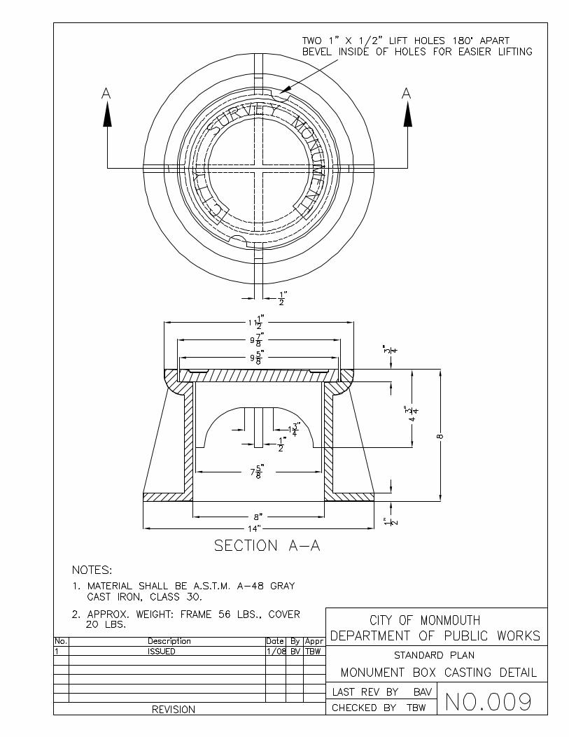


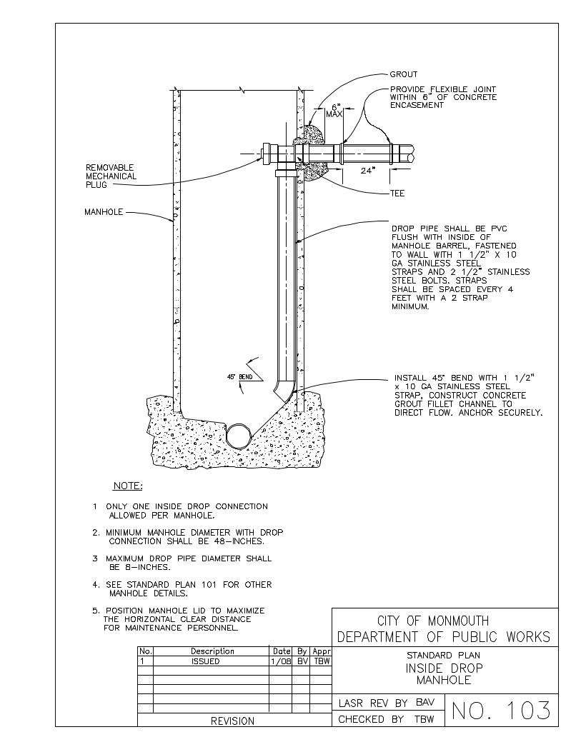
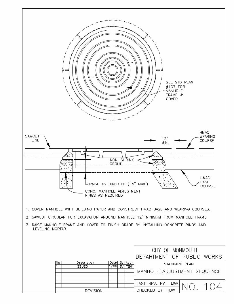


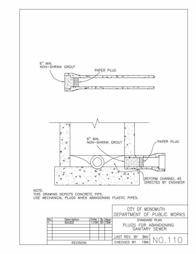


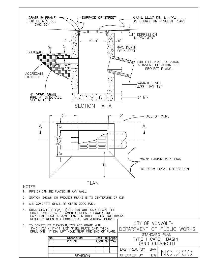


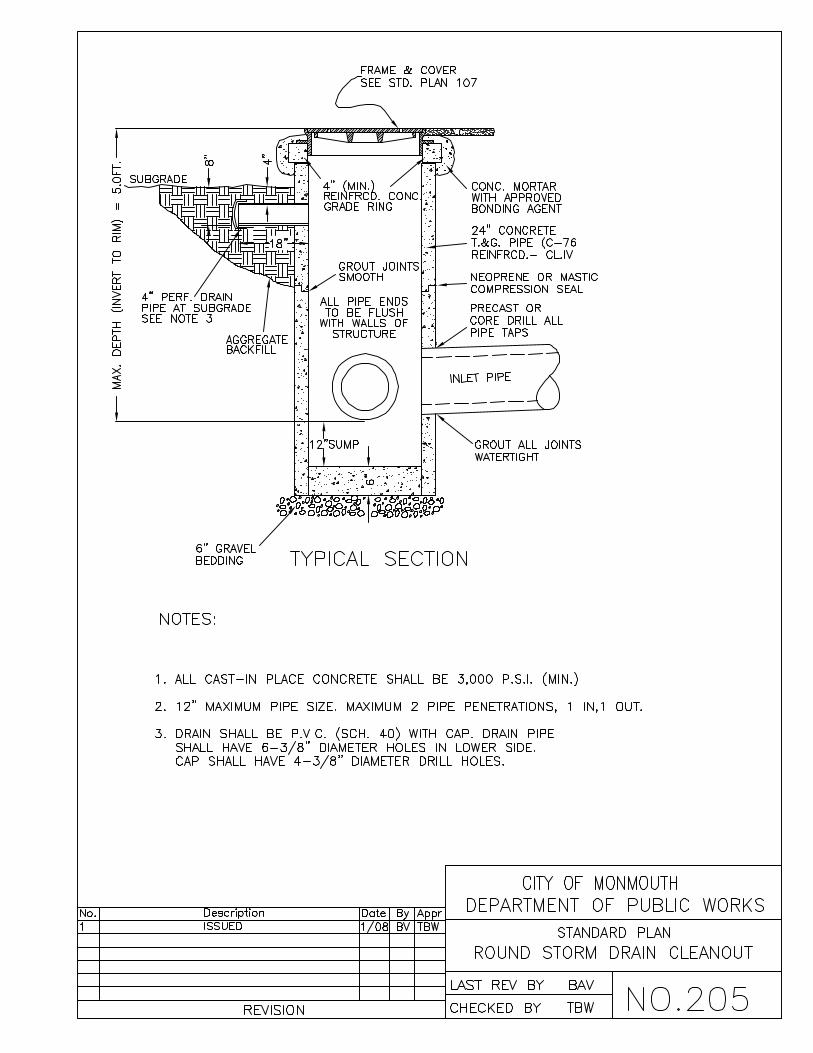
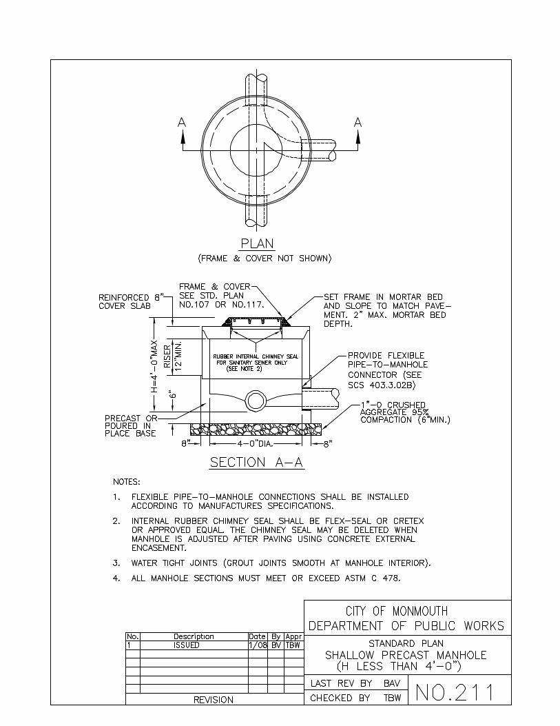
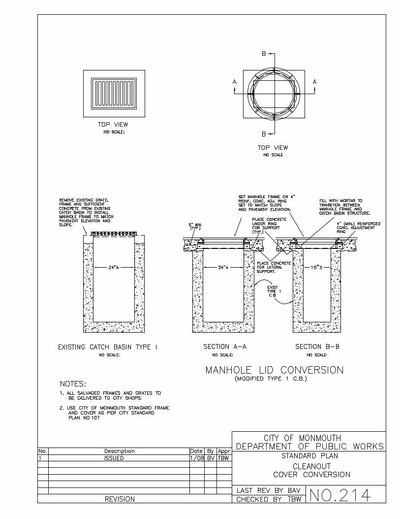
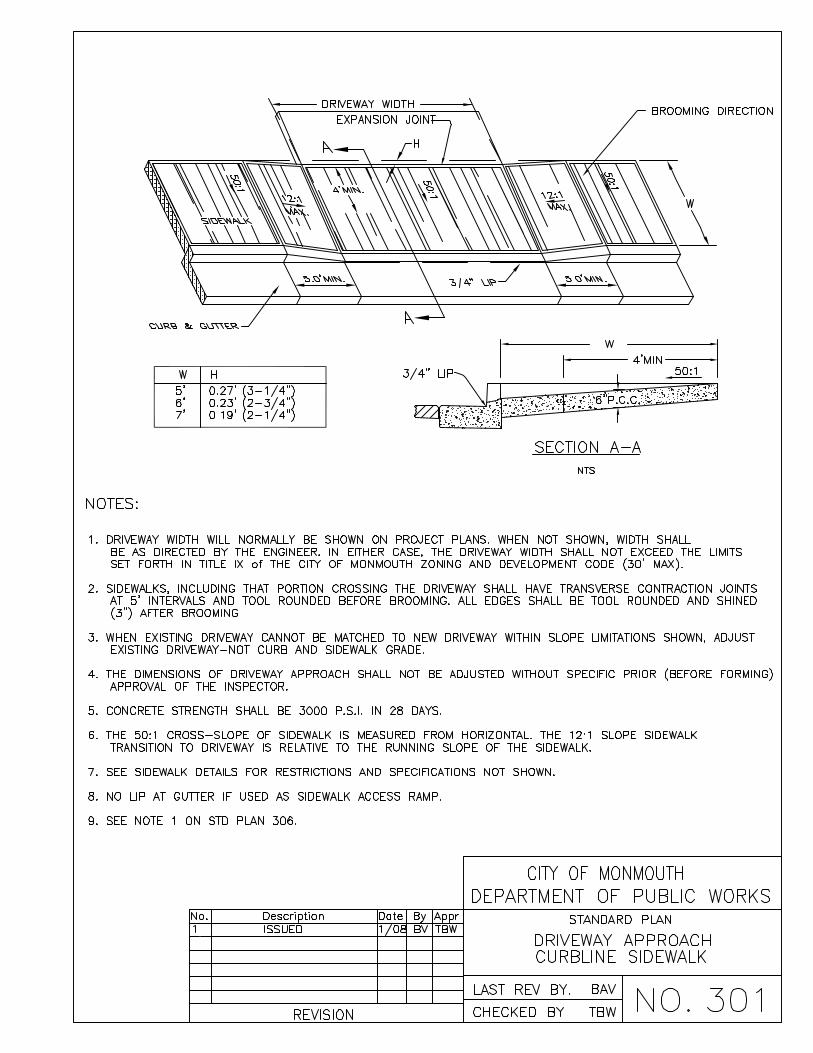
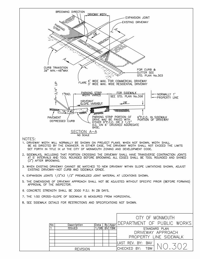


Street Classification
Access Spacing
Right- of-Way Width
(A)
Curb to Curb Width
(B)
Sidewalk Width�
(C)
Bike Lane Width�
On-Street Parking
Planting Strips
Travel Lanes3
Arterial 250 ft.4 84 ft. 60 ft. 6-10 ft.5 2@ 6 ft. each
8 ft bays
7 – 8 ft.6 2@ 10 ft each
Collector 66 ft. 36 ft. N/A� 7 – 8 ft.6 2@ 10 ft each
Residential 66 ft. 36 ft. 5 – 8 ft.5 N/A 7 ft. lanes
7 – 8 ft.6 2@ 10 ft each
Commercial 66 ft. 36 ft. 6 – 10 ft.5 N/A 8 ft. lanes
7 – 8 ft.6 2@ 10 ft each
Industrial other than Arterials
72 ft. 36 ft. 6 – 10 ft.5 Optional 7 ft. lanes
7 – 8 ft.6 2@ 10 ft each
Local 60 ft. 30 ft. 5.0 ft. N/A 2, 7 ft. lanes
7 – 8 ft. 11 – 14 ft. queuing
Circular ends of Cul-de-sacs
114 ft. 80 ft. diam.
5.0 ft. N/A N/A Optional N/A
Alleys 16–20 ft.
12–16 ft.
paved width, 2-4 ft. strips
on both sides
N/A N/A N/A None None
Public Accessways
10–18 ft.
6–10 ft. paved width, 2-4 ft. strips
on both sides
N/A N/A N/A None None
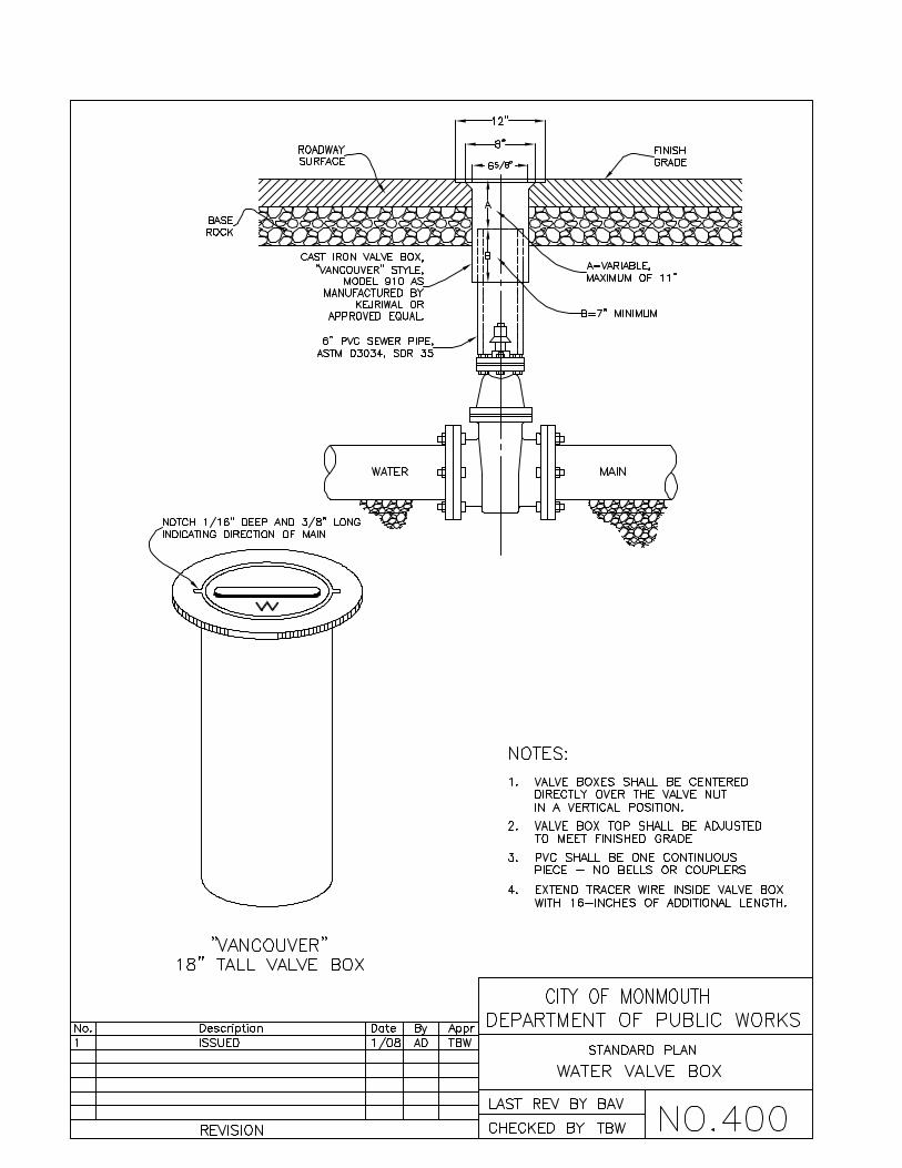
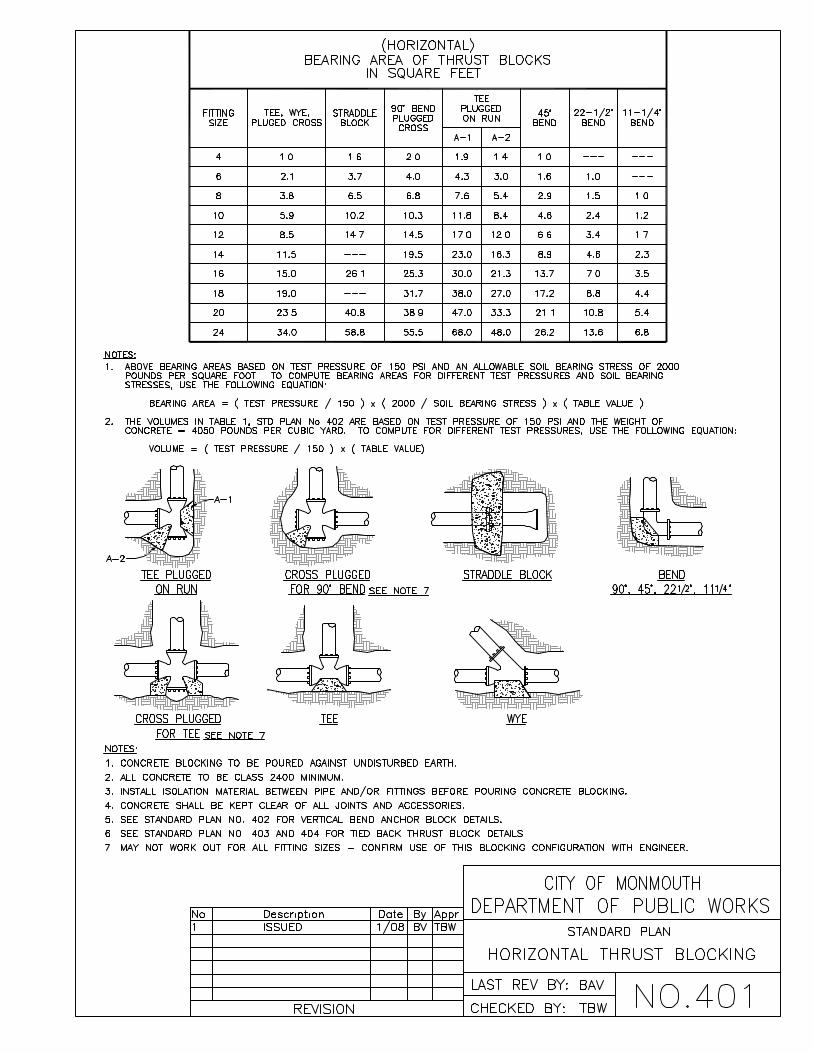


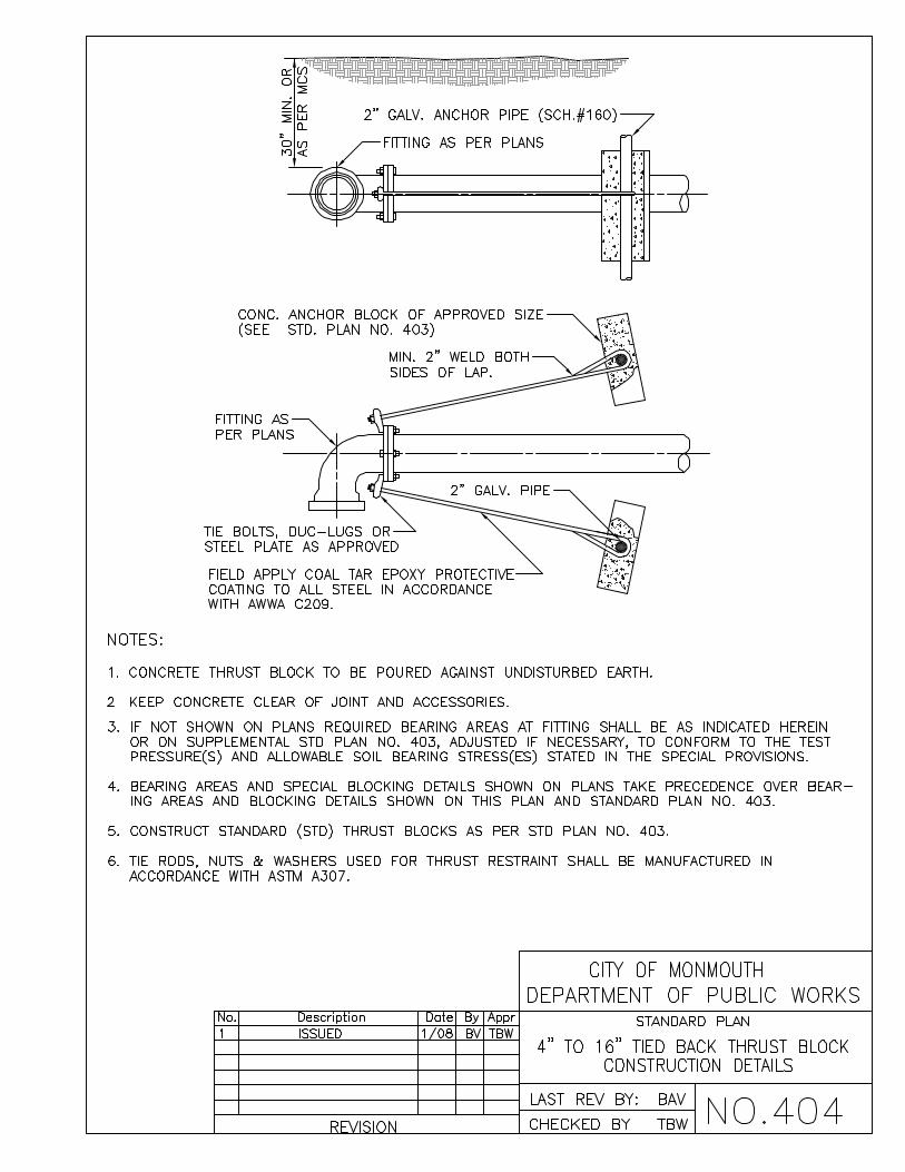


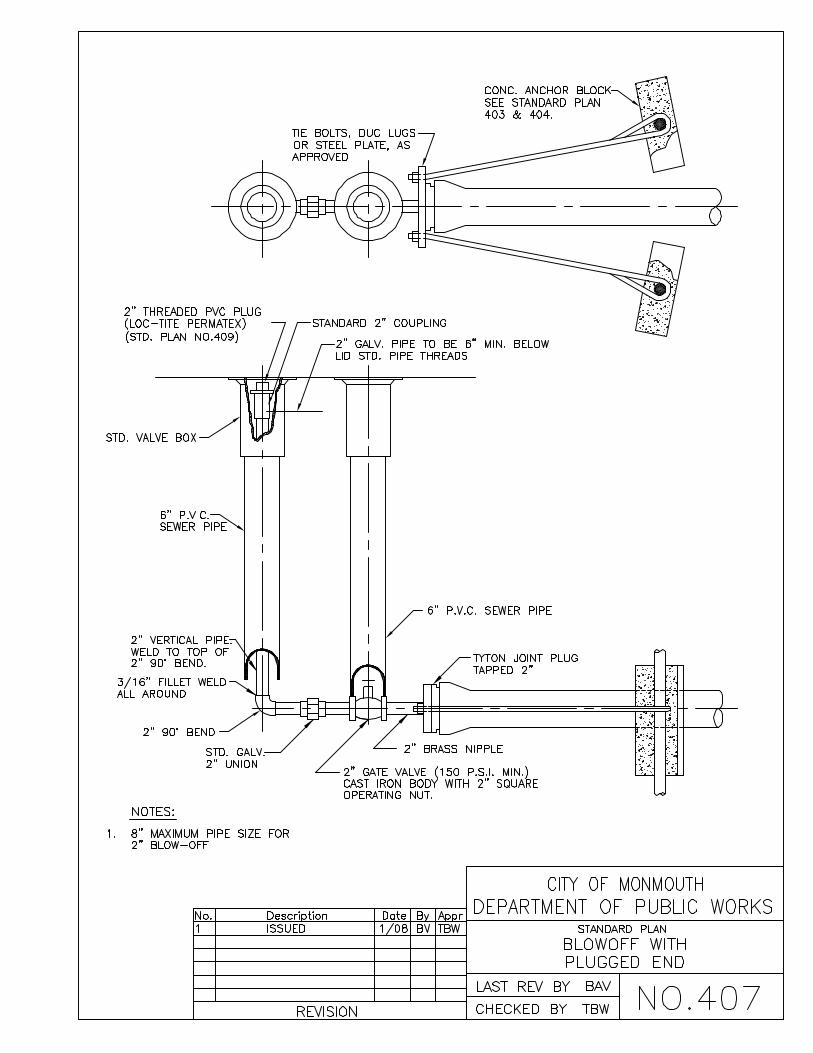
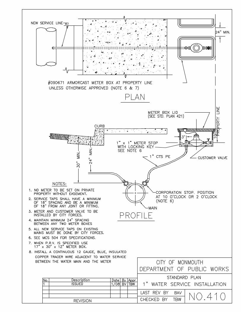


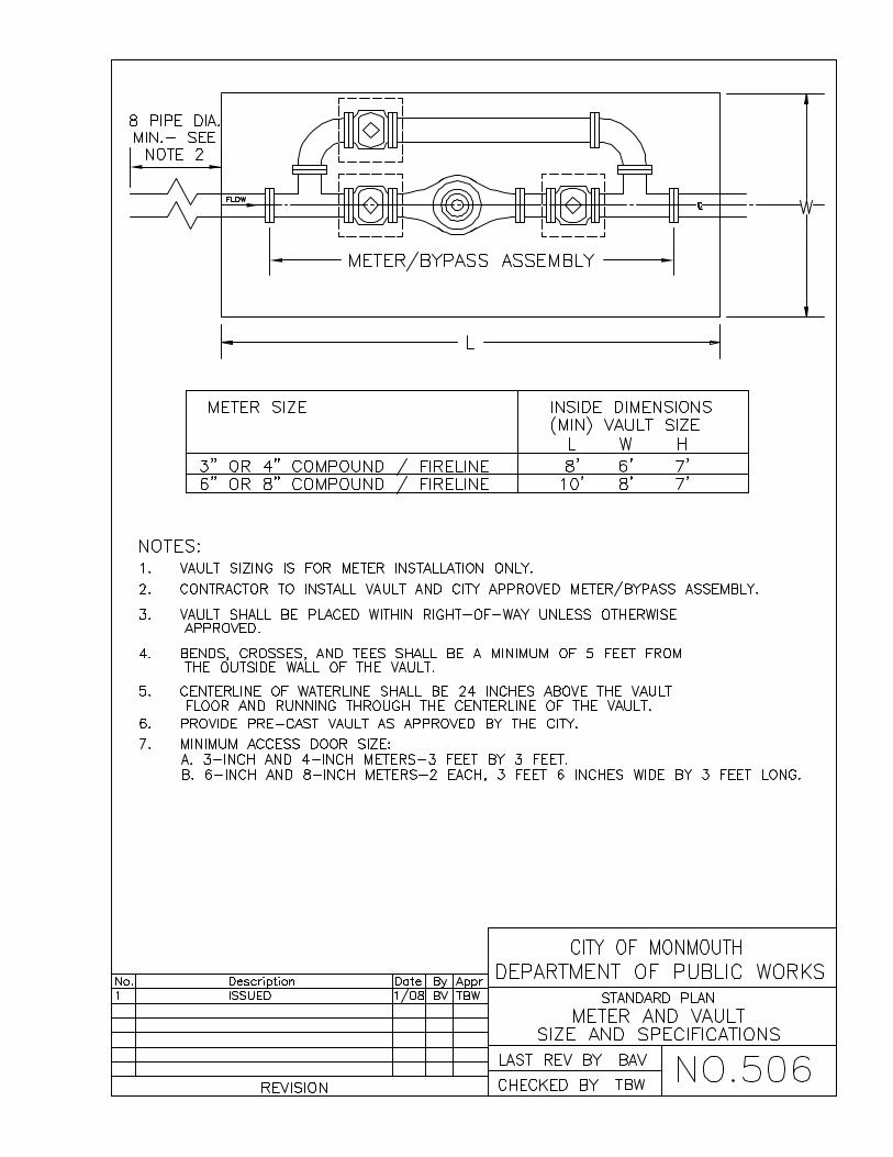


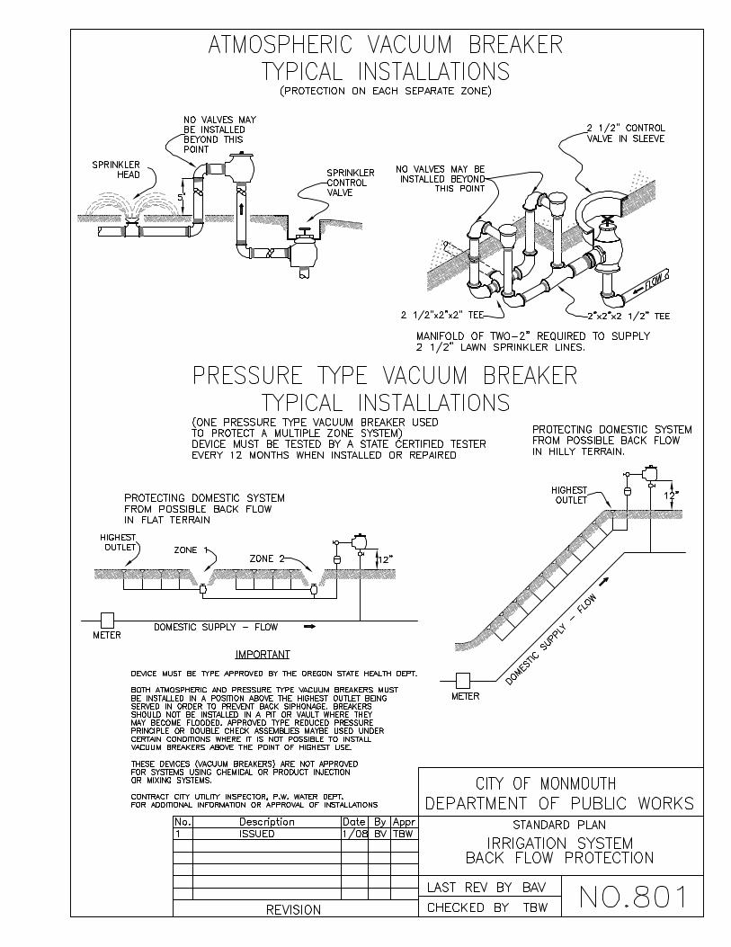


PPPooolllkkk CCCooouuunnntttyyy FFFiiirrreee DDDiiissstttrrriiicccttt ###111
FFFiiirrreee CCCooodddeee AAAppppppllliiicccaaatttiiiooonnnsss GGGuuuiiidddeee
Revised 1/05

2
Preamble/Authority and Scope
The above jurisdiction has elected to administer and enforce the Oregon Fire Code under the authority granted to them by ORS 476.030 or ORS 476.060. The Oregon Fire Code is the International Fire Code, 2003 Edition, as published and copyrighted by the International Code Council, which has been amended and adopted by the Oregon State Fire Marshal's Office.
The above jurisdiction has prepared this Applications Guide to provide good faith guidance to building officials, contractors, business owners, and the public on local interpretations and practices that are considered to be in compliance with the Oregon Fire Code. The intent is to clarify aspects of the code that are vague or non-specific by addressing selected issues under normal conditions. The reader is cautioned that the guidance detailed in this Applications Guide may or may not apply to their specific situation, and that the designated authority for each jurisdiction retains final authority to determine compliance.
Jurisdiction Contact Information
Polk County Fire District No. 1 1800 Monmouth St. Independence, OR 97351 Ph. 503.838.1510 Fax 503.838.1235 Fire Marshal Jason Cane [email protected]

3
Table of Contents Fire Apparatus Access..................................................................................................................... 4 Access Road Distance from Buildings ................................................................................................................ 4
Dead-End Roads & Turnarounds ........................................................................................................................ 4
Turnouts............................................................................................................................................................... 4
Multiple Access Roads Required......................................................................................................................... 4
Multiple Access Road Separation........................................................................................................................ 5
Width & Vertical Clearance.................................................................................................................................. 5
Aerial Fire Apparatus Road Width....................................................................................................................... 5
Surface & Load Capacities .................................................................................................................................. 5
Bridges................................................................................................................................................................. 5
Turning Radius .................................................................................................................................................... 5
Grade................................................................................................................................................................... 5
Gates ................................................................................................................................................................... 6
No Parking Signs................................................................................................................................................. 6
Painted Curbs ...................................................................................................................................................... 6
Firefighting Water Supplies.............................................................................................................. 6 Commercial Building Fire Flow............................................................................................................................ 6
Single-Family Dwelling Fire Flow ........................................................................................................................ 6
Rural & Suburban Dwelling Fire Flow.................................................................................................................. 6
Access and Water Supply During Construction .................................................................................................. 6
Fire Hydrants ................................................................................................................................... 7 Fire Hydrants for Commercial Buildings.............................................................................................................. 7
Fire Hydrants for One- and Two-Family Dwellings.............................................................................................. 7
Fire Hydrant Distribution & Spacing .................................................................................................................... 7
Existing Fire Hydrants ......................................................................................................................................... 7
Non-Threaded Quick Connectors........................................................................................................................ 8
Hydrant Distance from Access Road................................................................................................................... 8
Reflective Markers............................................................................................................................................... 8
Hydrant & Fire Department Connection Proximity .............................................................................................. 8
Key Boxes ....................................................................................................................................... 8 Required Key Boxes............................................................................................................................................ 8
Smoke and Heat Vents Manual Releases................................................................................................................................................. 8
Fire Watch ....................................................................................................................................... 9 Fire Watch ........................................................................................................................................................... 9
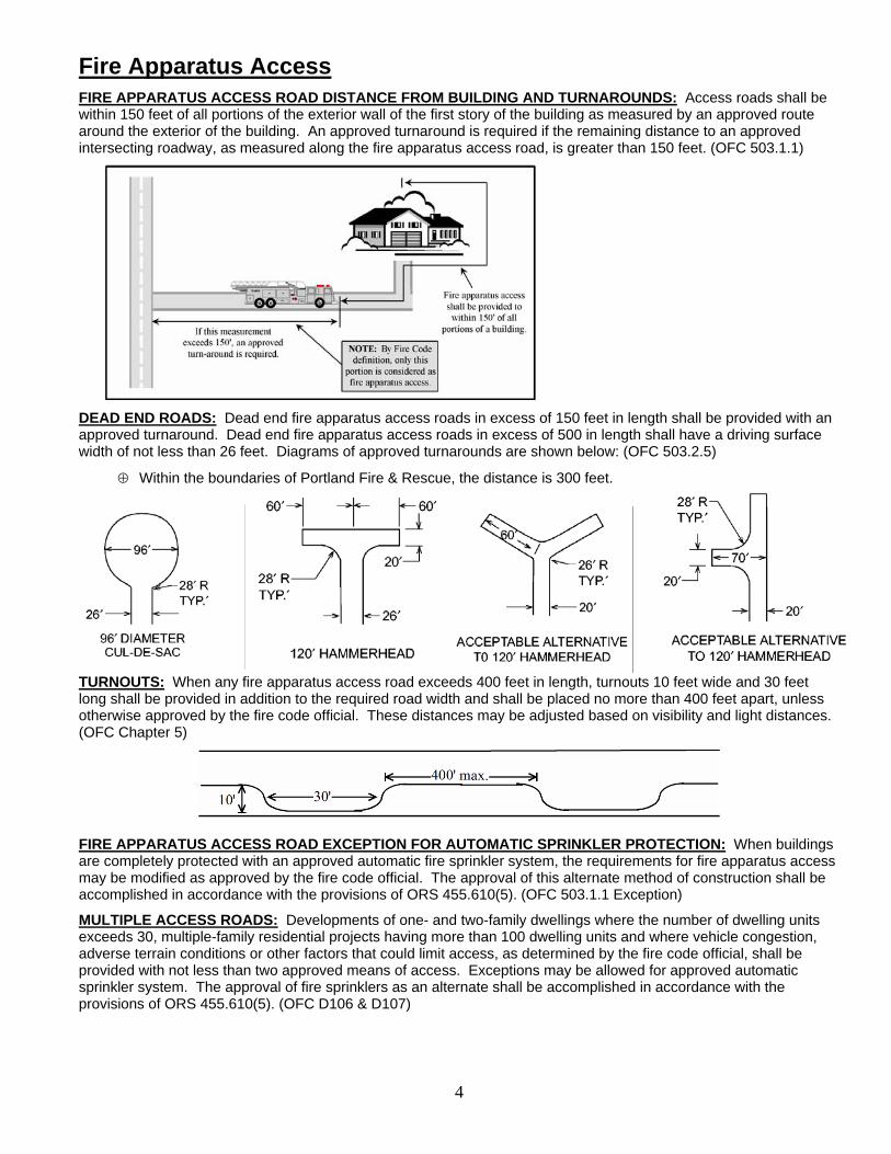
4
Fire Apparatus Access
FIRE APPARATUS ACCESS ROAD DISTANCE FROM BUILDING AND TURNAROUNDS: Access roads shall be within 150 feet of all portions of the exterior wall of the first story of the building as measured by an approved route around the exterior of the building. An approved turnaround is required if the remaining distance to an approved intersecting roadway, as measured along the fire apparatus access road, is greater than 150 feet. (OFC 503.1.1)
DEAD END ROADS: Dead end fire apparatus access roads in excess of 150 feet in length shall be provided with an approved turnaround. Dead end fire apparatus access roads in excess of 500 in length shall have a driving surface width of not less than 26 feet. Diagrams of approved turnarounds are shown below: (OFC 503.2.5)
⊕ Within the boundaries of Portland Fire & Rescue, the distance is 300 feet.
TURNOUTS: When any fire apparatus access road exceeds 400 feet in length, turnouts 10 feet wide and 30 feet long shall be provided in addition to the required road width and shall be placed no more than 400 feet apart, unless otherwise approved by the fire code official. These distances may be adjusted based on visibility and light distances. (OFC Chapter 5)
FIRE APPARATUS ACCESS ROAD EXCEPTION FOR AUTOMATIC SPRINKLER PROTECTION: When buildings are completely protected with an approved automatic fire sprinkler system, the requirements for fire apparatus access may be modified as approved by the fire code official. The approval of this alternate method of construction shall be accomplished in accordance with the provisions of ORS 455.610(5). (OFC 503.1.1 Exception)
MULTIPLE ACCESS ROADS: Developments of one- and two-family dwellings where the number of dwelling units exceeds 30, multiple-family residential projects having more than 100 dwelling units and where vehicle congestion, adverse terrain conditions or other factors that could limit access, as determined by the fire code official, shall be provided with not less than two approved means of access. Exceptions may be allowed for approved automatic sprinkler system. The approval of fire sprinklers as an alternate shall be accomplished in accordance with the provisions of ORS 455.610(5). (OFC D106 & D107)

5
MULTIPLE ACCESS ROADS SEPARATION: Where two access roads are required, they shall be placed a distance apart equal to not less than one half of the length of the maximum overall diagonal dimension of the property or area to be served, measured in a straight line between accesses. (OFC D104.3 & D107.1)
FIRE APPARATUS ACCESS ROAD WIDTH AND VERTICAL CLEARANCE: Fire apparatus access roads shall have an unobstructed driving surface width of not less than 20 feet (26 feet adjacent to fire hydrants (OFC D103.1)) and an unobstructed vertical clearance of not less than 13 feet 6 inches. (OFC 503.2.1 & D103.1)
Note: When serving two or less dwelling units and accessory buildings, the driving surface may be reduced to 12 feet, although the unobstructed width shall be 20 feet. Turning radii for curves and turnarounds on reduced width roads shall be not less than 28 feet and 48 feet respectively, measured from the same center point.
AERIAL FIRE APPARATUS ROAD WIDTH: Buildings more than 30 feet in height shall have fire apparatus access roads constructed for use by aerial apparatus with an unobstructed driving surface width of not less than 26 feet. (OFC D105.2)
SURFACE AND LOAD CAPACITIES: Fire apparatus access roads shall be of an all-weather surface that is easily distinguishable from the surrounding area and is capable of supporting not less than 12,500 pounds point load (wheel load) and 75,000 pounds live load (gross vehicle weight). Documentation from a registered engineer that the finished construction is in accordance with the approved plans or the requirements of the Fire Code may be requested. (OFC D102.1)
BRIDGES: Private bridges shall be designed and constructed in accordance with the State of Oregon Department of Transportation and American Association of State Highway and Transportation Officials Standards Standard Specification for Highway Bridges. A building permit shall be obtained for the construction of the bridge if required by the building official of the jurisdiction where the bridge is to be built. The design engineer shall prepare a special inspection and structural observation program for approval by the building official. The design engineer shall give in writing final approval of the bridge to the fire district after construction is completed. Maintenance of the bridge shall be the responsibility of the party(ies) that use(s) the bridge for access to their property(ies). The fire district may at any time, for due cause, ask that a registered engineer inspect the bridge for structural stability and soundness at the expense of the property owner(s) the bridge serves. (OFC 503.2.6)
TURNING RADIUS: The inside turning radius and outside turning radius shall be not less than 28 feet and 48 feet respectively, measured from the same center point. (OFC 503.2.4 & Appendix D*)
GRADE: Fire apparatus access roadway grades shall not exceed 10 percent. Intersections and turnarounds shall be level (maximum 5%) with the exception of crowning for water run-off. When fire sprinklers are installed, a maximum grade of 15% may be allowed. The approval of fire sprinklers as an alternate shall be accomplished in accordance with the provisions of ORS 455.610(5). (OFC D103.2)

6
GATES: Gates securing fire apparatus roads shall comply with all of the following: (OFC D103.4) ⊕ Minimum unobstructed width shall be 16 feet, or two 10-foot sections with a center post or island. ⊕ Gates serving one- or two-family dwellings shall be a minimum of 12 feet in width. ⊕ Gates shall be set back at minimum of 30 feet from the intersecting roadway. ⊕ Gates shall be of the swinging or sliding type. ⊕ Manual operation shall be capable by one person. ⊕ Electric gates shall be equipped with a means for operation by fire distirct personnel. ⊕ Locking devices shall be approved.
NO PARKING SIGNS: Where fire apparatus roadways are not of sufficient width to accommodate parked vehicles and 20 feet of unobstructed driving surface, “No Parking” signs shall be installed on one or both sides of the roadway and in turnarounds as needed. Roads 26 feet wide or less shall be posted on both sides as a fire lane. Roads more than 26 feet wide to 32 feet wide shall be posted on one side as a fire lane.
Signs shall read “NO PARKING - FIRE LANE” and shall be installed with a clear space above grade level of 7 feet. Signs shall be 12 inches wide by 18 inches high and shall have red letters on a white reflective background. (OFC D103.6)
PAINTED CURBS: Where required, fire apparatus access roadway curbs shall be painted red and marked “NO PARKING, FIRE LANE” at approved intervals. Lettering shall have a stroke of not less than one inch wide by six inches high. Lettering shall be white on red background. (OFC 503.3)
Firefighting Water Supplies
COMMERCIAL BUILDINGS - FIRE FLOW: The minimum fire flow and flow duration for buildings other than one- and two-family dwellings shall be determined according to OFC Appendix B*. The required fire flow for a building shall not exceed the available GPM in the water delivery system at 20 psi.
SINGLE FAMILY DWELLINGS - REQUIRED FIRE FLOW: The minimum available fire flow for single family dwellings and duplexes served by a municipal water supply shall be 1,000 gallons per minute. If the structure(s) is (are) 3,600 square feet or larger, the required fire flow shall be determined according to OFC Appendix B*. (OFC B105.1)
RURAL/SUBURBAN BUILDINGS - REQUIRED FIRE FLOW: Required fire flow for rural and suburban areas in which adequate and reliable water supply systems do not exist may be calculated in accordance with National Fire Protection Association Standard 1142, 2001 Edition, when approved by the fire code official. Please contact the Fire Marshal’s Office for special assistance and other requirements that may apply. (OFC B103.3)
ACCESS AND FIRE FIGHTING WATER SUPPLY DURING CONSTRUCTION: Approved fire apparatus access roadways and fire fighting water supplies shall be installed and operational prior to any combustible construction or storage of combustible materials on the site. (OFC 501.4)

7
Fire Hydrants
FIRE HYDRANTS – COMMERCIAL BUILDINGS: Where a portion of the building is more than 400 feet from a hydrant on a fire apparatus access road, as measured in an approved route around the exterior of the building, on-site fire hydrants and mains shall be provided. (OFC 508.5.1)
Note: This distance may be increased to 600 feet for buildings equipped throughout with an approved automatic sprinkler system.
FIRE HYDRANTS – ONE- AND TWO-FAMILY DWELLINGS & ACCESSORY STRUCTURES: Where a portion of a structure is more than 600 feet from a hydrant on a fire apparatus access road, as measured in an approved route around the exterior of the structure(s), on-site fire hydrants and mains shall be provided. (OFC 508.5.1)
FIRE HYDRANT NUMBER AND DISTRIBUTION: The minimum number and distribution of fire hydrants available to a building shall not be less than that listed in Table C 105.1. See page 9 for hydrant proximity to FDC. (OFC Appendix C*)
TABLE C105.1 NUMBER AND DISTRIBUTION OF FIRE HYDRANTS
FIRE-FLOW REQUIREMENT (gpm)
MINIMUM NUMBER OF HYDRANTS
AVERAGE SPACING BETWEEN HYDRANTSa, b, c
(feet)
MAXIMUM DISTANCE FROM ANY POINT ON STREET OR ROAD
FRONTAGE TO A HYDRANTd 1,750 or less 1 500 250
2,000-2,250 2 450 225
2,500 3 450 225
3,000 3 400 225
3,500-4,000 4 350 210
4,500-5,000 5 300 180
5,500 6 300 180
6,000 6 250 150
6,500-7,000 7 250 150
7,500 or more 8 or moree 200 120
For SI: 1 foot = 304.8 mm, 1 gallon per minute = 3.785 L/m. a. Reduce by 100 feet for dead-end streets or roads. b. Where streets are provided with median dividers which can be crossed by fire fighters pulling hose lines, or where arterial streets are provided with
four or more traffic lanes and have a traffic count of more than 30,000 vehicles per day, hydrant spacing shall average 500 feet on each side of the street and be arranged on an alternating basis up to a fire-flow requirement of 7,000 gallons per minute and 400 feet for higher fire-flow requirements.
c. Where new water mains are extended along streets where hydrants are not needed for protection of structures or similar fire problems, fire hydrants shall be provided at spacing not to exceed 1,000 feet to provide for transportation hazards.
d. Reduce by 50 feet for dead-end streets or roads. e. One hydrant for each 1,000 gallons per minute or fraction thereof
Considerations for placing fire hydrants may be as follows: (OFC C104)
⊕ Existing hydrants in the area may be used to meet the required number of hydrants as approved. Hydrants that are up to 600 feet away from the nearest point of a subject building that is protected with fire sprinklers may contribute to the required number of hydrants. (OFC 508.5.1)
⊕ Hydrants that are separated from the subject building by railroad tracks shall not contribute to the required number of hydrants unless approved by the fire code official.
⊕ Hydrants that are separated from the subject building by divided highways or freeways shall not contribute to the required number of hydrants. Heavily traveled collector streets only as approved by the fire code official.
⊕ Hydrants that are accessible only by a bridge shall be acceptable to contribute to the required number of hydrants only if approved by the fire code official.
⊕ When evaluating the placement of hydrants at apartment or industrial complexes the first hydrant(s) to be placed shall be at the primary access and any secondary access to the site. After these hydrants have been placed other hydrants shall be sited to meet the above requirements for spacing and minimum number of hydrants.

8
FIRE HYDRANT NON-THREADED QUICK CONNECTORS: Non-threaded quick connectors shall be installed on all newly installed fire hydrants in the following jurisdictions:
Polk County Fire District No. 1
FIRE HYDRANT DISTANCE FROM AN ACCESS ROAD: Fire hydrants shall be located not more than 15 feet from an approved fire apparatus access roadway unless approved by the fire code official. (OFC C102.1)
REFLECTIVE HYDRANT MARKERS: Fire hydrant locations shall be identified by the installation of reflective markers. The markers shall be blue. They shall be located adjacent and to the side of the centerline of the access road way that the fire hydrant is located on. In case that there is no center line, then assume a centerline, and place the reflectors accordingly. (OFC 508.5.4)
FIRE HYDRANT/FIRE DEPARTMENT CONNECTION: A fire hydrant shall be located within 100 feet of a fire department connection (FDC). Fire hydrants and FDC’s shall be located on the same side of the fire apparatus access roadway. (OFC C102.1 & NFPA 14)
FDCs shall normally be remote except when approved by the fire code official.
Key Boxes
KEY BOX: A key box for building access may be required. Please contact the local Fire Marshal’s Office for an order form and instructions regarding installation and placement. (OFC 506)
Smoke and Heat Vents MANUAL RELEASE: Manual releases shall be provided for use during fire suppression operations. Individual exterior release mechanisms shall be provided for each vent.

9
Fire Watch
FIRE WATCH: Whenever a required fire alarm, detection or suppression system is out-of-service and a life hazard and or distinct fire hazard is present, the fire code official and/or the property owner or manager shall initiate a fire watch. A fire watch is defined as a temporary measure intended to ensure continuous and systematic surveillance of a building or portion thereof by one or more qualified individuals for the purposes of identifying and controlling fire hazards, detecting early signs of unwanted fire, raising an alarm of fire and notifying the fire department. Each affected area or building must be patrolled hourly and documented on a written log. Individuals assigned to fire watch duty must be provided with a means of communication such as a cell phone or two-way radio and their only duties shall be to perform constant patrols. The watch must remain in effect until repairs are made and the system(s) are back in-service. When in doubt if a system is required or if a fire watch is needed, contact the local Fire Marshal’s Office for consultation and or response. (OFC, Section 901.7 & Section 202) EXAMPLES: The automatic smoke detection system in the Family Birth Center at the local Hospital is taken off-line due to unwanted false alarms and an alarm technician has been dispatched to evaluate the system. This is a required detection system and the patients occupy the floor. A fire watch is required and could be conducted by nursing and or security personnel. The manual fire alarm system at a local Elementary School is initiating false alarms and is taken off line by school district personnel; the automatic smoke detection and fire sprinkler system are operational. It’s Saturday afternoon and the building is not occupied. Although this is a required system, a fire watch is not required as the building is vacant. The water main that serves a local apartment complex is damaged in a construction accident rendering the fire hydrants and residential fire sprinkler systems out-of-service. It’s Sunday night and nearly all of the apartments are occupied. Both systems are required and a continuous fire watch is needed. *Oregon Fire Code Appendices B, C, and D referenced in this guide can be viewed by going to the link below. http://www2.iccsafe.org/states/oregon/07_Fire/Fire07_Frameset.htm