city of golden pv evaluation
TRANSCRIPT

City of Golden PV Evaluation
Prepared for:
City of Golden
Prepared by:
Golden Solar Solutions Jessica Ellis, Saltanat Kassymgaliyeva,
William Simpson, Zachary Simpson, Paul Slade
Preliminary Design Report
November 17th, 2020

City of Golden PV Evaluation
TABLE OF CONTENTS
1.0 Executive Summary
2.0 Introduction
3.0 Background, Boundaries, Characteristics
3.1 Scope of Work
4.0 Design Specifications
4.1 Introduction and List of Specifications
4.2 Specifications
5.0 Concept
5.1 Concept Exploration
5.2 Concept Critique
5.3 Concept Selection
6.0 Next Steps and Conclusion
7.0 Schedule – WBS
8.0 References
Appendices
A.1 Helioscope Models
A.2 CAD Drawings
A.3 WBS
A.4 Client Needs Table
A.5 Stakeholder Map
A.6 Photographs and Illustrations
A.7 Soil Survey Map
A.8 Envision Rating System
EDNS 491/492 – Senior Design page 2

City of Golden PV Evaluation
1.0 Executive Summary
The City of Golden PV Evaluation project involves a solar garden proposal off of Highway 93 and 56th Avenue. Our plan is to construct a two Megawatt solar garden inside of an eighty acre site to provide solar power for the surrounding community in this area of Golden. Our deliverables for this project include a scope of work defining what is to be constructed for this project, as well as specifications including a list of design standards and codes and laws we are following that meet City of Golden requirements. We explore the types of solutions including a fixed versus tracking system and weigh the costs and benefits. These solutions are then critiqued using the Envision Rating System. After critique, and selection, we validate our solution with Helioscope models. We dive into the functional bias with CAD drawings that include the existing conditions of the site, a set of proposed site plans where the solar garden will reside, and Helioscope models that provide a top-down view of the solar panels, and calculations for energy production. For this project our deliverables are summarized into a Work Breakdown Schedule in both tabular and graphical form. The tabular form has each task assigned to a team member and a due date, and the graphical schedule shows each section with subtasks. Included in this report is a list of references and an Appendix including our above mentioned drawings and models, as well as pictures of the proposed site.
2.0 Introduction
The City of Golden Photovoltaic Evaluation is a project the Golden Solar Solutions team has been assigned to in order to perform a feasibility analysis to help achieve the goal of 100% renewable energy by 2030. Our team consists of Paul Slade, a mechanical engineer and communication lead, Zachary Simpson, an electrical engineer and Scrum master, William Simpson, an electrical engineer, Jessica Ellis, a civil engineer, and Saltanat Kassymgaliyeva, an environmental engineer. Individually we have worked on tasks that align with our majors and areas of expertise, and as a team have brought those components together to present the best solution for a community solar garden. Our approach to this project began with a Project Charter which outlined the project overview including a description of the project and initial deliverables, as well as restrictions, exclusions, and assumptions. This document provided a list of our project staff including the client, faculty, and other stakeholders like the City of Golden Sustainability Advisory Board and Xcel Energy. Additionally our project objectives like major milestones and customer needs were broken down into separate documents as our Work Breakdown Structure and Client Needs Table which can be seen in the Appendix, A.3 and A.4. The next step in our project was writing a Letter of Intent summarizing our Project Charter, so our client could approve of the scope of work and provide additional feedback. This letter included a stakeholder map as well which can also be seen in the Appendix, A.5. After approval from our client, we began research on community solar gardens and City of Golden rules and regulations. We had an opportunity to walk the site with our client and get an idea of the land constraints which were considered in our design phase. After research, design considerations, and modeling, our team has determined that a fixed system solar array provides the most feasible solution to maximize the energy production of the two Megawatt community solar garden.
EDNS 491/492 – Senior Design page 3
City of Golden PV Evaluation
3.0 Background, Boundaries, Characteristics
In 2018 the City of Golden adopted a sustainability initiative that requires 100% renewable energy
for electricity by 2030. To aid in this renewable energy transition, the voters in the City of Golden have expressed overwhelming support (81%) for a community solar power generation site. Many
residents are unable to install their own solar generation because of rental housing or other financial limitations. Centralized community solar power would allow residents to subscribe to a
portion of the power generated by the array, making it easier to achieve the 100% renewable
energy by 2030 goal. A fifteen acre decommissioned landfill near Rooney Rd was chosen to accommodate this community solar vision. Due to land use restrictions and financial concerns the
array was never built.
With the Rooney Rd development stalled, the City of Golden chose to lease an eighty acre parcel of land from the State of Colorado with the intent to develop a 2-5 MW array. Clean Energy Collective,
a third party developer, has installed 500 kW on the parcel, demonstrating that solar power is viable for the land. The two year planning lease approved by the State will allow stakeholders to
perform a comprehensive feasibility analysis on the eighty acre parcel. The senior design team,
Golden Solar Solutions, was chosen to evaluate the feasibility of the land and create a conceptual design of the solar array. If the analysis is approved, the City of Golden will extend the lease with
the State of Colorado by twenty years and enter the production phase. The production phase will
allow the City to begin development of the solar array.
3.1 Scope of Work
The project scope is to create a conceptual system design with technical and financial validation for
a large-scale 2 Megawatt community solar photovoltaic array located on a leased parcel in North Golden. The conceptual design will include aerial site plans, spec sheets for selected hardware,
ballpark cost estimates, and a geographical analysis of the 80 acre parcel. The scope also includes a presentation to the Golden Community Sustainability Board and a flyover video simulation of the
conceptual design, if time permits.
The conceptual drawings will show the arrangement of the panels on the plot of land along with the property line. A satellite image will be provided displaying the location of the array with desired measurements. The technical analysis will include a comparison of a single axis tracker versus a fixed tilt system, along with a comparison of domestic versus foreign panels. The analysis will look into the slope of the land and any geographic constraints that need to be considered. The cost estimate will take into account the components used along with the mounting system and interconnection to the grid. Also the overall maintenance costs so the client will understand the cost of the system over time.
4.0 Specifications
4.1 Introduction and List of Specifications
EDNS 491/492 – Senior Design page 4

City of Golden PV Evaluation
The types of specifications made for this project were related mainly to the interconnection and classification of the solar garden. These specifications were made in order to fall under the
guidelines of an Xcel interconnection study and the power range to stay in the utility scale.
4.2 Specifications
The specifications for this project are as follows:
4.2.1 The solar array will not exceed 10MW to keep a Level 3 (Interconnection study) with Xcel energy.
4.2.2 The initial plant will not exceed 5MW to keep the classification of utility grid
community garden.
4.2.3 NFPA 2014 NEC 70 contains an article that restricts the size of an inverter based interconnection into a shared panelboard.
4.2.4 Commercial and industrial districts must observe a five-foot minimum front setback.
4.2.5 Streetscape improvements required as per site development regulations in chapter 18.40 of the Municipal Code.
4.2.6 Ground-mounted solar energy collectors may not be located within utility easements or drainage easements unless authorized in writing by easement holder.
4.2.7 A planning commission finding that the proposal is located to minimize glare on
adjacent properties and roadways.
4.2.8 The rated capacity shall not exceed 500 kW, except that for properties within the R3,
C1, C2, M1, and M2 districts, planning commission may authorize a solar garden with a
rated capacity greater than 500 kW that meets the criteria above and in chapter 18.30, and further provided that the minimum lot size for an installation in the R3 district shall be one
acre.
5.0 Concept
5.1 Concept Exploration
To model different solar array configurations the team used a software called Helioscope. This software takes in weather data provided by the National Renewable Energy Laboratory (NREL) and
loaded component characteristics to simulate power generated by a system. By factoring in the
annual weather patterns it provides a clear estimate of power generation. The modeling software also accounts for shading from nearby trees and geographical features. Golden has 300 days of
sunshine, on average, giving it a huge advantage in generation of solar energy. However, the hilly geography in the region limits the number of hours that the panels will receive sunlight.
Specifically, the hogback to the west of the land will greatly reduce the energy produced by panels
that are too far west.
EDNS 491/492 – Senior Design page 5

City of Golden PV Evaluation
The team selected four different configurations to simulate using Helioscope. The four designs compare the energy production of fixed tilt. vs tracking systems using different hardware
selections. One simulation explores the potential for a mixed use solar system using agrivoltaics.
Concept A: Fixed Tilt 1
The fixed array system is the classic approach to solar energy production. This places the panels in
a set direction along with a fixed slope of the panel for maximum efficiency. A steeper angle of panel is more efficient when the sun is lower in the sky during the winter months. A flatter angle is more
efficient when the sun is higher in the sky during summer months. For a fixed tilt array the latitude location of the array can affect the angle that should be used. In general, a higher latitude requires a
steeper module tilt angle [9]. These arrays are usually oriented South facing to maximize energy
production as the sun moves through the sky during the day.
For concept A the team decided to use a Jinko JKM-580 panel for multiple reasons. First, Jinko has
been on the forefront of efficient and cost effective panel design. While the company is based
overseas in China they have opened a manufacturing facility in the United States. The Jinko JKM-580 panel is 580 watts per panel and that helps the size of the array decrease along with overall
efficiency of the system. Being able to increase the wattage per panel means there is less framing
per watt as there are no cells present on the frame to generate power. This leads to less area being needed for the same energy production. With there being less panels this means fewer connections
between panels along with fewer panels to install, so less work needs to be accomplished on the installation side. The solar industry continues to move in the direction of larger panels and the team
wants to provide a solution that will withstand the test of time and be efficient for the longest
amount of time. A large goal of this senior design project is to create sustainable projects and this is an important step in creating sustainable energy. While there are cheaper alternatives to this panel
they will not last as long and never be as efficient as the panel the team is suggesting.
Concept B: Fixed Tilt 2
While the team was looking into providing a domestic panel it was determined that most of the
United States manufactured panels are for residential use. This led to the team deciding to move forward with the Canadian Solar CS7N-655MB which is a 655 watt solar panel designed for utility
scale applications. Again the team is deciding to go with a new larger capacity panel which provides
the same benefits the Jinko panels provide. This particular panel is a bifacial panel which means it has solar cells on both sides of the panel which helps the panel maximize energy production.
Concept C: Single Axis Tracking
A single axis tracking array is a solar array that tracks the sun during the day so that the array
maximizes the possible solar output. The way this works is by having the panels connected to a motor on their ground mount so that the panels have the ability to rotate. These arrays are usually
configured North-South so that the panels can track and rotate following the sun from sunrise in
the East to sunset in the West. The large benefit of tracking systems is the overall output of the system can increase an average of 20-30 percent. This is very important where there is a space
constraint on the size of the array as the footprint of the area can decrease while keeping the same
EDNS 491/492 – Senior Design page 6

City of Golden PV Evaluation
overall energy output of the system. Overall the cost of the array can increase by up to 20 percent by installing a tracking system. [10]For the tracking system the same components chosen for the
fixed system will be used.
Concept D: Agrivoltaic Array
The concept of the co-development of both solar photovoltaic power and conventional agriculture
is known as agrivoltaics. It is a good opportunity for farmers and solar developers to achieve net benefits. While agrivoltaics might increase the efficiency of the land use, not all soils are sustainable
for growing vegetation. The Web Soil Survey Map through The National Resources Conservation Service website in Appendix A.7 shows that the area of installation of solar panels in helioscope
models have map unit symbol 173 that corresponds to cobbly sandy loam with 0 to 5 percent slope.
Sandy loam type of soil is known for high infiltration rate (20-30 mm/hr) that leads to quick drainage of water into soil. It significantly decreases the chances of flooding or overland-flow
during heavy rain and snow melt seasons. However, compared to clay and silt soils, sandy loam soil
will dry quickly not allowing plants to absorb the necessary amount of nutrients. This leads to frequent need of irrigation and fertilization of the land. Compared to other helioscope models, the
agrivoltaic solar arrays are located in distance and, thus, produce less power.
Inverter Selection
All of the above concepts were simulated using the same inverter. The team decided to work with a
newer type of solar inverter which is the Solectric XGI 1500. An efficient inverter is a key component in a solar array as it converts the direct current of the solar array into alternating
current which is used on the grid. For this project no battery system was required as the team is using the grid as a battery. This means that the solar array will be producing energy and putting it
on the grid directly and then Xcel energy will be able to determine the amount of energy from the
community solar garden to take off the subscriber’s energy bill. The Solectria XGI is a 1500 volt inverter which is an increase from the previous standard of 1000 volts. When generating and
moving electricity at higher voltages the current in the line is lower. When the current is lower the
electricity losses due to resistance are also decreased, leading to a higher overall efficiency of the system. With the larger inverter there are also fewer inverters to purchase and connect to the array.
This brand of inverter is a standard in industry and was recommended by Grid Alternatives, a local
solar installer based out of Denver. Grid Alternatives has years of experience designing, developing and installing large scale arrays.
Technical Validation
To show the differences in each of the provided options the team will discuss how each option
varies in the Helioscope model.
Concept A
First the team worked with a standard fixed tilt system using the Jinko panel and Solectria inverter.
Below you can see the layout of the panels along with the placement of the electrical inverters.
EDNS 491/492 – Senior Design page 7

City of Golden PV Evaluation
While experimenting inside of the software it was determined peak production would occur at a tilt angle of 22 degrees. The Helioscope model is shown below in Figure 1.
Figure 1: Fixed Jinko Panel Model
The above model shows the exact layout of the panel and the size of an array necessary to generate
2 Megawatts of energy. The array is set with 10ft spacing between rows to allow for easy access to
the panels for maintenance. The team also plans to have a fence around the array that is set 10 feet away from the array which is standard. Below in Figure 2 shows the monthly solar production for
Concept A.
Figure 2: Monthly Solar Power (kWH) Production For Jinko Panel
EDNS 491/492 – Senior Design page 8

City of Golden PV Evaluation
As shown in the monthly solar power production table the summer months of course generate a much larger amount of power due to the amount of sunshine per day being considerably longer.
The array was designed to be this size as it will accommodate for the needs in the winter months
while providing extra energy in the summer. With this increase in energy production, the City of Golden could use this energy to power municipal buildings or sell the energy back to Xcel Energy.
Also the system is sized as a 2.5 Megawatt system on the DC side to account for the losses through inverting and therefore having a 2 Megawatt AC system. This system will be the most affordable as
fixed tilt is the standard for commercial scale arrays with a standard monofacial panel.
Concept B
The team then tested the effects of introducing a domestic bifacial panel to experiment on the
amount of energy produced. The model had a very similar footprint to Concept A therefore a picture was not included. Below in Figure 3 is the monthly solar production using the Canadian Solar panel.
Figure 3: Monthly Solar Power (kWH) Production For Canadian Solar Panel
While the Canadian Solar offers a similar product to Jinko it is seen in the production charts that it is not as efficient as the Jinko option. This means the overall production from the array will be
decreased. A possible reason for this could be the fact that the modeling software does not have the true ability to model bifacial panels. This explains some of the discrepancies with this panel being
advertised as a 655 watt panel and the energy production still decreasing. The way a bifacial panel
functions is by picking up solar that is reflected from the ground the panels are mounted on top of. The bifacial panel functions better at a steeper angle which does not suit the teams design and the
location of the array. Also a bifacial panel is more expensive than a traditional monofacial panel and
has installation challenges.
Concept C
Next the team introduced a single axis tracking system with the Jinko panels. The Helioscope model is seen below in Figure 4.
EDNS 491/492 – Senior Design page 9

City of Golden PV Evaluation
Figure 4: Tracking Jinko Panel Model
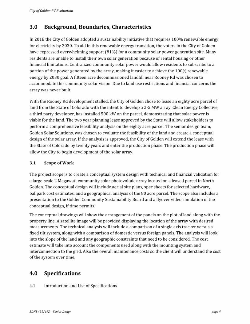
The Helioscope model shows that for tracking the array is oriented North-South which gives the
ability to track the sun throughout the day. The footprint is marginally smaller than the fixed tilt array. This is due to an increase in production per panel by tracking. Tracking can greatly increase
the amount of energy produced if in the right location. Below in Figure 5 shows the tracking
systems monthly energy production.
EDNS 491/492 – Senior Design page 10

City of Golden PV Evaluation
Figure 5: Monthly Solar Power (kWH) Production For Tracking System
While a tracking system can greatly increase the amount of energy produced and satisfy the typical
energy needs with a slightly smaller footprint it is mostly effective in the summer months. The
array sees dramatic increases in the production during the summer months but with less panels lacks the energy needed in December. A tracking system can help to get the most out of a plot of
land for solar when space is limited. Along with an open horizon so the system can track from
sunrise to sunset is very important. Looking at the location of this array the horizon consists of hills on both sides limiting the full potential of a tracking system. As the amount of land for this array is
not a real limiting factor along with the added cost of a tracking system it is not imperative to have a
tracking system for this array.
Concept D
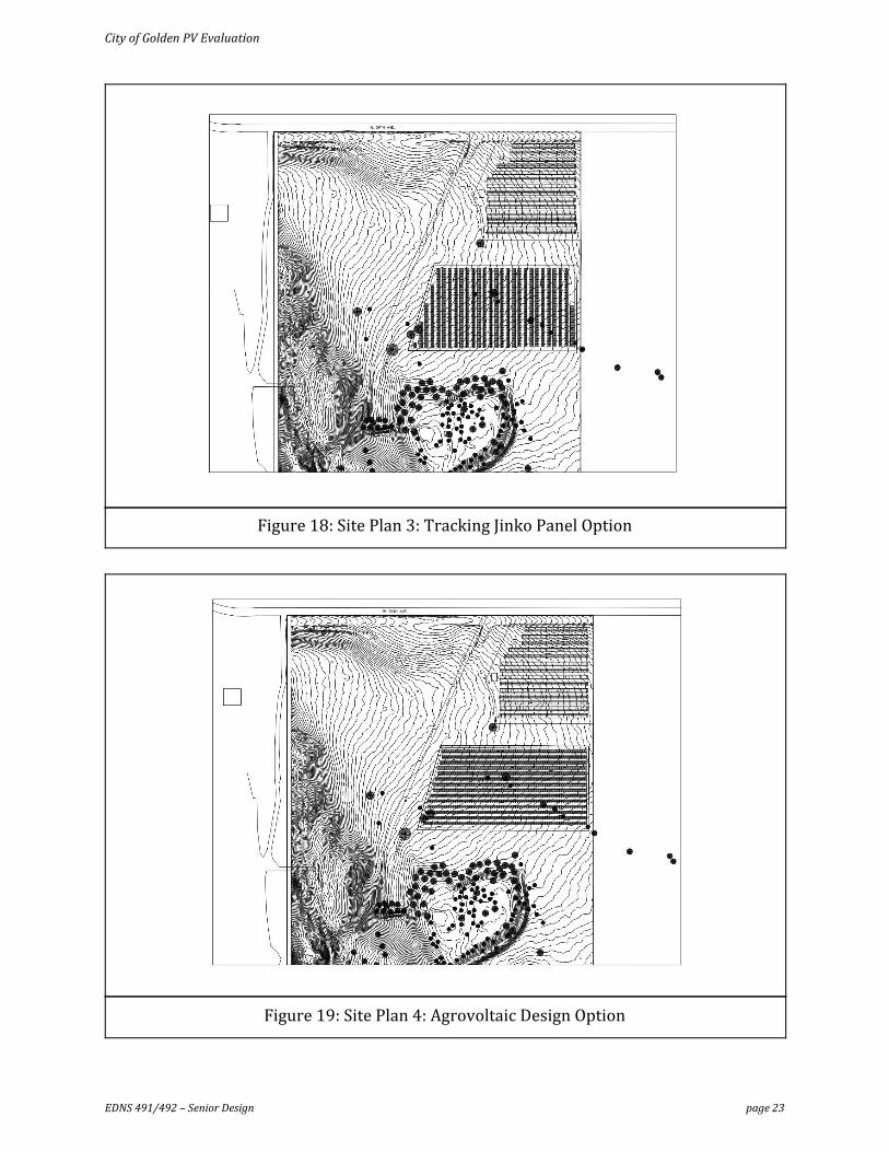
The client was interested in the possibility of having the land be multi use which agrovoltaics is able to accomplish. The land around the array can be used for agricultural use. Below in Figure 6 shows
the layout of an agrivoltaic array.
Figure 6: Agrivoltaic Design
EDNS 491/492 – Senior Design page 11

City of Golden PV Evaluation
As it is seen in the Helioscope model while using the same footprint as the fixed tilt array the physical space for the panels are decreased. This is to accommodate for the space needed between
panels which assists in making the land around the array usable by having more sunlight pass
through it. There is currently no standard on the most efficient way to design an agrivoltaic array so this model serves as an example of a possible solution. In Figure 7 below the energy production per
month is shown.
Figure 7:Monthly Solar power (kWH) Production For Agrivoltaic Design
Compared to the other designs the agrivoltaic design produces a lower overall power production.
This is partly due to the losses which are increased due to the wiring and shading of these systems. Another reason is to show how while using the same size footprint for the array the overall output
will decrease with this model. The agrivoltaic design must account for space in between panels to let sunlight through along with higher racking to allow for more space below the panel. This design
increases the need for space due to gaps in between panels along with costs as the higher racking
mounts that are needed.
Along with the above described Helioscope models, AutoCAD drawings were created to integrate
these models and present the existing topography of the land. Figure 14 in Appendix A.2 shows the
existing conditions of the site including roads, trees and shrubs, and houses both inside and outside of the property line. The contours shown are taken from the response to the 2013 Colorado Flood
done by Denver Regional Council of Governments (DRCOG) [11]. Using this data, a 3D model was
created, shown as Figure 15 in Appendix A.2. Figures 16-20 also in Appendix A.2 combine the existing conditions of the site and the Helioscope models to present five different site plans for each
option. The incorporation of these two softwares allows us to calculate the slopes of the existing ground where the panels will be located.
Ground Mounting Options
The major considerations for ground mounting methods are the soil type the panels will be mounted on and the snow and wind load requirements for the city of Golden. Golden requires
structures to withstand a ground snow load and roof snow load of 42.9 psf and 30 psf, respectively.
In addition, structures should withstand wind speeds up to 150 mph [12]. The frost depth is 36 inches. The solar panels would be built on loam, a soil that is generally very good for foundations
due to its high infiltration rate.
EDNS 491/492 – Senior Design page 12

City of Golden PV Evaluation
AP Alternatives specializes in utility scale solar installations. They recommend using the Titan racking system combined with a driven C pile foundation. This type of foundation involves a length
of steel with a “C” cross section that is driven into the ground by a pile driver. These racking and
foundation choices, when paired together, are designed to allow a max snow load of 100 psi and max wind speed of 165 mph [13]. Both of those specifications exceed the building code
requirement. Unfortunately, C pile foundations have a large disadvantage in that they require heavy machinery to install. This type of machinery will be disruptive to the people that live nearby the
installation. Heavy machinery will also disrupt ground vegetation. The advantage of pile drivers is
in their cost and speed; pile drivers greatly reduce the number of man hours, and therefore the cost, of a single foundation installation.
An alternative to the Titan racking system is the Advanced Modular system, also offered by AP
Alternatives. The Advanced Modular system also meets all building code requirements but it does not require heavy machinery to install [14]. This rack can be supported by screw foundations. This
involves drilling a long metal screw up to 7 feet into the ground. This installation can be done by
hand but it is much slower than driving pile foundations. Further calculations need to be performed to determine the appropriate depth to meet the requirements dictated by the building code.
5.2 Concept Critique
In order to critically assess the sustainability and equity implications of our project, we have chosen
to follow the Envision Rating System which can be seen in Appendix A.8. According to the American
Society of Civil Engineers (ASCE), “Envision measures the sustainability of an infrastructure project from design through construction and maintenance” [8].
The Envision Rating System is broken down into five categories being: Quality of Life, Leadership,
Resource Allocation, Natural World, and Climate. These five categories have subsections that make up 55 sustainability criteria. Due to the scope of the project, many of these criteria are unknown at
this point or not applicable. Based on the other criteria, we have answered yes to the majority of the questions in each section. This tells us that we are addressing the project in a sustainable way and
we have considered social, economic, and environmental goals.
5.3 Concept Selection
The plot of land the team surveyed can accommodate easily over 7 Megawatts using the flat land on
the plot. Because of the hogback on the West side of the plot the team suggests using a fixed tilt
racking system for this array. This will keep the initial costs lower while still having plenty of space to provide the allotted 2 Megawatts of power. Furthermore, looking at the annual power production
the fixed method produces 3.886GWh yearly compared to the tracking system with 4.168GWh
yearly. This gives only a difference of 7% (.282GWh) annual production while limiting the overall initial cost.
Looking at Figures 10-13 in Appendix A.1 , we see that the tracking system overall has a quicker payback period and slightly higher return on investment, but the fixed system has an overall
cheaper initial pay period. Although these systems are currently not highly accurate, as the methods
of estimation of cost came from the 2018 Q1 NREL evaluation of estimated cost per watt of systems
EDNS 491/492 – Senior Design page 13

City of Golden PV Evaluation
[1]. It is also not taking in consideration the maintenance cost of the systems. These values would also fluctuate depending on the inverter models, the solar modules used, and the labor
incorporated with the implementation.
6.0 Next Steps and Conclusion
Next Steps
As this is our preliminary design the team still has many topics to have our design be concrete. The
first topic is creating a more realistic cost estimate. For this review, the team used standards for the
value per watt of creating an array provided by NREL going forward the team would like to create a cost breakdown per component and include installation and maintenance costs. The team reached
out to the suppliers of each component chosen, but is still awaiting a response on the estimate from
the companies. As the team is not really a potential client, the wait time has been longer. Also the team will be reaching out to solar installers to provide a direct cost for the installation of the array.
The team also would like to be able to provide information on the connection of the array to the grid. As an Xcel interconnection study is currently in the works, the team will hopefully be able to
build off of this going forward and provide accurate information on the transformer needed to
connect to electrical distribution.
The 80 acre site chosen for development of this solar project is much larger than necessary for a 2
MW array. However, much of the land would be expensive or otherwise difficult to develop. To be
feasible for solar development, the land must not be too steep and the number of trees that will be removed must be minimal. The team simulated solar generation on all of the easily accessible flat
land, shown in Figure 8. This gave the team a rough estimate of the maximum power that can be
generated on the 80 acre site.
EDNS 491/492 – Senior Design page 14

City of Golden PV Evaluation
Figure 8: Fixed Jinko Max Array
The Helioscope model shows that an expansion at this location can be designed. This is focusing
using only land that would need little to not work to accommodate an array. While having a fixed tilt array will lower the costs while also maximizing the energy production. The monthly production
for this max array is below in figure 9.
Figure 9: Monthly Solar Power (kWH) Production For Max System
EDNS 491/492 – Senior Design page 15

City of Golden PV Evaluation
Similar to the team's presented model but on a larger scale it shows strong energy production throughout the year. This model would provide Golden with over 10 Megawatts during summer
months which is an amazing statistic. Whether this is used to power City of Golden buildings or an
expansive community solar garden this array could help Golden generate a large amount of their own power. While Xcel distribution lines are still needed the dependence on the grid is decreased
greatly. This would help Golden immensely in reaching the goal of 100% renewable energy by 2030.
7.0 Schedule - WBS
Included in the Appendix section A.3 of this report is a work breakdown structure (WBS) that
outlines each task necessary for the completion of this project. It is first presented in tabular form
to show the task, task owner, task status, and estimated completion date. This was done so the work could be completed in smaller sections simultaneously by each team member. Each task was
assigned to either an individual or the team as a whole and given an estimated completion date to give a tentative timeline. As can be seen in the schedule, most of the assignments are complete or
are in progress to be complete. The WBS is also presented in a graphical format highlighting each
section of tasks with its corresponding subtasks. This visual provides a way of seeing each step of our project’s progress which include: Initiation, Planning, Design, Estimates, and Close.
EDNS 491/492 – Senior Design page 16

City of Golden PV Evaluation
8.0 References
References [1] R. Fu, D. Feldman and R. Margolis, "U.S. Solar Photovoltaic System Cost Benchmark", NREL, Golden, 2018.
[2] A. Sendy, "Pros and Cons of Tier 1 vs. Tier 2 solar panels", Solar Reviews, 2020. [Online]. Available: https://www.solarreviews.com/blog/pros-and-cons-of-tier-1-vs-tier-2-solar-panels#:~:text=Typic ally%20tier%201%20solar%20panels,Rene%20Solar%20and%20Canadian%20Solar.
[3] "Solar Resources | City of Golden, Colorado", Cityofgolden.net, 2020. [Online]. Available: https://www.cityofgolden.net/government/departments-divisions/building/solar-energy/.
[4] "Colorado C-PACE for C&I Building Owners and Developers", Colorado C-PACE, 2020. [Online]. Available: https://copace.com/.
[5] "DSIRE", Programs.dsireusa.org, 2020. [Online]. Available: https://programs.dsireusa.org/system/program?zipcode=80401.
[6] A. Goodrich, T. James and M. Woodhouse, "Residential, Commercial, and Utility-Scale Photovoltaic (PV) System Prices in the United States: Current Drivers and Cost-Reduction Opportunities", NREL, Golden, 2012.
[7] E. Thompson et al., "Tinted Semi-Transparent Solar Panels Allow Concurrent Production of Crops and Electricity on the Same Cropland", Wiley Online Library, 2020. [Online]. Available: https://onlinelibrary.wiley.com/doi/10.1002/aenm.202001189.
[8]"Envision | ASCE", Asce.org, 2020. [Online]. Available: https://www.asce.org/envision/.
[9] C. Landau, "Optimum Tilt of Solar Panels", Solarpaneltilt.com, 2017. [Online]. Available: https://www.solarpaneltilt.com/.
[10] D. McGee, “FIXED-TILT VS. AXIS TRACKER SOLAR PANELS,” Kiewit. [Online]. Available: https://www.kiewit.com/plant-insider/current-issue/fixed-tilt-vs-axis-tracker-solar-panels/.
[11] "Data, Maps and Modeling | DRCOG", Drcog.org, 2020. [Online]. Available: https://drcog.org/services-and-resources/data-maps-and-modeling.
[12] “City of Golden, Colorado,” Building | City of Golden, Colorado. [Online]. Available: https://www.cityofgolden.net/government/departments-divisions/building/. [Accessed: 16-Nov-2020].
[13] AP Alternatives, “Titan”, APA Solar Racking. [Online]. Available: https://uploads-ssl.webflow.com/59f88e3201b9500001e744ee/5e73d5240a912b5e6e34fc71_20 20_APA_SPEC_SHEETS_TITAN-MONO.pdf
EDNS 491/492 – Senior Design page 17

City of Golden PV Evaluation
[14] AP Alternatives, “Advanced Modular”, APA Solar Racking. [Online]. Available: https://uploads-ssl.webflow.com/59f88e3201b9500001e744ee/5e73d52c6a448db861d71cec_20 20_APA_SPEC_SHEET_ADMOD.pdf
EDNS 491/492 – Senior Design page 18

City of Golden PV Evaluation
APPENDICES
Appendix A.1 – Helioscope Models
Figure 10: Fixed Jinko 2MW financial cash flow estimation
Figure 11: Fixed Jinko 2MW financial costs estimation
EDNS 491/492 – Senior Design page 19

City of Golden PV Evaluation
Figure 12: One-axis Tracking Jinko 2MW financial cash flow estimation
Figure 13: One-axis Tracking Jinko 2MW financial costs estimation
EDNS 491/492 – Senior Design page 20

City of Golden PV Evaluation
Appendix A.2 – CAD Drawings
Figure 14: Existing Conditions
Figure 15: Front View 3D Model
EDNS 491/492 – Senior Design page 21

City of Golden PV Evaluation
Figure 16: Site Plan 1: Fixed Jinko Panel Model
Figure 17: Site Plan 2: Fixed Canadian Panel Model
EDNS 491/492 – Senior Design page 22
City of Golden PV Evaluation
Figure 18: Site Plan 3: Tracking Jinko Panel Option
Figure 19: Site Plan 4: Agrovoltaic Design Option
EDNS 491/492 – Senior Design page 23

City of Golden PV Evaluation
Figure 20: Site Plan 5: Fixed Jinko Max Array Option
EDNS 491/492 – Senior Design page 24

City of Golden PV Evaluation
Appendix A.3 – WBS
EDNS 491/492 – Senior Design page 25

City of Golden PV Evaluation
Appendix A.4 – Client Needs Table
Appendix A.5 – Stakeholder Map
EDNS 491/492 – Senior Design page 26

City of Golden PV Evaluation
Appendix A.6 – Pictures of Site
Access Road through the site
Location of the existing solar array
EDNS 491/492 – Senior Design page 27

City of Golden PV Evaluation
Appendix A.7 – Soil Survey Map
EDNS 491/492 – Senior Design page 28

City of Golden PV Evaluation
Appendix A.8 Envision Rating System
EDNS 491/492 – Senior Design page 29