city of beloit, wibeloitwi.gov/vertical/sites/{662e25cc-a6a0-4b38-b151-a18a081d6a0a... · 3.1.2...
TRANSCRIPT

Press CTRL + HOME to return to top of document 1
CITY OF BELOIT, WI
SANITARY SEWER SYSTEM CMOM
MANUAL OF PRACTICE
(Capacity, Management, Operation & Maintenance)

Press CTRL + HOME to return to top of document 2
FORWARD
This is the f inal edition of the Beloit Capacity, Management, Operation& Maintenance (CMOM) program that was recently revised by a committee of four employees of the Water Resources Division of the Department of Public Works. Guidance for the preparation of this document came from many manuals and literature gathered over the last ten years. The source documents were written by the Federal Environmental Protection Agency (EPA), the Water Environment Federation (WEF), the Wisconsin Department of Natural Resources (DNR) and papers written by various engineering consultants.
The CMOM program is intended to be a document that is a guide for
managing the wastewater col lect ion system to prevent sewage backups
and overf lows to the environment. The program will be amended every
three to f ive years to make needed changes that ref lect the progress of
rehabilitat ion, new projects, government requirements and changing
goals.
ACKNOWLEDGEMENTS
The f inal edition was prepared by a committee of the following four
members:
Harry Mathos Director of Water Resources
Cheryl Simplot Industrial Pretreatment Coordinator Brett Hebert Public Works Supervisor Steven Woodman, P.E. Collect ion System Engineer/Project Engineer
Requests for copies of this document should be forwarded to:
Attention: Harry Mathos
Water Resources and Engineering Building
2400 Springbrook Court
Beloit, Wisconsin 53511

Press CTRL + HOME to return to top of document 3
TABLE OF CONTENTS
FOREWARD
ACKNOWLEDGEMENTS
TABLE OF CONTENTS
1.0 PART ONE - BACKGROUND
1.1 History
1.2 Infiltration
1.3 I&I Study
1.4 SSES Study
1.5 Sewer Rehabilitation Performance
1.6 Storm Sewers and Water Mains
1.7 Geology
1.8 Unique Structures
1.9 Definitions
1.9.1 BOD
1.9.2 BMP
1.9.3 CMAR
1.9.4 CMOM
1.9.5 CIPP
1.9.6 CVMIC
1.9.7 Daily flow rate
1.9.8 Easements
1.9.9 EPAC
1.9.10 Flow Rate
1.9.11 Grease Interceptor
1.9.12 Industrial Wastewater
1.9.13 Infiltration
1.9.14 Inflow
1.9.15 Interference
1.9.16 Lateral
1.9.17 Pretreatment Program
1.9.18 Requirement for Inspection
1.9.19 Sanitary Sewer
1.9.20 Sewer Rehabilitation
1.9.21 SSO
1.9.22 WPDS Permit

Press CTRL + HOME to return to top of document 4
2.0 PART TWO - CMOM PROGRAM GOALS
2.1 General Program Goals
2.2 Specific Program Goals
2.3 Investigative Goals
2.3.1 Televising
2.3.2 Smoke Testing
2.3.3 Flow and Power Monitoring
2.3.4 Manhole Inspections
2.3.5 Dye Water Cross Connection Inspections
2.3.6 Locate, Raise, and Inspect Manholes
2.3.7 Inspect Storm Sewers
2.4 Rehabilitation Goals
2.4.1 Sewer Rehabilitation
2.4.2 Manhole Rehabilitation
2.4.3 Easement Access to Manholes
3.0 PART THREE - ORGANIZATION AND MANAGEMENT
3.1 Organization
3.1.1 Staffing
3.1.2 Organization Chart
3.1.3 Funding
3.1.4 Safety Programs
3.1.5 Employee Responsibility
3.1.6 Personal Protective Equipment (PPE) and Training
3.2 Management
3.2.1 General
3.2.2 Public Education
3.2.3 Best Management Practices (BMPs)
3.2.4 Preventing SSOs
3.2.5 Lift Station Emergencies
3.2.6 Enforcement Responses
3.2.7 Service Agreements, Mutual Aid or Management Agreements
4.0 PART FOUR - LEGAL AUTHORITY
4.1 Sewer Use Ordinance
4.2 Pretreatment or Industrial Control Program
4.3 Going a Step Beyond Basic Requirements
4.4 Lateral Maintenance and I&I
4.5 Enforcement
5.0 PART FIVE - MAINTENANCE
5.1 Equipment and Tools
5.2 Measures and Activities

Press CTRL + HOME to return to top of document 5
5.3 Maintenance Facilities and Equipment
5.4 Routine Preventive Operation and Maintenance Activities
5.4.1 Cleaning and Maintenance
5.4.2 Root Management Program
5.4.3 Gravity Sewer Cleaning, Inspection, and Testing
5.4.4 Maintain and Update a Schedule of Planned Activities
5.5 Lift Station Maintenance and Operation
5.5.1 General
5.5.2 Routine Operation
5.5.3 Unscheduled Maintenance
5.5.4 Force Main Maintenance
6.0 PART SIX - SYSTEM DESIGN AND PERFORMANCE MEASURES
6.1 Sanitary Sewer System Description
6.2 Past Rehabilitation Effectiveness
7.0 PART SEVEN - CAPACITY ASSURANCE 7.1 Over Capacity Problems
7.2 Sewer System Under Capacity Problem Areas
7.3 Target Rehabilitation Projects
7.4 Water Leak Detection & Rehabilitation
7.5 Storm Sewer Cleaning and Rehabilitation
7.6 S.W.O.T. Analysis of Section Seven
7.6.1 Strengths
7.6.2 Weaknesses
7.6.3 Opportunities
7.6.4 Threats
7.7 Summary
8.0 PART EIGHT - OVERFLOW EMERGENCY RESPONSE
8.1 Response Plan
9.0 PART NINE - MAPPING AND MONITORING
9.1 Mapping, CAD, and GIS
9.2 Map Usage
9.3 Televising Data
9.4 Infrastructure Information Verification
9.4.1 Maintenance of Sewer and Water Maps
9.4.2 Timely & Relevant Information
9.4.3 Record Keeping
9.4.4 Maintain and Update a Schedule of Planned Activities
9.5 Flow and Power Monitoring
9.6 Program Effectiveness
9.7 S.W.O.T Analysis of Section Nine

Press CTRL + HOME to return to top of document 6
9.7.1 Strengths
9.7.2 Weaknesses
9.7.3 Opportunities
9.7.4 Threats
10.0 PART TEN - PERFORMANCE INDICTORS – SELF AUDIT
10.1 Monitoring, Measurement, and Program Modifications
FIGURE AND APPENDIX INDEX
FIGURE APPENDIX DESCRIPTION FOUND
ON PAGE
A CMAR Report B Manhole Inspection Form
C Sewer System Inventory Spreadsheet
D Key Job Descriptions
E Plant and Sewer Assets
F WRD Training Chart
G Work Zone Safety and Confined Space Permit
H SOP for Emergency Blockages (SSO)
I Sewer Use Ordinance
J POTW Alarm List
K Sewer Cleaning SOP
L Manhole Inspection Sheet
M Lift Station Checklist
N Major Drainage Basin Map
O Sewer Televising SOP
P Annual Rehabilitation Accomplishments
Q Manhole Inventory by Basin
R WPCF Manuals List Inventory
S Domestic Study
T Alarm Testing
U WPDES Permit
Fig. 1 Smoke Testing 16
Fig. 2 Manhole Rehab 19
Fig. 3 Manhole Rehab and Spraying 20
Fig. 4 PW Foxx 23
Fig. 5 Pipe full of grease 23
Fig. 6 Page from activity book 23
Fig. 7 Portable Generator 25
Fig. 8 Thompson Pump 26
Fig. 9 Sanitary Sewer Problems 26
Fig. 10 Welding / Maintenance Machine 30
Fig. 11 Maintenance Shop 30
Fig. 12 The Rover camera 31

Press CTRL + HOME to return to top of document 7
FIGURE APPENDIX DESCRIPTION FOUND
ON PAGE
Fig. 13 Vactor 31
Fig. 14 Treatment Plant 32
Fig. 15 On Site Generator 32
Fig. 16 TV Truck 33
Fig. 17 Sewer Rehab Trailer 33
Fig. 18 Manhole Inspection Report 36
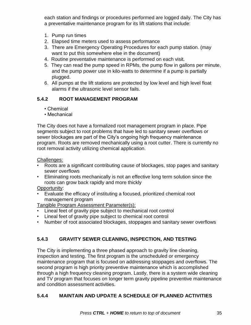
Fig. 19 Auto Dialer 38
Fig. 20 SCADA Screen 38
Fig. 21 Historical Population 44
Fig. 22 Example of GIS Sewer map 44
Fig. 23 City Manhole Rehab 45
Fig. 24 Rebuilt/Raised Chimney 46
Fig. 25 Deteriorated Pipe 47
Fig. 26 Wellhead Protection Map 48
Fig. 27 Leak Detection Visual 49
Fig. 28 Ground Microphone 49
Fig. 29 Gas line in storm sewer 49
Fig. 30 Sanitary Sewer Map 53
Fig. 31 Sewer Service Card 54
Fig. 32 TV Truck 54
Fig. 33 Shirland Avenue pumps 57
Chart 1 Relevant Staff 21
Chart 2 Lift Station Flow Schematic 41
Chart 3 Historical Flow 42
Chart 4 Flow by Month 43
Chart 5 Record Keeping Activities 56
Chart 6 Northwest KW / Hr usage 58
Chart 7 Shirland KW / Hr usage 58
Chart 8 Emergency Call-outs 59
Chart 9 Influent Flow vs Water Levels 59

Press CTRL + HOME to return to top of document 8
PART 1 BACKGROUND
1.1 HISTORY: The first sewers built in Beloit were installed in about the year 1898 and were almost exclusively made out of vitrified clay pipe. Those sewers did not flow to a treatment plant but discharged to ditches, the Rock River, or Turtle Creek. Then after the 1920s, much of the sewer pipe was made out of concrete pipe and that continued up to the 1970s when ABS truss pipe was introduced. Truss pipe was short lived however and most sewer pipe is now PVC plastic pipe. The first wastewater treatment plant was built in the 1950s just south of where the Northwest Lift Station is located today on Water Street. That plant was modified at least three times before the City decided in the 1980s to dismantle the existing plant and construct a new one at the forty-acre site at 555 Willowbrook where it is today. That decision required that 100 percent of the sewage generated by the City would have to be pumped to the new plant about 2.5 miles to the East of the existing plant and an existing interceptor sewer would need to be re-purposed as the effluent pipe to carry the cleaned wastewater back to the Rock River discharging just South of the Shirland Avenue Bridge. 1.2 INFILTRATION: The Beloit sewer system has been plagued with excessive clear water infiltration and inflow (I&I) from the beginning as is seen in the following clip from the Beloit Daily News.
Much of the sewer system in the central business district and along the flood plain of
Turtle Creek is below the seasonal groundwater table. When the River was high or the
creek was flooding, the flows in the sewers would also be high. When the sewers
discharged to the River this was not a perceived problem. When the treatment plant
was built, the excessive flow would affect the ability of the plant to treat the sewage and
would often flood the plant causing emergency bypassing to the River and violations of
the discharge permit.
1.3 I&I STUDY: Prior to moving the treatment plant to its present location an I&I
study was conducted in 1977 by the Engineering Consulting Company, Jensen and
Johnson, to determine the extent of the I&I in the City. At that time, they estimated that
the average infiltration for Beloit was 3.4 million gallons per day (MGD) and the
maximum inflow was 9.3 MGD. The total annual I&I were estimated to be 1.52 billion

Press CTRL + HOME to return to top of document 9
gallons per year. The maximum day total flow was estimated at 16 MGD. The average
actual wastewater flow per day was 3.3 MGD.
1.4 SSES STUDY: A partial sanitary sewer evaluation study (SSES) was done by
the Engineering Consulting Company, CH2MHILL, that came to the conclusion that it
was not cost effective to rehabilitate the sewers influenced by high groundwater or
river/creek levels. The new wastewater treatment plant would have to be sized large
enough to handle all that clear water I&I. The new treatment plant was designed to
handle a maximum flow of 28 MGD and the lift stations were designed to supply that
maximum flow to the plant.
1.5 SEWER REHABILITATION PERFORMANCE: In 1996, five years after the
plant was on line, the city had a rainstorm event that resulted in the design 28 MGD flow
to the plant. It was determined at that time that he City Water Resources Division would
begin attacking and removing the sources of the I&I. Since then a great deal of sewer
rehabilitation has taken place with good results. Today (37 years after the I&I study) the
average daily flows are about 3.6 MGD and the monthly average flow rarely gets above
5 MGD. In 2013, we had high plant flows due to the river and two creeks flooding all at
the same time. The infiltration exceeded the pumping capacity of the Turtle Creek Lift
Station but there was enough storage capacity in the interceptor to prevent an SSO.
Even with that amount of I&I the total annual flow to the plant was 1.617 billion gallons.
At the apparent present daily dry weather flow of 3.6 MGD the total annual flow would
be 1.314 billion gallons. Subtracting the expected yearly flow of 1.314 billion gallons
from last year’s measured total flow gives a total I&I of 303 million gallons. This is an
80% reduction in I&I from the estimates made in 1977!
1.6 STORM SEWERS AND WATER MAINS: The City of Beloit Water Resources
Division is taking an expanded view of the CMOM program in that the storm sewers and
the water mains are seen as important contributors of I&I and are as important to repair
as the sanitary sewer is.
Storm sewer pollution happens when sanitary sewers leak out and infiltrate into
parallel or deeper leaky storm sewers. Often cities have found they have direct
cross connections installed long ago to act as sanitary relief sewers. Finding
these cross connections should be the number one goal when trying to reduce
I&I. The City of Beloit has found and removed two of these relief sewers in the
last 15 years.
The groundwater in well head protection areas needs to be protected from
leaking sanitary sewers that can pollute the local water supply wells.
Leaking sanitary sewers can result in the development of voids under pavements
and in easement areas that can suddenly collapse under foot or vehicle traffic
causing loss of life and property.
Force mains on remote easements can plug, crack or break and be found to be
leaking for days into the environment and probably into some local streams.
Breaks in a force main in very permeable gravels or Karst bedrock areas can go
undetected for even longer periods since there is no visible pooling of sewage.

Press CTRL + HOME to return to top of document 10
A CMOM program should also include properly maintaining the storm sewer system.
Keeping the storm sewers clean and free of cross bores of gas mains and water
services will minimize the amount of storm water that will migrate to the sanitary sewers.
A poorly maintained storm sewer system may result in plugging that can cause
street ponding for long periods. The ponded water usually finds a sanitary sewer
manhole, a sewer trench, a crossing service, or other path to enter the sanitary
sewer system. The sooner the water is off the roadway the less water is available
that can infiltrate the sewer.
Poorly maintained storm sewers often have unknown cross bores of water and
gas services that quickly snag litter, debris and tree leaves that then cause
backups. Unplugging these backups with conventional sewer nozzles or root
saws can lead to disasters if they are not found first with a sewer camera.
Often sanitary sewer services and water mains are laid through a storm sewer
due to conflicts in grade when they were installed and money to correct the
problem was in short supply. Finding these deliberate cross- bores through
sewer televising and getting them corrected goes a long way to restore full
capacity to the storm sewers and sanitary sewers.
Draining the street quickly lessens the amount of water available for infiltration
and inflow and also lessens the pressure forcing the water through the soil and
into the cracks and open joints in the sewer.
Finding and correcting water main leaks will also minimize clear water infiltration.
Poorly maintained and cracked water systems result in too much lost water migrating
into the soils and sewer trenches that then infiltrates the sanitary and storm sewers.
This leakage often causes voids in the ground and high infiltration rates and soil
transfer into the sanitary and storm sewers. Although it is clean water and soil, it robs
space in the sanitary sewer system from real sewage and it must be pumped and
treated with chemicals just as if it were polluted sewage. An aggressive leak detection
program using the latest acoustic technologies pays off in less water loss for the Water
Utility and lowered infiltration rates for the Sewer Utility. Again, many such water leaks
are never seen at the surface if they can find a leaky sewer through the path of least
resistance.
1.7 GEOLOGY: Having a good understanding of the geology of the area
surrounding the sewer system including the location of the various water tables should
also be integrated into a CMOM program.
Knowing where the sewer system crosses into the ground water can help target
sections of the system for rehabilitation given the chronic nature of the infiltration.
These areas should be attacked first since the I&I problems continue most of the
year.
Where sewers are laid in clayey soils and backfilled with crushed stone or gravel
they form a perfect French drain where any rainwater that can find its way into
the trench can fill the trench to the top. This can lead to very long periods of
infiltration until the entire trench is drained.
Sewers laid in sand and gravel that is often twenty to thirty feet above the
groundwater table encourage roots to attack any minute crack or joint that they
can find to get the water they need to grow. These sewers in sandy soils also
exfiltrate sewage that migrates downward to the water table that can then re-
Press CTRL + HOME to return to top of document 11
enter the system some blocks away where the sewer crosses back into the
groundwater.
Areas where the ground is polluted from leaking petroleum tanks or other
chemicals should be noted and special procedures used when cleaning or
rehabilitating these sewers. Flammable air above the sewage can become very
dangerous to the sewer cleaning crew and others.
1.8 UNIQUE STRUCTURES: Special structures or sewers that result in unusual
practices or problems should be noted in the CMOM program.
In Beloit, the effluent return sewer is laid below the water table and below the
normal river level and of necessity runs in a surcharge condition. This is a 54
inch and 60 inch concrete sewer that exfiltrates effluent into the gravel soils
under Shirland Avenue and Colby Street. This exfiltration then forms a slightly
higher than normal water table forcing water to infiltrate the crossing and parallel
sanitary and storm sewers.
The 48 inch Northwest Interceptor sewer was laid along and lower than Lenegan
Creek in 1973 to eventually service the Town of Beloit when they abandon their
own wastewater treatment plant. That option is very unlikely to occur and hence
this sewer is essentially one long septic tank with solids settlement problems.
This sewer requires heavy cleaning due to the low flows we see now (after the
rehabilitation) and will see into the future.
Beloit treats sewage for Illinois residents and businesses located along the state
line West of Prospect Street and East of McKinley Avenue. Collecting fees for the
maintenance and treatment of their sewage has been and still is a problem. At
this time the EPA is working on a solution to this problem and we are waiting for
direction. A sewer has been designed by South Beloit to intercept all the sewers
west of the Rock River and redirect them south into the South Beloit sewer
system. However, implementing this option will result in the removal of a portion
of a fairly new concrete pavement on Shirland Avenue. Correcting the situation
East of the Rock River will mean installing a small lift station, a force main to the
south, and a small length of sewer. South Beloit may decide to negotiate with
Beloit to essentially take over their system in the near future. That option will
come with many additional problems and opportunities.
Beloit has an unusual sixty inch diameter inverted siphon carrying sewage from
the Northwest side of the City under the Rock River and into the Northwest Lift
Station. Most siphons are multi-barreled to maintain minimum velocities through
various flows so that solids will not be deposited and cause plugging. Given the
low average flows seen in this sewer for many years the velocities are also very
low. A contract was let in 2013 to clean the estimated 50 ton of debris that was
previously seen in the low point of the siphon. The Collection Crew will do their
best to clean this oversized siphon at least twice a year using large nozzles on
the Vactor Sewer cleaning trucks. Eventually the city plans to install twin 18 inch
plastic slip-liners through the siphon and will have a flow control structure at the
North end in the vicinity of manhole 49-02. An automated flushing valve is also
anticipated in the Northwest Lift Station so that perhaps once a week the working
18 inch pipe can be surcharged and then quickly opened to flush any solids
deposition downstream.

Press CTRL + HOME to return to top of document 12
1.9 DEFINITIONS
1.9.1 BOD: Biological Oxygen Demand is a biological test that indicates the strength of sewage using live bacteria and the amount of oxygen used during a five (5) day incubation period. 1.9.2 BMP: Best Management Practices 1.9.3 CMAR: CMAR is an acronym that stands for “Capacity Maintenance Annual Report”. Each year the city must complete a CMAR report to the WDNR under NR 208 Wis. Adm. Code and the city’s WPDES permit. This annual report tracks all sanitary sewer functions from wastewater treatment to sanitary sewers. Much of what is required in the CMOM is already addressed in the Wisconsin CMAR reports. The City is graded on nine (9) areas, they are:
1) Influent flow and loadings, 2) effluent BOD quality, 3) effluent TSS quality, 4) effluent phosphorus quality, 5) bio-solids management, 6) staffing, 7) operator certification, 8) financial management and 9) the sewer collection system.
The latest CMAR report at the time of this writing may be found in Appendix A.
1.9.4 CMOM: CMOM is an acronym that stands for “Capacity, Management, Operations, and Maintenance”. It is a flexible, dynamic EPA designed framework for municipalities and sanitary districts to incorporate widely accepted wastewater industry practices to:
Better manage, operate, and maintain sanitary sewer collection systems
Investigate and correct capacity constrained areas of the collection and treatment systems
Prevent and/or adequately respond to sanitary sewer overflow (SSO) events
Better manage, operate, and maintain the Sanitary Sewers, Storm Sewers, Water Mains, and Streets to address Infiltration and Inflow sources to the sanitary sewer system
The CMOM program is a state requirement by the Wisconsin Department of Natural Resources (WDNR) as mandated by the U.S. Environmental Protection Agency (EPA). 1.9.5 CIPP: This is an acronym for Cured In Place Pipe. Simply stated, a polyester felt tube saturated with resin is turned inside out in the sewer and then heated to cure the resin and form a hard pipe within the existing failed pipe. Services are cut back open by the use of special robots and sewer televising equipment.
1.9.6 CVMIC: This is an acronym for the Cities and Villages Mutual Insurance Company. 1.9.7 Daily flow rate: This means the average daily flow calculated for the month that has the highest total flow during the calendar year.

Press CTRL + HOME to return to top of document 13
1.9.8 Easements: All public sanitary sewers that are not located within a publicly dedicated right of way shall be placed in a public utility and drainage easement, minimum 15 feet wide or as directed by the utilities. 1.9.9 EPAC: Is a software Technology database to manage changing environment of maintenance organizations as they focus on reliability, preventative maintenance and maintenance performance. 1.9.10 Flow rate (or discharge or "Q"): Minimum design pumping rate required to deliver effluent in a timely fashion to a gravity system and flow from a pressurized manifold of low pressure pipe laterals. 1.9.11 Grease interceptor (trap): In plumbing, a receptacle designed to collect and retain grease and fatty substances normally found in kitchen or similar wastes. It is installed in the drainage system between the kitchen or other point of production of the waste and the building sewer. 1.9.12 Industrial wastewater: Wastewater from industrial processes or contaminated with wastewater from industrial processes. 1.9.13 Infiltration: (1) The flow or movement of water through the interstices of pores of soil or other porous medium. (2) Groundwater seeping into a collection system. 1.9.14 Inflow: Direct rain flow, such as rooftop drains, open pick holes, and directly connected storm sewers into a sanitary sewer collection system. 1.9.15 Interference: (Am. #3203) Any discharge which, either alone or together with a discharge from any other source:
1. Disrupts or obstructs any process or operation of the POTW; or 2. Causes the POTW to violate any requirement of its WPDES permit; or 3. Prevents sewage sludge use or disposal; or 4. Causes the POTW to lose sewage treatment efficiency.
1.9.16 Lateral: This is the common name for the private sewer service from the connection at the main sewer to the outside wall of the foundation of a building. 1.9.17 Pretreatment Program: Under the pretreatment regulations (40 CFR 403), POTWs are required to develop and implement local pretreatment programs. Through this program, the POTW is directly responsible for the regulation of certain industrial users discharging to the wastewater treatment system. 1.9.18 Requirement for Inspection Manholes and Clean Outs: All commercial, office, institutional, industrial, and manufacturing buildings shall have an inspection manhole located outside of the building that will allow the City to observe the discharge from the building into the public sanitary sewer system. 1.9.19 Sanitary Sewer: A pipe or conduit that carries wastewater. 1.9.20 Sewer Rehabilitation: As with all engineered systems, the wear and tear on a sewage collection system usually leads to the eventual need for rehabilitation of

Press CTRL + HOME to return to top of document 14
portions of the system. Pipes crack and develop leaks, allowing infiltration. Roots find their way through the tiniest cracks and joints and eventually plug the sewer. Poor compaction of the original trench bedding or sloppy careless installation cause dips in the sewer or collapses. Rehabilitation includes everything from chemical joint sealing to total relays. 1.9.21 SSO: SSO is an acronym that stands for “Sanitary Sewer Overflow”. A sanitary sewer overflow is an unintentional release of sewage from a collection system before it reaches the treatment plant. The sewage can contaminate groundwater threatening drinking water supplies or surface water, causing serious water quality degradation, fish kills and other ecological problems and. What is more of a common disgusting problem is it backs up into basements. Overflows are unhealthy, destructive to public and private property, bad for recreation and tourism, and hard on sanitary sewer and drinking water system equipment and increases energy use. Unfortunately, they are a chronic and growing problem in many parts of the country. Major contributions for a SSO are excessive grease, failing infrastructure, roots, road construction debris and illegal discharges. 1.9.22 WPDES Permit: Wisconsin Pollutant Discharge Elimination System, Publicly owned wastewater treatment plants which have a design flow of 1.0 million gallons per day or greater are considered majors, which applies to 88 of the municipal wastewater treatment plants in Wisconsin. See Appendix U.

Press CTRL + HOME to return to top of document 15
PART 2 CMOM PROGRAM GOALS
2.1 GENERAL PROGRAM GOALS
Goals are the first and one of the eight elements of a Capacity, Management, Operation, & Maintenance (CMOM) Program. Program goals help determine the course of action needed to set a CMOM program in motion and then keep it on track. Goals define the purpose and desired result s of the CMOM program. Goals may reflect performance, safety, customer service, resource use, compliance, and other considerations. The City has the following items in place to ensure that the general goals of the CMOM are met:
a. Personnel with position job descriptions appropriate for the CMOM program b. Written internal communication and documentation procedures c. Public information and education program d. Monitor program implementation and measure its effectiveness.
Goals provide direction for the collection system work activities, focusing our time and
money. Collection system goals can be investigative, rehabilitative, operational,
construction-related, budgetary or legal. Goals should be specific, realistic and
achievable. Goals should be those that direct resources to accomplish collection system
tasks or have an outcome in mind. Results should be measureable, such as the task of
cleaning a certain percentage of our system a year or outcome of reducing basement
backups.
2.2 SPECIFIC PROGRAM GOALS
The City has established the following specific goals for itself as part of the CMOM program:
1. Minimize collection system Infiltration and Inflow of clear water. 2. Maximize and maintain collection system design capacity. 3. Minimize structural degradation of the collection and treatment systems 4. Minimize Sanitary Sewer Overflows (SSOs) into homes and to the surface waters
of the State of Wisconsin 5. Maximize the public’s knowledge of the CMOM goals including prohibited
discharges of sump pumps, objects, fats, oils, grease, and pharmaceuticals 6. Quickly identify, locate and repair water main breaks that can cause I&I and
structural failure of the Streets, Sanitary Sewers and Storm Sewers. 7. Quickly identify, locate, clean and repair Storm Sewer plugs or collapses. These
plugs can cause structural failure of Streets, Water Mains and Sanitary Sewers as well as cause street flooding that in turn causes I&I to the sanitary sewer.
8. Minimize conditions causing typical sewer gas production that can cause loss of life and structural microbial corrosion of concrete manholes, pipes and manhole castings.
9. Continuously monitor flows to the three largest lift stations and the treatment plant

Press CTRL + HOME to return to top of document 16
10. Televise 100 percent of the public Sanitary and Storm sewer systems and then again on a routine and on as needed basis.
11. Continuously update and correct data in the City’s GIS mapping programs. 12. Maximize access to the Collection System structures located on easements. 13. Rehabilitate the collection systems based on a defect severity and failure cost
basis.
2.3 INVESTIGATIVE GOALS
2.3.1 TELEVISING:
The City of Beloit has been striving to televise sewers predating the use of PVC
piping or prior to the late 1970s. Sewers built after that have few problems and are
not deemed a high priority for televising. This goal has largely been accomplished
over the last 20 years and the pace of contracted televising has plateaued with two
small interceptor TV contracts in the last two years. Those TV reports with VHS and
DVD format video have been collected and are available at the Water Resources
Division TV studio at 2400 Springbrook Court. However, many of these reports
predate both pan and tilt TV cameras and any standardized (NASSCO) report
format. Generally, in the past about five (5) percent of the system was targeted for
televising each year. One videotape was lost when loaned out to a contractor, so
that video will be one of the first to be re-televised by city forces using our new TV
truck and using our standardized report format. The goal is that the Collections crew
will continue to televise the sewers mostly on an as needed basis and will continue
televising those later model sewers until the entire system is televised. Then we will
start over on a twenty year return cycle. Eventually, the sewer video and the reports
will be attached to the GIS map. Trouble areas will also be televised on a more
frequent basis.
2.3.2 SMOKE TESTING:
The City of Beloit Collections crew has been trained in the art of smoke testing but
has done very little. Based on the lack of flooding history in Beloit, the City does not
have a large inflow problem. The entire low lying Rock River and Turtle Creek flood
plain areas were smoke tested in the late 1980s and some rehabilitation to eliminate
inflow sources was done at that time. Smoke testing will be done on an as needed
basis in the future with the existing smoke testing equipment located at the Water
Resources Division. The smoke testing goal is to smoke test problem areas of
the system when problems occur. Complete system smoke testing may be
advisable but we have given this goal a lower importance than the others listed here.
Figure 1: Defects identified by the smoke
testing program will be attached to the GIS
map until they are corrected.
Press CTRL + HOME to return to top of document 17
2.3.3 FLOW AND POWER MONITORING:
Beloit is a little unusual in that 100 percent of the sewage that reaches the treatment
plant is pumped through a series of lift stations. The larger lift stations have modern
SCADA that allows us to continuously track plant flow, flow from each lift station,
pump RPM, and power usage. These flows are reviewed by the collection system
engineer about three times a week as well as after significant rains, snow melts, and
rises in river/creek levels. The City has two flow meters and a rain gauge for use if
and when a smaller drainage basin study is needed. However, training on these out
dated machines has not been kept up due to personnel changes. Flow monitoring
has been done by contracted Engineering Consultants on the west side of town to
prioritize sewer rehabilitation efforts. The goal is to continue flow monitoring to
be aware of any increases in flow and to document how effective the
continued rehabilitation of the sewer system is. Small basin flow monitoring will
be contracted to Engineering Companies on a case by case basis.
2.3.4 MANHOLE INSPECTIONS:
One of the goals of the City of Beloit is to inspect every manhole in the City
and build inspection reports that can be attached to the GIS system map.
Some preliminary inspection reports have been used and about 200 reports
catalogued. The goal is to get and use an electronic standard inspection form and
import those inspections into a database. This endeavor can be expensive if done by
consultants but given all the duties demanded of the Collections crew this may be
the only practical way to get the goal met. During routine cleaning the Collections
crew visually inspects every manhole they open and they have been instructed to
note on their cleaning reports any that need rehabilitation or further cleaning. These
notes and the pre-paving manhole inspections done by the Collections engineer
have been used for prioritizing sewer rehabilitation in the past. A copy of the
Inspector’s Daily Sheet is found in Appendix B.
2.3.5 DYE WATER CROSS CONNECTION INSPECTIONS:
Usually, dye water testing is done to see where storm water in storm sewers
manages to get into the sanitary sewers. To date we have not done any dye water
testing of this sort. We do however, use dye to trace flushed water from homes and
businesses into the sewer to identify active and abandoned services ahead of CIPP
lining of the sewers. Only active services are re-opened and the newly lined sewer
will not have extra useless holes in the pipe that can allow groundwater to enter. The
goal is to continue dye testing to minimize service reinstatements and to
update the GIS maps with the actual locations of active services. The service
cards in the plumbing inspector’s office should also be updated with this new
information.
2.3.6 LOCATE, RAISE, AND INSPECT MANHOLES:
Many manholes in Beloit have been buried under asphalt, concrete, and soil in
easement areas. As a major tenant of a good CMOM program, showing the DNR
Press CTRL + HOME to return to top of document 18
that we can find, inspect, and maintain all of our manholes is very important. Over
the last 15 years more than 170 manholes have been located, raised and have had
new covers installed. There are 30 manholes still buried or with very poor access
that as we gain access to them we will be raising and inspecting them. The goal is
to have all manholes in the City of Beloit accessible and easy to inspect by
2016.
2.3.7 INSPECT, CLEAN, AND REHABILITATE STORM SEWERS
Storm sewers that are plugged or are flow restricted cause streets to flood which
often submerges the sanitary sewer castings causing a high amount of inflow
through the lids and through the chimney sections. Therefore, the goal of keeping
the storm sewer system fully operational and structurally sound should also
be an important part of any CMOM program goals.
2.4 REHABILITATION GOALS:
2.4.1 SEWER REHABILITATION
About 30 percent of the sewer system is comprised of Portland cement concrete
pipes and about 35 percent is vitrified clay pipes (VCP) that have been installed
since the late 1800s. Due to the historically high groundwater infiltration seen in
certain parts of the city and the expensive fact that 100 percent of the sewage must
be pumped to the treatment plant, attacking the infiltration problem has been the
primary goal in the past. Sewer lining projects since 1996 have greatly reduced the
infiltration problem and many leaks have now reached the point of not being cost
effective to pursue. Due to the poor joint materials used in the past, roots and
infiltration are big problems in both types of pipes. However, concrete also has a
sewer gas corrosion problem that weakens it structurally and it eventually even
becomes porous allowing both infiltration of groundwater and roots to penetrate the
walls of the pipe. The City of Beloit has developed a “warrants” spreadsheet to aid in
the prioritization for rehab of those sewers under the paving projects and those
brought to our attention through TV work or by our Collections crew. Budgets for
doing sewer repair vary from year to year depending on other priorities so no defined
goal of a particular footage of lining can be given. Our general rehabilitation goals
are;
A. Repair or CIPP lining of concrete pipes under high traffic streets, unusually deep sewers, or streets that have already been recently paved will be the next primary goal.
B. Point repairs or CIPP short-liners (5’ to 25’) will also be installed where the rest of the pipe in any particular manhole to manhole section is otherwise in good condition.
C. Chemical sealing of the service connections will be done where groundwater infiltration is a problem. Re-sealing service connections on CIPP lined pipe every five years is recommended. The option of chemically sealing the service from the main to the property line should be evaluated.
D. VCP and other pipes will be relayed or CIPP lined as needed

Press CTRL + HOME to return to top of document 19
2.4.2 MANHOLE REHABILITATION
Figure 2:
Manhole
Rehabilitation
There are about 3,528 active manholes in Beloit as of this writing and many have
already been rehabilitated. Most of the deterioration that we have seen is either in
the top two feet of the manhole or the bottom two feet. Manhole castings and the
supporting adjusting rings or “chimney” below them are major sources of storm
water inflow to the sanitary sewer system. The Collections Crew, as one of their
many duties, does manhole rehabilitation every summer and they usually get
between 50 and 100 manholes rehabilitated every year. The crew has a dedicated
18 foot rehab trailer that has a 100 gallon water tank, cement mixer, power washer,
air compressor, multiple cement storage bins, confined space and other equipment
storage, and a large generator is mounted on the one ton truck that is dedicated to
hauling the trailer.
The Water Resources Division has a line item in the budget for sewer system
rehabilitation that is used to fund CIPP sewer lining, manhole rehabilitation, and
miscellaneous sewer repairs that develop through the year. A maintenance contract
for Trenchless Sewer Rehabilitation (CIPP lining) and a maintenance contract for
open trench Water and Sewer Maintenance are let early every year. Manhole
rehabilitation, replacement, and removal are also part of this program that is
designed and managed by the Collection System Engineer. We do as much work as
we can fit in the timeframe of the construction season and within the budgeted funds
for this work. At this writing the goal was to annually have 70 manholes
rehabilitated by City forces and an equal or larger amount done using the
maintenance contract Contractor. Another goal is to reduce the number of
redundant manholes that are no longer needed. Over 160 have been removed,
lined through, or filled with sand slurry in the past 15 years.
A copy of the Manhole Location, Access and Status inventory list can be found in
Appendix C and Appendix Q.
2.4.3 EASEMENT ACCESS TO MANHOLES
Castings on easement manholes along water ways and through wooded areas have
become attractive nuisances for children who like to remove the lids and in some

Press CTRL + HOME to return to top of document 20
cases the entire casting and then proceed to throw everything they can get their
hands on into the manhole. Beloit has for years been replacing these castings with
the type that are bolted to the cone and the lid is bolted to the frame. Where these
manholes are close to a creek we also have raised them above the high water levels
and installed the
synthetic rubber seals to
help prevent leakage
through the chimney
area. Also seen as a
major requirement for a
comprehensive CMOM
program is the clearing
and maintaining of
easements where
sewers are located. It is
also a goal of Beloit’s
CMOM program to
maintain good access
to all manholes on easements.
Figure 3: Manhole Rehabilitation and sealing
PART 3 ORGANIZATION AND MANAGEMENT
3.1 Organization The Water Resources Division (WRD) employees thirty-two (32) full time employees. It also pays a portion of other employee salaries that assist the department in many ways including but not limited to engineering and billing. The city has eight (8) maintenance staff in which two are Instrument Technicians, three (3) full time plant operators, five (5) Environmental/lab technicians, four (4) collection crew operators, four (4) water utility technicians, two clerical support staff and four (4) supervisors and the Water Resources Director. Current job descriptions may be found on the city’s website.
3.1.1 Staffing Responsibilities for managing and implementing CMOM program activities need to be clearly defined, documented, and communicated. Job descriptions help ensure that all employees know specific responsibilities and individuals have proper credentials. Determination of staff requirements for a collection system requires a working knowledge of the system and consideration of key variables. Key job descriptions may be found in Appendix D.

Press CTRL + HOME to return to top of document 21
3.1.2 Organization Chart
Chart 1: Organizational Chart of relevant
staff
(Not shown on the above Org. chart is the plumbing inspector who works out of the
Community Development Department at City Hall)
3.1.3 Funding (Water Resources Division Funding)
Each year the city completes a comprehensive annual financial report (CAFR) on the utility. The City of Beloit’s sanitary sewer system is funded by a utility fee based on potable water consumption. The utility fee provides a dedicated source of funds for the operation, maintenance, rehabilitation, and improvement of the City’s sanitary sewer system and also the treatment facility. Because the sanitary sewer utility fee is a user fee and not a tax, all property owners are required to pay for the services provided by the City’s sanitary sewer system. This includes non-profit entities such as churches, schools and institutions, as well as properties owned by the City of Beloit, the State of Wisconsin, as well as the federal government. The above utility fees do not include funding for remedial work on the private services from the sewer main to the homes or businesses. By City of Beloit ordinance, that funding is the
Collection Supervisor Environ. Coord. WW Supervisor Water Supervisor Engineer
Equipment Operators Environ. Specs. WW Operators Water Operator Seasonal
Engineer Office Coordinator Maintenance Techs Equipment Ops.
GIS Technician I&C Tech Office Coordinator
Seasonals Environ. Tech. Seasonals

Press CTRL + HOME to return to top of document 22
responsibility of the private property owner. The City in the past several years has had a Capital Improvement Program (CIP) budget of $717,000 for sewers. In 2014 that will be temporarily cut back due to a new phosphorus rule imposed on the City by the State. However, money may be shifted from the CIP budget to the Operation and Maintenance (O&M) budget totaling $563,000 per year. The City keeps approximately $2,731,399 in a DNR equipment replacement fund. A rate study has been budgeted for 2016. Storm sewers and water mains in Beloit are considered infrastructure that can adversely affect the structural condition of the sanitary sewer as well as cause major sources of infiltration and inflow. Hence, the CMOM program will address these utilities as integral to a properly managed CMOM program. The Storm Sewer System is funded based on impervious areas and has an annual budget of $945,000. The Water Main System is funded based on actual metered water use and has an annual budget of about $6,171,600. The City’s plant and sewer assets may be found in Appendix E. On the 2012 CMAR the city received a Grade = A for financial management.
3.1.4 Safety Programs The City is committed to providing a safe and hazard free work place for all employees. At the same time, it is expected that employees shall, as a condition of continued employment, abide by these established standards. These rules are intended to specify the general standards by which employees shall perform their jobs. However, these rules are not exhaustive and individual department rules may apply. Violation of safety rules or standards will result in disciplinary action. Recommendations or suggestions regarding the addition or modification of these safety rules should be made to your supervisor. 3.1.5 Employee Responsibility Each employee is responsible for performing their job with every possible regard for their own safety and for the rights and safety of others and for compliance with all applicable Federal, State and Local safety standards that apply to the performance of their job. All employees, regardless of position, are, as a condition of employment, required to obey all safety rules and general safe work practices that are set forth by these rules and other practices as directed. These general rules are intended to be in conjunction with specific department rules. These rules shall be strictly enforced. 3.1.6 Personnel Protective Equipment (PPE) and Training In order to comply with the WI Dept. of Commerce (COMM 32) and the Federal OSHA Standard (29 CFR 1910.132) the following written program has been established for the city of Beloit, WI. The purpose of the program is to ensure the safety of all employees whenever they may be exposed to a hazard that could cause bodily injury through hazardous processes, environments, chemical hazards, radiological hazards, or mechanical irritants through absorption, inhalation, or physical contact. The program is meant to establish procedures for the selection,

Press CTRL + HOME to return to top of document 23
training, storage, cleaning and use of PPE. The WRD also provide numerous other training opportunities that may found in the training chart in Appendix F.
See Appendix G for Work zone Safety and a copy of the Confined Space Permit.
3.2 MANAGEMENT
3.2.1 General:
City of Beloit’s CMOM program is supported by a strong commitment in both the
budget and personnel to ensure that the water, sanitary and storm water sewer
systems are properly maintained and operated to protect public health and the
environment.
The City has an on-call service 24/7 to deal
with the utility issues. The Collection staff,
Environmental staff, Water Staff, Operations
staff and Engineering staff work closely
together to discuss issues and procedures
needed to cover issues and emergencies
such as back-ups, sewage overflows, illegal
discharges and everyday operational and
maintenance activities.
3.2.2 Public Education Figure 4: PW Foxx as the
Public Works mascot
The City’s Department of Public Works has a dedicated Public Education Committee
who communicate the benefits of the CMOM program along with many other issues
to the public during several events throughout the year. This includes brochures,
DPW week, informational meetings, website and person-to –person contact. The city
also has a mascot named P.W. Foxx who attends many community functions while
handing out public education materials. The City fully participates in Public Works
Week to take the opportunity to show the public what is involved in keeping the
infrastructure and plant structures in proper working order.
Figure 5: Pipe full of grease Figure 6: Page from the kids activity book

Press CTRL + HOME to return to top of document 24
Don’t monkey around. Place your cooled grease in the garbage not down the drain
3.2.3 Best Management Practices (BMPs)
BMP’s are used to prevent the discharge of harmful items into the sewer system to mitigate back-ups from occurring. To reduce our chances of a sewer back-up and to minimize damage if one occurs, the following recommendations are made to the public.:
To our customers:
Do not flush diapers, paper towels, wipes, or plastic products into the sewer system.
Minimize use of your garbage disposal. Disconnect sump pumps from the sewer line (such connections are illegal and
may cause sewage to backup into the home as well as stealing capacity from the sewer). This also results in high costs to pump and treat the clear water.
Elevate your furniture in below-ground levels if basement fixtures are present to minimize damages.
Do not plant trees and shrubs over your sewer lateral. The roots of trees seek out the joints of the sanitary sewer and eventually clog the pipe.
An increasingly common cause of sewage overflows and basement backups is sewer pipes blocked by grease. Grease is often washed into the sewage system through the kitchen sink, and it sticks to the sides of pipes inside your house, in your building sewer, and in the sewer main in the street. Grease also gets into the sewer from poorly maintained grease traps in restaurants and other businesses. Over time, it can build up and block the whole pipe. If this happens in your home or building sewer, it may involve an expensive repair bill. If it happens in the street, it may result in all the sewage from the neighborhood pouring into your basement. Here are a couple helpful items to consider to prevent grease problems:
Never pour grease or oil down sink drains or into toilets. Keep a waste grease and oil container near the stove, and pour waste grease
into it. Scrape grease and food scraps from trays, plates, pots, pans, utensils, and grills
and cooking surfaces into a can or the trash for disposal or recycling. Do not put grease down garbage disposals. Put strainers in sink drains to catch food scraps and other solids, and empty the
strainers into the trash for disposal.
To our Street Construction Contractors;
The bottom of all storm and sanitary manholes within the construction limits must be protected from falling debris, gravel, asphalt, concrete and other substances not allowed in the sewer.
Before final payment, all manholes will be inspected for such debris or damage and it will become the responsibility of the Contractor to properly remove it.
Press CTRL + HOME to return to top of document 25
If the Contractor fails to remove the debris in a timely manner then the City MAY remove it and will deduct the costs from the Contractor’s payments.
All too often, if the Contractor is not careful, the “chimney” or riser section of the manhole just below the casting will be damaged. The Contractor will also be responsible for any damage to this area of the manhole and cost to repair will be deducted from final payment.
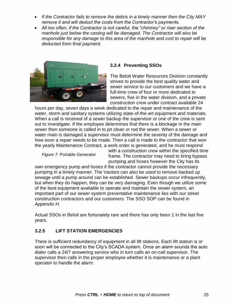
3.2.4 Preventing SSOs
The Beloit Water Resources Division constantly strives to provide the best quality water and sewer service to our customers and we have a full-time crew of four or more dedicated to sewers, five in the water division, and a private construction crew under contract available 24
hours per day, seven days a week dedicated to the repair and maintenance of the water, storm and sanitary systems utilizing state-of-the-art equipment and materials. When a call is received of a sewer backup the supervisor or one of the crew is sent out to investigate. If the employee determines that there is a blockage in the main sewer then someone is called in to jet clean or rod the sewer. When a sewer or water main is damaged a supervisor must determine the severity of the damage and how soon a repair needs to be made. Then a call is made to the contractor that won the yearly Maintenance Contract, a work order is generated, and he must respond
with a construction crew within the specified time frame. The contractor may need to bring bypass pumping and hoses however the City has its
own emergency pump and hoses if the contractor cannot provide the necessary pumping in a timely manner. The Vactors can also be used to remove backed up sewage until a pump around can be established. Sewer backups occur infrequently, but when they do happen, they can be very damaging. Even though we utilize some of the best equipment available to operate and maintain the sewer system, an important part of our sewer system preventative maintenance lies with our street construction contractors and our customers. The SSO SOP can be found in Appendix H.
Actual SSOs in Beloit are fortunately rare and there has only been 1 in the last five years. 3.2.5 LIFT STATION EMERGENCIES There is sufficient redundancy of equipment in all lift stations. Each lift station is or soon will be connected to the City’s SCADA system. Once an alarm sounds the auto dialer calls a 24/7 answering service who in turn calls an on-call supervisor. The supervisor then calls in the proper employee whether it is maintenance or a plant operator to handle the alarm.
Figure 7: Portable Generator

Press CTRL + HOME to return to top of document 26
The City has developed an All Emergency Manual that includes power failures at the lift stations and the treatment plant. This plan includes alternate power source and portable generators.
Figure 8: Thompson Portable Pump The Thompson pump is used in emergency cases where flow may need to be diverted in order to make emergency repairs to prevent SSOs. This pump was sized large enough to handle average daily flows in most of our sewers including our major interceptor sewers. Purchased with this pump was enough 8 inch hose to
bypass a 400 foot length of sewer. This submersible hydraulic pump has been used for many different non-emergency projects over the last three years and is stored at 2400 Springbrook Court along with the hoses and couplings. With a submersible hydraulic pump suction head is not an issue and the pump and discharge piping can easily fit through a manhole casting opening of 19.5 inches.
Figure 9: Potential issues that can affect the sanitary sewer
3.2.6 ENFORCEMENT RESPONSES The City has a strong enforcement response plan stemming from the Industrial Pretreatment Program (IPP). Working closely with other public works departments the Environmental staff investigates possible illegal discharges and issues appropriate enforcement. The City has seven types of enforcement responses. The choice of response depends on the violation severity, duration, impact, and the user’s good faith in taking corrective action. The seven types of enforcement are:
1. Notice of Violation (NOV) (also notice of deficiencies) 2. Administrative Fines (citations, forfeitures) 3. Administrative Orders (AO may be compliance schedules, etc.)

Press CTRL + HOME to return to top of document 27
4. Cease and Desist Orders 5. Civil Litigation 6. Criminal Prosecution 7. Termination of Service
3.2.7 SERVICE AGREEMENTS, MUTUAL AID OR MANAGEMENT
AGREEMENTS
The city has sewer service agreements with the Town of Beloit, the Town of Turtle and the City of South Beloit, IL. For example an excerpt from the agreement with the Town of Beloit is seen below. “The Town shall retain ownership of all Town sanitary sewer mains located within the Town’s 208 area boundary, as well as any extensions outside the boundary required to connect the Town’s sanitary sewer mains to the City’s interceptor(s). The Town shall maintain these sewer lines in full conformance with DNR regulations, including, but not limited to, those regarding inflow and infiltration”.
PART 4 LEGAL AUTHORITY
4.1 SEWER USE ORDINANCE
The city has an extensive sewer use ordinance that may be found in Appendix I. In
order to implement an effective CMOM program, the City must have sufficient legal
authority to authorize implementation activities. The proposed CMOM program
implements five classes of activities that the EPA generally believes are necessary for a
CMOM program:
1. Control of infiltration and connections to inflow sources. 2. Requirement that sewers and connections be properly designed and constructed. 3. Ensure proper installation, testing, and inspection of new and rehabilitated
sewers. 4. Address flows from municipal satellite collection systems. 5. Implement the general and specific prohibitions of the national pretreatment
program (see 40 CFR 403.5). 6. GOING A STEP BEYOND BASIC REQUIREMENTS:
Backwater drain stops. Requirement of backwater drain stops and backwater valves. In existing buildings, all floor drains connected to the sanitary sewer system shall be equipped with, at minimum, a backwater drain stop which fits into the floor drain. In new construction, the building drain shall be equipped with a backwater valve which complies with the State Plumbing Code. Backwater drain stops and backwater valves shall be installed at the owner's expense. "New construction" is any building constructed after January 1, 1995.
4.2 PRETREATMENT OR INDUSTRIAL CONTROL PROGRAM
The City has a full time Environmental staff that implements and enforces the EPA’s mandated pretreatment program. This program establishes uniform requirements to the

Press CTRL + HOME to return to top of document 28
City wastewater collection and treatment system and enables the City to comply with applicable State and Federal laws required by the Clean Water Act, 33 U.S.C. 1251 et. seq. and the General Pretreatment Regulations 40 CFR, Part 403. 4.3 GOING A STEP BEYOND BASIC REQUIREMENTS Permits. In addition to the activities listed above the city has a permit requirement in which all significant industrial and all commercial users are required to be permitted. This allows the city to track all potential types of discharges from the business community. FOG. The city also has an aggressive fats, oil and grease (FOG) program. The Environmental staff inspects commercial grease traps on an as needed or annual basis and works with the Collections Supervisor when domestic source FOG problems are found in the sewer. This program ensures proper operation and oversees the treatment facility and its conveyance system to ensure proper operation and that the conditions of the WPDES discharge permit are met. The Environmental staff issues discharge permits to all significant industrial users (SIUs) and all commercial users on the city’s sanitary sewer system. With the sewer use ordinance (SUO) providing a sound enforcement structure this program ensures that flow capacity is protected and prohibits illegal discharges that may hinder the flow or cause deterioration in the sewers. Annual inspections of grease traps ensure that nonresidential users are properly maintaining grease traps on a regular basis. This program allows for stringent enforcement of violations of the permits or ordinance that may result in SSOs that are considered to be a health hazard. The City has between 700-800 commercial businesses that are permitted at any given time.
4.4 LATERAL MAINTENANCE AND I&I
Sections of the ordinance address issues such as laterals and plumbing requirements.
Both ordinances help address the issues of lateral maintenance and I&I. Below is an
excerpt from the Beloit Municipal Code of Ordinances:
29.04 MANAGEMENT, OPERATION AND CONTROL
(1) RECORDS. (Am. #3082; #3318) All financial records of the POTW shall be kept by
the Finance and Administrative Services Department. All records pertaining to the
operation and management of the POTW shall be kept by the Public Works Director.
(2) LATERALS. (Am. #3043) Laterals shall be installed, maintained and repaired at the
owner's expense. The owner shall protect the lateral from frost, tree roots and
infiltration. If 2 or more buildings share a lateral, each building shall be disconnected
from the other and a separate lateral shall be installed for each building. No user shall
allow any other person to connect to the sewer system through the user's lateral. A user
or the user's plumber shall notify the City of any blockage which is discharged from the
user's lateral into the POTW.
29.04(h) Maintenance of Interceptors Required. (Am. #3203; #3318) Any person who
is required by Ch. 82, Wis. Adm. Code, to install a grease interceptor, oil interceptor or
sand interceptor shall, at all times, maintain the interceptor in proper working order. The

Press CTRL + HOME to return to top of document 29
interceptor shall be readily accessible for cleaning and inspection at all times. No
person may return gray water to an interceptor unless a written variance is granted by
the City. "Gray water" means all liquid contained in a grease interceptor that lies below
the floating grease layer and above the solid grease layer. The owner of a grease
interceptor shall system keep a log describing the cleaning and repairs performed on
the grease interceptor and the dates of such activity. The log shall be kept on site for 3
years.
29.045 RULES AND REGULATIONS
(1) GENERAL. This chapter shall be incorporated into any contract for the use of the
City's sewer system and shall be incorporated into every permit issued for the use of the
City sewer system.
(2) PLUMBING. (Am. #3043) No person shall do any plumbing or pipe fitting work in
connection with the City sewer system without a Wisconsin plumber's license or without
written permission from the City. Plumbers shall provide the City with proof of such
authorization, upon demand. All plumbing and pipe fitting work shall comply with the
State plumbing code. Plumbers shall notify the City whenever any blockage in a user's
lateral is discharged into the POTW. Pipes should always be tapped at or near the top;
more than 6 inches from the joint; and more than 24 inches from other lateral
connections. Laterals shall be connected to the City's sewer by saddles and by coring or
by cutting a "Y" or a "T" into the City sewer. The City must approve all adapters and
couplings used to connect the lateral to the City sewer system. Whenever a lateral is
connected to the City's sanitary sewer system, the lateral shall be inspected and tested
to ensure that the lateral or connection will not contribute to infiltration or inflow. The
ordinance also has specific prohibitions that create protection against pollutants that
would cause obstruction or threaten capacity as seen below.
29.10 DISCHARGE PROHIBITIONS
(1) GENERAL DISCHARGE PROHIBITIONS. (Am. #3318) No user shall discharge any wastewater and/or pollutant that will pass through the POTW or interfere with the operation or performance of the POTW, alone or in combination with the effluent discharges of others. These general prohibitions apply to all users, including those who are subject to national categorical pretreatment standards or any other national, State or local pretreatment requirements.
(2) SPECIFIC DISCHARGE PROHIBITIONS. No user shall discharge any of the following into the POTW:
(f) Solid or viscous substances which may obstruct the flow in a sewer or otherwise interfere with the operation of the wastewater treatment facilities such as, but not limited to: grease, garbage with particles greater than ½ inch in any dimension…..
(q) Any unpolluted water including, but not limited to, noncontact cooling water, stormwater or groundwater unless otherwise approved by the City. (Am. #3318)
(r) Any wastewater containing fat, wax, grease or oil, in excess of 300 mg/l, whether emulsified or not, which may solidify or cause interference or become viscous at

Press CTRL + HOME to return to top of document 30
temperatures between 32°F (0°C) and 150°F (65.6°C); or any wastewater containing oil and grease concentration of mineral origin or greater than 25 mg/l whether emulsified or not. (Am. #3043; #3203)
4.5 ENFORCEMENT
The City’s Environmental staff dedicates an employee to perform (at a minimum) annual inspections at facilities that have food service operations. The staff works closely with the Collection Crew who through closed circuit TV identifies problem areas, illegal discharges, and clear water connections. Grease traps are inspected at least annually. BMPs are discussed with the customer who must maintain grease traps on a regular basis and keep a cleaning log. Those that violate the grease program are subject to notices of violation, fines (citations) or orders to install exterior grease straps. The Collection System Supervisor also can issue citations to citizens or contractors for violations of the ordinance.
PART 5 MAINTENANCE AND ACTIVITIES
5.1 EQUIPMENT AND TOOLS The city owns and operates two Vactor units to maintain both sanitary and storm sewers. The two Vactor units along with supplemental equipment such as barricades, sewer plugs, etc. needed in the collection system is located at 2400 Springbrook at the Water Utility/Engineering building. Equipment for the plant and lift stations is located at the wastewater treatment plant located at 555 Willowbrook Road. The utility does have portable generators to use in the case of emergency including but not limited to power failures at the lift stations and sewer bypass for maintenance reasons.
Figure 10: Welding / Maintenance Figure 11: Maintenance Shop A well- equipped maintenance shop is located in the north east side of the headworks building and there is one outside cold storage building where mowers, pumps and other supplies are kept.
The City provides each member of the maintenance staff an annual “tool allowance” to purchase tools such as wrenches and sockets for everyday use. The City also

Press CTRL + HOME to return to top of document 31
purchases “specialty tools” that remain in the maintenance shop for use by all the maintenance staff. Lift Station Maintenance Truck equipped with: 4 Emergency Generators
Crane for lifting pumps * 80 kW
Small generator * 150 kW
Various tools for pump maintenance * 175 kW
Appropriate safety equipment * 300 kW
Small tool inventory is adequate but there is no inventory control in place. The situation is the same for spare parts and replacement equipment, that is, adequate supplies and spare parts are available but there is no inventory control.
Figure 12: The ‘Rover’ Sewer Camera Figure 13: Two Vactor units on duty
5.2 MEASURES AND ACTIVITIES A list of the steps used with the GIS to evaluate the wastewater collection system includes: (1) select a base map, (2) define sewer system service areas, (3) estimate wastewater flows, (4) define sewer system loads and capacities, (5) evaluate sewer system conditions, and (6) define collection system projects. Measures, activities and program requirements need to be tailored to the size, complexity and specific features of the collection system. The proposed CMOM program specifically identifies nine general classes of measures and activities that EPA believes are generally appropriate and applicable for most municipal sanitary sewer collection system programs.
1. Goals 6. Overflow emergency plan 2. Organization 7. Capacity assurance 3. Legal authority 8. Annual self-audit 4. Maintenance activities 9. Monitoring, Measuring, Updates 5. Design and performance measures
5.3 MAINTENANCE FACILITIES AND EQUIPMENT The City provides adequate maintenance facilities and equipment. Maintenance facilities are locations where equipment, materials and personnel are dispatched and where operations records are kept. In 2003 the City of Beloit acquired the water system infrastructure from Alliant Energy and in 2003 also purchased the present Utilities and

Press CTRL + HOME to return to top of document 32
Engineering Facility (built in 1982) from Alliant Energy. The building is adequate to house the Water Department, the Sewer Department, the Engineering Division, the Environmental Department, the Director of Public Works and all the utility vehicles under one roof. The building has record storage areas and a large inventory of water department materials as well as a dedicated meter testing and rehabilitation area. An outside paved and fenced storage area is also adjacent to the building that has stockpiles of manhole castings, water hydrants, manhole sections, manhole adjusting rings, pipes, and other materials. The property is large enough to expand to the East, South and West if necessary. The POTW alarm list maybe found in Appendix J. Basic proceedures for alarm testing can be found in Appendix T.
Figure 14: The Waste Water Treatment Plant was built in 1992 on about 40 acres of land and has plenty of room for the designed expansion in the future. The Administration Building houses the Laboratory and staff, the Treatment Plant Supervisor, Maintenance Staff, and Plant Operators.
Figure 15: Treatment plant emergency generator
The City also owns a building in neighboring Clinton, WI that houses most of our Bio-Solids hauling and spreading equipment. This building is approximately 7200 square feet in size. The City now has the Bio-Solids options of 180 day storage, 4% solids field injection, 15% solids field spreading, or 15% solids hauled to landfill. The Utilities and Engineering Building is linked to the WWTP, City Hall and other buildings by fiber optic and radio antenna for communications, SCADA, GIS, Munis, City Works, and other computer needs. The equipment mostly associated with a CMOM program that the City owns and operates:

Press CTRL + HOME to return to top of document 33
Two Vactor combination trucks
A rodding machine
An eighteen foot enclosed manhole rehabilitation trailer
A 16 foot custom built RST Closed Circuit Televising van with “Possum” software
A Thompson Submersible Hydraulic pump (1100 GPM @ 40’ head) for emergency bypassing
Many portable generator units for remote lift stations and water wells
A 1.5 megawatt back-up diesel generator permanently installed at the WWTP (above)
Figure 16: TV Truck Figure 17: Sewer Rehab Trailer
In CMOM planning, the utility selects performance goal targets, and designs CMOM
activities to meet the goals. Information collection and management practices are used
to track how well each CMOM activity is meeting the performance goals, and whether
overall system efficiency is improving.
(1) General Standards- As a permittee, the City is required to:
(a) Properly manage, operate, and maintain at all times, all parts of the collection system that you own or have control over.
(b) Provide adequate capacity to convey base flows and peak flows for all parts of the collection system.
(c) Take all feasible steps to stop, and mitigate the impact of, sanitary sewer overflows in portions of the collection system.
(d) Provide notifications to parties with reasonable potential for exposure to pollutants associated with the overflow event. (i) If an SSO discharges to the waters of the state from your collections system, you
must develop a written summary of your CMOM program, and make it and the audit under section available to any member of the public upon request.
(ii) Develop a chain of communication for reporting SSOs under 122.42(g) from receipt of the complaint or other information to the person responsible for reporting to the WPDES authority.
5.4 ROUTINE PREVENTIVE OPERATION AND MAINTENANCE ACTIVITIES
You must provide adequate preventive and routine maintenance including predictive preventive maintenance approaches which use processes, including information

Press CTRL + HOME to return to top of document 34
management systems, to continually review and update maintenance procedures as new problems arise or the status of existing situations change. Again, in order to implement an effective CMOM program, the City must have sufficient
legal authority to authorize implementation activities. The proposed CMOM provision
identifies five classes of activities that EPA generally believes are prevent service
interruptions and system failures which can result in overflows and/or backups. In
addition to preventing service interruptions and system failures, a preventive
maintenance program can protect the capital investment in the collection system.
Preventive maintenance activities should ensure that the permittee:
1.) Routinely inspects the collection systems and addresses defects or other problems.
2.) Investigates complaints and promptly corrects faulty conditions. 3.) Provides maintenance records, an adequate workforce and appropriate
equipment in good working order. 4.) Maintains and updates a schedule of planned activities. 5.) Preventive maintenance activities typically address: a.) Planned, systematic, and scheduled inspections to determine current conditions
and plan for maintenance and repairs. b.) Planned, systematic, and scheduled cleaning and repairs of the system based on
past history. c.) Proper sealing and/or maintenance of manholes. d.) Regular repair of deteriorating sewer lines. e.) Remediation of poor construction f.) A program to ensure that new sewers and connections are properly designed
inspected and constructed without new connections of infiltration or inflow g.) A program to oversee lateral and private collection system installations that tie in
to public wastewater collection systems. h.) A program to eliminate existing illegal inflow sources and a strategy for informing
and educating the public about such sources.
5.4.1 CLEANING AND MAINTENANCE
1. The cleaning and maintenance of the sanitary sewer will be developed
each year by basin. All sewer lines between 6” – 24”" in diameter will be cleaned
every two (2) years. Sewer lines over 24” will be cleaned every five (5) years.
Problem areas will be checked and cleaned every 3-6 months depending on
severity.
The sewer cleaning SOP may be found in Appendix K.
2. All cleaning, televising, root control and other maintenance of sewers
shall be logged and placed in the GIS program. Sanitary sewer backups shall be
tracked in the GIS mapping program. The Environmental staff will be notified of
any blockages, illegal discharges and any other problems associated with the
sanitary sewers for investigation and enforcement as necessary.
3. There are eleven (11) lift stations within the City. Operational manuals
for all lift stations are available at 555 Willowbrook Road. See Appendix R for
complete manual list. The lift stations are inspected daily by either a plant
operator or maintenance personnel. The operator goes through a checklist for
Press CTRL + HOME to return to top of document 35
each station and findings or procedures performed are logged daily. The City has
a preventative maintenance program for its lift stations that include:
1. Pump run times
2. Elapsed time meters used to assess performance
3. There are Emergency Operating Procedures for each pump station. (may
want to put this somewhere else in the document)
4. Routine preventative maintenance is performed on each visit.
5. They can read the pump speed in RPMs, the pump flow in gallons per minute,
and the pump power use in kilo-watts to determine if a pump is partially
plugged.
6. All pumps at the lift stations are protected by low level and high level float
alarms if the ultrasonic level sensor fails.
5.4.2 ROOT MANAGEMENT PROGRAM
• Chemical • Mechanical
The City does not have a formalized root management program in place. Pipe segments subject to root problems that have led to sanitary sewer overflows or sewer blockages are part of the City’s ongoing high frequency maintenance program. Roots are removed mechanically using a root cutter. There is currently no root removal activity utilizing chemical application. Challenges: • Roots are a significant contributing cause of blockages, stop pages and sanitary
sewer overflows • Eliminating roots mechanically is not an effective long term solution since the
roots can grow back rapidly and more thickly Opportunity: • Evaluate the efficacy of instituting a focused, prioritized chemical root
management program Tangible Program Assessment Parameter(s): • Lineal feet of gravity pipe subject to mechanical root control • Lineal feet of gravity pipe subject to chemical root control • Number of root associated blockages, stoppages and sanitary sewer overflows 5.4.3 GRAVITY SEWER CLEANING, INSPECTION, AND TESTING The City is implementing a three phased approach to gravity line cleaning, inspection and testing. The first program is the unscheduled or emergency maintenance program that is focused on addressing stoppages and overflows. The second program is high priority preventive maintenance which is accomplished through a high frequency cleaning program. Lastly, there is a system wide cleaning and TV program that focuses on longer term gravity pipeline preventive maintenance and condition assessment activities.
5.4.4 MAINTAIN AND UPDATE A SCHEDULE OF PLANNED ACTIVITIES

Press CTRL + HOME to return to top of document 36
Figure 18: Manhole Inspection Report (Appendix L) Preventative Maintenance Activities: a. Planned, systematic, and scheduled inspections to determine current condition
and plan for maintenance and repairs. All crews inspect the infrastructure they are working on and report any work that is needed.
b. Planned, systematic, and scheduled cleaning and repairs of the system based on past history. Many areas in Beloit are on a list of trouble spots that get attention on an accelerated schedule.

Press CTRL + HOME to return to top of document 37
c. Proper sealing and/or maintenance of manholes. The Sewer Crew has been trained on manhole sealing and include these activities when doing manhole rehabilitation.
d. Regular repair of deteriorating sewer lines. Repairs are done mostly by the Annual Maintenance Contractor.
e. A program to oversee lateral and private collection system installations that tie into public wastewater collection systems. The plumbing inspector is in charge of these connections on existing sewers. The Engineering division is responsible for getting service locations and insuring air tight connections are made to new sewers.
f. A program to eliminate existing illegal inflow sources and a strategy for informing and educating the public about such sources. The Collection System Engineer is responsible for video inspection of existing sewers and to locate and schedule rehabilitation of leaky or structurally deficient sewers. Notices are sent to the property owners and renters with their water bills that help educate the public on illegal discharges to the sewer system.
5.5 LIFT STATION MAINTENANCE AND OPERATION
5.5.1 GENERAL: The City has an extensive lift station unscheduled and scheduled preventive maintenance program for its eleven (11) lift stations. High flow stations are typically suction lift while the majority of the smaller, feeder stations are submersible. Each station is flooded suction with wet/dry wells. Lift stations unscheduled and preventive maintenance programs are managed through the EPAC computerized maintenance management program. About half of the stations have been rehabilitated over the last 5 years with an extensive renovation plan contracted in 2013 for each of the major stations. Extra pumps and parts are kept on hand to ensure that lift stations stay operational. 5.5.2 ROUTINE OPERATION: Routine operation of the lift stations is performed by the operations staff. Pump run times, flows, electrical usage and buildings/grounds components are checked daily. Lift stations are pumped down weekly to remove surface grease and debris. At this time, a comprehensive examination of all lift station components takes place. Additionally, each of the wet wells is cleaned with a high pressure flush at least once per year. Nuisance accumulation of grease, solids and debris will warrant more frequent cleaning. Lift station maintenance activities are divided in to three categories: mechanical, electrical and instrumentation. Mechanical maintenance on pumps, valves, checks, piping and other assets are completed in accordance with the manufacture recommendation particular to each piece of equipment and performed by experienced maintenance technicians. Asset preventive maintenance schedules have been integrated into the EPAC and are reviewed on an annual basis. Preventive maintenance work orders are generated by EPAC on a bi-weekly basis and distributed to the crews electronically. Corrective maintenance work orders are also distributed electronically and are discussed amongst plant staff prior to the work being done on a daily basis based on observations during station checks. Consequently, a portion of the preventive maintenance activities originally set up based upon the manufacturers’ requirements have since been modified, as appropriate, to be specific to the individual stations and their operating conditions.
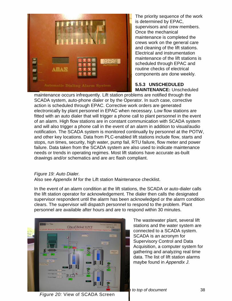
Press CTRL + HOME to return to top of document 38
The priority sequence of the work is determined by EPAC, supervisors and crew members. Once the mechanical maintenance is completed the crews work on the general care and cleaning of the lift stations. Electrical and instrumentation maintenance of the lift stations is scheduled through EPAC and routine checks of electrical components are done weekly. 5.5.3 UNSCHEDULED MAINTENANCE: Unscheduled
maintenance occurs infrequently. Lift station problems are notified through the SCADA system, auto-phone dialer or by the Operator. In such case, corrective action is scheduled through EPAC. Corrective work orders are generated electronically by plant personnel in EPAC when necessary. Low flow stations are fitted with an auto dialer that will trigger a phone call to plant personnel in the event of an alarm. High flow stations are in constant communication with SCADA system and will also trigger a phone call in the event of an alarm in addition to visual/audio notification. The SCADA system is monitored continually by personnel at the POTW, and other key locations. Data from PLC-enabled lift stations include flow, starts and stops, run times, security, high water, pump fail, RTU failure, flow meter and power failure. Data taken from the SCADA system are also used to indicate maintenance needs or trends in operating regimes. Most lift stations have accurate as-built drawings and/or schematics and are arc flash compliant.
Figure 19: Auto Dialer.
Also see Appendix M for the Lift station Maintenance checklist.
In the event of an alarm condition at the lift stations, the SCADA or auto-dialer calls the lift station operator for acknowledgement. The dialer then calls the designated supervisor respondent until the alarm has been acknowledged or the alarm condition clears. The supervisor will dispatch personnel to respond to the problem. Plant personnel are available after hours and are to respond within 30 minutes.
The wastewater plant, several lift stations and the water system are connected to a SCADA system. SCADA is an acronym for Supervisory Control and Data Acquisition, a computer system for gathering and analyzing real time data. The list of lift station alarms maybe found in Appendix J.
Figure 20: View of SCADA Screen

Press CTRL + HOME to return to top of document 39
SCADA alarms are tested several times per week. The maintenance schedules of the lift stations include pumping down the water level of the station below the low level alarm point. Once the low level alarm is engaged, it triggers an alarm that is radio transmitted to the SCADA and the Trouble Auto-Dialer makes an automated call with the conditions of the alarm to the Operator’s lift station cell phone. This procedure verifies the working function of the float alarm mechanism, SCADA system, radio communications and circuit components. Problems are then noted and placed into EPAC so that maintenance will address any issues. Other critical SCADA alarms are tested by either of the two methods: 1) connecting to a laptop to perform diagnostic checks or 2) the alarm condition circuit is bypassed, simulating an alarm which triggers the SCADA. All critical alarms are tested monthly and documented. Challenges:
It is a challenge to get detailed, up to date late station maintenance data entered into EPAC
Grease is a problem both for the lift stations and for the air release valves (ARVs).
Aging pumps and infrastructure that requires more maintenance and routine checks
Opportunities:
Purchase hand held computing devices with drop down menus for the lift station maintenance staff
Tangible Program Assessment Parameter(s):
Number of lift station Preventative Maintenance (PMT)
Lift station backlog
5.5.4 FORCE MAIN MAINTENANCE: The pressure system maintenance
performed by the City includes a valve maintenance and exercise program at the lift
station sites and air release valve maintenance and replacement program. The
system includes approximately 10,800 feet of 24” and 3,300 feet of dual force mains
that run through each of the main lift stations. The structural integrity is maintained
through sacrificial anode cathode protection. There are 15 test stations along the
mains for testing the pipeline, castings and foreign line crossings. There are 2 air
release valves and 3 gate valves for each force main.
The program for maintaining these assets are managed through the EPAC
maintenance management system. The work orders direct maintenance staff with
information that includes valve location and the number of turns required to properly
exercise each valve. Valves are exercised concurrently with the routine lift station
preventive maintenance program.
There is currently a program for maintaining the rights of way or easements where
the force mains are situated outside of street locations. Easements are cleared at
least once and often twice a year.
Challenges:
The integrity of the force mains has been evaluated and needs repairs

Press CTRL + HOME to return to top of document 40
Access and maps with all easements plotted
Opportunity:
A close interval study and a soil resistivity study were completed on the force mains.
An impressed current system was recommended to replace the sacrificial anodes.
Expand force main right of way and easement maintenance program.
Expand the valve maintenance program to include the remainder of the system.
Tangible Program Assessment Parameter(s):
o Number of air release valves inspected, exercised, repaired and replaced
o Number of gate valves inspected, exercised, repaired and replaced
PART 6 SYSTEM DESIGN AND PERFORMACE MEASURES
6.1 SANITARY SEWER SYSTEM DESCRIPTION
The City of Beloit (incorporated in 1856) now has over 173 miles of sewer between
2”and 60” in diameter (some of which are in South Beloit, Illinois) with over 3,528
manholes and over 30,000 feet of force mains. The Government Accounting Standards
Board (GASB) released GASB -34 in June 1999, requiring state and local governments
to report all infrastructure assets, including sewers, in their annual reports and has been
required since June 15, 2003. The Sanitary Sewer system has been numbered,
inventoried and divided into 84 drainage basins for the annual GASB 34 inventory
needs and for past and future I&I studies. All rehabilitation to the sanitary sewer system
is documented on a yearly basis and the inventory GIS maps are updated. The inch-
miles of sewer of each size have also been determined and are also included in the
inventory spreadsheet listed as Appendix C at the back of this document. A map of the
four largest drainage basins leading to Northwest Lift Station, Shirland South lift Station,
Big Shirland Lift Station and Turtle Creek Lift Station is included as Appendix N. The
inventory does not break down the system by pipe type; however, a layer on the GIS
maps does show the pipe types. The pipes are made of clay, concrete, PVC, ABS
Truss, asbestos cement (Transite) and cast iron.
The City operates and maintains 11 lift stations that have the ability to connect to trailer
mounted generators in case there is a loss of power. See chart 2 for the flow schematic
of all lift stations tributary to the treatment plant. All of the city’s sewage is pumped to
the Treatment Plant and then flows through the plant and back to the Rock River by
gravity. Two small lift stations were renovated in 1996 and the city has done a facility
plan to renovate the five largest lift stations hopefully in the next two years. The City of
Beloit has one large single barrel inverted siphon (60”) on the Northwest Interceptor that
dives under the Rock River before entering the Northwest Lift Station. That siphon was
recently cleaned of over 50 tons of debris, dewatered, inspected, and rehabilitated.
There is also the basin 36 three barrel siphon that may be “mothballed” for many years
if some piping changes get made in that basin. The siphon is problematic and is not
necessary since the Hospital Interceptor is just a few feet away and is very underutilized
and needs additional flow

Press CTRL + HOME to return to top of document 41
Average monthly flows to the treatment plant over the past three years have
varied between three and five million gallons per day (MGD). The treatment plant
is designed to hydraulically handle up to 28 MGD and is designed to treat 11.3
MGD.
Chart 2: Lift Station Flow
Schematic

Press CTRL + HOME to return to top of document 42
6.2 PAST REHABILITATION EFFECTIVENESS
The City has been aggressively rehabilitating the sanitary sewer system since1996 and
has had a significant impact in reducing not only the hourly, daily and monthly peaks in
flow but as you can see in chart 3 below, the total annual flow through the wastewater
treatment plant has declined. Since 1989 the city has installed approximately 16.36
miles of cured in place pipe (C.I.P.P) of the polyester felt and polyester resin type
materials. About 124 manholes have been cement mortar lined and hundreds of
manholes have been rehabilitated. About a hundred manholes have been abandoned,
2.3 miles of unused sewer lines eliminated, and hundreds of unused services eliminated
since 1996. Most of the rehabilitation has been focused on the low lying flood plain
areas that have chronic high ground water tables associated with high river and creek
surface levels. Basins one, two, four, fifty, sixty three, sixty four, and seventy nine have
historically contributed to the high infiltration rates.
Chart 3: Historical flow by year in millions of gallons
One can see from the above chart that the sewer rehabilitation done over the last 17 years has dramatically reduced the annual flow to the treatment facility by about 50 to 60 percent. Peak to base flow ratios have also been reduced. However, river and creek flooding still impacts the system far more than most rainfall events. The average monthly flows to the treatment facility from 2009 through 2013 are shown below. Once the repairs are made to the 48 inch Hospital Interceptor future flows should be about where the flows were in 2012.

Press CTRL + HOME to return to top of document 43
Chart 4: Average monthly flow in millions of gallons
The graph above shows the annual monthly flows to the treatment plant for the past five years compared to the 11.3 MGD flow rating. The City experienced flooding conditions in 2013 from March through May. During the flood events, even with some days as high as 20 MGD, the treatment plant met or exceeded all of its permit parameters. All the City’s lift stations and sewers also performed very well with no SSO during this period.
PART 7 CAPACITY ASSURANCE
7.1 OVER CAPACITY PROBLEMS
The efforts of the Water Resources division since 1996 to minimize the I&I in the sewer system have been able to cut the flow to the treatment plant roughly in half. A large portion of the I&I was river related since much of Beloit is built on gravel deposits far above any groundwater table. A large portion of the sewer rehabilitation was focused on the sewers near the Rock River, Lenegan Creek and Turtle Creek. This reduction in flow saves on pumping electrical costs, minimizes wear and tear on plant and lift station rotating equipment as well as minimizing the chemical costs to disinfect the effluent. However, the reduction in flow has some negative effects. The loss of flow causes a reduction in the speed of the sewage in sewers that will cause solids deposition. The solids begin to naturally biologically break down giving off hydrogen sulfide gas as well as methane. This produces a mixture of corrosive and explosive gas that obviously is dangerous to sewer workers but it also corrodes the concrete sewers and manholes. The influent at the plant is nearly septic and is quite odorous but this also helps with the nutrient density for enhancing biological phosphorus removal.

Press CTRL + HOME to return to top of document 44
In 1973 the Northwest Interceptor 60 inch and 48 inch diameter concrete sewer was built out to its terminus at Newark Road. This sewer was designed to receive the flow from the Town Of Beloit wastewater treatment plant if and when they annexed into the City of Beloit. On the East side of the City, what we call the Hospital Interceptor, was a concrete sewer built to service the new Beloit Memorial Hospital and population growth to the northeast. At that time the City of Beloit and the area around Beloit was growing far faster than it has in the following 40 years. Population projections for the area at that time were used to size sewers, however that growth projection was not to come. The following graph illustrates how little growth has occurred in the last 40 years. When the new Wastewater Treatment Plant was built at its present site in 1992 the design engineers had to build lift stations to get the sewage from the existing sewers to the new plant. Unfortunately, the lift stations were built with historical high peak I&I in mind along with the previous population growth projections. They were also built with multiple large pumps with no smaller pumps to run during dry periods when there was very little groundwater infiltration. Today we have three lift stations that are far oversized for the daily flows with only one large pump in each station running very slow and inefficiently. These pumps are getting plugged often and are wasting energy. A lift station facilities plan renovation study was done by the engineering consulting firm ATI Inc. in 2012 that recommended new pumps and other modifications to five lift stations. Due to the reduced flows in these oversized sewers from both I&I reduction and lack of population growth the Collection System crew will need to clean these interceptor sewers on a three to five year cycle. Cleaning large diameter pipes uses large volumes of water and takes crew time away from the more problematic 8 inch diameter sewers. The reduced flows therefore have caused the need for more manpower, water, easement access, and wear on equipment.
Figure 21: Beloit’s Historical Population Figure 22: Example of GIS Sewer Map

Press CTRL + HOME to return to top of document 45
7.2 SEWER SYSTEM UNDER CAPACITY PROBLEM AREAS
At this writing there is only one known flow constricted sewer in the City of Beloit. This sewer is a 15 inch concrete trunk sewer that drains basins 70, 71, 72, 73, 74, and 75, has over 117 inch miles of tributary pipe and it has a flow of about 50% at noon each day. This sewer is shown above. The City has been removing I&I in the tributary basins and recently found a large hole in a reinforced plastic Truss pipe that could have been contributing at least a third of the flow during rainfall events. This hole and some other leaks that were found will be repaired in the spring of 2014. The City has also CIPP lined 6,889 feet of pipe in these basins and grouted about 15 manholes. The other major contributor to the I&I in this area is directly connected sump pumps and faulty service lateral connections. The City of Beloit will be attempting to eliminate all of these sump pumps and faulty connections in the years to come. As long as the City continues to pursue I&I removal in these tributary sewers then this sewer should be adequate for many years. The next sewer that may become flow constricted is known as the Industrial Park Trunk
Sewer from manhole 23-5 on Colley Road to manhole 24-09 at Cranston Road. At
present this 27 inch and 30 inch sewer is flowing at about 40% capacity but this is also
the sewer that drains the area of highest growth in Beloit in basin 82 and has the
potential for added flow from existing industry expansions. Note: The city should look at
concentrating new building projects with high flows away from this Industrial Park interceptor and instead
push development in basins 80 and 81. The engineering staff may want to model this sewer to see just
how much additional flow could be attenuated before surcharging of the manholes by Springbrook Creek
became an issue. Another future option could be to install a lift station near Cranston Road and then
running the force main sewer line parallel along the Industrial Park Trunk sewer to the 48 inch Hospital
Interceptor on Colley Road. This force main would only be activated when flows in the Industrial Park
Trunk Sewer exceeded a certain level.
All the force mains and the rest of the sewer system appear to be of adequate size to
handle existing and future flows for decades unless Beloit suddenly sees a surge in
population.
7.3 TARGET REHABILITATION PROJECTS
Figure 23: Based on the
manhole inspection report as
seen in Appendix B, work is
either performed by a
contractor or city crews.

Press CTRL + HOME to return to top of document 46
Figure 24: Rebuilt/Raised Chimney (Manhole 64-52)
I&I IS REDUCED BY A VARIETY OF METHODS INCLUDING:
Cured in place lining (CIPP)
Cement lining of defective manholes
Sewer chemical grout sealing of joints and cipp lined services
Bulk-heading unused sewers and services
Sewer and manhole reconstruction
Storm and sanitary televising to find the defects
Elimination of un-necessary manholes
Rehabilitation of manhole bottoms and riser sections
Replacement of defective manhole castings and covers
In the spring and early summer of 2013 Beloit had two separate flooding incidents that
had some dramatic effects on the Turtle Creek Lift Station. With spring river flooding we
usually still see some increase in flow at the three big lift stations by City Hall that we
attribute to private side service leaks and basement flooding from groundwater. In 2013
we had a spring thaw flood with ice flows that ripped off a manhole cover (MH 22-54)
and drained creek water to the Turtle Creek Lift station. That casting has been replaced
and bolted down to the precast cone but the manhole is still unprotected and located in
the bank of the Turtle Creek in the middle of a bend. This section of sewer is probably
the most difficult to clean and maintain in the City of Beloit. By straightening this section
of sewer we will be able to more easily clean it with the Vactor equipment. Plans are to
remove this manhole and another one immediately upstream and to straighten out the
sewer and eliminate this problem. Some shoreline fabric and rip-rap will be needed to
prevent erosion of the creek into the sewer line.
The interceptor sewer is known as the Hospital Interceptor and has been sized for
future population but is very oversized for the existing population. Capacity is not the
issue here. I&I removal, H2S corrosion, power consumption, chemical consumption,
and the ability to access the sewer from downstream for cleaning are the issues.
In the early summer of 2013 we had successive rainfalls that caused simultaneous
flooding of the Rock River, Turtle Creek, and Spring Brook Creek to about the 100 year
flood levels. Again we had very high flows to the Turtle Creek Lift Station and we had

Press CTRL + HOME to return to top of document 47
never seen this high of flow before at this station. Most of the manholes have been
inspected, the covers raised and bolted to the cone and concealed pick hole covers
installed. An inspection of all the suspect flood plain manholes upstream of the Turtle
Creek Lift Station took place in the fall of 2013 to try to determine where these unusually
high flows came from. Again, this rehabilitation will be done for I&I removal and to
minimize power and chemical consumption.
Figure 25: The photo above is of the 48 inch diameter sewer just upstream of manhole
22-05. The deterioration in the pipe is so severe that the lip that holds the O-Ring
gaskets in place is corroded away allowing the high groundwater to push the gasket in
and let groundwater infiltrate the sewer.
The above flooding also raised groundwater levels in areas that we have never seen I&I
problems in the past. Inspection of a few manholes in Basin #3 revealed infiltration in
the concrete block manholes to the point that the sewer was surcharged about one foot
above the crown of the pipe. Manhole lining and CIPP sewer rehabilitation will be
necessary throughout this basin.
The City of Beloit obtains all of its water from wells scattered around the city. The well
head protection plan has a map that shows where surface water can affect the quality of
the well water. The Water Resources Division is attempting to rehabilitate all manholes
within these areas to prevent sewage from leaching out of the manholes and into the
city’s well water. A copy of the Well head Protection Area map is below in Figure 26.
This existing and future rehabilitation work will help increase capacity by improving the
hydraulics of the system and should also remove I&I as well as minimize sewer
exfiltration into the City’s wells.

Press CTRL + HOME to return to top of document 48
Figure 26: Wellhead Protection Map
7.4 WATER LEAK DETECTION & REHABILITATION
Capacity assurance is further enhanced by the water utilities leak detection system.
Water that leaks out of the water mains, under pressure, (often under frozen soil) often
finds its way into leaks in the sanitary sewer. Locating and repairing the water main
leaks then minimizes infiltration from that source into the sanitary sewer. The City owns
a Fluid Conservation System with ground microphone leak detection system. It is model
HL5000 Electrostatic Leak Locator. The HL 500 is the first leak detector that when in
leak detection mode, utilizes computer-enhanced reduction of extraneous sound.
Intermittent impulse sounds/disturbances are automatically suppressed and do not
interfere with the display of consistent, minimum sound values. In the classic correlation
process, two sensors are deployed on pipe fittings (“dry” connection) or connected to
the hydrant (“wet” connection). The sensors are positioned on either side of the
suspected leak through the pipe wall (as minute vibrations) and though the water
column (as a pressure wave).The leak noise travels at a constant velocity (V) which
depends on the material and diameter of the pipe, and arrives first at the sensor nearer
the leak. The arrival time at each sensor is registered. The difference (Td) between the
two arrival times, combined with knowledge of the sound velocity which is provided by
the pipe type and length, allows the leak position to be calculated by the correlator.

Press CTRL + HOME to return to top of document 49
Figure 27: Leak Detection Visual Figure 28: Ground microphone/leak detection
7.5 STORM SEWER CLEANING AND REHABILITATION
Storm sewers that have root intrusion, cross bores of water and gas services, and that
are partially plugged with debris cause ponding of storm water on streets. That ponded
water then finds its way into nearby sanitary sewers and manholes. This ponding on the
surface creates pressure in the storm sewer that increases the exfiltration rate out of the
storm sewer and into the soil. Minimizing the time that the storm sewer is under
pressure will minimize the amount of I&I that enters the soil and then into the nearby
sanitary sewer system. All cross bores found in the storm sewer system will be repaired
immediately. The City of Beloit Water Resources Division will be inspecting most of the
storm sewer system in the next three years with the aid of a “pole camera” that was
purchased in 2011. As cross bores, root intrusions, broken mains, and other defects are
found the maintenance contractor will be required to remove any defects. Cross bores
like the one below are all too common in Beloit.
Figure 29: Gas line bored trhough the storm sewer
along with a partial break on the storm sewer at
Broad and Pleasant streets.
7.6 S.W.O.T. ANALYSIS OF SECTION SIX
7.6.1 STRENGTHS: As mentioned above the
sewers in the old part of Beloit are far above the
groundwater table. Infiltration is not a problem in
most of these sewers. The rehabilitation of sewers in the lower basins by the river
done in the early 2000s resulted in a drop of over 30% in flows from rehabilitation of
under 3% of the sewers. Thus the Geology in Beloit helps us with keeping I&I down

Press CTRL + HOME to return to top of document 50
to a minimum. Most of the sewers in areas of high historic infiltration have been
CIPP lined and many of the manholes have been cement mortar lined.
The collection system older than 1970 has been televised, critical defects
identified, and then those defects have been repaired. Over the last five years we
have only had one SSO. The sewers appear to be adequately sized to handle the
flow except for the two trunk sewers mentioned above. The sewer maps and the
sewer inventory are accurate and up to date. The only problem area at this time is
the Hospital Interceptor from manhole 22-11 to manhole 22-04 and it needs to be
either slip-lined or replaced. All the lift stations are without any major problems but
can still be made more reliable and efficient with renovations that have been
mentioned in the recent report by ATI Inc.
7.6.2 WEAKNESSES: The City of Beloit has a significant number of sewers
made out of concrete pipe. Recent television inspections of these sewers have
indicated that microbial corrosion is getting to be a major concern. Increased CIPP
lining of these sewers will be necessary to prevent pipe failure due to the aggressive
nature of the cleaning nozzles used in the routine cleaning of the sewers. The
majority of the sewers in the older part of Beloit are far above the groundwater table
that makes the sewers targets for the roots of trees. Root intrusion will remain a
problem. There are many combined services (one riser splitting off to two homes)
that may become problems in the future.
As more and more leaks are repaired near the groundwater table, the
groundwater table will tend to rise and cause leaking in the basements of homes
without proper foundation tiles and sump pumps. Many homeowners will simply
move any furnishings in danger of water damage to higher ground and let the water
find its way to the floor drain. Thus any future rehabilitation of the sewers in that area
will have no effect on the rate of infiltration until the homes are inspected and are
required to install sump pumps. This is probably happening at this time in basins 50
and 63 East of Fifth Street.
The Cement mortar lining of the manholes in the low lying areas along the Rock
River and Turtle Creek have been seen to leak badly through the shrinkage cracks.
These manholes will need additional lining or Xypex coating to minimize such
leaking in the future.
Many of the private services in the City are made of concrete or clay pipe and
tend to leak badly. Also, the connection point where the private service lateral meets
the main sewer has been a weak point in the system that allows I&I and (more often)
root problems.
7.6.3 OPPORTUNITIES: Having a well operated and sized collection system
is an asset that many employers will consider when looking for future industrial and
commercial building sites. Having excess hydraulic capacity in the sewer system
and at the treatment plant can only help more companies to locate in Beloit. The fact
that Beloit has frequently had a CMAR grade of “A” and has their CMOM program
fully functional before the 2016 deadline can be promoted where ever Beloit needs
to use it.

Press CTRL + HOME to return to top of document 51
7.6.4 THREATS: As more homes and businesses are added to the sewer
system with water saving toilets and washing machines the lower flows in the
sewers will cause more debris related sewer backups that may result in SSOs. This
will require more cleaning of the sewers which requires more water use in the jet-vac
trucks!
Proper plumbing in new homes and businesses is necessary to maintain the integrity
of the collection system. If the City of Beloit does not have proper substitute
plumbing inspection when the plumbing inspector is on vacation, ill, or inundated
with new building permits, then more problems will be added to the system. As
budgets are tightened there may be a tendency for policy makers to cut back
manpower and financial resources in the sewer and inspection divisions. This will be
cause for back-sliding on the cleaning and rehabilitation of the sewer system that will
eventually result in more SSOs.
Identifying sources of FOG and eliminating them will be an ongoing threat to the
system.
7.7 SUMMARY
The City of Beloit is in a good position now as to the Capacity Assurance section of the present CMAR report. Essentially all noted areas of concern in that section of the CMAR are not a concern any longer, or are considered manageable in Beloit.
PART 8 OVERFLOW EMERGENCY RESPONSE
8.1 RESPONSE PLAN The best offense is always a good defense, and ideally it is much easier to prevent a problem than to try and fix an issue. Cleaning, routine maintenance, and public education all play their parts in preventing issues from arising in the first place. Emergency backups, blockages, etc. are rare, but merit a condensed and concise response plan should they ever occur. A one page SOP lists the basic steps to assess responsiblity, address the issue if necessary, and recordkeeping / followup. See Appendix H.
PART 9 MAPPING AND MONITORING
9.1 MAPPING AND GIS
The Water Resources Division in conjunction with the Engineering division has paper on GIS electronic maps of the sanitary sewer system; so when one system fails usually the other doesn’t. The sewer crews have laptop computers loaded with the GIS maps of the Storm Sewers, Water Mains, and Sanitary Sewers for reference in the field. The GIS maps have data fields attached to each manhole and sewer line that give the following information:
Active, Retired, or Removed
Sanitary type: Collector, Trunk, Interceptor, Force Main

Press CTRL + HOME to return to top of document 52
Contract ID: Contract number or name of contractor
Year Installed
Year retired
Material of Construction
Diameter
Length
Design Slope
Notes
Type of lining
Year lined
TV report hot linked
As built images
Shape Length The last bullet above is a handy field to have since it is a good check on the GIS versus recorded data for the length of the sewer line. When one sees a large difference between the length field and the shape length then more investigation is in order. Similar data is available for the Storm Sewer mains and manholes as well as the Water Mains. The entire sanitary sewer system manholes were GPS located to within three foot radius accuracy. Most of the sanitary sewer system lengths, pipe diameters, pipe types and flow direction have been corrected wherever conflicts between the various sewer maps and televising reports were found. 9.2 MAP USAGE The start-up view of the GIS sewer map has all collector sewers in green, all CIPP lined sewers in yellow, private sewer in red, force mains in light green, basin boundaries in thick black and the effluent sewer that takes cleaned sewer water from the plant to the Rock River is in blue. A screen shot of basins one, two and six of the GIS map around City Hall is shown below in Figure 30. For this screen shot the storm sewer and water main layers are turned off for clarity. An effort has been made to correctly define the drainage basins for all building sewers so that the reader can feel fairly confident that the sewer from, for example 719 Milwaukee Avenue leads to sewer basin number four and not to basin number 13. There are a few homes that we still can’t determine which basin they drain to without resorting to toilet dye flushing. About 98% of the homes have been accurately included in the correct sewer basins. See basin map in Appendix N.

Press CTRL + HOME to return to top of document 53
Figure 30: GIS map of forced mains, gravity mains, and other structures The City Engineering Division also has 800 scale, 400 scale, 200 scale, and 80 scale paper sanitary maps. Since the GIS mapping system is now being exclusively used the paper maps are no longer being updated. As-built plan and profile plans for most of the system are available and prior to the 1980s actual construction survey notebooks were kept and are stored in a drawer for reference. A screen shot of the CAD map of the same area above is shown below. The red sewers are CIPP lined, the yellow are made of concrete pipe, the purple are made of clay pipe, the black are cast or ductile iron pipe, and not shown on this area are the plastic sewers that are in blue. The large green numbers are the sewer drainage basin identifiers and in this view we see basins one and forty nine. On a separate data base the Engineering division has scanned copies of most of the Sewer Service 3 x 5 cards sorted by address and sewer basin. The originals are kept in the plumbing inspector’s office at the Beloit City Hall. However, when the City had the scanning done by a private contractor we failed to realize that if the plumbing inspector’s sewer service card did not have a legible address on the card, then it was not, and could not be attached to the data base. Many cards are missing from the data base but are actually located in the card file and do have other information that can lead to the proper address. These cards (where service cards are available and readable) need to have their addresses written on them and then be scanned and attached to the GIS map as soon as possible. A sample of a sewer service card is shown below in figure 31.

Press CTRL + HOME to return to top of document 54
Figure 31: Sewer service lateral card
9.3 TELEVISING DATA Televising reports are kept in our sewer room along with the VHS tapes and the DVDs. As mentioned above, the TV reports of most of the better quality TV data has been scanned and hot-linked to the GIS map for quick reference. Since the Water Resources Division acquired the RST televising van and equipment we have been keeping our own TV books with the DVDs in pocket pages in the back of the TV books. Most of this recent TV data has not been hot linked to the GIS map at the time of his writing. The TV SOP may be found in Appendix O. Four layers of TV data are on the CAD map also showing the year and page of the TV reports. CAD is no longer used by the city. Most of the interceptors in Beloit were recently televised and including some new PVC plastic trunk sewers. The East side and the West side major interceptors were in fairly good condition. Two very large problems were discovered in the new PVC trunk sewers and both have been corrected. The discovery of these two problem areas illuminates two areas in our operations that need correction. All sewers should be televised before final payment and private engineering firms should not be in charge of inspecting their own or others work. Only engineers or technicians from the City of Beloit should inspect sewer construction.

Press CTRL + HOME to return to top of document 55
Figure 32: TV Truck and Televising
9.4 INFRASTRUCTURE INFORMATION VERIFICATION
9.4.1 MAINTENANCE OF SEWER AND WATER MAPS
One of the most typical problems in water distribution and sewer collection system management and maintenance is determining the locations of water and sewer lines and their structures. Determining such locations is best done by keeping appropriate system maps up-to-date. Maps and plans must be kept current by updating them when errors are found and alterations or system additions occur. The City uses both GIS for storm and sanitary sewer maps. The City also keeps large paper maps divided into overlapping, large-scale sections that are bound in to books. Maps are also kept on laptops that staff may use in the field and maps of any size can be printed on many printers within the Water Resources Facility.
The engineering staff shall update the map revisions onto the GIS by January
1 of each year.
9.4.2 TIMELY & RELEVANT INFORMATION Timely, relevant information plays a critical role in an effective CMOM program. A
dynamic CMOM program focuses on planning, implementing, reviewing, evaluating
and taking appropriate actions in response to available information. The key to these
approaches is the ability to get information from staff in the field to managers. The
use of timely, relevant information does not require that a computer or electronic
database be used. A paper copy system to track information and data may be
adequate. Regardless of the method for managing information, operators should
have a written description of the procedures used, including procedures for
operating and updating the system. If the system is computer-based, procedures
should present any unique hardware and software requirements. In Beloit the crews
note any changes they encounter in the sewer or water systems and that data is
brought in by the appropriate supervisor to the engineering division for corrections to
the maps.
9.4.3 RECORD KEEPING There are a myriad of record keeping activities associated with the operation and maintenance of a sanitary sewer utility. Therefore, accurate and complete record keeping is crucial. Equally important are the mechanisms for archiving and retrieving the collected data. Historically, the system has been set up for manual, hard copy, records. Recently, more and more of this data is kept in digital format. The City is working on a systematic, electronic database system to keep their records including a Geographical Information System (GIS). GIS is a collection of computer hardware, software, and geographic data for capturing, managing, analyzing, and displaying all forms of geographically referenced information. With a GIS, it is possible to link information (attributes) to location data, such as sewer complaints to addresses, maintenance records to sewer pipes or manholes within a system. Then it is possible to layer that information to provide a better understanding of how it all

Press CTRL + HOME to return to top of document 56
works together. Currently, the City keeps records on many activities including the following:
Chart 5: Record Keeping Activities
Item Media Form Where Kept Responsible for
Maintenance
Sewer system Electronic GIS
Network Server GIS Tech & Collection System
Engineer
Sewer lining, reconstruction or rehabilitation
Electronic GIS
Network Server GIS Tech & Collection Engineer
As built drawings Electronic GIS
Network Server Engineering Staff
Manhole repair Excel Spreadsheet
Collection Supervisor
Collection Supervisor
Televising Annual Binder Map Room Collection Supervisor
Dye testing Excel Spreadsheet
Collection Supervisor
Collection Supervisor
Smoke Testing Excel Spreadsheet
Collection Supervisor
Collection Supervisor
Plumbing permits Paper/Electronic Code Code Enforcement
Lateral cards Paper Code Code Enforcement
Complaints Complaint Form Collections Binder
Collection Supervisor
Sewer Use Ordinance
Electronic Network Server City Clerk
Grease trap inspections
Electronic Munis Environmental
Utility Reports Electronic/Paper Netwrok Server Utility staff
9.4.4 MAINTAIN AND UPDATE A SCHEDULE OF PLANNED ACTIVITIES Preventative Maintenance Activities: a. Planned, systematic, and scheduled inspections to determine current condition
and plan for maintenance and repairs. All crews inspect the infrastructure they are working on and report any work that is needed.
b. Planned, systematic, and scheduled cleaning and repairs of the system based on past history. Many areas in Beloit are on a list of trouble spots that get attention on an accelerated schedule.
c. Proper sealing and/or maintenance of manholes. The Sewer Crew has been trained on manhole sealing and include these activities when doing manhole rehabilitation.

Press CTRL + HOME to return to top of document 57
d. Regular repair of deteriorating sewer lines. Repairs are done mostly by the Annual Maintenance Contractor.
e. A program to oversee lateral and private collection system installations that tie into public wastewater collection systems. The plumbing inspector is in charge of these connections on existing sewers. The Engineering division is responsible for getting service locations and insuring air tight connections are made to new sewers.
f. A program to eliminate existing illegal inflow sources and a strategy for informing and educating the public about such sources. The Collection System Engineer is responsible for video inspection of existing sewers and to locate and schedule rehabilitation of leaky or structurally deficient sewers. Notices are sent to the property owners and renters with their water bills that help educate the public on illegal discharges to the sewer system.
9.5 FLOW AND POWER MONITORING The City of Beloit has done a number of flow monitoring projects in the past and the reports are on record at the City. The two most recent reports were conducted to determine which sewer basins tributary to the Northwest Lift Station were the worst for I&I based on gallons per day per inch mile of sewer in each basin monitored. A great deal of sewer rehabilitation was then done in all of those identified basins since the report and the flows have dropped as expected. Plugged storm sewers in the area of the highest I&I have now been cleaned and more storm sewers downstream are now suspected to be partially plugged. The Collection System Engineer monitors the SCADA at the water department terminal to view the trend screens for the flow from the four major lift stations and the total flow to the plant. Also, during high flow events, basin exit manholes are inspected and higher than normal flows are tracked down and isolated for later televising. If this method is repeated for every high flow event, very little I&I will go un-detected. This monitoring should be standard practice since sewers are always deteriorating. Pump power usage is compared with pump flows to determine individual pump efficiencies that are used to monitor when pumps need servicing or replacement. Reducing the amount of electrical
power use has been a primary goal of the I&I reduction program and the fruits of our rehabilitation efforts are shown in the following two power trend charts in charts 6 and 7. When 100% of the sewage is pumped to the treatment plant that is 2.5 miles away, 66 feet higher and the pumps are 250 HP each, then power is a large part of the budget. Figure 33: See photo to the left for a view of three of the five 250 horsepower pumps at the Shirland Avenue Lift Station.

Press CTRL + HOME to return to top of document 58
All of the flow to the treatment plant is pumped from two large lift stations and is flow monitored from our SCADA system. The Shirland Avenue Lift Station receives flow from two lift stations that are also flow monitored. The SCADA computer terminal in the Water Department is monitored about every three days or when there is a significant rainfall or flooding event. Thus it can be said that 100% of the system is flow monitored 24/7. This information and power consumption is extremely important when determining when something has gone wrong at the lift stations or flows suddenly increase. These flow records were valuable when we contracted with Applied Technologies Inc. to do the facility plan for renovations to our largest five lift stations. Significant additional energy savings can be realized by downsizing and using higher efficiency pumps in both the Shirland Avenue Lift Station and the Northwest Lift Station.
Chart 6: North West annual kilowatt hours usage
Chart 7: Shirland Ave. annual kilowatt hours usage
9.6 PROGRAM EFFECTIVENESS
The City utility and engineering staff work together to ensure that the sewers are in good condition. Operating under a strong CMOM program, the City has successfully prevented illegal discharges, reduced inflow and infiltration, and greatly reduced the number of blockages caused by City infrastructure. One can see the reduction in electrical power use from the above chart for the City of Beloit’s largest Lift Station. It has also become evident of decreased flow through the latest domestic study - see Appendix S. While flows decreased,the overall total pollutant loads remained the same, resulting in increased concentrations.

Press CTRL + HOME to return to top of document 59
Chart 8: Emergency Call Outs
The above chart demonstrates the reduction in City problems over the last twelve
years as is shown in green compared to the number of emergency call outs that
were the result of problems with private piping shown in blue. In the following
graph the flow in the Rock River is compared to the flow to the treatment plant.
Before 2001 the flow to the plant tracked with the flow in the river (or the river
stage). After the major rehabilitation of 2001 and 2002 the fows to the plant no
longer showed any change with a rise in the river levels.
On the 2012 CMAR the city received a Grade = A for its Collection System O&M.
Chart 9: Influent flows vs river water levels January 2001 – August 2003 Flow & Water Level
January 2001 - August 2003
0.00
1.00
2.00
3.00
4.00
5.00
6.00
7.00
8.00
9.00
10.00
11.00
12.00
13.00
14.00
15.00
16.00
17.00
18.00
19.00
20.00
1/1/
2001
3/1/
2001
5/1/
2001
7/1/
2001
9/1/
2001
11/1
/200
1
1/1/
2002
3/1/
2002
5/1/
2002
7/1/
2002
9/1/
2002
11/1
/200
2
1/1/
2003
3/1/
2003
5/1/
2003
7/1/
2003
Infl
uen
t (M
GD
)
725.00
727.00
729.00
731.00
733.00
735.00
737.00
Riv
er E
leva
tio
n (
feet
)
INFLUENT FLOW WATER LEVEL
A list of the city’s accomplishments as noted by the Collection’s Engineer from 2009-2013 may be found in Appendix P. Also, the annual CMAR has sections that the City fills out that tell the story on program effectiveness. A copy of the most recent CMAR is attached as Appendix A.
9.7 SWOT ANALYSIS FOR PART NINE

Press CTRL + HOME to return to top of document 60
9.7.1 STRENGTHS The City of Beloit does have a GIS map of the entire water, sanitary sewer, and storm sewer system that most employees can access and use. Most of the sanitary sewer manholes have been GPS located and have been correctly put on the map. The majority of the older clay and concrete pipes have been televised and their reports attached (hot linked) to the map. About 70% of the plumbing sewer service cards have been scanned and are indexed for easy data retrieval. The City has an up to date sanitary sewer system inventory. 9.7.2 WEAKNESSES The GIS map has not been completely checked for errors against the other maps and records that it was built from. Many of the sewer service locations were put on the map incorrectly because the technician failed to see that the sewer was televised in the upstream direction instead of downstream, which is the more common direction. One can simply compare the label length with the line length of a sewer and can occasionally see huge differences. The base map itself is re-flown every five years or so and the higher resolution of the features allows one to compare GPS located sewer manhole covers to the aerial photo. Often there is quite a difference between the two. At the date of this writing the water main locations are incorrectly located in excess of ten feet or more in many areas. The valves and hydrants have been GPS located with the City’s one meter GPS unit but have not been adjusted on the map. Many sewer attribute fields such as construction material have never been entered. Not all sewer TV reports have been attached to the GIS map. The GIS map has the ability to have 30 second videos of defects or services or the entire video of the sewer hot linked to the map but this would require huge additional storage capabilities that we do not intend to finance. Also, not all of the sewer service cards have been attached to the data base due to the lack of an address or incomplete data. The City does not have an accurate storm sewer system inventory or map. Very little of the storm sewers have been televised. 9.7.3 OPPORTUNITIES With the TV truck and additional staff members from engineering that know how to
operate the system more time may be devoted to the storm sewer mapping system.
9.7.4 THREATS The most likely threat to Beloit from the above weaknesses is that someone will take the map or its attachments and use it without verifying its accuracy. This threat is more from people outside the organization that do not know the limitations of the map and its data. Keeping the map and its data up to date and accurate is extremely important. The lack of accuracy of a map makes the job of the Diggers Hotline workers more challenging. Errors made with the Diggers Hotline field markings can be discovered when a backhoe breaks into a water service, water main, building sewer or a storm sewer. Fortunately, our contractors are careful and usually find the utility with hand tools even though they have been mis-marked.

Press CTRL + HOME to return to top of document 61
PART 10 PERFORMANCE INDICATORS / ANNUAL SELF AUDIT
10.1 Monitoring, Measurement and Program Modifications The annual self audit shall include the following three components:
•Monitor component implementation and effectiveness •Update programs as appropriate •Modify and update CMOM as appropriate
Performance Indicators
Each year the City will use the EPA CMOM checklist found below to evaluate whether or not the program requirements are being met. Each year the City shall determine the performance measures necessary to ensure program compliance and that certain benchmarks are being achieved.
CMOM Performance Indicators Year ___________________
Performance Measure Projected Actual
1 Customer complaints verified to be a city responsibility 5
2 NPDES permit violations 0
3 Number of capacity related overflows 0
4 Number of maintenance related overflows 0
5 Number of sewer main blockages found and corrected 15
6 Number of cave-ins resulting in emergency point repairs 0
7 Number of lift station failures causing backups 0
8 Monthly average treatment plant flow rate 3.5
9 Monthly peak to average flow ratio 3.5
10 Number of grease trap inspections 70
11 Number of feet of sewer cleaned 400000
12 Percent of sewer system cleaned 50
13 Number of manholes inspected 300
14 Number of manholes rehabilitated 150
15 Percent mapping updated on GIS 100%
16 Number of public education/outreach events 6
17 Number of employee training events 12
18 Number of non- emergency point repairs including short liners
20
19 Number of enforcement activities 6