cisco vds optimization engine software installation and ......contents vi cisco vds optimization...
TRANSCRIPT

Americas HeadquartersCisco Systems, Inc.170 West Tasman DriveSan Jose, CA 95134-1706 USAhttp://www.cisco.comTel: 408 526-4000
800 553-NETS (6387)Fax: 408 527-0883
Cisco VDS Optimization Engine Software Installation and Configuration GuideRelease 1.0May 2013
Text Part Number: OL-25945-01
THE SPECIFICATIONS AND INFORMATION REGARDING THE PRODUCTS IN THIS MANUAL ARE SUBJECT TO CHANGE WITHOUT NOTICE. ALL STATEMENTS, INFORMATION, AND RECOMMENDATIONS IN THIS MANUAL ARE BELIEVED TO BE ACCURATE BUT ARE PRESENTED WITHOUT WARRANTY OF ANY KIND, EXPRESS OR IMPLIED. USERS MUST TAKE FULL RESPONSIBILITY FOR THEIR APPLICATION OF ANY PRODUCTS.
THE SOFTWARE LICENSE AND LIMITED WARRANTY FOR THE ACCOMPANYING PRODUCT ARE SET FORTH IN THE INFORMATION PACKET THAT SHIPPED WITH THE PRODUCT AND ARE INCORPORATED HEREIN BY THIS REFERENCE. IF YOU ARE UNABLE TO LOCATE THE SOFTWARE LICENSE OR LIMITED WARRANTY, CONTACT YOUR CISCO REPRESENTATIVE FOR A COPY.
The Cisco implementation of TCP header compression is an adaptation of a program developed by the University of California, Berkeley (UCB) as part of UCB’s public domain version of the UNIX operating system. All rights reserved. Copyright © 1981, Regents of the University of California.
NOTWITHSTANDING ANY OTHER WARRANTY HEREIN, ALL DOCUMENT FILES AND SOFTWARE OF THESE SUPPLIERS ARE PROVIDED “AS IS” WITH ALL FAULTS. CISCO AND THE ABOVE-NAMED SUPPLIERS DISCLAIM ALL WARRANTIES, EXPRESSED OR IMPLIED, INCLUDING, WITHOUT LIMITATION, THOSE OF MERCHANTABILITY, FITNESS FOR A PARTICULAR PURPOSE AND NONINFRINGEMENT OR ARISING FROM A COURSE OF DEALING, USAGE, OR TRADE PRACTICE.
IN NO EVENT SHALL CISCO OR ITS SUPPLIERS BE LIABLE FOR ANY INDIRECT, SPECIAL, CONSEQUENTIAL, OR INCIDENTAL DAMAGES, INCLUDING, WITHOUT LIMITATION, LOST PROFITS OR LOSS OR DAMAGE TO DATA ARISING OUT OF THE USE OR INABILITY TO USE THIS MANUAL, EVEN IF CISCO OR ITS SUPPLIERS HAVE BEEN ADVISED OF THE POSSIBILITY OF SUCH DAMAGES.
Cisco and the Cisco logo are trademarks or registered trademarks of Cisco and/or its affiliates in the U.S. and other countries. To view a list of Cisco trademarks, go to this URL: www.cisco.com/go/trademarks. Third-party trademarks mentioned are the property of their respective owners. The use of the word partner does not imply a partnership relationship between Cisco and any other company. (1110R)
Any Internet Protocol (IP) addresses and phone numbers used in this document are not intended to be actual addresses and phone numbers. Any examples, command display output, network topology diagrams, and other figures included in the document are shown for illustrative purposes only. Any use of actual IP addresses or phone numbers in illustrative content is unintentional and coincidental.
Cisco Content Adaptation Engine Software Installation and Configuration Guide© 2013 Cisco Systems, Inc. All rights reserved.
iiiCisco VDS Optimization Engine Software Installation and Configuration Guide
OL-25945-01
C O N T E N T S
Preface ix
Document Revision History ix
Audience ix
Objective x
Document Organization x
Document Conventions x
Related Publications xi
Obtaining Documentation and Submitting a Service Request xii
C H A P T E R 1 Product Overview 1-1
Overview 1-1
Operation 1-2
OE Components 1-3
OE Functions 1-3
Online and Offline Progressive Video Transcoding 1-4
Offline ABR Video Transcoding and Manifest File Manipulation 1-4
Service Engine Load Balancing 1-4
Global Popularity Tracking of Media 1-5
Centralized and Localized Caching 1-5
Media Policy Control and Enforcement 1-5
Support for Radio Access Technology (RAT) 1-6
Support for 3GP and 3G2 Video 1-6
Media Acquisition from the NAS 1-6
Source IP Address Ranging and Proxy 1-6
Progressive and ABR Media Serving 1-6
Master Database Failover and Backup/Restore 1-7
Managed Domain Services 1-7
Transaction Log Generation 1-8
Sample OE Workflows 1-8
Request for Cached Progressive Video 1-8
Request for Uncached Progressive Video 1-8
Request for Cached ABR (HLS) Video 1-9
Contents
ivCisco VDS Optimization Engine Software Installation and Configuration Guide
OL-25945-01
C H A P T E R 2 Installing the VDS-OE 2-1
Overview 2-1
Hardware Platform 2-1
Requirements for Redundancy 2-2
OFAM Redundancy 2-3
CDSM Redundancy 2-3
AIM Redundancy 2-3
Operating System Requirements 2-4
Installation Procedures 2-4
Installing the UCS Server 2-4
Repurposing an Existing Server 2-4
Installing and Configuring VMware 2-4
Hardware Configuration for VMs 2-4
Installing VMs on Cisco Servers 2-5
Configuring Ports as Pass-Through Devices 2-5
Installing VM Components 2-5
Installing and Configuring the SE, OFAM, and CDSM Image 2-6
Configuring the SE 2-7
Configuring the OFAM 2-7
Configuring the CDSM 2-8
C H A P T E R 3 Configuring the VDS-OE 3-1
Overview 3-1
Using the CDSM 3-1
Logging In to the CDSM 3-2
Navigating the CDSM 3-4
Activating and Synchronizing Devices 3-5
Activating and Setting NTP for Each Device 3-5
Activating All Inactive Service Engines 3-7
Synchronizing Clocks for OE Devices 3-8
Configuring the System and Devices 3-8
System Configuration Tasks 3-9
Device Configuration Tasks 3-9
Typical Configuration Workflow 3-9
Service Engine Work Types 3-10
Using CDSM to Configure the OE 3-11
Configuring the Web Engine 3-12
General Settings 3-12

Contents
vCisco VDS Optimization Engine Software Installation and Configuration Guide
OL-25945-01
Configuring the AIM 3-13
General Settings 3-13
Popularity Class Mapping 3-15
Device Class Mapping 3-17
Configuring the Offline Manager 3-19
Configuring OM General Settings 3-19
Configuring OM Fetcher Settings 3-21
Reviewing OM Statistics 3-22
Configuring the Fetcher 3-22
General Settings 3-23
Configuring Access Control 3-23
Configuring Partner Group Settings 3-24
Configuring 3GP and 3G2 Settings 3-25
AIM Popularity for 3GP and 3G2 Video 3-25
Registering the Content Adaptation File (Optional) 3-26
Registering the NAS File 3-27
Creating a Delivery Service and Location 3-29
Configuring the Transcoder Server 3-29
Configuring NAS Eviction Settings 3-30
Configuring Transaction Logging 3-31
C H A P T E R 4 Managing and Monitoring the VDS-OE 4-1
Overview 4-1
Management 4-1
NAS Management 4-1
Input Location 4-1
Output Location 4-2
NAS Eviction 4-3
Monitoring 4-4
KPI Reporting 4-4
Statistics Reporting 4-4
OFAM Statistics 4-5
SE Statistics 4-5
Viewing AIM Statistics 4-8
Viewing Offline Manager Statistics 4-9
Statistics for 3GP and 3G2 Video 4-9
Viewing Web Engine Statistics 4-10
Viewing Fetcher Statistics 4-11
Video Transaction Logs 4-11

Contents
viCisco VDS Optimization Engine Software Installation and Configuration Guide
OL-25945-01
Custom Transaction Log Tokens 4-12
Transaction Logs for 3GP and 3G2 Video 4-14
SNMP MIBs and Alarms 4-14
C H A P T E R 5 Troubleshooting the VDS-OE 5-1
Overview 5-1
OFAM Troubleshooting 5-1
General Checklist 5-1
AIM Troubleshooting 5-2
Check for Normal Operation 5-2
OM Troubleshooting 5-2
Fetcher Troubleshooting 5-2
Encode Node Troubleshooting 5-3
NAS Replacement 5-3
A P P E N D I X A Sample Configurations A-1
Sample SE Configuration A-1
Sample OFAM Configuration A-2
Sample MVG Configuration A-4
Sample Adaptation XML File A-4
A P P E N D I X B CLI Commands B-1
Global Configuration B-1
Enable/Disable CAE B-1
Enable/Disable CAE OFAM Mode B-1
Enable/Disable OFAM B-2
Transcoder Server IP address B-2
NAS Eviction B-2
IP Address Range B-3
IP Interface B-3
IP Address Range B-3
Adaptation Configuration B-3
Content Source Group B-3
Global Exec CLI B-4
Backup/Restore VDS-OE Database B-4
AIM CLI B-4
AIM Configuration B-4
AIM TCP port B-4
Contents
viiCisco VDS Optimization Engine Software Installation and Configuration Guide
OL-25945-01
Device Class B-5
Popularity Configuration B-6
Blacklist/Whitelist B-6
AIM Show Commands B-7
AIM Device Class Information B-7
AIM Popularity Class Information B-7
AIM Database Information B-8
Show AIM Database All B-8
Show AIM Database Entry B-8
Show AIM Database Summary B-9
Show AIM Database State B-9
AIM Statistics B-9
AIM Clear Commands B-11
AIM Clear Statistics B-11
AIM Clear Database Rows B-11
AIM Debug B-12
Web Engine CLI B-12
Web Engine Configuration B-12
Web Engine Show Statistics B-12
Web Engine Show Cached Content B-14
Web Engine Debug B-14
CAE Offline Manager CLI B-14
General Settings B-14
OFAM Enable-Disable B-15
Fetcher IP and Port B-15
Original Input B-15
Transcoded Output B-16
Transcoder Timer B-16
Adaptation XML File B-16
Offline Manager Show B-16
Offline Manager Statistics show B-16
Offline Manager Job show B-17
Offline Manager Clear B-17
Offline Manager Debug B-18
Fetcher CLI B-18
Configuration B-18
Show B-18
Debug B-19
G L O S S A R Y

Contents
viiiCisco VDS Optimization Engine Software Installation and Configuration Guide
OL-25945-01

-ixCisco VDS Optimization Engine Software Installation and Configuration Guide
OL-25945-01
Preface
This preface describes the audience, use, and organization of the Cisco VDS Optimization Engine Software Installation and Configuration Guide. The preface also outlines the document conventions and support information.
This preface contains the following sections:
• Document Revision History, page ix
• Audience, page ix
• Objective, page x
• Document Organization, page x
• Document Conventions, page x
• Related Publications, page xi
• Obtaining Documentation and Submitting a Service Request, page xii
Document Revision HistoryThe Document Revision History table below records technical changes to this document.
AudienceThis guide is for the networking professional managing the Cisco Video Distribution Suite (VDS) Optimization Engine, hereafter referred to as the VDS-OE. Before using this guide, you should have experience working with the Cisco IOS software and be familiar with the concepts and terminology of Ethernet, local area networking, and Internet streaming.
Document Version Date Notes
OL-25945-01 May 2013 Initial release.
-xCisco VDS Optimization Engine Software Installation and Configuration Guide
OL-25945-01
Preface
ObjectiveThis guide provides the information you need to install, configure, and monitor the VDS-OE. This guide also provides procedures for using the commands that have been created for use with VDS-OE features. For detailed information related to installation and infrastructure configuration, see the “Related Publications” section on page xi.
For documentation updates, see the release notes for this release.
Document OrganizationThis document contains the following chapters and appendices:
Document ConventionsThis guide uses the following conventions for command syntax descriptions and textual emphasis:
Chapter or Appendix Description
Chapter 1, “Product Overview” Provides a brief introduction to the VDS-OE. Describes VDS-OE topology and workflow elements, and presents sample video workflows.
Chapter 2, “Installing the VDS-OE” Describes VDS-OE deployment options, hardware requirements, and procedures for installing VDS-OE components.
Chapter 3, “Configuring the VDS-OE” Provides an overview of VDS-OE configuration and describes configuration tasks performed from the Content Delivery System Manager (CDSM) GUI, including configuration for redundancy.
Chapter 4, “Managing and Monitoring the VDS-OE”
Describes procedures for reviewing video job records, monitoring MIBs and alarms, and managing VDS-OE processes for high availability.
Chapter 5, “Troubleshooting the VDS-OE” Explains possible VDS-OE failure modes and describes their accompanying symptoms with regard to Offline Asset Manager (OFAM), Web Engine, and Encode Node failure.
Appendix A, “Sample Configurations” Provides a reference configuration for the Service Engine (SE) and OFAM components of the VDS-OE.
Appendix B, “CLI Commands” Provides information on configuring port channels, last resort routing domains, and other CLI commands.
Convention Description
boldface font Commands and keywords are in boldface.
italic font Arguments for which you supply values are in italics.
[ ] Elements in square brackets are optional.

-xiCisco VDS Optimization Engine Software Installation and Configuration Guide
OL-25945-01
Preface
Caution Means reader be careful. In this situation, you might do something that could result in equipment damage or loss of data.
Note Means reader take note. Notes contain helpful suggestions or references to materials not contained in this publication.
Tip Means the following information might help you solve a problem.
Related PublicationsThese documents provide complete information about the VDS-OE and are available from the Cisco.com site:
• Release Notes for Cisco Video Distribution Suite Optimization Engine 1.0
• Release Notes for Cisco Internet Streamer CDS 2.6
• Cisco Internet Streamer CDS 2.6 Quick Start Guide
• Cisco Internet Streamer CDS 2.6 API Guide
• Cisco Internet Streamer CDS 2.6 Command Reference
• Cisco Internet Streamer CDS 2.6 Alarms and Error Message Guide
• Cisco Internet Streamer CDS 2.6 Software Upgrade Guide
• Cisco Content Delivery Engine 205/220/250/420/460 Hardware Installation Guide
{x | y | z} Alternative, mutually exclusive, keywords are grouped in braces and separated by vertical bars.
[x | y | z] Optional alternative keywords are grouped in brackets and separated by vertical bars.
string A nonquoted set of characters. Do not use quotation marks around the string or the string will include the quotation marks.
screen font Terminal sessions and information the system displays are in screen font.
boldface screen font Information you must enter is in boldface screen font.
italic screen font Arguments for which you supply values are in italic screen font.
^ The symbol ^ represents the key labeled Control—for example, the key combination ^D in a screen display means hold down the Control key while you press the D key.
< > Nonprinting characters, such as passwords, are in angle brackets in contexts where italics are not available.
!, # An exclamation point ( ! ) or a pound sign ( # ) at the beginning of a line of code indicates a comment line.
Convention Description
-xiiCisco VDS Optimization Engine Software Installation and Configuration Guide
OL-25945-01
Preface
• Cisco UCS C220 Installation and Service Guide
• Cisco Content Delivery System 2.x Documentation Roadmap
• Regulatory Compliance and Safety Information for the Cisco Content Delivery Engines
• Cisco Transcode Manager Installation Guide v5.0
• Cisco Transcode Manager Quick Start Guide v5.0
You can access the software documents at the following URL:
• http://www.cisco.com/en/US/products/ps7127/tsd_products_support_series_home.html
You can access the hardware documents at the following URL:
• http://www.cisco.com/en/US/partner/products/ps10493/index.html for C-series
• http://www.cisco.com/en/US/partner/products/ps10280/index.html for B-series
Obtaining Documentation and Submitting a Service RequestFor information on obtaining documentation, submitting a service request, and gathering additional information, see the monthly What’s New in Cisco Product Documentation, which also lists all new and revised Cisco technical documentation, at the following URL:
http://www.cisco.com/en/US/docs/general/whatsnew/whatsnew.html
Subscribe to the What’s New in Cisco Product Documentation as a Really Simple Syndication (RSS) feed and set content to be delivered directly to your desktop using a reader application. The RSS feeds are a free service and Cisco currently supports RSS version 2.0.
C H A P T E R
1-1Cisco VDS Optimization Engine Software Installation and Configuration Guide
OL-25945-01
1Product Overview
OverviewThe Cisco Video Distribution Suite Optimization Engine (VDS-OE, or simply OE) is software that optimizes the delivery of managed and unmanaged video content over service provider IP networks. Using the OE to optimize video delivery reduces the impact of video content on network resources, and helps service providers maximize quality of service while minimizing cost as their networks grow.
The benefits of using the OE are made visible to service providers through statistical reporting tools in the Content Delivery System Manager (CDSM), a separate Cisco application that shows the effects of OE operation on network efficiency and loading. The tools in CDSM can also help service providers calibrate the OE for best effect and determine the most cost-effective strategies for network growth.
The OE forms part of the Cisco Video Distribution Suite (VDS), which has these core components:
• The Cisco Mobile Video Gateway (MVG), dedicated software running on a Cisco ASR 5000 Series Multimedia Core Platform. The MVG uses deep packet inspection (DPI) to analyze video traffic and determine the steering, formatting, and pacing of each content stream.
• The OE, dedicated software running on a Cisco Unified Computing System (UCS) infrastructure. The OE optimizes the delivery of OTT video content based on the requesting device, the popularity of the video, and current resource loading, and also provides video catalog management services.
• The Cisco Transcode Manager (CTM), an integral component of the OE that provides online and offline video transcoding services. In this document, the CTM is also referred to as the Transcoder.

1-2Cisco VDS Optimization Engine Software Installation and Configuration Guide
OL-25945-01
Chapter 1 Product OverviewOverview
Figure 1-1 Cisco Mobile Videoscape Solution
Note Service providers who do not opt for a complete Cisco mobile video solution can still use the OE in conjunction with an existing DPI gateway and content delivery system. The OE provides enough functionality on its own to be used in standalone or third-party deployments.
OperationThe OE supports both progressive download and Adaptive Bit Rate (ABR) streaming in HTTP Live Streaming (HLS) format. Simply described, the OE performs the following functions:
• Receives customer requests for video content.
• Decides whether and how that content can be optimized.
• Submits video optimization jobs to the Transcoder as needed.
• Streams the optimized video for delivery to the requester.
• Caches popular optimized video in network storage or a local cache
In deciding whether and how to optimize video content, the OE takes the following factors into account:
• Capabilities of the requesting playback device.
• Current popularity of the requested video.
• Whether the video is already cached, and in what form.
• Original video quality, expressed in bit rate and frame rate.
• Gains (if any) expected from transforming the video content.
• Profile (e.g., billing plan) of the end user.
• Whether the content provider is a partner of the service provider.
• The resolution of the original video
1-3Cisco VDS Optimization Engine Software Installation and Configuration Guide
OL-25945-01
Chapter 1 Product OverviewOverview
• Whether transcoding is to be performed online or offline
After analyzing the factors involved in the decision to optimize, the OE performs one of the following tasks:
• Serves video with online transcoding.
• Serves video from cache in the best format and data rate for the playback device.
• Ingests the video, make one or more cached copies, and then serve the video.
• Allows the video to pass unmodified from the origin server to the user equipment.
The OE can be configured to serve both over-the-top (OTT) content and managed domain content. Both OTT and managed domain content can be transcoded either online or offline.
Note Contact your Cisco representative for details on using the OE in Mobile Videoscape deployments.
OE ComponentsThe OE consists of individual software and hardware components that work together to manage video delivery. The OE includes the following major components:
• Service Engine (SE), the processing component of the OE that performs the actual video serving function; also known as the Web Engine
• Storage for transcoded video files
• Offline Asset Manager (OFAM), the component of the OE that maintains a database of video assets and manages the creation and deletion of stored or cached video
• Cisco Transcode Manager (CTM), also known as the Transcoder, an application integral to the OE that transcodes media for offline or online optimization
• CDSM, a separate application that is used to manage the OE through a graphical interface
• Service Router (SR), an optional component used only with managed domain services
When installed and configured on a UCS server platform, these components create a single logical entity that is referred to collectively as the OE. Human operators communicate with all components of the OE through the CDSM Web browser GUI.
Note The OE can be configured for split mode operation. In split mode, the SE and OFAM can run on separate nodes.
OE FunctionsAs a system, the OE supports the following functions:
• Online and offline progressive video transcoding
• Offline ABR video transcoding and manifest file modification
• Access control list (Blacklist/Whitelist)
• Non-video data bypass
• Service Engine load balancing
1-4Cisco VDS Optimization Engine Software Installation and Configuration Guide
OL-25945-01
Chapter 1 Product OverviewOverview
• Global popularity tracking of media
• Centralized and localized caching
• Media policy control and enforcement
• Media acquisition from the NAS
• Source IP address ranging and proxy
• Progressive and ABR media serving
• Transaction log generation
This section highlights some of these features and related concepts.
Tip A general understanding of these features and concepts is helpful in completing the installation, configuration, and management tasks detailed later in this guide.
Online and Offline Progressive Video Transcoding
The OE calls the Transcoder as needed to transcode media prior to delivery. The OE uses transcoding to modify the bit rate, resolution, frame rate, and other parameters to compress video while maintaining quality.
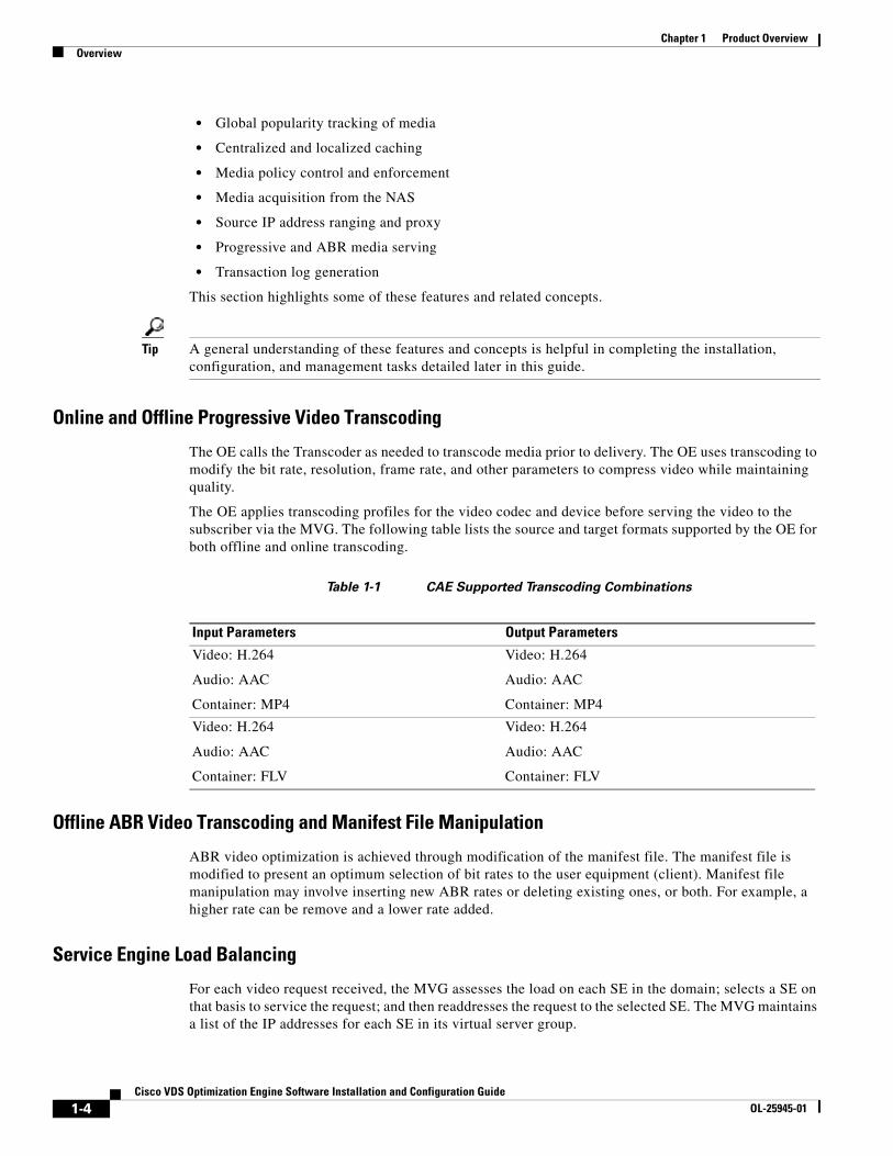
The OE applies transcoding profiles for the video codec and device before serving the video to the subscriber via the MVG. The following table lists the source and target formats supported by the OE for both offline and online transcoding.
Table 1-1 CAE Supported Transcoding Combinations
Offline ABR Video Transcoding and Manifest File Manipulation
ABR video optimization is achieved through modification of the manifest file. The manifest file is modified to present an optimum selection of bit rates to the user equipment (client). Manifest file manipulation may involve inserting new ABR rates or deleting existing ones, or both. For example, a higher rate can be remove and a lower rate added.
Service Engine Load Balancing
For each video request received, the MVG assesses the load on each SE in the domain; selects a SE on that basis to service the request; and then readdresses the request to the selected SE. The MVG maintains a list of the IP addresses for each SE in its virtual server group.
Input Parameters Output Parameters
Video: H.264
Audio: AAC
Container: MP4
Video: H.264
Audio: AAC
Container: MP4
Video: H.264
Audio: AAC
Container: FLV
Video: H.264
Audio: AAC
Container: FLV

1-5Cisco VDS Optimization Engine Software Installation and Configuration Guide
OL-25945-01
Chapter 1 Product OverviewOverview
Global Popularity Tracking of Media
While serving video to subscribers, the OE tracks the popularity of the video based on the number of requests received for that asset in a given time period. When a particular video asset reaches a popularity threshold, the OFAM that manages the asset performs offline transcoding of the asset. When multiple OFAMs are deployed in the network, the popularity counters collected by each individual OFAM are aggregated into a master database on the CDSM node.
Centralized and Localized Caching
If a particular video meets a popularity threshold through repeated requests, the OE acquires the video from the original website, transcodes it, and saves it to a centralized NAS. When the SE serves the video for the first time, it acquires the video from the NAS and saves it to its local cache. For any subsequent video requests, the SE acquires the video from its local cache.
If the requested video is not in cache but meets a predefined popularity threshold, the SE not only orders real-time (online) transcoding of the video received from the origin server, but also triggers the OFAM to perform offline transcoding to create one or more cached copies of the video.
Media Policy Control and Enforcement
Media policy control and enforcement determines how video assets are transcoded and served, based on the following criteria:
• Adaptation Profile Index, based on subscriber service level
• Device Class, based on device capabilities
• Source content, identified by matching domain name
• Input video bit rate
• Input video frame rate
• Input video resolution
• Container format
• Video codec employed
• Whether transcoding is to be online or offline
• Whether the content provider is a partner of the service provider
• Whether the request falls into the configured blacklist or whitelist

1-6Cisco VDS Optimization Engine Software Installation and Configuration Guide
OL-25945-01
Chapter 1 Product OverviewOverview
Support for Radio Access Technology (RAT)
Different types of radio access technology (RAT) or access networks can support different network bandwidths. This makes it necessary for the OE to use the access network type as one criterion when performing content adaptation. To support RAT, the MVG should be able to idenfity the RAT type on a per-subscription or per-session basis and send that information to the OE in the form of an X-header for related HTTP GET requests.
Support for 3GP and 3G2 Video
VDS-OE allows 3GP and 3G2 video content (3GPP and 3GPP2 file formats) to be tracked for popularity and, after reaching a predefined threshold, cached in NAS or local storage for offline serving. Because 3GP and 3G2 video is already of low quality, VDS-OE does not attempt to further optimize the video, as this would usually lead to video of unacceptable quality. Even so, local caching allows for bandwidth savings in the core network.
Media Acquisition from the NAS
The OE NAS stores both transcoded video files and ABR manifest files. These files are not removed by the SE. Instead, the OFAM deletes files from NAS in accordance with the following deletion criteria:
• The OFAM keeps an expiration timer for transcoded video, and deletes files after they expire.
• The OFAM employs a NAS eviction mechanism that works to prevent the storage capacity of the NAS from falling below a configured “high watermark” threshold (75% by default). This ensures that there is always room in the NAS for new input or output files.
• The OFAM database includes entries for last access time that can serve as triggers for eviction of files that have not been used recently. The OFAM also periodically checks for and deletes any “dangling” files, which are files that no longer have a database entry.
Note While the SE cannot delete expired content from the NAS, the content cached in local storage is deleted automatically when the hit count (number of times the content is accessed) reaches a predefined storage threshold.
Source IP Address Ranging and Proxy
As a security measure, some websites may deny service to a source that makes a large number of requests from the same IP address. To avoid this potential issue, the OE can be configured to perform IP address ranging, in which it selects one of up to 24 different IP addresses for use by the SE when making requests to a website.
Progressive and ABR Media Serving
The OE transcodes and serves both progressive and ABR video based on media policy and popularity settings. Progressive video is transcoded and served online until popularity thresholds are met; once met, the video is transcoded, cached, and served offline.
For ABR video, video chunks of different bit rates are added or deleted from original video and cached for serving after the popularity threshold has been reached. The manifest file is modified to remove or add video bit rates. New video rates are generated through transcoding.

1-7Cisco VDS Optimization Engine Software Installation and Configuration Guide
OL-25945-01
Chapter 1 Product OverviewOverview
Master Database Failover and Backup/Restore
The OE can scale to include multiple OFAMs. This is accomplished by maintaining a centralized master database to which all OFAM local databases are synchronized. By default, the master database server runs on the CDSM nodes.
Such a centralized database serves two purposes:
• Aggregates the hit count across multiple OFAMs so that offline transcoding is triggered in a predictable way.
• Allows content that was offline-transcoded by one OFAM to be served by another OFAM.
By default, the OFAM always connects to the master database on the primary CDSM. After a manual switchover of CDSMs, the OFAM should connect to the master database on the new primary CDSM.
The OFAM is designed to use multiple connections to connect to the master database for transaction throughput. The OFAM generates an alarm if its connection to the master is lost, and then clears the alarm when the connection is restored.
Managed Domain Services
VDS-OE supports optimization of both managed and OTT content. Managed content domains must be configured on the CDSM as delivery services. Each delivery service must have an associated content origin from which to retrieve video content.
VDS-OE does not support a content delivery network (CDN) or similar hierarchy. Instead, the SE receiving the request matches on a delivery service and acquires content directly from the corresponding content origin. For additional information, see Chapter 5 of the CDS-IS 2.6 User Guide.
The CDS-IS service router (SR) can be used to provide load balancing for managed domains. For additional information on the SR, refer to the Content Delivery System overview in Chapter 1 of the CDS-IS 2.6 User Guide.
Managed Domain Services Workflow
The basic sequence of events for managed domain content retrieval are as follows:
1. A client requests a video associated with a managed domain; for example, http://service.mydomain.com/video.mp4. The DNS resolves this to the SR associated with the mydomain.com delivery service.
2. The request to the SR is routed through the MVG. Although the MVG identifies it as video content, it also identifies it as a managed domain and so does not readdress the request. Instead, it is routed to the SR as normal.
3. The SR performs a 302 redirect to the URL http://service.mydomain.com/video.mp4. Once again, the request is routed through the MVG and, as before, is routed straight through to the SE.
4. On the OE, the domain name portion (mydomain.com) is extracted and used to look up the delivery service for the corresponding origin domain name. The SE substitutes the origin domain name into the URL and continues with normal SE flow for OTT content. If no domain server is found, the request proceeds as with normal OTT content, but without the mapping.
A variation of this sequence occurs when the SR is configured as an Authoritative DNS server. In this case:
1. A client requests a video associated with a managed domain; for example, http://service.mydomain.com/video.mp4. The SR Authoritative DNS eventually gets the request and resolves the request directly to one of the SEs.
1-8Cisco VDS Optimization Engine Software Installation and Configuration Guide
OL-25945-01
Chapter 1 Product OverviewOverview
2. The client gets the resolved address and issues a request of http://SE1.SE.service.mydomain.com/video.mp4. Once again, the request is routed through the MVG and, as before, is routed straight through to the SE.
3. On the OE, the domain name portion (mydomain.com) is extracted and used to look up the delivery service for the corresponding origin domain name. The SE (Web Engine) substitutes the origin domain name into the URL and continues with normal SE flow for OTT content. If no domain server is found, the request proceeds as with normal OTT content, but without the mapping.
Transaction Log Generation
For each video served, a Transaction Log is generated and stored in the OE file system. Both Extended Squid and Apache CLF formats are supported. Transaction Logs can be reviewed using the web application AnalysisUtility tool, and can be archived and uploaded to an external FTP server. For more information, refer to the CDS-IS 2.6 Sofware Configuration Guide.
Sample OE WorkflowsThe following sample workflows show how video content is served in a variety of representative use cases.
Request for Cached Progressive Video
In this scenario, we assume that a user device has requested a progressive video file that has already been transcoded and cached by the OE through a previous offline transcoding session. The following events take place:
1. A user device sends an HTTP GET request for the video.
2. The MVG receives the user request and, using DPI, determines that it is a request for video. The MVG then refers to its OE load-balancing scheme to select an active SE, and forwards the HTTP request to the selected SE.
3. The SE receives the request from the MVG and verifies through the OFAM that a video meeting the necessary device and policy requirements is cached. If a suitable video is cached, the SE retrieves the video from the location specified by the OFAM and sends it to the MVG.
4. The MVG receives the video from the SE and forwards the video to the user device.
Video Served from the NAS and Saved to Local Cache
When the OE receives a request for a popular video, it acquires the video from the original website, transcodes it, and saves it to the NAS. When the SE serves the video for the first time, it acquires the video from the NAS and saves it to its local cache. For any subsequent video requests, the SE acquires the video from its local cache.
Request for Uncached Progressive Video
In this scenario, we assume that a video is requested that is not available either in the NAS or in the local cache, and so must be served from the original website with online (real-time) transcoding applied. The following events take place:
1. A user device sends an HTTP GET request for the video.
1-9Cisco VDS Optimization Engine Software Installation and Configuration Guide
OL-25945-01
Chapter 1 Product OverviewOverview
2. The MVG receives the user request and, using DPI, determines that it is a request for video. The MVG then refers to its OE load-balancing scheme to select an active SE, and forwards the HTTP request to the selected SE.
3. The SE receives the HTTP request from the MVG and determines through the OFAM that the requested video is not cached. The OFAM also finds that the requested video does not meet the predefined popularity threshold, and so does not initiate offline transcoding of the video.
4. The SE receives the video from the origin server and submits it to the Transcoder with a request to perform online (real-time) transcoding of the video in a specific format and bit rate.
5. The Transcoder transcodes the video in the specified format and bit rate and returns the transcoded video data to the SE, which in turn sends the transcoded video data to the MVG.
6. The MVG receives the video from the SE and forwards the video to the user device.
Request for Progressive Video Not in Cache, but Popular
If the requested video is not in cache but meets a predefined popularity threshold, the OE orders online transcoding of the video it receives from the origin server, and also orders offline transcoding to create one or more cached copies of the video. In this case, the workflow is as described above, but with an additional process that proceeds in parallel as follows:
1. The OFAM determines that the video is popular, downloads the video from the origin server, and submits a video transcosing request to the Transcoder to perform offline transcoding of the video in a specified format and bit rate.
2. The Transcoder selects an encode node based on its own configuration and load-balancing mechanism, transcodes the video as requested, and saves the output files to the specified NAS directory.
3. The OE receives a notification from the Transcoder that the transcode job is finished, and in response, updates the state of the database record for the transcoded video asset to READY.
Request for Cached ABR (HLS) Video
In this scenario, we assume that an ABR video is requested that is already cached in the OE. The following events take place:
1. The user device sends an HTTP GET request for an HLS playlist corresponding to the ABR video.
2. The MVG receives the user request and, using DPI, determines that this is a request for video. It then refers to its OE load-balancing scheme to select an active SE, adds information relevant to the ABR video to the HTTP request, and forwards the HTTP request to the selected SE.
3. The SE receives the HTTP request from the MVG and determines through the OFAM that the requested playlist is cached, and requests the playlist from the local cache or NAS.
4. The SE receives the playlist, which has been modified by the CAE, from the OFAM and forwards it to the MVG. The MVG, in turn, forwards the OE-modified playlist to the user device.
5. The user device returns repeated HTTP requests to the MVG for the ABR segments required to play the entire video. The MVG, in turn, sends repeated requests to the SE, which provides the ABR segments as they are requested.
ABR (HLS) Video Not in Cache, but Popular
The OE currently does not support online (real time) transcoding of ABR video. Therefore, if a requested ABR video is determined to meet a predefined popularity threshold, the OE retrieves the video content directly from the origin server.

1-10Cisco VDS Optimization Engine Software Installation and Configuration Guide
OL-25945-01
Chapter 1 Product OverviewOverview

C H A P T E R
2-1Cisco VDS Optimization Engine Software Installation and Configuration Guide
OL-25945-01
2Installing the VDS-OE
OverviewThis chapter describes system requirements and design considerations for the OE and provides instructions for installing the OE and related software.
Hardware PlatformThe OE and its required CDSM management system run on the Cisco UCS hardware platform. The installation is implemented on the 1RU Cisco UCS C-series chassis. A typical OE hardware configuration includes the following:
• Cisco UCS C-series with:
– Hyperthreading enabled
– Two 10 Gigabit unified fabric
– Eight (8) hard disks in RAID5 configuration
– 48 GB DDR3 memory
• UCS blade servers for CTM
• NAS
This platform can be used as the hosting environment for the CDSM, OFAM, and SE together, or for the SE alone with CDSM and OFAM installed on a different server. These two options benefit from slightly different hardware configurations. The SE alone requires substantial local storage for caching video content. The maximum local storage currently provided on UCS C-Series blades is about 1.2 TB. Typically, the SE is implemented on a C220 M3 with eight 300 GB hard disks.
Tip Consult Cisco UCS product information for current disk and configuration settings.
Although 48 GB DDR3 memory is the nominal recommended configuration, the C220 M3 supports up to 384 GB of memory, so much more can be added if desired. Additional memory allows more streaming content to remain in memory, thereby optimizing transcoding node utilization and thus yielding higher overall performance.

2-2Cisco VDS Optimization Engine Software Installation and Configuration Guide
OL-25945-01
Chapter 2 Installing the VDS-OEHardware Platform
Like the SE and CDSM, the CTM is typically installed on a UCS blade server. A typical installation may have 10 or more transcoder blades for every OFAM or SE installed. Ideally, the transcoders are installed in a UCS chassis and are managed collectively by UCS Manager. Otherwise, the transcoders can also run independently on individual C Series chassis.
Transcoded video is saved either to the NAS or to the OE local disk. Total space requirement for video can be estimated as follows:
• Space required = number of videos * average video rate * average duration
For example, a 15-TB storage array can hold 100,000 six-minute videos encoded at 500 Kb/s average.
Figure 2-1 shows the basic configuration for CDSM, OFAM, SE, and CTM hardware.
Figure 2-1 CAE Solution Components
Requirements for RedundancyThe CDSM and the OFAM support redundancy. A redundant CDSM and OFAM can be added by installing another UCS C-series blade server.
CAE Controller CAE EncoderOffline/Online TranscodingVM1: CDSM-ACT/STBY
O&M for CAE-Controller
VM2: CAE-OFAM-ACT/STBY Centralized database Popularity tracking
Manage Offline transcoding
Armada LBACT/SBY
Transcoders
VM1: CAE-SE Handle requests from MVG Compute Video signature Manage Online transcoding Stream video from offline content
Stream video after online transcoding
UCS SFF C220 M3 :- 2 * E5-2640 Intel Sandy Bridge 6 core - 64 Gb DDR3 memory- 2 * 10 Gbps network cards- 8 * 1TB SFF hard disks
MVG
Netapp NASCentralized Storage
OS
UCS B200 M3 :- 2.96 GHz E5-2690 Intel 8 core - 8x4 Gb DDR3 memory- 2 * 10 Gbps network cards
Control planeOffline data planeOnline data plane
Management
3201
77
2-3Cisco VDS Optimization Engine Software Installation and Configuration Guide
OL-25945-01
Chapter 2 Installing the VDS-OEHardware Platform
OFAM Redundancy
Video asset information is maintained in the Asset Information Manager (AIM) within the OFAM. Scalability and redundancy are acheived through multiple AIMs, with synchronization maintained through the Master AIM Database contained in CDSM. A backup copy of the Master Database is kept in the standby CDSM. Refer to the Cisco Content Delivery Engine 205/220/250/420/460 Hardware Installation Guide for additional information on redundancy.
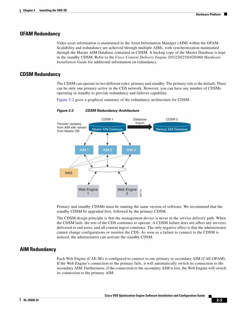
CDSM Redundancy
The CDSM can operate in two different roles: primary and standby. The primary role is the default. There can be only one primary active in the CDS network. However, you can have any number of CDSMs operating in standby to provide redundancy and failover capability.
Figure 2-2 gives a graphical summary of the redundancy architecture for CDSM.
Figure 2-2 CDSM Redundancy Architecture
Primary and standby CDSMs must be running the same version of software. We recommend that the standby CDSM be upgraded first, followed by the primary CDSM.
The CDSM design principle is that the management device is never in the service delivery path. When the CDSM fails, the rest of the CDS continues to operate. A CDSM failure does not affect any services delivered to end users, and all content ingest continues. The only negative effect is that the administrator cannot change configurations or monitor the CDS. As soon as a failure to connect to the CDSM is noticed, the administartor can activate the standby CDSM.
AIM Redundancy
Each Web Engine (CAE-SE) is configured to connect to one primary or secondary AIM (CAE-OFAM). If the Web Engine’s connection to the primary fails, it will automatically switch its connection to the secondary AIM. Furthermore, if the connection to the secondary AIM is lost, the Web Engine will switch its connection to the primary AIM.
CDSM 1 DatabaseImportPeriodic Updates
from AIM with refreshfrom Master DB Master AIM Database
CDSM 2
Backup AIM Database
Web Engine1
Web Engine2
NAS
AIM 1 AIM 2 AIM 3
3201
78
2-4Cisco VDS Optimization Engine Software Installation and Configuration Guide
OL-25945-01
Chapter 2 Installing the VDS-OEOperating System Requirements
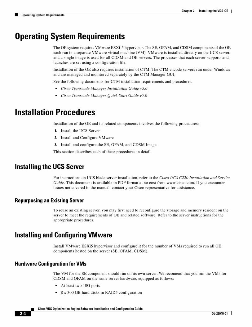
Operating System RequirementsThe OE system requires VMware ESXi-5 hypervisor. The SE, OFAM, and CDSM components of the OE each run in a separate VMware virtual machine (VM). VMware is installed directly on the UCS server, and a single image is used for all CDSM and OE servers. The processes that each server supports and launches are set using a configuration file.
Installation of the OE also requires installation of CTM. The CTM encode servers run under Windows and are managed and monitored separately by the CTM Manager GUI.
See the following documents for CTM installation requirements and procedures.
• Cisco Transcode Manager Installation Guide v5.0
• Cisco Transcode Manager Quick Start Guide v5.0
Installation ProceduresInstallation of the OE and its related components involves the following procedures:
1. Install the UCS Server
2. Install and Configure VMware
3. Install and configure the SE, OFAM, and CDSM Image
This section describes each of these procedures in detail.
Installing the UCS ServerFor instructions on UCS blade server installation, refer to the Cisco UCS C220 Installation and Service Guide. This document is available in PDF format at no cost from www.cisco.com. If you encounter issues not covered in the manual, contact your Cisco representative for assistance.
Repurposing an Existing Server
To reuse an existing server, you may first need to reconfigure the storage and memory resident on the server to meet the requirements of OE and related software. Refer to the server instructions for the appropriate procedures.
Installing and Configuring VMwareInstall VMware ESXi5 hypervisor and configure it for the number of VMs required to run all OE components hosted on the server (SE, OFAM, CDSM).
Hardware Configuration for VMs
The VM for the SE component should run on its own server. We recomend that you run the VMs for CDSM and OFAM on the same server hardware, equipped as follows:
• At least two 10G ports
• 8 x 300 GB hard disks in RAID5 configuration

2-5Cisco VDS Optimization Engine Software Installation and Configuration Guide
OL-25945-01
Chapter 2 Installing the VDS-OEInstallation Procedures
• At least 48 GB DDR3 memory
• Hyperthreading enabled
Installing VMs on Cisco Servers
Detailed instructions for installing VMware on Cisco C-Series servers is provided in the Cisco UCS C-Series Servers VMware Installation Guide.
This document is available in PDF format at no cost from www.cisco.com. The sections most relevant for OE installation are “VMware vSphere ESXi Installation” and “RAID Controller Considerations.” These sections may be downloaded separately from the following URLs:
• http://www.cisco.com/en/US/docs/unified_computing/ucs/os-install-guides/vmware/CSERIES-VMWARE_chapter_011.pdf
• http://www.cisco.com/en/US/docs/unified_computing/ucs/os-install-guides/vmware/CSERIES-VMWARE_appendix_0101.pdf
Note Be sure to select RAID-5 when setting up the hard disks for the server. This means that, for the UCS C220M3 with eight hard disks, these hard disks will be presented as one virtual disk.
Configuring Ports as Pass-Through Devices
For optimum performance, the 10G ports on the SE servers must be configured as pass-through devices. To configure these ports, do the following:
Step 1 Launch the VMware vSphere Client application.
Step 2 From the Inventory listing, choose the ESX host that is to be configured.
Step 3 In the Configuration tab, click Advanced Settings. The Pass-through Configuration page is displayed, listing the available pass-through devices (ports).
Step 4 Click Edit, then select the devices to be configured.
Step 5 Click OK, and confirm that the icon by each device selected has changed from green to orange, indicating changed status.
Step 6 Reboot the server, return to the Pass-through Configuration page, and confirm that the icons for all devices selected has changed from orange to green, indicating enabled and active status.
Installing VM Components
The SE, OFAM, and CDSM components of OE install in separate VMs. The OE installation includes two Open Virtual Appliance (OVA) files, one for the SE and one for OFAM and CDSM:
• VDSOE_SE.ova
• VDSOE_OFAM_CDSM.ova
Each OVA file installs on the VMware ESXi host on the Cisco UCS server using the VMware vSphere client software.
Default VM settings in the OVA file are as follows:
• 5 disks
2-6Cisco VDS Optimization Engine Software Installation and Configuration Guide
OL-25945-01
Chapter 2 Installing the VDS-OEInstallation Procedures
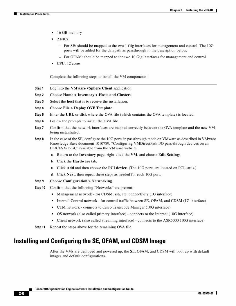
• 16 GB memory
• 2 NICs:
– For SE: should be mapped to the two 1 Gig interfaces for management and control. The 10G ports will be added for the datapath as passthrough in the description below.
– For OFAM: should be mapped to the two 10 Gig interfaces for management and control
• CPU: 12 cores
Complete the following steps to install the VM components:
Step 1 Log into the VMware vSphere Client application.
Step 2 Choose Home > Inventory > Hosts and Clusters.
Step 3 Select the host that is to receive the installation.
Step 4 Choose File > Deploy OVF Template.
Step 5 Enter the URL or disk where the OVA file (which contains the OVA template) is located.
Step 6 Follow the prompts to install the OVA file.
Step 7 Confirm that the network interfaces are mapped correctly between the OVA template and the new VM being instantiated.
Step 8 In the case of the SE, configure the 10G ports in passthrough mode on VMware as described in VMware Knowledge Base document 1010789, “Configuring VMDirectPath I/O pass-through devices on an ESX/ESXi host,” available from the VMware website.
a. Return to the Inventory page, right-click the VM, and choose Edit Settings.
b. Click the Hardware tab.
c. Click Add and then choose the PCI device. (The 10G ports are located on PCI cards.)
d. Click Next, then repeat these steps as needed for each 10G port.
Step 9 Choose Configuration > Networking.
Step 10 Confirm that the following “Networks” are present:
• Management network - for CDSM, ssh, etc. connectivity (1G interface)
• Internal Control network - for control traffic between SE, OFAM, and CDSM (1G interface)
• CTM network - connects to Cisco Transcode Manager (10G interface)
• OS network (also called primary interface) - connects to the Internet (10G interface)
• Client network (also called streaming interface) - connects to the ASR5000 (10G interface)
Step 11 Repeat the steps above for the remaining OVA file.
Installing and Configuring the SE, OFAM, and CDSM ImageAfter the VMs are deployed and powered up, the SE, OFAM, and CDSM will boot up with default images and default configurations.

2-7Cisco VDS Optimization Engine Software Installation and Configuration Guide
OL-25945-01
Chapter 2 Installing the VDS-OEInstallation Procedures
Configuring the SE
Step 1 Configure the following interfaces:
• Management network
• Internal Control Network
• Client network (Streaming interface)
• Origin Server Network (Primary Interface)
• CTM Network
– Interface TenGigabitEthernet x/0
– Ip address <ip address> <mask>
– Exit
Step 2 Configure the default gateway:
• ip default-gateway <ip address>
Step 3 Configure the DNS server:
• ip name-server <ip address>
Step 4 Configure the primary and streaming interfaces:
• Primary-interface <interface>
• Streaming-interface <interface>
Step 5 Save the configuration:
• Write memory
Step 6 Reload.
Step 7 Configure the CDSM IP address:
• cdsm ip <cdsm ip address or hostname>
Step 8 Enable the CMS process:
• cms enable
Step 9 Save the configuration:
• Write memory
Step 10 Configure SE features from the CDSM as needed.
Configuring the OFAM
Step 1 Configure the following Interfaces:
• Management network
• Internal Control network
Step 2 Configure the default gateway:
• ip default-gateway <ip address>
Step 3 Configure the DNS server:

2-8Cisco VDS Optimization Engine Software Installation and Configuration Guide
OL-25945-01
Chapter 2 Installing the VDS-OEInstallation Procedures
• ip name-server <ip address>
Step 4 Configure the primary interfaces:
• Primary-interface <interface>
Step 5 Save the configuration:
• Write memory
Step 6 Reload.
Step 7 Configure the CDSM IP address:
• cdsm ip <cdsm ip address or hostname>
Step 8 Enable the CMS process:
• cms enable
Step 9 Enable OFAM mode to start up OFAM services:
• cae ofam-mode enable
Step 10 Save the configuration:
• write memory
Step 11 Configure the OFAM features from CDSM as needed.
Configuring the CDSM
CDSM is the management system for OE. CDSM runs on a separate VM; we recommend installing it on the same UCS server as the OFAM and its VM.
Step 1 Configure the following Interfaces:
• Management network
• Internal Control network
Step 2 Configure the default gateway:
• ip default-gateway <ip address>
Step 3 Configure the DNS server:
• ip name-server <ip address>
Step 4 Configure the primary interfaces:
• primary-interface <interface>
Step 5 Change the device mode:
• device mode content-delivery-system-manager
Step 6 Save the configuration:
• write memory
Step 7 Reload.
Step 8 Enable the CMS process:
• cms enable
Step 9 Save the configuration:
• write memory
C H A P T E R
3-1Cisco VDS Optimization Engine Software Installation and Configuration Guide
OL-25945-01
3Configuring the VDS-OE
OverviewYou must configure the OE before using it for video content delivery. This chapter explains how to perform OE configuration using CDSM.
The goals of OE configuration are:
• To establish correct operating parameters for the OE hardware
• To define the IP interfaces through which the OE interacts with the network
• To configure basic operating parameters for video transcoding and delivery
The OE allows operators to use both CDSM GUI and CLI command interfaces. Where both GUI and CLI methods exist, they are equivalent and synchronized. In fact, CDSM GUI operation is implemented by remotely executing the corresponding CLI command on a particular OE node. When using the OE together with VDS-IS, we recommend using the CDSM GUI where possible, as this allows the two applications to share a common control interface.
Tip This chapter describes procedures using the CDSM GUI. For information on using CLI commands in CDSM, see the CLI Commands appendix.
Note The CDSM supports two types of configurations, global and device. With both types of configurations, commands are downloaded from the CDSM to the device. With global configuration, commands are synchronized to the CDSM when changed on the device.
Using the CDSMThis section provides a brief overview of using the CDSM GUI. For additional information, see the relevant portions of the Cisco Internet Streamer CDS 2.6 Software Configuration Guide (OL-23609-01).
3-2Cisco VDS Optimization Engine Software Installation and Configuration Guide
OL-25945-01
Chapter 3 Configuring the VDS-OEUsing the CDSM
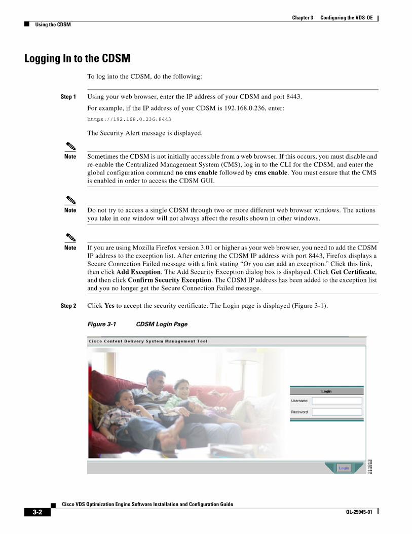
Logging In to the CDSMTo log into the CDSM, do the following:
Step 1 Using your web browser, enter the IP address of your CDSM and port 8443.
For example, if the IP address of your CDSM is 192.168.0.236, enter:
https://192.168.0.236:8443
The Security Alert message is displayed.
Note Sometimes the CDSM is not initially accessible from a web browser. If this occurs, you must disable and re-enable the Centralized Management System (CMS), log in to the CLI for the CDSM, and enter the global configuration command no cms enable followed by cms enable. You must ensure that the CMS is enabled in order to access the CDSM GUI.
Note Do not try to access a single CDSM through two or more different web browser windows. The actions you take in one window will not always affect the results shown in other windows.
Note If you are using Mozilla Firefox version 3.01 or higher as your web browser, you need to add the CDSM IP address to the exception list. After entering the CDSM IP address with port 8443, Firefox displays a Secure Connection Failed message with a link stating “Or you can add an exception.” Click this link, then click Add Exception. The Add Security Exception dialog box is displayed. Click Get Certificate, and then click Confirm Security Exception. The CDSM IP address has been added to the exception list and you no longer get the Secure Connection Failed message.
Step 2 Click Yes to accept the security certificate. The Login page is displayed (Figure 3-1).
Figure 3-1 CDSM Login Page
3-3Cisco VDS Optimization Engine Software Installation and Configuration Guide
OL-25945-01
Chapter 3 Configuring the VDS-OEUsing the CDSM
Step 3 Enter the Username and Password, then click Login. The CDSM home page is displayed.
Note When logging into the CDSM for the first time, do not set your browser to remember your CDSM username and password. Doing so would cause the browser to remember the default admin username and password, which you should change as soon as possible.
Note The built-in username is admin and the initial password is default. We strongly recommend that you change the built-in admin password as soon as possible. To do so, log in to the CLI of the CDSM device, and use the username admin password <password> global configuration command.
Note If the default username and password have been changed by another CDSM administrator, you need to get the new username and password.

3-4Cisco VDS Optimization Engine Software Installation and Configuration Guide
OL-25945-01
Chapter 3 Configuring the VDS-OEUsing the CDSM
Navigating the CDSMThe following illustration shows the different elements in the CDSM GUI.
Figure 3-2 CDSM Graphical User Interface
The System Status bar, tab, tab options, and tools are accessible from any page in the CDSM. The left panel menu changes depending on which tab and tab option you choose.
For additional information on using the CDSM interface, see the Cisco Internet Streamer CDS 2.6 Software Configuration Guide (OL-23609-01).
1 Left panel menu 5 System Status bar
2 Tab options 6 Page
3 Tabs 7 Submit and Cancel buttons
4 Task bar 8 Tools (Home, Help, and Logout)

3-5Cisco VDS Optimization Engine Software Installation and Configuration Guide
OL-25945-01
Chapter 3 Configuring the VDS-OEActivating and Synchronizing Devices
Activating and Synchronizing DevicesAs the OE administrator, you approve a device for use in the system by making it active. This security features prevents unauthorized devices from joining the system.
Synchronization ensures accurate timestamps in all the logs and accuracy in caching decisions determined by If Modifed Since (IMS) lookups. Using Network Time Protocol (NTP) to synchronize the devices in the system is the best practice.
Note If the network is not configured with NTP, then every device in the CDS must be configured with exactly the same time and time zone. We recommend that you use an NTP server for network synchronization.
Caution All devices must be synchronized with each other for the system to work properly.
Activating and Setting NTP for Each DeviceTo navigate within the CDSM, click one of the tabs (for example, Devices) and then one of the tab options (for example, Locations). Navigational directions in the followg procedures are written as shown in the following example:
Devices > Devices > Assignments > Device Groups
Note From the Devices Table, you can activate all inactive devices by clicking the Activate All Inactive SEs icon.
To activate and synchronize a Service Engine (SE), do the following:
Step 1 From the CDSM home page, choose Devices > Devices. The Devices table is displayed listing all the registered SEs.
Figure 3-3 Devices Table Page – Edit Device
Step 2 Click the Edit icon next to the device name. The Devices home page is displayed.
3-6Cisco VDS Optimization Engine Software Installation and Configuration Guide
OL-25945-01
Chapter 3 Configuring the VDS-OEActivating and Synchronizing Devices
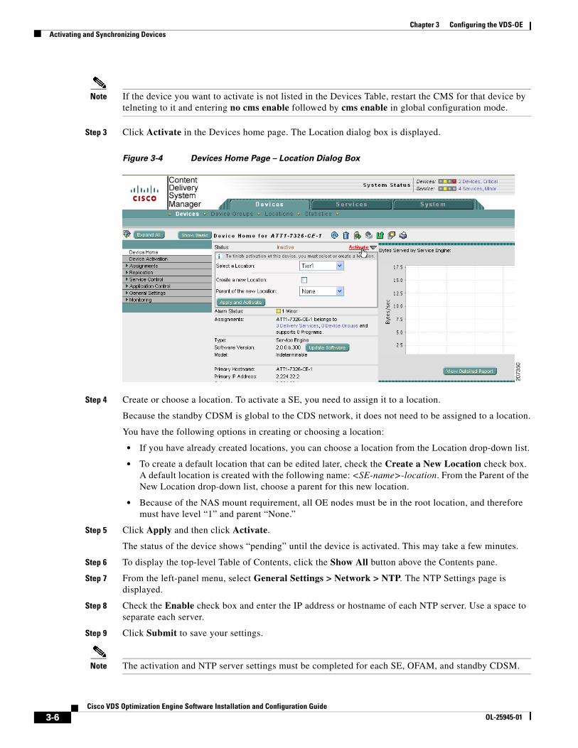
Note If the device you want to activate is not listed in the Devices Table, restart the CMS for that device by telneting to it and entering no cms enable followed by cms enable in global configuration mode.
Step 3 Click Activate in the Devices home page. The Location dialog box is displayed.
Figure 3-4 Devices Home Page – Location Dialog Box
Step 4 Create or choose a location. To activate a SE, you need to assign it to a location.
Because the standby CDSM is global to the CDS network, it does not need to be assigned to a location.
You have the following options in creating or choosing a location:
• If you have already created locations, you can choose a location from the Location drop-down list.
• To create a default location that can be edited later, check the Create a New Location check box. A default location is created with the following name: <SE-name>-location. From the Parent of the New Location drop-down list, choose a parent for this new location.
• Because of the NAS mount requirement, all OE nodes must be in the root location, and therefore must have level “1” and parent “None.”
Step 5 Click Apply and then click Activate.
The status of the device shows “pending” until the device is activated. This may take a few minutes.
Step 6 To display the top-level Table of Contents, click the Show All button above the Contents pane.
Step 7 From the left-panel menu, select General Settings > Network > NTP. The NTP Settings page is displayed.
Step 8 Check the Enable check box and enter the IP address or hostname of each NTP server. Use a space to separate each server.
Step 9 Click Submit to save your settings.
Note The activation and NTP server settings must be completed for each SE, OFAM, and standby CDSM.
3-7Cisco VDS Optimization Engine Software Installation and Configuration Guide
OL-25945-01
Chapter 3 Configuring the VDS-OEActivating and Synchronizing Devices
Tip For a quick way to get to other SEs, click the Display All Devices icon located to the left of the Expand All button. This icon toggles between the Display All Devices and Menu icons.
For more detailed information about activating devices and configuring locations and NTP servers, see the Cisco Internet Streamer CDS 2.6 Software Configuration Guide (OL-23609).
Activating All Inactive Service Engines
To activate all inactive SEs, do the following:
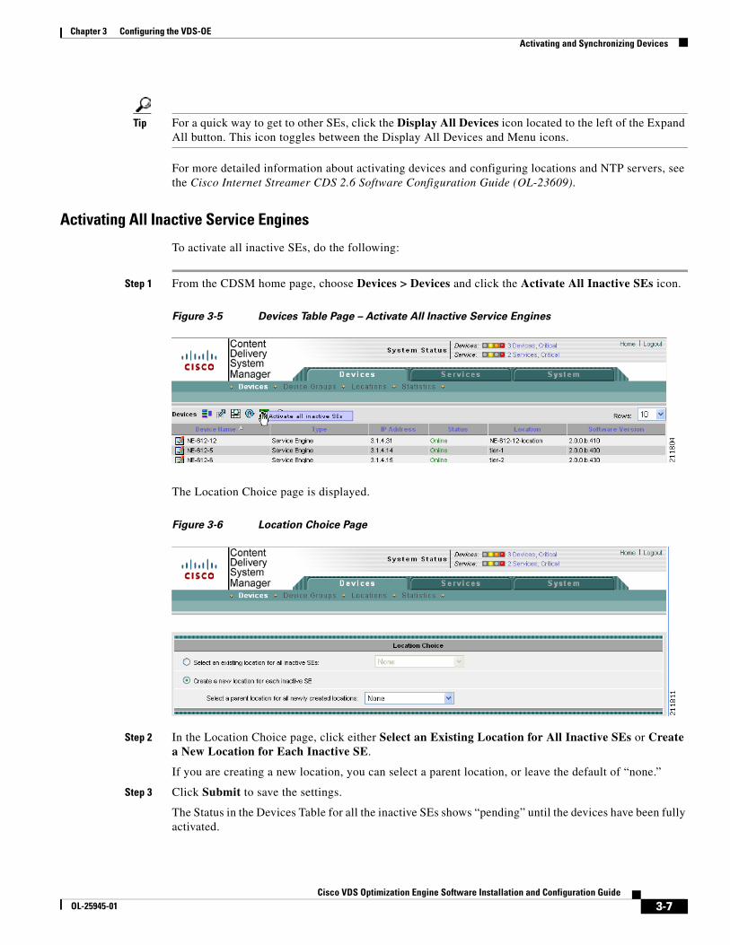
Step 1 From the CDSM home page, choose Devices > Devices and click the Activate All Inactive SEs icon.
Figure 3-5 Devices Table Page – Activate All Inactive Service Engines
The Location Choice page is displayed.
Figure 3-6 Location Choice Page
Step 2 In the Location Choice page, click either Select an Existing Location for All Inactive SEs or Create a New Location for Each Inactive SE.
If you are creating a new location, you can select a parent location, or leave the default of “none.”
Step 3 Click Submit to save the settings.
The Status in the Devices Table for all the inactive SEs shows “pending” until the devices have been fully activated.

3-8Cisco VDS Optimization Engine Software Installation and Configuration Guide
OL-25945-01
Chapter 3 Configuring the VDS-OEConfiguring the System and Devices
Note All devices activated in this way need to have the NTP settings configured, as described previously in the Activating and Setting NTP for Each Device section.
Synchronizing Clocks for OE DevicesWe recommend synchronizing the clocks for all devices involved in the OE. This helps to ensure that all timestamps in the AIM database are accurate and that all “update” and “sync” mechanisms function properly.
To synchronize the clocks for all OE devices, do the following:
Step 1 In SE, OFAM, and CDSM (in any sequence), configure the NTP server and time zone. For example:
NTP server 171.68.10.150clock timezone PDT -7 0.
Step 2 From any Linux management console:
a. Open the NTP port in your firewall.
b. In /etc/ntp.conf, add the IP address of the NTP server wherever the server pool is listed.
c. In /etc/ntp/step-tickers, add the IP address of the NTP server.
d. Run “ntpdate -dv <ntp-server-ip-address>” to synchronize the clocks.
Note The synchronization process usually takes 10 to 15 minutes to complete.
e. When the synchronization process is complete, run “hwclock --systohc” so that the system will acquire the new time on reboot.
Step 3 On the CTM Windows server:
a. Navigate to Control Panel > Date and Time > Internet Time > Change Settings.
b. Enter the IP address of the NTP server as the time server.
c. Confirm that the Synchronize... checkbox is checked.
d. Click Update Now.
Upon reboot, the clocks for all OE devices will be synchronized to the specified NTP server.
Configuring the System and DevicesAfter you have completed activating and configuring the NTP servers for all the devices in the CDSM, you are ready to configure the OE for video content delivery.
Configuring the OE involves both system configuration tasks and device configuration tasks.
3-9Cisco VDS Optimization Engine Software Installation and Configuration Guide
OL-25945-01
Chapter 3 Configuring the VDS-OEConfiguring the System and Devices
System Configuration Tasks
System configuration involves registering (uploading) the following files:
• Content Adaptation File — A user-defined content adaptation file must be uploaded to the CDSM. CDSM ships with a default Content Adaptation XML file (factory.xml), which defines the rules by which OE optimizes and transcodes video assets. If needed, the operator can register a non-default Content Adaptation File.
• NAS File — Must be created in an XML text editor, registered or uploaded to CDSM, and associated with a Content Origin (delivery service). All OE nodes (except CDSM) must access the NAS device for offline transcoded content. A NAS XML file is registered with the CDSM to specify how the NAS should be mounted to the OE nodes.
A sample NAS XML file is shown below.
<?xml version=”1.0”?><CdsOrigin><server name="nas1" host="192.168.252.67"/><server name="nas2" host="192.168.252.68"/><sourceNFS name="NAS" sharePoint="nas_nfs" access="ro" maxRetry="10" rsize="131072"/><localMount name="localMount" mountPoint="vod" source="NAS" num-of-mounts="2"order="fcfs" serverList="nas1, nas2"/></CdsOrigin>
For complete instructions on creating NAS files, see “Creating NAS Files” in the Cisco CDS-IS 2.6 Software Configuration Guide.
Device Configuration Tasks
Device configuration involves configuring the SE and OFAM components of the OE as well as configuration of CTM.
The SE component of the OE has a single configurable component called the Web Engine. The Web Engine is the main processing component of the OE, and performs the actual video serving function.
The OFAM component of the OE has three configurable subcomponents:
• Asset Information Manager (AIM), the catalog manager for offline content
• Offline Manager (OM), the manager for offline transcoding and caching
• Fetcher, the subcomponent responsible for retrieval of video content
Each of these components is configurated individually through dedicated CDSM GUI pages.
Note Although multiple Web Engine nodes can communicate with a single AIM node, only one AIM node can communicate with an Offline Manager node, and only one Offline Manager node can communicate with a Fetcher node.
Cisco Transcode Manager (CTM) Server is an independent application that provides video transcoding services for the OE, and must be configured for correct interoperation with the OE.
Typical Configuration WorkflowThe steps for configuring the OE are normally performed in the following sequence:
1. Configure the Web Engine

3-10Cisco VDS Optimization Engine Software Installation and Configuration Guide
OL-25945-01
Chapter 3 Configuring the VDS-OEConfiguring the System and Devices
2. Configure the AIM
3. Configure the OM
4. Configure the Fetcher
5. Configure Access Control (Blacklist and Whitelist)
6. Configure Partner Group settings
7. Register the Content Adaptation File (optional)
8. Configure the CTM Server
9. Configure NAS Eviction
10. Configure Transaction Logging
After you complete the OE configuration, the CDSM checks your input to confirm that it is valid. If the input is valid, the CDSM sends the configuration data to the CMS agent in the affected device. The CMS agent will then save the configuration data to its database and execute the corresponding CLI commands to configure the affected device(s).
Note If you use CLI commands to configure devices, the CMS agent reports your changes to the CDSM so that the configuration data in CDSM and the CLI are kept consistent.
Service Engine Work Types
There are two work types for the CDS-IS Service Engine, namely CAE SE and the normal CDS-IS SE. You can switch the SE between these two modes from the Devices > Device activation page. To enable the CAE-related configuration, you would choose the CAE Service Engine work type.
Note When the normal Service Engine is selected, all CAE configuration settings are read-only and the corresponding CLI commands do not execute.

3-11Cisco VDS Optimization Engine Software Installation and Configuration Guide
OL-25945-01
Chapter 3 Configuring the VDS-OEConfiguring the System and Devices
Figure 3-7 Device View and Work Type Settings
Using CDSM to Configure the OEThe CDSM user interface includes pages specifically designed to support OE configuration. All OE configuration is performed from the CDSM Devices tab by choosing Devices > Device > CAE.
Note Before using the CDSM to configure TCP server ports for the OE, confirm that the server ports you plan to use for OE are not used by other applications in your system.
Each page has a table of contents (TOC) menu, as shown in the following example. All OE configuration tasks are grouped under Devices > Device > CAE menu.

3-12Cisco VDS Optimization Engine Software Installation and Configuration Guide
OL-25945-01
Chapter 3 Configuring the VDS-OEConfiguring the System and Devices
Figure 3-8 Devices > CAE Configuration Menu
Configuring the Web EngineConfiguration of the Web Engine involves configuring general settings. This section describes the procedure in detail.
General Settings
To configure general Web Engine settings, do the following:
3-13Cisco VDS Optimization Engine Software Installation and Configuration Guide
OL-25945-01
Chapter 3 Configuring the VDS-OEConfiguring the System and Devices
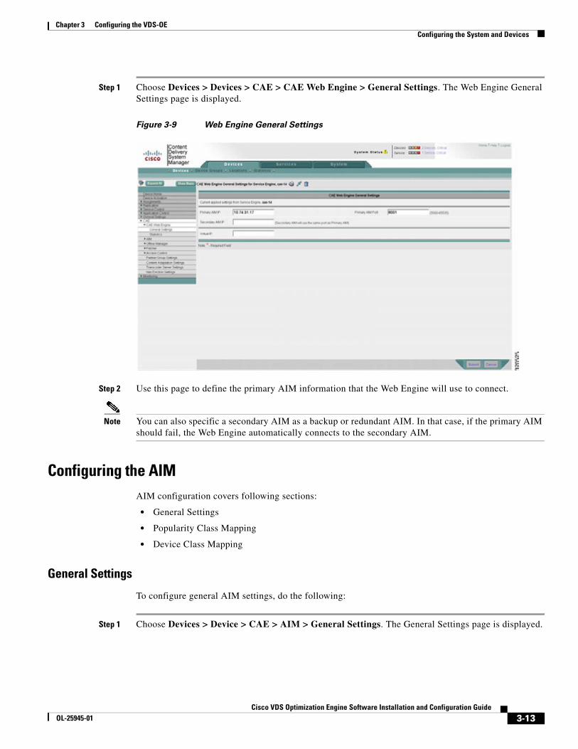
Step 1 Choose Devices > Devices > CAE > CAE Web Engine > General Settings. The Web Engine General Settings page is displayed.
Figure 3-9 Web Engine General Settings
Step 2 Use this page to define the primary AIM information that the Web Engine will use to connect.
Note You can also specific a secondary AIM as a backup or redundant AIM. In that case, if the primary AIM should fail, the Web Engine automatically connects to the secondary AIM.
Configuring the AIMAIM configuration covers following sections:
• General Settings
• Popularity Class Mapping
• Device Class Mapping
General Settings
To configure general AIM settings, do the following:
Step 1 Choose Devices > Device > CAE > AIM > General Settings. The General Settings page is displayed.

3-14Cisco VDS Optimization Engine Software Installation and Configuration Guide
OL-25945-01
Chapter 3 Configuring the VDS-OEConfiguring the System and Devices
Figure 3-10 AIM General Settings
Step 2 Define the AIM general settings, including:
• The TCP server port the AIM process should listen to. The TCP server port is for Web Engine and is set to 8001 by default.
• The Offline Manager to which the AIM should connect. If Offline Manager IP and Offline Manager Port are left blank, the AIM uses defaults to connect to Offline Manager.
3-15Cisco VDS Optimization Engine Software Installation and Configuration Guide
OL-25945-01
Chapter 3 Configuring the VDS-OEConfiguring the System and Devices
Popularity Class Mapping
To perform popularity class mapping, do the following:
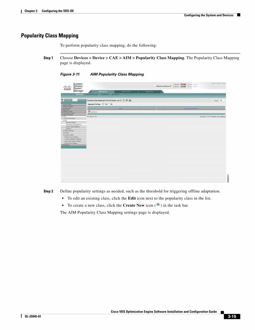
Step 1 Choose Devices > Device > CAE > AIM > Popularity Class Mapping. The Popularity Class Mapping page is displayed.
Figure 3-11 AIM Popularity Class Mapping
Step 2 Define popularity settings as needed, such as the threshold for triggering offline adaptation.
• To edit an existing class, click the Edit icon next to the popularity class in the list.
• To create a new class, click the Create New icon ( ) in the task bar.
The AIM Popularity Class Mapping settings page is displayed.
3-16Cisco VDS Optimization Engine Software Installation and Configuration Guide
OL-25945-01
Chapter 3 Configuring the VDS-OEConfiguring the System and Devices
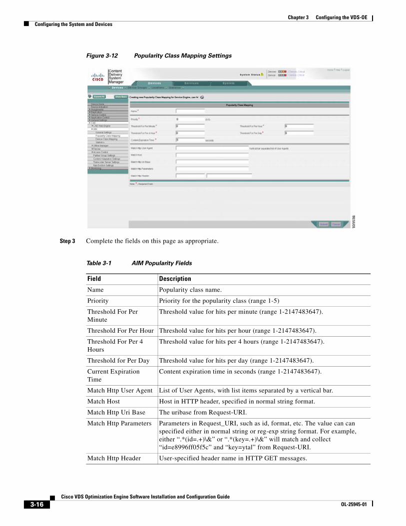
Figure 3-12 Popularity Class Mapping Settings
Step 3 Complete the fields on this page as appropriate.
Table 3-1 AIM Popularity Fields
Field Description
Name Popularity class name.
Priority Priority for the popularity class (range 1-5)
Threshold For Per Minute
Threshold value for hits per minute (range 1-2147483647).
Threshold For Per Hour Threshold value for hits per hour (range 1-2147483647).
Threshold For Per 4 Hours
Threshold value for hits per 4 hours (range 1-2147483647).
Threshold for Per Day Threshold value for hits per day (range 1-2147483647).
Current Expiration Time
Content expiration time in seconds (range 1-2147483647).
Match Http User Agent List of User Agents, with list items separated by a vertical bar.
Match Host Host in HTTP header, specified in normal string format.
Match Http Uri Base The uribase from Request-URI.
Match Http Parameters Parameters in Request_URI, such as id, format, etc. The value can can specified either in normal string or reg-exp string format. For example, either “.*(id=.+)\&” or “.*(key=.+)\&” will match and collect “id=e8996ff05f5c” and “key=ytal” from Request-URI.
Match Http Header User-specified header name in HTTP GET messages.

3-17Cisco VDS Optimization Engine Software Installation and Configuration Guide
OL-25945-01
Chapter 3 Configuring the VDS-OEConfiguring the System and Devices
Note Required fields are marked by an asterisk (*).
Device Class Mapping
To perform device class mapping, do the following:
Step 1 Choose Devices > Device > CAE > AIM > Device Class Mapping. The Device Class Mapping page is displayed.
Figure 3-13 AIM Device Class Mapping
Step 2 Use this page to define popularity settings, such as match rules for triggering adaptation or video selection.
3-18Cisco VDS Optimization Engine Software Installation and Configuration Guide
OL-25945-01
Chapter 3 Configuring the VDS-OEConfiguring the System and Devices
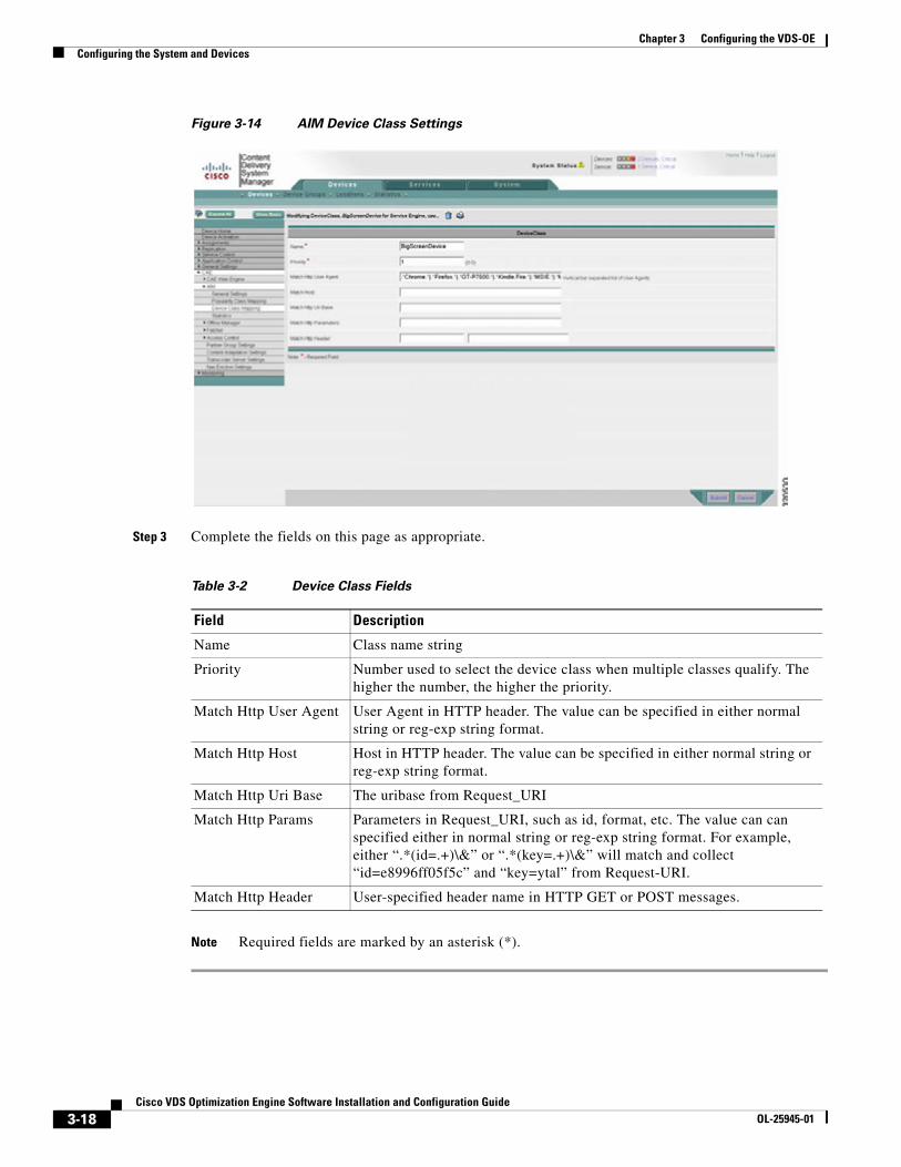
Figure 3-14 AIM Device Class Settings
Step 3 Complete the fields on this page as appropriate.
Note Required fields are marked by an asterisk (*).
Table 3-2 Device Class Fields
Field Description
Name Class name string
Priority Number used to select the device class when multiple classes qualify. The higher the number, the higher the priority.
Match Http User Agent User Agent in HTTP header. The value can be specified in either normal string or reg-exp string format.
Match Http Host Host in HTTP header. The value can be specified in either normal string or reg-exp string format.
Match Http Uri Base The uribase from Request_URI
Match Http Params Parameters in Request_URI, such as id, format, etc. The value can can specified either in normal string or reg-exp string format. For example, either “.*(id=.+)\&” or “.*(key=.+)\&” will match and collect “id=e8996ff05f5c” and “key=ytal” from Request-URI.
Match Http Header User-specified header name in HTTP GET or POST messages.

3-19Cisco VDS Optimization Engine Software Installation and Configuration Guide
OL-25945-01
Chapter 3 Configuring the VDS-OEConfiguring the System and Devices
Configuring the Offline ManagerThe OM is a process with external interfaces to AIM, Fetcher, and the CTM Server. The interfaces with AIM and Fetcher are Inter-Process Communication (IPC) messages that are exchanged over a TCP connection. The interface with CTM Server is made through an HTTP REST API, in which an XML message body is transported through the HTTP protocol.
The OM acts as both an HTTP client and an HTTP server. As an HTTP client, it submits HTTP POST transcoding job requests to the CTM Server. The CTM Server has an HTTP POST asynchronous job status notification mechanism that informs its application whether the submitted transcoding job was successfully performed. This requires that the OM act essentially as an HTTP server.
You can perform all OM configuration through the CDSM GUI or by using the CLI. The only exception is NAS configuration, which can only be performed through the CDSM GUI.
Note Where both CDSM and CLI methods exist for a procedure, they are equivalent and synchronized. For consistency, we recommend the use of the CDSM GUI if VDS-IS is also installed.
The following optional configurations are available for OM:
• General Settings
• Fetcher Settings
• Statistics (view only)
The following sections describe these procedures in detail.
Configuring OM General Settings
To configure OM general settings, do the following:
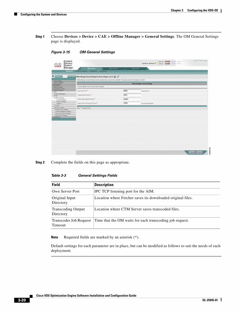
3-20Cisco VDS Optimization Engine Software Installation and Configuration Guide
OL-25945-01
Chapter 3 Configuring the VDS-OEConfiguring the System and Devices
Step 1 Choose Devices > Device > CAE > Offline Manager > General Settings. The OM General Settings page is displayed.
Figure 3-15 OM General Settings
Step 2 Complete the fields on this page as appropriate.
Note Required fields are marked by an asterisk (*).
Default settings for each parameter are in place, but can be modified as follows to suit the needs of each deployment.
Table 3-3 General Settings Fields
Field Description
Own Server Port IPC TCP listening port for the AIM.
Original Input Directory
Location where Fetcher saves its downloaded original files.
Transcoding Output Directory
Location where CTM Server saves transcoded files.
Transcoder Job Request Timeout
Time that the OM waits for each transcoding job request.
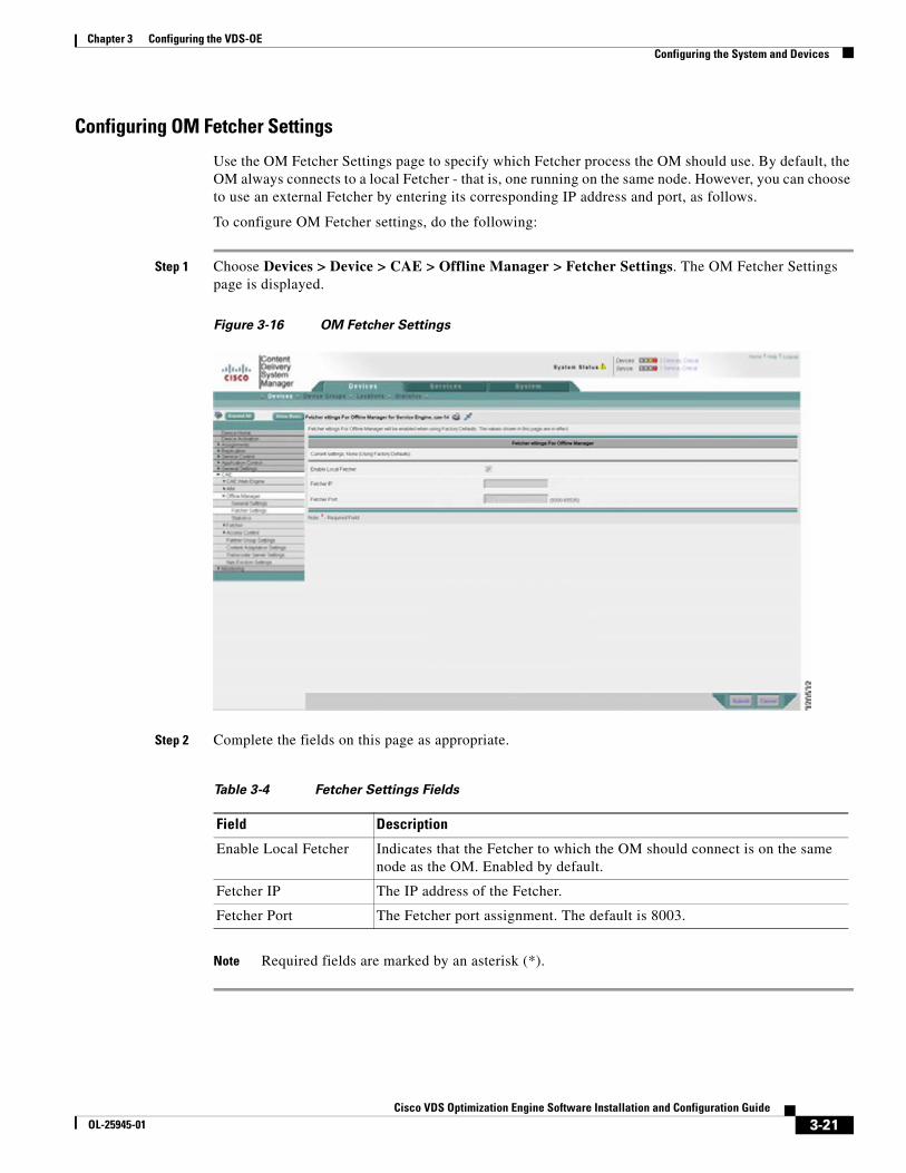
3-21Cisco VDS Optimization Engine Software Installation and Configuration Guide
OL-25945-01
Chapter 3 Configuring the VDS-OEConfiguring the System and Devices
Configuring OM Fetcher Settings
Use the OM Fetcher Settings page to specify which Fetcher process the OM should use. By default, the OM always connects to a local Fetcher - that is, one running on the same node. However, you can choose to use an external Fetcher by entering its corresponding IP address and port, as follows.
To configure OM Fetcher settings, do the following:
Step 1 Choose Devices > Device > CAE > Offline Manager > Fetcher Settings. The OM Fetcher Settings page is displayed.
Figure 3-16 OM Fetcher Settings
Step 2 Complete the fields on this page as appropriate.
Note Required fields are marked by an asterisk (*).
Table 3-4 Fetcher Settings Fields
Field Description
Enable Local Fetcher Indicates that the Fetcher to which the OM should connect is on the same node as the OM. Enabled by default.
Fetcher IP The IP address of the Fetcher.
Fetcher Port The Fetcher port assignment. The default is 8003.

3-22Cisco VDS Optimization Engine Software Installation and Configuration Guide
OL-25945-01
Chapter 3 Configuring the VDS-OEConfiguring the System and Devices
Reviewing OM Statistics
To review OM statistics, do the following:
Step 1 Choose Devices > Device > CAE > Offline Manager > Statistics. The OM Statistics page is displayed.
Figure 3-17 OM Statistics
Step 2 If needed, update the statistics display by clicking the Update Statistics ( ) button in the toolbar on this page.
Configuring the FetcherConfiguration of the Fetcher involves configuring general settings. This section describes the procedure in detail.

3-23Cisco VDS Optimization Engine Software Installation and Configuration Guide
OL-25945-01
Chapter 3 Configuring the VDS-OEConfiguring the System and Devices
General Settings
To configure general Fetcher settings, do the following:
Step 1 Choose Devices > Devices > CAE > Fetcher > General Settings. The Fetcher General Settings page is displayed.
Figure 3-18 Fetcher General Settings
Step 2 Complete the fields on this page as appropriate.
Note Required fields are marked by an asterisk (*).
Configuring Access ControlThe AIM component manages a Blacklist and a Whitelist that can be used to identify content to be transcoded. The Blacklist identifies content that is not to be transcoded, while the Whitelist identifies content that is to be transcoded. The two lists can be referenced independently.
Table 3-5 Fetcher General Settings Fields
Field Description
Fetcher Server Port The port the Fetcher uses to listen to requests from the OM. The default is 8003.
Content Fetch Timeout The timeout for content fetch in seconds. The default is 1800.

3-24Cisco VDS Optimization Engine Software Installation and Configuration Guide
OL-25945-01
Chapter 3 Configuring the VDS-OEConfiguring the System and Devices
When either list is used, the AIM compares the Host, Referrer, Client IP, and User Agent strings in the incoming HTTP request (CRREQ) header, along with corresponding entries in other generic HTTP headers, first in the Blacklist (if used) and then in the Whitelist (if used). Appropriate action is then taken as follows:
• If the Blacklist is not configured or has no match for the HTTP message header, the header is passed to the Whitelist for comparison.
• If the Blacklist is configured and a match is found, the video request is bypassed, and the HTTP message header is not passed to the Whitelist.
• If the Whitelist is not configured or if a match is found in the Whitelist for the HTTP message header, transcoding is performed, and the choice of offline or online transcoding is made based on the information in the adaptation XML file.
• If the Whitelist is configured and no match is found, the video request is bypassed.
Note Blacklist and Whitelist configurations are processed only by the OFAM, so only the OFAM server requires Blacklist and Whitelist configurations. The decisions derived from this processing are passed to other system components as appropriate.
Configuring Partner Group SettingsYou can add a partner group to the configuration as follows:
Step 1 Choose Devices > Devices > CAE > Partner Group Settings. The Partner Group Settings page is displayed.
Figure 3-19 Partner Group Settings
Step 2 In the Name field, enter a name for the partner group.

3-25Cisco VDS Optimization Engine Software Installation and Configuration Guide
OL-25945-01
Chapter 3 Configuring the VDS-OEConfiguring the System and Devices
Step 3 Click to select items from the Partner list to add to the group.
Step 4 Click Add Partner to add the selected partners to the group.
Step 5 Click Submit to save your entries, or click Cancel to abort the operation.
Note To delete partners from the group, select the partners to be deleted and click Delete Selected Partners.
Configuring 3GP and 3G2 SettingsThe factory default XML file is preconfigured to enable 3GP and 3G2 caching. The following pattern matching rules and actions apply:
<PatternListGrp id="3GP"> <ContentSourceType>3gp</ContentSourceType> </PatternListGrp>
<PatternListGrp id="3G2"> <ContentSourceType>3g2</ContentSourceType> </PatternListGrp>
These pattern rules will match the following actions respectively
<SetParameter matchGroup="3GP"> <Action>Cache_Only</Action> </SetParameter>
<SetParameter matchGroup="3G2"> <Action>Cache_Only</Action> </SetParameter>
The action Cache_Only is defined as follows:
<Rule_SetAction name="Cache_Only"> <SetParameter name="Progressive-Video"> <CacheOnly>1</CacheOnly> </SetParameter>
Cache-only action is enabled or disabled by setting or resetting the <CacheOnly> tag. A 1 indicates that Cache_Only is enabled.
AIM Popularity for 3GP and 3G2 Video
The AIM popularity threshold configuration is also used as a trigger for 3GP and 3G2 video caching, and the OE uses the same ordering rules for serving popular content. The first access of a 3GP or 3G2 video available for offline serving is served to the client from the NAS. At the same time, the SE caches the video to its local cache, and any subsequent requests are then served from the SE’s local cache.

3-26Cisco VDS Optimization Engine Software Installation and Configuration Guide
OL-25945-01
Chapter 3 Configuring the VDS-OEConfiguring the System and Devices
Registering the Content Adaptation File (Optional)The OFAM requires a Content Adaptation File to determine what action to take with regard to original video files downloaded by the Fetcher. The Content Adaptation File may include instructions for transcoding progressive video, applying pacing to a video stream, and modifying the HLS manifest file – for example, to delete an unwanted bit rate from the manifest file and insert a new bit rate with specific use conditions.
The first step in Content Adaptation File registration is to create an XML configuration file using a suitable text editor. After creating the XML file, you upload the file to the CDSM and then download the file to the SEs.
Note A sample Content Adaptation File is provided in the form of the factory default adaptation XML file, factory.xml. You cannot modify or delete this file, but you can add additional XML files. The device configuration determines which adaptation file is currently in effect.
To register a content adaptation file, do the following:
Step 1 Create the Content Adaptation File according to the factory default adaptation XML file provided as an example.
Step 2 Choose System > Configuration > Content Adaptation File Registration > Create (click the file icon) to create the Content Adaptation XML file. The File Registration page is displayed.
Step 3 In the File Registration page, choose Import or Upload as appropriate to transmit the Content Adaptation Configuration File to the CDSM.
Figure 3-20 Content Adaptation File Registration Page
Step 4 Choose Devices > CAE > Content Adaptation Settings. The Content Management Settings page is displayed.

3-27Cisco VDS Optimization Engine Software Installation and Configuration Guide
OL-25945-01
Chapter 3 Configuring the VDS-OEConfiguring the System and Devices
Step 5 Select the XML file to be downloaded to the SEs (factory.xml in the example shown below), then click Submit in the lower right corner of the page. CDSM downloads the XML file to the SEs.
Figure 3-21 Content Adaptation File Registration – Submit File
Registering the NAS File
The NAS acts both as a centralized storage device and as an HTTP origin server (Web server) for the OE. As a storage device, the OM instructs the Fetcher process to save original content downloaded from an external Web server to a specified directory on the NAS. Similarly, the Offline Manager selects a NAS directory and filename for the Transcoder Server to store the transcoded content.
Because the OM is aware of the NAS info, it can generate a NAS-based HTTP URL for accessing the transcoded content. This URL is later saved to the AIM database.
Note Both the the IP address and the domain name are supported for NAS mounting.
As mentioned earlier, you can only configure the NAS through the CDSM. You must first prepare a NAS XML configuration file. For example, a file named “nas_mount.xml” can contain:
<?xml version="1.0" ?> <CdsOrigin> <server name="CAE-nas" host="172.25.128.122" /> <sourceNFS name="NFS" sharePoint="vol/vol0/home" access="rw" rsize="32768" maxRetry="10"
/> <localMount name="local" source="NFS" mountPoint="cae" order="fcfs" num-of-mounts="1"
serverList="CAE-nas" /> </CdsOrigin>
After creating the XML file, you can upload the file to the CDSM as follows:
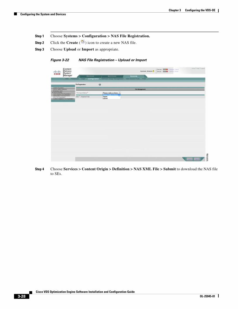
3-28Cisco VDS Optimization Engine Software Installation and Configuration Guide
OL-25945-01
Chapter 3 Configuring the VDS-OEConfiguring the System and Devices
Step 1 Choose Systems > Configuration > NAS File Registration.
Step 2 Click the Create ( ) icon to create a new NAS file.
Step 3 Choose Upload or Import as appropriate.
Figure 3-22 NAS File Registration – Upload or Import
Step 4 Choose Services > Content Origin > Definition > NAS XML File > Submit to download the NAS file to SEs.

3-29Cisco VDS Optimization Engine Software Installation and Configuration Guide
OL-25945-01
Chapter 3 Configuring the VDS-OEConfiguring the System and Devices
Figure 3-23 NAS File Registration – Download to SEs
Creating a Delivery Service and Location
For instructions on creating a delivery service and location, see the Cisco Internet Streamer CDS 2.6 Software Configuration Guide (OL-23609).
Configuring the Transcoder ServerTranscoder Server configuration is required for both the SE and OFAM components of the OE. Perform the following steps to configure the Transcoder Server IP address and port assignment and add related information as needed.
Tip Obtain the IP address of the Transcoder Server before performing this procedure, as it will be needed to complete the procedure. The default Transcoder port is 8062.
Note The IP address and port assignment for the Transcoder Server are mandatory.
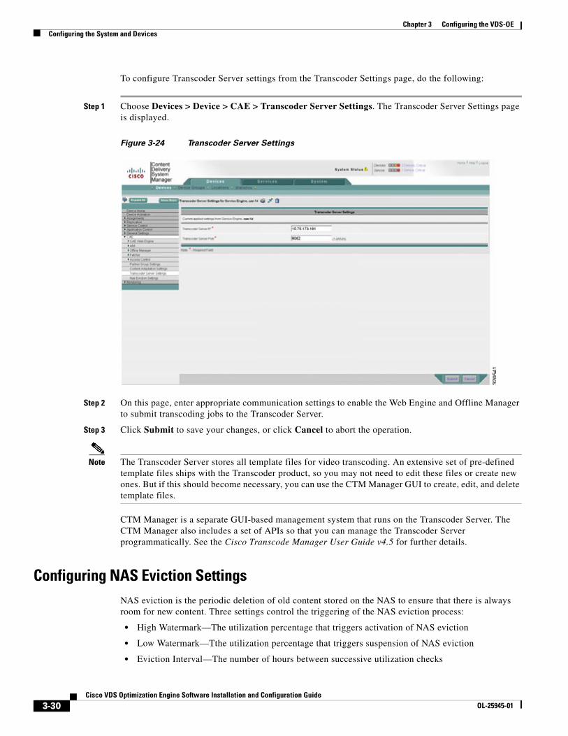
3-30Cisco VDS Optimization Engine Software Installation and Configuration Guide
OL-25945-01
Chapter 3 Configuring the VDS-OEConfiguring the System and Devices
To configure Transcoder Server settings from the Transcoder Settings page, do the following:
Step 1 Choose Devices > Device > CAE > Transcoder Server Settings. The Transcoder Server Settings page is displayed.
Figure 3-24 Transcoder Server Settings
Step 2 On this page, enter appropriate communication settings to enable the Web Engine and Offline Manager to submit transcoding jobs to the Transcoder Server.
Step 3 Click Submit to save your changes, or click Cancel to abort the operation.
Note The Transcoder Server stores all template files for video transcoding. An extensive set of pre-defined template files ships with the Transcoder product, so you may not need to edit these files or create new ones. But if this should become necessary, you can use the CTM Manager GUI to create, edit, and delete template files.
CTM Manager is a separate GUI-based management system that runs on the Transcoder Server. The CTM Manager also includes a set of APIs so that you can manage the Transcoder Server programmatically. See the Cisco Transcode Manager User Guide v4.5 for further details.
Configuring NAS Eviction SettingsNAS eviction is the periodic deletion of old content stored on the NAS to ensure that there is always room for new content. Three settings control the triggering of the NAS eviction process:
• High Watermark—The utilization percentage that triggers activation of NAS eviction
• Low Watermark—Tthe utilization percentage that triggers suspension of NAS eviction
• Eviction Interval—The number of hours between successive utilization checks

3-31Cisco VDS Optimization Engine Software Installation and Configuration Guide
OL-25945-01
Chapter 3 Configuring the VDS-OEConfiguring the System and Devices
By default, NAS utilization is checked at Eviction Intervals of 2 hours. Then, NAS eviction is activated if the NAS has reached or exceeded a High Watermark of 75% utilization, or suspended if the NAS has reached or fallen below a Low Watermark of 65% utilization.
These settings can be modified to suit the needs of different deployments as follows:
Step 1 Navigate to Devices > Device > CAE > NAS Eviction Settings. The NAS Eviction Settings page is displayed.
Figure 3-25 NAS Eviction Settings Page
Step 2 Enter new values for High Watermark, Low Watermark, and Eviction Interval as needed.
Step 3 Click Submit to save your changes, or click Cancel to abort the operation.
Configuring Transaction LoggingThe Transaction Logging feature records a log of significant system events, including a record of each video served, and saves it to the CAE-SE file system. You use the Transaction Log Settings page to enable Transaction Logging and define appropriate settings for your deployment.
The following settings are available on the Transaction Log Settings page:
• Transaction Log Enable—Check to enable or clear to disable
• Log Windows Domain—Check to enable or clear to disable
• Enable Export—Check to enable or clear to disable
• Export occurs—Define the interval for Transaction Log export
• FRP Export Server—Name, credentials, and location for each export server

3-32Cisco VDS Optimization Engine Software Installation and Configuration Guide
OL-25945-01
Chapter 3 Configuring the VDS-OEConfiguring the System and Devices
• Enable Windows Media Settings—Check to enable or clear to disable
• Log File Format—wms-41
To access the Transaction Log Settings page, do the following:
Step 1 Navigate to Devices > Device > Service Control > Transaction Logging. The Transaction Log Settings page is displayed.
Figure 3-26 Transaction Log Settings Page
Step 2 Update the fields on this page as needed to configure Transaction Logging for your deployment.
Step 3 Click Submit to save your changes, or click Cancel to abort the operation.

C H A P T E R
4-1Cisco VDS Optimization Engine Software Installation and Configuration Guide
OL-25945-01
4Managing and Monitoring the VDS-OE
OverviewThis chapter describes the functions available in the CDSM and elsewhere for managing and monitoring the OE and related operations.
ManagementThe CDSM can be used to manage the OE as well as VDS-IS, if also installed. The CDSM features a GUI interface and a synchronized command line interface (CLI) for browser-based or command-line driven network management and device monitoring.
The OE can also be managed using an XML or CLI/API interface. Existing UCS platform APIs can be adopted for platform specific management.
NAS ManagementThe NAS is managed by the CdsOrigMgr process. The process mounts the NAS at a proper share point, periodically (every 5 seconds) monitors the NAS accessibility, and writes an /etc/nasinfo file. The Offline Manager reads the /etc/nasinfo file to gather the NAS related information. The NAS is mounted as read-only. For OE, however, the NAS must be mounted as read-write. Dynamic NAS mount changes are supported by the Offline Manager.
The Offline Manager uses a specific convention to organize the original (input) and transcoded (output) files.
Input Location
By default, input files are placed in the following location:
$NAS_share_dir/$input_dir/$YYYY_MM_DD/$SE_hostname/$device_class/$url_domain/$asset_descriptor.$container_type
For example:
/state/export/NAS/172.25.128.122/cae/0/input/2012_04_08/sjst68/iPad/172.25.128.81/ ab8f76df002012031200323500e228e1.flv
Where:
4-2Cisco VDS Optimization Engine Software Installation and Configuration Guide
OL-25945-01
Chapter 4 Managing and Monitoring the VDS-OEManagement
• $NAS_share_dir – “/state/export/NAS/172.25.128.122/cae/0/”. This portion is configurable based on the NAS XML mounting file.
• $input_dir – “input”; This portion is configurable using either CLI or CDSM.
• $YYYY_MM_DD – “2012_04_08”
• $SE_hostname – “sjst68”
• $device_class – “iPad”
• $url_domain – “172.25.128.81”
• $asset_descriptor – “ab8f76df002012031200323500e228e1”
• $container_type – “flv”
Note For HLS ABR, only the master(parent) manifest file is named using the $asset_descriptor.m3u8. Its associated chunk (.ts) files are placed in a subfolder of the parent manifest file folder.
Output Location
By default, output files are placed in the following location:
$NAS_share_dir/$output_dir/$YYYY_MM_DD/$SE_hostname/$url_domain/$path/$asset_descriptor+$device_class+$Adapatation_Profile_index.$container_type
For example:
/state/export/NAS/172.25.128.122/cae/0/output/2012_04_05/p-cae/sjst81.cisco.com/sample /6d2f80bc00201109081355020052162f+iPhone4+0.mp4
Where:
• $NAS_share_dir – “/state/export/NAS/172.25.128.122/cae/0/”. This portion is configurable based on the CdsOrigMgr NAS XML mounting file.
• $output_dir – “output”; This portion is configurable using either CLI or CDSM.
• $YYYY_MM_DD – “2012_04_05”
• $SE_hostname – “p-cae”
• $url_domain – “sjst81.cisco.com”
• $path – “sample”
• $asset_descriptor – “6d2f80bc00201109081355020052162f”
• $device_class – “iPhone4”
• $Adaptation_Profile_Index– “0”
• $container_type – “mp4”
Similarly, only the master (parent) manifest file is named using the above scheme for HLS ABR. The files for newly created ABR rate are named as follows:
• $new_rate_dir – “hls_rate_150000”, where 150000 indicates its corresponding bit rate. This rate directory is located is the same directory as the parent manifest file.
• The child manifest file and its corresponding transcoded chunk (.ts) files are placed in the $new_rate_dir.

4-3Cisco VDS Optimization Engine Software Installation and Configuration Guide
OL-25945-01
Chapter 4 Managing and Monitoring the VDS-OEManagement
NAS Eviction
Both original and transcoded files are saved to NAS. The goal of NAS eviction is to ensure that there is always room on the NAS for new input or output files. When multiple OFAMs are deployed in the network, each OFAM performs its NAS eviction independently without causing conflict with others. This is because each OFAM only evicts the entries or files that it creates.
For HLS ABR, eviction is applied both to the parent manifest and to its child manifest and its chunk (.ts) files.
Input Files
In theory, input files are no longer needed after transcoding is completed, and so could be deleted immediately. However, it is sometimes helpful as a debugging aid to retain input files for a fixed time period after transcoding. Accordingly, input files and their associated directories are kept for up to two days before being evicted.
Note When NAS eviction occurs, the corresponding alarms are generated and then canceled.
Output Files
Eviction (deletion) of output files is efficiently managed by the AIM process because the AIM normally has a database entry for each transcoded asset. When multiple AIMs are deployed in an OE solution, each AIM should only evict the files (database entries) that are created by the same host. The creating hostname is embedded in the NAS directory. An empty NAS directory is deleted as it no longer contains any files.
Note NAS eviction works independently of AIM redundancy.
The AIM employs several mechanisms to decide to delete an output file:
Content Expiry
When a transcoded video file expires and is detected by the AIM as it scans through its database entries, the AIM deletes the database entry and its corresponding NAS file(s).
Triggers
Different mechanisms can trigger the eviction process. For example:
• The AIM periodically wakes up to check whether NAS utilization has reached a configured high watermark (default to 75%).
• Eviction is suspended once the low watermark of NAS utilization (default to 65%) is achieved.
Algorithm
The eviction algorithm is driven by the following parameters:
• Last Access Time. The AIM database tracks the Last Access Time for each asset and deletes the database entry and its NAS file starting with those with the oldest last access time.
Note This field is synchronized among the AIMs if redundancy is enabled.

4-4Cisco VDS Optimization Engine Software Installation and Configuration Guide
OL-25945-01
Chapter 4 Managing and Monitoring the VDS-OEMonitoring
• Dangling NAS Files. A dangling NAS file is one that no longer has a corresponding AIM database entry. Dangling NAS files can be deleted at any time. To save resources, the AIM scans from the oldest directory forward to find dangling NAS files. Due to the distributed nature of the OE solution, it is possible for AIMs to delete too many files during NAS eviction. This requires the AIM to verify the low watermark after each small batch of files is deleted and stop eviction immediately once the low watermark is reached.
• Two Phase Deletion. In a distributed cluster, there is a delay for the database to synchronize among its nodes. To account for this, files to be deleted are marked for deletion in the first phase, or scan. The database entries and corresponding NAS files will be removed at a later AIM scan time.
Monitoring
KPI ReportingThe OE reports key performance indicators (KPIs) for its own features through the CDSM. The OE also reports KPIs on behalf of the CTM.
The OE and the CTM encoders generate reports indicating CPU loading, time taken to process content types, efficiencies gained by using the various techniques, average hold times for transformed content, storage status, and related parameters.
The OE is able to collect reports per website, per MVG, per VDS ingest point from the perspective of the OE, Per Device Class Transformation, Per Profile, Per Codec Type, and Per Container Type.
KPI reporting is configurable for the counters and the time interval, and supports the transfer of bulk statistics file to the CDSM via SFTP, FTP, or other required means. CTM encoders also report their KPIs through the OE.
Statistics ReportingThe CMS agent that resides on the device periodically collects statistics from the AIM, Web Engine, and other related processes, and sends these data to the CDSM. The user can request a statistics update by clicking Update Statistics on the CDSM toolbar. If the OE is disabled or if the process is not running, the value of statistical items will be N/A in the GUI page.
The OE provides a history of statistics per month, week, day, hour, and minute, including interaction logs with CDS, MVG, and the device database. This information helps operators predict the need for capacity expansion and provides them with advance notice of potential OE overload events.
The OE supports the generation of bulk statistics file in a specified format, which is currently used by the CDSM.
Note Clients that generate multiple range requests for a single video with different URLs will cause the popularity count for the video to be incremented multiple times, thereby inflating the popularity statistics for the video asset.

4-5Cisco VDS Optimization Engine Software Installation and Configuration Guide
OL-25945-01
Chapter 4 Managing and Monitoring the VDS-OEMonitoring
OFAM Statistics
Following is a complete sample list of statistics that the OFAM displays in response to the show cae offline-mgr statistics CLI command.
OFAM#show cae offline-mgr statistics
Offline-Mgr Progressive Statistics CAREQ Requests Recv : 5 CAIND Response Sent : 5 CANOT Response Sent : 0 Fetch Requests Sent : 5 Fetch Response Recv : 5 Transcode Job Requests : 4 Transcode Job Response : 4 CAREQ Requests Recv failed : 0 CAIND Response Sent failed : 0 CANOT Response Sent failed : 0 Fetch Requests Sent failed : 0 Fetch Response Recv failed : 0 Cache-only success : 1 Cache-only failed : 0 Transcode Job Requests failed : 0 Transcode Job Response failed : 0
Offline-Mgr HLS ABR Statistics Manifest CAREQ Requests Recv : 0 Manifest CAIND Response Sent : 0 Manifest CANOT Response Sent : 0 Manifest Fetch Requests Sent : 0 Manifest Fetch Response Recv : 0 Chunk Fetch Requests Sent : 0 Chunk Fetch Response Recv : 0 Chunk Transcode Job Requests : 0 Chunk Transcode Job Response : 0 Manifest CAREQ Requests Recv failed : 0 Manifest CAIND Response Sent failed : 0 Manifest CANOT Response Sent failed : 0 Manifest Fetch Requests Sent failed : 0 Manifest Fetch Response Recv failed : 0 Chunk Fetch Requests Sent failed : 0 Chunk Fetch Response Recv failed : 0 Chunk Transcode Job Requests failed : 0 Chunk Transcode Job Response failed : 0
SE Statistics
Following is a complete sample list of statistics that the SE displays in response to the show stat web-engine CLI command.
SE#show stat web-engine
HTTP Request Info Statistics-----------------------Num Lookups : 2 Preposition Hit : 0 External Hit : 1 Cache Hit : 1 Cache Miss : 0 Partial Cache Hit : 0 Cache Bypass : 0
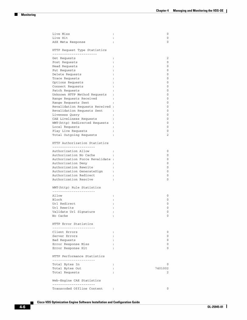
4-6Cisco VDS Optimization Engine Software Installation and Configuration Guide
OL-25945-01
Chapter 4 Managing and Monitoring the VDS-OEMonitoring
Live Miss : 0 Live Hit : 0 ASX Meta Response : 0
HTTP Request Type Statistics-----------------------Get Requests : 2 Post Requests : 0 Head Requests : 0 Put Requests : 0 Delete Requests : 0 Trace Requests : 0 Options Requests : 0 Connect Requests : 0 Patch Requests : 0 Unknown HTTP Method Requests : 0 Range Requests Received : 0 Range Requests Sent : 0 Revalidation Requests Received : 0 Revalidation Requests Sent : 0 Liveness Query : 0 CAE Liveliness Requests : 0 WMT(http) Redirected Requests : 0 Local Requests : 0 Play Live Requests : 0 Total Outgoing Requests : 2
HTTP Authorization Statistics----------------------Authorization Allow : 0 Authorization No Cache : 0 Authorization Force Revalidate : 0 Authorization Deny : 0 Authorization Rewrite : 0 Authorization GenerateSign : 0 Authorization Redirect : 0 Authorization Resolve : 0
WMT(http) Rule Statistics----------------------Allow : 0 Block : 0 Url Redirect : 0 Url Rewrite : 0 Validate Url Signature : 0 No Cache : 0
HTTP Error Statistics----------------------Client Errors : 0 Server Errors : 0 Bad Requests : 0 Error Response Miss : 0 Error Response Hit : 0
HTTP Performance Statistics----------------------Total Bytes In : 0 Total Bytes Out : 7401002 Total Requests : 2
Web-Engine CAE Statistics----------------------Transcoded Offline Content : 0
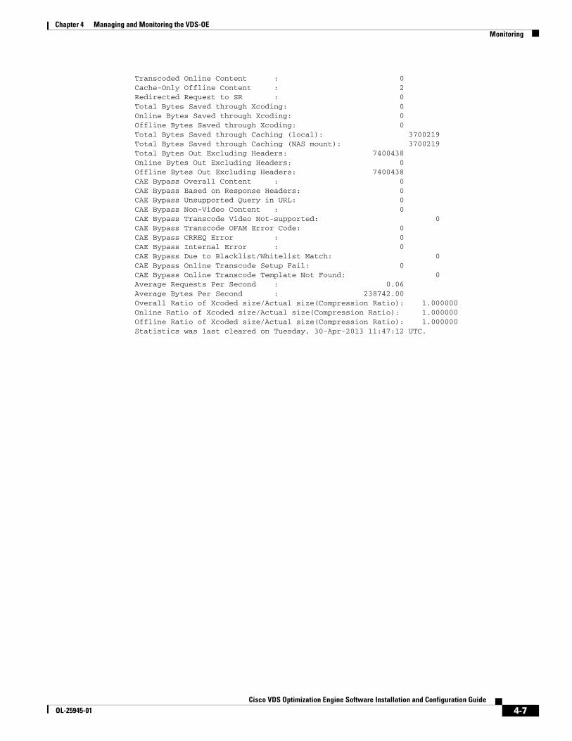
4-7Cisco VDS Optimization Engine Software Installation and Configuration Guide
OL-25945-01
Chapter 4 Managing and Monitoring the VDS-OEMonitoring
Transcoded Online Content : 0 Cache-Only Offline Content : 2 Redirected Request to SR : 0 Total Bytes Saved through Xcoding: 0 Online Bytes Saved through Xcoding: 0 Offline Bytes Saved through Xcoding: 0 Total Bytes Saved through Caching (local): 3700219 Total Bytes Saved through Caching (NAS mount): 3700219 Total Bytes Out Excluding Headers: 7400438 Online Bytes Out Excluding Headers: 0 Offline Bytes Out Excluding Headers: 7400438 CAE Bypass Overall Content : 0 CAE Bypass Based on Response Headers: 0 CAE Bypass Unsupported Query in URL: 0 CAE Bypass Non-Video Content : 0 CAE Bypass Transcode Video Not-supported: 0 CAE Bypass Transcode OFAM Error Code: 0 CAE Bypass CRREQ Error : 0 CAE Bypass Internal Error : 0 CAE Bypass Due to Blacklist/Whitelist Match: 0 CAE Bypass Online Transcode Setup Fail: 0 CAE Bypass Online Transcode Template Not Found: 0 Average Requests Per Second : 0.06 Average Bytes Per Second : 238742.00 Overall Ratio of Xcoded size/Actual size(Compression Ratio): 1.000000 Online Ratio of Xcoded size/Actual size(Compression Ratio): 1.000000 Offline Ratio of Xcoded size/Actual size(Compression Ratio): 1.000000 Statistics was last cleared on Tuesday, 30-Apr-2013 11:47:12 UTC.
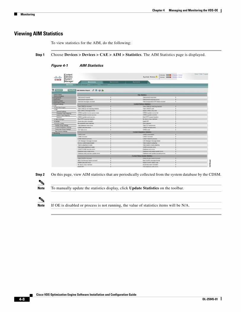
4-8Cisco VDS Optimization Engine Software Installation and Configuration Guide
OL-25945-01
Chapter 4 Managing and Monitoring the VDS-OEMonitoring
Viewing AIM Statistics
To view statistics for the AIM, do the following:
Step 1 Choose Devices > Devices > CAE > AIM > Statistics. The AIM Statistics page is displayed.
Figure 4-1 AIM Statistics
Step 2 On this page, view AIM statistics that are periodically collected from the system database by the CDSM.
Note To manually update the statistics display, click Update Statistics on the toolbar.
Note If OE is disabled or process is not running, the value of statistics items will be N/A.

4-9Cisco VDS Optimization Engine Software Installation and Configuration Guide
OL-25945-01
Chapter 4 Managing and Monitoring the VDS-OEMonitoring
Viewing Offline Manager Statistics
To view statistics for the OM, do the following:
Step 1 Choose Devices > Devices > CAE > Offline Manager > Statistics. The Offline Manager Statistics page is displayed.
Figure 4-2 Offline Manager Statistics
Step 2 On this page, view OM statistics periodicaly collected by the CDSM from the system database.
Note You can manually update the statistics display by clicking Update Statistics on the toolbar.
Note If the OE is disabled or if the process is not running, the value of statistics items will be N/A.
Statistics for 3GP and 3G2 Video
Two OFAM counters, Cache-only Success and Cache-only Fail, indicate how many 3GP and 3G2 videos crossed the popularity threshold and attempted cache-only optimization. The Success counter indicates how many were successfully cached, while the Failed counter indicates how many failed. The sum of these two counters indicates how many videos attempted local caching.
ExampleOFAM#show cae offline-mgr statistics. . .Offline-Mgr Progressive Statistics---------------------- . . . Cache-only success : 10 Cache-only failed : 0 . . .
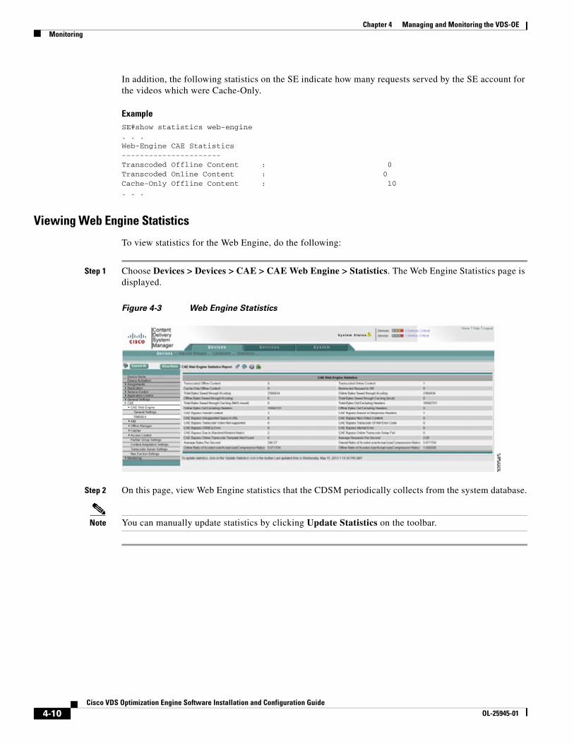
4-10Cisco VDS Optimization Engine Software Installation and Configuration Guide
OL-25945-01
Chapter 4 Managing and Monitoring the VDS-OEMonitoring
In addition, the following statistics on the SE indicate how many requests served by the SE account for the videos which were Cache-Only.
ExampleSE#show statistics web-engine . . .Web-Engine CAE Statistics----------------------Transcoded Offline Content : 0 Transcoded Online Content : 0 Cache-Only Offline Content : 10. . .
Viewing Web Engine Statistics
To view statistics for the Web Engine, do the following:
Step 1 Choose Devices > Devices > CAE > CAE Web Engine > Statistics. The Web Engine Statistics page is displayed.
Figure 4-3 Web Engine Statistics
Step 2 On this page, view Web Engine statistics that the CDSM periodically collects from the system database.
Note You can manually update statistics by clicking Update Statistics on the toolbar.
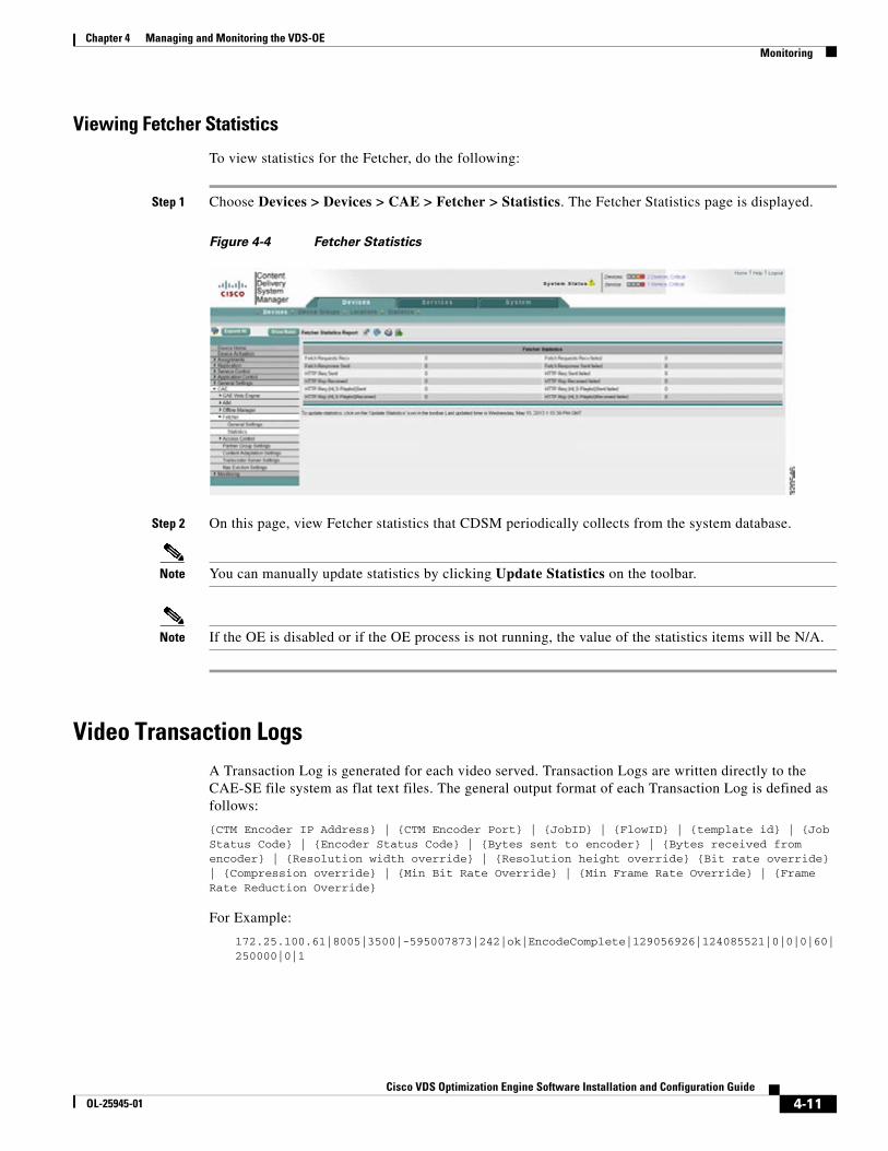
4-11Cisco VDS Optimization Engine Software Installation and Configuration Guide
OL-25945-01
Chapter 4 Managing and Monitoring the VDS-OEMonitoring
Viewing Fetcher Statistics
To view statistics for the Fetcher, do the following:
Step 1 Choose Devices > Devices > CAE > Fetcher > Statistics. The Fetcher Statistics page is displayed.
Figure 4-4 Fetcher Statistics
Step 2 On this page, view Fetcher statistics that CDSM periodically collects from the system database.
Note You can manually update statistics by clicking Update Statistics on the toolbar.
Note If the OE is disabled or if the OE process is not running, the value of the statistics items will be N/A.
Video Transaction LogsA Transaction Log is generated for each video served. Transaction Logs are written directly to the CAE-SE file system as flat text files. The general output format of each Transaction Log is defined as follows:
{CTM Encoder IP Address} | {CTM Encoder Port} | {JobID} | {FlowID} | {template id} | {Job Status Code} | {Encoder Status Code} | {Bytes sent to encoder} | {Bytes received from encoder} | {Resolution width override} | {Resolution height override} {Bit rate override} | {Compression override} | {Min Bit Rate Override} | {Min Frame Rate Override} | {Frame Rate Reduction Override}
For Example:
172.25.100.61|8005|3500|-595007873|242|ok|EncodeComplete|129056926|124085521|0|0|0|60|250000|0|1

4-12Cisco VDS Optimization Engine Software Installation and Configuration Guide
OL-25945-01
Chapter 4 Managing and Monitoring the VDS-OEMonitoring
Custom Transaction Log Tokens
The following table describes the tokens that are used to define the format of custom OE transaction logs. The tokens listed first in the table are taken from VDS-IS. Later tokens with the prefix [CAE] are specific to the OE.
Table 4-1 Transaction Log Tokens
Token Description
%a IP address of the requesting client
%A P address of the CAE-SE
%b Bytes sent, excluding HTTP headers
%C ThinkTimes – Time to Auth | Time to Lookup | Time to Route | Time to OS ? (ms)
%D Time consumed to serve the request in microseconds
%h Remote host (IP address of the requesting client is logged)
%H Request protocol
%I Bytes received from the client
%g Storage URL
%G Source URL
%m Request method
%O Bytes sent to client, including the headers
%q Query string (which is preceded by a question mark (?) if a query string exists; otherwise, it is an empty string)
%r First line of the request
%Z Request receive time (formatted)
%>s Status; the transaction log code always returns the HTTP response code for the request
%t Time in common log time format (or standard English format)
%T Time consumed to serve the request in seconds (a floating point number with 3 decimal places)
%u URL path requested, including query strings
%U URL path requested, not including query strings
%V Value of the host request header field reported if the host appeared in the request. If the host did not appear in the host request header, the IP address of the server specified in the URL is reported.
%X Connection status when the response is completed
%M Mime Type
%L Asset Size
%I Bytes Requested + Response Header Length
%J NetworkXferAvgRtt | NetworkXferMaxRtt
%K NetworkXferCwndFlicker
%N NetworkXferIfName
%{<header_name>}i HTTP Header as specified by header name; can be standard or non-standard headers; one entry for each header. For example, %{User-Agent }i.
4-13Cisco VDS Optimization Engine Software Installation and Configuration Guide
OL-25945-01
Chapter 4 Managing and Monitoring the VDS-OEMonitoring
%[CAE]s Client Serving Type and (optional) Bypass Reason.
Possible values for Client Serving Type:
OFFLINE_XCODED_NAS_MOUNT
OFFLINE_XCODED_NAS_HTTP
OFFLINE_XCODED_LOCAL_CACHE
ONLINE_XCODED
ONLINE_VIDEO_BYPASS
ONLINE_NONVIDEO_BYPASS
OFFLINE_SR_REDIRECT
ONLINE_ABR_PARENT_MANIFEST
ONLINE_ABR_CHILD_MANIFEST
OFFLINE_ABR_CHILD_MANIFEST
Possible values for Bypass Reason:
ExistDataSourceNotFoundFor RangeRequest
UnsupportedMediaFormat
UnknownMediaFormat
MetaDataAbsertForH264FLV
UnsupportedURLParameters
ResponseHeaderNotOK
TranscodeNotSupported
NonVideoContent
FailedToPostJobToArmada
UnableToFindTemplate
ErrorReceivedFromOFAM
Unknown
%[CAE]t Bytes saved due to transcoding; that is, the difference between the bytes that would have been served to the client and the actual bytes served
%[CAE]x Compression ratio (bytes actually served to client) / (bytes that would be served from OS). This is for both online or offline transcoding
%[CAE]c Bytes saved due to caching; that is, the bytes that would have been retrieved directly from the OS if not for caching; either local or NAS
%[CAE]d Device Class
%[CAE]p Popularity Class
%[CAE]a Asset Descriptor
%[CAE]i API (Adaptation Profile Index)
%[CAE]o Online Transcoding Attributes
%[CAE]b Bit-rate Indication
Token Description
4-14Cisco VDS Optimization Engine Software Installation and Configuration Guide
OL-25945-01
Chapter 4 Managing and Monitoring the VDS-OEMonitoring
The following is an example of a custom Transaction Log format using these tokens.
transaction-logs format custom "%U %O %b %I %m %>s %R %H %{User-Agent}i %{Host}i %{X-adaptation-profile-index}i %{X-forwarded-dest-addr-port}i %{Range}i %{Last-Modified}o %{Content-Type}o %{ETag}o %[CAE]x %[CAE]d %[CAE]p %[CAE]i %[CAE]t %[CAE]s %[CAE]c %[CAE]a %[CAE]o"
Transaction Logs for 3GP and 3G2 Video
The transaction logs captured on the SE carry the following tags for the client-serving type when serving cached 3GP and 3G2 videos:
• OFFLINE_CACHE_ONLY_NAS_MOUNT: When the video is served from the NAS.
• OFFLINE_CACHE_ONLY_LOCAL_CACHE: When the video is served from SE local cache.
• ONLINE_VIDEO_BYPASS|UnsupportedMediaFormat: The SE continues to use the bypass tag as the client serving type for 3GP and 3G2 video that has not crossed the popularity threshold, or for videos that have crossed the threshold but are currently unavailable for offline serving.
For example:
[18/Apr/2013:13:43:54+0000] http://172.25.128.81/3gp-videos/paint.3gp 1147127 GET 200 TCP_HIT_ABORTED HTTP/1.1 172.25.128.81 video/3gpp - 1 BigScreenDevice 0 OFFLINE_CACHE_ONLY_NAS_MOUNT e93d0c560020130416141753003875fb 54000|54000 176|144|12|364|mp4v - Mozilla/5.0 (iPad; CPU OS 6_1_2 like Mac OS X) AppleWebKit/536.26 (KHTML, like Gecko)Version/6.0 Mobile/10B146 Safari/8536.25[18/Apr/2013:13:43:55+0000] http://172.25.128.81/3gp-videos/paint.3gp 354 GET 206 TCP_HIT HTTP/1.1 172.25.128.81video/3gpp bytes=0-1 1 BigScreenDevice 0 OFFLINE_CACHE_ONLY_LOCAL_CACHE e93d0c560020130416141753003875fb54000|54000 176|144|12|364|mp4v - AppleCoreMedia/1.0.0.10B146 (iPad; U; CPU OS 6_1_2 like Mac OS X; en_us)[30/Apr/2013:10:51:48+0000] http://172.25.128.81/3gp-videos/paint.3gp 3700501 GET 200 TCP_MISS HTTP/1.1172.25.128.81video/3gpp - 1 BigScreenDevice 0 ONLINE_VIDEO_BYPASS|UnsupportedMediaFormat e93d0c560020130416141753003875fb54000|54000 176|144|12|364|mp4v - Wget/1.10.2 (Red Hat modified)
SNMP MIBs and AlarmsThe OE uses SNMP Management information bases (MIBs) to gather statistics and perform other reporting and alarm functions. SNMP MIBs are defined to support traps for the OE-VDS interface, OE-MVS interface, and OE internal video components. The OE and its interface functions have configurable logic to allow for sending traps when a defined condition is reached.
The OE also supports SNMP MIBs for gathering KPIs for video performance. The Transcoder encode nodes support SNMP MIBs and traps via the OE. The counter group “cdsCaeGroup” accommodate the following counters:
• CRREQ sent
• CRREQ recv
• CRRSP sent
• CRRSP recv (not in cache/nas)
• CRRSP recv (in cache/nas)

4-15Cisco VDS Optimization Engine Software Installation and Configuration Guide
OL-25945-01
Chapter 4 Managing and Monitoring the VDS-OEMonitoring
• CAREQ sent
• CAREQ recv
• CAIND sent
• CAIND recv
• CANOT sent
• CANOT recv
As a part of health monitoring, the Offline Manager is responsible for watching NAS disk usage, and issues the following alarms in response:
• Critical Alarm. Indicates that the NAS device is not reachable.
• Major Alarm. Indicates that NAS disk usage has exceeded a threshold. CPU and memory currently exists in the Web Engine.
In addition, the OE monitors communications with the OFAM, and issues the following alarms in response:
• Critical Alarm. Indicates that the Transcoder adaptation template is not reachable for the CAE-OFAM.
• Major Alarm. Indicates that occurs when the MasterDB in CDSM is not reachable for CAE-OFAM.

4-16Cisco VDS Optimization Engine Software Installation and Configuration Guide
OL-25945-01
Chapter 4 Managing and Monitoring the VDS-OEMonitoring

C H A P T E R
5-1Cisco VDS Optimization Engine Software Installation and Configuration Guide
OL-25945-01
5Troubleshooting the VDS-OE
OverviewThis chapter provides information on VDS-OE troubleshooting.
OFAM TroubleshootingThis section describes troubleshooting steps for the AIM, OM, and Fetcher components of the OFAM.
General Checklist1. You should be able to ping configured IP address of the transcoder server:
#ping configured-transcoder-IP
2. Make sure that OFAM processed are running:
#show aim statiscics#show cae offline-mgr statistics#show cae fetcher statistics
3. If the above CLI is disabled, make sure that the following CLI is configured:
#cae ofam-mode enable
4. Make sure that the connections from Web Engine (client) are established:
#show aim connections client
5. If there is no connection from a remote Web Engine (i.e., it is IP is not 127.0.0.1), go to the intended CAE SE to configure its AIM IP addresses.
6. Make sure that NAS is properly mounted on the OFAM:
#show content-origin
The Status field should display Success.
7. Make sure that the default adaptation file factory.xml is loaded properly:
#show cae adaptation device
The output lines should show their template id is not equal to -1(usually, they are id=4xx or id=5xx).
5-2Cisco VDS Optimization Engine Software Installation and Configuration Guide
OL-25945-01
Chapter 5 Troubleshooting the VDS-OEOFAM Troubleshooting
AIM Troubleshooting
Check for Normal Operation
Use the following commands to check for normal AIM operation:
1. To check the total number of AIM entries:
show aim database summary
2. To check the detail entry status:
show aim database all
3. To check all statistics:
show aim statistics all
4. To check for a coredump alarm (report any such alarm to Cisco):
show alarm
5. To check for logged errors (report any such alarms to Cisco):
tail aim logs
6. To check CAE adaptation:
show cae adaptation all
OM TroubleshootingThe following CLI commands can be helpful in debugging:
#show cae offline-mgr statistics#show cae offline-mgr session all#show cae offline-mgr session asset-descriptor
Fetcher TroubleshootingIf the Fetcher fails, do the following:
#show cae fetcher statistics#show cae fetcher session all
Step 1 Check to see if the OFAM SE can ping the origin server to confirm that the server is reachable.
Step 2 Check to see if the NAS is mounted. You can view the status of NAS mount by reading the /etc/NASinfo file.
Step 3 Check to see if the NAS mount directory is writable from the OFAM SE.
Step 4 Confirm that the Fetcher is listening on the correct port and that the connection between the Offline Manager and Fetcher are in the “established” state.
Step 5 Check Fetcher statistics using the CLI command show cae fetcher statistics.

5-3Cisco VDS Optimization Engine Software Installation and Configuration Guide
OL-25945-01
Chapter 5 Troubleshooting the VDS-OEEncode Node Troubleshooting
Encode Node TroubleshootingFor information on encode node troubleshooting, see the Cisco Transcode Manager User Guide v4.5 (78-20395-01).
NAS ReplacementWhen replacing a NAS, it is necessary to remove the AIM entries for the NAS that is being replaced. There are two possible scenarios for doing this:
• Remove all AIM entries immediately when notified of the NAS mount change.
• Remove the AIM entry only when the corresponding video asset is next requested and found to be unreachable.

5-4Cisco VDS Optimization Engine Software Installation and Configuration Guide
OL-25945-01
Chapter 5 Troubleshooting the VDS-OENAS Replacement
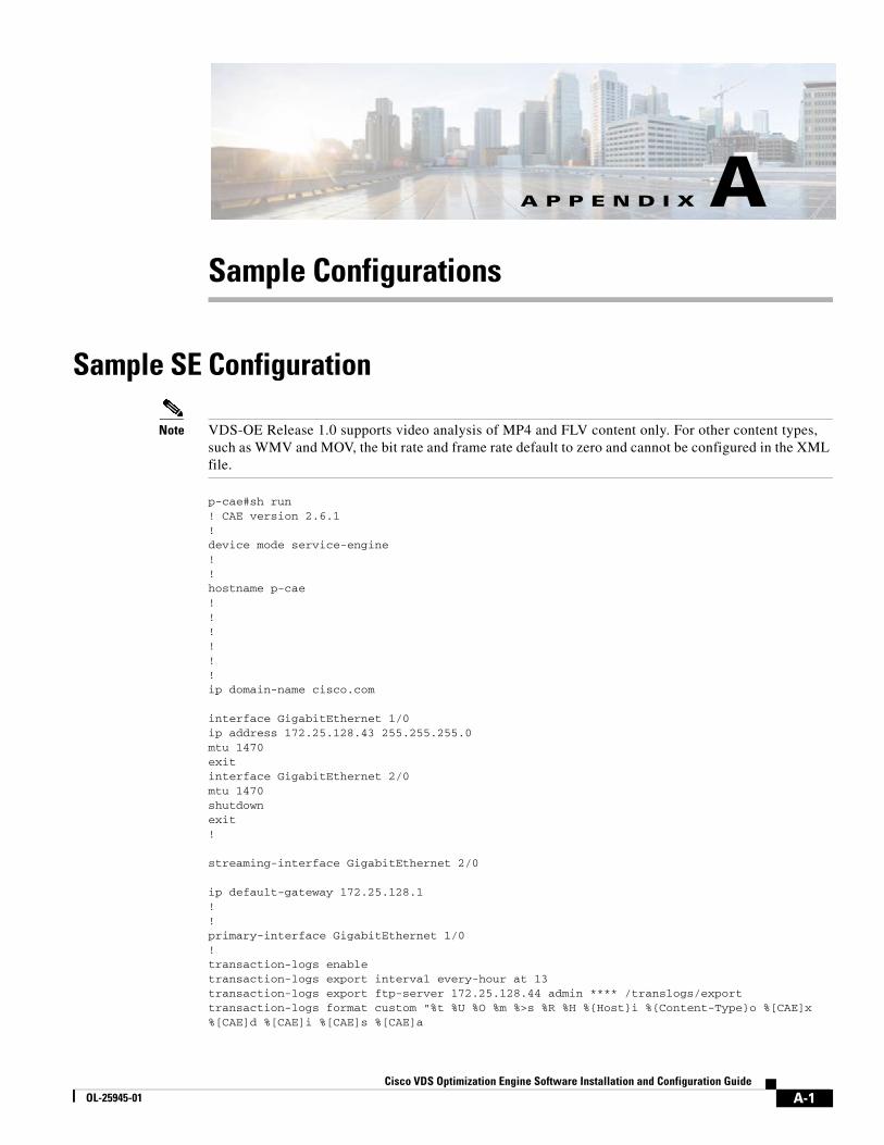
A-1Cisco VDS Optimization Engine Software Installation and Configuration Guide
OL-25945-01
A P P E N D I X ASample Configurations
Sample SE Configuration
Note VDS-OE Release 1.0 supports video analysis of MP4 and FLV content only. For other content types, such as WMV and MOV, the bit rate and frame rate default to zero and cannot be configured in the XML file.
p-cae#sh run! CAE version 2.6.1!device mode service-engine!!hostname p-cae!!!!!!ip domain-name cisco.com
interface GigabitEthernet 1/0ip address 172.25.128.43 255.255.255.0mtu 1470exitinterface GigabitEthernet 2/0mtu 1470shutdownexit!
streaming-interface GigabitEthernet 2/0
ip default-gateway 172.25.128.1!!primary-interface GigabitEthernet 1/0!transaction-logs enabletransaction-logs export interval every-hour at 13transaction-logs export ftp-server 172.25.128.44 admin **** /translogs/exporttransaction-logs format custom "%t %U %O %m %>s %R %H %{Host}i %{Content-Type}o %[CAE]x %[CAE]d %[CAE]i %[CAE]s %[CAE]a

A-2Cisco VDS Optimization Engine Software Installation and Configuration Guide
OL-25945-01
Appendix A Sample Configurations Sample OFAM Configuration
%[CAE]b %[CAE]v %[CAE]o %{User-Agent}i"!!!!!ip name-server 171.70.168.183ip name-server 171.68.226.120!!!logging console enable
cdsm ip 172.25.128.44cms enable!!!!!!cae enablecae xcode server ip 172.25.128.152 port 8062cae web-engine aim primary-ip 172.25.128.57 port 8001cae web-engine aim secondary 172.25.128.58
Sample OFAM Configuration! CAE version 2.6.1!device mode service-engine!!hostname p-cae!!!!!!ip domain-name cisco.com!!!!!!interface GigabitEthernet 1/0ip address 172.25.128.43 255.255.255.0mtu 1470exitinterface GigabitEthernet 2/0mtu 1470shutdownexit!streaming-interface GigabitEthernet 2/0!!ip default-gateway 172.25.128.1!

A-3Cisco VDS Optimization Engine Software Installation and Configuration Guide
OL-25945-01
Appendix A Sample Configurations Sample OFAM Configuration
!primary-interface GigabitEthernet 1/0!!!!!ip name-server 171.70.168.183ip name-server 171.68.226.120!!!logging console enable!cae enablecae ofam-mode enablecae xcode server ip 172.25.128.152 port 8062cae adaptation-rule file /state/contentAdptFiles/factory.xml
cae source-content-group blacklist 56.commatch referrer "56img.com"match http-header Server "Tengine"match http-header Content-Type "flv"exit!
cae source-content-group blacklist youku.commatch user-agent "Lavf"match http-header Server "YOUKU"match http-header Content-Type "flv"exit!aim asset-managerdevice-class SmallScreenDevicepriority 2match http user-agent .*HD7.*match http user-agent .*HTC.*match http user-agent .*MOT-ME811.*match http user-agent .*Nexus.S.4G.*match http user-agent .*Nokia.*match http user-agent .*SGH.*match http user-agent .*iPhone.*match http user-agent .*Windows\s*Phone.*exit!device-class BigScreenDevicepriority 1match http user-agent .*Chrome.*match http user-agent .*Firefox.*match http user-agent .*GT-P7500.*match http user-agent .*iPad.*match http user-agent .*Kindle.Fire.*match http user-agent .*MSIE.*match http user-agent .*Macintosh.*match http user-agent .*Moz.*match http user-agent .*Red.*match http user-agent .*Tablet.*match http user-agent .*Windows.*exit!device-class AnyDevicepriority 0match http user-agent .*exit

A-4Cisco VDS Optimization Engine Software Installation and Configuration Guide
OL-25945-01
Appendix A Sample Configurations Sample MVG Configuration
!popularity-class AnyDevicepriority 0threshold one-day 2match-rule user-agent .*exit!exit!no authsvr enable
Sample MVG Configurationcae-group lab local-addr 10.75.173.245 server se77 addr 10.74.31.77 port 80 server se78 addr 10.74.31.78 port 80 server se72 addr 10.74.31.72 port 80 keepalive-server interval 10 num-retry 3 timeout 3 deadtime 120 port 80
#exit#exit
Sample Adaptation XML File<?xml version="1.0" encoding="UTF-8"?><CAEGlobalConfig xmlns:xsi="http://www.w3.org/2001/XMLSchema-instance" xsi:noNamespaceSchemaLocation="CAEGlobalConfig.xsd"> <Revision>1.0</Revision> <CustomerName>TBD</CustomerName> <Rule_Patterns> <DeviceClass id=”iPhone”> <Template> cae-template-iPhone-h264 </Template> <Template> cae-template-iPhone-vp6 </Template> </DeviceClass>
<DeviceClass id=”iPad”> <Template> cae-template-iPad-h264 </Template> <Template> cae-template-iPad-vp6 </Template> </DeviceClass>
<DeviceClass id=”galaxy”> <Template> cae-template-galaxy-h264 </Template> <Template> cae-template-galaxy-vp6 </Template> </DeviceClass>
<PatternListGrp id="Apple_API_0"> <DeviceClass>iPhone</DeviceClass> <!—either iPhone or iPad --> <DeviceClass>iPad</DeviceClass> <AdapatationProfileIdx>0</AdapatationProfileIdx> <InputVideoRateStartEnd>500000-2000000 </InputVideoRateStartEnd> <InputVideoFrameRateStartEnd>20-50</InputVideoFrameRateStartEnd> <MatchedParnterGrp>gold-partner</MatchedParnterGrp> <!--<AccessNetwork>3g</AccessNetwork>--> <ContentSourceType>mp4</ContentSourceType> </PatternListGrp>

A-5Cisco VDS Optimization Engine Software Installation and Configuration Guide
OL-25945-01
Appendix A Sample Configurations Sample Adaptation XML File
<PatternListGrp id="iPhone_API_3"> <DeviceClass>iPhone</DeviceClass> <AdapatationProfileIdx>0</AdapatationProfileIdx> </PatternListGrp>
<PatternListGrp id="Samsung_API_3"> <DeviceClass>Galaxy</DeviceClass> <AdapatationProfileIdx>0</AdapatationProfileIdx> </PatternListGrp>
</Rule_Patterns>
<Rule_Actions> <Rule_SetAction name="BasicUserService"> <SetParameter name="Progressive-Video"> <MaxCompressionRatio>50</MaxCompressionRatio> <Resolution>320x240</Resolution> <MinBitRate>200000</MinBitRate> <OutputBitRate>300000</OutputBitRate> <OutputFrameRate>15</OutputFrameRate> <Pacing>0</Pacing> </SetParameter>
<SetParameter name="ABR-Rate-Delete"> <StartEnd>2000000-4000000</StartEnd> <StartEnd>800000-160000</StartEnd> </SetParameter>
<SetParameter name="ABR-Rate-Insert"> <StartEnd>100000-200000</StartEnd> <InsertRate>150000</InsertRate> </SetParameter> </Rule_SetAction>
<Rule_SetAction name=”Silver-User-Action> <SetParameter name="Progressive-Video"> <MaxCompressionRatio>40</MaxCompressionRatio> <MinBitRate>240000</MinBitRate> <OutputBitRate>320000</OutputBitRate> <Pacing>0</Pacing> </SetParameter>
<SetParameter name="ABR-Rate-Delete"> <StartEnd>2000000-4000000</StartEnd> <StartEnd>800000-160000</StartEnd> </SetParameter>
<SetParameter name="ABR-Rate-Insert"> <StartEnd>200000-300000</StartEnd> <InsertRate>250000</InsertRate> </SetParameter> </Rule_SetAction>
<PatternList_Action_Map> <SetParameter matchGroup="Apple_API_0"> <Action>Basic-User-Action </Action> </SetParameter>
<SetParameter matchGroup="iPhone_API_3"> <Action>Silver-User-Action </Action> </SetParameter>
<SetParameter matchGroup="Samsung_API_3">

A-6Cisco VDS Optimization Engine Software Installation and Configuration Guide
OL-25945-01
Appendix A Sample Configurations Sample Adaptation XML File
<Action>Silver-User-Action </Action> </SetParameter> </PatternList_Action_Map>
</Rule_Actions>
</CAEGlobalConfig>
B-1Cisco VDS Optimization Engine Software Installation and Configuration Guide
OL-25945-01
A P P E N D I X BCLI Commands
Global ConfigurationGlobal configurations are downloaded to CAE nodes from CDSM through a device group. After downloading, the commands are wrapped in XML file format and transported to the CAE cluster using the HTTPS protocol.
Enable/Disable CAECAE capability is enabled by default, but can be disabled globally, that is, for all CAE nodes.
Syntax
Use this command to enable CAE capability on this node:
cae enable
Use the no form of this command to disable CAE on this node:
no cae enable
Enable/Disable CAE OFAM Mode
Use the following CLI commands to control all OFAM processes when in CAE-SE mode.
Syntax
Use this command to restrain all OFAM processes when in CAE-SE mode.
cae ofam-mode enable
Note You can only enter this command if cae enable is configured. Once configured, it will launch the OFAM (AIM, Offline Manager, and Fetcher) processes.
Use the no form of this command to stop the OFAM (AIM, Offline Manager, and Fetcher) processes.
no cae ofam-mode enable
Use this command to enable the CAE feature.
cae enable

B-2Cisco VDS Optimization Engine Software Installation and Configuration Guide
OL-25945-01
Appendix B CLI CommandsGlobal Configuration
Note This command launches the OFAM processses only if cae ofam-mode enable is configured.
Use the no form of this command to disable CAE processes, including OFAM processes.
no cae enable
Enable/Disable OFAMThe OFAM mode or service is not enabled by default, but you can enable it through the CLI.
Syntax
Use this command to enable OFAM capability for the node:
cae ofam-mode enable
Use the no form of this command to disable OFAM for the node:
no cae ofam-mode enable
Note These commands can be entered only if "cae enable" is configured.
Transcoder Server IP AddressWebEngine and Offline Manager both communicate with the Transcoder server to submit transcoding jobs. To establish communication with the Transcoder server, its IP address must be specified in advance.
Use the following command to allow WebEngine or Offline Manager to specify the Transcoder server IP address so it can communicate with the Transcoder server.
cae xcode server ip <x.x.x.x> port <port_number>
where <x.x.x.x> is the server IP address and <port_number> is the port number of the Transcoder server.
Note The default port number for the Transcoder server is 8062.
NAS EvictionUse these commands to set the frequency and high and low trigger thresholds (“water marks”) for NAS eviction.
cae nas eviction frequency 2 // default to every 2 hourscae nas eviction high-water-mark 75cae nas eviction low-water-mark 65
Note All of these commands have corresponding controls in the CDSM GUI.
B-3Cisco VDS Optimization Engine Software Installation and Configuration Guide
OL-25945-01
Appendix B CLI CommandsGlobal Configuration
IP Address RangeThe Transparent Proxy feature requires that a range of IP address be configured for every CAE card. Use the following commands to configure an IP address range for each card.
IP Interface
Use this command to specify the CAE card that is to receive the subsequent CLI command.
cds(config)#interface <port_type> <chassis/slot>
Where <port_type> is the port used to communicate with the card <chassis/slot> is the chassis and slot number of the CAE card to be configured.
IP Address Range
Use this command to specify the IP address range and subnet mask for the CAE card to be configured.
cds(config-if)#ip address range <ip_address_start> <ip_address_end> <subnet_mask>
Where <ip_address_start>, <ip_address_end>, and <subnet_mask> are the starting address, ending address, and IP subnet mask for the card, respectively.
Example
In the following example, the CAE card in chassis 1, slot 0 is specified for communication via its Gigabit Ethernet port. Then, the card is configured with IP address range 172.25.128.45 through 49 and subnet mask 255.255.0.0.
cds(config)#interface GigabitEthernet 1/0cds(config-if)#ip address range 172.25.128.45 172.25.128.49 255.255.0.0
Adaptation ConfigurationThe objective of an adaptation configuration is to define the transcoding, ABR manifest file manipulation, and pacing actions that are needed for a particular input video or manifest file.
The adaptation configuration is used for both online and offline transcoding. It is used by WebEngine for online transcoding, and by CAE Offline Manager for offline transcoding.
Note We do not recommend changing the adaptation configuration through the CLI, as the XML file is downloaded from CDSM.
Content Source GroupA content source group defines the business partners for the service provider so that different adaptation policies can be applied for different business partners. Use the following command to define a content source group.
cae content-source-group gold-partner domain www.youtube.com // match any of them domain www.netflix.com domain www.cnn.com
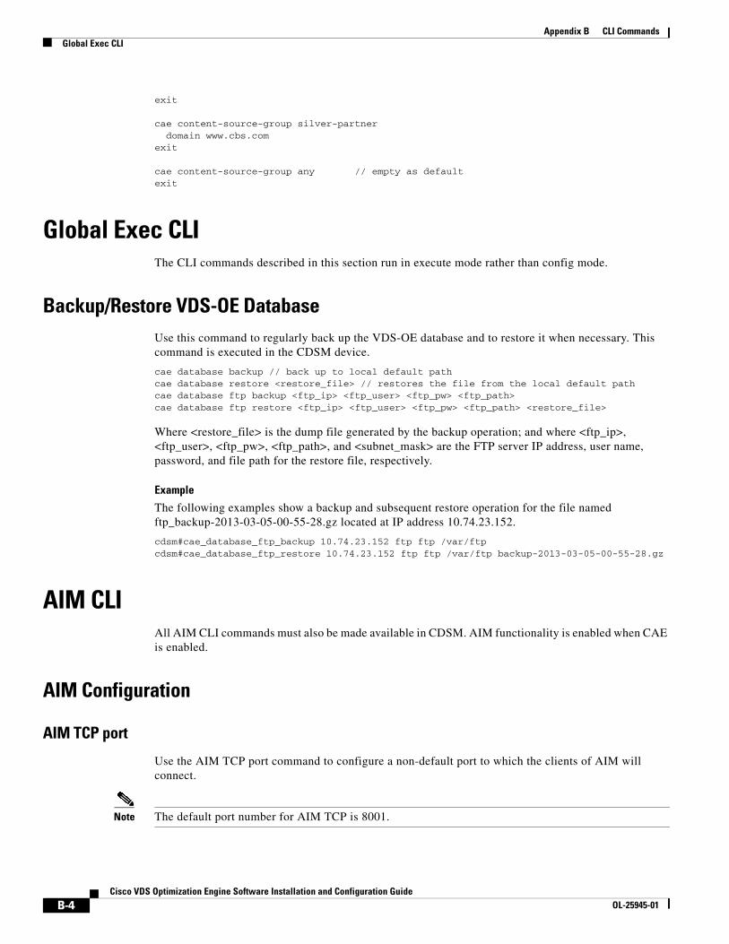
B-4Cisco VDS Optimization Engine Software Installation and Configuration Guide
OL-25945-01
Appendix B CLI CommandsGlobal Exec CLI
exit
cae content-source-group silver-partner domain www.cbs.comexit
cae content-source-group any // empty as defaultexit
Global Exec CLIThe CLI commands described in this section run in execute mode rather than config mode.
Backup/Restore VDS-OE DatabaseUse this command to regularly back up the VDS-OE database and to restore it when necessary. This command is executed in the CDSM device.
cae database backup // back up to local default pathcae database restore <restore_file> // restores the file from the local default pathcae database ftp backup <ftp_ip> <ftp_user> <ftp_pw> <ftp_path>cae database ftp restore <ftp_ip> <ftp_user> <ftp_pw> <ftp_path> <restore_file>
Where <restore_file> is the dump file generated by the backup operation; and where <ftp_ip>, <ftp_user>, <ftp_pw>, <ftp_path>, and <subnet_mask> are the FTP server IP address, user name, password, and file path for the restore file, respectively.
Example
The following examples show a backup and subsequent restore operation for the file named ftp_backup-2013-03-05-00-55-28.gz located at IP address 10.74.23.152.
cdsm#cae_database_ftp_backup 10.74.23.152 ftp ftp /var/ftpcdsm#cae_database_ftp_restore 10.74.23.152 ftp ftp /var/ftp backup-2013-03-05-00-55-28.gz
AIM CLIAll AIM CLI commands must also be made available in CDSM. AIM functionality is enabled when CAE is enabled.
AIM Configuration
AIM TCP port
Use the AIM TCP port command to configure a non-default port to which the clients of AIM will connect.
Note The default port number for AIM TCP is 8001.
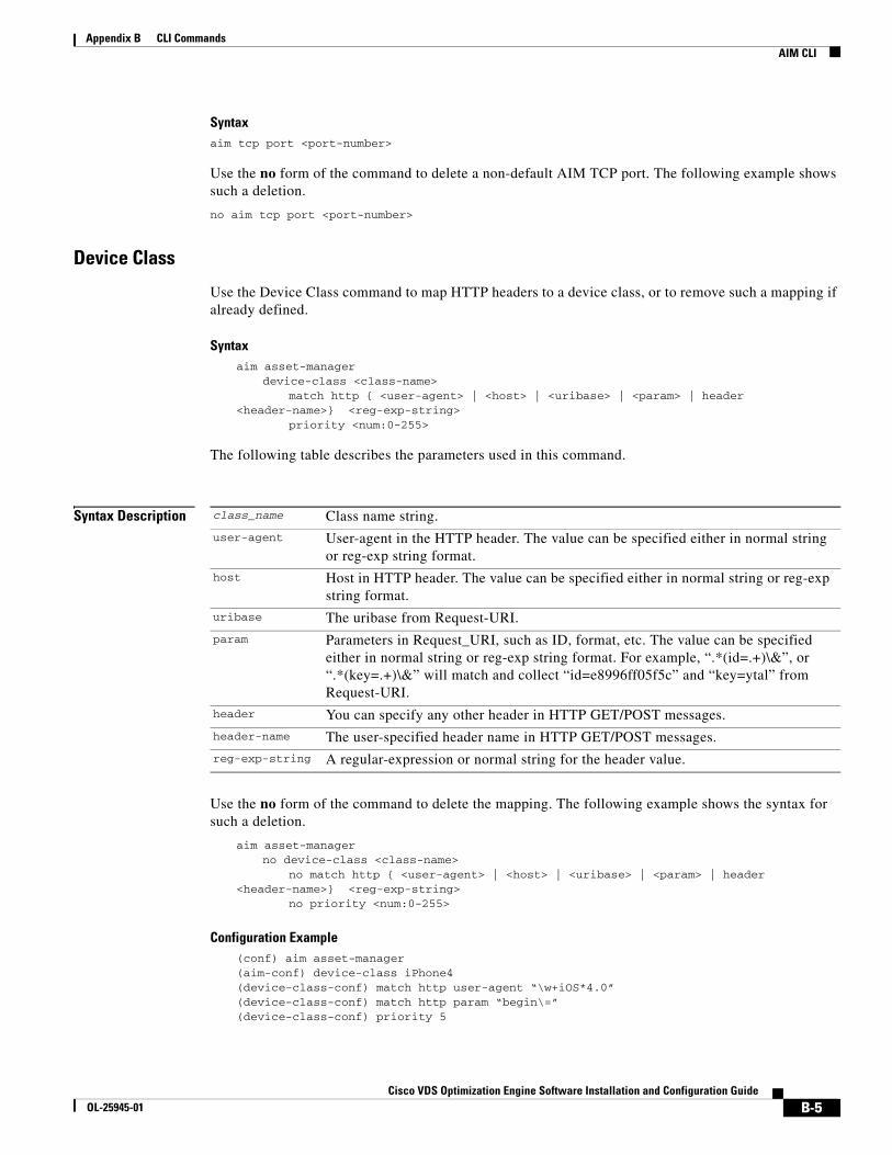
B-5Cisco VDS Optimization Engine Software Installation and Configuration Guide
OL-25945-01
Appendix B CLI CommandsAIM CLI
Syntaxaim tcp port <port-number>
Use the no form of the command to delete a non-default AIM TCP port. The following example shows such a deletion.
no aim tcp port <port-number>
Device Class
Use the Device Class command to map HTTP headers to a device class, or to remove such a mapping if already defined.
Syntaxaim asset-manager
device-class <class-name>match http { <user-agent> | <host> | <uribase> | <param> | header
<header-name>} <reg-exp-string>priority <num:0-255>
The following table describes the parameters used in this command.
Syntax Description
Use the no form of the command to delete the mapping. The following example shows the syntax for such a deletion.
aim asset-managerno device-class <class-name>
no match http { <user-agent> | <host> | <uribase> | <param> | header <header-name>} <reg-exp-string>
no priority <num:0-255>
Configuration Example(conf) aim asset-manager(aim-conf) device-class iPhone4(device-class-conf) match http user-agent “\w+iOS*4.0”(device-class-conf) match http param “begin\=”(device-class-conf) priority 5
class_name Class name string.
user-agent User-agent in the HTTP header. The value can be specified either in normal string or reg-exp string format.
host Host in HTTP header. The value can be specified either in normal string or reg-exp string format.
uribase The uribase from Request-URI.
param Parameters in Request_URI, such as ID, format, etc. The value can be specified either in normal string or reg-exp string format. For example, “.*(id=.+)\&”, or “.*(key=.+)\&” will match and collect “id=e8996ff05f5c” and “key=ytal” from Request-URI.
header You can specify any other header in HTTP GET/POST messages.
header-name The user-specified header name in HTTP GET/POST messages.
reg-exp-string A regular-expression or normal string for the header value.

B-6Cisco VDS Optimization Engine Software Installation and Configuration Guide
OL-25945-01
Appendix B CLI CommandsAIM CLI
(conf) aim asset-manager(aim-conf) device-class iPad(device-class-conf) match http user-agent reg-exp “iPad”(device-class-conf) match http param reg-exp “begin\=”(device-class-conf) priority 3
Popularity Configuration
Use popularity configuration to define popularity settings such as the threshold for triggering adaptation, the video selection, and so on.
Syntaxaim popularity class <class name>
threshold 1min <value> 1hr <value> 4hr <value> 1day <value>expiry <number seconds>
match-rule [host | uribase | param | http-header <header type>] <regexp>
The following table describes the parameters used in this command.
Syntax Description
Use the no form of this command to delete a popularity class definition.
no aim popularity class <class name>no threshold 1min <value> 1hr <value> 4hr <value> 1day <value>
no expiry <number seconds>no match-rule [host | uribase | param | http-header <header type>] <regexp>
Configuration Example(conf) aim asset-manager (aim-conf) aim popularity class popclass (aim-conf-popclass) threshold 1min 10 1hr 100 4hr 200 1day 500 (aim-conf-popclass) expiry 6000 (aim-conf-popclass) match-rule host “*youtube*”
Blacklist/Whitelist
Use the following CLI command to configure the blacklist or whitelist as needed.
Syntaxcae source-content-group {blacklist | default | whitelist}
The following table describes the parameters used in this command.
class name Popularity class name.
thresholds Values for per minute, per hour, per 4-hour interval, and per day (range 1 to 2147483647).
expiry Content expiration time in seconds (range 1 to 2147483647).
match-rule <header type> can be any type defined in the HTTP header. Refer to HTTP parser section.
regexp Pattern string

B-7Cisco VDS Optimization Engine Software Installation and Configuration Guide
OL-25945-01
Appendix B CLI CommandsAIM Show Commands
Syntax Description
AIM Show Commands
AIM Device Class Information Use this command to display information for all AIM device classes or for a specific AIM device class.
Syntaxshow aim device-class {all | name <device-class-name>}
Use the all option to show information for all device classes, or name to show information for a particular device class specified in <device-class-name>.
Exampleswitch# show aim device-class name device-class1Device Class: device-class1Priority : 1Total 2 matching rulesMatch User Agent : AndroidMatch host : google.com
Note The show aim database command does not support the Beginning (Beg) option.
AIM Popularity Class InformationUse this command to display information for all AIM popularity classes or for a selected AIM popularity class.
Syntaxshow aim popularity-class {all | name <popularity-class-name>}
Use the all option to show information for all popularity classes, or name to show information for a particular popularity class specified in <popularity-class-name>.
Exampleswitch# show aim popularity-class all Popularity class: pop-class-1 Match-rule: Host (.*video.*) Expiry time: 1800 seconds Threshold: 1-minute: 10 1-hour: 50 4-hour: 200
blacklist Configure blacklist
deafult Restore the default setting
whitelist Configure whitelist
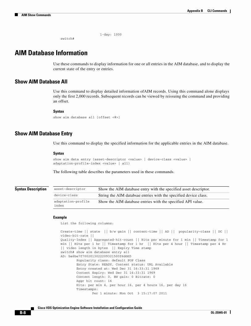
B-8Cisco VDS Optimization Engine Software Installation and Configuration Guide
OL-25945-01
Appendix B CLI CommandsAIM Show Commands
1-day: 1000switch#
AIM Database InformationUse these commands to display information for one or all entries in the AIM database, and to display the current state of the entry or entries.
Show AIM Database All
Use this command to display detailed information ofAIM records. Using this command alone displays only the first 2,000 records. Subsequent records can be viewed by reissuing the command and providing an offset.
Syntaxshow aim database all [offset <#>]
Show AIM Database Entry
Use this command to display the specified information for the applicable entries in the AIM database.
Syntaxshow aim data entry {asset-descriptor <value> | device-class <value> | adaptation-profile-index <value> | all}
The following table describes the parameters used in these commands.
Syntax Description
ExampleList the following columns:
Create-time || state || b/w gain || content-time || AD || popularity-class || DC || video-bit-rate || Quality-Index || Aggregated-hit-count || Hits per minute for 1 min || Timestamp for 1 min || Hits per 1 hr || Timestamp for 1 hr || Hits per 4 hour || Timestamp per 4 Hr || video length in bytes || Expiry Time stampswitch# show aim database entry all AD: ba6be7f7002013022209321500f6ddd3 Popularity class: default POP Class Entry State: READY, Content status: URL Available Entry created at: Wed Dec 31 16:33:31 1969 Content Expiry: Wed Dec 31 16:33:31 1969 Content length: 0, BW gain: 0 Bitrate: 0 Aggr hit count: 16 Hits: per min 4, per hour 16, per 4 hours 16, per day 16 Timestamps: Per 1 minute: Mon Oct 3 15:17:07 2011
asset-descriptor Show the AIM database entry with the specified asset descriptor.
device-class String the AIM databsae entries with the specified device class.
adaptation-profile index
Show the AIM database entries with the specified API value.

B-9Cisco VDS Optimization Engine Software Installation and Configuration Guide
OL-25945-01
Appendix B CLI CommandsAIM Show Commands
Per 1 hour: Mon Oct 3 15:10:07 2011 Per 4 hours: Mon Oct 3 15:10:07 2011 Per 1 day: Mon Oct 3 15:10:07 2011
switch#
Show AIM Database Summary
This command provides the number of AIM records in the database along with a breakdown of the number of records in each state.
Syntaxshow aim database summary
Show AIM Database State
Use this command to display the entries in the AIM database that are currently in a specified state.
Syntaxshow aim database state {1 | 2 | 3 | 4}
The following table describes the parameters used in these commands.
Syntax Description
AIM Statistics
Use this command to display statistics for the AIM database. You can display all statistics or a specified subset of statistics.
Syntaxshow aim statistics {content-retrieval | content-adaptation | http | all | content-popularity-update}
Note This command does not support the use of single quotes for the domain value.
Syntax Description
1 Show Created AIM database entries only.
2 Show Adapting AIM database entries only.
3 Show Ready AIM database entries only.
4 Show Ready-Adapting AIM database entries only.
content-retrieval Show AIM content-retrieval statistics.
content-adaptation Show AIM content adatpation statistics.
http Show AIM HTTP statistics.all Show all AIM statistics.
content-popularity-update
show all AIM content-popularity updates.
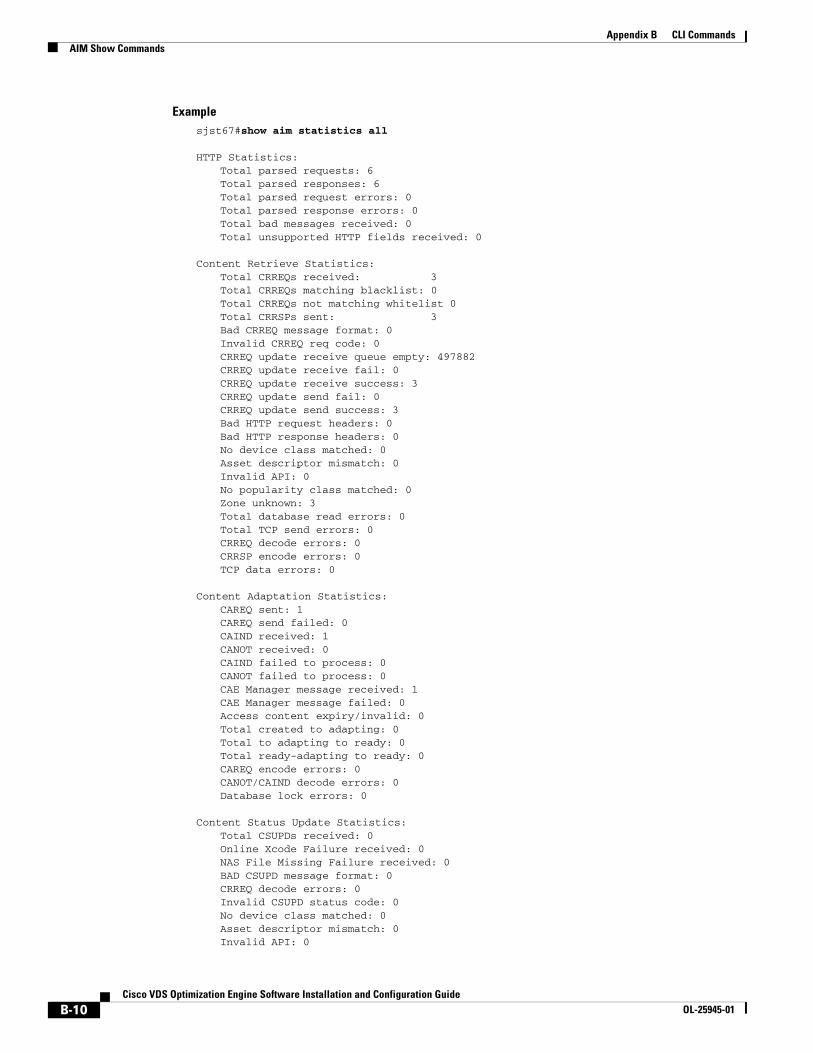
B-10Cisco VDS Optimization Engine Software Installation and Configuration Guide
OL-25945-01
Appendix B CLI CommandsAIM Show Commands
Examplesjst67#show aim statistics all
HTTP Statistics:Total parsed requests: 6Total parsed responses: 6Total parsed request errors: 0Total parsed response errors: 0Total bad messages received: 0Total unsupported HTTP fields received: 0
Content Retrieve Statistics:Total CRREQs received: 3Total CRREQs matching blacklist: 0Total CRREQs not matching whitelist 0Total CRRSPs sent: 3Bad CRREQ message format: 0Invalid CRREQ req code: 0CRREQ update receive queue empty: 497882CRREQ update receive fail: 0CRREQ update receive success: 3CRREQ update send fail: 0CRREQ update send success: 3Bad HTTP request headers: 0Bad HTTP response headers: 0No device class matched: 0Asset descriptor mismatch: 0Invalid API: 0No popularity class matched: 0Zone unknown: 3Total database read errors: 0Total TCP send errors: 0CRREQ decode errors: 0CRRSP encode errors: 0TCP data errors: 0
Content Adaptation Statistics:CAREQ sent: 1CAREQ send failed: 0CAIND received: 1CANOT received: 0CAIND failed to process: 0CANOT failed to process: 0CAE Manager message received: 1CAE Manager message failed: 0Access content expiry/invalid: 0Total created to adapting: 0Total to adapting to ready: 0Total ready-adapting to ready: 0CAREQ encode errors: 0CANOT/CAIND decode errors: 0Database lock errors: 0
Content Status Update Statistics:Total CSUPDs received: 0Online Xcode Failure received: 0NAS File Missing Failure received: 0BAD CSUPD message format: 0CRREQ decode errors: 0Invalid CSUPD status code: 0No device class matched: 0Asset descriptor mismatch: 0Invalid API: 0
B-11Cisco VDS Optimization Engine Software Installation and Configuration Guide
OL-25945-01
Appendix B CLI CommandsAIM Clear Commands
Total database write errors: 0Total database read errors: 0
Content Popularity Update Statistics:Total CPUPDs received: 3Total CPUPDs matching blacklist: 0Total CPUPDs not matching whitelist: 0Bad HTTP request headers: 0Bad HTTP response headers: 0No device class matched: 0Asset descriptor mismatch: 0Invalid API: 0No popularity class matched: 0Total database read errors: 0Total database write errors: 0CPUPD decode errors: 0
sjst67#
AIM Clear Commands
AIM Clear StatisticsUse this command to remove all AIM statistics from the database.
Syntaxclear aim statistics all
Syntax Description
ExampleCD4-OFAM#clear aim statistics all
AIM Clear Database Rows
Purpose
Use this command to remove all rows from the AIM database, or only rows that match a specified condition.
Syntaxclear aim database {aim-id <value> | all | asset-descriptor <value> | state <value>}
ExampleCD4-OFAM#clear aim database all
Syntax Description
all Clears all AIM statistics.
aim-id Clear AIM database rows that match the AIM ID.
all Clear all AIM database rows.

B-12Cisco VDS Optimization Engine Software Installation and Configuration Guide
OL-25945-01
Appendix B CLI CommandsWeb Engine CLI
Purpose
Use this command to display all logs of a specified type from the AIM database for debugging purposes.
Syntaxdebug aim all {detail | error | trace}
AIM Debug
Syntax Description
Web Engine CLI
Web Engine ConfigurationThe service engine (SE) with WebEngine enhancement for CAE is part of the CAE cluster. This command allows the WebEngine MVG helper to connect to the AIM.
cae aim primary-ip <x.x.x.x> [secondary-ip <x.x.x.x>] [port 8001]
Note From the perspective of CDSM, this is a per-node or per-device configuration.
Web Engine Show StatisticsUse these commands to display WebEngine statistics.
Syntaxshow statistics web-engine <detail>
where <detail> is an optional parameter used to request a more detailed output.
Note This command does not support the use of single quotes for the domain value.
Note We advise against using the Cache Miss and Cache Hit counters to determine how frequently videos are accessing offline fetched content. Instead, we suggest using Transcoded Offline Content and Transcoded Online Content statistics to measure how often offline data is being accessed.
asset-descriptor Clear AIM database rows that match the asset descriptor.
state Clear AIM database rows that match the state.
detail Display AIM log level detail.
error Display AIM log level error.
trace Display AIM log level trace.

B-13Cisco VDS Optimization Engine Software Installation and Configuration Guide
OL-25945-01
Appendix B CLI CommandsWeb Engine CLI
Examples General Form#show statistics web-engine
HTTP Request Info Statistics-----------------------Num Lookups : 12066Preposition Hit : 0Alien Hit : 0Cache Hit : 0Cache Miss : 862Partial Cache Hit : 0Cache Bypass : 13837Live Miss : 0Live Hit : 0ASX Meta Response : 0Error Response Miss : 1Error Response Hit : 0// The following are new CAE outputsServing Xcoded Offline : 20Serving Xcoded Online : 25
Detailed Formshow statistics web-engine detail
HTTP Request Info Statistics-----------------------Num Lookups : 114 Preposition Hit : 0 External Hit : 0 Cache Hit : 0 Cache Miss : 114 Partial Cache Hit : 0 Cache Bypass : 0 Live Miss : 0 Live Hit : 0 ASX Meta Response : 0
HTTP Request Type Statistics-----------------------Get Requests : 114 Post Requests : 4 Head Requests : 0 Put Requests : 0 Delete Requests : 0 Trace Requests : 0 Options Requests : 0 Connect Requests : 0 Patch Requests : 0 Unknown HTTP Method Requests : 0 Range Requests Received : 15 Range Requests Sent : 20 Revalidation Requests Received : 15 Revalidation Requests Sent : 20 Liveness Query : 0 CAE Liveliness Requests : 0 WMT(http) Redirected Requests : 0 Local Requests : 0 Play Live Requests : 0 Total Outgoing Requests : 123
HTTP Authorization Statistics----------------------
B-14Cisco VDS Optimization Engine Software Installation and Configuration Guide
OL-25945-01
Appendix B CLI CommandsCAE Offline Manager CLI
Authorization Allow : 0 Authorization No Cache : 0 Authorization Force Revalidate : 0 Authorization Deny : 0
Web Engine Show Cached ContentUse this command to display local Web Engine cached content.
Syntaxshow cache content
Web Engine Debug
Purpose
Use this command to display all logs of a specified type from the Web Engine database for debugging purposes. Error logs are displayed by default, but detail or trace logs also may be specified.
Syntaxdebug web-engine {detail | error | trace}
Syntax Description
CAE Offline Manager CLI
General Settings
The following settings can be made for Offline Manager:
• Own Server Port – IPC TCP listening port for the AIM
• Original Input Directory – location where Fetcher saves its downloaded original files
• Transcoding Output Directory – location where CTM Server saves transcoded files
• Transcoder Job Request Timeout – time Offline Manager waits for each transcoding job request
Default settings for each parameter are in place, but can be modified using CLI commands as follows to suit the needs of each deployment.
#cae offline-mgr server port 8002 // default to 8002#cae input-location directory input#cae output-location directory output#cae xcode timer 2200 // default to 1800
detail Display Web Engine log level detail.
error Display Web Engine log level error (default).
trace Display Web Engine log level trace.
B-15Cisco VDS Optimization Engine Software Installation and Configuration Guide
OL-25945-01
Appendix B CLI CommandsCAE Offline Manager CLI
From the perspective of the AIM process, Offline Manager is a TCP server. This is a per-device configuration and applies to the location where Offline Manager is running.
OFAM Enable-Disable
You can enable and disable OFAM processes using CLI commands, as shown in the following examples.
ExampleCAE(config)#cae ofam mode-enable //This can only be entered if cae enable is configured. once configured, it will launch the OFAM (AIM, Offline Manager, and Fetcher) processes.
CAE(config)#no cae ofam-mode enable //This command stops the OFAM (AIM, Offline Manager, and Fetcher) processes.
CAE(config)#cae enable //This command enables the CAE feature. Whether OFAM processes are launched depends on if “cae ofam-mode enable” is configured.
CAE(config)#no cae enable //This command disables CAE processes, including the OFAM processes.
Fetcher IP and Port
By default, the Offline Manager always connects to a local Fetcher - that is, one running on the same node. Offline Manager and Fetcher connect using the default port. This is a per-device configuration, and applies to the location where Offline Manager is running.
Note The default port is 8003.
You can choose to use an external Fetcher by entering its corresponding IP address and port. For the purpose of defining the TCP connection between Offline Manager and Fetcher, Offline Manager is a TCP client and Fetcher is a TCP server.
Example
If Offline Manager and Fetcher are located in different nodes, or if a non-default port is used, the following CLI serves the purpose:
CAE(config)#cae offline-mgr fetcher <ip a.b.c.d> [port 8002]#cae offline-mgr fetcher ip 172.25.128.43 port 8003
This line can be repeated as needed in order to configure multiple Fetchers.
Original Input
This is the location where Fetcher saves the content from the original server.
CAE(config)#cae input-location directory input
From the perspective of CDSM, this is a per-node configuration so that different nodes can save files to different directories. This command is synchronized to the CDSM GUI.

B-16Cisco VDS Optimization Engine Software Installation and Configuration Guide
OL-25945-01
Appendix B CLI CommandsCAE Offline Manager CLI
Transcoded Output
This is the location where the CTM node saves its transcoded output video content.
CAE(config)#cae output-location directory output
From the perspective of CDSM, this is a per-node configuration so that different nodes can save files to different directories. This command is synchronized to the CDSM GUI.
Transcoder Timer
Use this command to specify the time that Offline Manager waits for each job to be submitted to the CTM server.
CAE xcode timer 2200 // wait 2200 seconds
This command is synchronized to the CDSM GUI.
Adaptation XML File
The adaptation XML file defines the transcoding rules used by both the Offline Manager and the Web Engine. The CDSM uses this CLI command to inform both applications of a new adaptation XML file rule.
CAE adaptation-rule file /state/contentAdaptFile/cae_v2.xml
Note A file configured locally with this command is not reflected in the CDSM GUI because the CLI cannot upload the content of the adaptation file into CDSM.
Offline Manager Show
Offline Manager Statistics show
Examples #show cae offline statistics //or #show cae offline-mgr statistics
Offline-Mgr Progressive Statistics CAREQ Requests Recv : 6 CAIND Response Sent : 0 CANOT Response Sent : 6 Fetch Requests Sent : 0 Fetch Response Recv : 0 Transcode Job Requests : 0 Transcode Job Response : 0 CAREQ Requests Recv failed : 0 CAIND Response Sent failed : 0 CANOT Response Sent failed : 0 Fetch Requests Sent failed : 0 Fetch Response Recv failed : 0 Transcode Job Requests failed : 0 Transcode Job Response failed : 0
Offline-Mgr HLS ABR Statistics Manifest CAREQ Requests Recv : 0
B-17Cisco VDS Optimization Engine Software Installation and Configuration Guide
OL-25945-01
Appendix B CLI CommandsCAE Offline Manager CLI
Manifest CAIND Response Sent : 0 Manifest CANOT Response Sent : 0 Manifest Fetch Requests Sent : 0 Manifest Fetch Response Recv : 0 Chunk Fetch Requests Sent : 0 Chunk Fetch Response Recv : 0 Chunk Transcode Job Requests : 0 Chunk Transcode Job Response : 0 Manifest CAREQ Requests Recv failed : 0 Manifest CAIND Response Sent failed : 0 Manifest CANOT Response Sent failed : 0 Manifest Fetch Requests Sent failed : 0 Manifest Fetch Response Recv failed : 0 Chunk Fetch Requests Sent failed : 0 Chunk Fetch Response Recv failed : 0 Chunk Transcode Job Requests failed : 0 Chunk Transcode Job Response failed : 0
Note This command does not support the use of single quotes for the domain value.
Offline Manager Job show
This command displays one or more CAE offline jobs currently in progress.
Syntax#show cae offline session all
Where <asset-descriptor> is an optional parameter that lets you to display details for a single job.
Example 1#show cae offline session allFetching ASSEST-ID-1 www.youtube.com/video.mp4Xcoding ASSEST-ID-2 www.youtube.com/video.mp4
Example 2#show cae offline session asset-descriptor <value>Asset-Desc: abbbemeppdnnssaaa2345URL: www.youtube.com/video.mp4State: XcodingDevice Class: iPhone4API: 4Xcode Template: CAE-iphone-medium-H.264-400x224-150kbps
Offline Manager Clear
#clear cae offline statistics [domain www.youtube.com]
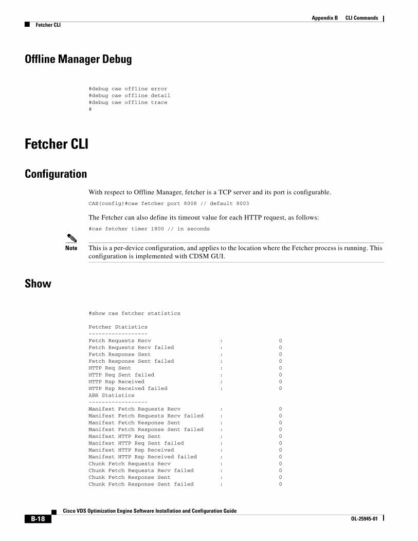
B-18Cisco VDS Optimization Engine Software Installation and Configuration Guide
OL-25945-01
Appendix B CLI CommandsFetcher CLI
Offline Manager Debug
#debug cae offline error#debug cae offline detail#debug cae offline trace#
Fetcher CLI
ConfigurationWith respect to Offline Manager, fetcher is a TCP server and its port is configurable.
CAE(config)#cae fetcher port 8008 // default 8003
The Fetcher can also define its timeout value for each HTTP request, as follows:
#cae fetcher timer 1800 // in seconds
Note This is a per-device configuration, and applies to the location where the Fetcher process is running. This configuration is implemented with CDSM GUI.
Show
#show cae fetcher statistics
Fetcher Statistics------------------Fetch Requests Recv : 0Fetch Requests Recv failed : 0Fetch Response Sent : 0Fetch Response Sent failed : 0HTTP Req Sent : 0HTTP Req Sent failed : 0HTTP Rsp Received : 0HTTP Rsp Received failed : 0ABR Statistics------------------Manifest Fetch Requests Recv : 0Manifest Fetch Requests Recv failed : 0Manifest Fetch Response Sent : 0Manifest Fetch Response Sent failed : 0Manifest HTTP Req Sent : 0Manifest HTTP Req Sent failed : 0Manifest HTTP Rsp Received : 0Manifest HTTP Rsp Received failed : 0Chunk Fetch Requests Recv : 0Chunk Fetch Requests Recv failed : 0Chunk Fetch Response Sent : 0Chunk Fetch Response Sent failed : 0

B-19Cisco VDS Optimization Engine Software Installation and Configuration Guide
OL-25945-01
Appendix B CLI CommandsFetcher CLI
Chunk HTTP Req Sent : 0Chunk HTTP Req Sent failed : 0Chunk HTTP Rsp Received : 0Chunk HTTP Rsp Received failed : 0
Note This command does not support the use of single quotes for the domain value.
Debug
#debug cae fetcher error#debug cae fetcher detail#debug cae fetcher trace

B-20Cisco VDS Optimization Engine Software Installation and Configuration Guide
OL-25945-01
Appendix B CLI CommandsFetcher CLI
GL-1Cisco VDS Optimzation Engine Software Installation and Configuration Guide
OL-25945-01
G L O S S A R Y
A
ABR Adaptive Bit Rate.
AD Asset descriptor; an identifier for original video.
AIM Asset Information Manager; a CAE process that maintains a database of video assets.
API Application Programming Interface; Adaptation Profile Index.
Armada Former product name for Cisco Transcode Manager (CTM).
C
CAE Content Adaptation Engine; the original name for VDS-OE, which still appears in some GUI elements.
CAE Controller CAE component responsible for handling the interface to MVG, managing transcoding operations through the CAE and CTM, and video delivery.
CAIND Content Adaptation Indication; a message sent from the Offline Manager to the AIM when content has been adapted by the transcoder.
CAL Content Abstraction Layer.
CAREQ Content Adaptation Request; a message sent from the AIM to the Offline Manager to initiate transcoding.
CDN Content Delivery Network.
CDS Content Delivery System.
CDSM Content Delivery System Manager.
CLI Command Line Interface.
CRREQ Content Retrieval Request; an IPC message sent from the CAE-SE (Web Engine) to the AIM to query whether offline transcoded content is available.
CRRSP Content Retrieval Response; an IPC message sent from the AIM to the CAE-SE to indicate whether offline transcoded codent is available, and if so, the location of the content.

Glossary
GL-2Cisco VDS Optimzation Engine Software Installation and Configuration Guide
OL-25945-01
CTM Cisco Transcode Manager; formerly called Armada.
Cisco Unified Fabric Techology that combines LAN and SAN networks into a single physical infrastructure using Fiber Channel over Ethernet (FCoE). By virtue of its use of 10 gigabit Ethernet (10-GE) converged network adapters (CNAs), this technology streamlines cabling, interface, and adapter requirements and provides increased capacity and enhanced redundancy at much lower total cost of ownership.
H
HA High Availability.
HLS HTTP Live Streaming; an Apple technology for streaming internet video.
Hypervisor Also called a virtual machine monitor (VMM); a virtualization application that allows multiple operating systems to run concurrently on a host computer. Type 1, or native, hypervisors are software systems that run directly on the host hoardware as a hardware control and gues operating system monoitor. Examples include VMWare ESX/ESXi Server, Xen, and Microsoft Hyper-V. Type II hypervisors run within a conventional operating system environment, such as Linux, and do not offer the scalability required for next-generation IP video applications.
I
IPC Inter-Process Communication.
K
KPI Key Performance Indicator.
M
MDC Media data center; a data center that also including decoders, encoders, and other equipment needed to support IP video ingest, storage, conditioning, and distribution. The Cisco MDC architecture is designed to host multiple services spanning a wide range of video and subscriber applications while providing the necessary access, redundancy, isolation, and security measures.
MVG Mobile Video Gateway.
N
NTP Network Time Protocol.
Glossary
GL-3Cisco VDS Optimzation Engine Software Installation and Configuration Guide
OL-25945-01
O
OFAM Offline Asset Manager; CAE component that combines the AIM, Offline Manager, and Fetcher processes.
Offline In the context of CAE, refers to video content that has been transcoded and stored before it is delivered to a user device.
Online In the context of CAE, refers to video content that is transcoded in real time as it is being delivered to a user device.
OS Operating System; Origin Server.
Q
QoS Quality of Service.
R
RAN Radio Access Network.
RAT Radio Access Technology.
S
SE Service Engine.
SIP Session Initiation Protocol.
SR Service Router.
SS Smooth Streaming; a Microsoft technology for streaming internet video.
T
TCPO TCP Transport Optimization.
TPO Transport Optimization such as TCPO or HTTP Data Optimization.
Transcode To convert the encoding scheme for a video to a different scheme for compatability with a specific system or device.
Transrate To convert the data rate of an encoded video stream for compatibility with a specific system or device.
Glossary
GL-4Cisco VDS Optimzation Engine Software Installation and Configuration Guide
OL-25945-01
U
UCS Unified Computing System.
UE User Equipment; especially, a mobile terminal.
V
VDS-OE Video Distribution Suite - Optimization Engine.
Virtualization The instantiation of one or more operating system environments in self-contained virtual machines that are independent of the computer hardware on which they run. This allows the operating system and its applications to be copied or moved from one hardware platform to another, and for multiple virtual machines to run on the same physical data-center server in isolation from each other, to improve the utilization of network resources.
VOD Video on Demand; video content offered for sale by a service provider or partner such as AT&T U-Verse or Verizon FiOS.
X
X-header In SIP, a header used to send non-standard information.