cisco unified communications system for ip telephony ... registrar, aironet, alltouch, asyncos,...
TRANSCRIPT
Cisco Unified Communications System for IP Telephony Release 8.0(2) First Published: April 2010 Revised: June 2010
Americas HeadquartersCisco Systems, Inc.170 West Tasman DriveSan Jose, CA 95134-1706 USAhttp://www.cisco.comTel: 408 526-4000
800 553-NETS (6387)Fax: 408 527-0883

THE SPECIFICATIONS AND INFORMATION REGARDING THE PRODUCTS IN THIS MANUAL ARE SUBJECT TO CHANGE WITHOUT NOTICE. ALL STATEMENTS, INFORMATION, AND RECOMMENDATIONS IN THIS MANUAL ARE BELIEVED TO BE ACCURATE BUT ARE PRESENTED WITHOUT WARRANTY OF ANY KIND, EXPRESS OR IMPLIED. USERS MUST TAKE FULL RESPONSIBILITY FOR THEIR APPLICATION OF ANY PRODUCTS.
THE SOFTWARE LICENSE AND LIMITED WARRANTY FOR THE ACCOMPANYING PRODUCT ARE SET FORTH IN THE INFORMATION PACKET THAT SHIPPED WITH THE PRODUCT AND ARE INCORPORATED HEREIN BY THIS REFERENCE. IF YOU ARE UNABLE TO LOCATE THE SOFTWARE LICENSE OR LIMITED WARRANTY, CONTACT YOUR CISCO REPRESENTATIVE FOR A COPY.
The Cisco implementation of TCP header compression is an adaptation of a program developed by the University of California, Berkeley (UCB) as part of UCB’s public domain version of the UNIX operating system. All rights reserved. Copyright © 1981, Regents of the University of California.
NOTWITHSTANDING ANY OTHER WARRANTY HEREIN, ALL DOCUMENT FILES AND SOFTWARE OF THESE SUPPLIERS ARE PROVIDED “AS IS” WITH ALL FAULTS. CISCO AND THE ABOVE-NAMED SUPPLIERS DISCLAIM ALL WARRANTIES, EXPRESSED OR IMPLIED, INCLUDING, WITHOUT LIMITATION, THOSE OF MERCHANTABILITY, FITNESS FOR A PARTICULAR PURPOSE AND NONINFRINGEMENT OR ARISING FROM A COURSE OF DEALING, USAGE, OR TRADE PRACTICE.
IN NO EVENT SHALL CISCO OR ITS SUPPLIERS BE LIABLE FOR ANY INDIRECT, SPECIAL, CONSEQUENTIAL, OR INCIDENTAL DAMAGES, INCLUDING, WITHOUT LIMITATION, LOST PROFITS OR LOSS OR DAMAGE TO DATA ARISING OUT OF THE USE OR INABILITY TO USE THIS MANUAL, EVEN IF CISCO CCDE, CCENT, CCSI, Cisco Eos, Cisco Explorer, Cisco HealthPresence, Cisco IronPort, the Cisco logo, Cisco Nurse Connect, Cisco Pulse, Cisco SensorBase, Cisco StackPower, Cisco StadiumVision, Cisco TelePresence, Cisco TrustSec, Cisco Unified Computing System, Cisco WebEx, DCE, Flip Channels, Flip for Good, Flip Mino, Flipshare (Design), Flip Ultra, Flip Video, Flip Video (Design), Instant Broadband, and Welcome to the Human Network are trademarks; Changing the Way We Work, Live, Play, and Learn, Cisco Capital, Cisco Capital (Design), Cisco:Financed (Stylized), Cisco Store, Flip Gift Card, and One Million Acts of Green are service marks; and Access Registrar, Aironet, AllTouch, AsyncOS, Bringing the Meeting To You, Catalyst, CCDA, CCDP, CCIE, CCIP, CCNA, CCNP, CCSP, CCVP, Cisco, the Cisco Certified Internetwork Expert logo, Cisco IOS, Cisco Lumin, Cisco Nexus, Cisco Press, Cisco Systems, Cisco Systems Capital, the Cisco Systems logo, Cisco Unity, Collaboration Without Limitation, Continuum, EtherFast, EtherSwitch, Event Center, Explorer, Follow Me Browsing, GainMaker, iLYNX, IOS, iPhone, IronPort, the IronPort logo, Laser Link, LightStream, Linksys, MeetingPlace, MeetingPlace Chime Sound, MGX, Networkers, Networking Academy, PCNow, PIX, PowerKEY, PowerPanels, PowerTV, PowerTV (Design), PowerVu, Prisma, ProConnect, ROSA, SenderBase, SMARTnet, Spectrum Expert, StackWise, WebEx, and the WebEx logo are registered trademarks of Cisco and/or its affiliates in the United States and certain other countries.
All other trademarks mentioned in this document or website are the property of their respective owners. The use of the word partner does not imply a partnership relationship between Cisco and any other company. (1002R)
Any Internet Protocol (IP) addresses used in this document are not intended to be actual addresses. Any examples, command display output, and figures included in the document are shown for illustrative purposes only. Any use of actual IP addresses in illustrative content is unintentional and coincidental.
Cisco Unified Communications System for IP Telephony Release 8.0(2) © 2010 Cisco Systems, Inc. All rights reserved.

C O N T E N T S
C H A P T E R 1 Home 1-1
Cisco Unified Communications System for IP Telephony Technical Information Site 1-1
The Critical Path to Successful Deployment 1-1
Audience 1-1
About This Release 1-2
Using This Information System 1-2
About the Technical Information Site Window 1-2
Types of Topics 1-4
Site Index 1-4
Graphics with Hotspots and Popup Text (Image Maps) 1-4
Where Information Is Located 1-5
About the Secondary Browser Window 1-5
Tips on Navigating the Information Site 1-5
Cisco Documentation 1-5
Site Content Map 1-6
C H A P T E R 2 Prepare 2-1
Introduction to Prepare 2-1
Cisco Unified Communications Features and Benefits Overview 2-1
System Definition 2-2
System Release Strategy 2-3
Service Offerings 2-3
Career Certifications 2-3
Solution Bundling 2-4
Intelligent Information Network 2-4
Business Productivity Applications 2-4
Customer Interaction Network 2-5
IP Communications 2-6
Security 2-6
Network Management 2-7
Deployment and Migration 2-7
IP Telephony Overview 2-8
Market Descriptions 2-8
Product Categories 2-8
1Cisco Unified Communications System for IP Telephony Release 8.0(2)

Contents
IP Telephony Deployment Models 2-9
System Features in This Release 2-10
Additional Product Information 2-10
C H A P T E R 3 Plan 3-1
Introduction to Plan 3-1
Planning Concepts 3-1
Deployment Types 3-2
Cost of Ownership 3-3
Redundancy 3-3
Capacity and QoS 3-3
Security 3-4
Planning Tasks 3-5
Determine Your Business Requirements 3-5
Collecting Requirements 3-6
Use Planning Tools and Templates 3-6
Solution Reference Network Design Documents 3-6
Solution Expert Tool 3-7
Quote Builder Tool 3-7
Ordering Guides 3-7
Understand Your Deployment Options 3-7
Identify System Components 3-7
Review Release Matrix 3-8
Collect and Analyze Data 3-8
Create High-Level Design 3-8
Plan and Prepare for Your System Installation 3-8
Planning Your System Installation 3-8
Preparing for Your System Installation 3-9
Plan and Prepare for Your System Upgrade 3-9
Planning Your System Upgrade 3-9
Preparing for Your System Upgrade 3-10
Additional Sites and Services 3-10
Cisco Unified Communications System Demos 3-10
C H A P T E R 4 Design 4-1
Introduction to Design 4-1
Before You Begin 4-1
When You Are Done 4-1
Major Concepts and Tasks in This Process 4-2
2Cisco Unified Communications System for IP Telephony Release 8.0(2)

Contents
Design Concepts 4-2
Using SRND Documents 4-2
Using Design Tools and Templates 4-2
Design Tasks 4-3
Identify the Components That You Need 4-4
Ordering Tools 4-6
Review Tested Site Models 4-6
Review System Caveats 4-6
Review System Test Results 4-6
Develop Traffic Engineering Specifications 4-7
Define Security Policies 4-7
Design for High Availability 4-7
Unified Communications Manager Clusters 4-8
Unified Communications Manager Redundancy Groups 4-8
Keepalive Mechanism 4-8
Additional Sites and Services 4-8
C H A P T E R 5 Implement 5-1
Introduction to Implementation 5-1
Order Equipment 5-2
Solution Expert Tool 5-2
Quote Builder Tool 5-2
Ordering Guides 5-2
Install and Configure System Components 5-2
Performing Your System Installation 5-3
Install IP Telephony Software Components 5-3
Component Installation and Configuration Guides 5-3
Software Versions and System Caveats 5-10
Configuration Examples 5-10
Introduction to Troubleshooting 5-10
System Troubleshooting Methodology 5-10
Gather Information on the Problem 5-10
Isolate Point(s) of Failure 5-12
Apply Tools to Determine the Problem’s Root Cause 5-14
Preparing Your Network for Troubleshooting and Recovery 5-23
Network Topology Diagrams 5-23
Synchronizing Server Date and Time 5-24
Recommended Trace/Logging Settings 5-25
Conduct User Acceptance Test 5-25
3Cisco Unified Communications System for IP Telephony Release 8.0(2)
Contents
Train End Users 5-25
Additional Sites and Services 5-26
C H A P T E R 6 Operate 6-1
Introduction to Operating the System 6-1
Managing Your System 6-1
System Management Tasks 6-1
System Management Options 6-2
Backing Up and Restoring Components 6-3
Cisco Unified Communications Manager 6-3
Cisco Unified Communications Manager Express 6-4
Cisco Unified Contact Center Express 6-4
Cisco Unified Presence 6-4
Cisco Unified MeetingPlace 6-4
Cisco Unity 6-5
Cisco Unity Connection 6-5
Cisco Unity Express 6-5
Using Network Monitoring Tools 6-5
Cisco Unified Operations Manager 6-6
Cisco Unified Service Monitor 6-7
Cisco Unified Provisioning Manager 6-7
Cisco Unified Service Statistics Monitor 6-8
Cisco netManager - Unified Communications 6-9
Using Managed Services Documents 6-10
Troubleshooting Daily Operations 6-10
Common Problems Reported by Users 6-10
One-Way Audio 6-11
Poor Voice Quality 6-13
PBX Interoperability Issues with Cisco Unified Communications Manager 6-16
Using Call Flows to Resolve Call Processing Problems 6-16
Failover and Recovery Procedures 6-25
Additional Sites and Services 6-26
C H A P T E R 7 Optimize 7-1
Optimizing Your System 7-1
Performing a System Upgrade 7-1
Upgrade IP Telephony Components 7-1
Additional Sites and Services 7-2
4Cisco Unified Communications System for IP Telephony Release 8.0(2)

Contents
C H A P T E R 8 Resource Library 8-1
Using the Resource Library 8-1
System Release Documentation 8-1
System Description 8-2
System Release Notes 8-2
System Installation and Upgrade Manual 8-2
System Test Results 8-2
Test Results Information 8-3
Testing Objectives 8-3
Solution Reference Network Design 8-4
Tested Deployment and Site Models 8-4
Network Topology Diagrams 8-5
Network Topology Diagrams for Contact Center 8-5
Network Topology Diagrams for IP Telephony 8-6
How to Use Microsoft Visio Drawings Efficiently 8-8
Component Resources 8-9
Component Resources Documentation 8-9
Component Resources Documentation for Contact Center 8-10
Component Resources Documentation for IP Telephony 8-12
Configuration Command Files 8-17
Configuration Command Files for Contact Center 8-17
Configuration Command Files for IP Telephony 8-20
Unified Communications Demos 8-20
System Compatibility Tool 8-21
Ordering Guides 8-21
End-of-Sale and End-of-Life Products 8-21
Cisco Unified Workspace Licensing 8-21
Documentation Wiki 8-22
C H A P T E R 9 Training Library 9-1
Using the Training Library 9-1
General Training 9-1
Training Available to Partners 9-1
Partner Education Connection Courses 9-2
Cisco Learning Partner Courses 9-2
Cisco Unified Communications Courses 9-2
Training Available to Cisco Employees 9-3
5Cisco Unified Communications System for IP Telephony Release 8.0(2)

Contents
I N D E X
6Cisco Unified Communications System for IP Telephony Release 8.0(2)
Cisco Unified Com
C H A P T E R 1
HomeCisco Unified Communications System for IP Telephony Technical Information Site
This information site describes the Cisco Unified Communications system for IP telephony. Cisco Unified Communication solutions integrates voice, data, and video communications together into a single network, thereby making it simple, scalable, and cost-effective solutions.
This site contains system documentation that is presented in the network lifecycle process: Prepare, Plan, Design, Implement, Operate, and Optimize (PPDIOO). PPDIOO is a Cisco methodology that defines the continuous lifecycle of services required by the customer.
Each part of the network lifecycle process has a tab at the top of the page. When you click a tab, the table of contents (TOC) on the left navigation panel changes to show only the TOC for that tab. The opening page on each tab describes what is covered in that phase. You can also use the index link at the bottom of every TOC. To learn more about how to navigate through this site, see Using This Information System.
The Critical Path to Successful DeploymentThe PPDIOO process is the critical path to launch and complete a successful customer deployment, from the request for information (RFI) proposal to successful training of operations personnel. The Cisco Unified Communications system documentation is designed to be used along with the PPDIOO methodology. Each tab on the web interface contains a complete task flow for each phase of the PPDIOO process. Audience shows you what type of content you will find on each process tab.
AudienceThis technical information site is designed for people who are implementing Cisco Unified Communications IP telephony systems:
• Cisco partners
• Cisco system engineers (SEs)
• Cisco Technical Assistance Center (TAC) engineers
• Cisco customers, especially decision makers, network designers, and operations personnel
1-1munications System for IP Telephony Release 8.0(2)
Chapter 1 Home About This Release
About This ReleaseThis documentation covers a Cisco Unified Communications system for IP telephony Release 8.0(2). If you are upgrading an existing Cisco Unified Communications system application, begin by reading the System Release Notes for IP Telephony: Cisco Unified Communications System Release 8.0(2) to familiarize yourself with functionality in this new release.
There are two information sites for Cisco Unified Communications System Release 8.0(2); this site and the Contact Center System Technical Information Site.
Using This Information SystemThis information system is designed to give you an easily navigable framework for accessing all documentation for your system, solution, or product. The following topics describe using the information system:
• About the Technical Information Site Window
• Types of Topics
• Site Index
• Graphics with Hotspots and Popup Text (Image Maps)
• Where Information Is Located
• About the Secondary Browser Window
• Tips on Navigating the Information Site
Note Make sure your browser does not block popup windows for this site. If a popup link fails to open, check your browser settings. Alternatively, press Ctrl when you click the link to override your browser’s settings.
About the Technical Information Site Window
The window is laid out so that you can easily navigate between topics, drill down to get detailed information, and directly access product and platform documentation, without ever losing your place or having to cope with a complex hierarchy of windows.
Figure 1-1 shows an example of a window for a Cisco Unified Communications System solution. Table 1-1 describes the numbered window elements.
1-2Cisco Unified Communications System for IP Telephony Release 8.0(2)

Chapter 1 Home Using This Information System
Figure 1-1 Example of Technical Information Site Window
Table 1-1 Key to Window Illustration
1 Cisco logo. Click to go to the Cisco.com home page. Click the browser Back button to return to the information site window).
6 Access-from-anywhere links to Home and History.
2 Tabs for global navigation between processes or other major categories. Click a tab to go to the home page for that tab. The table of contents (TOC) changes, showing topics specific to that tab. The first content pane on a tab shows an overview of what is on the tab and the tasks and concepts covered.
7 Use the Search box to search all of Cisco.com, not specifically this information site. The search list appears in a new window so that you do not lose your place within the information site.
3 TOC for navigation within a tab. The TOC changes when you click a different tab, or when you click a link that goes to a topic on a different tab.
Click the Index link at the bottom of the TOC if you are not sure where to find a topic.
8 Download an Adobe Acrobat PDF of the content of the current tab or the content of the entire site.
1-3Cisco Unified Communications System for IP Telephony Release 8.0(2)

Chapter 1 Home Using This Information System
Types of Topics
When you see a reference to a topic, you can tell what type of topic it is by its name:
• “Doing" topics, such as "Performing a System Upgrade," are task topics, and provide instructions for doing something.
• “Overview" or “About” topics are concept topics to help you understand and plan your deployment and carry out tasks knowledgeably.
Some tabs may group topics under headings such as “Planning Concepts” and “Planning Tasks.”
Site Index
Click the Index link at the bottom of a TOC to view a hyperlinked index to all the topics in the information site. Use this index if you are not sure where to find a topic.
If a topic appears only once in the site, the index displays the entry as a clickable link. If a topic appears more than once, the entry is followed by clickable numbers linked to successive occurrences, similar to a series of page numbers in a printed index. For example,
Visio diagrams, 1, 2
Click 1 to go to the first occurrence, click 2 to go to the second. You can use the browser Back button to return to your place in the index.
Graphics with Hotspots and Popup Text (Image Maps)
Some graphics may be image maps. An image map may have hotspots that you can run your pointer over to view a popup description or that you can click to open a linked topic in a secondary window.
4 Main heading in a TOC, such as "Planning Concepts." A blue heading links to a topic in the content pane. A black heading is unlinked and simply a title for linked subtopics below.
A highlighted heading in the TOC indicates the current topic displayed in the content pane.
9 GIVE US FEEDBACK: Click to go the Feedback form at the bottom of the page to provide page-specific feedback.
5 Content pane, where the information resides.
Note two kinds of links in the content pane:
• A link to another topic in the content pane looks like an ordinary link. Clicking the link switches the contents of the pane.
• A link to a secondary topic is appended with a popup icon . Clicking the link opens a new browser window, offset from the current window. If the other window is already open, the topic replaces the current contents.
Table 1-1 Key to Window Illustration (continued)
1-4Cisco Unified Communications System for IP Telephony Release 8.0(2)

Chapter 1 Home Cisco Documentation
Where Information Is Located
Cisco systems and solutions encompass a range of products and technologies, and their documentation encompasses information that may reside in several locations:
• Overviews and high-level process and procedure information specific to your solution or system are included directly in the information site.
• Product and technology overviews, detailed requirements, task details, and other more generic topics are located outside the site. These topics have the appearance of standard Cisco documentation with which you may already be familiar. Links to these topics appear with a popup icon appended, for example, Performing Your System Installation . Clicking the link opens the topic in a new, secondary browser window offset from the current window, rather than replacing the current topic in the content pane. You can click the link to view the information when you need it, and then return to your place in the information site.
• Links with this symbol ( ) are available only to people with a Cisco login, such as Cisco partners or registered Cisco.com users with a Cisco service contract. After clicking the link, log in when prompted. A secondary browser window opens. Keep the secondary window open in order to open other links without having to log in again.
• Links with [Internal] are available only to Cisco employees.
About the Secondary Browser Window
When a topic like Performing Your System Installation opens in a new, secondary browser window, that window stays open until you close it. (Click the Close button or choose File > Close.) If the window is open when you click another link, the new topic replaces the current one. You can use the browser Back button if you want to retrace your steps in the secondary window.
Tips on Navigating the Information Site
• Use tabs to navigate between major process areas.
• Use the TOC at the left of the site window to navigate to major topics on a tab.
• In a secondary popup window:
– When you are done with the window, click the Close button to close it. (It does not close automatically.)
– You can go back to a previous topic by right-clicking and clicking Back.
– You can view normal browser toolbars, the address bar, and any other browser items that you do not see by using commands on the View menu.
• Use the Index (click the link at the bottom of any TOC) if you are not sure where to find a topic.
Cisco DocumentationFor information on obtaining documentation, support, providing documentation feedback, security guidelines, and also recommended aliases and general Cisco documents, see the monthly What’s New in Cisco Product Documentation, which also lists all new and revised Cisco technical documentation, at:
http://www.cisco.com/en/US/docs/general/whatsnew/whatsnew.html
1-5Cisco Unified Communications System for IP Telephony Release 8.0(2)

Chapter 1 Home Site Content Map
Subscribe to the What’s New in Cisco Product Documentation as a Really Simple Syndication (RSS) feed and set content to be delivered directly to your desktop using a reader application. The RSS feeds are a free service and Cisco currently supports RSS Version 2.0.
Site Content MapThe Site Content Map shows the content on each process tab in this technical information site.
Prepare Plan Design Implement Operate Optimize
System definition
Market descriptions
Product categories
Deployment models
System features
Deployment types
Determining business requirements
Planning tools and templates
Deployment options
Planning and preparing system installations
Preparing installations and upgrades
Design documents
Design tools and templates
Components and versions needed
Tested site models
System caveats
System test results
Traffic engineering specifications
Security policies
High availability designs
Equipment ordering options
Installation procedures
Component installation and configuration guides
Configuration examples
System troubleshooting methodology
User acceptance testing
System management tasks
Backup and restore procedures
Network monitoring tools
Troubleshooting common problems
Upgrade procedures
Resource Library Training Library
System release documentation
SRNDs
System test results
Network topologies
Component resources documentation
Configuration command files
Ordering guides
System demos
EOS and EOL information
Cisco Unified Workspace Licensing
DocWiki
General training
Training for partners
Internal training
1-6Cisco Unified Communications System for IP Telephony Release 8.0(2)

Cisco Unified OL-22495-01
C H A P T E R 2
PrepareIntroduction to PrepareIn the Prepare phase, you evaluate Cisco technologies that address your business needs. Gather information about your business and technical environment that will feed into the high-level design. Then, create a business case for the IP telephony system that provides the best return on your investment.
Before You Begin
Understand the features and functions of IP telephony applications. Start with the high-level information in the Cisco Unified Communications Features and Benefits Overview and IP Telephony Overview, and then proceed to the more detailed and Unified Communications release-specific information in the System Release Notes.
When You Are Done
You have defined and created the following:
• Your business and system requirements
• A basic list of components and applications that match the requirements
Major Concepts and Tasks in This Process
• Cisco Unified Communications Features and Benefits Overview
• IP Telephony Overview
Cisco Unified Communications Features and Benefits OverviewThe Cisco Unified Communications Release 8.0(2) system securely integrates voice, video, and other collaborative data applications into intelligent network communications solutions. This system, which includes IP telephony, unified communications, rich-media conferencing, IP video broadcasting, and customer contact solutions, takes full advantage of the power, resiliency, and flexibility of an IP network. The elements of this system were designed, developed, documented, and tested as part of a comprehensive, end-to-end Unified Communications System.
The Cisco Unified Communications system reduces the cost and complexity associated with managing multiple and remote sites, meets stringent quality of service (QoS) requirements, and provides optimal availability and security when deployed as part of a converged network. In addition, the solution
2-1Communications System Description Release 8.0(2)

Chapter 2 Prepare Cisco Unified Communications Features and Benefits Overview
interoperates with existing time-division multiplexing (TDM)-based systems and enterprise business applications, allowing organizations to migrate to full-featured IP Communications while maintaining existing technology investments.
This topic provides an overview of the key features and benefits of Cisco Unified Communications. It includes these sections:
• System Definition
• System Release Strategy
• Service Offerings
• Career Certifications
• Solution Bundling
• Intelligent Information Network
• Business Productivity Applications
• Customer Interaction Network
• IP Communications
• Security
• Network Management
• Deployment and Migration
System DefinitionThe Cisco Unified Communications system is designed for a single, secure, converged network. Part of an integrated, comprehensive Cisco architecture, the communications applications reside “in” the network, not “on” the network, and can easily incorporate emerging business processes, applications, and new devices. Applications can be deployed in a single instance, rather than in multiple instances, and managed services offerings further increase deployment flexibility. Standards-based Cisco Unified Communications products let organizations migrate based on business needs, not technical limitations, to keep pace with new technology.
The Cisco Unified Communications system offers the following solutions:
• Enterprise solution for large businesses, which supports 30,000 users with Cisco Unified Communications Manager as the call processing component.
• Mid-market solution, which supports up to 500 users with Cisco Unified Communications Manager Business Edition as the call processing component.
• Small and Medium solution with:
– Cisco Unified Communications Express suitable for businesses with 50 to 250 users
– Unified Communications 500 Series which is an integral component of Smart Business Communication System (SBCS) suitable for businesses with less than 50 users.
The Cisco Unified Communications System also includes a suite of network management applications that allow you to monitor, manage, and troubleshoot your system. It also includes tools that allow you to analyze the readiness of your infrastructure to support the Unified Communications system.
2-2Cisco Unified Communications System Description Release 8.0(2)
OL-22495-01
Chapter 2 Prepare Cisco Unified Communications Features and Benefits Overview
System Release StrategyThe Cisco Unified Communications system includes the following types of releases:
• Major release—Marks the beginning of a major new release version. This release type typically is based on a major release of at least one of these components: Cisco Unified Communications Manager, Cisco Unity, Cisco Unified MeetingPlace, or Cisco Unified Contact Center Express (previously called as Cisco Customer Response Solutions).
• Minor release—Adds features and fixes to an existing major release. This release type can consist of revisions to existing components and new versions of components.
Service OfferingsUsing the Cisco Lifecycle Services approach, Cisco Systems and its partners offer a broad portfolio of end-to-end services. These services are based on proven methodologies for deploying, operating, and optimizing Unified Communications solutions. Planning and design services, for example, can help you meet aggressive deployment schedules and minimize network disruption during implementation. Operate services reduce the risk of communications downtime with expert technical support. Optimize services enhance solution performance for operational excellence. Cisco and its partners offer a system-level service and support approach that can help you create and maintain a resilient, converged network that meets your business needs.
Service offerings include:
• Cisco Unified Communications Software Subscription, which allows you to purchase major software version upgrades of various Cisco Unified Communications products at a reduced cost through a one-, two-, or three-year subscription.
• Cisco Unified Communications Essential Operate Service, which provides 24-hour, 365-day-a-year access to Cisco Systems engineers and certified partners who are highly trained and have a deep understanding of Cisco Unified Communications products and technologies.
• Cisco Unified Communications Select Operate Service, which provides a proactive support solution that combines 24-hour, 365-day-a-year access to technical support representatives plus a simple-to-install monitoring solution designed for Cisco Unified Communications.
• Cisco Unified Communications SMB Network Operate & Optimize Service, is a partner-led service offering (designed specifically for the medium-sized businesses) that enables the delivery of affordable, ongoing, high-availability network support.
Career CertificationsThe Cisco Certified Voice Professional (CCVP) certification and related certifications are designed for IT professionals who are responsible for integrating voice technology into underlying network architectures. Individuals who earn a CCVP certification can help create a telephony solution that is transparent, scalable, and manageable. Earning a CCVP certification validates a robust set of skills in implementing, operating, configuring, and troubleshooting a converged IP network. The certification content focuses on many components of the Cisco Unified Communications system, including Cisco Unified Communications Manager, quality of service (QoS), gateways, gatekeepers, IP phones, voice applications, and utilities on Cisco routers and Cisco Catalyst switches.
2-3Cisco Unified Communications System Description Release 8.0(2)
OL-22495-01
Chapter 2 Prepare Cisco Unified Communications Features and Benefits Overview
Solution BundlingIn addition to providing traditional solution ordering, where you choose the individual components and quantities that you require, the Cisco Unified Communications system provides flexible bundling options. A bundled solution simplifies the way in which you order applications and services and makes it easy to add options.
Intelligent Information NetworkThe Cisco Intelligent Information Network facilitates the evolution of networking to systems. It allows the network to be used as a strategic asset and provides capabilities that include:
• Cisco Discovery Protocol (CDP)—A simple broadcast protocol that devices use to advertise their presence, it operates in the background and facilitates communication between a Cisco Unified IP Phone plugged into a network and the network switch.
• QoS—Cisco provides an end-to-end solution to ensure quality of service. QoS starts at the phone and LAN distribution layer, where packets are classified and marked as high priority traffic. Traffic markings originating from Cisco Unified IP Phones are automatically trusted by the Cisco switch infrastructure, which typically remarks traffic from nontrusted end user workstations. Configuration is made easier through Cisco AutoQoS, which automatically handles a range of tasks traditionally done manually, including classifying applications, generating policies, configuring the proper QoS configurations, monitoring and reporting to test QoS effectiveness, and enforcing service-level consistency.
As traffic flows through the access layer, priority queuing and buffer management ensure that real-time traffic is prioritized over less time-critical data. Where bandwidth is most restricted, across the WAN, the Cisco solution provides RSVP for reserving the bandwidth needed for voice. Fragmentation and interleaving of large blocks of data ensure a steady stream of voice traffic, and voice packet header compression minimizes bandwidth consumed.
• VLAN—When a Cisco Unified IP Phone boots up on the IP network, it advertises its presence using CDP, and it requests an IP address lease from a DHCP server. The Cisco LAN switch learns of the new phones via CDP and automatically reconfigures to add that port to the VLAN used for voice.
With this feature, the LAN infrastructure can distinguish a phone from a PC and does not require manual configuration every time a phone is added, moved, or removed.
• Wireless—Cisco wireless access points allow Cisco wireless phone users to roam a campus without losing voice connectivity. If a user roams to a different site, the system will discover the new physical location for emergency 911 information purposes.
• Power over Ethernet (POE)—Eliminates the need for local power connections for every phone. Cisco switches can be configured with redundant power supplies connected to uninterruptible power supplies in a data center to ensure that the power to the phone is preserved, even when local power for other equipment at the desk is lost. Most Cisco Unified IP Phone models support the industry-standard 802.3af power and the Cisco pre-standard inline power.
• Gigabit Ethernet (GigE)—Allows certain Cisco Unified IP Phone models to take advantage of the emerging Gigabit Ethernet LAN infrastructure.
Business Productivity ApplicationsThe Cisco Unified Communications system provides a wide array of applications that enhance business and organizational productivity and efficiency. These applications offer capabilities that include:
2-4Cisco Unified Communications System Description Release 8.0(2)
OL-22495-01

Chapter 2 Prepare Cisco Unified Communications Features and Benefits Overview
• Rich-media conferencing—Cisco Unified MeetingPlace provides intuitive interfaces for setting up, attending, and managing meetings. Extensive voice, video using Cisco Unified Videoconferencing, and web conferencing capabilities enable a range of meeting applications, including highly-collaborative meetings, training sessions, and presentations.
• Messaging—Cisco Unity provides users with access to voice, e-mail, and fax messages from a Cisco Unified IP Phone or from a PC. These solutions combine unified messaging with personal productivity tools to help manage communications quickly and conveniently. For midsize organizations, Cisco Unity Connection provides voice messaging, speech recognition, call routing rules, and desktop PC message access in a system that is easy to manage and deploy. For small organizations, Cisco Unity Express offers a voice messaging solution that integrates with your router.
• Common interface—Cisco Unified Personal Communicator is a presence-based desktop application that provides a focal point for phone services, directory services, video, call management, presence, messaging, and web conferencing. The integrated applications include Cisco Unified Communications Manager (Unified CM), Cisco Unified Presence, Cisco Unity, Cisco Unity Connection, Cisco Unified MeetingPlace, Cisco Unified Videoconferencing and MeetingPlace Express VT, and the Lightweight Directory Access Protocol (LDAP) version 3 (v3) server.
• Cisco Unified Presence—The focal point of all status processing, including attributes and capabilities. It links the various knowledge within each application to provide a ubiquitous and broad view of a defined user within the Cisco Unified Communications system.
Customer Interaction NetworkThe Cisco Customer Interaction Network component provides a single, integrated platform for all contact center locations. It is a distributed, IP-based customer-service infrastructure that easily integrates with legacy contact center platforms and networks, providing multi-channel services and integration with customer relationship management applications.
• Intelligent contact routing and multi-channel automatic call distribution (ACD)—Enables interaction with customers via phone (inbound or outbound), video, web, e-mail or chat. The application provides call handling tailored to different classes of customers and to individual customers, providing flexible contact center operational profiles based on varying business needs.
• Voice, Video, and web self-service—Extracts and parses web content and presents this data to customers through a telephony interface, allowing simple transactional requests to be handled by the interactive voice response (IVR) system instead of by agents. This application provides self-service automation with automatic speech recognition (ASR) and TTS. It also performs prompt-and-collect functions to obtain user data such as passwords or account identification that it can then pass to contact center agents, and it delivers proactive notification users through e-mail, fax, pager, and short message service (SMS).
• Agent and supervisor options—Provide full support for agent or supervisor interaction using chat capabilities. Instant messaging offers the capability to communicate with any or all the agents on a supervisor’s team. Other options include:
– Agent status monitoring (agent types such as mobile agents, remote agents, and expert adviser)
– Silent monitoring
– Barge-in
– Intercept
– Real-time and historical reporting
– ACD
2-5Cisco Unified Communications System Description Release 8.0(2)
OL-22495-01

Chapter 2 Prepare Cisco Unified Communications Features and Benefits Overview
IP CommunicationsIP communications provides powerful and efficient voice, data, and video communications, and related capabilities. Key features include:
• Video telephony—Allows video calls to be placed and received over an IP telephony network using the familiar phone interface. Video endpoints support common call features such as forward, transfer, conference, and hold. Use of a single infrastructure also enables a unified dial plan and user directory for voice and video calls. This release of the Cisco Unified Communications system also includes Cisco Unified Conferencing for TelePresence, which is a new technology that combines rich audio, high-definition video, and interactive elements to deliver a unique in-person experience.
• Mobility—Provides for several forms of user mobility, including:
– Extension Mobility—Allows users to access any phone within a single Cisco Unified Communications cluster as their own, by simply logging in to the phone. After log in, the phone assumes all of the user profile information, including line numbers, speed dials and service links.
– Site/campus mobility—Allows users to access the Cisco Unified Communications network through the wireless Cisco Unified Wireless IP Phones 7920G and 7921G. In addition, this release includes enhanced mobile IP phone applications that allow users to:
Dynamically manage how and when mobile calls take place
Intelligently screen calls based on urgency, subject matter, and caller identity
Identify which users are available to talk and which users choose not to be disturbed
Increase accessibility of corporate calendar and contact information from mobile phones.
• Emergency caller response/safety and security—Enables emergency calls in an IP network to be directed to the appropriate Public Safety Answering Point (PSAP). In this way, emergency agencies can identify the location of 911 callers without a system administrator needing to keep location information current.
SecurityThe Cisco Unified Communications system takes a layered approach to protecting against various attacks, including denial of service (DOS), privacy, and toll fraud. Security features include:
• Encryption of signaling and media—Ensures that the signaling and the actual phone conversations are protected against unintended interception by third parties.
• Catalyst Integrated Security Features (CISF)—Includes private VLANs, port security, DHCP snooping, IPSource Guard, secure Address Resolution Protocol (ARP) detection, and dynamic ARP inspection. These features protect the network against attacks such as man-in-the-middle attacks and other spoofing.
• Integration with firewalls—Ensures that system platforms are accessible only by authorized devices. The firewall acts as a guardian between all IP devices and the Cisco Unified Communications system platforms, ensuring that only specific transactions are allowed.
• Secure platforms—Provides features, such as host-based intrusion detection, optional security scripts, and anti-virus software, that ensure that the platform is hardened against intruders and malicious code.
2-6Cisco Unified Communications System Description Release 8.0(2)
OL-22495-01

Chapter 2 Prepare Cisco Unified Communications Features and Benefits Overview
• Enhanced phone security features—Provides configurable levels of security. Options include configuring the phone to ignore Gratuitous Address Resolution Protocol (GARP) requests, disabling the PC port on the phone, disabling access to network configuration settings on a phone, and configuring a phone to accept only digitally signed firmware images.
Network ManagementThe Cisco Unified Communications system uses the following network management products to monitor the various devices deployed in the Unified Communications system:
• Cisco Unified Operations Manager
• Cisco Unified Provisioning Manager
• Cisco Unified Service Statistics Manager
• Cisco Unified Service Monitor
Deployment and MigrationThe Cisco Unified Communications system is designed to be deployed efficiently and effectively. The solution offers:
• Flexible deployment models—Cisco Unified Communications supports LAN and WAN connectivity and can be configured for single-site or multi-site networks. Headquarters, contact centers, branch offices, and telecommuter configurations can be interconnected without geographic constraints. Call processing and administration can be centralized or distributed.
• Integration with existing equipment and networks—Cisco Unified Communications provides gateway support to enable integration and interoperability with existing call processing equipment, phones, and TDM networks. This capability ensures compatibility with and migration from legacy systems, and supports:
– Integration with PBXs through QSIG, Digital Private Network Signaling System (DPNSS), and PRI links
– Integration with ACD platforms via CTI interface
– Integration with legacy phones through gateways
– Integration with TDM networks through gateways via T1, E1, and PRI links
• Open IP connectivity through SIP—Cisco Unified Communications provides enhanced support for SIP trunking and to a variety of SIP endpoints. An integrated Cisco Unified Presence provides user information and status and enables interconnection to popular messaging networks.
• High availability—Cisco Unified Communications networks can be built to meet high availability requirements as business needs dictate. Networks can be designed to ensure no single point of failure in either network topology or applications. Cisco Unified Survivable Remote Site Telephony (Unified SRST) allows remote branch offices to remain in service even when the WAN access link is lost.
2-7Cisco Unified Communications System Description Release 8.0(2)
OL-22495-01

Chapter 2 Prepare IP Telephony Overview
IP Telephony OverviewThe Cisco IP telephony system includes a wide array of hardware and software components, such as call processing products, communications endpoints (Unified IP phones and video devices), and special applications, all deployed over a converged network infrastructure. The network infrastructure for Cisco IP telephony includes PSTN gateways, analog phone support, and digital signal processor (DSP) farms.
The following topics are described:
• Market Descriptions
• Product Categories
• IP Telephony Deployment Models
• System Features in This Release
Market DescriptionsCisco provides Unified Communications solutions for small businesses through large enterprise networks. For more information on applying Unified Communications solutions to different size markets, see the following:
• Cisco Unified Communications Solutions for Enterprise
• Cisco Unified Communications Solutions for Small Business
Product CategoriesIP telephony system components are grouped in the following categories:
• Call control—Cisco Unified Communications Manager is the core call processing software for a large IP telephony system. It builds call processing capabilities on top of the Cisco IP network infrastructure. It extends enterprise telephony features and capabilities to packet telephony network devices such as Unified IP phones, media processing devices, Voice over IP (VoIP) gateways, and multimedia applications. For small networks, Cisco Unified Communications Manager Business Edition or Cisco Unified Communications Manager Express may serve your needs.
• Applications—Cisco Unified Application Environment is the core software component that enables the development of customized applications that streamline business processes and drive productivity through IP-based Unified Communications.
• Conferencing—Cisco Unified MeetingPlace is the core conferencing software that provides integrated voice, video, and Web conferencing capabilities to enable remote meetings that are natural and effective with face-to-face quality, such as meetings, training sessions, and presentations.
• Voice mail and messaging—Cisco Unity is the core messaging software that delivers powerful voice, integrated, and unified messaging options that transparently integrate with Microsoft Exchange, Lotus Domino, and Novell GroupWise. For small networks, Cisco Unity Connection and Cisco Unity Express are also available.
• Endpoints and clients—In addition to Cisco Unified IP Phones, Cisco IP Communicator is the core software component that integrates the management capabilities of IP-based networks with phones, pagers, and computers and use these for signaling, voice communications, and data communications.
2-8Cisco Unified Communications System Description Release 8.0(2)
OL-22495-01

Chapter 2 Prepare IP Telephony Overview
• Wireless and Mobility—Cisco Unified Mobility Advantage, Cisco Unified Mobile Communicator, and Aironet Wireless Access Points are the core software and hardware components that enable secure and scalable methods to real-time access to instant messaging, e-mail, and network resources.
• Security—Cisco ASA 5500 Series Advanced Services Appliances are the core hardware and software components that process new threats to the network by using proactive, automated, real-time threat management.
• Network management—Cisco Unified Operations Manager is the core software component that provides an integrated view of the entire Cisco Unified Communications system and presents the current operational status of each component of the IP communications network.
• Infrastructure—Cisco integrated services routers, voice gateways, and Catalyst switches are the core hardware components that provide reliable connectivity that is more resilient and enables all the latest network services.
IP Telephony Deployment ModelsA Cisco Unified Communications IP telephony system supports the deployment models in Table 2-1.
See also Deployment Methodology in the Cisco Unified Communications System Description.
Table 2-1 Deployment Models
Deployment Model Description
Single-Site Model This model is designed for autonomous offices in which most or all employees are IPC users. This model can support up to 30,000 users.
Multisite Centralized Call Processing Model This model is designed for distributed operations with a large central or headquarters site and multiple remote or branch sites. This model can support up to a total of 30,000 phones distributed among up to a maximum of 1000 sites. Based upon the bandwidth available, each site can support any number of users up to the overall total of 30,000 phones.
Multisite Distributed Call Processing Model This model is designed for organizations with large user populations or large numbers of geographically distributed sites resulting in the need for more than a single call processing entity. This model is suited for deployments that require multiple Cisco Unified Communications Manager clusters or Cisco Unified Communications Manager Express platforms. Each call processing entity in this model is configured as a Single-Site Model or Multisite Centralized Call Processing Model and each has a common dial plan and feature set.
Clustering Over WAN Call Processing Model This model is designed for organizations with large user populations across multiple sites that are connected by an IP WAN with the QoS features enabled. It supports the Local Failover Deployment Model and the Remote Failover Deployment Model.
2-9Cisco Unified Communications System Description Release 8.0(2)
OL-22495-01

Chapter 2 Prepare IP Telephony Overview
System Features in This ReleaseCisco Unified Communications systems integrate telephony, conferencing, messaging, and security products for IP customers who have a variety of deployment models. For detailed Cisco IP telephony feature information, see the System Release Notes: Cisco Unified Communications System, Release 8.0(2).
Additional Product Information
Cisco Unified Enterprise Solution
2-10Cisco Unified Communications System Description Release 8.0(2)
OL-22495-01

Cisco Unified Com
C H A P T E R 3
PlanIntroduction to PlanIn the Plan phase, you assess your readiness to support a proposed solution. Planning continues the needs analysis begun in the Prepare phase, with the goal of producing a high-level project plan and the initial site survey.
Before You Begin
Understand the features and functions of IP telephony applications. Start with the Planning Concepts and the System Release Notes. Then review the business requirements, deployment models, and sites to understand the options that are available for your specific environment.
When You Are Done
You have defined and created the following:
• A comprehensive list of components and applications that match the requirements
• A project plan based on those requirements including a proposed, high-level design
Major Concepts and Tasks in This Process
• Planning Concepts
• Planning Tasks
Planning ConceptsThis topic presents planning concepts. It is assumed that your network will be a converged network that combines voice, data, and video and that you have decided on one of network types discussed in the Internetwork Design Guide. You should also review the information contained in the Market Descriptions topic.
The primary planning considerations that drive the planning stage are: types of deployment, whether it will be a new installation or migration to new installation with existing equipment; application availability based on your networking needs for multimedia and voice, security, redundancy, fault tolerance, and the costs associated with your needs.
Your goal is to minimize costs while delivering service that does not compromise established availability and performance requirements. These issues are essentially at odds. Any increase in availability and performance must generally be reflected as an increase in cost. As a result, you must carefully weigh the relative importance of resource availability, performance constraints, variables, and overall cost.
3-1munications System for IP Telephony Release 8.0(2)

Chapter 3 Plan Planning Concepts
Note The concepts discussed in this topic are meant to be a high-level overview of considerations and not meant to be a definitive set of rules.
The concepts that you should review are as follows:
• Deployment Types
• Cost of Ownership
• Redundancy
• Capacity and QoS
• Security
Deployment TypesThe deployment types to consider are as follows:
• New Installation
– Greenfield—Completely new installation of the Cisco Unified Communications system, using no existing equipment.
– Legacy—New installation of the Cisco Unified Communications system combined with existing legacy equipment, such as TDM PBXs and third-party adjuncts, which may require long-term co-existence and integration or eventual migration to the new installation.
– Brownfield—Existing Cisco Unified Communications system, which requires an upgrade and migration from a previous system release to the current system release.
• Single-Stage Upgrade
– Using existing hardware—All components in the network start at the base release set and all components can be upgraded to the target release set within a single maintenance window.
– Using new hardware (flash-cut or shrink-and-grow)—A parallel network should be built using new hardware and pre-staged with configuration to support the existing production network.
• Multistage System Upgrade
– Using existing hardware (hybrid system)—The components in individual sites can be upgraded from the base release set to the target release set in stages, during separate maintenance windows.
• Multisite Migration with Independent Site Upgrade
– Using an hybrid network with interworking release sets—Components are upgraded on a site-by-site basis during separate maintenance windows. At the completion of each maintenance window, a hybrid network exists within the multiple sites that have components operating on the base release set; or components that are operating on the target release set; or components that are a hybrid system as described in Multistage System Upgrade.
For more information about deployment types, see the System Installation and Upgrade Manual for IP Telephony: Cisco Unified Communications System.
3-2Cisco Unified Communications System for IP Telephony Release 8.0(2)
Chapter 3 Plan Planning Concepts
Cost of OwnershipInformation system budgets can run into millions of dollars. As large organizations increasingly rely on electronic data for managing business activities, the associated costs of computing resources continue to rise. With this in mind, your basic network plan should include the following:
• Environmental consideration—Include the location of hosts, servers, terminals, and other end nodes; the projected traffic for the environment; and the projected costs for delivering different service levels.
• Performance constraints—Consider network reliability, traffic throughput, and host and client computer speeds. For example, network interface cards and hard drive access speeds.
• Internetworking variables—Include the network topology, line capacities, packet flow assignments, redundancy and fault tolerance factors, backward compatibility (co-existence and interoperability), and security.
RedundancyRedundancy is critical considering the number of vital business applications running on the network. If you have a distributed network with several access layers to remote offices, and you have a failure from the distribution layer to the core without redundancy, you have loss of network service for a large number of people. If you have redundancy in the distribution layer and the core, you can potentially lose one or more circuits without disturbing service to any particular group of users. Depending on the application, you may also need some redundancy from the access layer to the distribution layer.
Because of redundancy, if you drop a link at any one point in the network, every remote group or user still has a path to get back to the core. Even if you cut off the connection from one of the distribution switches back to the core, you still have access to the core for every user.
For more information on redundancy planning, see the Redundancy and Load Sharing Design Guide.
Capacity and QoSCapacity and QoS are major considerations in a converged network and effect one another. QoS is needed to prevent applications from using more than a fair share of bandwidth and degrading the performance of other applications. At the WAN interface, QoS is needed to allocate expensive wide area capacity among applications.
Bandwidth and QoS requirements are easy to figure in a multilayered design because the traffic flow is fairly predictable. You can also have end-to-end QoS in a multilayered design. End-to-end QoS is critical when you have real-time applications, such as a voice conversation or video presentation, and you have non-real time applications that can interfere with the real-time applications. For example, if the real-time and non-real time applications arrive at the same layer at the same time, the network must pass the real-time packets first, as well as keep latency and jitter low. QoS end-to-end is the answer.
Consider Call Admission Control (CAC) as an alternative to QoS. CAC limits the amount of traffic allowed onto the network at the ingress point. Because you know that the network will be congested at various times during the day, you can disallow additional traffic by using CAC. Also consider using traffic shaping techniques using a traffic shaping devices. A combination of QoS, CAC and traffic shaping will provide optimal performance for applications on a converged network.
3-3Cisco Unified Communications System for IP Telephony Release 8.0(2)

Chapter 3 Plan Planning Concepts
Managing link speed mismatches is the last element of traffic management. The mismatches, called chokepoints or bottlenecks, are a basic design issue whenever a large capacity link generates traffic destined for a low capacity link.To avoid the mismatches, carefully analyze the traffic and the device capabilities, then upgrade the interface (if needed) and apply a combination of CAC and QoS.
For more information on QoS, see the Enterprise QoS Solution Reference Network Design Guide.
SecurityCisco recommends multiple layers of security technologies to prevent a single configuration error from jeopardizing the security of the network. Cisco also recommends operational processes that ensure prompt application of software patches, timely installation of new security technologies, and performance of regular security audits and assessments.
As you begin to design your network, rank the importance of your network assets and services by considering these factors:
• What keeps you in business?
• How do you make money?
• Does loss of data or privacy equal lost money?
• What about regulatory compliance?
• How do you protect your critical data?
• Where does voice fit?
Then consider the potential threats to your business, which may include:
• Toll fraud
• Eavesdropping
• Address spoofing
• Fake caller identity
• Media tampering
• Denial of service
• SPAM, SPIT (SPAM over IP telephony), and SPIM (SPAM over Instant Messaging)
In addition to the operational processes, advanced security technologies should be reviewed and considered. Security technologies can be categorized as follows:
• Network security
– Virtual LANs (VLANs)
– Access control lists (ACLs),
– Stateful firewalls with protocol aware inspection
– Virtual Private Networks (VPNs)
– QoS
– Dynamic Address Resolution Protocol (ARP) inspection
– Dynamic Host Configuration Protocol (DHCP) snooping
– Port security
– Network intrusion prevention
3-4Cisco Unified Communications System for IP Telephony Release 8.0(2)

Chapter 3 Plan Planning Tasks
• Host security
– Cisco Security Agent
– Third-party anti-virus software
– Host-based firewalls
– Hardened operating systems
• User authentication, authorization, and accounting security
– Phone image authentication
– Multilevel administration privileges
– Call detail reporting
For more information about Cisco end-to-end security designs, see the Cisco SAFE guidelines at http://www.cisco.com/go/safe. For more details about Cisco integrated network security solutions, see the following resources:
• Security Products and Solutions
• Secure Unified Communications
• Cisco Support Community for Security
Planning TasksThe following overview shows the high-level tasks of the planning process:
• Determine Your Business Requirements
• Use Planning Tools and Templates
• Understand Your Deployment Options
• Identify System Components
• Review Release Matrix
• Collect and Analyze Data
• Create High-Level Design
• Plan and Prepare for Your System Installation
• Plan and Prepare for Your System Upgrade
Determine Your Business RequirementsTwo important factors that drive your business requirements are:
• Size of your business, see Market Descriptions
• Requirements for installation and upgrade, see:
– Plan and Prepare for Your System Installation
– Plan and Prepare for Your System Upgrade
– Install and Configure System Components
– Performing a System Upgrade
3-5Cisco Unified Communications System for IP Telephony Release 8.0(2)

Chapter 3 Plan Planning Tasks
– Additional Sites and Services
Review Step 1: Determine Your Requirements of the Deployment Methodology chapter in the Cisco Unified Communications System Description.
Collecting Requirements
The following are suggested methods to use in gathering information to plan your network:
• Assess User Requirements—Users want applications to be available on demand in the network. The chief components of application availability are response time, throughput, and reliability. You can assess user requirements as follows:
– Develop community profiles of what different user groups require. Although many users have roughly the same requirements of an electronic mail system, engineering groups using Windows terminals and Sun workstations in an NFS environment have different needs from PC users sharing print servers in a finance department.
– Build a baseline for implementing an internetwork by interviewing groups, forming focus groups, or using surveys. Some groups might require access to common servers, while others might want to allow external access to specific internal computing resources. Formal surveys can be used to get a statistically valid reading of user sentiment regarding a particular service level or proposed internetworking architecture.
– Conduct a test involving representative users in a lab environment. This is most applicable when evaluating response time requirements. As an example, you might set up working systems and have users perform normal remote host activities from the lab network. By evaluating user reactions to variations in host responsiveness, you can create benchmark thresholds for acceptable performance.
• Identify Functionality Requirements—After you understand your internetworking requirements, you can select the specific functionality that fits your environment, such as the level of application availability and the implementation costs for that availability. Fault tolerance and redundancy should be considered also.
Use Planning Tools and TemplatesThis topic includes planning tools and links to documents that provide guidelines for designing and configuring your IP telephony system. It also includes information on quoting and ordering Cisco Unified Communications products.
Solution Reference Network Design Documents
Solution Reference Network Design (SRND) documents provide guidelines, recommendations, and best practices for implementing IP telephony network solutions. The following SRNDs are recommended for designing Cisco Unified Communications systems:
• Cisco Unified Communications SRND Based on Cisco Unified Communications Manager 8.x
• Cisco Unified Communications SRND Based on Cisco Unified Communications Manager 7.x
• Cisco Unified Communications SRND Based on Cisco Unified Communications Manager 6.x
• Cisco Unified Contact Center Express SRND Release 7.0
• Enterprise QoS System Reference Network Design
3-6Cisco Unified Communications System for IP Telephony Release 8.0(2)
Chapter 3 Plan Planning Tasks
Note Additional SRND resources are available at http://www.cisco.com/go/srnd.
Solution Expert Tool
With the Solution Expert tool, users can generate a recommended solution based on their requirements. Users can modify the recommended configuration if desired. Solution Expert validates any changes when it presents the new solution. Solution Expert also generates a bill of materials with list pricing, a Visio diagram, and other design documentation. To access Solution Expert, go to the following URL. For an overview of how to use the tool, see the introductory PDF on the home page.
http://www.cisco.com/go/sx
Quote Builder Tool
The Quote Builder tool is a solutions quoting application for Cisco Unified Communications products. Quote Builder is available to specialized partners and Cisco employees. With Quote Builder, users can build a system quote with design documents to aid in the implementation of the solution. Quote Builder also validates designs for common deployments. Quote Builder generates a bill of materials, a network diagram, and design guides for deployment. To access Quote Builder, go to the following URL:
http://www.cisco.com/web/partners/quotebuilder/index.html
Ordering Guides
Ordering Guides for most Cisco Unified Communications products are available for Cisco partners, Cisco sales staff, and Cisco service providers.
Understand Your Deployment OptionsReview the Deployment Models chapter in the Cisco Unified Communications System Description for a guide to site models and see the Deployment Models Component Summary for a brief overview of each model.
Identify System ComponentsFor a brief description of all the components that are available with Cisco Unified Communications System Test Release 8.0(2), refer to the Component Overviews chapter in the Cisco Unified Communications System Description.
See the Install and Configure System Components topics in the Implement tab for links to information that describe components that are specific to the IP telephony system.
3-7Cisco Unified Communications System for IP Telephony Release 8.0(2)

Chapter 3 Plan Planning Tasks
Review Release MatrixThe Release Matrix (which includes the Software Version Matrix and the Firmware Version Matrix) lists all the components and their versions for a particular release. This is the recommended set of components and specific software versions that have been tested and verified for interoperability within a specific system release.
Collect and Analyze DataUsing available tools, system designers collect data on the network to assess network readiness.
Tasks for data collection and analysis include:
• Perform an infrastructure analysis—By obtaining floor plans and campus maps, including utilities and conduit systems, deficiencies in infrastructure can be identified.
• Perform a software gap analysis—Do a software gap analysis to address network management tools for the IP network.
• Perform initial traffic analysis—Collect data on all potential converged infrastructure traffic flows. Use station message detail recording (SMDR) and billing records to determine legacy call volumes and use network management tools to collect key statistics on your IP data network.
Create High-Level DesignOnce data is collected and analyzed, record the results in the site survey and high-level design documents.
Plan and Prepare for Your System InstallationThis topic provides the system-level information required to install IP telephony components in Cisco Unified Communications System Release 8.0(2).
• Planning Your System Installation
• Preparing for Your System Installation
Planning Your System Installation
This topic provides links to documentation for you to review before installation and includes types of installations and components that are included in the release sets, and describes installation strategies. See the following sections:
• Scope of this Installation Documentation
• System Installation Overview
• Component Installation Overview
• System Installation Strategies
• Interoperability and Compatibility Portals
3-8Cisco Unified Communications System for IP Telephony Release 8.0(2)

Chapter 3 Plan Planning Tasks
When you have reviewed preinstallation planning, for information on installation approaches and dependencies, go to Preparing for Your System Installation. For information about the installation order and process, see Performing Your System Installation on the Implement tab.
Preparing for Your System Installation
This topic provides links to documentation for you to review before you install the Cisco Unified Communications System. It describes preinstallation tasks and the initial installation sequence. It also lists the components in the release set and provides information regarding the deployment of various components. See the following sections:
• Before You Begin
• System Installation Approach
• Release Set Versions
• System Installation Dependencies
When your installation plans are complete and you are ready to install components, go to Performing Your Installation.
Plan and Prepare for Your System UpgradeThis topic provides links to documentation for you to review the system-level information required to upgrade IP telephony components from previous Unified Communications releases to Release 8.0(2).
• Planning Your System Upgrade
• Preparing for Your System Upgrade
Planning Your System Upgrade
This topic provides an overview of the upgrade process for IP telephony components, the software releases that are involved in the upgrade process, and the different upgrade strategies that can be used based on the size of the customer network.
Note There may be more than one upgrade path available based on the software deployed in your specific environment. For more information, see System Upgrade Paths.
This topic contains the following sections:
• Release Sets
• Upgrade Roadmap
• Upgrade Overview
• System Upgrade Paths
• System Upgrade Strategies
When your upgrade plan is in place and you are ready to upgrade, go on to Preparing for Your System Upgrade.
3-9Cisco Unified Communications System for IP Telephony Release 8.0(2)
Chapter 3 Plan Additional Sites and Services
Preparing for Your System Upgrade
This topic discusses information to review before the actual upgrade process, such as the general upgrade approach for the different IP telephony components, upgrade release versions of components involved in the upgrade, and release version compatibility. This topic contains the following sections:
• System Upgrade Approach
• System Upgrade Dependencies
• Upgrade Release Versions
When your upgrade plan is in place and you are ready to upgrade, go to Performing a System Upgrade on the Optimize tab.
Additional Sites and ServicesSteps to Success is a Cisco methodology that outlines the tasks required to complete a successful customer engagement. Registered users can visit the Steps to Success resource site for Cisco Unified Communications process flows.
Cisco Unified Communications Services is a Cisco service offering that provides engineering expertise and best practices.
• Registered users can visit the Cisco Unified Communications Services partner site.
• Nonregistered users can visit the Cisco Unified Communications Services site.
Cisco Unified Communications System DemosTools are available to demonstrate the collaboration features of a Cisco Unified Communications System:
• For Cisco partners: Cisco Remote Demonstrations for Partners
• For Cisco sales teams: Global Customer Demonstrations [Internal]
3-10Cisco Unified Communications System for IP Telephony Release 8.0(2)

Cisco Unified Com
C H A P T E R 4
DesignIntroduction to DesignUsing the project plan that was developed in the Plan phase, your team should have enough information to develop a detailed design for each site and the entire network. The network design should contain, at a minimum:
• Routing and switching component connectivity
• Software applications and configurations for routers and switches
• Power and environment
For each site, in addition to the above, your design should include telephone circuitry, equipment racks with cabinet locations, and layouts. Each site should have a design that encompasses your network call processing, conferencing, and messaging requirements. The design should be scalable for future growth.
For specific deployment steps, see Deployment Methodology in the Cisco Unified Communications System Description.
Tip You can navigate to any topic on this tab by using the tab navigation pane at the left of the content pane. This navigation pane contains the table of contents (TOC) for the active tab.
Before You Begin
Review Solution Reference Network Design (SRND) documents and design tools. Gather requirements and data, which can include:
• Business and system requirements
• Service-level agreements
• Capacity (bandwidth) requirements
• Site survey and proposal from the project plan
When You Are Done
The main deliverable of the Design phase is the detailed design:
• Network diagrams (see Network Topology Diagrams for editable Microsoft Visio network drawings)
• Routing strategy
4-1munications System for IP Telephony Release 8.0(2)
Chapter 4 Design Design Concepts
• Redundancy
• Call flows
• Traffic flows
• Equipment list
• Bill of materials
Major Concepts and Tasks in This Process
Go directly to the main design concepts and tasks:
• Design Concepts
• Design Tasks
Design ConceptsRead these conceptual, overview topics for the background knowledge you need to build an intelligent design.
• Using SRND Documents
• Using Design Tools and Templates
Using SRND DocumentsSolution Reference Network Design (SRND) documents provide guidelines, recommendations, and best practices for implementing enterprise and midmarket networking solutions. The following SRNDs are recommended for designing Cisco Unified Communications systems:
• Cisco Unified Communications SRND Based on Cisco Unified Communications Manager 8.x
• Cisco Unified Communications SRND Based on Cisco Unified Communications Manager 7.x
• Cisco Unified Communications SRND Based on Cisco Unified Communications Manager 6.x
• Cisco Unified Communications Manager Express Solution Reference Network Design
• Cisco Unified Contact Center Express SRND Release 7.0
• Enterprise QoS System Reference Network Design
Note Additional SRND resources are available at http://www.cisco.com/en/US/netsol/ns742/networking_solutions_program_category_home.html.
Using Design Tools and TemplatesUse these design tools to assist you in sizing your network:
• Cisco Communications Manager Capacity Tool
4-2Cisco Unified Communications System for IP Telephony Release 8.0(2)
OL-xxxxx-xx

Chapter 4 Design Design Tasks
This tool calculates the minimum number of active subscribers that are required to support a given installation. The inputs consist primarily of quantity and usage information on the various device types that are supported in a Cisco Unified Communications Manager system.
• IPC Tools
These tools, such as the IPC Resource Calculators, are intended to simplify and automate the process of sizing IP resources that are required for specific business operations. They are also useful for verifying and troubleshooting existing installations. The output from these tools can also be used as input to the Cisco Unified Contact Center Express Configuration and Ordering Tool and the Cisco Unified Communications Manager Capacity Tool.
• Solution Expert Tool
A web-based tool that assists in the design, configuration, quoting, and ordering of Unified Communications products. Solution Expert is available for Cisco sales and partner systems engineers who have Unified Communications specializations. With the Solution Expert tool, users can generate a recommended solution based on their requirements. Users can modify the recommended configuration if desired. Solution Expert validates any changes when it presents the new solution. Solution Expert also generates a bill of materials with list pricing, a Visio diagram, and other design documentation. For an overview of how to use the tool, see the introductory PDF on the home page.
• Quote Builder Tool
A solutions quoting application for Cisco Unified Communications products. Quote Builder is available to specialized partners and Cisco employees. With Quote Builder, users can build a system quote with design documents to aid in the implementation of the solution. Quote Builder also validates designs for common deployments. Quote Builder generates a bill of materials, a network diagram, and design guides for deployment.
• Cisco Unified Communications Sizing Tool
A web-based tool that assists users with hardware sizing of large or complex Cisco Unified Communications solutions by calculating the call processing requirements for products that have a major impact on performance and scalability. With the Cisco Unified Communications Sizing Tool, system engineers with Cisco Unified Communications solution experience or individuals with equivalent abilities can design and model solutions for existing and prospective customers. The tool requires various types of information to calculate the minimum size and type of devices required for a solution, such as the type and quantity of IP phones, gateways, and media resources. For most device types, the tool also requires the average number of call attempts per hour per device during the busy hour (known as busy hour call average or BHCA) and the average utilization time. The resulting calculations produced by the tool can be saved, copied, and sent to other users.
For additional information on design tools such as the Cisco Unified Communications Sizing Tool, as well as other system design topics, see the documentation wiki (DocWiki) at http://docwiki.cisco.com/wiki/Unified_Communications_System_Design.
Design TasksThe following list is an overview of tasks for designing IP Telephony systems and is not meant to represent an ordered sequence of tasks.
• Identify the Components That You Need
• Review Tested Site Models
• Review System Caveats
4-3Cisco Unified Communications System for IP Telephony Release 8.0(2)
OL-xxxxx-xx
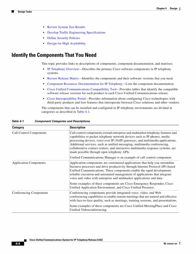
Chapter 4 Design Design Tasks
• Review System Test Results
• Develop Traffic Engineering Specifications
• Define Security Policies
• Design for High Availability
Identify the Components That You NeedThis topic provides links to descriptions of components, component documentation, and matrixes.
• IP Telephony Overview—Describes the primary Cisco software components in IP telephony systems.
• Review Release Matrix—Identifies the components and their software versions that you need.
• Component Resources Documentation for IP Telephony—Lists the component documentation.
• Cisco Unified Communications Compatibility Tool—Provides tables that identify the compatible software release versions for each product in each Cisco Unified Communications release.
• Cisco Interoperability Portal—Provides information about configuring Cisco technologies with third-party products and lists features that interoperate between Cisco solutions and other vendors.
The components that can be installed and configured in IP telephony environments are divided in categories as described in Table 4-1.
Table 4-1 Component Categories and Descriptions
Category Description
Call Control Components Call control components extend enterprise and midmarket telephony features and capabilities to packet telephony network devices such as IP phones, media processing devices, voice over IP (VoIP) gateways, and multimedia applications. Additional services, such as unified messaging, multimedia conferencing, collaborative contact centers, and interactive multimedia response systems, are made possible through open telephony APIs.
Unified Communications Manager is an example of call control component.
Application Components Application components are customized applications that help you streamline business processes and drive productivity through Internet Protocol (IP)-based Unified Communications. These components enable the rapid development, reliable execution and automated management of applications that integrate voice and video with enterprise and midmarket applications and data.
Some examples of these components are Cisco Emergency Responder, Cisco Unified Application Environment, and Cisco Unified Presence.
Conferencing Components Conferencing components provide integrated voice, video, and Web conferencing capabilities to enable remote meetings that are natural and effective with face-to-face quality, such as meetings, training sessions, and presentations.
Some examples of these components are Cisco Unified MeetingPlace and Cisco Unified Videoconferencing.
4-4Cisco Unified Communications System for IP Telephony Release 8.0(2)
OL-xxxxx-xx

Chapter 4 Design Design Tasks
Voice Mail and Unified Messaging Components
Voice mail and unified messaging components deliver powerful voice, integrated, and unified messaging options that transparently integrate with Microsoft Exchange, Lotus Domino, and Novell GroupWise. They scale to meet the needs of large, multisite organizations and offers extensive personalization options, a broad range of productivity enhancing features, and powerful migration tools, including:
• Interoperability with existing voice messaging and telephony systems
• Custom keypad mapping of the telephony interfaces
• Integrated context-sensitive help
Some examples of these components are Cisco Unity and Cisco Unity Connection.
Endpoints and Clients Components Endpoint and client components integrate the management capabilities of IP-based networks with phones, pagers, and computers and use these for signaling, voice communications, and data communications.
Some examples of these components are Cisco IP Communicator, Cisco Unified Personal Communicator, and Cisco Unified 79xx IP Phones.
Wireless and Mobility Components Wireless and mobility components provide services that enable secure, scalable, methods to real-time access to instant messaging, e-mail, and network resources. You can also access real-time simultaneous tracking of thousands of Wi-Fi devices for location-based security, high-value asset tracking, and business policy enforcement.
Some examples of these components are Cisco Unified Mobile Communicator and Aironet Wireless Access Points.
Security Components Security components are processes and technologies designed to quickly adapt to new threats to your network by using proactive, automated, real-time threat management.
Some examples of these components are Cisco Advanced Services Appliance ASA 5500 Series, Firewall Services Modules, and Cisco Intrusion Prevention System Appliance IPS-4200.
Network Management Components Network management components provide an integrated view of the entire Cisco Unified Communications system and present the current operational status of each element of the IP communications network. In addition these components provide a low-cost, reliable method of monitoring and evaluating the quality of calls and diagnosing issues.
Some examples of these components are Cisco Unified Operations Manager, Cisco Unified Service Monitor, and Cisco netManager Unified Communications.
Infrastructure Components Infrastructure components are network routers, switches, software, and other standards-based networking components that provide reliable connectivity that is more resilient and enables all the latest network services.
Some examples of these components are Cisco Series Routers, Cisco Catalyst Series Switches, and Cisco Voice Gateways.
Table 4-1 Component Categories and Descriptions (continued)
Category Description
4-5Cisco Unified Communications System for IP Telephony Release 8.0(2)
OL-xxxxx-xx
Chapter 4 Design Design Tasks
Ordering Tools
• Solution Expert is a web-based tool that assists in the design, configuration, quoting, and ordering of Unified Communications products. Solution Expert is available for Cisco sales and partner systems engineers who have Unified Communications specializations. To access Solution Expert, go to the following URL:
http://www.cisco.com/go/sx
• The Quote Builder tool is a solutions quoting application for Cisco Unified Communications products. Quote Builder is available to specialized partners and Cisco employees. With Quote Builder, users can build a system quote with design documents to aid in the implementation of the solution. Quote Builder also validates designs for common deployments. Quote Builder generates a bill of materials, a network diagram, and design guides for deployment. To access the Quote Builder tool, go to the following URL:
http://www.cisco.com/web/partners/quotebuilder/index.html
Review Tested Site ModelsCisco has developed a variety of site models as standard architectures. These models were tested and optimized for maximum efficiency and performance. You can derive your network design by choosing the deployment model that most closely matches your business and then adding the specific features and applications that meet your business needs. Review the following information:
• IP Telephony Tested Deployments and Site Models
• Purpose of Solution Tests
Review System CaveatsSystem caveats describe unexpected behavior, defects, and product limitations discovered during system-level testing of Unified Communications components
Check the latest release notes to make sure that your design has taken all system caveats into consideration. System caveats are listed under the Limitations and Restrictions section of the release notes.
Review System Test Results System test results show the scope and extent of the testing conducted for Cisco Unified Communications systems in a test environment that is modeled on real-world deployments.
Depending on the network you are designing and your specific environment, use the system test results as a guide and supplement for your own site test and turn-up plan.
For the results of testing for this Cisco Unified Communications release, see System Test Results in the Resource Library.
4-6Cisco Unified Communications System for IP Telephony Release 8.0(2)
OL-xxxxx-xx
Chapter 4 Design Design Tasks
Develop Traffic Engineering SpecificationsFor background information on various traffic analysis concepts and features that are applicable to Voice over IP (VoIP), see Traffic Analysis for Voice over IP. This document presents fundamental traffic theory, several statistical traffic models, application of traffic analysis to VoIP networks, and an end-to-end traffic analysis example.
Use the Cisco Communications Manager Capacity Tool to calculate the minimum number of active subscribers that are required to support a given installation. Inputs consist primarily of quantity and usage information on the various device types that are supported in a Cisco Unified Communications Manager system.
The following third-party traffic engineering tools are provided for your reference:
• VoIP Bandwidth Calculator
• Online Erlang Traffic Calculators
Define Security PoliciesRefer to security policies in these guides:
• Cisco Unified Communications Manager Security Guide
• Specific component documents available in the Component Resources Documentation for IP Telephony topic in the Resource Library.
Additional IP security information is included here for your reference:
• Secure Unified Communications
• Build Your Self-Defending Network
• Design Zone for Security
• Cisco Security Center
Design for High AvailabilityCisco Enterprise systems are designed for high availability. In order to achieve this, the design must include redundancy for failover and rapid recovery. For recommendations and design assistance from Cisco Advanced Services, see Navigating the Road to Five Nines.
The Unified Communications Manager plays the key role in maintaining call processing following a failure in an Enterprise environment. This topic describes the following high-availability features that are built into Unified Communications Manager:
• Unified Communications Manager Clusters
• Unified Communications Manager Redundancy Groups
• Keepalive Mechanism
Note The information in this topic applies to multiple Unified Communications Manager server clusters in a large enterprise environment and does not apply to Cisco Unified Communications Manager Business Edition. Cisco Unified Communications Manager Business Edition is a single-server solution designed for medium businesses up to a maximum of 500 employees and does not offer redundancy.
4-7Cisco Unified Communications System for IP Telephony Release 8.0(2)
OL-xxxxx-xx

Chapter 4 Design Additional Sites and Services
Unified Communications Manager Clusters
A cluster comprises a set of Unified Communications Manager servers (or nodes) that share the same database and resources. Unified Communications Manager servers can be configured to perform the following functions: database server, TFTP server, or application software server. You can dedicate a particular server to one function or combine several functions on one server, depending on the size of your network and the level of redundancy desired.
Each cluster can have only one database server (also called the first node) and usually one TFTP server (either separate or combined with another function). Cisco Systems recommends that large enterprise networks contain a dedicated Unified Communications Manager database server with other servers (called subsequent nodes) running the Unified Communications Manager application software. The Unified Communications Manager application software performs all call control, including signaling of endpoints, feature invocation, and calling restrictions. Large-scale networks typically use paired redundant application software servers, running in an active-active configuration, with endpoints evenly distributed across the two servers. The TFTP server provides configuration files for the endpoint devices and the associated firmware loads. Large enterprise networks typically use redundant TFTP servers.
Unified Communications Manager Redundancy Groups
A redundancy group comprises a prioritized list of up to three Unified Communications Manager servers. You can associate each group with one or more device pools to provide call processing redundancy. Each group must contain a primary Unified Communications Manager, and it may contain one or two backup Unified Communications Manager servers. If the primary Unified Communications Manager fails for any reason, the first backup Unified Communications Manager in the group takes control of the devices that were registered with the primary Unified Communications Manager. If you specify a second backup Unified Communications Manager for the group, it takes control of the devices if both the primary and the first backup Unified Communications Manager servers fail.
When a failed primary Unified Communications Manager comes back into service, it takes control of the group again, and the devices in that group automatically reregister with the primary Unified Communications Manager.
Keepalive Mechanism
A keepalive mechanism is an essential part of an Enterprise solution. Keepalives ensure that endpoints (typically phones and gateways) retain their communications path to a Unified Communications Manager server. Keepalives not only determine when the primary Unified Communications Manager server is no longer available, they also determine when the site has become completely isolated from a centralized call control system and must revert to some form of remote survivability capability such as Cisco Unified SRST. Keepalives avoid delays in establishing a call caused by searching for an available Unified Communications Manager server.
Additional Sites and ServicesSteps to Success is a Cisco methodology that outlines the tasks required to complete a successful customer engagement. Registered users can visit the Steps to Success resource site for Cisco Unified Communications process flows.
Cisco Unified Communications Services is a Cisco service offering that provides engineering expertise and best practices.
4-8Cisco Unified Communications System for IP Telephony Release 8.0(2)
OL-xxxxx-xx

Chapter 4 Design Additional Sites and Services
• Registered users can visit the Cisco Unified Communications Services partner site.
• Nonregistered users can visit the Cisco Unified Communications Services site.
For a solution that may fit your network design requirements, see Industry Solutions at http://www.cisco.com/web/strategy/index.html.
4-9Cisco Unified Communications System for IP Telephony Release 8.0(2)
OL-xxxxx-xx

Chapter 4 Design Additional Sites and Services
4-10Cisco Unified Communications System for IP Telephony Release 8.0(2)
OL-xxxxx-xx
Cisco Unified Com
C H A P T E R 5
ImplementIntroduction to ImplementationThe goal of implementation is to introduce the new system into the network with the least amount of disruption and the highest level of interoperability with the existing network. To minimize downtime, an essential component of this process is the implementation plan.
Before You Begin
You should understand how to implement Cisco Unified Communications. For more information, see Cisco Unified Communications Implementation.
Before you begin installing components, you should have a completed implementation plan from the detailed design. Use the equipment list and site specification from the detailed design to do the following:
• Order and stage equipment
• Perform detailed site survey
• Create site-specific installation guidelines
Your implementation plan should include:
• Deployment strategy
• Network maps and topology diagrams
• Installation and commissioning tests
• Site survey results
• List of all devices to be implemented
• Installation guidelines
• Configuration worksheets
• Test and turn-up plan
When You Are Done
All components are installed and ready to configure.
Major Tasks in This Process
• Order Equipment
• Install and Configure System Components
• Conduct User Acceptance Test
5-1munications System for IP Telephony Release 8.0(2)
Chapter 5 Implement Order Equipment
• Preparing Your Network for Troubleshooting and Recovery
Order EquipmentThis topic includes links to ordering guides and tools that you need to choose your ordering options.
Solution Expert Tool
Solution Expert is a web-based tool that assists in the design, configuration, quoting, and ordering of Cisco Unified Communications products. Solution Expert is available for Cisco sales and partner systems engineers who have Cisco Unified Communications specializations.
With the Solution Expert tool, users can generate a recommended solution based on their requirements. Users can modify the recommended configuration if desired. Solution Expert validates any changes when it presents the new solution. Solution Expert also generates a bill of materials with list pricing, a Visio diagram, and other design documentation. To access Solution Expert, go to the following URL. For an overview of how to use the tool, see the introductory PDF on the home page.
http://www.cisco.com/go/sx
Quote Builder Tool
The Quote Builder tool is a solutions quoting application for Cisco Unified Communications products. Quote Builder is available to specialized partners and Cisco employees.
With Quote Builder, users can build a system quote with design documents to aid in the implementation of the solution. Quote Builder also validates designs for common deployments. Quote Builder generates a bill of materials, a network diagram, and design guides for deployment. To access Quote Builder, go to the following URL:
http://www.cisco.com/web/partners/quotebuilder/index.html
Ordering Guides
Ordering guides for most Cisco Unified Communications products are available for Cisco partners, Cisco sales staff, and Cisco service providers.
Install and Configure System ComponentsWhen implementing a Cisco Unified Communications system, create a site-specific plan for your team. Describe what needs to be installed and configured. Your plan should list the referenced product-specific installation guides in Table 5-1.
Your plan will help you manage timelines for implementing equipment and scheduling outages. Include an installation schedule, as well as a test plan that will verify that the operation conforms to the design objectives.
5-2Cisco Unified Communications System for IP Telephony Release 8.0(2)

Chapter 5 Implement Install and Configure System Components
Preparing for Your System Installation provides guidance for the installation order of components for Cisco Unified Communications System for IP Telephony Release 8.0(2) deployment. It does not describe installation procedures for individual components. For links to the complete documentation set for each system component, see the Component Resources Documentation for IP Telephony topic on the Resource Library tab.
Performing Your System Installation
Before You Begin
See Plan and Prepare for Your System Installation on the Plan tab to plan your overall strategy.
Install IP Telephony Software Components
Once you have your installation plan and preparations in place, perform your system installation by following the guidelines and sequence in Performing Your System Installation:
• See Deployment Models for the general installation sequence for the various components in the different deployment models. For a description of deployment models, see Tested Deployments and Site Models.
• See Installing Components for more detailed installation information for each major installation strategy: single-stage and multistage system installation.
• See Related Documentation for links to component installation and upgrade documentation.
For system configuration examples, as well as other system implementation topics, see the documentation wiki (DocWiki) at http://docwiki.cisco.com/wiki/Unified_Communications_System_Implementation.
Component Installation and Configuration GuidesUsing the steps from the documents listed in Table 5-1, install or upgrade the required components for your network in the recommended order according to your site-specific implementation plan.
5-3Cisco Unified Communications System for IP Telephony Release 8.0(2)

Chapter 5 Implement Install and Configure System Components
Table 5-1 Component Installation and Configuration Documentation
Product Category Product Technology Documentation Title
Call Control Components Cisco Unified Communications Manager
• Installing Cisco Unified Communications Manager
• Replacing a Single Server or Cluster for Cisco Unified Communications Manager
• Upgrading to Cisco Communications Manager Release 8.0(1) from Release 6.1(2) and Later
• Cisco Unified Communications Manager Administration Guide
• Cisco Unified Serviceability Administration Guide
• Cisco Unified Communications Manager System Guide
• Cisco Unified Communications Manager Bulk Administration Guide
Cisco Unified Communications Manager Business Edition
• Installing Cisco Unified Communications Manager Business Edition
• Overview of Mandatory Tasks for Setting Up a Cisco Unified Communications Manager Business Edition 8.x Server
Cisco Unified Communications Manager Express
• Cisco Unified Communications Manager Express System Administrator Guide
Cisco Unified Survivable Remote Site Telephony (SRST)
• Cisco Unified SRST System Administrator Guide
• Cisco Unified SIP SRST System Administrator Guide
Cisco Unified SIP Proxy • Configuring Cisco Unified SIP Proxy Version 1.1.4 for an Enterprise Network
• Cisco Unified SIP Proxy Command Reference
Cisco Intercompany Media Engine • Cisco Intercompany Media Engine Installation and Configuration Guide
5-4Cisco Unified Communications System for IP Telephony Release 8.0(2)
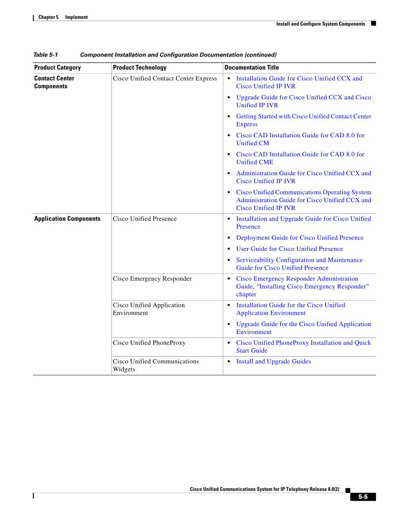
Chapter 5 Implement Install and Configure System Components
Contact Center Components
Cisco Unified Contact Center Express • Installation Guide for Cisco Unified CCX and Cisco Unified IP IVR
• Upgrade Guide for Cisco Unified CCX and Cisco Unified IP IVR
• Getting Started with Cisco Unified Contact Center Express
• Cisco CAD Installation Guide for CAD 8.0 for Unified CM
• Cisco CAD Installation Guide for CAD 8.0 for Unified CME
• Administration Guide for Cisco Unified CCX and Cisco Unified IP IVR
• Cisco Unified Communications Operating System Administration Guide for Cisco Unified CCX and Cisco Unified IP IVR
Application Components Cisco Unified Presence • Installation and Upgrade Guide for Cisco Unified Presence
• Deployment Guide for Cisco Unified Presence
• User Guide for Cisco Unified Presence
• Serviceability Configuration and Maintenance Guide for Cisco Unified Presence
Cisco Emergency Responder • Cisco Emergency Responder Administration Guide, “Installing Cisco Emergency Responder” chapter
Cisco Unified Application Environment
• Installation Guide for the Cisco Unified Application Environment
• Upgrade Guide for the Cisco Unified Application Environment
Cisco Unified PhoneProxy • Cisco Unified PhoneProxy Installation and Quick Start Guide
Cisco Unified Communications Widgets
• Install and Upgrade Guides
Table 5-1 Component Installation and Configuration Documentation (continued)
Product Category Product Technology Documentation Title
5-5Cisco Unified Communications System for IP Telephony Release 8.0(2)
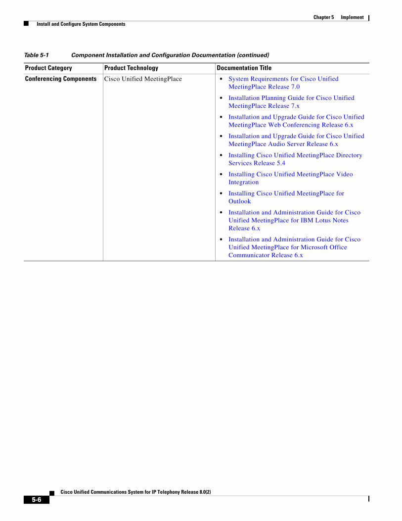
Chapter 5 Implement Install and Configure System Components
Conferencing Components Cisco Unified MeetingPlace • System Requirements for Cisco Unified MeetingPlace Release 7.0
• Installation Planning Guide for Cisco Unified MeetingPlace Release 7.x
• Installation and Upgrade Guide for Cisco Unified MeetingPlace Web Conferencing Release 6.x
• Installation and Upgrade Guide for Cisco Unified MeetingPlace Audio Server Release 6.x
• Installing Cisco Unified MeetingPlace Directory Services Release 5.4
• Installing Cisco Unified MeetingPlace Video Integration
• Installing Cisco Unified MeetingPlace for Outlook
• Installation and Administration Guide for Cisco Unified MeetingPlace for IBM Lotus Notes Release 6.x
• Installation and Administration Guide for Cisco Unified MeetingPlace for Microsoft Office Communicator Release 6.x
Table 5-1 Component Installation and Configuration Documentation (continued)
Product Category Product Technology Documentation Title
5-6Cisco Unified Communications System for IP Telephony Release 8.0(2)

Chapter 5 Implement Install and Configure System Components
Voice Mail and Messaging Components
Cisco Unity • Supported Hardware and Software, and Support Policies for Cisco Unity Release 7.x
• Use the Installation Guide That Matches the Cisco Unity 7.x Configuration
• Installation Guide for Cisco Unity Release 5.x in a Unified Messaging Configuration with Microsoft Exchange (With Failover Configured)
• Installation Guide for Cisco Unity Release 5.x in a Unified Messaging Configuration with Microsoft Exchange (Without Failover)
• Installation Guide for Cisco Unity Release 5.x in a Voice Messaging Configuration with Microsoft Exchange (With Failover Configured)
• Installation Guide for Cisco Unity Release 5.x in a Voice Messaging Configuration with Microsoft Exchange (Without Failover)
• Reconfiguration and Upgrade Guide for Cisco Unity Release 5.x (With Microsoft Exchange)
Cisco Unity Connection • Installation Guide for Cisco Unity Connection Release 7.x
• Supported Hardware and Software, and Support Policies for Cisco Unity Connection 2.x
• System Requirements for Cisco Unity Connection/ System Requirements for Cisco Unity Connection in Cisco Unified CMBE
• System Requirements for Cisco Unity Connection Release 7.0
Cisco Unity Express • Cisco Unity Express 3.1 Installation and Upgrade Guide
Cisco Unified Survivable Remote Site Voicemail
• Installation and Administration Guide for Cisco Unified SRSV-CUE
Cisco Unified Messaging Gateway • Installation and Upgrade Guide for Cisco Unified Messaging Gateway
Table 5-1 Component Installation and Configuration Documentation (continued)
Product Category Product Technology Documentation Title
5-7Cisco Unified Communications System for IP Telephony Release 8.0(2)

Chapter 5 Implement Install and Configure System Components
Endpoints and Clients Components
Cisco Unified 39xxx SIP Phones • Cisco Unified IP Phone 3900 Series Install and Upgrade Guides
• Cisco Unified IP Phone 3900 Series End-User Guides
• Cisco Unified IP Phone 3900 Series Maintain and Operate Guides
Cisco Unified 69xx IP Phones • Cisco Unified IP Phone 6900 Series End-User Guides
• Cisco Unified IP Phone 6900 Series Maintain and Operate Guides
Cisco Unified 79xx IP Phones • Cisco Unified IP Phone 7900 Series Install and Upgrade Guides
• Cisco Unified IP Phone 7900 Series End-User Guides
• Cisco Unified IP Phone 7900 Series Maintain and Operate Guides
Cisco Unified 89xx IP Phones • Cisco Unified IP Phone 8900 Series Install and Upgrade Guides
• Cisco Unified IP Phone 8900 Series End-User Guides
• Cisco Unified IP Phone 8900 Series Maintain and Operate Guides
Cisco Unified 99xx IP Phones • Cisco Unified IP Phone 9900 Series Install and Upgrade Guides
• Cisco Unified IP Phone 9900 Series End-User Guides
• Cisco Unified IP Phone 9900 Series Maintain and Operate Guides
Cisco IP Communicator • Cisco IP Communicator, Data Sheet
• Deploying and Updating Cisco IP Communicator
Cisco Unified Personal Communicator • Deployment Guide for Cisco Unified Presence
Cisco UC Integration™ for Microsoft
Office Communicator
• http://www.cisco.com/en/US/products/ps10317/tsd_products_support_series_home.html
Cisco UC Integration™ for WebEx
Connect
• http://www.cisco.com/en/US/products/ps10627/tsd_products_support_series_home.html
Cisco Unified Video Advantage • Installation and Troubleshooting Guide for Cisco Unified Video Advantage Release 2.1
Table 5-1 Component Installation and Configuration Documentation (continued)
Product Category Product Technology Documentation Title
5-8Cisco Unified Communications System for IP Telephony Release 8.0(2)
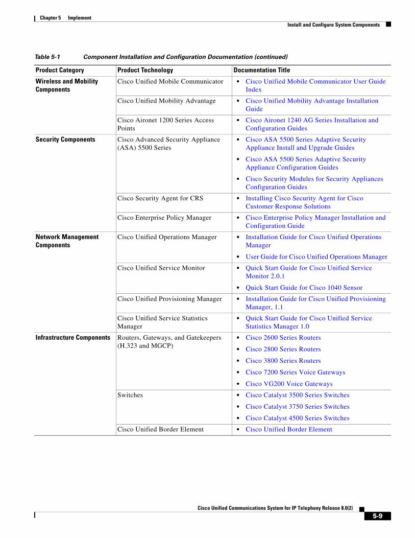
Chapter 5 Implement Install and Configure System Components
Wireless and Mobility Components
Cisco Unified Mobile Communicator • Cisco Unified Mobile Communicator User Guide Index
Cisco Unified Mobility Advantage • Cisco Unified Mobility Advantage Installation Guide
Cisco Aironet 1200 Series Access Points
• Cisco Aironet 1240 AG Series Installation and Configuration Guides
Security Components Cisco Advanced Security Appliance (ASA) 5500 Series
• Cisco ASA 5500 Series Adaptive Security Appliance Install and Upgrade Guides
• Cisco ASA 5500 Series Adaptive Security Appliance Configuration Guides
• Cisco Security Modules for Security Appliances Configuration Guides
Cisco Security Agent for CRS • Installing Cisco Security Agent for Cisco Customer Response Solutions
Cisco Enterprise Policy Manager • Cisco Enterprise Policy Manager Installation and Configuration Guide
Network Management Components
Cisco Unified Operations Manager • Installation Guide for Cisco Unified Operations Manager
• User Guide for Cisco Unified Operations Manager
Cisco Unified Service Monitor • Quick Start Guide for Cisco Unified Service Monitor 2.0.1
• Quick Start Guide for Cisco 1040 Sensor
Cisco Unified Provisioning Manager • Installation Guide for Cisco Unified Provisioning Manager, 1.1
Cisco Unified Service Statistics Manager
• Quick Start Guide for Cisco Unified Service Statistics Manager 1.0
Infrastructure Components Routers, Gateways, and Gatekeepers (H.323 and MGCP)
• Cisco 2600 Series Routers
• Cisco 2800 Series Routers
• Cisco 3800 Series Routers
• Cisco 7200 Series Voice Gateways
• Cisco VG200 Voice Gateways
Switches • Cisco Catalyst 3500 Series Switches
• Cisco Catalyst 3750 Series Switches
• Cisco Catalyst 4500 Series Switches
Cisco Unified Border Element • Cisco Unified Border Element
Table 5-1 Component Installation and Configuration Documentation (continued)
Product Category Product Technology Documentation Title
5-9Cisco Unified Communications System for IP Telephony Release 8.0(2)

Chapter 5 Implement Introduction to Troubleshooting
Software Versions and System CaveatsFor specific information on the product software versions used, system limitations, and known caveats, see the System Release Notes for IP Telephony: Cisco Unified Communications System, Release 8.0(2).
Configuration ExamplesSample configuration commands for infrastructure components that are involved in the call flows are in downloadable zip files for all test bed components in Configuration Command Files for IP Telephony in the Resource Library.
System-level configuration examples are available on the Cisco DocWiki at http://docwiki.cisco.com/wiki/Category:IP_Telephony_System_Configurations.
Introduction to TroubleshootingThis topic describes how to develop a system-level troubleshooting methodology as you install and configure a Cisco Unified Communications network for the first time. It also provides recommendations for preparing and documenting the network that may assist you in diagnosing and isolating problems when they occur. This topic contains the following sections:
• System Troubleshooting Methodology
• Preparing Your Network for Troubleshooting and Recovery
System Troubleshooting MethodologyThe Implementation phase of your network deployment is an excellent time to develop a methodology for troubleshooting the network as a whole. Troubleshooting networking equipment at a system level requires solid detective skills. When a problem occurs, the list of potential suspects is long. You must collect detailed information and systematically narrow the list of potential causes to determine the root problem. This topic does not provide step-by-instructions for resolving problems that occur during network installation. Instead, this topic describes sound methods for troubleshooting your network using the following general steps:
1. Gather Information on the Problem.
2. Isolate Point(s) of Failure.
3. Apply Tools to Determine the Problem’s Root Cause.
Gather Information on the Problem
Problems are typically discovered and reported by one of the following types of users:
• External users trying to reach employees within your company
• External customers dialing into a call center to order products, obtain customer service, and so forth.
• Internal agents receiving incoming calls from a call queue or initiating outbound collection calls to customers.
• Internal users using administrative phones to call employees in other company locations or PSTN destinations, and perform basic actions such as call transfers and dialing into conferences.
5-10Cisco Unified Communications System for IP Telephony Release 8.0(2)
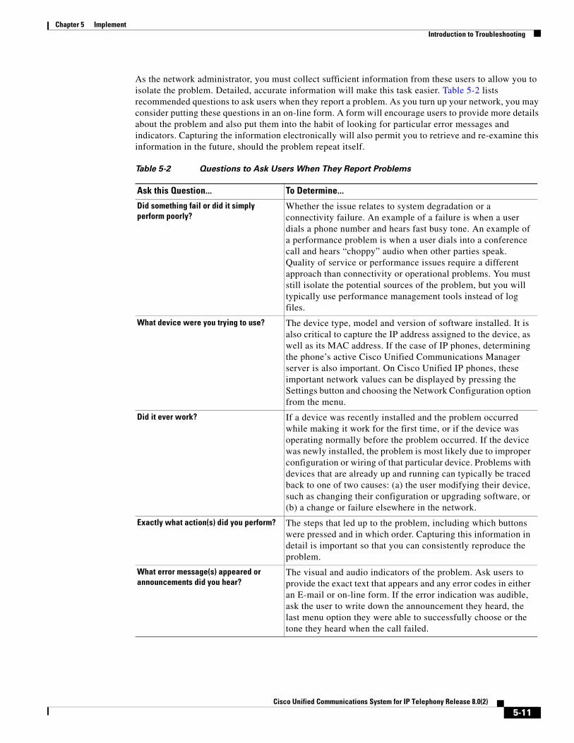
Chapter 5 Implement Introduction to Troubleshooting
As the network administrator, you must collect sufficient information from these users to allow you to isolate the problem. Detailed, accurate information will make this task easier. Table 5-2 lists recommended questions to ask users when they report a problem. As you turn up your network, you may consider putting these questions in an on-line form. A form will encourage users to provide more details about the problem and also put them into the habit of looking for particular error messages and indicators. Capturing the information electronically will also permit you to retrieve and re-examine this information in the future, should the problem repeat itself.
Table 5-2 Questions to Ask Users When They Report Problems
Ask this Question... To Determine...
Did something fail or did it simply perform poorly?
Whether the issue relates to system degradation or a connectivity failure. An example of a failure is when a user dials a phone number and hears fast busy tone. An example of a performance problem is when a user dials into a conference call and hears “choppy” audio when other parties speak. Quality of service or performance issues require a different approach than connectivity or operational problems. You must still isolate the potential sources of the problem, but you will typically use performance management tools instead of log files.
What device were you trying to use? The device type, model and version of software installed. It is also critical to capture the IP address assigned to the device, as well as its MAC address. If the case of IP phones, determining the phone’s active Cisco Unified Communications Manager server is also important. On Cisco Unified IP phones, these important network values can be displayed by pressing the Settings button and choosing the Network Configuration option from the menu.
Did it ever work? If a device was recently installed and the problem occurred while making it work for the first time, or if the device was operating normally before the problem occurred. If the device was newly installed, the problem is most likely due to improper configuration or wiring of that particular device. Problems with devices that are already up and running can typically be traced back to one of two causes: (a) the user modifying their device, such as changing their configuration or upgrading software, or (b) a change or failure elsewhere in the network.
Exactly what action(s) did you perform? The steps that led up to the problem, including which buttons were pressed and in which order. Capturing this information in detail is important so that you can consistently reproduce the problem.
What error message(s) appeared or announcements did you hear?
The visual and audio indicators of the problem. Ask users to provide the exact text that appears and any error codes in either an E-mail or on-line form. If the error indication was audible, ask the user to write down the announcement they heard, the last menu option they were able to successfully choose or the tone they heard when the call failed.
5-11Cisco Unified Communications System for IP Telephony Release 8.0(2)
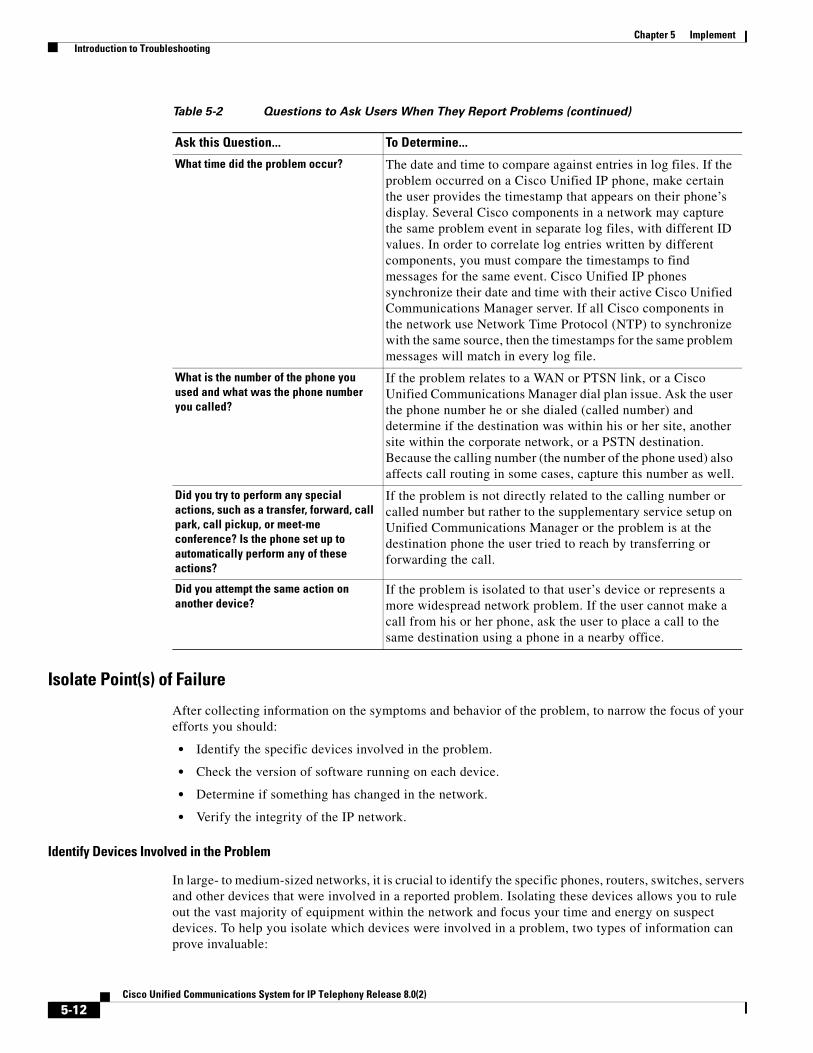
Chapter 5 Implement Introduction to Troubleshooting
Isolate Point(s) of Failure
After collecting information on the symptoms and behavior of the problem, to narrow the focus of your efforts you should:
• Identify the specific devices involved in the problem.
• Check the version of software running on each device.
• Determine if something has changed in the network.
• Verify the integrity of the IP network.
Identify Devices Involved in the Problem
In large- to medium-sized networks, it is crucial to identify the specific phones, routers, switches, servers and other devices that were involved in a reported problem. Isolating these devices allows you to rule out the vast majority of equipment within the network and focus your time and energy on suspect devices. To help you isolate which devices were involved in a problem, two types of information can prove invaluable:
What time did the problem occur? The date and time to compare against entries in log files. If the problem occurred on a Cisco Unified IP phone, make certain the user provides the timestamp that appears on their phone’s display. Several Cisco components in a network may capture the same problem event in separate log files, with different ID values. In order to correlate log entries written by different components, you must compare the timestamps to find messages for the same event. Cisco Unified IP phones synchronize their date and time with their active Cisco Unified Communications Manager server. If all Cisco components in the network use Network Time Protocol (NTP) to synchronize with the same source, then the timestamps for the same problem messages will match in every log file.
What is the number of the phone you used and what was the phone number you called?
If the problem relates to a WAN or PTSN link, or a Cisco Unified Communications Manager dial plan issue. Ask the user the phone number he or she dialed (called number) and determine if the destination was within his or her site, another site within the corporate network, or a PSTN destination. Because the calling number (the number of the phone used) also affects call routing in some cases, capture this number as well.
Did you try to perform any special actions, such as a transfer, forward, call park, call pickup, or meet-me conference? Is the phone set up to automatically perform any of these actions?
If the problem is not directly related to the calling number or called number but rather to the supplementary service setup on Unified Communications Manager or the problem is at the destination phone the user tried to reach by transferring or forwarding the call.
Did you attempt the same action on another device?
If the problem is isolated to that user’s device or represents a more widespread network problem. If the user cannot make a call from his or her phone, ask the user to place a call to the same destination using a phone in a nearby office.
Table 5-2 Questions to Ask Users When They Report Problems (continued)
Ask this Question... To Determine...
5-12Cisco Unified Communications System for IP Telephony Release 8.0(2)
Chapter 5 Implement Introduction to Troubleshooting
• Network topology diagrams: It is strongly recommended that you have one or more diagrams that show the arrangement of all Cisco Unified Communications products in your network. These diagrams illustrate how these devices are connected and also capture each device’s IP address and name (you may want to also have a spreadsheet or database of the latter information). This information can help you visualize the situation and focus on the devices that may be contributing to the reported problem. See Network Topology Diagrams for recommendations on how to prepare these diagrams.
• Call flow diagrams: Cisco equipment, including Unified Communications Manager servers, typically provide detailed debug and call trace log files. To interpret these log files, however, it is useful to understand the signaling that occurs between devices as calls are set up and disconnected. Using the network topology and call flow diagrams in conjunction with the log files, you can trace how far a call progressed before it failed and identify which device reported the problem. Examples of using call flow diagrams for problem isolation are shown in Troubleshooting Daily Operations.
Check Software Release Versions for Compatibility
After you have identified which devices may be involved in the problem, verify that the version of software running on each device is compatible with the software running on every other device. As part of Cisco Unified Communications Release 8.0(2) verification, Cisco Systems has performed interoperability and load testing on simulated network environments running specific software versions. The System Release Notes for IP Telephony: Cisco Unified Communications System, Release 8.0(2) lists the combination of software releases that were tested.
However, if the combination of releases installed in your network does not match the values in the Release Matrix, it does not necessarily mean the combination is invalid. To check interoperability for a specific device and software release, locate and review its Release Notes. Release Notes contain up-to-date information on compatibility between the product and various releases of other products. This document also describes open caveats, known issues that may cause unexpected behavior. Before beginning extensive troubleshooting work, examine the Release Notes to determine if you are experiencing a known problem that has an available workaround.
Tip The Bug Toolkit requires that you are a Cisco partner or a registered Cisco.com user with a Cisco service contract. Using the Bug Toolkit, you can find caveats for any release. To access the Bug Toolkit, go to the http://tools.cisco.com/Support/BugToolKit/ .
Determine if Network Changes Have Occurred
Before focusing on the particular device or site where the problem occurred, it may be useful to determine if a change was made to surrounding devices. If something has been added, reconfigured or removed from elsewhere in the network, that change may be the source of the problem. It is recommended that you track changes to the network such as:
• New phones added
• Modifications to Cisco Unified Communications Manager call routing settings, such as new directory numbers, route patterns and dial rules to support new sites or devices
• Changes to port configurations on switches, routers or gateways (new equipment, wiring changes or new port activation)
• Changes to IP addressing schemes (such as adding new subnets) that may have affected route tables
5-13Cisco Unified Communications System for IP Telephony Release 8.0(2)

Chapter 5 Implement Introduction to Troubleshooting
Verify the IP Network Integrity
Always remember that Cisco Unified Communications equipment relies on a backbone IP network. Many connectivity problems are not caused by configuration errors or operational failures on Cisco devices, but rather by the IP network that interconnects them. Problems such as poor voice quality are typically due to IP network congestion, while call failures between locations may be the result of network outages due to disconnected cables or improperly configured IP route tables.
Before assuming that call processing problems result from Cisco Unified Communications devices themselves, check the integrity of the backbone IP network. Keep the OSI model in mind as you perform these checks. Start from the bottom, at the physical layer, by checking that end-to-end cabling. Then verify the status of Layer 2 switches, looking for any port errors. Move from there to confirm that the Layer 3 routers are running and contain correct routing tables. Continue up the OSI stack to Layer 7, the application layer. To resolve problems occurring at the top levels of the stack, a protocol analyzer (or “sniffer”) may be useful. You can use sniffer to examine the IP traffic passing between devices and also decode the packets. Sniffers are particularly useful for troubleshooting errors between devices that communicate using Media Gateway Control Protocol (MGCP) or Session Initiation Protocol (SIP).
Apply Tools to Determine the Problem’s Root Cause
After you have eliminated the IP network as the source of the problem and you have isolated the specific Cisco Unified Communications components involved, you can start applying the many diagnostic tools provided by Cisco components.
Table 5-3 lists the diagnostic tools and supporting troubleshooting documentation available for most components in an IP telephony network. Note that this summary table is provided for reference only. The procedures in Troubleshooting Daily Operations specify when to use each tool and provide links to the troubleshooting instructions in each component’s documentation where appropriate.
5-14Cisco Unified Communications System for IP Telephony Release 8.0(2)
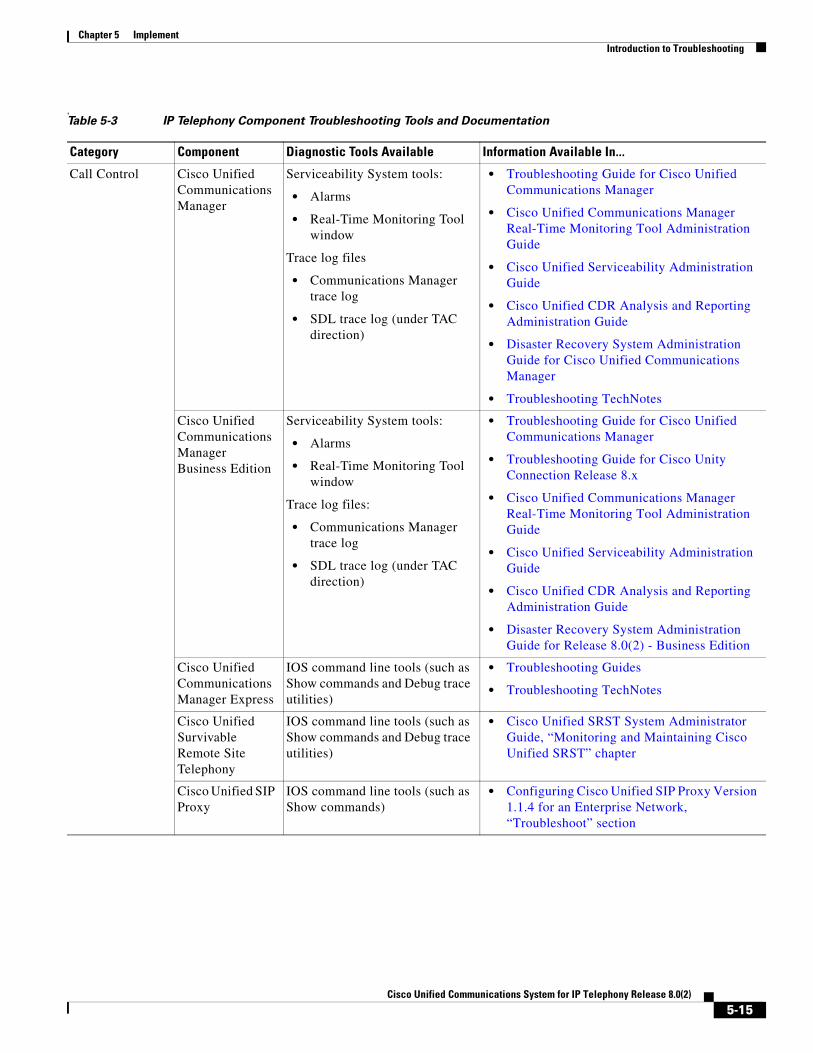
Chapter 5 Implement Introduction to Troubleshooting
, Table 5-3 IP Telephony Component Troubleshooting Tools and Documentation
Category Component Diagnostic Tools Available Information Available In...
Call Control Cisco Unified Communications Manager
Serviceability System tools:
• Alarms
• Real-Time Monitoring Tool window
Trace log files
• Communications Manager trace log
• SDL trace log (under TAC direction)
• Troubleshooting Guide for Cisco Unified Communications Manager
• Cisco Unified Communications Manager Real-Time Monitoring Tool Administration Guide
• Cisco Unified Serviceability Administration Guide
• Cisco Unified CDR Analysis and Reporting Administration Guide
• Disaster Recovery System Administration Guide for Cisco Unified Communications Manager
• Troubleshooting TechNotes
Cisco Unified Communications Manager Business Edition
Serviceability System tools:
• Alarms
• Real-Time Monitoring Tool window
Trace log files:
• Communications Manager trace log
• SDL trace log (under TAC direction)
• Troubleshooting Guide for Cisco Unified Communications Manager
• Troubleshooting Guide for Cisco Unity Connection Release 8.x
• Cisco Unified Communications Manager Real-Time Monitoring Tool Administration Guide
• Cisco Unified Serviceability Administration Guide
• Cisco Unified CDR Analysis and Reporting Administration Guide
• Disaster Recovery System Administration Guide for Release 8.0(2) - Business Edition
Cisco Unified Communications Manager Express
IOS command line tools (such as Show commands and Debug trace utilities)
• Troubleshooting Guides
• Troubleshooting TechNotes
Cisco Unified Survivable Remote Site Telephony
IOS command line tools (such as Show commands and Debug trace utilities)
• Cisco Unified SRST System Administrator Guide, “Monitoring and Maintaining Cisco Unified SRST” chapter
Cisco Unified SIP Proxy
IOS command line tools (such as Show commands)
• Configuring Cisco Unified SIP Proxy Version 1.1.4 for an Enterprise Network, “Troubleshoot” section
5-15Cisco Unified Communications System for IP Telephony Release 8.0(2)

Chapter 5 Implement Introduction to Troubleshooting
Contact Center Cisco Unified Contact Center Express
Log files
Alarms
• Cisco Unified Real-Time Monitoring Tool Administration Guide for Cisco Unified CCX and Cisco Unified IP IVR
• Cisco Unified Serviceability Administration Guide
• Disaster Recovery System Administration Guide for Cisco Unified CCX and Cisco Unified IP IVR
• Serviceability Administration Guide for Cisco Unified CCX and Cisco Unified IP IVR
• Cisco CAD Troubleshooting Guide for Cisco Unified Communications Manager
• Cisco CAD Troubleshooting Guide for Cisco Unified Communications Manager Express
• Troubleshooting TechNotes
Table 5-3 IP Telephony Component Troubleshooting Tools and Documentation (continued)
Category Component Diagnostic Tools Available Information Available In...
5-16Cisco Unified Communications System for IP Telephony Release 8.0(2)

Chapter 5 Implement Introduction to Troubleshooting
Applications Cisco Unified Presence
System Configuration Troubleshooter
Presence troubleshooter
Microsoft Office Configuration Troubleshooter
Trace log files
Alarms
• Serviceability Configuration and Maintenance Guide for Cisco Unified Presence
• Instant Messaging Compliance Guide for Cisco Unified Presence, “IM Compliance Serviceability and Troubleshooting” chapter
• Integration Guide for Configuring Cisco Unified Presence for Interdomain Federation, “Troubleshooting” chapters
• Integration Note for Configuring Cisco Unified Presence with Microsoft Exchange, Troubleshooting Tips
• Integration Note for Configuring Cisco Unified Presence with Microsoft OCS for Microsoft Office Communicator Call Control, Troubleshooting Tips
• Disaster Recovery System Administration Guide for Cisco Unified Presence
• Troubleshooting TechNotes
Cisco Emergency Responder
E-mail alerts sent to administrator
ERL Debug tool
Cisco ER Admin Utility tool
Call history logs
SYSLOG collector tool that generates trace and debug files
Windows Event Viewer
• Cisco Emergency Responder Administration Guide, “Troubleshooting Cisco Emergency Responder” chapter
• Cisco Emergency Responder Troubleshooting Guide
Cisco Unified Application Environment
AppServer log files • Administration Guide for the Cisco Unified Application Environment, “FAQs and Troubleshooting” chapter
Conferencing Cisco Unified MeetingPlace
Log files:
• Gateway SIM event log
• Error log
gwcptrace CLI command
• Administration Documentation for Cisco Unified MeetingPlace, “Troubleshooting” section
• Troubleshooting TechNotes
Table 5-3 IP Telephony Component Troubleshooting Tools and Documentation (continued)
Category Component Diagnostic Tools Available Information Available In...
5-17Cisco Unified Communications System for IP Telephony Release 8.0(2)

Chapter 5 Implement Introduction to Troubleshooting
Voice Mail and Unified Messaging
Cisco Unity Event log
Cisco Unity Diagnostic Tool (UDT):
• Macro trace logs
• Micro trace logs
Voice Connector trace logs
Tools Depot utilities:
• Integration Monitor
• Call Viewer
• Port Status Monitor
Dialogic tools (for systems equipped with Dialogic voice cards only):
• TSP trace logs
• Universal Dialogic Diagnostics Utility
Dr. Watson logs for underlying Windows server platform
• Troubleshooting Guide for Cisco Unity Release 8.x (With Microsoft Exchange)
• Troubleshooting TechNotes
Cisco Unity Connection
Serviceability System tools:
• Alarms
• Real-Time Monitoring Tool window
Cisco Unity Diagnostic Tool (UDT):
• Macro trace logs
• Micro trace logs
CuVrt service verbose logging
• Troubleshooting Guide for Cisco Unity Connection
• Cisco Unified Serviceability Administration Guide
• Cisco Unified Real-Time Monitoring Tool Administration Guide
• Troubleshooting TechNotes
Cisco Unity Express
CLI commands for status checking and performance monitoring
SNMP alarms/events
• Cisco Unity Express Voice-Mail and Auto-Attendant CLI Administrator Guide, “Troubleshooting” chapter
• Troubleshooting TechNotes
Cisco Unified Messaging Gateway
Network connectivity tests
Log files
• CLI Administrator Guide for Cisco Unified Messaging Gateway (Cisco UMG), “Troubleshooting Tasks” chapter
• GUI Administrator Guide for Cisco Unified Messaging Gateway (Cisco UMG), “Troubleshooting” chapter
Table 5-3 IP Telephony Component Troubleshooting Tools and Documentation (continued)
Category Component Diagnostic Tools Available Information Available In...
5-18Cisco Unified Communications System for IP Telephony Release 8.0(2)

Chapter 5 Implement Introduction to Troubleshooting
Endpoints and Clients
Cisco Unified IP Phones
Network configuration, status and phone model information on Settings menu
• End-User Guides
– Cisco Unified IP Phone 3900 Series
– Cisco Unified IP Phone 6900 Series
– Cisco Unified IP Phone 7900 Series
– Cisco Unified IP Phone 8900 Series
– Cisco Unified IP Phone 9900 Series
• Cisco Unified IP Phone Administration Guides for Cisco Unified Communications Manager, “Troubleshooting and Maintenance” chapters
– Cisco Unified IP Phone 3900 Series
– Cisco Unified IP Phone 6900 Series
– Cisco Unified IP Phone 7900 Series
– Cisco Unified IP Phone 8900 Series
– Cisco Unified IP Phone 9900 Series
• Error Message Decoder
• Output Interpreter
• Troubleshooting TechNotes
– Cisco Unified IP Phone 7900 Series
Cisco IP Communicator
Quality Report Tool (QRT)
Error Reporting Tool
• Administration Guide for Cisco IP Communicator, “Troubleshooting Cisco IP Communicator” chapter
• User Guide for Cisco IP Communicator, “Troubleshooting Cisco IP Communicator” chapter
• Troubleshooting TechNotes
Cisco Unified Personal Communicator
Problem Reporting Tool/Assistant
Trace logs
• Troubleshooting Guide for Cisco Unified Personal Communicator
• User Guide for Cisco Unified Personal Communicator for Windows, “Troubleshooting Cisco Unified Personal Communicator” chapter for Windows version
• User Guide for Cisco Unified Personal Communicator for Macintosh, “Troubleshooting Cisco Unified Personal Communicator” chapter for Macintosh version
• Troubleshooting TechNotes
Table 5-3 IP Telephony Component Troubleshooting Tools and Documentation (continued)
Category Component Diagnostic Tools Available Information Available In...
5-19Cisco Unified Communications System for IP Telephony Release 8.0(2)

Chapter 5 Implement Introduction to Troubleshooting
Cisco Unified Video Advantage
Diagnostics Tool
AutoUpdate Status Viewer
CAST Viewer
CDP Viewer
Trace Tool
Error Reporting Tool
• Installation and Troubleshooting Guide for Cisco Unified Video Advantage, “Troubleshooting Cisco Unified Video Advantage” chapter
• Cisco Unified Video Advantage User Guide, “Troubleshooting Cisco Unified Video Advantage” chapter
• Troubleshooting TechNotes
Wireless and Mobility
Cisco Aironet 1200 Access Point
LEDs
Carrier busy test
Ping/link test
• Cisco Aironet 1200 Series Access Point Hardware Installation Guide, “Troubleshooting” chapters
• Cisco IOS Software Configuration Guide for Cisco Aironet Access Points, “Troubleshooting” chapter
• Troubleshooting TechNotes
Cisco Unified Mobility Advantage
Log files • Troubleshooting Cisco Unified Mobility Advantage
Cisco Unified Mobile Communicator
Call Logs • User Guide for Cisco Unified Mobile Communicator for Windows Mobile Phones, “Troubleshooting Cisco Unified Mobile Communicator for Windows Mobile Phones” chapter
• Installation and User Guide for Cisco Unified Mobile Communicator for Nokia Phones, “Troubleshooting and FAQ” chapter
• Installation and User Guide for Cisco Mobile for BlackBerry Devices, ““Troubleshooting and FAQ” chapter
Security Cisco ASA 5500 Series Adaptive Security Appliances
IOS command line tools (such as Show commands)
• Cisco ASA 5500 Series Configuration Guide using the CLI, “Troubleshooting” section
• Error Message Decoder
• Output Interpreter
• Troubleshooting TechNotes
Table 5-3 IP Telephony Component Troubleshooting Tools and Documentation (continued)
Category Component Diagnostic Tools Available Information Available In...
5-20Cisco Unified Communications System for IP Telephony Release 8.0(2)

Chapter 5 Implement Introduction to Troubleshooting
Network Management
Cisco Unified Operations Manager
Alarms and events appearing in Dashboard displays
Phone status tests
Synthetic test
Node-to-node tests
• User Guide for Cisco Unified Operations Manager, “Administering Operations Manager” chapter
Cisco Unified Service Monitor
Diagnostic reports on sensors and CVTQ
• Frequently Asked Questions and Troubleshooting Scenarios for Cisco Unified Service Monitor
• User Guide for Cisco Unified Service Monitor, “Administering the System and Managing Data” chapter
Cisco Unified Service Statistics Manager
• User Guide for Cisco Unified Service Statistics Manager, “Using the SSM Administration Console” chapter
Cisco Unified Provisioning Manager
• User Guide for Cisco Unified Provisioning Manager, “Administering Infrastructure” chapter
Communications Infrastructure
Cisco 1800 Series Integrated Services Router
IOS command line tools (such as Show commands and Debug trace utilities)
• Cisco 1800 Series Software Configuration Guide, “Troubleshooting and Maintenance” chapters
• Troubleshooting TechNotes
Cisco 2800 Series Integrated Services Router
IOS command line tools (such as Show commands and Debug trace utilities)
• Cisco 2800 Series Software Configuration Guide, “Using the ROM Monitor” chapter
• Troubleshooting TechNotes
Cisco 2900 Series Integrated Services Router
IOS command line tools (such as Show commands and Debug trace utilities)
• Cisco 3900 Series, 2900 Series, and 1900 Series Software Configuration Guide, “Using ROM Monitor” chapter
Cisco 3800 Series Integrated Services Router
IOS command line tools (such as Show commands and Debug trace utilities)
• Cisco 3800 Series Software Configuration Guide, “Troubleshooting and Maintenance” chapters
• Troubleshooting TechNotes
Cisco 3900 Series Integrated Services Router
IOS command line tools (such as Show commands and Debug trace utilities)
• Cisco 3900 Series, 2900 Series, and 1900 Series Software Configuration Guide, “Using ROM Monitor” chapter
Cisco Catalyst 3550 Access Switch
IOS command line tools (such as Show commands and Debug trace utilities)
• Catalyst 3550 Multilayer Switch Software Configuration Guide, “Troubleshooting” chapter
• Error Message Decoder
• Output Interpreter
• Troubleshooting Tech Notes
Table 5-3 IP Telephony Component Troubleshooting Tools and Documentation (continued)
Category Component Diagnostic Tools Available Information Available In...
5-21Cisco Unified Communications System for IP Telephony Release 8.0(2)
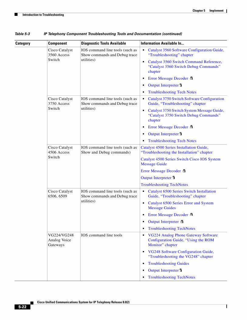
Chapter 5 Implement Introduction to Troubleshooting
Cisco Catalyst 3560 Access Switch
IOS command line tools (such as Show commands and Debug trace utilities)
• Catalyst 3560 Software Configuration Guide, “Troubleshooting” chapter
• Catalyst 3560 Switch Command Reference, “Catalyst 3560 Switch Debug Commands” chapter
• Error Message Decoder
• Output Interpreter
• Troubleshooting Tech Notes
Cisco Catalyst 3750 Access Switch
IOS command line tools (such as Show commands and Debug trace utilities)
• Catalyst 3750 Switch Software Configuration Guide, “Troubleshooting” chapter
• Catalyst 3750 Switch System Message Guide, “Catalyst 3750 Switch Debug Commands” chapter
• Error Message Decoder
• Output Interpreter
• Troubleshooting Tech Notes
Cisco Catalyst 4506 Access Switch
IOS command line tools (such as Show and Debug commands)
Catalyst 4500 Series Installation Guide, “Troubleshooting the Installation” chapter
Catalyst 4500 Series Switch Cisco IOS System Message Guide
Error Message Decoder
Output Interpreter
Troubleshooting TechNotes
Cisco Catalyst 6506, 6509
IOS command line tools (such as Show commands and Debug trace utilities)
• Catalyst 6500 Series Switch Installation Guide, “Troubleshooting” chapter
• Catalyst 6500 Series Error and System Message Guides
• Error Message Decoder
• Output Interpreter
• Troubleshooting TechNotes
VG224/VG248 Analog Voice Gateways
IOS command line tools • VG224 Analog Phone Gateway Software Configuration Guide, “Using the ROM Monitor” chapter
• VG248 Software Configuration Guide, “Troubleshooting the VG248” chapter
• Troubleshooting Guides
• Output Interpreter
• Troubleshooting TechNotes
Table 5-3 IP Telephony Component Troubleshooting Tools and Documentation (continued)
Category Component Diagnostic Tools Available Information Available In...
5-22Cisco Unified Communications System for IP Telephony Release 8.0(2)

Chapter 5 Implement Introduction to Troubleshooting
Preparing Your Network for Troubleshooting and RecoveryBefore your network becomes operational, you can take several proactive steps to make troubleshooting easier, including:
• Produce network topology diagrams to help you isolate potential sources of problems.
• Synchronize the date and time on all servers.
• Set trace/logging levels on key devices so that diagnostic information is available when problems occur.
Network Topology Diagrams
One of the first lines of defense is possessing current topology information. One of the most important pieces of topology information is a detailed network diagram (usually created using Microsoft Visio or a similar application). At a minimum, your network topology diagrams should include the following information:
• The name assigned to each major device (typically the DNS name)
• IP addresses for all devices in the network
– Addresses for each router, core and access switch
– Addresses for all telephony and application servers, including the IP address for each server in a Cisco Unified Communications Manager cluster
– DHCP address range for addresses assigned to endpoints such as IP phones and agent workstations
• Phone extension number ranges assigned to sets of agents or users, as well as the main inbound dial-up numbers for each location. This information is useful in resolving dial plan configuration errors.
• WAN IP and PSTN links between sites.
This information is critical for isolating which components are involved in a particular problem. For medium- to large-sized networks, you may want to take a “layered” approach in your diagrams. Create a high-level diagram that illustrates the overall physical layout of your network, including all sites and the links between them. Then for each site create additional diagrams that show detailed addressing information, port numbers and dial plan configurations.
Tip Frequent adds, changes and upgrades to your network can quickly make these diagrams out-of-date. Inaccurate diagrams slow down the troubleshooting process and may lead to misdiagnosing the problem. Remember to keep these diagrams as current as possible.
Figure 5-1 shows a typical high-level topology diagram for a medium-sized enterprise IP telephony network. Note that only device names and IP addresses are listed in the diagram.
5-23Cisco Unified Communications System for IP Telephony Release 8.0(2)

Chapter 5 Implement Introduction to Troubleshooting
Figure 5-1 IP Telephony Network Topology Diagram Example
Synchronizing Server Date and Time
The best resources for diagnosing problems within your network are the debug and trace log files produced by individual Cisco devices. Tracing can be enabled on multiple devices and the log file output compared to isolate problems. In order to correlate messages for the same activity in different log files, you must compare the message timestamps and the source device MAC and IP addresses (there is no universal call ID value shared between Cisco devices). You should synchronize every device to the same date and time source so that the timestamps match. To accomplish this synchronization, set each device to obtain its date and time from the same Network Time Protocol (NTP) source.
For Cisco IOS-based devices (switches, routers or voice gateways), you can configure each device to act as a NTP client and periodically poll a master NTP source using the following command:
ntp server ip-address [version number] [key keyid] [source interface] [prefer]
Additional IOS commands are available to establish a device as a NTP peer (operating as the master source for other devices), as well as setting up NTP broadcasting instead of polling. See the Cisco IOS Configuration Fundamentals Command Reference for details on these IOS commands.
Unified CMSub Node 110.4.3.10
PBX
Unified MeetingPlace Servers
Access Switch AS2
10.4.5.3
Sales Phones(32 phones)
Access Switch AS3
10.4.5.4
Marketing Phones(17 phones)
HR/Administration Phones (25 phones)
Unified CMSub Node 210.4.4.11
HEADQUARTERS – San Jose
Unified CMFirst Node10.3.1.10
Unified CMTFTP Server
10.3.1.11
Data Center
ServerSwitch D110.3.1.20
Access Switch AS1
10.4.5.2
ServerSwitch D210.3.1.21
Distribution Switch 1A10.4.5.4
Distribution Switch 1B10.4.6.4
Voice Switch 1A10.4.3.4
Voice Switch 1B10.4.4.4
Common Area Legacy Phones
(12 phones)
Receptionist
Data Center Switch B 10.3.1.3
Data Center Switch A 10.3.1.2
Core Center Switch B
10.101.1.4
Core Center Switch A
10.100.1.3
BRANCH 2 – Atlanta
DISTRIBUTION CENTER – Chicago
BRANCH 1 – New York
Access Switch AS410.15.5.3
Sales Phones(22 phones)
Access Switch AS510.15.5.4 Order
Management Phones
(15 phones)
Access Switch AS610.17.5.2
Sales Phones(10 phones)
Unified CMSub Node 3
10.15.5.5
PSTNPSTNInternet
PSTNPSTN
Frame Relay WAN
Access Switch AS710.18.5.2
Sales Phones(8 phones)
Unified SRST Router
10.18.5.1
PSTNPSTNPSTN
WAN Router 110.100.1.1
WAN Router 310.15.5.1
WAN Router 410.15.5.2
WAN Router 210.100.1.2
Unified SRST Router
10.17.5.1
Unity VoicemailServers
Unified CMSub Node 4
10.15.5.6
2317
31
5-24Cisco Unified Communications System for IP Telephony Release 8.0(2)

Chapter 5 Implement Conduct User Acceptance Test
Recommended Trace/Logging Settings
In order to have diagnostic information available when you begin to research problems, you must configure devices in your network to capture signaling, processing and other activity in log files.
Cisco Unified Communications Manager Trace Settings
Trace settings for Cisco Unified Communications Manager servers are maintained using the Cisco Communications Manager Serviceability graphical interface. There are two ways to set trace logging levels for Unified Communications Manager services:
• Customize trace levels for individual parameters: This approach offers a high-degree of control and flexibility over the trace output. However, in order to use this approach you should understand not only the significance of each parameter, but also the impact of tracing on Unified Communications Manager server performance. For example, setting trace levels to “Error” has a minimal impact to CPU cycles while leaving the “Detail” level set for long periods of time may impact call processing. For instructions on setting individual trace levels, see the Cisco Unified Serviceability Administration Guide, “Configuring Trace” chapter.
• Apply predefined trace levels: This approach allows you to quickly enable and disable tracing for each Unified Communications Manager service based on predefined levels. You can also use these default troubleshooting trace settings in combination with customized settings to temporarily override the your custom settings. For instructions on using the Troubleshooting Trace Settings option in the Cisco Unified Communications Manager Serviceability interface, see the Cisco Unified Serviceability Administration Guide, “Configuring Troubleshooting Trace Setting Configuration” chapter.
Conduct User Acceptance Test After the components are configured and integrated with other IP Telephony applications, the field engineer prepares the system for the user acceptance test. Test scripts are run and compared against expected results. Any variability in network performance is noted and addressed before the user acceptance test.
Testing the customer solution involves the following tasks:
• Determine the user acceptance test parameters and deliverables and record these in the user acceptance test plan.
• Conduct a prelaunch test—Using an incremental approach, test the solution against the system design in a low-risk environment with limited users. If the system is stable, the rollout pace is increased until the full implementation is operational.
• Network ready for use acceptance—The customer signs the Ready-for-Use Acceptance Letter acknowledging that the acceptance test yielded satisfactory results.
Train End Users
The final stage of the Implement phase is helping to ensure that the customer system administration team and end users are trained to take over management of the new system.
Cisco Systems offers several training and certification programs for customers to maximize the usage of their newly adopted systems.
5-25Cisco Unified Communications System for IP Telephony Release 8.0(2)

Chapter 5 Implement Additional Sites and Services
Additional Sites and ServicesSteps to Success is a Cisco methodology that outlines the tasks required to complete a successful customer engagement. Registered users can visit the Steps to Success resource site for Cisco Unified Communications process flows.
Cisco Unified Communications Services is a Cisco service offering that provides engineering expertise and best practices.
• Registered users can visit the Cisco Unified Communications Services partner site.
• Nonregistered users can visit the Cisco Unified Communications Services site.
5-26Cisco Unified Communications System for IP Telephony Release 8.0(2)

Cisco Unified Com
C H A P T E R 6
OperateIntroduction to Operating the SystemTo ensure that your network operates efficiently and reliably, your daily operations should consist of system and performance management practices. This practices include scheduled routine maintenance; keeping maintenance records; and maintaining up-to-date upgrade, troubleshooting, and recovery strategies.
Before You Begin
User acceptance testing is completed and any problems that surfaced have been resolved. Users have been trained in using the new system.
Output of This Process
The Operate phase produces data that will inform the Optimize phase.
Major Tasks in This Process
• Managing Your System
• Backing Up and Restoring Components
• Using Network Monitoring Tools
• Using Managed Services Documents
• Troubleshooting Daily Operations
Managing Your SystemThis topic provides a high-level summary of the ongoing tasks required for managing your system and the options for how these tasks can be performed. For detailed maintenance and operation guides for each component in your Cisco Unified Communications system, see the product documentation listed in Component Resources Documentation for IP Telephony in the Resource Library.
System Management Tasks
Managing a Cisco Unified Communications system consists of performing the following activities:
• Integrating monitoring and management tools—Select, order, configure, integrate, and test a set of tools for monitoring and managing the Cisco Unified Communications system.
6-1munications System for IP Telephony Release 8.0(2)

Chapter 6 Operate Managing Your System
• Monitoring—Set thresholds, monitor events, and generate notifications when service-impacting events occur.
• Ticketing—Generate and track system trouble tickets for each event.
• Diagnosing incidents—Analyze and troubleshoot incidents to determine the cause.
• Resolving incidents—Define and execute an action plan which can include performing break and fix activities, applying software updates and patches, managing hardware replacements, and executing change management processes.
• Managing changes in the network—Define a change management process for performing moves, adds, changes, and disconnects (MACDs) for your Cisco Unified Communications system including network devices, phones/endpoints, software upgrades, voice- mail boxes, dial plan updates, security patches, OS applications, and voice applications.
• Archiving configurations—Back up device configurations daily and restore device configurations when necessary.
• Managing voice as a network service—Track, measure and resolve quality of service (QoS) issues such as jitter, delay, and dropped packets, and monitor service level agreements (SLAs) with service providers.
• Managing security posture—Detect, analyze, and address security events.
• Reporting—Define, develop, and generate performance, availability, event, and inventory reports.
• Backing up and restoring system components—Define backup methodologies and schedules, define a verification process for backups, secure storage of backups, and document backup processes.
System Management Options
There are two options for managing a Cisco Unified Communications System:
• Do It Yourself—In this model, you are responsible for managing the entire Cisco Unified Communications System. This approach requires developing business processes; integrating, provisioning and maintaining network management tools; and developing data and voice management skills and knowledge. Cisco offers tools as a means for monitoring your network; see Using Network Monitoring Tools for more information.
• Outtasking Hybrid Model—Using the Cisco Lifecycle Services approach, Cisco and its partners provide a broad portfolio of end-to-end services and support that can help increase your Cisco Unified Communications system’s business value and return on investment. This approach includes two services that provide different levels of management:
– Cisco Unified Communications Essential Operate Service combines Cisco award-winning maintenance support with basic voice applications monitoring and reporting.
– Cisco Unified Communications Remote Management Service includes monitoring and reporting plus managing day-to-day system issues such logical moves, adds, changes, and disconnects; resolving incidents; performing configuration backups; and reporting.
For more information about the Cisco Unified Communications Essential Operate Service, Cisco Unified Communications Remote Management Service or other Cisco Unified Communications services, see http://www.cisco.com/go/ipcservices or contact your Cisco service account manager.
6-2Cisco Unified Communications System for IP Telephony Release 8.0(2)

Chapter 6 Operate Backing Up and Restoring Components
Backing Up and Restoring ComponentsThis topic provides details on backup and restore for Cisco Unified Communications components. First and foremost, the backup of Cisco Unified Communications components needs to be incorporated into your corporate-wide backup operations. It is an important aspect of disaster recovery and is also essential before doing component upgrades. If you do not have a process in place, you must develop and document a backup and recovery management process. Some items to consider for this process are the following:
• Provide proper storage of operating system and Cisco Unified Communications application CDs.
• Define incremental and full backup methodologies and schedules, assign an owner for each Unified Communications component and database server.
• Define a verification process for backups:
– Monitor backup logs on a daily basis for errors.
– Periodically restore backup images to ensure validity.
• Secure onsite and offsite storage of backups.
• Develop well documented processes for system and configuration restoration.
• Ideally, provide central location(s) (for example, SFTP servers) for backup of data from all the Cisco Unified Communications components.
The following topics provide backup and restore details on a component basis along with links to the appropriate component documentation:
• Cisco Unified Communications Manager
• Cisco Unified Communications Manager Express
• Cisco Unified Contact Center Express
• Cisco Unified Presence
• Cisco Unified MeetingPlace
• Cisco Unity
• Cisco Unity Connection
• Cisco Unity Express
For additional information on backing up and restoring Unified Communications system components, as well as other system operations topics, see the documentation wiki (DocWiki) at http://docwiki.cisco.com/wiki/Unified_Communications_System_Operations.
Cisco Unified Communications ManagerCisco Unified Communications Manager provides the Disaster Recovery System (DRS) for full backup and restore for all servers in a Unified Communications Manager cluster. The DRS performs a cluster-level backup, which means that it collects backups for all servers in a Unified Communications Manager cluster to a central location and archives the backup data to a physical storage device (tape or SFTP). For customers with multiple clusters, DRS must be configured per cluster.
DRS is invoked via the Unified Communications Manager Platform Administration. It allows you to perform scheduled (daily, weekly, monthly) automatic or user-invoked backups. DRS only supports a single backup schedule at a time. It provides a history (last 20 operations) of backup and restore operations.
6-3Cisco Unified Communications System for IP Telephony Release 8.0(2)

Chapter 6 Operate Backing Up and Restoring Components
With Cisco Unified Communications Manager Business Edition, DRS will also provide backup and restore capabilities for Unity Connection.
Note DRS does not support hostname or IP address change during restore. For more information about the Disaster Recovery System, see the Disaster Recovery System Administration Guide for Unified Communications Manager.
Cisco Unified Communications Manager ExpressCisco Unified Communications Manager Express is an application that runs on Cisco IOS. Therefore, for backup and restore, the IOS facility for backup and restoring configuration data would be used. For more information, see specific documents in Cisco Unified Communications Manager Express Documentation.
Cisco Unified Contact Center ExpressIn Unified Contact Center Express (Unified CCX) Releases 4.0, 4.1, and 6.0, the Backup and Restore System (BARS) utility is used to for backing up and restoring data. Unified CCX Releases 4.5, 5.0, and 7.0(1) provide a Backup and Restore application that is embedded with the Cisco Unified CCX platform. For Unified CCX Release 7.0(1), this Backup and Restore application is described in Chapter 15 of the Cisco Unified CCX Administration Guide, Release 7.0(1).
Cisco Unified PresenceCisco Unified Presence will use the Disaster Recovery System (DRS) for full data backup and restore capabilities of all Unified Presence Administration. For more information, see the Disaster Recovery System Administration Guide for Cisco Unified Presence.
Cisco Unified MeetingPlaceFor Cisco Unified MeetingPlace, a Network Backup Gateway must be installed. For more information, see Administrator’s Guide for Cisco MeetingPlace Network Backup Gateway.
For more information on the backup and restore of MeetingPlace data to the Network Backup Gateway, see the Administration Guide for Cisco Unified MeetingPlace Audio Server, “Managing and Maintaining Cisco Unified MeetingPlace” chapter.
6-4Cisco Unified Communications System for IP Telephony Release 8.0(2)

Chapter 6 Operate Using Network Monitoring Tools
Cisco UnityCisco Unity will continue to use the Disaster Recovery Backup and Restore Tool (DiRT) to provide backup of all Cisco Unity server-specific data including SQL databases, registry settings, greetings, recorded names, switch file configuration, routing rules, and subscriber passwords. If the server suffers a catastrophic failure, you must first rebuild it to the point where Cisco Unity is running as a clean, freshly installed system. At that point, the DiRT utility can be used to bring the server back to the point at which the last backup took place.
Note DiRT does not take the place of routing tape backups of your Microsoft Exchange message store servers.
For more information, see the Maintenance Guide for Cisco Unity (With Microsoft Exchange).
Cisco Unity ConnectionCisco Unity Connection will make use of the Disaster Recovery System (DRS) instead of the previously used Disaster Recovery Backup and Restore Tool (DiRT). DRS will provide backup of Unity Connection database (system and users), all files containing the audio portion of greetings and voice names, and all voice-mail messages. It will provide restoration of this data onto a clean, running installation of the same version of Unity Connection that was backed up.
All the capabilities of DRS described in the Cisco Unified Communications Manager section apply. For more information, see the Disaster Recovery System Administration Guide for Cisco Unity Connection.
Cisco Unity ExpressThe Cisco Unity Express voice mails can be backed up and restored using the CLI or GUI backup option. Cisco Unity Express backup and restore functions use an FTP server to store and retrieve data. Some recommended backup servers are FileZilla FTP server, GuildFTPd, Serv-U FTP server or Microsoft IIS FTP server.
For details on backing up Cisco Unity Express, see the Cisco Unity Express Installation and Upgrade Guide.
Using Network Monitoring ToolsThe Cisco Unified Communications Management Suite allows businesses to actively monitor their Cisco Unified Communications solution to discover potential problems, maintain quality and user satisfaction, and help minimize service downtime. The following network monitoring tools are available:
• Cisco Unified Operations Manager
• Cisco Unified Service Monitor
• Cisco Unified Service Statistics Monitor
• Cisco Unified Provisioning Manager
• Cisco netManager - Unified Communications
6-5Cisco Unified Communications System for IP Telephony Release 8.0(2)

Chapter 6 Operate Using Network Monitoring Tools
For more information about network monitoring, as well as other system operations topics, see the Cisco Unified Communications category on the documentation wiki (DocWiki) at http://docwiki.cisco.com/wiki/Cisco_Unified_Communications.
Cisco Unified Operations ManagerCisco Unified Operations Manager provides comprehensive monitoring with proactive and reactive diagnostics for the entire Cisco Unified Communications system, including the underlying transport infrastructure. Its built-in rules, which provide contextual diagnostics, enable rapid troubleshooting of key service-impacting outages.
Note Cisco Unified Operations Manager is designed for large enterprise networks and each Cisco Unified Operations Manager server can monitor up to 30,000 phones. For small or medium-sized businesses up to 1000 phones or users, Cisco also offers Cisco netManager - Unified Communications that provides similar capabilities.
Cisco Unified Operations Manager provides a real-time, service-level view of the entire Cisco Unified Communications system and presents contextual tools to look at the current alert status, historical information, and service impact of any outages. It continuously monitors the different elements such as Cisco Unified Communications Manager, Cisco Unified Communications Manager Express, Cisco Unity, Cisco Unity Express, Cisco Unity Connection, Cisco Unified Contact Center Enterprise, Cisco Unified Contact Center Express, Cisco Emergency Responder, Cisco Unified MeetingPlace Express, and Cisco Unified Presence, as well as Cisco gateways, routers, switches, and IP phones. For a complete list of devices that can be monitored, see the appropriate Device Support Table for Cisco Unified Operations Manager.
Other Cisco Unified Operations Manager capabilities include:
• Synthetic tests that replicate end-user activity and verify gateway availability as well as other configuration aspects of the Cisco Unified Communications infrastructure. Tests may be run on synthetic phones or real IP phones (both SIP- and SCCP-based phones) deployed in the network.
• Cisco IOS IP Service Level Agreement (SLA)-based diagnostic tests that can be used to troubleshoot network-related issues, determine paths, and proactively monitor voice quality across WAN links.
• Tools to discover and report on the status of different video-enabled IP endpoints (for both SIP- and SCCP-based phones) in the Cisco Unified Communications system, as well as additional contextual information to locate and identify the IP phones. It can also track the status of these endpoints, such as when IP phones in your network that have become disconnected from the switch, are no longer registered to a Unified Communications Manager server, or have gone into SRST mode.
• Test probes to run dial-plan tests, acceptance tests, and phone-feature tests. Such phone-testing capabilities may be used to rapidly troubleshoot issues related to connectivity (signaling/media stream) and voice quality as well as call processing/dial-plan management issues.
• Visibility into key performance metrics of different Cisco Unified Communications elements, such as resource usage (CPU, memory, MTP resources, transcoder resources), call statistics (active calls), and trunk statistics (trunk usage, port usage, and gateway statistics) that aid in troubleshooting and capacity planning.
• Correlation and presentation of voice-quality alerts using the information available through Cisco Unified Service Monitor (when the latter is also deployed). Cisco Unified Operations Manager displays mean opinion scores associated with voice quality between pairs of endpoints (IP phones, Cisco Unity messaging systems, or voice gateways) at specified times involved in the monitored call
6-6Cisco Unified Communications System for IP Telephony Release 8.0(2)

Chapter 6 Operate Using Network Monitoring Tools
segment and other associated details about the voice-quality problem. It can also trace a probable path between the two endpoints and report on any outages or problems on intermediate nodes in the path.
• Tracking of Cisco Unified Communications devices and IP phone inventory, including IP phone status changes, and creation of reports that document move, add, and change operations on IP phones in the network.
Because Cisco Unified Operations Manager does not deploy any agent software on the devices being monitored, it is completely nondisruptive to system operations. For more information on Cisco Unified Operations Manager, see the documentation available at: http://www.cisco.com/en/US/products/ps6535/tsd_products_support_series_home.html
Cisco Unified Service MonitorCisco Unified Service Monitor monitors, evaluates, and generates reports on user experience metrics associated with active calls on the Cisco Unified Communications system. It provides a comprehensive list of voice-impairment metrics useful in troubleshooting voice-quality issues. User experience reports generated by the system also provide a listing and details of the endpoints (phones, gateways) that are most frequently affected by voice-quality issues.
Cisco Unified Service Monitor includes the following hardware and software components:
• Cisco 1040 Sensors, deployed close to the endpoint (IP phone, gateway, or voice-mail system), that monitor and evaluate call quality and report this information for active calls in near real time.
• Cisco Unified Service Monitor software operating on a Windows 2003 server platform that receives voice-quality information from Cisco 1040 Sensors as well as from Cisco Unified Communications Manager servers. Users can configure mean opinion score (MOS) thresholds on a per-codec basis; alerts are sent to an upstream application such as Cisco Unified Operations Manager when an MOS threshold is violated. This ability allows users to identify endpoints that are most affected by voice-quality issues and understand the service-quality experience at a system level.
Cisco 1040 Sensor voice-quality measurement capability can be used to measure voice quality for active calls made between a Cisco Unified IP phone and another Cisco Unified IP phone or voice gateway or voice-mail system. Additionally, Cisco Voice Transmission Quality (VTQ) support provides continuous voice-quality measurement for calls made from endpoints that support VTQ, such as Cisco Unified IP Phones 794x, 796x, or 797x. VTQ is an endpoint MOS estimation algorithm as described in the ITU P.564 standard a VTQ score represents the weighted estimate of “average user” annoyance caused by effective packet loss. The combination of Cisco 1040 Sensor functionality and VTQ support provides comprehensive voice-quality measurement to monitor key Cisco Unified IP phones (for example, executives or critical users) in real time and to track voice quality for all the calls in the system.
For more information on Cisco Unified Service Monitor, see the documentation available at: http://www.cisco.com/en/US/products/ps6536/tsd_products_support_series_home.html
Cisco Unified Provisioning ManagerCisco Unified Provisioning Manager offers a provisioning tool for Cisco Unified Communications initial deployments and also supports ongoing operational provisioning and activation services for individual subscriber changes. It can be used in integrated IP telephony, voice mail, and messaging environments that include Cisco Unified Communications Manager, Cisco Unified Communications Manager Express, Cisco Unity, Cisco Unity Express, and Cisco Unity Connection systems. Cisco Unified Provisioning Manager also provides support for provisioning Cisco Unified Mobility that is integrated into Cisco Unified Communications Manager, and the Cisco Unified Communications Manager side of Unified
6-7Cisco Unified Communications System for IP Telephony Release 8.0(2)

Chapter 6 Operate Using Network Monitoring Tools
Presence provisioning, including client provisioning for Cisco Unified Personal Communicator. For a complete list of devices that can be provisioned, see the appropriate Supported Device Table for Cisco Unified Provisioning Manager.
Cisco Unified Provisioning Manager permits standard services, such as a phone, line, or voice mail, to be ordered for subscribers and processes all changes to the underlying Cisco Unified Communications applications as a service request or an order. An order may be created to make a subscriber-level change (to a phone or line, for example) or an IP communications-level infrastructure change (such as provisioning a new calling search space or route pattern). All orders in the system are tracked and viewable, both across orders, and by subscriber name or ID. The order records show who initiated the order, the times of various process steps, and what the order contained.
Cisco Unified Provisioning Manager allows delegation of the order management so that requests for service additions, changes, or cancellations can be done without requiring an underlying knowledge of the voice applications that deliver those services. A template capability permits defining standard configurations that can be reused for new sites or location deployments. Batch provisioning permits the rollout of large numbers of subscribers at once.
For more information on Cisco Unified Provisioning Manager, see the documentation available at: http://www.cisco.com/en/US/products/ps7125/tsd_products_support_series_home.html
Cisco Unified Service Statistics MonitorCisco Unified Service Statistics Manager provides advanced statistics analysis and reporting capabilities for Cisco Unified Communications deployments. It is a Web-based software product that features a variety of advanced reports for different audiences (for example, high-level reports for executives and more detailed reports for network administrators). Cisco Unified Service Statistics Manager provides both out-of-the-box reports as well as customizable reports that provide visibility into key metrics including call volume, service availability, call quality, network resource utilization, and capacity across the entire Cisco Unified Communications system, including across multiple Cisco Unified Communications Manager clusters, gateways, and related devices.
Note Cisco Unified Service Statistics Manager integrates with and relies on the data collection capabilities of Cisco Unified Operations Manager and Cisco Unified Service Monitor and those two products are prerequisites for deploying Cisco Unified Service Statistics Manager.
Cisco Unified Service Statistics Manager uses short-term operational data collected by other Cisco network management products to perform longer-term analysis. It performs the following functions:
• Extracts data collected by Cisco Unified Operations Manager and Cisco Unified Service Monitor and stores this short-term data in the Cisco Unified Service Statistics Manager database.
• Analyzes the stored data and generates out-of-the box reports designed for users in the following roles:
– Executive (CIO/CTO)
– Operations Director
– Capacity Planner
– Network Administrator
Depending on the license level, Cisco Unified Service Statistics Manager can also:
• Enable users to customize reports based on user needs.
6-8Cisco Unified Communications System for IP Telephony Release 8.0(2)

Chapter 6 Operate Using Network Monitoring Tools
• Define SLA (Service Level Agreement) constructs as well as measure and verify them based on collected statistics.
For more information on Cisco Unified Service Statistics Manager, see the documentation available at: http://www.cisco.com/en/US/products/ps7285/tsd_products_support_series_home.html.
Cisco netManager - Unified CommunicationsCisco netManager - Unified Communications provides easy-to-use monitoring and diagnostics for small or medium-sized deployments of Cisco Unified Communications systems up to 1000 phones or users It monitors all components of small and medium-sized Cisco Unified Communications system, including the underlying IP transport infrastructure and third-party devices. Cisco netManager - Unified Communications features built-in rules and thresholds as well as automatic device identification and data collection to help enable easy setup and immediate monitoring of the managed network.
Cisco netManager - Unified Communications presents the current operational status of a Cisco Unified Communications system through service-level views of the network and provides contextual tools to view current alert status and historical information and to determine the service impacts of any outages. It continuously monitors the different elements of the system including Cisco Unified Communications Manager, Cisco Unified Communications Manager Business Edition, Cisco Unified Communications Manager Express, Cisco Unity systems, Cisco Unity Express, Cisco Unity Connection, Cisco Unified Contact Center Express, Cisco Unified Presence, and Cisco Unified MeetingPlace Express, as well as Cisco gateways, routers, and switches. For a complete list of devices that can be monitored, see the appropriate Device Support Table for Cisco netManager - Unified Communications.
Cisco netManager - Unified Communications also monitors third-party devices in the network, such as servers, workstations, printers, and other networking devices and provides basic availability monitoring for each. It features an extensible monitoring framework through which coverage may be extended by adding different active monitors based on supported protocols such as HTTP, Simple Network Management Protocol (SNMP), or Windows Management Instrumentation (WMI), that help enable custom monitoring for both Cisco and third-party devices.
Other Cisco netManager - Unified Communications capabilities include:
• Visibility into network connectivity and related information by means of a real-time physical connectivity view that not only shows interconnections between different devices but also presents the current operational status of each of the devices and applications in the network.
• Up-to-date information about connectivity-related and registration-related outages affecting all IP phones (both SIP and SCCP-based phones) in the system, as well as additional contextual information to help locate and identify the IP phones.
• Tracking of Cisco Unified Communications devices and IP phone inventory, tracks IP phone status changes, and creates a variety of reports that conveniently summarize move, add, and change operations on IP phones in the network.
• Easy integration into customer monitoring and troubleshooting workflows by means of notification mechanisms such as SNMP traps, Short Message Service (SMS), and E-mails.
• Real-time reports and historical reports, including
– Device and device group reports that focus on performance and availability.
– Phone reports that provide IP phone inventory and status information for all IP phones in the deployment.
– Performance reports for a selected device or device group.
6-9Cisco Unified Communications System for IP Telephony Release 8.0(2)
Chapter 6 Operate Using Managed Services Documents
– Problem area reports that display alerts reported across the network across different data sources (such as SNMP traps, syslogs, event logs, performance errors, and top N outages).
– Event historical reports of all events generated by Cisco netManager - Unified Communications for a specified device or device group.
– Genera reports on application logs and user activity.
• Visibility into key performance metrics, such as CPU utilization, memory utilization, interface utilization (bandwidth), hard drive utilization, and ping availability, that aid in troubleshooting.
Because Cisco netManager - Unified Communications does not deploy any agent software on the devices being monitored, it is completely nondisruptive to system operations. For more information on Cisco netManager - Unified Communications, see the documentation available at: http://www.cisco.com/en/US/products/ps7243/tsd_products_support_series_home.html
Using Managed Services DocumentsManaged Services documents provide essential information to ensure the continuous operation of a Cisco Unified Communications System by monitoring faults, configuration, performance, and security. These documents define a component's Management Information Base (MIB) structure and also explain the syslogs, alerts, and alarms elements that service providers can incorporate in their managed services. They also describe the component's system architecture while outlining basic concepts such as Simple Network Management Protocol (SNMP) and presenting the capabilities of the management tools available for that component.
A up-to-date list of Managed Services documents is available at Cisco Unified Communications Managed Services.
Troubleshooting Daily OperationsThis topic describes how to diagnose and resolve system-level problems that occur during daily operations of a Cisco Unified Communications network. It contains the following sections:
• Common Problems Reported by Users
• PBX Interoperability Issues with Cisco Unified Communications Manager
• Using Call Flows to Resolve Call Processing Problems
• Failover and Recovery Procedures
For an expanded list of general problem areas, as well as other system troubleshooting topics, see the documentation wiki (DocWiki) at http://docwiki.cisco.com/wiki/Unified_Communications_System_Troubleshooting.
Common Problems Reported by UsersThis section describes basic approaches to diagnose and resolve common problems reported by end users. Note that this section demonstrates various tools and diagnostic approaches available in the context of specific problems, but does not provide a comprehensive list of all possible problems that may occur. Problems described in this section include:
• One-Way Audio
6-10Cisco Unified Communications System for IP Telephony Release 8.0(2)

Chapter 6 Operate Troubleshooting Daily Operations
• Poor Voice Quality
One-Way Audio
One-way audio and no audio at all (no-way audio) are problems that are fairly common during a new network installation. The majority of these problems are caused by misconfigurations. For one-way audio problems, always pay attention the direction in which the one-way audio is occurring. For no audio in either direction, the troubleshooting methodology is the same. You might need to repeat the procedure for each direction of audio, but more likely you will find the source of the problem when trying to troubleshoot one direction. There are several steps you can take to troubleshoot a one-way/no-way audio problem:
1. Verify Bidirectional IP Connectivity.
2. Check Cisco IOS Software Gateway Configurations.
3. Check for NAT or Firewall Restrictions.
For additional directions on troubleshooting one-way audio problems, refer to the Troubleshooting One-Way Voice Issues Tech Note .
Verify Bidirectional IP Connectivity
You should verify IP connectivity as the first step in troubleshooting a one-way or no-way audio problem because IP connectivity must be present for voice packets to be exchanged between two devices. A large number of one-way or no-way audio problems are caused by lack of IP connectivity. Check that:
• If the two endpoints involved in the call are on different IP subnets, each endpoint has the correct default gateway and subnet mask settings
• If one of the endpoints is a Unified IP phone, the DHCP scope has an incorrectly configured default gateway parameter.
• If one of the endpoints is a Cisco IOS software gateway, the default route is correct. Also, ping the other endpoint from the gateway. If the ping is successful, you know that you have IP connectivity. If the ping is unsuccessful, perform a traceroute to determine where the problem lies.
Note Remember that signaling packet traffic is always between Unified Communications Manager and the endpoint, whereas the RTP voice packet traffic is directly between the endpoints. So just because the endpoints are registered to Unified Communications Manager and can set up a call through Unified Communications Manager does not mean that the endpoints have proper IP connectivity between them.
Another useful tool for troubleshooting such a problem is the help (i or ?) button on Cisco Unified IP phones. Press the help (i or ?) button twice in quick succession during an active call. The display shows you receive and transmit statistics for the call. If you do not see the receive counter (RxCnt) incrementing, the packets are probably not arriving on that IP phone. If you go to the originating IP phone and the transmit count (TxCnt) is incrementing, the packets are probably being lost somewhere in the network. If a ping or traceroute does not provide enough information about where the packets are being lost, you may need to connect a sniffer to the network and perform the following steps:
1. Connect the sniffer to the back of the originating IP phone and make verify that the phone is actually transmitting packets.
2. On the originating phone, verify that the IP address and MAC address information is correct.
3. If the network settings on the originating phone are correct, go to the terminating IP phone to verify that the packets are not arriving.
6-11Cisco Unified Communications System for IP Telephony Release 8.0(2)

Chapter 6 Operate Troubleshooting Daily Operations
4. If the voice packets are not arriving at the terminating phone, move the sniffer from network hop to network hop to isolate where the packets are being dropped. A common reason for a problem such as this is a missing or improperly configured IP route.
Check Cisco IOS Software Gateway Configurations
There are various reasons why you might encounter one-way audio on calls to a Cisco IOS software gateway. Most of these problems can be solved using simple configuration commands.
1. Check if IP routing is enabled on the gateway that you are using—You do not need to be running a routing protocol such as RIP, EIGRP, or OSPF, but IP routing must not be disabled. Make sure that the no ip routing command is not in your configuration. If it is, be sure to eliminate it by configuring the ip routing command. You can also issue the show ip route command to see if IP routing is enabled. If IP routing is disabled, there are no routes listed in the output, and the list of routing protocols is not present.
2. Determine if the VoIP subsystem is enabled—The VoIP subsystem in Cisco IOS software uses the IP routing code to aid in encapsulating and transmitting the VoIP packets, so the subsystem must be enabled to transmit and receive VoIP packets. It does not need the IP routing code to perform signaling such as H.323 or MGCP, so the signaling still works with IP routing disabled.
3. Check IP address configurations on gateway interfaces—Another common occurrence of one-way audio appears on Cisco IOS software H.323 voice gateways that have more than one data interface, such as a gateway that has both an Ethernet connection to the LAN and a serial connection to the WAN. When an H.323 gateway is configured in Cisco Unified Communications Manager Administration, you configure a specific IP address. Cisco Unified Communications Manager always uses this IP address for all its signaling to the gateway; however, Cisco IOS software voice gateways by default use the IP address of the interface that is closest to the destination. This could be a problem if Unified Communications Manager is connected via one interface and the device to which the RTP audio stream is destined for is connected to a different interface. To force the voice gateway to always use the same IP address, configure the h323-gateway voip bind srcaddr ip-address command on the interface that you are using for signaling on the Cisco IOS software voice gateway. Make sure this is the same IP address configured in Cisco Unified Communications Manager Administration. Failure to do so could result in one-way audio when the gateway tries to use a different source interface than the one configured in Unified Communications Manager.
4. Configure voice rtp send-recv on the gateway—Sometimes you have one-way audio problems only when calling specific numbers, such as 411 or 911 in the North American numbering plan (NANP) or after you transfer a call or put it on hold. If you are having these problems when going through a Cisco IOS software voice gateway, be sure that the voice rtp send-recv command is configured on the gateway. Numbers such as 411 and 911 sometimes do not send back answer supervision (that is, an ISDN connect message) when the remote end answers. As a result, the Cisco IOS software voice gateway does not cut through audio in both directions to prevent toll fraud. Configuring the voice rtp send-recv command forces the voice gateway to cut through audio in both directions immediately.
5. If you are using a Cisco AS5350 or AS5400 as a gateway, configure the no voice-fastpath enable command in global configuration mode—When enabled, this command causes the voice gateway to cache the IP address and UDP port number information for the logical channel opened for a specific call and forwards the packets using the cached information. This helps marginally reduce CPU utilization in high-call-volume scenarios. Because of how Cisco Unified Communications Manager opens and closes logical channels to redirect RTP audio streams, such as in the case of a transfer or music on hold (MOH) server, the Cisco AS5350 and AS5400 cache the IP address information of the old IP address. Therefore, you end up with one-way audio when the call gets redirected to a new IP address because the voice gateway still uses the cached information instead of the newly negotiated information.
6-12Cisco Unified Communications System for IP Telephony Release 8.0(2)

Chapter 6 Operate Troubleshooting Daily Operations
Check for NAT or Firewall Restrictions
One common cause of one-way or no-way audio is when Network Address Translation (NAT), Port Address Translation (PAT), or firewalls exist between two endpoints. The SCCP protocol embeds IP addresses in the IP packet's payload to signal which IP address to send RTP packets to. If the device performing NAT or PAT is unaware of this fact, the embedded IP addresses are not translated. Therefore, one-way or no-way audio results.
Firewalls can also be a problem if they are unaware of the voice traffic passing through them. Firewalls often are configured to block all UDP traffic going through them. Because voice traffic is carried over UDP, it might be blocked while the signaling carried over TCP is passed. A sniffer is the best tool for debugging such a scenario. If both devices appear to be transmitting audio but the audio is not reaching the opposite side, take a sniffer trace at each hop along the way until you find the hop where the audio is not passing through. If the firewall is blocking UDP packets, you might need to open a hole in it to allow the voice traffic to pass through.
Problems Occurring After the Call Connects Successfully
The scenarios discussed so far are cases in which you have one-way audio or no-way audio from the beginning of the call or after a hold/transfer. Occasionally, however, you might encounter scenarios in which a call is up and suddenly becomes one-way or audio disappears entirely. Network problems are largely to blame for failures of this sort. Ensure that network connectivity between the two endpoints still exists and that nothing on the network might be causing intermittent network connectivity. An example would be a flapping network connection—a network connection that is transitioning between up and down states over and over again—or a routing protocol that cannot converge correctly. Again, a sniffer is the best tool for diagnosing this kind of problem. The best place to start is on the device that originates the RTP stream to ensure that the stream is still being generated when the loss of audio occurs. If you discover that the originating device stops sending packets for no reason, you might be dealing with a software or hardware problem on the originating device.
A common cause of such a failure is a Digital Signal Processor (DSP) crash. If the end device is a Cisco IOS software voice gateway, you see an error displayed on the console that looks similar to the following:
%VTSP-3-DSP_TIMEOUT: DSP timeout on event 6: DSP ID=0x2312: DSP error stats
This message is also sent to a Syslog server if the Cisco IOS software voice gateway is configured to send Syslog information to a Syslog server. On a Cisco VG200, 2600, or 3600, you can issue the following command to check the status of the DSPs:
test dsprm slot #
The show voice dsp command displays which port and time slot are allocated to each DSP. If the test dsprm slot # command detects a DSP that has crashed, you can compare this with the information obtained from a show call active voice command (or a show call history voice command if the call has been disconnected) to see if the time slot of the failed call is the same as the slot of the DSP that is no longer available. Unfortunately, the only way to recover from this condition is to reload the gateway.
Poor Voice Quality
Nearly all voice quality problems can be attributed to some kind of degradation on the IP network that the voice traffic traverses. Network problems that might not be noticeable for normal data traffic are very apparent in a voice conversation because of the need to minimize packet loss and variable delay in an IP telephony network.
A variety of issues can result in poor voice quality:
6-13Cisco Unified Communications System for IP Telephony Release 8.0(2)
Chapter 6 Operate Troubleshooting Daily Operations
• Packet Drops
• Queuing Problems
In addition to the information in this section, refer to the Troubleshooting QOS Choppy Voice Issues document on Cisco.com for additional techniques on resolving voice quality issues.
Packet Drops
IP telephony demands that voice packets reach their destination within a predicable amount of time and without being dropped somewhere along the path from the source to the destination. In a properly designed network with appropriate QoS provisioning in place, packet loss should be near zero. All voice codecs can tolerate some degree of packet loss without dramatically affecting voice quality. Upon detecting a missing packet, the codec decoder on the receiving device makes a best guess as to what the waveform during the missing period of time should have been. Most codecs can tolerate up to five percent random packet loss without noticeable voice quality degradation. This assumes that the five percent of packets being lost are not being lost at the same time, but rather are randomly dropped in groups of one or two packets. Losing multiple simultaneous packets, even as a low percentage of total packets, can cause noticeable voice quality problems.
Note You should design your network for zero packet loss for packets that are tagged as voice packets. A converged voice/data network should be engineered to ensure that only a specific number of calls are allowed over a limited-bandwidth link. You should guarantee the bandwidth for those calls by giving priority treatment to voice traffic over all other traffic. For more information on prioritizing voice over data, refer to the Voice Quality information available on Cisco.com.
There are various tools that you can use to determine whether you are experiencing packet loss in your network and where in the network the packets are getting dropped. The starting point to look for lost packets is the call statistics screen on Cisco Unified IP Phones.
1. Do one of the following:
• If you are troubleshooting at the phone experiencing the problem, access these statistics by pressing the help (i or ?) button on the IP phone twice in quick succession during an active call.
• If you are working with a remote user, open a web browser on your computer and enter the IP address of the user’s phone. During an active call, choose the Streaming Statistics > Stream 1 options from the display.
2. Examine the counters RxDisc and RxLost shown on the IP phone (or Rcvr Lost Packets if you are viewing the statistics remotely using a web browser).
• RxLost measures the number of packets that were never received because they were dropped in the network somewhere. By detecting a missing RTP sequence number, the IP phone can determine that a packet has been lost.
• RxDisc corresponds to packets that were received but were discarded because they could not be used at the time they arrived. RxDisc can come from an out-of-order packet or a packet that arrived too late.
3. If either of these two counters increments, you should investigate to learn why packets are being lost or discarded.
Regardless of how low your packet loss is, if it is not zero, you should investigate the root cause because it might be a sign of a bigger problem that will get worse with higher call volume. Also, although small packet loss might not be perceptible in a conversation between two people, it can be detrimental to fax
6-14Cisco Unified Communications System for IP Telephony Release 8.0(2)
Chapter 6 Operate Troubleshooting Daily Operations
and modem transmissions. The packet loss can be occurring at any layer of the OSI model, so be sure to check for all possibilities for each hop. For example, if there is a Frame Relay connection over a T1 between two sites, you should:
• Make certain that there are no errors at the physical layer on the T1.
• Determine if you are exceeding your committed information rate (CIR) on the Frame Relay connection.
• Verify that you are not dropping the packets at the IP layer because you are exceeding your buffer sizes.
• Check that you have your QoS improperly configured.
• Ensure that your service provider not only guarantees packet delivery but also guarantees a low-jitter link. Some service providers may tell you that they do not provide a CIR but guarantee that they will not drop any packets. In a voice environment, delay is as important as packet loss. Many service providers' switches can buffer a large amount of data, thereby causing a large amount of jitter.
One common cause of drops in an Ethernet environment is a duplex mismatch, when one side of a connection is set to full duplex and the other side is set to t half duplex. To determine if this is the case, perform the following steps:
1. Check all the switch ports through which a given call must travel and ensure that there are no alignment or frame check sequence (FCS) errors. Poor cabling or connectors can also contribute to such errors; however, duplex mismatches are a far more common cause of this kind of problem.
2. Examine each link between the two endpoints that are experiencing packet loss and verify that the speed and duplex settings match on either side.
Although duplex mismatches are responsible for a large number of packet loss problems, there are many other opportunities for packet loss in other places in the network as well. When voice traffic must traverse a WAN, there are several places to look. First, check each interface between the two endpoints, and look for packet loss. On all Cisco IOS software platforms, you can find this information using the show interface command. If you are seeing dropped packets on any interface, there is a good chance that you are oversubscribing the link. This could also be indicative of some other traffic that you are not expecting on your network. The best solution in this case is to take a sniffer trace to examine which traffic is congesting the link.
Sniffers are invaluable in troubleshooting voice quality problems. With a sniffer, you can examine each packet in an RTP stream to see if packets are really being lost and where in the network they are being lost. To troubleshoot using a sniffer, perform the following steps:
1. Start at the endpoint that is experiencing the poor-quality audio where you suspect packet loss.
2. Take a sniffer trace of a poor-quality call and filter it so that it shows you only packets from the far end to the endpoint that is hearing the problem. The packets should be equally spaced, and the sequence numbers should be consecutive with no gaps.
3. If you are seeing all the packets in the sniffer trace, continue taking traces after each hop until you get a trace where packets are missing.
4. When you have isolated the point in the network where the packet loss is occurring, look for any counters on that device that might indicate where the packets are being lost.
Queuing Problems
Queuing delay can be a significant contributor to variable delay (jitter). When you have too much jitter end-to-end, you encounter voice quality problems. A voice sample that is delayed over the size of the receiving device's jitter buffer is no better than a packet that is dropped in the network because the delay still causes a noticeable break in the audio stream. In fact, high jitter is actually worse than a small
6-15Cisco Unified Communications System for IP Telephony Release 8.0(2)

Chapter 6 Operate Troubleshooting Daily Operations
amount of packet loss because most codecs can compensate for small amounts of packet loss. The only way to compensate for high jitter is to make the jitter buffer larger, but as the jitter buffer gets larger, the voice stream is delayed longer in the jitter buffer. If the jitter buffer gets large enough such that the end-to-end delay is more than 200 ms, the two parties on the conference feel like the conversation is not interactive and start talking over each other.
Remember that every network device between the two endpoints involved in a call (switches, routers, firewalls, and so on) is a potential source of queuing or buffering delays. The ideal way to troubleshoot a problem in which the symptoms point to delayed or jittered packets is to use a sniffer trace at each network hop to see where the delay or jitter is being introduced.
For more information on jitter, refer to the Understanding Jitter in Packet Voice Networks document on Cisco.com.
PBX Interoperability Issues with Cisco Unified Communications ManagerIf calls to destinations outside the IP network are failing, it may be because the calls must be routed through non-Cisco PBX switches that are connected to the PSTN. In order for the Cisco Unified Communications Manager to properly direct calls out trunks on the PBX, proper interoperability configuration is required. Information on configuring PBXs to interoperate with Cisco devices is available on an Interoperability Portal site. This site has information on third-party PBX interoperability with the following Cisco Unified Communications products:
• Cisco Unified Communications Manager
• Cisco Unity
• Cisco Unified Contact Center Enterprise
• Cisco Unified MeetingPlace
The information is provided in a series of application notes. If you cannot find your exact configuration in the list of available application notes, you may be able to use other application notes to meet your needs. Here are some suggestions:
• PBX product families should have similar results. For example:
– PBXs in the Nortel Meridian 1 family should have similar results. The Nortel Meridian 1 Option 11C will have similar configurations as the Nortel Meridian 1 Option 61C and the Nortel Meridian 1 Option 81C.
– PBXs in the Avaya Definity G3 family should be similar. The versions VSI, R, CSI, and SI should have similar configurations.
– PBXs in the Siemens 300 family also should have similar configuration results. This family includes the 330, 340, and 370.
• Gateways configurations should be similar if the gateways are Cisco IOS based and have the same protocol (for example, MGCP, H.323, or SIP). For example, a Cisco 2801 gateway should have similar configurations to the 3845 when used with the Cisco Unified Communications Manager.
Using Call Flows to Resolve Call Processing ProblemsThis topic provides information about a typical call flow in an IP telephony environment. Figure 6-1 shows a call flow that illustrates the actions in a typical call between the following devices at two different sites:
• Cisco Unified IP Phone (SCCP)
6-16Cisco Unified Communications System for IP Telephony Release 8.0(2)

Chapter 6 Operate Troubleshooting Daily Operations
• Cisco Unified Communications Manager
• Gatekeeper
Figure 6-1 Call Flow in an IP Telephony Environment
Offhook
StationOutputDisplayText (optional)
StationOutputDisplay Text
SetRinger (ringeroff)
SetLamp stimulus
CallState
DisplayPromptStatus
SelectSoftKeys
ActivateCallPlane
StartTone (InsideDialTone)
KeypadButton
StopTone
SelectSoftKeys
StartTone (OutsideDialTone)
KeypadButton
StopTone
SelectSoftKeys
KeypadButton
KeypadButton
KeypadButton
KeypadButton
KeypadButton
KeypadButton
SelectSoftKeys
IP IPM M
admissionRequest
locationRequest
1554
38
Site A - Cisco Unified IPPhone 1 (SCCP)
Site A - Cisco Unified
CallManager 1Site A -
Gatekeeper 1
Site B -Cisco Unified
CallManager 2
Site B -Cisco Unified IPPhone 2 (SCCP)
GK GK
Site B -Gatekeeper 2
6-17Cisco Unified Communications System for IP Telephony Release 8.0(2)

Chapter 6 Operate Troubleshooting Daily Operations
Figure 6-2 Call Flow in an IP Telephony Environment (continued)
RequestInProgress
LocationConfirm
admissionConfirm
H225setup
H225Call ProceedingMsg
CallState CallInfo DialedNumber H225AlertMsg H225NotifyMsg
StartTone (Alerting) CallState SelectSoftKeys DisplayPromptStatus (Ringout)
CallInfo CallInfo
Site A - Cisco Unified IPPhone 1 (SCCP)
Site A - Cisco Unified
CallManager 1
Site A -Gatekeeper 1
Site B -Cisco Unified
CallManager 2
Site B -Cisco Unified IPPhone 2 (SCCP)
IP IPM M
1554
39
admissionRequest
admissionConfirm StationOutputDisplayText(optional)
CallState
CallInfo
SetRinger (InsideRing)
DisplayPriNotify
DisplayPromptStatus
SelectSoftKeys
OffHook
ClearNotify
SetRinger (RingOff)
GK GK
Site B -Gatekeeper 2
6-18Cisco Unified Communications System for IP Telephony Release 8.0(2)

Chapter 6 Operate Troubleshooting Daily Operations
Figure 6-3 Call Flow in an IP Telephony Environment (continued)
IP IPM M
1554
40
SetLamp stimulus=9(Line)
CallState
ActivateCallPlane
StopTone
CallInfo
SelectSoftKeys
DisplayPromptStatus
H225ConnectMsg
terminalCapabilitySet terminalCapabilitySet
terminalCapabilitySetAck terminalCapabilitySet Ack
masterSlave masterSlaveDetermination Determination
masterSlave masterSlavDeterminationAck DeterminationAck
openLogicalChannel openLogicalChannel
StopTone
OpenReceiveChannel
OpenReceiveChannel Ack
openLogicalChannelAck openLogicalChannel Ack
StartMediaStopTone Transmission
CallState CallInfo
SelectSoftKeys
Site A - Cisco Unified IPPhone 1 (SCCP)
Site A - Cisco Unified
CallManager 1
Site A -Gatekeeper 1
Site B -Cisco Unified
CallManager 2
Site B -Cisco Unified IPPhone 2 (SCCP)
GK GK
Site B -Gatekeeper 2
6-19Cisco Unified Communications System for IP Telephony Release 8.0(2)

Chapter 6 Operate Troubleshooting Daily Operations
Figure 6-4 Call Flow in an IP Telephony Environment (continued)
DisplayPromptStatus
StopTone
OpenReceiveChannel
OpenReceiveChannelAck
StartMediaTransmission
2-way voice path
OnHook
CloseReceiveChannel
StopMediaTransmission
ConnectionStatisticsReq
SetSpeakerMode
ClearPromptStatus
CallState (callstate=2)
SelectSoftKeys
DisplayPromptStatus
ActivateCallPlane
SetLamp stimulus=9(Line)
DefineTimeDate
StopTone
IP IPM M
0514
3
closeLogicalChannel closeLogical ChannelAck
endSessionCommand(disconnect)
endSession Command (disconnect)
H225ReleaseCompleteMsg
Site A - Cisco Unified IPPhone 1 (SCCP)
Site A - Cisco Unified
CallManager 1
Site A -Gatekeeper 1
Site B -Cisco Unified
CallManager 2
Site B -Cisco Unified IPPhone 2 (SCCP)
GK GK
Site B -Gatekeeper 2
6-20Cisco Unified Communications System for IP Telephony Release 8.0(2)
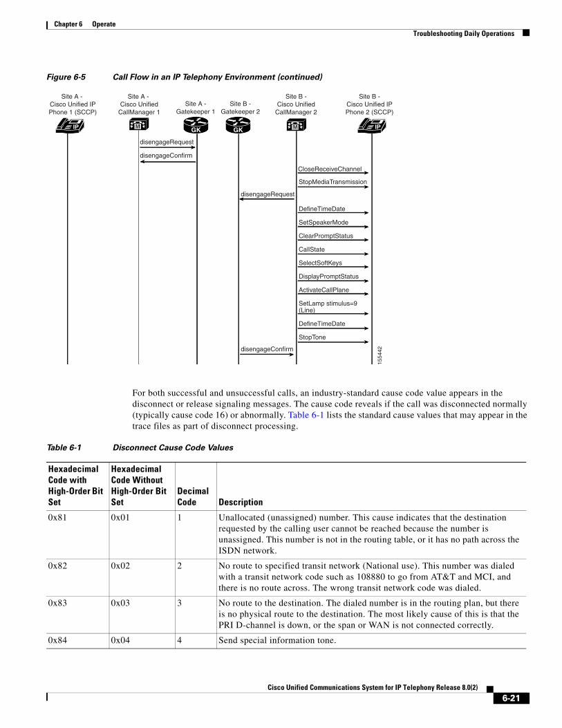
Chapter 6 Operate Troubleshooting Daily Operations
Figure 6-5 Call Flow in an IP Telephony Environment (continued)
For both successful and unsuccessful calls, an industry-standard cause code value appears in the disconnect or release signaling messages. The cause code reveals if the call was disconnected normally (typically cause code 16) or abnormally. Table 6-1 lists the standard cause values that may appear in the trace files as part of disconnect processing.
disengageRequest
disengageConfirm CloseReceiveChannel
IP IPM M
1554
42
StopMediaTransmission
DefineTimeDate
SetSpeakerMode
ClearPromptStatus
CallState
SelectSoftKeys
DisplayPromptStatus
ActivateCallPlane
SetLamp stimulus=9(Line)
DefineTimeDate
StopTone
disengageRequest
disengageConfirm
Site A - Cisco Unified IPPhone 1 (SCCP)
Site A - Cisco Unified
CallManager 1Site A -
Gatekeeper 1
GK GK
Site B -Gatekeeper 2
Site B -Cisco Unified
CallManager 2
Site B -Cisco Unified IPPhone 2 (SCCP)
Table 6-1 Disconnect Cause Code Values
Hexadecimal Code with High-Order Bit Set
Hexadecimal Code Without High-Order Bit Set
Decimal Code Description
0x81 0x01 1 Unallocated (unassigned) number. This cause indicates that the destination requested by the calling user cannot be reached because the number is unassigned. This number is not in the routing table, or it has no path across the ISDN network.
0x82 0x02 2 No route to specified transit network (National use). This number was dialed with a transit network code such as 108880 to go from AT&T and MCI, and there is no route across. The wrong transit network code was dialed.
0x83 0x03 3 No route to the destination. The dialed number is in the routing plan, but there is no physical route to the destination. The most likely cause of this is that the PRI D-channel is down, or the span or WAN is not connected correctly.
0x84 0x04 4 Send special information tone.
6-21Cisco Unified Communications System for IP Telephony Release 8.0(2)

Chapter 6 Operate Troubleshooting Daily Operations
0x85 0x05 5 Misdialed trunk prefix (National use).
0x86 0x06 6 Channel unacceptable.
0x87 0x07 7 Call awarded and being delivered in an established channel.
0x88 0x08 8 Preemption.
0x89 0x09 9 Preemption. Circuit reserved for reuse.
0x90 0x10 16 Normal call clearing. This is one of the most common codes and is received for many reasons. It usually occurs because someone hung up the call.
0x91 0x11 17 User busy. The number dialed is busy and cannot receive any more calls.
0x92 0x12 18 No user responding. The number that is being dialed has an active D-channel, but the far end chooses not to answer.
0x93 0x13 19 No answer from the user (user alerted). The number that is being dialed has an active D-channel, but the far end chooses not to answer.
0x94 0x14 20 Subscriber absent.
0x95 0x15 21 Call rejected.
0x96 0x16 22 Number changed. This cause code is generated when a subscriber on the PSTN has changed his or her phone number. Usually this message is accompanied by a progress indicator stating that in-band information is available. The PSTN provides an announcement in-band indicating the new phone number, if available.
0x9A 0x1A 26 Nonselected user clearing.
0x9B 0x1B 27 Destination is out of order. The number dialed is a working number, but the span is not active.
0x9C 0x1C 28 Invalid number format (address incomplete). This can happen when you are calling out using a network type number (enterprise) when you should be calling out Unknown or National.
0x9D 0x1D 29 Facility rejected.
0x9E 0x1E 30 Response to STATUS ENQUIRY.
0x9F 0x1F 31 Normal, unspecified. This is another common code. It happens when the network cannot determine what to do with the call being made.
0xA2 0x22 34 No circuit/channel is available. No B-channels are available to make the selected call.
0xA6 0x26 38 Network is out of order.
0xA7 0x27 39 Permanent frame mode connection is out of service.
0xA8 0x28 40 Permanent frame mode connection is operational.
0xA9 0x29 41 Temporary failure. The call was disconnected due to a network failure. This code appears for some long distance providers if the hunt sequence is incorrect. PRI lines must be set up for a flex hunt sequence (not a float hunt sequence).
0xAA 0x2A 42 Switching equipment congestion.
Table 6-1 Disconnect Cause Code Values (continued)
Hexadecimal Code with High-Order Bit Set
Hexadecimal Code Without High-Order Bit Set
Decimal Code Description
6-22Cisco Unified Communications System for IP Telephony Release 8.0(2)

Chapter 6 Operate Troubleshooting Daily Operations
0xAB 0x2B 43 Access information discarded. Usually reported when the far-end ISDN switch removes some piece of information before tandem-switching a call. For example, some PBXs strip the display IE before sending a call out toward the PSTN and send back a message with this cause code.
0xAC 0x2C 44 Requested circuit/channel is unavailable. This happens when you get in a glare condition: Both sides are selected top-down or bottom-up. Change the Allocation Direction (so that one end is top-down and the other is bottom-up).
0xAE 0x2E 46 Precedence call blocked.
0xAF 0x2F 47 Resource unavailable, unspecified. Whenever you see Cisco Unified Communications Manager initiate a disconnect with cause code 0xAF, 99% of the time the problem is related to a media setup failure. Check for codec capabilities mismatches, especially your regions configuration.
0xB1 0x31 49 Quality of service unavailable.
0xB2 0x32 50 Requested facility not subscribed. This code typically indicates you are trying to use a service you are not permitted to use. For example, you might be trying to make a voice call on an ISDN circuit provisioned for data only.
0xB5 0x35 53 Outgoing calls barred within Closed User Group (CUG).
0xB7 0x37 55 Incoming calls barred within CUG.
0xB9 0x39 57 Bearer capability not authorized. This code indicates that you are placing a call with a bearer capability you are not allowed to use.
0xBA 0x3A 58 Bearer capability not presently available. This code indicates that you are placing a call with a bearer capability for which the service provider does not currently have capacity to supply.
0xBE 0x3E 62 Inconsistency in designated outgoing access information and subscriber class.
0xBF 0x3F 63 Service or option unavailable, unspecified.
0xC1 0x41 65 Bearer capability not implemented. The cause could be one of the following occurrences:
• You need to change the PCM Type value to the setting appropriate for your country. This is the most common cause, especially in countries where G.711 A-law companding is the standard. If your gateway is configured for µ-law and the service provider or PBX is expecting A-law, you will see calls disconnected with this cause code.
• The central office (CO) does not understand an information element in the setup message.
• You are connected to a PBX and you are sending out a network type number when the switch accepts only Unknown or National.
• You are selecting European PRI and you have the progress indicators turned on when they should be off.
0xC2 0x42 66 Channel type not implemented.
0xC5 0x45 69 Requested facility not implemented.
Table 6-1 Disconnect Cause Code Values (continued)
Hexadecimal Code with High-Order Bit Set
Hexadecimal Code Without High-Order Bit Set
Decimal Code Description
6-23Cisco Unified Communications System for IP Telephony Release 8.0(2)

Chapter 6 Operate Troubleshooting Daily Operations
0xC6 0x46 70 Only restricted digital information bearer capability is available (National use).
0xCF 0x47 79 Service or option not implemented, unspecified.
0xD1 0x51 81 Invalid call reference value. This code indicates that the far-end switch did not recognize the call reference for a message sent by the gateway.
0xD2 0x52 82 Identified channel does not exist. This code indicates a call attempt on a channel that is not configured on the far end. This could happen if you are using a fractional PRI. As of Cisco Unified Communications Manager Release 3.3, fractional PRIs are no longer supported.
0xD3 0x53 83 A suspended call exists, but this call identity does not.
0xD4 0x54 84 Call identity in use.
0xD5 0x55 85 No call suspended.
0xD6 0x56 86 Call having the requested call identity has been cleared.
0xD7 0x57 87 User is not a member of CUG.
0xD8 0x58 88 Incompatible destination. The cause could be one of the following occurrences:
• The number being dialed is not capable of the type of call.
• You are calling a restricted line in unrestricted mode.
• You are calling a POTS phone using unrestricted mode.
0xDA 0x5A 90 Nonexistent CUG.
0xDB 0x5B 91 Invalid transit network selection (National use).
0xDF 0x5F 95 Invalid message, unspecified.
0xE0 0x60 96 Mandatory information element is missing. The far-end switch states that a message was received missing an information element it considers to be mandatory per the Q.931 specification.
0xE1 0x61 97 Message type nonexistent or not implemented.
0xE2 0x62 98 Message is incompatible with the call state, or the message type is nonexistent or not implemented. This code is usually indicative of an ISDN protocol mismatch. Each ISDN protocol variant has a slightly different state machine based on the state machines defined in the Q.931 specification. If the two sides of an ISDN connection are not configured for the same protocol, one side might violate the other's call state machine. If an ISDN message is sent that is not expected in the current call state, this cause is generated.
0xE3 0x63 99 An information element or parameter does not exist or is not implemented.
Table 6-1 Disconnect Cause Code Values (continued)
Hexadecimal Code with High-Order Bit Set
Hexadecimal Code Without High-Order Bit Set
Decimal Code Description
6-24Cisco Unified Communications System for IP Telephony Release 8.0(2)
Chapter 6 Operate Troubleshooting Daily Operations
Failover and Recovery ProceduresThe Disaster Recovery System (DRS), which can be invoked from Cisco Unified Communications Manager Administration, provides full data backup and restore capabilities for all servers in a Cisco Unified Communications Manager cluster. The Disaster Recovery System allows you to perform regularly scheduled automatic or user-invoked data backups. DRS supports only one backup schedule at a time.
The Cisco Disaster Recovery System performs a cluster-level backup, which means that it collects backups for all servers in a Cisco Unified Communications Manager cluster to a central location and archives the backup data to physical storage device.
When performing a system data restoration, you can choose which nodes in the cluster you want to restore.
The Disaster Recovery System includes the following capabilities:
• A user interface for performing backup and restore tasks.
• A distributed system architecture for performing backup and restore functions.
0xE4 0x64 100 Invalid information element contents. The cause could be one of the following occurrences:
• The call has an information element that is not understood by the switch being called. The E4 is usually followed by the information element that is causing the problem.
• The most common problem is that you are trying to place a call using a network number when the switch being called accepts only National, International, or Unknown dialing.
• This code is also generated when you are using Network-Specific Facilities as an element when they are not needed.
0xE5 0x65 101 The message is incompatible with the call state. This code is usually indicative of an ISDN protocol mismatch. Each ISDN protocol variant has a slightly different state machine based on the state machines defined in the Q.931 specification. If the two sides of an ISDN connection are not configured for the same protocol, one side might violate the other's call state machine. If an ISDN message is sent that is not expected in the current call state, this cause is generated.
0xE6 0x66 102 Recovery on timer expiry. This occurs when ISDN messages don't arrive in specified time according to the Q.931 specification. The E6 is sometimes followed by the timer that has expired (for example, 03 01 00—the 310 timer).
0xE7 0x67 103 Parameter nonexistent or not implemented—passed on (National use).
0xEE 0x6E 110 Message with unrecognized parameter discarded.
0xEF 0x6F 111 Protocol error, unspecified.
0xFF 0x7F 127 Interworking, unspecified.
Table 6-1 Disconnect Cause Code Values (continued)
Hexadecimal Code with High-Order Bit Set
Hexadecimal Code Without High-Order Bit Set
Decimal Code Description
6-25Cisco Unified Communications System for IP Telephony Release 8.0(2)

Chapter 6 Operate Additional Sites and Services
• A scheduling engine to initiate tasks at user-specified times.
• Archive backups to a physical tape drive or remote sftp server.
The Disaster Recovery System contains two key functions, Master Agent (MA) and Local Agent (LA). The Master Agent coordinates backup and restore activity with all the Local Agents. The system automatically activates both the Master Agent and the Local Agent on all nodes in the cluster. However, you can only access the Master Agent functions on the first node of the cluster.
For more information on the Cisco Unified Communications Manager Disaster Recovery System, see the Disaster Recovery System Administration Guide for Unified Communications Manager.
Additional Sites and ServicesSteps to Success is a Cisco methodology that outlines the tasks required to complete a successful customer engagement. Registered users can visit the Steps to Success resource site for Cisco Unified Communications process flows.
Cisco Unified Communications Services is a Cisco service offering that provides engineering expertise and best practices.
• Registered users can visit the Cisco Unified Communications Services partner site.
• Nonregistered users can visit the Cisco Unified Communications Services site.
6-26Cisco Unified Communications System for IP Telephony Release 8.0(2)
Cisco Unified Com
C H A P T E R 7
OptimizeOptimizing Your SystemOptimization covers any changes to an existing system, including hardware and software upgrades, that enhance the functionality and performance of your network.
Collecting and analyzing data from your system’s performance reports will provide crucial information for optimizing your system. By maintaining the routine system management procedures that you set up for your operations lifecycle, you will know when your traffic load increases, and when to increase your capacity.
Input to This Process
Your network has been operational for some period of time and is ready to optimize based on system performance criteria. Your daily operations and growing business needs provide continuous feedback for optimization.
Output of This Process
User feedback, audits, and test results provide data to continue optimizing the system.
Major Tasks in This Process
• Performing a System Upgrade
Performing a System UpgradeSee Plan and Prepare for Your System Upgrade on the Plan tab to plan your overall strategy.
Upgrade IP Telephony Components
Once you have your upgrade plan and preparations in place, conduct your system upgrade following the guidelines and sequence in Performing Your System Upgrade:
• See IP Telephony Deployment Models for the general upgrade sequence for the various components in the different deployment models, including Enterprise Single Site, Enterprise Multisite Centralized and SRST, and Enterprise Multisite WAN Distributed.
• See Upgrading IP Telephony Components for system-level upgrade procedures for each major upgrade strategy: single-stage system upgrade, multistaged system upgrade, and multistaged migration upgrade.
7-1munications System for IP Telephony Release 8.0(2)

Chapter 7 Optimize Additional Sites and Services
For related documentation on compatibility and component upgrades, see these topics:
• Compatibility Guides
• Component Release Notes and Installation and Upgrade Documentation
Additional Sites and ServicesSteps to Success is a Cisco methodology that outlines the tasks required to complete a successful customer engagement. Registered users can visit the Steps to Success resource site for Cisco Unified Communications process flows.
Cisco Unified Communications Services is a Cisco service offering that provides engineering expertise and best practices.
• Registered users can visit the Cisco Unified Communications Services partner site.
• Nonregistered users can visit the Cisco Unified Communications Services site.
7-2Cisco Unified Communications System for IP Telephony Release 8.0(2)

Cisco Unified Com
C H A P T E R 8
Resource LibraryUsing the Resource LibraryOn this tab you find an assortment of resources to help you learn more about Cisco Unified Communications.
• System Release Documentation
• Solution Reference Network Design
• Tested Deployment and Site Models
• Network Topology Diagrams
• Component Resources
• Unified Communications Demos
• System Compatibility Tool
• Ordering Guides
• End-of-Sale and End-of-Life Products
• Cisco Unified Workspace Licensing
• Documentation Wiki
System Release DocumentationThe following system-level documents are produced for Unified Communications System releases:
• System Description
• System Release Notes
• System Installation and Upgrade Manual
• System Test Results
8-1munications System for IP Telephony Release 8.0(2)

Chapter 8 Resource Library System Release Documentation
System DescriptionThis document provides an overview of the Cisco Unified Communications System Release 8.0(2). It describes the Cisco Unified Communications system-level approach, lists key features of the Cisco Unified Communications components, and illustrates the various Cisco Unified Communications deployment models.
• System Description for Cisco Unified Communications System, Release 8.0(2)
System Release NotesThese documents described the tested functionality, new and changed features, and limitations and restrictions for each of the following Cisco Unified Communications System Release 8.0(2) solutions:
• Contact Center
– System Release Notes for IP Telephony for Contact Center: Cisco Unified Communications System, Release 8.0(2)
• IP Telephony
– System Release Notes for IP Telephony: Cisco Unified Communications System, Release 8.0(2)
System Installation and Upgrade ManualThese documents provide installation and upgrade information about the components and configurations that were tested and verified as a part of Cisco Unified Communications System Release 8.0(2) testing for each of the following solutions:
• Contact Center
– System Installation and Upgrade Manual for IP Telephony for Contact Center: Cisco Unified Communications System, Release 8.0(2)
• IP Telephony
– System Installation and Upgrade Manual for IP Telephony: Cisco Unified Communications System, Release 8.0(2)
System Test ResultsThese documents described the system-level test cases executed on each of the following Cisco Unified Communications System Release 8.0(2) solutions:
• Contact Center
– System Test Results for Contact Center: Cisco Unified Communications System, Release 8.0(2)
• IP Telephony
– System Test Results for IP Telephony: Cisco Unified Communications System, Release 8.0(2)
8-2Cisco Unified Communications System for IP Telephony Release 8.0(2)

Chapter 8 Resource Library System Release Documentation
Test Results Information
Testing Objectives give information on the intent of system testing
The test results contain the following information:
• ID—Identifier for the test.
• Features Tested—Component feature tested.
• Case Title—Title of the test.
• Description—Description of the purpose of the test.
• Call Component Flow—Indicates the sequence of components involved in the test.
• Status—Result of the test and any defects related to the test case. Possible values are:
– Passed—Test case passed as described in the table.
– Failed—Test case failed and the reason is described in the listed defect.
– Passed with exception—Test case as described passed but an anomaly occurred that was not directly related to the functionality being tested. Possible anomalies are as follows:
The test steps were modified based on the actual feature implementation.
The test setup was modified based on the actual feature implementation.
The test results did not exactly match what was expected although the feature performed as required.
• Defects—Identifier for any defect that was opened against the test. If you have an account with Cisco.com, you can use the Bug Toolkit to view information about defects.
To access the Bug Toolkit, go to this URL:
– http://tools.cisco.com/Support/BugToolKit/
Testing Objectives
Cisco Systems validates Cisco Unified Communications systems by designing, installing, configuring, and testing hardware and software to achieve a predictable, effective, and reliable system. The intent of system testing is to validate the seamless interoperability and stability of the components that make up a complete and optimized Cisco Unified Communications system.
Testing performed for Cisco Unified Communications includes (but is not limited to) the following:
• Installation, Upgrade, and Usability Testing—To verify software installation and upgrades at the system level and usability for system components
• End-to-End Functionality Testing—To verify the end-to-end functionality of system components
• Basic Functionality and Feature Testing—To verify basic call flows and component features
• Customer Assurance Program (CAP) Scenario Testing—To re-create and test CAP scenarios based on TAC input
• Interoperability Testing—To verify the interoperability among system components
• Scalability Testing—To verify system functionality during scalability tests
• Performance, Load, and Stress Testing—To verify system functionality during performance, load, and stress tests
• Failover, Recovery, and Redundancy Testing—To verify system behavior during failover and recovery, and behavior in redundant configurations
8-3Cisco Unified Communications System for IP Telephony Release 8.0(2)

Chapter 8 Resource Library Solution Reference Network Design
Solution Reference Network DesignSolution Reference Network Design (SRND) guides provide considerations and guidelines for deploying components for the Cisco Unified Communications System. SRND resources are available at http://www.cisco.com/go/srnd.
Tested Deployment and Site ModelsCisco Unified Communications Systems Release 8.0(2) testing was designed to test the hardware and software components that work together in a multisite distributed deployment. For this testing, several site models were created. Each site model was designed to test a specific set of features and interactions. For information about the components, configurations, and environment tested in this Cisco Unified Communications Release, see Table 8-1.
Table 8-1 Tested Deployment and Site Models
Deployment Model Description
Single-Site Model This model is designed for autonomous offices in which most or all employees are IPC users. This model can support up to 30,000 users.
Multisite Centralized Call Processing Model This model is designed for distributed operations with a large central or headquarters site and multiple remote or branch sites. This model can support up to a total of 30,000 phones distributed among up to a maximum of 1000 sites. Based upon the bandwidth available, each site can support any number of users up to the overall total of 30,000 phones.
Multisite Distributed Call Processing Model This model is designed for organizations with large user populations or large numbers of geographically distributed sites resulting in the need for more than a single call processing entity. This model is suited for deployments that require multiple Cisco Unified Communications Manager clusters or Cisco Unified Communications Manager Express platforms. Each call processing entity in this model is configured as a Single-Site Model or Multisite Centralized Call Processing Model and each has a common dial plan and feature set.
Clustering Over WAN Call Processing Model This model is designed for organizations with large user populations across multiple sites that are connected by an IP WAN with the QoS features enabled. It supports the Local Failover Deployment Model and the Remote Failover Deployment Model.
8-4Cisco Unified Communications System for IP Telephony Release 8.0(2)
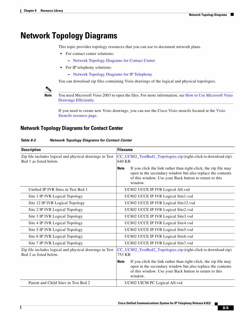
Chapter 8 Resource Library Network Topology Diagrams
Network Topology DiagramsThis topic provides topology resources that you can use to document network plans.
• For contact center solutions:
– Network Topology Diagrams for Contact Center
• For IP telephony solutions:
– Network Topology Diagrams for IP Telephony
You can download zip files containing Visio drawings of the logical and physical topologies.
Note You need Microsoft Visio 2003 to open the files. For more information, see How to Use Microsoft Visio Drawings Efficiently.
If you need to create new Visio drawings, you can use the Cisco Visio stencils located at the Visio Stencils resource page.
Network Topology Diagrams for Contact Center
Table 8-2 Network Topology Diagrams for Contact Center
Description Filename
Zip file includes logical and physical drawings in Test Bed 1 as listed below.
CC_UC802_TestBed1_Topologies.zip (right-click to download zip) 640 KB
Note If you click the link rather than right-click, the zip file may open in the secondary window but also replace the contents of this window. Use your Back button to return to this window.
Unified IP IVR Sites in Test Bed 1 UC802 UCCE IP IVR Logical All.vsd
Site 1 IP IVR Logical Topology UC802 UCCE IP IVR Logical Site1.vsd
Site 12 IP IVR Logical Topology UC802 UCCE IP IVR Logical Site12.vsd
Site 2 IP IVR Logical Topology UC802 UCCE IP IVR Logical Site2.vsd
Site 3 IP IVR Logical Topology UC802 UCCE IP IVR Logical Site3.vsd
Site 4 IP IVR Logical Topology UC802 UCCE IP IVR Logical Site4.vsd
Site 5 IP IVR Logical Topology UC802 UCCE IP IVR Logical Site5.vsd
Site 6 IP IVR Logical Topology UC802 UCCE IP IVR Logical Site6.vsd
Site 7 IP IVR Logical Topology UC802 UCCE IP IVR Logical Site7.vsd
Zip file includes logical and physical drawings in Test Bed 2 as listed below.
CC_UC802_TestBed2_Topologies.zip (right-click to download zip) 753 KB
Note If you click the link rather than right-click, the zip file may open in the secondary window but also replace the contents of this window. Use your Back button to return to this window.
Parent and Child Sites in Test Bed 2 UC802 UICM PC Logical All.vsd
8-5Cisco Unified Communications System for IP Telephony Release 8.0(2)

Chapter 8 Resource Library Network Topology Diagrams
Network Topology Diagrams for IP Telephony
Site 1 Parent and Child Logical Topology UC802 UICM PC Logical Site1.vsd
Site 4 Parent and Child Logical Topology UC802 UICM PC Logical Site4.vsd
Site 5 Parent and Child Logical Topology UC802 UICM PC Logical Site5.vsd
Site 8 Parent and Child Logical Topology UC802 UICM PC Logical Site8.vsd
Site 9 Parent and Child Logical Topology UC802 UICM PC Logical Site9.vsd
Zip file includes logical and physical drawings in Test Bed 3 as listed below.
CC_UC802_TestBed3_Topologies.zip (right-click to download zip) 1.7 MB
Note If you click the link rather than right-click, the zip file may open in the secondary window but also replace the contents of this window. Use your Back button to return to this window.
Unified CVP Sites in Test Bed 3 UC802 UCCE CVP Logical All.vsd
Site 1 CVP Logical Topology UC802 UCCE CVP Logical Site1.vsd
UCS Hardware Logical Topology UC802 UCCE CVP Logical Site 1UCS.vsd
Site 2 CVP Logical Topology UC802 UCCE CVP Logical Site2.vsd
Site 3 CVP Logical Topology UC802 UCCE CVP Logical Site3.vsd
Site 5 CVP Logical Topology UC802 UCCE CVP Logical Site5.vsd
Site 6 CVP Logical Topology UC802 UCCE CVP Logical Site6.vsd
Site 7 CVP Logical Topology UC802 UCCE CVP Logical Site7.vsd
Site 8 CVP Logical Topology UC802 UCCE CVP Logical Site8.vsd
Table 8-3 Network Topology Diagrams for IP Telephony
Description Filename
Zip file includes the site model topology drawings listed below.
IPT_UC802_Site_Models.zip (5.1) MB
Note If you click the link rather than right-click, the zip file may open in the secondary window but also replace the contents of this window. Use your Back button to return to this window.
All test sites in North America Multisite Distributed deployment
SiteModel_NorthAmerica_All.vsd
Very Large Campus Clustering over the WAN (SJC-RFD) site model
SiteModel_LargeCampus_SJCRFD.vsd
Large SIP Site (DFW) site model SiteModel_LargeSIP_DFW.vsd
Unified Communications Manager Business Edition Sites with Unified SRST (AZO and ACY) site model
SiteModel_MediumBusiness_AZOACY.vsd
Table 8-2 Network Topology Diagrams for Contact Center (continued)
Description Filename
8-6Cisco Unified Communications System for IP Telephony Release 8.0(2)
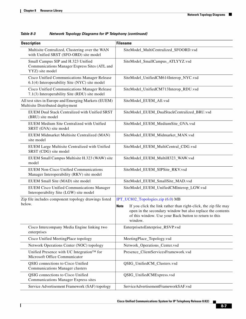
Chapter 8 Resource Library Network Topology Diagrams
Multisite Centralized, Clustering over the WAN with Unified SRST (SFO-ORD) site model
SiteModel_MultiCentralized_SFOORD.vsd
Small Campus SIP and H.323 Unified Communications Manager Express Sites (ATL and YYZ) site model
SiteModel_SmallCampus_ATLYYZ.vsd
Cisco Unified Communications Manager Release 6.1(4) Interoperability Site (NYC) site model
SiteModel_UnifiedCM614Interop_NYC.vsd
Cisco Unified Communications Manager Release 7.1(3) Interoperability Site (RDU) site model
SiteModel_UnifiedCM713Interop_RDU.vsd
All test sites in Europe and Emerging Markets (EUEM) Multisite Distributed deployment
SiteModel_EUEM_All.vsd
EUEM Dual Stack Centralized with Unified SRST (BRU) site model
SiteModel_EUEM_DualStackCentralized_BRU.vsd
EUEM Medium Site Centralized with Unified SRST (GVA) site model
SiteModel_EUEM_MediumSite_GVA.vsd
EUEM Midmarket Multisite Centralized (MAN) site model
SiteModel_EUEM_Midmarket_MAN.vsd
EUEM Large Multisite Centralized with Unified SRST (CDG) site model
SiteModel_EUEM_MultiCentral_CDG.vsd
EUEM Small Campus Multisite H.323 (WAW) site model
SiteModel_EUEM_MultiH323_WAW.vsd
EUEM Non-Cisco Unified Communications Manager Interoperability (RKV) site model
SiteModel_EUEM_SIPSite_RKV.vsd
EUEM Small Site (MAD) site model SiteModel_EUEM_SmallSite_MAD.vsd
EUEM Cisco Unified Communications Manager Interoperability Site (LGW) site model
SiteModel_EUEM_UnifiedCMInterop_LGW.vsd
Zip file includes component topology drawings listed below.
IPT_UC802_Topologies.zip (6.0) MB
Note If you click the link rather than right-click, the zip file may open in the secondary window but also replace the contents of this window. Use your Back button to return to this window.
Cisco Intercompany Media Engine linking two enterprises
EnterprisetoEnterprise_RSVP.vsd
Cisco Unified MeetingPlace topology MeetingPlace_Topology.vsd
Network Operations Center (NOC) topology Network_Operations_Center.vsd
Unified Presence with UC Integration™ for Microsoft Office Communicator
Presence_ClientServicesFramework.vsd
QSIG connections to Cisco Unified Communications Manager clusters
QSIG_UnifiedCM_Clusters.vsd
QSIG connections to Cisco Unified Communications Manager Express sites
QSIG_UnifiedCMExpress.vsd
Service Advertisement Framework (SAF) topology ServiceAdvertisementFrameworkSAF.vsd
Table 8-3 Network Topology Diagrams for IP Telephony (continued)
Description Filename
8-7Cisco Unified Communications System for IP Telephony Release 8.0(2)
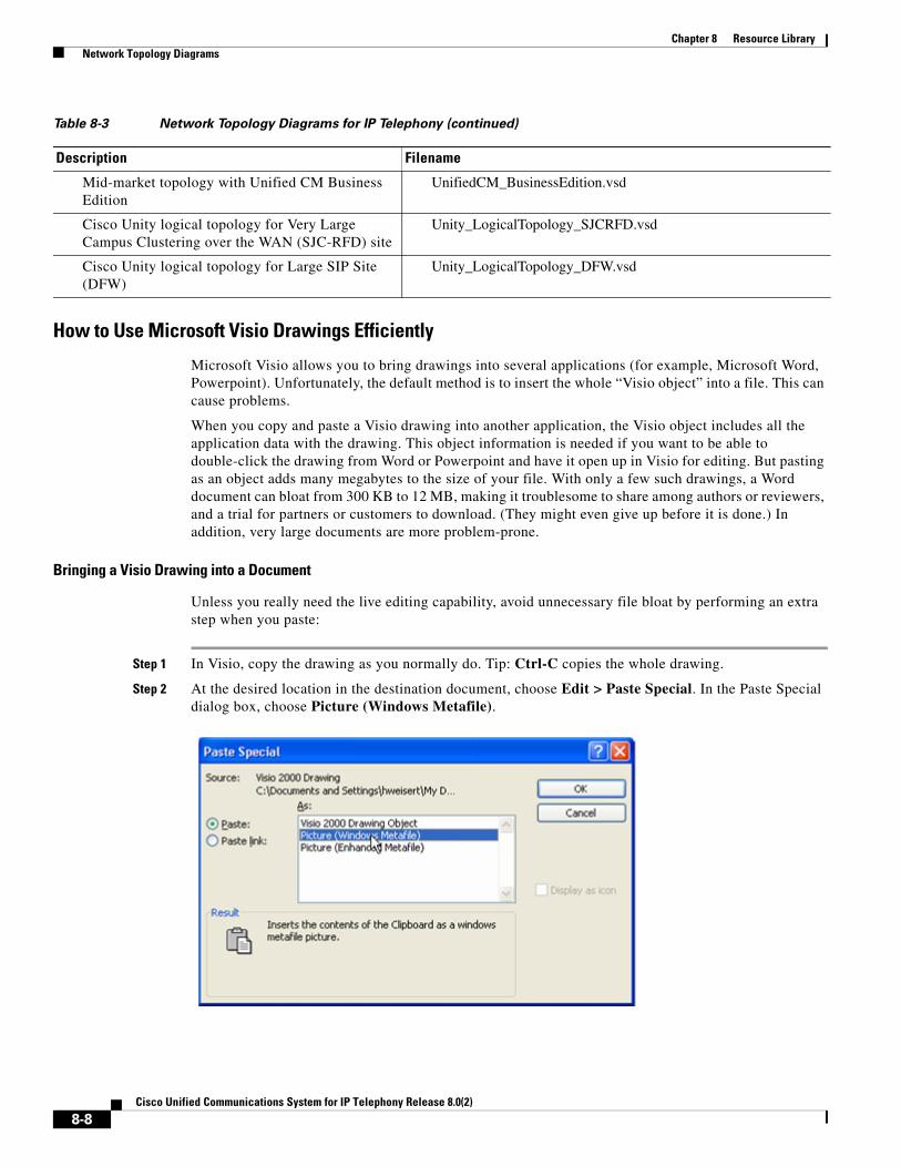
Chapter 8 Resource Library Network Topology Diagrams
How to Use Microsoft Visio Drawings Efficiently
Microsoft Visio allows you to bring drawings into several applications (for example, Microsoft Word, Powerpoint). Unfortunately, the default method is to insert the whole “Visio object” into a file. This can cause problems.
When you copy and paste a Visio drawing into another application, the Visio object includes all the application data with the drawing. This object information is needed if you want to be able to double-click the drawing from Word or Powerpoint and have it open up in Visio for editing. But pasting as an object adds many megabytes to the size of your file. With only a few such drawings, a Word document can bloat from 300 KB to 12 MB, making it troublesome to share among authors or reviewers, and a trial for partners or customers to download. (They might even give up before it is done.) In addition, very large documents are more problem-prone.
Bringing a Visio Drawing into a Document
Unless you really need the live editing capability, avoid unnecessary file bloat by performing an extra step when you paste:
Step 1 In Visio, copy the drawing as you normally do. Tip: Ctrl-C copies the whole drawing.
Step 2 At the desired location in the destination document, choose Edit > Paste Special. In the Paste Special dialog box, choose Picture (Windows Metafile).
Mid-market topology with Unified CM Business Edition
UnifiedCM_BusinessEdition.vsd
Cisco Unity logical topology for Very Large Campus Clustering over the WAN (SJC-RFD) site
Unity_LogicalTopology_SJCRFD.vsd
Cisco Unity logical topology for Large SIP Site (DFW)
Unity_LogicalTopology_DFW.vsd
Table 8-3 Network Topology Diagrams for IP Telephony (continued)
Description Filename
8-8Cisco Unified Communications System for IP Telephony Release 8.0(2)

Chapter 8 Resource Library Component Resources
Step 3 Click OK. The drawing pastes as an ordinary picture. If it is not positioned properly, choose Format > Picture, click the Layout tab and select In line with text. This is generally the most reliable layout option.
The Bottom Line
Do not use the paste default (Edit > Paste or Ctrl-V) to paste Visio drawings. Always use Paste Special.
Downsizing Existing Drawings
If a document is larger than it should be, you can check to see if the Visio drawings are the reason and, if so, fix the problem.
Step 1 With the drawing selected in the Word or Powerpoint document, choose Edit. At the bottom of the Edit menu, you will see one of the following:
• Edit Object, if the drawing was inserted by simple pasting. It is a Visio object and taking up much more file space than it needs to. Go on to step 2.
• Edit Picture, if the drawing was inserted properly, as a picture. It is not the source of the large file size.
Step 2 If the drawing is an object, cut it (Ctrl-X), then repaste it as in Bringing a Visio Drawing into a Document.
Tip You can easily click through the document to check each picture by using Word's handy Go To feature: Where you want to start searching, press Ctrl-G. In the Go to what list, select Graphic and click Next. You go to the next graphic. Click it to select, and then check as in step 1. If needed, repaste as in step 2. Click Next and continue these steps for other graphics.
Component ResourcesFor Cisco Unified Communications Release 8.0(2), there are two types of resources that provide descriptive information on each component in the solution:
• Component Resources Documentation
• Configuration Command Files
Component Resources DocumentationDepending on your Unified Communications solution type, choose one of the following sets of component resources documentation:
• Component Resources Documentation for Contact Center
• Component Resources Documentation for IP Telephony
8-9Cisco Unified Communications System for IP Telephony Release 8.0(2)
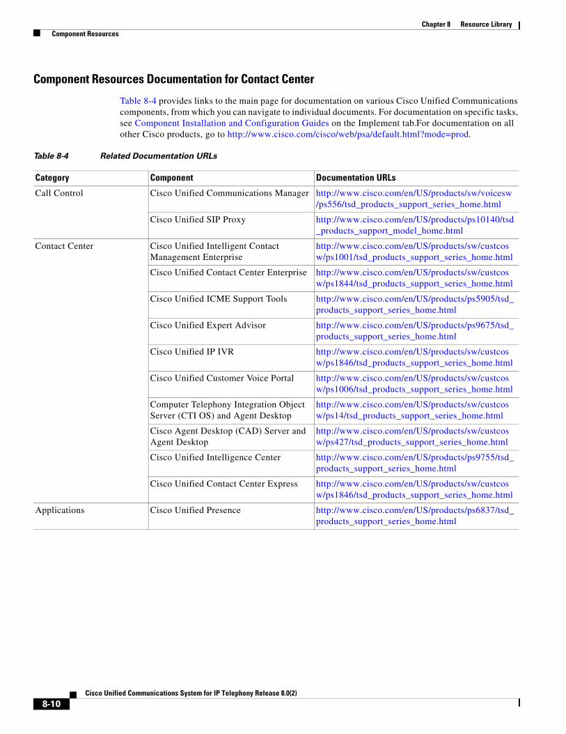
Chapter 8 Resource Library Component Resources
Component Resources Documentation for Contact Center
Table 8-4 provides links to the main page for documentation on various Cisco Unified Communications components, from which you can navigate to individual documents. For documentation on specific tasks, see Component Installation and Configuration Guides on the Implement tab.For documentation on all other Cisco products, go to http://www.cisco.com/cisco/web/psa/default.html?mode=prod.
Table 8-4 Related Documentation URLs
Category Component Documentation URLs
Call Control Cisco Unified Communications Manager http://www.cisco.com/en/US/products/sw/voicesw/ps556/tsd_products_support_series_home.html
Cisco Unified SIP Proxy http://www.cisco.com/en/US/products/ps10140/tsd_products_support_model_home.html
Contact Center Cisco Unified Intelligent Contact Management Enterprise
http://www.cisco.com/en/US/products/sw/custcosw/ps1001/tsd_products_support_series_home.html
Cisco Unified Contact Center Enterprise http://www.cisco.com/en/US/products/sw/custcosw/ps1844/tsd_products_support_series_home.html
Cisco Unified ICME Support Tools http://www.cisco.com/en/US/products/ps5905/tsd_products_support_series_home.html
Cisco Unified Expert Advisor http://www.cisco.com/en/US/products/ps9675/tsd_products_support_series_home.html
Cisco Unified IP IVR http://www.cisco.com/en/US/products/sw/custcosw/ps1846/tsd_products_support_series_home.html
Cisco Unified Customer Voice Portal http://www.cisco.com/en/US/products/sw/custcosw/ps1006/tsd_products_support_series_home.html
Computer Telephony Integration Object Server (CTI OS) and Agent Desktop
http://www.cisco.com/en/US/products/sw/custcosw/ps14/tsd_products_support_series_home.html
Cisco Agent Desktop (CAD) Server and Agent Desktop
http://www.cisco.com/en/US/products/sw/custcosw/ps427/tsd_products_support_series_home.html
Cisco Unified Intelligence Center http://www.cisco.com/en/US/products/ps9755/tsd_products_support_series_home.html
Cisco Unified Contact Center Express http://www.cisco.com/en/US/products/sw/custcosw/ps1846/tsd_products_support_series_home.html
Applications Cisco Unified Presence http://www.cisco.com/en/US/products/ps6837/tsd_products_support_series_home.html
8-10Cisco Unified Communications System for IP Telephony Release 8.0(2)
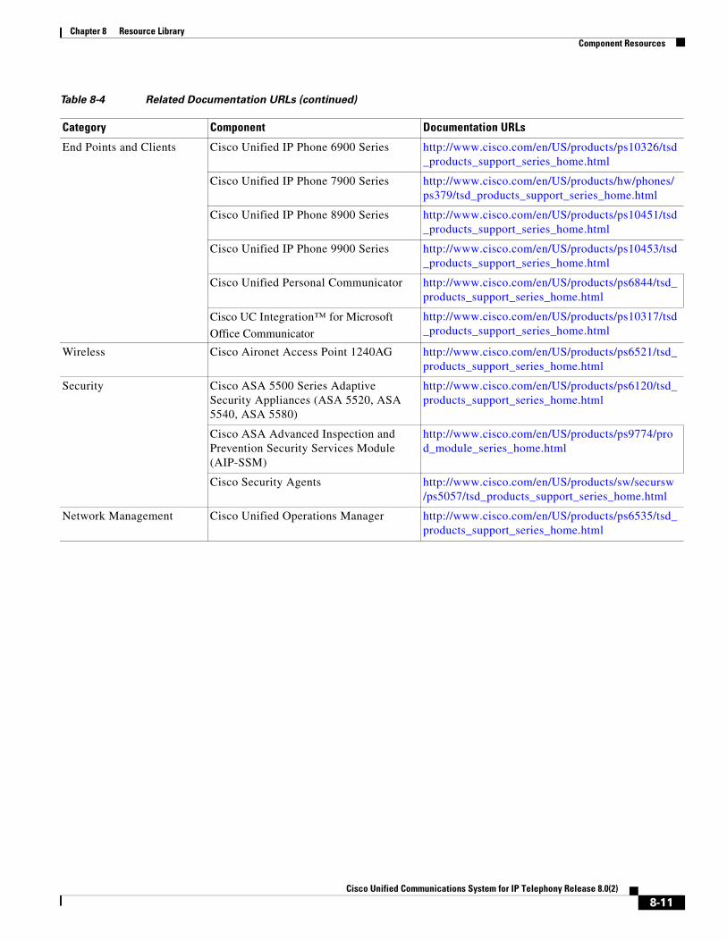
Chapter 8 Resource Library Component Resources
End Points and Clients Cisco Unified IP Phone 6900 Series http://www.cisco.com/en/US/products/ps10326/tsd_products_support_series_home.html
Cisco Unified IP Phone 7900 Series http://www.cisco.com/en/US/products/hw/phones/ps379/tsd_products_support_series_home.html
Cisco Unified IP Phone 8900 Series http://www.cisco.com/en/US/products/ps10451/tsd_products_support_series_home.html
Cisco Unified IP Phone 9900 Series http://www.cisco.com/en/US/products/ps10453/tsd_products_support_series_home.html
Cisco Unified Personal Communicator http://www.cisco.com/en/US/products/ps6844/tsd_products_support_series_home.html
Cisco UC Integration™ for Microsoft
Office Communicator
http://www.cisco.com/en/US/products/ps10317/tsd_products_support_series_home.html
Wireless Cisco Aironet Access Point 1240AG http://www.cisco.com/en/US/products/ps6521/tsd_products_support_series_home.html
Security Cisco ASA 5500 Series Adaptive Security Appliances (ASA 5520, ASA 5540, ASA 5580)
http://www.cisco.com/en/US/products/ps6120/tsd_products_support_series_home.html
Cisco ASA Advanced Inspection and Prevention Security Services Module (AIP-SSM)
http://www.cisco.com/en/US/products/ps9774/prod_module_series_home.html
Cisco Security Agents http://www.cisco.com/en/US/products/sw/secursw/ps5057/tsd_products_support_series_home.html
Network Management Cisco Unified Operations Manager http://www.cisco.com/en/US/products/ps6535/tsd_products_support_series_home.html
Table 8-4 Related Documentation URLs (continued)
Category Component Documentation URLs
8-11Cisco Unified Communications System for IP Telephony Release 8.0(2)
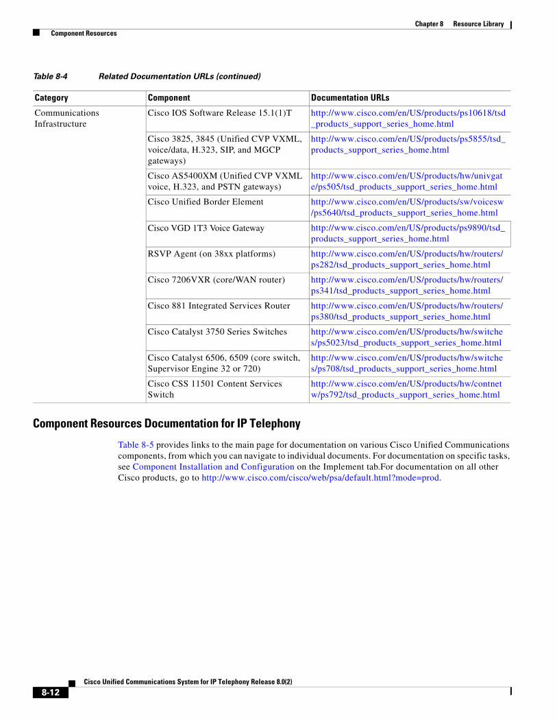
Chapter 8 Resource Library Component Resources
Component Resources Documentation for IP Telephony
Table 8-5 provides links to the main page for documentation on various Cisco Unified Communications components, from which you can navigate to individual documents. For documentation on specific tasks, see Component Installation and Configuration on the Implement tab.For documentation on all other Cisco products, go to http://www.cisco.com/cisco/web/psa/default.html?mode=prod.
Communications Infrastructure
Cisco IOS Software Release 15.1(1)T http://www.cisco.com/en/US/products/ps10618/tsd_products_support_series_home.html
Cisco 3825, 3845 (Unified CVP VXML, voice/data, H.323, SIP, and MGCP gateways)
http://www.cisco.com/en/US/products/ps5855/tsd_products_support_series_home.html
Cisco AS5400XM (Unified CVP VXML voice, H.323, and PSTN gateways)
http://www.cisco.com/en/US/products/hw/univgate/ps505/tsd_products_support_series_home.html
Cisco Unified Border Element http://www.cisco.com/en/US/products/sw/voicesw/ps5640/tsd_products_support_series_home.html
Cisco VGD 1T3 Voice Gateway http://www.cisco.com/en/US/products/ps9890/tsd_products_support_series_home.html
RSVP Agent (on 38xx platforms) http://www.cisco.com/en/US/products/hw/routers/ps282/tsd_products_support_series_home.html
Cisco 7206VXR (core/WAN router) http://www.cisco.com/en/US/products/hw/routers/ps341/tsd_products_support_series_home.html
Cisco 881 Integrated Services Router http://www.cisco.com/en/US/products/hw/routers/ps380/tsd_products_support_series_home.html
Cisco Catalyst 3750 Series Switches http://www.cisco.com/en/US/products/hw/switches/ps5023/tsd_products_support_series_home.html
Cisco Catalyst 6506, 6509 (core switch, Supervisor Engine 32 or 720)
http://www.cisco.com/en/US/products/hw/switches/ps708/tsd_products_support_series_home.html
Cisco CSS 11501 Content Services Switch
http://www.cisco.com/en/US/products/hw/contnetw/ps792/tsd_products_support_series_home.html
Table 8-4 Related Documentation URLs (continued)
Category Component Documentation URLs
8-12Cisco Unified Communications System for IP Telephony Release 8.0(2)
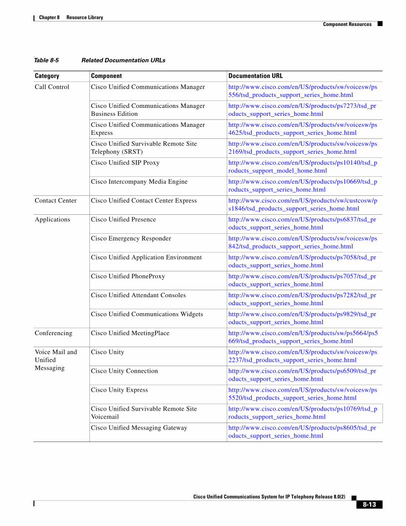
Chapter 8 Resource Library Component Resources
. Table 8-5 Related Documentation URLs
Category Component Documentation URL
Call Control Cisco Unified Communications Manager http://www.cisco.com/en/US/products/sw/voicesw/ps556/tsd_products_support_series_home.html
Cisco Unified Communications Manager Business Edition
http://www.cisco.com/en/US/products/ps7273/tsd_products_support_series_home.html
Cisco Unified Communications Manager Express
http://www.cisco.com/en/US/products/sw/voicesw/ps4625/tsd_products_support_series_home.html
Cisco Unified Survivable Remote Site Telephony (SRST)
http://www.cisco.com/en/US/products/sw/voicesw/ps2169/tsd_products_support_series_home.html
Cisco Unified SIP Proxy http://www.cisco.com/en/US/products/ps10140/tsd_products_support_model_home.html
Cisco Intercompany Media Engine http://www.cisco.com/en/US/products/ps10669/tsd_products_support_series_home.html
Contact Center Cisco Unified Contact Center Express http://www.cisco.com/en/US/products/sw/custcosw/ps1846/tsd_products_support_series_home.html
Applications Cisco Unified Presence http://www.cisco.com/en/US/products/ps6837/tsd_products_support_series_home.html
Cisco Emergency Responder http://www.cisco.com/en/US/products/sw/voicesw/ps842/tsd_products_support_series_home.html
Cisco Unified Application Environment http://www.cisco.com/en/US/products/ps7058/tsd_products_support_series_home.html
Cisco Unified PhoneProxy http://www.cisco.com/en/US/products/ps7057/tsd_products_support_series_home.html
Cisco Unified Attendant Consoles http://www.cisco.com/en/US/products/ps7282/tsd_products_support_series_home.html
Cisco Unified Communications Widgets http://www.cisco.com/en/US/products/ps9829/tsd_products_support_series_home.html
Conferencing Cisco Unified MeetingPlace http://www.cisco.com/en/US/products/sw/ps5664/ps5669/tsd_products_support_series_home.html
Voice Mail and Unified Messaging
Cisco Unity http://www.cisco.com/en/US/products/sw/voicesw/ps2237/tsd_products_support_series_home.html
Cisco Unity Connection http://www.cisco.com/en/US/products/ps6509/tsd_products_support_series_home.html
Cisco Unity Express http://www.cisco.com/en/US/products/sw/voicesw/ps5520/tsd_products_support_series_home.html
Cisco Unified Survivable Remote Site Voicemail
http://www.cisco.com/en/US/products/ps10769/tsd_products_support_series_home.html
Cisco Unified Messaging Gateway http://www.cisco.com/en/US/products/ps8605/tsd_products_support_series_home.html
8-13Cisco Unified Communications System for IP Telephony Release 8.0(2)

Chapter 8 Resource Library Component Resources
Endpoints and Clients
Cisco Unified SIP Phone 3900 Series http://www.cisco.com/en/US/products/ps7193/tsd_products_support_series_home.html
Cisco Unified IP Phone 6900 Series http://www.cisco.com/en/US/products/ps10326/tsd_products_support_series_home.html
Cisco Unified IP Phone 7900 Series http://www.cisco.com/en/US/products/hw/phones/ps379/tsd_products_support_series_home.html
Cisco Unified IP Phone 8900 Series http://www.cisco.com/en/US/products/ps10451/tsd_products_support_series_home.html
Cisco Unified IP Phone 9900 Series http://www.cisco.com/en/US/products/ps10453/tsd_products_support_series_home.html
Cisco IP Communicator http://www.cisco.com/en/US/products/sw/voicesw/ps5475/tsd_products_support_series_home.html
Cisco Unified Personal Communicator http://www.cisco.com/en/US/products/ps6844/tsd_products_support_series_home.html
Cisco UC Integration™ for Microsoft Office
Communicator
http://www.cisco.com/en/US/products/ps10317/tsd_products_support_series_home.html
Cisco UC Integration™ for WebEx Connect http://www.cisco.com/en/US/products/ps10627/tsd_products_support_series_home.html
Cisco Unified Video Advantage http://www.cisco.com/en/US/products/sw/voicesw/ps5662/tsd_products_support_series_home.html
Wireless and Mobility
Cisco Aironet 1200 Series Access Points http://www.cisco.com/en/US/products/hw/wireless/ps430/tsd_products_support_series_home.html
Cisco Unified Mobility Advantage http://www.cisco.com/en/US/products/ps7270/tsd_products_support_series_home.html
Cisco Unified Mobile Communicator http://www.cisco.com/en/US/products/ps7271/tsd_products_support_series_home.html
Security Cisco ASA 5500 Series Adaptive Security Appliances (ASA 5520, ASA 5540, ASA 5580)
http://www.cisco.com/en/US/products/ps6120/tsd_products_support_series_home.html
Cisco ASA Advanced Inspection and Prevention Security Services Module (AIP-SSM)
http://www.cisco.com/en/US/products/ps9774/prod_module_series_home.html
Cisco Security Agents http://www.cisco.com/en/US/products/sw/secursw/ps5057/tsd_products_support_series_home.html
Cisco Enterprise Policy Manager http://www.cisco.com/en/US/products/ps9529/tsd_products_support_series_home.html
Table 8-5 Related Documentation URLs (continued)
Category Component Documentation URL
8-14Cisco Unified Communications System for IP Telephony Release 8.0(2)

Chapter 8 Resource Library Component Resources
Network Management
Cisco Unified Operations Manager http://www.cisco.com/en/US/products/ps6535/tsd_products_support_series_home.html
Cisco Unified Service Monitor http://www.cisco.com/en/US/products/ps6536/tsd_products_support_series_home.html
Cisco Unified Service Statistics Manager http://www.cisco.com/en/US/products/ps7285/tsd_products_support_series_home.html
Cisco Unified Provisioning Manager http://www.cisco.com/en/US/products/ps7125/tsd_products_support_series_home.html
Cisco Unified Readiness Assessment Manager http://www.cisco.com/en/US/products/ps7134/tsd_products_support_series_home.html
Cisco Resource Management Essentials (RME) http://www.cisco.com/en/US/products/sw/cscowork/ps2073/tsd_products_support_series_home.html
Table 8-5 Related Documentation URLs (continued)
Category Component Documentation URL
8-15Cisco Unified Communications System for IP Telephony Release 8.0(2)

Chapter 8 Resource Library Component Resources
Communications Infrastructure
Cisco IOS Software Release 15.1(1)T http://www.cisco.com/en/US/products/ps10618/tsd_products_support_series_home.html
Cisco 870, 881 Integrated Services Routers http://www.cisco.com/en/US/products/hw/routers/ps380/tsd_products_support_series_home.html
Cisco 1861 Integrated Services Router http://www.cisco.com/en/US/products/ps5853/tsd_products_support_series_home.html
Cisco 2800 Series Integrated Services Routers http://www.cisco.com/en/US/products/ps5854/tsd_products_support_series_home.html
Cisco 2900 Series Integrated Services Routers http://www.cisco.com/en/US/products/ps10537/tsd_products_support_series_home.html
Cisco 3800 Series Integrated Services Routers http://www.cisco.com/en/US/products/ps5855/tsd_products_support_series_home.html
Cisco 3900 Integrated Services Routers http://www.cisco.com/en/US/products/ps10536/tsd_products_support_series_home.html
Cisco 7200 Series Voice Gateways http://www.cisco.com/en/US/products/hw/routers/ps341/tsd_products_support_series_home.html
Cisco Unified Border Element http://www.cisco.com/en/US/products/sw/voicesw/ps5640/tsd_products_support_series_home.html
Cisco VGD 1T3 Voice Gateway http://www.cisco.com/en/US/products/ps9890/tsd_products_support_series_home.html
Cisco VG30D Voice Gateway http://www.cisco.com/en/US/products/ps10601/tsd_products_support_series_home.html
Cisco Catalyst 3560 Series Access Switches http://www.cisco.com/en/US/products/hw/switches/ps5528/tsd_products_support_series_home.html
Cisco Catalyst 3750 Series Data Center Switches
http://www.cisco.com/en/US/products/hw/switches/ps5023/tsd_products_support_series_home.html
Cisco Catalyst 4500 Series Access Switches http://www.cisco.com/en/US/products/hw/switches/ps4324/tsd_products_support_series_home.html
Cisco Catalyst 6600 Series Voice Gateways http://www.cisco.com/en/US/products/hw/switches/ps700/tsd_products_support_eol_series_home.html
Cisco VG224/248 Analog Voice Gateways http://www.cisco.com/en/US/products/hw/gatecont/ps2250/tsd_products_support_series_home.html
Cisco ATA 186,188 (analog telephony adaptor) http://www.cisco.com/en/US/products/hw/gatecont/ps514/tsd_products_support_series_home.html
Table 8-5 Related Documentation URLs (continued)
Category Component Documentation URL
8-16Cisco Unified Communications System for IP Telephony Release 8.0(2)

Chapter 8 Resource Library Component Resources
Configuration Command FilesTo understand how various components were configured during Unified Communications system testing, review the contents of the ZIP archives described in one of the following sections:
• Configuration Command Files for Contact Center
• Configuration Command Files for IP Telephony
Additional system-level configuration examples are available on the Cisco DocWiki at http://docwiki.cisco.com/wiki/Category:Unified_Communications_System_Implementation
Configuration Command Files for Contact Center
Table 8-6 describes the contents of three ZIP files that you can download. Each ZIP file contains text files that contain the output from issuing a show running-config IOS command on various infrastructure components in the contact center test beds.
Table 8-6 Configuration Command Files for Contact Center
Description Filename
Test Bed 1 Call Flows: Cisco Unified Communications Manager Post-Routed Call Flow Components
CC_UC802_UnifiedCM_PostRoute_Configs.zip (right-click to download zip) includes the files below.
Note If you click the link rather than right-click, the zip file may open in the secondary window but also replace the contents of this window. Use your Back button to return to this window.
Site1 Cisco 3750 Switch cs1-3750-sw.txt
Site1 Cisco 3845 Gateway1 cs1-3845-gw1.txt
Site1 Cisco 3845 Gateway12 cs1-3845-gw12.txt
Site1 Cisco 3845 Gateway2 cs1-3845-gw2.txt
Site1 Cisco 3845 Conference/Transcoder Bridge cs1-3845-transcoder.txt
Site1 Cisco 6509 Switch cs1-6509-sw.txt
Site1 Cisco 7206VXR Router cs1-7206.txt
Site2 Cisco 3750 Switch cs2-3750-sw.txt
Site2 Cisco 3845 Conference/Transcoder Bridge cs2-3845-transcoder.txt
Site2 Cisco 7206VXR Router cs2-7206.txt
Site3 Cisco 3750 Switch cs3-3750-sw.txt
Site3 Cisco 3845 Conference/Transcoder Bridge cs3-3845-transcoder.txt
Site3 Cisco 7206VXR Router cs3-7206.txt
Site4 Cisco 3750 Switch cs4-3750-sw.txt
Site4 Cisco 3845 Gatekeeper cs4-3845-gk.txt
Site4 Cisco 3845 Conference/Transcoder Bridge cs4-3845-transcoder.txt
Site4 Cisco AS5400HPX Gateway1 cs4-5400-gw1.txt
Site4 Cisco AS5400HPX Gateway2 cs4-5400-gw2.txt
Site4 Cisco AS5400HPX Gateway3 cs4-5400-gw3.txt
8-17Cisco Unified Communications System for IP Telephony Release 8.0(2)

Chapter 8 Resource Library Component Resources
Site4 Cisco 6509 Switch cs4-6509-sw.txt
Site4 Cisco 7206VXR Router cs4-7206.txt
Site5 Cisco 3750 Switch1 cs5-3750-sw.txt
Site5 Cisco 3750 Switch2 cs5-3750-sw2.txt
Site5 Cisco 3825 Unified SIP Proxy1 cs5-3825-cusp1.txt
Site5 Cisco 3825 Unified SIP Proxy2 cs5-3825-cusp2.txt
Site5 Cisco 3845 Egress Gateway1 cs5-3845-egressgw1.txt
Site5 Cisco 3845 Ingress Gateway1 cs5-3845-ingressgw1.txt
Site5 Cisco 3845 Conference/Transcoder Bridge cs5-3845-transcoder.txt
Site5 Cisco AS5400HPX Egress Gateway2 cs5-5400-egressgw1.txt
Site5 Cisco AS5400HPX Egress Gateway3 cs5-5400-egressgw2.txt
Site5 Cisco 6509 Switch1 cs5-6509-sw.txt
Site5 Cisco 7206VXR Router cs5-7206.txt
Site6 Cisco 3750 Switch cs6-3750-sw.txt
Site6 Cisco 3845 Conference/Transcoder Bridge cs6-3845-transcoder.txt
Site6 Cisco 7206VXR Router cs6-7206.txt
Site12 Cisco 3750 Switch cs12-3750-sw.txt
Site12 Cisco 7206VXR Router cs12-7206.txt
Test Bed 2 Call Flows: Parent and Child Call Flows CC_UC802_ParentChild_Configs.zip (right-click to download zip) includes the files below.
Note If you click the link rather than right-click, the zip file may open in the secondary window but also replace the contents of this window. Use your Back button to return to this window.
Site1 Cisco 3750 Switch1 pcs1-3750-sw1.txt
Site1 Cisco 3845 Gateway1 pcs1-3845-gw1.txt
Site1 Cisco 6509 Switch pcs1-6509-sw1.txt
Site1 Cisco 7206VXR Router pcs1-7206.txt
Site4 Cisco 3750 Switch1 pcs4-3750-sw1.txt
Site4 Cisco 3845 Gatekeeper1 pcs4-3845-gk1.txt
Site4 Cisco 3845 Gatekeeper2 pcs4-3845-gk2.txt
Site4 Cisco 3845 Gateway1 pcs4-3845-gw1.txt
Site4 Cisco 6509 Switch pcs4-6509-sw1.txt
Site4 Cisco 7206VXR Router pcs4-7206.txt
Site5 Cisco 3750 Switch1 pcs5-3750- sw1.txt
Site5 Cisco 3845 Conference/Transcoder Bridge1 pcs5-3845-ct1.txt
Site5 Cisco 3845 Gateway1 pcs5-3845-gw1.txt
Table 8-6 Configuration Command Files for Contact Center (continued)
Description Filename
8-18Cisco Unified Communications System for IP Telephony Release 8.0(2)
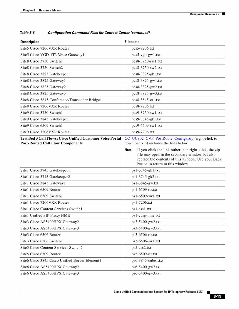
Chapter 8 Resource Library Component Resources
Site5 Cisco 7206VXR Router pcs5-7206.txt
Site5 Cisco VGD-1T3 Voice Gateway1 pcs5-vgd-gw1.txt
Site8 Cisco 3750 Switch1 pcs8-3750-sw1.txt
Site8 Cisco 3750 Switch2 pcs8-3750-sw2.txt
Site8 Cisco 3825 Gatekeeper1 pcs8-3825-gk1.txt
Site8 Cisco 3825 Gateway1 pcs8-3825-gw1.txt
Site8 Cisco 3825 Gateway2 pcs8-3825-gw2.txt
Site8 Cisco 3825 Gateway3 pcs8-3825-gw3.txt
Site8 Cisco 3845 Conference/Transcoder Bridge1 pcs8-3845-ct1.txt
Site8 Cisco 7206VXR Router pcs8-7206.txt
Site9 Cisco 3750 Switch1 pcs9-3750-sw1.txt
Site9 Cisco 3845 Gatekeeper1 pcs9-3845-gk1.txt
Site9 Cisco 6509 Switch1 pcs9-6509-sw1.txt
Site9 Cisco 7206VXR Router pcs9-7206.txt
Test Bed 3 Call Flows: Cisco Unified Customer Voice Portal Post-Routed Call Flow Components
CC_UC802_CVP_PostRoute_Configs.zip (right-click to download zip) includes the files below.
Note If you click the link rather than right-click, the zip file may open in the secondary window but also replace the contents of this window. Use your Back button to return to this window.
Site1 Cisco 3745 Gatekeeper1 ps1-3745-gk1.txt
Site1 Cisco 3745 Gatekeeper2 ps1-3745-gk2.txt
Site1 Cisco 3845 Gateway1 ps1-3845-gw.txt
Site1 Cisco 6509 Router ps1-6509-rtr.txt
Site1 Cisco 6509 Switch1 ps1-6509-sw1.txt
Site1 Cisco 7206VXR Router ps1-7206.txt
Site1 Cisco Content Services Switch1 ps1-css1.txt
Site1 Unified SIP Proxy NME ps1-cusp-nme.txt
Site3 Cisco AS5400HPX Gateway2 ps3-5400-gw2.txt
Site3 Cisco AS5400HPX Gateway3 ps3-5400-gw3.txt
Site3 Cisco 6506 Router ps3-6506-rtr.txt
Site3 Cisco 6506 Switch1 ps3-6506-sw1.txt
Site5 Cisco Content Services Switch2 ps5-css2.txt
Site5 Cisco 6509 Router ps5-6509-rtr.txt
Site6 Cisco 3845 Cisco Unified Border Element1 ps6-3845-cube1.txt
Site6 Cisco AS5400HPX Gateway2 ps6-5400-gw2.txt
Site6 Cisco AS5400HPX Gateway3 ps6-5400-gw3.txt
Table 8-6 Configuration Command Files for Contact Center (continued)
Description Filename
8-19Cisco Unified Communications System for IP Telephony Release 8.0(2)

Chapter 8 Resource Library Unified Communications Demos
Configuration Command Files for IP Telephony
Table 8-7 describes the contents of a ZIP file with sample IP telephony configurations that you can download. Each ZIP file contains text files that contain the output from issuing a show running-config IOS command on various components in the IP telephony tested deployments.
Unified Communications DemosTools are available to demonstrate the collaboration features of a Cisco Unified Communications System:
• For Cisco partners: Cisco Remote Demonstrations for Partners
• For Cisco sales teams: Global Customer Demonstrations [Internal]
Site6 Cisco AS5400HPX Gateway4 ps6-5400-gw4.txt
Site6 Cisco AS5400HPX Gateway5 ps6-5400-gw5.txt
Site6 Cisco PSTN/VXML Gateway2 ps6-pstn-vxml-gw2.txt
Site8 Cisco 3845 SIP VXML Gateway1 (with Unified Presence)
ps8-3845-gw1-vxml-cup.txt
Site8 Cisco PSTN Gateway1 (with Unified Presence) ps8-pstn-gw1-cup.txt
Table 8-6 Configuration Command Files for Contact Center (continued)
Description Filename
Table 8-7 Configuration Command Files for IP Telephony
Description Filename
Zip file includes Cisco device configurations listed below:
Note Some parameters, such as passwords, have been removed from the configuration files for security reasons.
IPT_UC802_Configs.zip (right-click to download zip) includes the files below.
Note If you click the link rather than right-click, the zip file may open in the secondary window but also replace the contents of this window. Use your Back button to return to this window.
Paris (CDG) Remote Site Router CDG-2801.txt
Paris (CDG) IP-to-IP Gateway Configured for Cisco Unified Communications Manager Express
CDG-CME-IPIPGW.txt
Geneva (GVA) Primary Voice Gatekeeper GVA-Voice-GK.txt
London (LGW) IP-to-IP Gateway for Cisco Unified Communications Manager
LGW-GK-IPIPGW.txt
Remote Site on a Cisco 3750 Remote-3750.txt
Warsaw (WAW) Cisco Unified Communications Manager Express on a Cisco 3845
WAW-3845-CME.txt
8-20Cisco Unified Communications System for IP Telephony Release 8.0(2)
Chapter 8 Resource Library System Compatibility Tool
System Compatibility ToolThe Cisco Unified Communications Compatibility Tool provides tables that identify the compatible software release versions for each product element in each Cisco Unified Communications release.
Ordering GuidesOrdering guides for most Cisco Unified Communications products are available for Cisco partners, Cisco sales staff, and Cisco service providers.
End-of-Sale and End-of-Life ProductsThe end-of-sale (EOS) date is the last date to order the product through Cisco point-of-sale mechanisms. The product is no longer for sale. There is also an end-of-life (EOL) process that guides the final business operations associated with the product life cycle.
The EOL process consists of a series of technical and business milestones and activities that, once completed, make a product obsolete. Once obsolete, the product is not sold, manufactured, improved, repaired, maintained, or supported.
For information about recommended replacements, see the comprehensive list of announcements at the following URL:
http://www.cisco.com/en/US/products/prod_end_of_life.html
For information on specific products, choose a product from the following URL:
http://www.cisco.com/en/US/products/sw/voicesw/index.html
Then click on the End-of-Life and End-of-Sale Notices link in the Product Literature section.
For an overview of the Products and Services EOL policy, see the information at the following URL:
http://www.cisco.com/en/US/products/products_end-of-life_policy.html
Cisco Unified Workspace LicensingCisco Unified Workspace Licensing is an easy, affordable program for procurement of a broad range of Cisco Unified Communications applications and services. Unified Workspace Licensing facilitates consistent deployment of multiple applications to all users in their workspaces and helps organizations maximize the potential of unified communications.
This program streamlines pricing, licensing, and deployment of Cisco Unified Communications solutions and enables organizations to implement a media-rich unified communications experience at a cost-effective user basis.
8-21Cisco Unified Communications System for IP Telephony Release 8.0(2)

Chapter 8 Resource Library Documentation Wiki
Documentation WikiThe Cisco documentation wiki (DocWiki) contains information on a number of Cisco product-related topics. Among these is a category for Cisco Unified Communications Systems, which currently includes topics for:
• Unified Communications System Design: This topics includes information and tutorials on design tools such as the Cisco Unified Communications Sizing Tool, which can be used to design and model solutions for existing and prospective customers.
• Unified Communications System Implementation: This topic includes information on configuring system components, and provides detailed configuration examples based on tested deployment models.
• Unified Communications System Operations: This topic includes information on the tasks you need to perform to maintain and optimize your system and keep it operating as trouble-free as possible. These tasks are broken down into two areas: one-time and infrequent tasks, and regular and scheduled tasks.
• Unified Communications System Troubleshooting: This topic includes information that will assist you with isolating and resolving problems you may have with Unified Communications system components. This topic offers sections for system troubleshooting methodology and commonly encountered problems.
• Unified Communications Virtualization: This topic includes information on running Unified Communications applications on a virtual machine in a Unified Computing System (UCS) environment.
For additional Cisco Unified Communications topics posted on the Cisco documentation wiki, see http://docwiki.cisco.com/wiki/Cisco_Unified_Communications.
8-22Cisco Unified Communications System for IP Telephony Release 8.0(2)

Cisco Unified Com
C H A P T E R 9
Training LibraryUsing the Training LibraryThis tab includes training resources to help you learn more about Cisco Cisco Unified Communications. The training resources are organized by audience:
• General Training contains links to courses and videos on demand (VoDs) for a general audience.
• Training Available to Partners contains resources for Cisco authorized partners and resellers.
• Training Available to Cisco Employees contains resources available for internal use only.
These categories list both online and instructor-led courses, downloadable VoDs, and links to online events and webcasts.
Play the short Cisco Unified Communications Simulation Challenge to see if you can become a champion migrator.
General TrainingThese Cisco training websites provide training on all Cisco products and technologies and are available to a general audience.
• The Cisco Learning Network
• Global Learning Locator
• Featured Virtual Events and Webcasts
• Cisco Press self-study resources
Training Available to PartnersCisco offers a variety of training resources to partners. This topic describes some courses that are specific to Cisco Unified Communications System Release 8.0(2).
Some Cisco Unified Communications training VoDs are available from the Cisco Unified Communications System Release 8 Technical Readiness page. Click the Tools & Training tab on the readiness page for more information on partner training.
For training information on all Cisco products and technologies, see the following sites.
9-1munications System for IP Telephony Release 8.0(2)
Chapter 9 Training Library Using the Training Library
Note To access these sites, you must be registered as an employee of a Cisco Channel Partner company.
• Partner Education Connection
• Global Learning Partner Locator
Partner Education Connection Courses
Partner Education Connection (PEC) courses are the primary learning source for Cisco Channel Partners. PEC provides training on products, tools, and solutions.
Use the following e-learning modules for information on the Cisco Unified Communications system:
• QuickStart
These web-based modules prepare partners to sell Cisco Unified Communications System solutions. This course covers selling strategies, pricing, and customer testimonials.
• Partner Beta Training
The PEC site contains a VoD which provides information on what is new in the latest Cisco Unified Communications System.
• Cisco Unified Communications Architecture and Design
These web-based modules address identifying the features of the Cisco Unified Communications system and teaching the Cisco methodology for implementing voice over data networks.
Cisco Learning Partner Courses
Training from Cisco Learning Partners provides a comprehensive set of training resources, from instructor-led courses to remote access labs and e-learning solutions. These companies are the only organizations to employ Certified Cisco Systems Instructors and deliver Cisco authorized and approved content, including product-specific training, technology training, and certification-preparation courses.
Cisco Unified Communications Courses
This section contains descriptions of Cisco Unified Communications courses for account managers, systems engineers, and other sales personnel.
ASPIRE Cisco Unified Communications Workshops
For more information on APSIRE workshops, go to http://www.aspiregroup.com/knowledge_center.html.
ANI Cisco Unified Communications Courses
• Cisco Unified Communications Deep Dive Application Selling
The challenge for the Cisco and partner account teams is to understand the relationship between technology solutions, business processes, and keys to customer business success. The Cisco Unified Communications portfolio provides structure and intelligence to business communications, enabling organizations to streamline and integrate their communications more closely with business processes, making them more competitive in their market. Cisco Unified Communications Deep Dive Application Selling teaches the account manager how to become the critical link between
9-2Cisco Unified Communications System for IP Telephony Release 8.0(2)

Chapter 9 Training Library Using the Training Library
customer issues and Cisco solutions by recognizing the critical success factors of customer stakeholders and relating the Cisco Unified Communications solutions to the achievement of these factors. Click the course name above for a full course description and information on how to register.
Training Available to Cisco EmployeesCisco offers a variety of training resources to employees. These Cisco Unified Communications system launch page and training websites provide training on all Cisco products and technologies:
• Partner Education Connection
• Global Learning Partner Locator
• Cisco Unified Communications System Release 8 Technical Readiness
9-3Cisco Unified Communications System for IP Telephony Release 8.0(2)

Chapter 9 Training Library Using the Training Library
9-4Cisco Unified Communications System for IP Telephony Release 8.0(2)
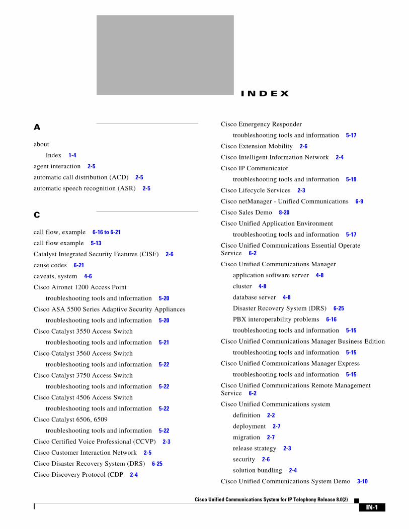
Cisco Unified Com
I N D E X
A
about
Index 1-4
agent interaction 2-5
automatic call distribution (ACD) 2-5
automatic speech recognition (ASR) 2-5
C
call flow, example 6-16 to 6-21
call flow example 5-13
Catalyst Integrated Security Features (CISF) 2-6
cause codes 6-21
caveats, system 4-6
Cisco Aironet 1200 Access Point
troubleshooting tools and information 5-20
Cisco ASA 5500 Series Adaptive Security Appliances
troubleshooting tools and information 5-20
Cisco Catalyst 3550 Access Switch
troubleshooting tools and information 5-21
Cisco Catalyst 3560 Access Switch
troubleshooting tools and information 5-22
Cisco Catalyst 3750 Access Switch
troubleshooting tools and information 5-22
Cisco Catalyst 4506 Access Switch
troubleshooting tools and information 5-22
Cisco Catalyst 6506, 6509
troubleshooting tools and information 5-22
Cisco Certified Voice Professional (CCVP) 2-3
Cisco Customer Interaction Network 2-5
Cisco Disaster Recovery System (DRS) 6-25
Cisco Discovery Protocol (CDP 2-4
Cisco Emergency Responder
troubleshooting tools and information 5-17
Cisco Extension Mobility 2-6
Cisco Intelligent Information Network 2-4
Cisco IP Communicator
troubleshooting tools and information 5-19
Cisco Lifecycle Services 2-3
Cisco netManager - Unified Communications 6-9
Cisco Sales Demo 8-20
Cisco Unified Application Environment
troubleshooting tools and information 5-17
Cisco Unified Communications Essential Operate Service 6-2
Cisco Unified Communications Manager
application software server 4-8
cluster 4-8
database server 4-8
Disaster Recovery System (DRS) 6-25
PBX interoperability problems 6-16
troubleshooting tools and information 5-15
Cisco Unified Communications Manager Business Edition
troubleshooting tools and information 5-15
Cisco Unified Communications Manager Express
troubleshooting tools and information 5-15
Cisco Unified Communications Remote Management Service 6-2
Cisco Unified Communications system
definition 2-2
deployment 2-7
migration 2-7
release strategy 2-3
security 2-6
solution bundling 2-4
Cisco Unified Communications System Demo 3-10
IN-1munications System for IP Telephony Release 8.0(2)

Index
Cisco Unified Contact Center Express
troubleshooting tools and information 5-16
Cisco Unified IP Phone
advertising presence 2-4
power methods 2-4
traffic markings 2-4
Cisco Unified IP phone
troubleshooting 6-11
Cisco Unified MeetingPlace
overview 2-5
troubleshooting tools and information 5-17
Cisco Unified Mobile Communicator
troubleshooting tools and information 5-20
Cisco Unified Mobility Advantage
troubleshooting tools and information 5-20
Cisco Unified Operations Manager 6-6
troubleshooting tools and information 5-21
Cisco Unified Personal Communicator
overview 2-5
troubleshooting tools and information 5-19
Cisco Unified Presence
troubleshooting tools and information 5-17
Cisco Unified Presence Server
overview 2-5, 2-7
Cisco Unified Provisioning Manager 6-7
troubleshooting tools and information 5-21
Cisco Unified Service Monitor 6-7
troubleshooting tools and information 5-21
Cisco Unified Service Statistics Manager 6-8
troubleshooting tools and information 5-21
Cisco Unified SRST 4-8
troubleshooting tools and information 5-15
Cisco Unified Survivable Remote Site Telephony
See Unified SRST
Cisco Unified Video Advantage
troubleshooting tools and information 5-20
Cisco Unified Videoconferencing 2-5
Cisco Unified Wireless IP Phone 7920G
mobility 2-6
IN-2Cisco Unified Communications System for IP Telephony Release 8.
Cisco Unity
overview 2-5
troubleshooting tools and information 5-18
Cisco Unity Connection
troubleshooting tools and information 5-18
Cisco Unity Express
troubleshooting tools and information 5-18
committed information rate (CIR) 6-15
components
upgrading 5-3
configuration files 8-17
D
deployment
overview 2-7
design guides 3-6
design guides, SRND 4-2
design tasks
define secutiry policies 4-7
review tested site models 4-6
system caveats 4-6
system test results 4-6
design tools
Cisco CallManager Capacity Tool 4-2
IPC Resource Calculator 4-3
device, advertising presence 2-4
diagrams
Visio 8-5, 8-6
Digital Signal Processor (DSP) status 6-13
disconnect reason/cause codes 6-21
downloadable Visio diagrams 8-5, 8-6
E
emergency caller response 2-6
employee training 9-3
encryption
media encryption 2-6
0(2)
Index
signaling encryption 2-6
end-of-life 8-21
end-of-sale 8-21
F
firewall 2-6, 6-13
frame check sequence (FCS) errors 6-15
H
high availability 2-7
design 4-7
I
Index
using 1-4
integration
with existing equipment 2-7
with existing network 2-7
intelligent contact routing 2-5
interactive voice response (IVR) 2-5
IP telephony overview 2-8
J
jitter 6-15
K
keepalive mechanism 4-8
L
links
login required 1-5
restricted access 1-5
login required
Cisco Uni
links 1-5
M
maintenance support 6-2
major release 2-3
media encryption 2-6
messaging
overview 2-5
Microsoft Visio 8-8
migration, to Cisco Unified Communications system 2-7
minor release 2-3
mobility
Cisco Extension Mobility 2-6
overview 2-6
site and campus mobility 2-6
monitoring the system 6-2
monitoring tools 6-5
N
Network Address Translation (NAT) 6-13
network management 6-1
Cisco netManager - Unified Communications 6-9
Cisco Unified Operations Manager 6-6
Cisco Unified Provisioning Manager 6-8
Cisco Unified Service Monitor 6-7
Cisco Unified Service Statistics Manager 6-8
network monitoring tools 6-5
Network Time Protocol (NTP) 5-24
network topology diagram 5-13, 5-23
network topology resources 8-5
O
one-way audio problems 6-11
ordering guides 8-21
IN-3fied Communications System for IP Telephony Release 8.0(2)

Index
P
packet drops 6-14
partner training 9-1
PBX interoperability problems 6-16
planning tasks
business requirements 3-5
collect and analyze data 3-8
system components 3-7
understand deployment options 3-7
Port Address Translation (PAT) 6-13
power over Ethernet (POE) 2-4
Q
QoS 2-4, 6-15
Quote Builder Tool 3-7, 5-2
R
release matrix 3-8
release strategy
for Cisco Unified Communications system 2-3
major release 2-3
minor release 2-3
resources
network topology 8-5
restricted access
links 1-5
rich-media conferencing 2-5
S
secure platforms 2-6
security
Catalyst Integrated Security Features (CISF) 2-6
firewall integration 2-6
guides, policies 4-7
overview 2-6
IN-4Cisco Unified Communications System for IP Telephony Release 8.
phone security features 2-7
secure platforms 2-6
signaling encryption 2-6
signaling encryption 2-6
site and campus mobility 2-6
small and medium-sized business
network management 6-9
SMB
See small and medium-sized business
software versions
compatibility 5-13
solution bundling 2-4
Solution Expert 3-7, 4-3, 4-6, 5-2
SRND 3-6
supervisor interaction 2-5
synchronizing server date and time 5-24
system, monitoring 6-2
system demo 3-10
system management, service options 6-2
system management, tasks 6-1
T
testing, user acceptance 5-25
test results, system 4-6
text-to-speech (TTS) 2-5
tips
on using Visio drawings 8-8
tools, Solution Expert 3-7, 5-2
traceroute 6-11
traffic engineering 4-7
training
Cisco employees 9-3
partners 9-1
troubleshooting
common user problems 6-10
daily operations 6-10
jitter 6-15
methodology 5-10
0(2)

Index
NAT firewall traversal problems 6-13
network topology diagrams 5-23
one-way audio 6-11
PBX interoperability problems 6-16
questions to ask users 5-11
recommended trace settings 5-25
voice quality 6-14
U
upgrade
planning 3-9
user acceptance test 5-25
using
Index 1-4
Visio drawings 8-8
V
VG224 Analog Voice Gateway
troubleshooting tools and information 5-22
video telephony 2-6
Visio 8-8
Visio diagrams 8-5, 8-6
VLAN 2-4
voice quality problems 6-13
W
wireless devices 2-4
See also Cisco Unified Wireless IP Phone 7920
Cisco Uni
IN-5fied Communications System for IP Telephony Release 8.0(2)

Index
IN-6Cisco Unified Communications System for IP Telephony Release 8.
0(2)