cisco systems networking professionals … · #9 baseline initial cap sits on #18 baseline ......
TRANSCRIPT
SECOND QUARTER 2006CISCO SYSTEMS NETWORKING PROFESSIONALS MAGAZINE
Cisco Unified Communications
Changes the Way WeCommunicate
Is Your Wiring Closet Ready for
Real Time?
The ABCs of VPNs
4 Data CenterDesign Options
Lifecycle Services:
Your Roadmap to Successful
Deployments
ConnectingPeople
NotDevices
Reprinted with permission from Packet® magazine (Volume 18, No. 2), copyright © 2006 by Cisco Systems, Inc. All rights reserved.

CISCO.COM/PACKET
dept. subtitle sits on #9 baseline
initial cap sits on #18 baseline
dept. name sits on #2 baseline identifier slug sits on
#3 baseline
CISCO SYSTEMS NETWORKING PROFESSIONALS MAGAZINE
SECOND QUARTER 2006 VOLUME 18, NO. 2
COVER STORY36People Reaching PeopleWith a plethora of voice, video, and data products and native
support for SIP, Cisco Unified Communications lowers the
barriers to virtual collaboration.
FEATURES42The Network LifecycleLifecycle services offer best practices for deploying
advanced technologies on your network.
46The Connected CommunityImagine a city where government services
can be delivered anytime, anywhere and citizens
are totally connected.
48Winning the Security GameManagement and complete endpoint security
are the final pieces in a fully deployable
Self-Defending Network.
contentsK
EV
IN T
WO
ME
Y
PACKET SECOND QUARTER 2006
Reprinted with permission from Packet® magazine (Volume 18, No. 2), copyright © 2006 by Cisco Systems, Inc. All rights reserved.

CISCO.COM/PACKET PACKET SECOND QUARTER 2006
CISCO SYSTEMS NETWORKING PROFESSIONALS MAGAZINE
SECOND QUARTER 2006 VOLUME 18, NO. 2
TECH TIPS + TRAINING7 The ABCs of VPNs
A comparison of virtual private networks.
11 Deploying Cisco Security Agent
Out of the lab and into production.
21 NAC Implementation Basics
Preparing your environment for
endpoint security.
CHALK TALKBEST PRACTICES
25 Boosting Streaming Media
How enterprises can enhance
audio-video broadcast performance.
TROUBLESHOOTING
29 Static Routing
Troubleshooting static routing in redun-
dant path networks with self-tunnels.
DESIGN STRATEGY
31 Data Center Consolidation Tips
Migrating toward consolidation? Here
are some considerations and design tips.
1 From the Editor
Welcome to the New
Packet Magazine.
3 Mail
4 Datagrams
16 Reader Tips
17 Tech Tips
79 NetPro Expert
Troubleshooting the Cisco
ASA 5500 and PIX 7.0.
81 Advertiser Index
82 Cache File
departments
SERVICE PROVIDERS63 Service Control Benefits ISP
Plala Networks delivers security and
“peace of mind” to customers.
67 IMS Migration Primer for MSOs
How to transition to new multimedia and
fixed mobile applications.
BEYOND SPEEDS + FEEDS71 Storage Switch
Redefines Scalability
New Cisco MDS 9513 Switch.
72 New Product Dispatches
77 Product Review
Cisco Aironet 1300 Series
Wireless Bridge.
INFRASTRUCTURESWITCHING
55 Switching into Overdrive
Real-time applications are driving next-
generation wiring closets.
OPTICAL
59 Cisco IP over DWDM
Delivering network convergence for capa-
city growth and operational efficiencies.
Reprinted with permission from Packet® magazine (Volume 18, No. 2), copyright © 2006 by Cisco Systems, Inc. All rights reserved.

CISCO.COM/PACKET PACKET SECOND QUARTER 2006 1
RO
BB
RO
DM
AN
F R O M T H E E D I T O R
IF YOU’RE A REGULAR READER OF PACKET, YOU PROBABLY
ALREADY KNOW THAT WE’VE CHANGED more than thelook of the magazine. We have rethought and restruc-tured Packet from the ground up—improving on the bestand getting rid of the rest—to bring you what we think isthe industry’s premier magazine for Cisco networkingprofessionals. Whether you’re a newbie or an expert, anetwork administrator or IT director, you’re likely tofind something of interest in the pages of Packet.
The cover story and feature articles (see the first page of the tableof contents) highlight the latest technologies and industry trends of interest tothe general reader, regardless of industry or technical level. Feature articleshighlight the business benefits of particular networking technologies, answer-ing the “what” and “why” but not necessarily the “how” of networking. Forthat, you’ll want to turn to the “Departments” page of the table of contents.
Tech Tips+Training—Targeted to the newbie or the hands-on technical user who isnew to a particular technology, this department offers entry points into vari-ous networking technologies, primers, tech tips, and even a quiz (see page16). This section is also home to our highly popular “Reader Tips” column(see page 14).
Chalk Talk—For the more experienced networking professional, Chalk Talk articlesare often authored by experts in the field and include in-depth discussions onrouting and switching protocols, new networking standards, troubleshoot-ing, deployment strategies, and best practices
Infrastructure—This section targets both the hands-on networking professional aswell as technical managers, and focuses on systems and solutions as opposedto individual products.
Service Providers—This department highlights networking technologies, solutions,and services most relevant to telcos, ISPs, MSPs, and mobile operators.
Beyond Speeds + Feeds—This new department is all about products. It’s home to ourever-popular New Product Dispatches column, as well as longer articles thatfocus on new or existing products from Cisco and its partners. A new Product Review rounds out this department.
There are other changes, but we’ll let you discover them for yourself. We think you’regoing to appreciate the new Packet. Whether you do or don’t, or fall some-where in between, we want to hear from you. Please tell us what you think.Send an e-mail to [email protected]. P
DAVID BALL
Editor in Chief
PACKET
DAVID BALLPublisher and Editor in Chief
JENNIFER REDOVIANExecutive Editor
SUSAN BORTONManaging Editor
SUZANNE JACKSON, JOANIE WEXLERContributing Editors
ROBERT J. SMITHSunset Custom PublishingProject Manager/Account Supervisor
NICOLE COLLINS, AMY MACKEYSunset Custom Publishing Production
EMILY BURCHArt Director/Designer
ELLEN SKLAR-ABBOTTDiagram Illustrator
BILL LITTELLPrint Production Manager
VALERIE MARLIACPromotions Manager
MISHA GRAVENOR/GETTY IMAGESCover Photograph
ADVERTISING INFORMATION:Kristen Bergman, 408 [email protected]
PUBLISHER INFORMATION: Packet magazine (ISSN 1535-2439) is published quarterly by Cisco Systems.
Please send address corrections and other correspondence direct [email protected], Catalyst, CCDA, CCIE, CCNA, Cisco, Cisco IOS,
Cisco Networking Academy, Cisco Press, the Cisco
Powered Network logo, the Cisco Systems logo, Cisco
Unity, IOS, iQ, Linksys, Packet, and PIX are registered
trademarks or trademarks of Cisco Systems, Inc.,
and/or its affiliates in the USA and certain other coun-
tries. All other trademarks mentioned in this publica-
tion are the property of their respective owners.
Packet copyright © 2006 by Cisco Systems, Inc.
All rights reserved. Printed in the USA.
No part of this publication may be reproduced in
any form, or by any means, without prior written per-
mission from Cisco Systems, Inc.
This publication is distributed on an “as-is” basis,
without warranty of any kind either express or implied,
including but not limited to the implied warranties of
merchantability, fitness for a particular purpose, or
noninfringement. This publication could contain tech-
nical inaccuracies or typographical errors. Later issues
may modify or update information provided in this
issue. Neither the publisher nor any contributor shall
have any liability to any person for any loss or damage
caused directly or indirectly by the information con-
tained herein.
This magazine is printed on recycled paper.
10%TOTAL RECOVERED FIBER
Welcome to the New PacketMagazine
Reprinted with permission from Packet® magazine (Volume 18, No. 2), copyright © 2006 by Cisco Systems, Inc. All rights reserved.

CISCO.COM/PACKET PACKET SECOND QUARTER 2006 3
mailLong-Lasting RoutersI have seen numerous letters aboutuptime on routers in your past fewissues. I couldn’t help but notice thatone of those readers was running CiscoIOS Software Release 12.1(2). Appar-ently, these folks are not keeping theirrouters up to date in response to all thevulnerability notices. If it were not forthe vulnerability upgrades, 90 percentof my routers would be up for 3 to 4years or more, too. It seems that a vul-nerability is detected once or twice ayear, making it necessary for me toupgrade more than 350 devices.
JAY E. DONOUGH
Verizon Harrisburg
Pennsylvania, USA
EDITOR’S NOTE We have received letters
from other readers with valid concerns
about network security. As reader
Matt Carter pointed out, “In the UNIX
world, uptime only reflects stability to a
critical point, beyond which it just
advertises to the world that you are
running insecure systems.”
Info on WAN Switches?I have been a regular reader of Packet
for many years, and would like torequest that you include informationand tech tips on Cisco WAN switcheslike the IGX and MGX. Many of mycolleagues need more hands-on tips onCisco WAN switches.
SANGAMESHWARA P.C.
Infosys Technologies Ltd.
Bangalore, India
EDITOR’S NOTE For switching support
information, visit cisco.com/packet/182_2a1.
The WAN switches area of this web page
includes links to information that you may
find helpful.
Littlest Packet ReaderI thought you might want to see thatyour readers are getting younger andyounger. My daughter, Esther, at 9months just can’t put down my Packet
magazine. She assures me that it is morethan the brightly colored advertisementsthat she is interested in.
SCOTT DENHOLM
New Plymouth, New Zealand
Mixed Reviews for DigitalI have some concerns about your newdigital version. I am a longtime print sub-scriber, and have enjoyed the PDF versionof your magazine. I regularly downloadthe PDF and use Adobe Acrobat exten-sively to make bookmarks, notes, high-lights, etc. Then I send the PDF out to mynetwork engineer peers so that they canadd notes after trying out an implementa-tion of something that they saw in Packet.This facilitates information transfer, andit is very easy to copy and paste informa-tion such as commands and scriptsdirectly out of the PDF.
After reading the online digital versionand downloading it to my PC, I found itimpossible to use the same workflow. Theformat has these shortcomings:1. Lack of tools in Macromedia (now
Adobe) Flash
2. Size of file, which is 4 to 5 times larger than a PDF
3. Inability to download .EXE files from the Internet and execute them (becauseof corporate security policies)I hope that Cisco continues to offer
the PDF version of its fine magazine.LUIZ DE PAULA JR.
TGS Management Corporation
Irvine, California, USA
EDITOR’S NOTE Thank you for your
concerns. A PDF version is now available
for back issues of Packet from 2004 to the
present at cisco.com/packet/182_2a2.
I am a new subscriber to your digitaledition, and I want to thank Cisco forproviding information about new prod-ucts and innovations. Having access tothe digital version saves me from thestress that physical mailing causes inthis part of the world. Cisco has onceagain proven to be responsive to enthu-siasts like me.
KAYODE AFOLABI
A2International
Ilorin, Nigeria
SEND YOUR COMMENTS TO PACKET
We welcome your comments and questions. Reach us through e-mail [email protected]. Be sure toinclude your name, company affiliation,and e-mail address. Letters may be edited for clarity and length.NOTE: The Packet editorial staff cannot provide help-desk services.
Reprinted with permission from Packet® magazine (Volume 18, No. 2), copyright © 2006 by Cisco Systems, Inc. All rights reserved.

PACKET SECOND QUARTER 2006 CISCO.COM/PACKET4
datagramsNetworking the Ocean In the same way that Internetaccess is an integral part ofnearly every research lab andoffice on land, extending that access to laboratoriesinstalled at sea is revolution-izing the way marine sciencewill be conducted in thecoming decades.
Internet-connected oceanobservatories are already areality at the Woods HoleOceanographic Institution(WHOI), where oceanogra-phers can sit in their labsashore and communicatewith instruments in the water,analyzing events such as
hurricanes and earthquakes. For its cyberinfrastructure,
WHOI, a private, independ-ent marine research, engineer-ing and higher educationorganization in Falmouth,Massachusetts, deploys aCisco-enabled LAN thatincludes a redundant corenetwork of Cisco Catalystswitches and Cisco routers. A Cisco wireless network alsooverlays most of the WoodsHole campus. The networkprovides connections to boththe Internet and Internet 2.
WHOI operates an oceanobservatory that includes a
shore station, underwaternode, and offshore monitor-ing tower—all linked andconveyed ashore by an under-sea fiber-optic cable. Theinstitution’s three ocean-going vessels also have LANswith Internet access.
WHOI Senior ScientistAlan Chave is principal scientist for the Laboratoryfor the Ocean ObservatoryKnowledge Integration Grid(LOOKING), a collaborativeproject of several scientificinstitutions for experimentalwireless, optical networks,and grid technology. Throughthe project, communities ofoceanographers will be linkedvia high-speed wireless andoptical networks to observa-tories off the coasts of the USand Canada.
With LOOKING, Chavesays, “Scientists worldwidewill be able to access dataon this growing global net-work, making much moreinformation available toscientists, teachers, students,and the public.”
For more on the LOOK-ING project and otherWHOI research and activi-ties, visit www.whoi.edu. P
AIR-SEA INTERACTION TOWER, Martha’s Vineyard Coastal Observatory, Woods Hole Oceanographic Institution.
JAY
NE
DO
UC
ET
TE
, W
OO
DS
HO
LE
OC
EA
NO
GR
AP
HIC
IN
ST
ITU
TIO
N
Reprinted with permission from Packet® magazine (Volume 18, No. 2), copyright © 2006 by Cisco Systems, Inc. All rights reserved.

speaker phone. The menusare easy to navigate, allowing you to manageSkype remotely from the handset, which supportsa variety of features for calling and messaging. Find more information atcisco.com/packet/182_3c1. P
Acquired
SyPixx Networks, Inc.
Employees
26
Location
Waterbury,Connecticut,USA
Recently Announced Cisco Acquisitions
Network-centric video surveillance soft-ware and hardware that enable existinganalog video surveillance systems tooperate as part of an open IP network.This acquisition will enable Cisco todeliver video surveillance as part of anintelligent converged environment.
As a result of this acquisition, physicalsecurity will become a new emergingtechnology area for Cisco.
SLEEK AND PRACTICAL
The Linksys CIT200 includes a cordless handset, charger, andbase station that connects to a USB port on a PC.
CISCO.COM/PACKET PACKET SECOND QUARTER 2006 5
How Does Cisco Do IT?
See how the latest IP networking technologies
have been implemented at Cisco, by watching a
new Cisco on Cisco TechnologySeminar on your PC.
Part of the Cisco IT@Work program, these one-hour video
seminars offer insight into Cisco IT’s own deployment of
Cisco IP networking technologies—with leadingCisco experts relating how
Cisco designs, deploys, and manages its own products
and solutions.Gain insight from lessonslearned at Cisco and find
best practices for a range of current technologies,including application-oriented
networking (AON), IP telephony, wireless LANs, data
center design, security, storage-area networking, and
more. Downloadable presentations on these topics
are also available.cisco.com/packet/182_3d1. P
Convenient NewLinksys Cordless Internet Phone with SkypeSkype Internet calling isbecoming as convenient asregular phone service withthe recent introduction of theLinksys Cordless InternetTelephony Kit (CIT200)—aSkype phone from Linksys.
The sleek Linksys CIT200uses a wireless DECT basestation connected to the PCvia a USB port to untetherthe handset from the com-puter. The Linksys CIT200 isa pleasure to hold, has avibrant color screen, andoffers excellent audio quality,even when using the built-in
FREE
SMART BUSINESS GUIDE
FOR SMALL AND
MIDSIZED BUSINESSES
LEARN HOW THE networks from Cisco can deliver newways of doing business for your small or midsized business. Download your Smart Business Guide, an
in-depth look at how Cisco SmartBusiness Communications can helpyou take advantage of the net-work to strengthen your businessin new ways. To learn more,visit cisco.com/youinc. P
Reprinted with permission from Packet® magazine (Volume 18, No. 2), copyright © 2006 by Cisco Systems, Inc. All rights reserved.

CISCO.COM/PACKET PACKET SECOND QUARTER 2006 7
irtual private networks have long allowed the provisioning of private network services across a shared public infrastructure such as the Internet or other WAN backbone.Over the years, however, the proliferation of VPN protocols and technologies, has made it challenging to differentiate between various VPN types and understand how they compare. • A wealth of technologiesenable both site-to-site VPNs and remote access VPNs. Site-to-site VPNs allow connectivity between fixed,geographically dispersed sites (such as a head office and branch offices). Remote access VPNs allow mobileor home-based users to access an organization’s data or other resources. • In both types of VPN, tunnels arecreated between locations by encapsulating users’ traffic within other packets. For this to happen, the tunneled (encapsulated) traffic gains additional header(s),tags, or labels that correspond to the tunneling protocol.Through the encapsulation with an additional packet header,tags, or labels, a VPN gateway, customer edge (CE) device, orprovider edge (PE) device can distinguish among customers or users. Therefore, tunneling keeps each organization’s oruser’s traffic separate, and thus private, from other trafficflowing on a shared network.
Data encryption can be added to the mix to scramble datain transit for extra security. This happens frequently when theWAN used for VPN transport is the public Internet, whichdoes not fall under the operational control of a single serviceprovider and is thus considered an “untrusted” network.Many organizations that use network services offered across acarrier’s backbone, such as Frame Relay, ATM, and Multipro-tocol Label Switching (MPLS)-based services, opt not to useencryption, because carriers use Layer 2 virtual circuits,labels, or similar technologies to separate customer traffic.These VPNs are called trusted VPNs.
In a secure VPN, by contrast, customer data traffic isauthenticated and encrypted. Examples of secure VPNs are IPSecurity (IPsec) VPNs, Secure Sockets Layer (SSL) VPNs, andLayer 2 Tunneling Protocol (L2TP) VPNs secured using IPsec.
In site-to-site VPNs, data traffic is either tunneled betweenCE routers or between the public network service operator’sPE routers. The difference is that in a CE-to-CE configuration,the VPN tunnels and associated security extend across theWAN to the customer premises. In a PE-to-PE configuration,
The ABCs of VPNsA COMPARISON OF VIRTUAL PRIVATE NETWORKS by mark lewis
V
T E C H T I P S + T R A I N I N G
TUNNELINGALLOWS
organizations to keep data
ccnfidential by erecting
a virtual private network.
GE
TT
Y I
MA
GE
S
Reprinted with permission from Packet® magazine (Volume 18, No. 2), copyright © 2006 by Cisco Systems, Inc. All rights reserved.
PACKET SECOND QUARTER 2006 CISCO.COM/PACKET
T E C H T I P S + T R A I N I N G
the tunnels are confined to the interior of the shared serviceprovider network.
Service provider–provisioned site-to-site VPNs can be usedto tunnel either Layer 2 or Layer 3 protocols. Technologies suchas L2TP version 3 and Any Transport over MPLS (AToM) canbe used to tunnel a variety of protocols such as Point-to-PointProtocol (PPP), Frame Relay, ATM, and Ethernet, while IEEE802.1Q tunneling (Q-in-Q) can be used to tunnel Ethernet only.IPsec, Generic Routing Encapsulation (GRE), and MPLS arecommonly used to tunnel IP or other Layer 3 protocols.
• Layer 2 site-to-site VPNs—These allow data-link-layerconnectivity between separate sites and can be provisionedbetween switches, hosts, and routers. Communication is basedon Layer 2 addressing, and PE devices forward customer net-work traffic based on incoming link and Layer 2 header infor-mation, such as a MAC address or a Frame Relay Data LinkConnection Identifier (DLCI).
AToM (Draft Martini) and L2TPv3 pseudowires (emulatedcircuits) can provide the Layer 2 protocol point-to-point trans-port necessary to enable Virtual Private Wire Service (VPWS)Layer 2 site-to-site VPNs. AToM transports Layer 2 frames
across an MPLS network, with the Label Distribution Protocol(LDP) signaling pseudowire capabilities and attributes, includ-ing a virtual circuit (VC) label that is used to distinguish Layer2 traffic associated with different customer last-mile attachmentcircuits. L2TPv3 provides similar signaling capabilities, anduses “Session IDs” and cookies to associate customer Layer 2traffic with appropriate attachment circuits. While VPWS Layer2 VPNs provide point-to-point connectivity, Virtual PrivateLAN Service (VPLS) and IP-Only LAN Service (IPLS) Layer 2VPNs are required for multipoint (any-to-any) connectivity.VPLS and IPLS take advantage of technologies such as MPLSand L2TPv3 pseudowires, as well as IEEE 802.1Q tunneling toallow multipoint Ethernet and IP-only connectivity respectively.
• Layer 3 site-to-site VPNs—These interconnect hosts androuters at separate customer sites. Customer hosts and routerscommunicate based on network-layer addressing, and PEdevices forward customer traffic based on the incoming linkand on the addresses in the IP header.
8
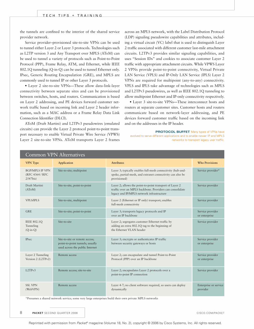
Common VPN AlternativesVPN Type Application Attributes Who Provisions
BGP/MPLS IP VPN(RFC 4364 / RFC 2547bis)
Site-to-site; multipoint Layer 3; typically enables full-mesh connectivity (hub-and-spoke, partial-mesh, and extranet connectivity can also be provisioned)
Service provider*
Draft Martini (AToM)
Site-to-site, point-to-point Layer 2; allows the point-to-point transport of Layer 2traffic over an MPLS backbone. Providers can consolidate legacy and IP/MPLS network infrastructure
Service provider
VPLS/IPLS Site-to-site, multipoint Layer 2 (Ethernet or IP only) transport; enables full-mesh connectivity
Service provider
GRE Site-to-site; point-to-point Layer 3; transports legacy protocols and IP over an IP backbone
Service provider or enterprise
IEEE 802.1Q Tunneling(Q-in-Q)
Site-to-site Layer 2; segregates customer Ethernet traffic byadding an extra 802.1Q tag to the beginning ofthe Ethernet VLAN header
Service provider
IPsec Site-to-site or remote access; point-to-point tunnels; usually used across the public Internet
Layer 3; encrypts or authenticates IP traffic between security gateways or hosts
Service provideror enterprise
Layer 2 Tunneling Version 2 (L2TPv2)
Remote access Layer 2; can encapsulate and tunnel Point-to-Point Protocol (PPP) over an IP backbone
Service provideror enterprise
L2TPv3 Remote access; site-to-site Layer 2; encapsulates Layer 2 protocols over a point-to-point IP connection
Service provider
SSL VPN(WebVPN)
Remote access Layer 4-7; no client software required, so users can deploy dynamically
Enterprise or service provider
*Presumes a shared network service; some very large enterprises build their own private MPLS networks
PROTOCOL BUFFET Many types of VPNs haveevolved to serve different applications and to enable newer IP and MPLS
networks to transport legacy user traffic.
Reprinted with permission from Packet® magazine (Volume 18, No. 2), copyright © 2006 by Cisco Systems, Inc. All rights reserved.

CISCO.COM/PACKET
BGP/MPLS IP VPNs, based on IETF RFC 4364 (formerlyRFC 2547bis), is a Layer 3 VPN technology typically provi-sioned by service providers in which the PE devices maintainseparate routing and forwarding tables for each VPN. Customerroutes are advertised between PE devices using the Multiproto-col Border Gateway Protocol (MP-BGP), and customer addressspace and routes are distinguished using BGP attributes.
An alternative to the BGP/MPLS VPN is the Virtual RouterVPN, based on an IETF draft called “Network based IP VPNArchitecture using Virtual Routers” (cisco.com/packet/182_
4b1). Here, completely separate logical routers are maintainedon the PE devices for each VPN. Each logical router maintainsits own entirely separate routing protocol instances.
Remote Access VPNs
PROTOCOLS AND TECHNOLOGIES that enable remoteaccess VPNs include IPsec, L2TP, and SSL/TLS. IPsec and
(client-initiated) L2TP remote access VPNs require client soft-ware to be installed on remote user devices, and allow connec-tivity and access to central site resources similar to thatexperienced by users physically located at the central site.
SSL VPNs (called WebVPNs in Cisco vernacular) can bequickly deployed, because they require no installation andmaintenance of special client-side software and they offer application-layer access control. This dynamic capabilityenables mobile users and users in disaster situations to accessthe network from any browser-enabled client device withInternet access.
SSL provides digital certificate–based authentication,integrity checking, and confidentiality. Transport-layer confi-dentiality is supported through secret key cryptography.
When using a clientless SSL VPN, the encrypted connectionbetween the remote user and the VPN gateway happens via aWeb connection at the application layer. This trait allowsenterprises to set up granular rules for which applications agiven user can access, depending on what type of connection isin use, the user’s access rights, and so forth. This differs fromthe Layer 3 network tunnel of an IPsec VPN, which gives allauthenticated users access to all resources unless specific accesspolicies are set up. If additional resource access is required withSSL VPNs, however, dynamically downloaded client softwarecan be installed on remote users’ workstations, and will enable“full” network access similar to that provided by IPsec remoteaccess VPNs.
For organizations that require both SSL VPNs and IPsecVPNs, Cisco VPN gateways, including the VPN 3000 SeriesConcentrator and the newer Cisco ASA 5500 Series AdaptiveSecurity Appliance, will terminate both types. The ASA 5500,which was recently enhanced, combines these VPN serviceswith firewall, intrusion prevention, and network antivirus
services in a single appliance (seestory, page 48).
Who Provisions?
CU S T O M E R - P R O V I S I O N E D,site-to-site VPNs are config-
ured on CE devices such asrouters, firewalls, and VPN con-centrators. In this case, tunnels areconfigured between CE devices inthe VPN, and customer data traf-fic is sent over these tunnels.
In CE-based Layer 3 VPNs, PEdevices do not participate in (andare unaware of) customer network routing. Rather, they for-ward customer traffic based on globally unique addressing. Inthis case, tunnels are configured between CE devices using pro-tocols such as IPsec and GRE. This configuration is sometimesknown as an overlay VPN. Examples of overlay VPNs includethose built using Frame Relay or ATM virtual circuits, as wellas those built using GRE or IPsec tunnels.
When the PE devices do participate in CE routing, the con-figuration is known as a peer VPN. In peer VPNs, routes areexchanged between CE devices and PE devices. Peer VPNs areprovisioned by the service provider.
Attributes to Consider
WHEN COMPARING BOTH PROVIDER- and customer-pro-visioned site-to-site VPNs, consider these factors:
• Connectivity—Is point-to-point or multipoint connectivityinherent to the VPN? For example, BGP/MPLS IP VPN servicesare inherently multipoint (assuming a ”typical” configuration),while IPsec and GRE VPNs are point-to-point technologies.These characteristics affect the ease of deploying a range of net-work topologies, such as full mesh, hub-and-spoke, and partialmesh. Point-to-point VPNs require building the topology out ofmultiple point-to-point tunnels, while multipoint VPNs areinherently meshed.
• Geographic reach—Is geographic reach limited to a serviceprovider backbone, or can it be extended across the Internet?MPLS-based VPNs, including BGP/MPLS IP VPNs and DraftMartini VPNs, generally limit traffic to within the perimeter ofone or more carrier’s backbone networks. By contrast, Layer 3IPsec and GRE networks can traverse private IP and publicInternet links.
• Security—Transporting MPLS Layer 3 and L2TP-basedVPN traffic over IPsec boosts their security from good to excel-lent. L2TPv3 on its own can employ tunnel authentication, anda cookie enables resistance to blind insertion attacks.
• Inherent multicast support—Can multicast traffic be
PACKET SECOND QUARTER 2006 9
• Comparing, Designing,
and Deploying VPNs
cisco.com/packet/182_4b2
• Troubleshooting Virtual
Private Networks
cisco.com/packet/182_4b3
• Cisco ASA 5500 Series
cisco.com/packet/182_4b4
• Cisco VPN 3000 Concentrators
cisco.com/packet/182_4b5
Further Reading
Reprinted with permission from Packet® magazine (Volume 18, No. 2), copyright © 2006 by Cisco Systems, Inc. All rights reserved.
PACKET SECOND QUARTER 2006 CISCO.COM/PACKET
T E C H T I P S + T R A I N I N G
natively supported across the VPN? The answer is “yes” withLayer 2 VPNs; BGP/MPLS IP VPNs and IPsec Layer 3 VPNsrequire the use of GRE tunnels or the deployment of technolo-gies such as multicast VPNs (MVPNs) in the case ofBGP/MPLS IP VPNs or virtual tunnel interfaces (VTIs) in thecase of IPsec VPNs.
• Quality of service (QoS) support—How does the tech-nology differentiate levels of service for voice, video, anddata applications? MPLS networks typically depend on pri-ority markings in the experimental (EXP) field in the MPLSshim header. Hard QoS guarantees, including both transmis-sion quality and service availability, additionally require sup-port. In IPsec, L2TP, or GRE VPNs, traffic differentiationrelies on markings in the type of service (ToS) field of theouter IP header.
There are many different types of VPN protocols and tech-nologies which can be broadly classified as either site-to-site orremote access VPNs. Most of these VPN types are supported inCisco IOS Software running on Cisco routers. In enterprise(customer)-provisioned VPNs, users can choose to offloadboth IPsec and SSL VPN termination operations from the
router to Cisco VPN gateway equipment, such as the ASA5500 and VPN 3000 series.
VPN technologies have evolved to solve different problems.Site-to-site Layer 2 VPN technologies allow the tunneling ofLayer 2 protocols between PE or CE devices, and enable serviceproviders to consolidate legacy and IP/MPLS networks, as wellas allowing them to deploy newer Ethernet MAN/WAN serv-ices. Site-to-site Layer 3 VPN technologies, in contrast, empha-size strong security and low relative cost in the case of IPsec; orany-to-any IP connectivity, simplified customer WAN routing,and QoS in the case of BGP/MPLS IP VPNs. Remote accessVPN technologies such as IPsec and SSL allow secure access formobile or remote users to an organization’s data or otherresources. P
10
MARK LEWIS, CCIE NO. 6280, is technical director of MJL Network
Solutions. He is also an active participant in the IETF, a member
of the IEEE, and a certified Cisco Systems instructor. Lewis is the
author of Comparing, Designing, and Deploying VPNs and
Troubleshooting Virtual Private Networks, both published by
Cisco Press. He can be contacted at [email protected].
Reprinted with permission from Packet® magazine (Volume 18, No. 2), copyright © 2006 by Cisco Systems, Inc. All rights reserved.

CISCO.COM/PACKET PACKET SECOND QUARTER 2006 11
he Cisco Security Agent threat protectionsoftware for server and desktop computing systemssurpasses the functionality of conventional endpointsecurity solutions. It does so by analyzing behaviorto identify and prevent malicious activity before itcan occur, rather than relying exclusively upon sig-nature matching to ferret out unwanted behavior.Cisco Security Agent’s unique architecture correlatesbehavior occurring on the end systems by monitor-ing clues such as file and memory access, processbehavior, Component Object Model (COM) objectaccess, and access to shared libraries. This functionprovides significant returns to network imple-menters by preventing unwanted outages that result from worm and viral infec-tions. Cisco Security Agent protectsagainst continuous zero-day threatsand known exploits and supplies amechanism to enforce written secu-rity policies (see figure, page 12).
The most common challengesfaced during the Cisco SecurityAgent implementation relate tocomputer support practices. It isimportant to a successful deploy-ment that the implementation team tasked with bothpolicy definition and product installation has a solidunderstanding of how the organization interacts withthe systems on a daily basis. In addition, imple-menters should arm themselves with a thoroughunderstanding of the product’s capabilities and awell-defined scope of what the organization isattempting to accomplish. Often, an implementationteam begins by testing a product in its own lab andon IT staff PCs. While this seems rational, it can pro-vide a skewed informational baseline that leads toinaccuracies in project timeline scoping and productinteraction and support requirements. Rather thanstarting out on the systems of very technically savvyusers, it can be much more productive to install theagents on the systems of “everyday” users—espe-cially users who either generate many support cases
or are likely to use applications that interfere withbase Cisco Security Agent policy. With the product inthe hands of real-world users early on, you are morelikely to understand the implementation and supportcosts. Implementation consists of three phases:preparation, agent software installation, and policy
development.
Preparation Phase
TAKING THE NECESSARY time for proper planningleads to significant time savings down the road.During this phase, inventory the software in yourcomputing environment and understand it in greatdetail, including items such as operating systems
and patch revisions used; applica-tions expected (Microsoft Office,BigFix Agents, personal firewalls);e-mail applications; antivirus,VPN, firewall, and other securityapplications in use; software/patchdeployment mechanism (BigFixAgent, MS SMS, login script, man-ual); chat and file-sharing mecha-nisms allowed; and internallydeveloped software.
Building a list of applications that are allowedand expected in your environment will help whentuning the Cisco Security Agent software to allowtrusted and supported applications to function asdesired. Additionally, the implementation staffshould understand how each of these applicationsand operating systems are maintained and sup-ported on a daily basis by the help desk and thesupport technicians.
Support procedures are the most often over-looked aspect of Cisco Security Agent implementa-tion. Early in most implementations, the software isinstalled in test mode, where the software informsthe administrators what Cisco Security Agent actionswould have been taken without any impact to thelocal user. Having this information is advantageousbut can also cause the administrator to overlook the
Deploying Cisco Security AgentOUT OF THE LAB AND INTO PRODUCTION by chad sullivan
T
T E C H T I P S + T R A I N I N G
TAKINGTHE
necessarytime for
proper planningwill lead tosignificant
time savings.WW
W.T
HE
ISP
OT
.CO
M
Reprinted with permission from Packet® magazine (Volume 18, No. 2), copyright © 2006 by Cisco Systems, Inc. All rights reserved.

deployment impact on a key function: technical support. Techni-cians who assist users on a daily basis are not accustomed tointeracting with a preventive piece of software such as CiscoSecurity Agent. For this reason, the technicians themselves or arepresentative familiar with their daily tasks must be includedin the project from the beginning. It is important to understandhow technicians interact with systems while performing theirjobs on site or using remote-control software.
In addition to requiring connectivity, technicians need theability to interact with the software agent during installation,upgrades, and troubleshooting. Because many Cisco SecurityAgent implementations assume that the end user should not beable to view or interact with the local Cisco Security Agent soft-ware, steps must be taken to ensure that tasks that would nor-mally require interaction, such as software installation, eitherdo not require it or that interaction can be obtained if necessary.A common way to address the need for temporary interaction isto allow technicians to log into the system using their own userID, which triggers a local user-based state in Cisco SecurityAgent. This state temporarily allows the agent to become inter-active until the technician completes the necessary proceduresand logs off. Optionally, the administrator can allow end usersto view and use an advanced user interface for endpoint controlover some of the policies enforced on the local workstation,such as personal firewall rules. If that is not desired, you can
elect to not deploy this interactivecapability or to enable its use for adefined subset of users.
The need for remote connectiv-ity support procedures might notsurface during a short pilot. But itshould be taken into account sothat efficient user support mecha-nisms can be put in place. It is neither always required nor pro-ductive to send a technician to anend user’s desk when the techni-cian can take corrective actionfrom afar. Remote support toolscould include various softwarepackages such as MicrosoftRemote Desktop for temporarilycontrolling a system, MicrosoftManagement Consoles for view-ing remote system settings andresources, and various options forperforming tasks such as modify-ing the remote system registry orstarting processes and services onremote systems.
None of these tools will function as expected until the CiscoSecurity Agent administrator has allowed these actions to occurwhen originating from remote systems, a task that would com-monly be viewed as an attack vector used by many worm vari-ants today. To override the base Cisco Security Agentfunctionality that prevents this type of remote connection, theadministrator must allow the specific access by tuning the policy deployed to the protected systems.
A best practice for Cisco Security Agent in the preparationphase is to identify how systems are automatically patched aspart of normal system support cycles. This automation alsoapplies to the installation of new software and softwareupgrades for existing packages. Many organizations use agent-based software deployment mechanisms as well as built-inmechanisms such as Microsoft Windows Update to help ensurethat software and applications can be distributed without man-ual intervention. Because these updates will occur as necessaryand should not involve any user interaction, you must be cer-tain to allow the installation applications the abilities requiredto complete the installation tasks, such as installing drivers andsystem files. Without tuning these services during the pilotperiod, administrators could find themselves in a situationwhere the Cisco Security Agent protection also prevents newsoftware that includes security updates from being deployed.
Lifecycle of an Attack• Ping Addresses• Scan Ports• Guess Passwords• Guess Mail Users
• Delete Files• Modify Files• Drill Security Hole• Crash Computer• Denial of Service• Steal Secrets
• Mail Attachments• Buffer Overflows• ActiveX Controls• Network Installs• Compressed Messages• Back Doors
• Create New Files• Modify Existing Files• Weaken Registry Security Settings• Install New Services• Register Trap Doors
• Mail Copy of Attack• Web Connection• IRC• FTP• Infect File Shares
CiscoSecurityAgent
Prevents
Probe
Penetrate
Persist
Propagate
1
2
3
4
5Paralyze
PACKET SECOND QUARTER 2006 CISCO.COM/PACKET12
AVERTING ATTACKS The Cisco Security Agent is specifically designed to protect against new types of attacks where there is no known signature.
T E C H T I P S + T R A I N I N G
Continued on page 15
Reprinted with permission from Packet® magazine (Volume 18, No. 2), copyright © 2006 by Cisco Systems, Inc. All rights reserved.

CISCO.COM/PACKET
Agent Software Installation
THIS PHASE OF CISCO SECURITY AGENT deployment can bethe most straightforward and simple to complete. The
issues that might arise are no different than those encoun-tered in any other software product installation. You shouldperform the same pre-installation tests on the Cisco SecurityAgent just as you would test any other software productbefore installation. The only difference is that this softwareinteracts with the local operating system and applications ina way that is not common to many other applications, suchas word processing.
Agents are initially installed on endpoints via an executableinstall file. Methods of installation include locally executing theEXE file manually or via many other scripted and automatedinstallation procedures, such as an enterprise software installa-tion system. Before you can install an agent kit on a worksta-tion, you must create the appropriate initial modules, policies,and rules that the agent will use. Then you must define thegroup and attach policies to it. From there, you will create theagent kit and define a few installation kit parameters.
Policy Development
POLICY DEVELOPMENT often takes the longest and oftenoverlaps with other phases. It can overlap because you will
begin to tune Cisco Security Agent software policies during thevery early stages of testing both in the production environmentand in the lab, and some of that work will spill over during theproduction implementation.
Policy tuning is where skilled technicians interpret eventmessages from the software agents throughout the deploymentand decide how to best tune the policy. These individualsshould be aware of or have the capacity to understand howoperating systems function and also be intimately familiar withhow the software in your deployment should work. Their pur-pose is to implement a policy that is in line with your organiza-tion’s written security and acceptable-usage documents, as wellas with any other guidelines that have been developed duringthe early stages of the project.
It is common for the individuals tasked with this portionof the project—those who are the most operating system- andapplication-aware—to focus more on keeping systems opera-tional than secure. There is a balance where systems continueto be just as functional as they were before the implementa-tion yet are unlikely to be impacted by the next viral out-break. Keep the project goal in mind: to secure systems anddata without a major impact on users or training require-ments. The only effective security controls are ones that aresilent and do not cause additional workload. Users will seekto circumvent your security controls if you make their dailyjobs more difficult.
For policy and rule changes created on the Cisco SecurityAgent Management Center to take effect, Cisco Security Agentmust have the ability to contact and communicate with theManagement Center over the network. This communicationpath can use any transport between the agent and managementstation as long as there is end-to-end IP reachability for theduration of the connection. For the agent to request the updateor transmit event log messages, the agent attempts to resolve theCisco Security Agent Management Center’s IP address usingDomain Name System (DNS) or any other local resolutionmeans available, such as the local hosts file. This informationmust be correct to facilitate both a successful connection and toverify the certificate used in the Secure Sockets Layer (SSL) com-munication. SSL is used for management-to-agent interaction toensure an authenticated and encrypted communication of theupdates and event transmissions. Within an enterprise, nameresolution is not typically an issue; however, if you have systemsthat will roam around disparate networks, you must be certainthat the machine resolves the correct address and that the CiscoSecurity Agent Management Center server is reachable fromthose locations.
Solving a Complex Problem
CISCO SECURITY AGENT is a complex product that canaccurately enforce your written security policies and pre-
vent the next zero-day exploit from wreaking havoc throughoutyour organization. It is complex only because the problem it isattempting to solve is also very complex. This doesn’t mean,though, that the product implementation is also complex. Withproper preparation, you will not only be able to effectively rollout and support your Cisco Security Agent software, but yoursupport team will better understand the software and systemsthey support. This is a beneficial byproduct of every CiscoSecurity Agent implementation that is reason enough to get thissoftware out of the lab and into production. P
PACKET SECOND QUARTER 2006 15
CHAD SULLIVAN, CCIE NO. 6493, is a security consultant and co-
owner of Priveon, Inc., a security and networking consulting firm.
Prior to founding Priveon, he was a security consulting systems
engineer at Cisco. Author of the Cisco Press book, Cisco Security
Agent, Sullivan is currently authoring Advanced Host Intrusion
Prevention with Cisco Security Agent. He can be reached at
• Cisco Security Agent Deployment Best Practices Guide
cisco.com/packet/182_4a1
• Understanding Cisco Security Agent Components and Installation
cisco.com/packet/182_4a2
Further ReadingCisco Security Agent, Continued from page 12
Reprinted with permission from Packet® magazine (Volume 18, No. 2), copyright © 2006 by Cisco Systems, Inc. All rights reserved.

PACKET SECOND QUARTER 2006 CISCO.COM/PACKET
T E C H T I P S + T R A I N I N G
ConfigurationDisplaying Extensions in the CorporateDirectoryWe use the Corporate Directory Servicefor all Cisco IP phones. Our ActiveDirectory contains a 7-character string,xxxyyyy, often with trailing spaces in thefield. When an end user looks up a namein the Corporate Directory from a phone,they receive the full DID number. Usersmust use the EditDial button to removethe first three digits, because all of ourinternal extensions are four digits.
To strip digits within the CorporateDirectory Service, edit the xmldirectory.
asp file: 1. Before editing the original xml-
directory.asp, make a backup copy ofC:\Ciscowebs\IPPhoneServices\CCMCIP\xmldirectory.asp. 2. Open the original in a text editor, suchas Wordpad.3. Cut and paste the following text to the
Function section (near the beginning):function rightTrim(sString) {
while
(sString.substring(sString.length-
1, sString.length) == ‘’){
sString = sString.sub-
string(0,sString.length-1);}
return sString;}
function Right(str, n){
if (n <= 0)
return “”;
else if (n >
String(str).length)
return str;
else {
var iLen =
String(str).length;
return String(str).sub-
string(iLen, iLen - n);}}
This defines two javascript functions. Thefirst function strips all trailing spaces fromthe string. The second function keeps aspecified number of characters on the rightside of the string and strips the remainder.
16
THANK YOU FOR YOUR TIP
Each quarter we receive many
more tips than we have space to include.
While every effort has been made
to verify the following reader tips,
Packet magazine and Cisco Systems
cannot guarantee their accuracy or
completeness, or be held responsible
for their use.
SUBMIT A TIPHelp your
fellow IT professionals by submitting
your most ingenious technical tip to
[email protected]. When submitting
a tip, please tell us your name,
company, city, and country.
Tips may be edited for clarity
and length.
readertips
Resetting the Factory Default for IP PhonesIt is often necessary to reset the factory default for a Cisco IP phone configu-ration. To do this, power the IP phone off and on. During the reboot, pressand hold the pound key (#) during the entire reboot. The IP phone will display“Reset key sequence detected.” Enter 123456789*0#, followed by 2, to erasethe entire configuration. Use this procedure to completely remove a CTL filewhen moving an IP phone from a Cisco CallManager cluster configured inMixed Mode, to a Cisco CallManager cluster configured in NonSecure Mode.
MASSIMO CUCCHI, Dimension Data, Milan, Italy
Reprinted with permission from Packet® magazine (Volume 18, No. 2), copyright © 2006 by Cisco Systems, Inc. All rights reserved.

CISCO.COM/PACKET
4. Add the text below to the followingsection and change 4 to the number ofdigits you need.var telnum = Right(rightTrim
users[i].TelephoneNumber), 4);
for (var i = currentStart-1; (i <
listCount) && (count <
maxListSize); i++)
{
count ++;
var fullname =
users[i].LastName + “, “ +
users[i].FirstName;
if (fullname.length >
63){fullname =
fullname.slice(0,63);}
fullname = full-
name.replace(/&/g, “&”);
Response.Write(“<DirectoryEntry>\n”
);
Response.Write(“<Name>” + fullname
+ “</Name>\n”);
Response.Write(“<Telephone>” +
users[i].TelephoneNumber +
“</Telephone>\n”);
Response.Write(“</DirectoryEntry>\n
”);
5. Change the line in bold above to:Response.Write(“<Telephone>” + tel-
num + “</Telephone>\n”);
Thanks to Chris Martin for helping create this javascript.
RON SMITH
Florida Community College
Jacksonville, Florida, USA
TroubleshootingTroubleshooting the Committed Access Rate onRouters Running WCCPAfter implementing Committed AccessRate (CAR) on a router’s packet overSONET (POS) OC-3/STM1 interface fora specific IP pool, the traffic was not beingrestricted on that IP pool. The IP poolused more bandwidth than was restrictedin the CAR on the POS interface. The IPpool was attached to the router LAN.The issue was that the IP pool traffic wasgoing through the Web Cache Communi-cation Protocol (WCCP) cache servers, sothe restriction was not being implemented
on the traffic. After excluding the IP poolfrom the WCCP access list on the router,the IP pool did not receive more band-width than was defined in the rate limit.
Configuration example (before):!
interface GigabitEthernet0/1
ip address 10.10.10.1
255.255.255.192
ip wccp web-cache redirect out
!
Interface pos 2/1
Ip address 172.16.10.1
255.255.255.252
Rate-limit input access-group 101
2048000 256000 256000 confirm-action
transmit exceed-action drop
Rate-limit input access-group 101
2048000 256000 256000 confirm-action
transmit exceed-action drop
PACKET SECOND QUARTER 2006 17
Determining Modules Installed in a RouterTo get a quick overview of which modules are installed in your router, use thiscommand:
router#show diag | include IC|NM-|Serial|FRU
PCB Serial Number : FOC09162SSN
Chassis Serial Number : FTX0926A00R
Product (FRU) Number : CISCO3845
PCB Serial Number : FOC09182ET4
Product (FRU) Number : CISCO3845-MB
Chassis Serial Number : FTX0926A00R
WIC Slot 0:
VIC2 - BRI-NT/TE Voice daughter card (2 port)
PCB Serial Number : FOC091537HG
Product (FRU) Number : VIC2-2BRI-NT/TE=
WIC Slot 1:
VIC2 - BRI-NT/TE Voice daughter card (2 port)
PCB Serial Number : FOC0910103X
Product (FRU) Number : VIC2-2BRI-NT/TE=
WIC Slot 2:
PCB Serial Number : FOC092150QX
Product (FRU) Number : HWIC-4ESW
NM-1T3/E3 (clear/subrate) Port adapter, 1 port
PCB Serial Number : FOC09140Y4S
Product (FRU) Number : NM-1T3/E3=
MICHAEL KUNZE, SYCOR GmbH, Göttingen, Germany
Reprinted with permission from Packet® magazine (Volume 18, No. 2), copyright © 2006 by Cisco Systems, Inc. All rights reserved.

PACKET SECOND QUARTER 2006 CISCO.COM/PACKET
T E C H T I P S + T R A I N I N G
18
ip wccp redirect exclude in
ip wccp web-cache redirect out
!
!
Remark access list for the abc
client for 2 MB Bandwidth
access-list 101 permit ip
10.10.10.128 0.0.0.7 any
access-list 101 permit ip any
10.10.10.128 0.0.0.7
!
Remark WCCP Access list
access-list 114 permit ip
10.10.10.0 0.0.0.255 any
!
!
ip wccp version 1
ip wccp web-cache redirect-list 114
With the above configuration, the IP poolin access list 101 used more than 2Mbit/s bandwidth. After excluding the IP
pool from the WCCP access list (seebelow), no more than 2 Mbit/s band-width is consumed.
interface GigabitEthernet0/1
ip address 10.10.10.1
255.255.255.192
ip wccp web-cache redirect out
Interface pos 2/1
Ip address 172.16.10.1
255.255.255.252
Rate-limit input access-group 101
2048000 256000 256000 confirm-action
transmit exceed-action drop
Rate-limit input access-group 101
2048000 256000 256000 confirm-action
transmit exceed-action drop
ip wccp redirect exclude in
ip wccp web-cache redirect out
!
!
Level: CCNAIP ROUTES
1. How do you configure a static route on a Ciscorouter?
2. What is split horizon?
3. What is administrative distance (AD)?
4. How do distance vector routing protocols keeptrack of changes to theinternetwork?
5. What is convergence?
ANSWERS: SEE PAGE 82.
Source: CCNA Flash Cards and Exam Practice Pack
P O P Q U I Z
Reprinted with permission from Packet® magazine (Volume 18, No. 2), copyright © 2006 by Cisco Systems, Inc. All rights reserved.

CISCO.COM/PACKET
Remark access list for the abc
client for 2 MB Bandwidth
access-list 101 permit ip
10.10.10.128 0.0.0.7 any
access-list 101 permit ip any
10.10.10.128 0.0.0.7
!
Remark WCCP Access list
access-list 114 deny ip
10.10.10.128 0.0.0.7 any
access-list 114 permit ip
10.10.10.0 0.0.0.255 any
!
!
ip wccp version 1
ip wccp web-cache redirect-list 114
ZEESHAN AHMED
WorldCALL Multimedia
Lahore, Pakistan
PACKET SECOND QUARTER 2006 19
techtipsCALCULATE BANDWIDTH USAGE FOR
VOICE NETWORKS
This document explains voice codec bandwidth
calculations and features to modify or conserve
bandwidth when designing and troubleshooting
voice over IP (VoIP) networks.
cisco.com/packet/182_4e1
CONFIGURE VIRTUAL LANS ON
WLAN CONTROLLERS
View a sample configuration for VLANs on wire-
less LAN (WLAN) controllers and the Cisco Cat-
alyst switch that is associated with the
controller. It is assumed that a working DHCP
server provides IP addresses to the access
points that are registered to the controller.
cisco.com/packet/182_4e2
CREATE CALL DETAIL RECORDS IN
CISCO CALLMANAGER
This document describes a potential reason why
the Cisco CallManager cluster fails to create
Call Detail Records (CDRs), and provides a
solution in a Cisco CallManager environment.
cisco.com/packet/182_4e3
TROUBLESHOOT DAEMON MANAGER
ERROR MESSAGES
Identify and resolve an “Unable to Locate DLL”
error message in CiscoWorks Daemon Manager.
cisco.com/packet/182_4e4
ELIMINATE CMS SHUTDOWNS
Learn how buffer overruns can potentially shut
down a Configuration Management Service
(CMS) process on the Distributor Admin. Work-
station (AW). This tip provides a workaround
and software fix in a Cisco IP Contact Center
(IPCC) Enterprise environment.
cisco.com/packet/182_4e5
Cable Diagnostics on the Cisco Catalyst 6500 PlatformThis command allows you can run basic cable diagnostic tests on a Cisco Catalyst 6500 Series Switch:Test cable-diagnostics tdr 13/5 (catOS) - minimum version 7.6
Test cable-diagnostics tdr interface g13/5 (IOS) - minimum version
12.2(17d)SXB
Catalyst> (enable) show port tdr 13/5
TDR test last run on Wed Sep 28 2005, 16:00:59
Port Speed Local pair Pair length Remote pair Pair status
13/5 auto Pair A 15 +/- 2 meters N/A Open
Pair B 16 +/- 2 meters N/A Open
Pair C 15 +/- 2 meters N/A Open
Pair D 15 +/- 2 meters N/A Open
This is only supported on newer blades (WS-X6148-GE-TX, WS-X6548-GE-TX, etc.)
AURELIO DESIMONE, CCIE No. 10267, Refco Group Inc., Chicago, Illinois, USA
Packet Shaper Connectionsand Slow InternetMy company recently installed a Pack-eeter 6500 bandwidth and packet shaperdevice behind our Cisco PIX 525 Fire-wall and Cisco Catalyst 2950 Switch. Afew hours later we noticed the Internetconnections were slow. We realized ourproblem was that the bandwidth devicewas configured to the maximum 100 fullduplex and our Cisco network deviceswere using gigabit. In order for the deviceto work properly the ports must also beconfigured to 100 full duplex.
Cisco 2950 Switch: c2950(config)#set port speed
<mod_num/port_num> 100
Cisco PIX 525 Firewall: pix525(config)# interface ethernet1
100full
The device is now working fine.
ABU EMRAN ABU BAKAR
International Islamic University Malaysia
Kuala Lumpur, Malaysia
Reprinted with permission from Packet® magazine (Volume 18, No. 2), copyright © 2006 by Cisco Systems, Inc. All rights reserved.

CISCO.COM/PACKET PACKET SECOND QUARTER 2006 21
eft unmanaged, remote and mobiledevices can expose your corporate network to virusesand other infections. Client devices can pick up mali-cious code when users disconnect from the corporatenetwork, use an “untrusted” network such as thepublic Internet, and then reconnect.
Limiting the potential damage of such threatsrequires that enterprises confirm the identity andsecurity posture of the client device, or host, as itattempts to gain access to the network. The CiscoNetwork Admission Control (NAC) frameworkenables this function. NAC builds upon traditionalauthentication, authorization, and accounting (AAA)network services, including the IEEE 802.1X authen-tication protocol and Remote Authentication Dial-inUser Service (RADIUS), to ensure that the hardwareand software configurations of a network host com-ply with organizational security policies. A networkaccess device (NAD), such as a Cisco router, switch,wireless access point, or VPN concentrator, plays therole of authenticator between the host and a back-end AAA server. In the Cisco NAC framework, thatAAA server is a Cisco Access Control Server (ACS).
Given the risk of damage from viruses, worms,and malware, knowing not only who, but what, isattempting to access the network is extremely impor-tant. Using an extensive security policy built fromgroup identities, operating system (OS) information,client security rule sets, antivirus updates, and patchstatus, network administrators can mitigate threatsfrom both humans and machines.
Security Policy Definition
AT A HIGH LEVEL, your security policy should includewhat, where, when, how, and for whom networkaccess will be permitted or denied (see table page 22).Such a policy will determine whether or not networkaccess is granted based on location and accessmethod, who is authenticated, what posture isrequired for the access method, and when these rulesapply. After the high-level policy is expressed, goback and fill in the policy details such as minimal OS
hot fixes, application versions, antivirus signature fileversions, access control lists (ACLs), and virtualLAN (VLAN) assignments.
In larger organizations, the exact details of differ-ent parts of the policy will be owned by differentdepartments and individuals. Depending on howcross-functional your organization is, you might findtechnical implementation less challenging than thepolitical challenges of coming to an agreement on asingle network access policy, authorized personnel tochange policy, responsibility for implementation, andthe methods for implementation.
Agentless Hosts
NAC IS A STRAIGHTFORWARD process when all hostsrun the Cisco Trust Agent, which is client softwarethat awaits a network challenge, then collects secu-rity posture information from local NAC-compatible
applications and reports it to a posture vali- dation server. The Cisco Trust Agent has anoptional IEEE 802.1X supplicant; you can also usean 802.1X supplicant already installed on the host,or use a supplicant from a third-party vendor.
But what happens when there is no such host soft-ware present? This is often the case with networkprinters, IP phones, devices with embedded or hard-ened operating systems, and hosts with personal fire-walls enabled. Hosts without the Cisco Trust Agentor an 802.1X supplicant cannot respond to a NACchallenge. Within the NAC framework, you must
NAC Implementation BasicsPREPARING YOUR ENVIRONMENT FOR ENDPOINT SECURITY WITH NETWORKADMISSION CONTROL by thomas howard
L
T E C H T I P S + T R A I N I N G
With proper planning and phased implementations, Cisco Network Admission Control can provide an endpoint securityarchitecture that mitigates threatsfrom known vulnerabilities.
Reprinted with permission from Packet® magazine (Volume 18, No. 2), copyright © 2006 by Cisco Systems, Inc. All rights reserved.

PACKET SECOND QUARTER 2006 CISCO.COM/PACKET
T E C H T I P S + T R A I N I N G
understand which of these devices you have, in what quantity,and how you plan to handle them as exceptional cases. ForCisco IP phones, you can use Cisco Discovery Protocol in CiscoIOS Software to identify the device. You can also createwhitelists of allowed devices and blacklists of restricted devicesthat identify devices by their MAC or IP address. The ACS com-pares the address with the preconfigured exception lists anddetermines the appropriate authorization group.
This function can be used with wildcards; in other words,rather than maintaining very lengthy lists of full addresses, you grant or deny access based on a partial address called anorganizationally unique identifier (OUI). This approach is easierto manage but less specific and therefore less secure. For exam-ple, an outsider could find a printer OUI, configure his laptopwith that OUI, and gain the printer’s profile and access rights.While the OUI method is still vulnerable to MAC spoofing, it isone more hurdle for anyone trying to simply plug in to your net-work. If you prefer not to use static MAC address lists, there isan audit server option that uses vulnerability assessment tech-nologies to verify a device type. Regardless of the method youchoose, be aware that agentless hosts will be an issue. It is best toinventory the various types of agentless devices you anticipateseeing on your network and develop a strategy to handle them.
Isolation and Quarantine
THE GOAL OF NAC is to separate compliant, or healthy, usersand hosts from noncompliant, or quarantined, users and
hosts. Isolation of a noncompliant host is critical to mitigatingrisk to other hosts. The closer the network enforcement is tohost, the better isolation you can provide to keep the unhealthyhost from affecting healthy ones. Use of a network quarantine
enables the noncompliant host to be brought into compliance sothat it can be productive again. It is unproductive to deny all net-work access and force computer users into a helpless state.Instead, design your quarantine for self-help with URL redirec-tion to a site containing mandatory software or automatedupdates with antivirus and patch management servers.
Automated Patch and Remediation
IDEALLY, MOST HOSTS are maintaining their compliance status well in advance of any network quarantines through
the use of an automated patch management system. Only whenthis update method fails or an unauthorized user or hostattempts to gain access is a quarantine or complete denial ofaccess justified. Exactly how restrictive the quarantine isdepends on your method for remediation. Assuming you wantthe host to self-remediate, you must understand which serversand network protocols will be used in the remediation processand permit access to them during quarantine.
The integration of an automated patch management systemis critical to any successful NAC deployment. Without one, userswill be left with little or no understanding of why they cannotconnect and how to fix their posture. Depending on your soft-ware distribution strategy, patch management might constitute avisit by a support tech bearing a pack of CDs. Alternatively, youmight set up a Website with all required software available fordownload. Or, you might turn to an automated patching agentand server from a third party. The most effective patch manage-ment will integrate with NAC enforcement by triggering patch
22
Sample Security Policy for NAC
Where Who What When How
All Employees Windows XP SP2 Always 802.1X: Employee VLAN Antivirus Anti-Spyware Patch
All Employees Noncompliant Always 802.1X: Quarantine VLAN
LAN Printers MAC Address Always MAC-Auth-Bypass: Print Servers Only WLAN Guests Don’t Care 7am-7pm Guest Hotspot/Internet Only
All Others Don’t Care Always Deny All
SETTING RULES Starting at a high level, build a security policy that addresses what, where, when, and how network access will
be permitted and for whom.
Reprinted with permission from Packet® magazine (Volume 18, No. 2), copyright © 2006 by Cisco Systems, Inc. All rights reserved.

CISCO.COM/PACKET
downloads immediately upon quarantine,notify the user what is happening, and alert thenetwork when finished so the host can attemptreauthentication. This minimizes the window ofunproductive time that the host and its user willspend in quarantine.
Phased Deployment
NAC REQUIRES ADMINISTRATIVE and techni-cal collaboration between the various
groups responsible for desktops, servers, net-work operations, antivirus, client security, patchmanagement, and support. At a minimum,before deployment you should know whetheryou want to check identity, posture or both;which application posture attributes you wantto check; and whether the Cisco ACS make all access decisionsalone or whether some will be distributed to application-specificservers. This knowledge helps you to scope the collaborationeffort and determine which pieces must be in place before a pilotcan begin.
Roll out NAC functionality in phases, starting with small,pilot environments. Pilots verify that the essential componentsand features are working smoothly. Many organizations preferto start with a simple NAC L3 IP implementation on a router orVPN concentrator to check remote office and VPN user connec-tion attempts (see “Posture Assessment Trigger Methods”).
Another recommendation is to begin all pilots with NAC in amonitoring-only state, which requires enabling NAC such thatall policy decisions grant full access. Getting started this wayensures that the basic mechanics of the process are working—that all clients have the Cisco Trust Agent and are communicat-ing the expected posture information to the ACS, and that theACS is talking to the other posture validation servers. This willallow you to determine the success of agent rollouts to hosts, trydifferent policy rule sets, and begin to baseline scaling require-ments and implications from timer settings and logs.
Inevitably, you will also encounter a variety of networkdevices or access scenarios that you hadn’t anticipated. Reviewing NAC authentication results during the monitoringperiod will reveal them and allow you to craft alternative
policies or network access arrangements. The logging infor-mation generated from these transactions will be valuable fordeveloping troubleshooting tools and procedures for the sup-port desk and effective reports about network health. Posturestatus from the logs will also validate how quickly your man-aged hosts are picking up new patch baselines and highlightthose that aren’t.
After achieving a level of proficiency from NAC monitoring-only mode, you will eventually feel more confident about enforc-ing restrictions for noncompliant hosts. Simply change thedefault network access permission on the network access devicesand change the session-based authorization policies on the ACS.As the hosts reauthenticate throughout the day, they will each bemigrated to an enforced NAC state.
With each NAC pilot, all of the security teams involved willgain more confidence with the collaborative security approach.Eventually, you will be able to deploy to your entire networkand handle the NAC L2 IP and NAC L2 802.1X and increaseyour number and type of posture policies. Depending on the cur-rent state and size of your network, it may take a year or more toenable NAC on every edge device in your network.
With proper planning and phased implementations, CiscoNetwork Admission Control can provide an endpoint securityarchitecture that mitigates threats from known vulnerabilities.Start with a simple security policy and continue taking incre-mental steps to include all desired features and components.New security threats continually evolve—and so must yoursecurity policy. P
PACKET SECOND QUARTER 2006 23
NAC L3 IP: Challenge for AAA credentials takes place in a Layer 3 device, such as a router or VPN concentrator, using the EAP-over-UDP protocol.
NAC L2 802.1X: Challenge takes place at a Layer 2 connection point (switchport or wireless access point) using the IEEE 802.1X with the EAP-FAST protocol.
NAC L2 IP: Challenge takes place at a Layer 2 switch port via IP. Host is challenged using EAP-over-UDP when it is assigned a Dynamic Host Configuration Protocol (DHCP) address or upon the first Address Resolution Protocol (ARP) request.
Posture Assessment Trigger Methods
THOMAS HOWARD is a solution engineer in Cisco’s Security
Technology Group. One of the NAC solution architects, he regu-
larly educates and helps customers with their NAC deployments
and assists with NAC Program partner software integration.
He can be reached at [email protected].
• NAC Deployment Guide
cisco.com/packet/182_4f1
• Cisco NAC
cisco.com/go/nac
Further Reading
Reprinted with permission from Packet® magazine (Volume 18, No. 2), copyright © 2006 by Cisco Systems, Inc. All rights reserved.

CISCO.COM/PACKET PACKET SECOND QUARTER 2006 25
C H A L K T A L KAT A GLANCE Streaming media protocol support • Cisco Application Networking Services • Accelerating streaming media performance
BEST PRACTICESG
ET
TY
IM
AG
ES
treaming media is analogous to conventional analog televisionbroadcasting, in that you see and hear content concurrently with its arrival from a cable or antenna feed.Where digital media files once required you to download an entire audio-video file before viewing it on yourcomputer, newer streaming-media file formats allow media players to present content right as you downloadit, packet by packet. • Cisco Application Networking Services (ANS), previously called content networking,enable enterprises to accelerate the performance of broadcast audio and video streaming-media applications.Acceleration is especially important when delivering rich media to remote locations over comparativelybandwidth-constrained WANs. • Activating certain intelligent network services in your router networkaccelerates the delivery of your streaming media. For example,if your clients support IP Multicast, you can enable this fea-ture in routers to prevent broadcast-based applications fromflooding your network. Also, using quality of service (QoS)—classifying traffic and marking IP Type of Service (ToS) andDifferentiated Services Code Point (DSCP) bits in the packetheader for priority—helps ensure that real-time streamingpackets take priority over bulk file transfers within the net-work. Finally, enabling the Resource Reservation Protocol(RSVP) in your routers, provided that your streaming applica-tions support it, allows receivers to signal their desiredresource requirements per streaming flow.
Streaming Media is supported in several protocols and for-mats. For real-time applications, TCP provides the transportfor control traffic and UDP does so for data traffic. UnlikeTCP, UDP does not use packet buffering for reordering out-of-sequence packets and retransmitting missing packets,reducing delay. Real-time applications prefer dropped packetsto packet buffering to avoid latency.
Moving up the network stack, the most popular applica-tion-layer protocols that Cisco streaming media features useare Real-time Transport Protocol (RTP)—the UDP-basedapplication-layer protocol for streaming audio and visualdata; Real Time Streaming Protocol (RTSP)—the TCP-basedapplication layer protocol for providing the control of stream-ing flows, such as play, pause, fast-forward, and rewind; andMicrosoft Media Services (MMS)—the control and streamingapplication layers for Windows streaming media content.
Boosting Streaming MediaHOW ENTERPRISES CAN ENHANCE AUDIO-VIDEOBROADCAST PERFORMANCE by silvano da ros
S
BY ACTIVATING
intelligentservices in the
network, you can accelerate
delivery of streaming
media.
Reprinted with permission from Packet® magazine (Volume 18, No. 2), copyright © 2006 by Cisco Systems, Inc. All rights reserved.
PACKET SECOND QUARTER 2006 CISCO.COM/PACKET
The streaming formats that Cisco streaming media devicescan serve include Apple QuickTime, MPEG4, Real NetworksMedia, and Windows Media.
Here’s how the components of the Cisco streaming mediacontent networking architecture work together: Source media isinput and encoded digitally using capture cards on the Cisco’sIP/TV Broadcast server or third-party streaming data converter.
Third-party streaming data converters include Apple Quick-Time Broadcaster, Real Network RealProducer, and MicrosoftWindows Media Encoder (WME).
The packet stream is then fed to an on-demand/live originserver, where it is either relayed to requesting clients live orencoded into a streaming container file and stored for futurerebroadcasts and on-demand requests. Origin servers caninclude Apple QuickTime Streaming Server, Real NetworksHelix Universal Server, and Microsoft Windows Media Server.
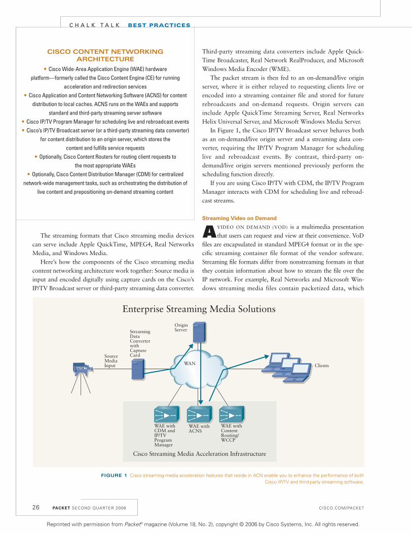
In Figure 1, the Cisco IP/TV Broadcast server behaves bothas an on-demand/live origin server and a streaming data con-verter, requiring the IP/TV Program Manager for schedulinglive and rebroadcast events. By contrast, third-party on-demand/live origin servers mentioned previously perform thescheduling function directly.
If you are using Cisco IP/TV with CDM, the IP/TV ProgramManager interacts with CDM for scheduling live and rebroad-cast streams.
Streaming Video on Demand
AVIDEO ON DEMAND (VOD) is a multimedia presentationthat users can request and view at their convenience. VoD
files are encapsulated in standard MPEG4 format or in the spe-cific streaming container file format of the vendor software.Streaming file formats differ from nonstreaming formats in thatthey contain information about how to stream the file over the IP network. For example, Real Networks and Microsoft Win-dows streaming media files contain packetized data, which
26
FIGURE 1 Cisco streaming-media acceleration features that reside in ACN enable you to enhance the performance of bothCisco IP/TV and third-party streaming software.
C H A L K T A L K BEST PRACTICES
CISCO CONTENT NETWORKING ARCHITECTURE
• Cisco Wide-Area Application Engine (WAE) hardware platform—formerly called the Cisco Content Engine (CE) for running
acceleration and redirection services• Cisco Application and Content Networking Software (ACNS) for content
distribution to local caches. ACNS runs on the WAEs and supports standard and third-party streaming server software
• Cisco IP/TV Program Manager for scheduling live and rebroadcast events• Cisco’s IP/TV Broadcast server (or a third-party streaming data converter)
for content distribution to an origin server, which stores the content and fulfills service requests
• Optionally, Cisco Content Routers for routing client requests to the most appropriate WAEs
• Optionally, Cisco Content Distribution Manager (CDM) for centralized network-wide management tasks, such as orchestrating the distribution of
live content and prepositioning on-demand streaming content
Enterprise Streaming Media Solutions
OriginServerStreaming
DataConverter withCapture CardSource
MediaInput WAN Clients
WAE withCDM andIP/TVProgramManager
WAE withACNS
WAE withContentRouting/WCCP
Cisco Streaming Media Acceleration Infrastructure
Reprinted with permission from Packet® magazine (Volume 18, No. 2), copyright © 2006 by Cisco Systems, Inc. All rights reserved.

CISCO.COM/PACKET
interleaves the audio and video tracks together so that they aresynchronized when the client downloads the stream of packets.Alternatively, MPEG4 and Apple QuickTime files contain sepa-rate hint tracks to tell the server how to synchronously packe-tize the data during real-time delivery.
Cisco WAEs support VoD streaming individually or as a partof an ACNS solution that you administer with a CDM. You canconfigure your individual WAEs with conventional caching tolocally deliver Windows and Real media files to requestingclients. The WAEs can cache this content from internal serversor from anonymous servers on the Internet. As a completeACNS solution, you can preposition Real Networks, MicrosoftWindows, MPEG4, and Apple QuickTime files to WAEsthroughout your network using Cisco CDM. Prepositioninginvolves distributing VoDs to WAEs throughout your network,prior to client requests, using distribution trees. You create thetrees using CDM and ACNS; ACNS software supports bothunicast and multicast VoD file distribution. The benefit ofprepositioning is that you can distribute corporate streamingmedia content after hours, when branch office bandwidth uti-lization is lowest.
Routing Client Requests
CLIENTS ARE REDIRECTED to the appropriate local CiscoWAE appliance automatically in one of three ways: by the
Web Cache Communication Protocol (WCCP) running in thelocal router, by a proxy running on the client device, or by aCisco WAE functioning in “content router” mode at headquar-ters and supporting subdomains for redirection.
For its part, WCCP optimizes content delivery betweenclients and WAEs by transparently redirecting client requeststo appropriate WAEs. WCCP does not inspect the URL orHTTP request to classify traffic for redirection. Instead, aWCCP-enabled router inspects packets on incoming or outgoing
interfaces and matches them against service groups that youconfigure for WCCP inspection. WCCP defines service groupsby port numbers.
WCCP version 2 is required for streaming media requestredirection. For example, WCCPv2 currently supports redirec-tion of standard RTSP, MMS-over-UDP, MMS-over-TCP, andMicrosoft’s implementation of RTSP over UDP. It also supportsmultiple redundant routers, improved security, Layer 2 redirec-tion, and redirection of applications other than HTTP overTCP port 80.
As an alternative to WCCP, you can also configure Ciscocontent switches to redirect client requests to your WAEs. Theadvantage of content switch redirection is that you can config-ure the switch to classify traffic by criteria such as URLs, filenames, and extensions. Another option is to manually configurethe Internet connection settings of each workstation in your net-work to point to the WAE in closest proximity to the particularclient (for example, the one located in the same branch office asthe client). If you are using CDM administration, the complexityof this manual approach can be offset by using dynamic ProxyAuto-Configuration (PAC). Dynamic PAC uses coverage zonesto determine the best-suited WAE for client requests and dynam-ically adjusts a client’s proxy settings with the WAE URL or IPaddress.
A coverage zone is similar to a static route, in that it con-tains the association between a client subnet and the IP addressof the WAE that serves that subnet. As a result, you must createa coverage zone for every subnet in your network that usesyour streaming content. Also available in a CDM-administered
Live and Rebroadcast Stream SplittingWAE
WAE
Single LiveRTP Unicastor MulticastStream
StreamingOriginServer
Multiple Live RTPUnicast Streams or aSingle Multicast Stream
SILVANO DA ROS is a network consultant and a Cisco Press author.
Previously a systems engineer at Cisco Systems, he worked with
enterprise organizations on emerging network solutions.
FIGURE 2 Live splitting conserves bandwidth and network resources by reducing the number of duplicate streams on the network.
Continued on page 81
PACKET SECOND QUARTER 2006 27
Reprinted with permission from Packet® magazine (Volume 18, No. 2), copyright © 2006 by Cisco Systems, Inc. All rights reserved.
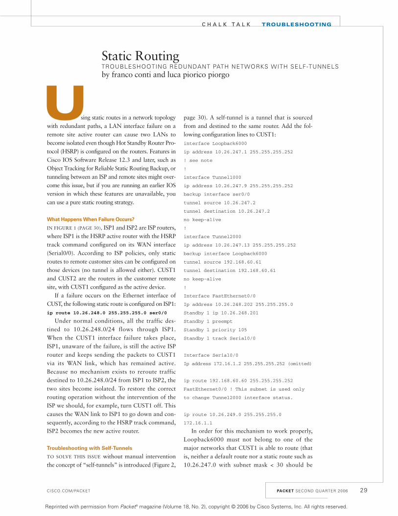
sing static routes in a network topologywith redundant paths, a LAN interface failure on aremote site active router can cause two LANs tobecome isolated even though Hot Standby Router Pro-tocol (HSRP) is configured on the routers. Features inCisco IOS Software Release 12.3 and later, such asObject Tracking for Reliable Static Routing Backup, ortunneling between an ISP and remote sites might over-come this issue, but if you are running an earlier IOSversion in which these features are unavailable, youcan use a pure static routing strategy.
What Happens When Failure Occurs?
IN FIGURE 1 (PAGE 30), ISP1 and ISP2 are ISP routers,where ISP1 is the HSRP active router with the HSRPtrack command configured on its WAN interface(Serial0/0). According to ISP policies, only staticroutes to remote customer sites can be configured onthose devices (no tunnel is allowed either). CUST1and CUST2 are the routers in the customer remotesite, with CUST1 configured as the active device.
If a failure occurs on the Ethernet interface ofCUST, the following static route is configured on ISP1:ip route 10.26.248.0 255.255.255.0 ser0/0
Under normal conditions, all the traffic des-tined to 10.26.248.0/24 flows through ISP1.When the CUST1 interface failure takes place,ISP1, unaware of the failure, is still the active ISProuter and keeps sending the packets to CUST1via its WAN link, which has remained active.Because no mechanism exists to reroute trafficdestined to 10.26.248.0/24 from ISP1 to ISP2, thetwo sites become isolated. To restore the correctrouting operation without the intervention of theISP we should, for example, turn CUST1 off. Thiscauses the WAN link to ISP1 to go down and con-sequently, according to the HSRP track command,ISP2 becomes the new active router.
Troubleshooting with Self-Tunnels
TO SOLVE THIS ISSUE without manual interventionthe concept of “self-tunnels” is introduced (Figure 2,
page 30). A self-tunnel is a tunnel that is sourcedfrom and destined to the same router. Add the fol-lowing configuration lines to CUST1:interface Loopback6000
ip address 10.26.247.1 255.255.255.252
! see note
!
interface Tunnel1000
ip address 10.26.247.9 255.255.255.252
backup interface ser0/0
tunnel source 10.26.247.2
tunnel destination 10.26.247.2
no keep-alive
!
interface Tunnel2000
ip address 10.26.247.13 255.255.255.252
backup interface Loopback6000
tunnel source 192.168.60.61
tunnel destination 192.168.60.61
no keep-alive
!
Interface FastEthernet0/0
Ip address 10.26.248.202 255.255.255.0
Standby 1 ip 10.26.248.201
Standby 1 preempt
Standby 1 priority 105
Standby 1 track Serial0/0
Interface Serial0/0
Ip address 172.16.1.2 255.255.255.252 (omitted)
ip route 192.168.60.60 255.255.255.252
FastEthernet0/0 ! This subnet is used only
to change Tunnel2000 interface status.
ip route 10.26.249.0 255.255.255.0
172.16.1.1
In order for this mechanism to work properly,Loopback6000 must not belong to one of themajor networks that CUST1 is able to route (thatis, neither a default route nor a static route such as10.26.247.0 with subnet mask < 30 should be
CISCO.COM/PACKET PACKET SECOND QUARTER 2006 29
C H A L K T A L K TROUBLESHOOTING
Static RoutingTROUBLESHOOTING REDUNDANT PATH NETWORKS WITH SELF-TUNNELS by franco conti and luca piorico piorgo
U
Reprinted with permission from Packet® magazine (Volume 18, No. 2), copyright © 2006 by Cisco Systems, Inc. All rights reserved.

PACKET SECOND QUARTER 2006 CISCO.COM/PACKET
C H A L K T A L K TROUBLESHOOTING
present. For example, if the route 10.26.0.0/16 is present in therouting table, Tunnel1000 will always be active, preventing the mechanism from working).
Under normal circumstances, Tunnel2000 is active when the static route to 192.168.60.60/30 is present in the routingtable (that is true provided that Fa0/0 is active), and the backupinterface command of T2000 causes Loopback6000 to remaindown. With Loopback6000 down, Tunnel1000 is also down(because the loopback is both the source and the destination of thetunnel) and Serial0/0 isactive (because it is thebackup interface of Tunnel1000).
In the case of aFastEthernet0/0 failurethe static route is with-drawn from the routingtable and T2000 goesdown, causing Loop-back6000 to become
active. But T1000 also becomes active,and finally, thanks to the backup inter-
face command, Ser0/0 goes down.After implementing this mechanism, the serial interface of
ISP1 also goes down, triggering the HSRP status change (active> standby) by means of the track command configured on thatserial. Therefore, the inbound traffic is forwarded throughISP2, which has finally become active.
This is a basic scenario. In a more complex environment,you might need to implement further networking strategiesalong with self-tunnels. For example, you can use recursivelookup in a network topology using a dynamic protocol underCUST1-2 to prevent a similar issue. P
FRANCO CONTI AND LUCA PIORICO PIORGO, both network
engineers for Tele Sistemi Ferroviari in Rome, Italy, have more
than ten years experience in the industry. They can be reached at
[email protected] and [email protected], respectively.
30
FIGURE 2 The self-tunnel is sourced from and destined to the same router.
10.26.249.0/24
10.26.248.0/24
202 203
202 203
.1
.2172.
16.1
.0/3
0
S.0/0S.0/0
S.0/0S.0/0
FIGURE 1 Customer sites become isolated from each other when the CUST1Ethernet interface fails.
T6000
T1000 T2000
Reprinted with permission from Packet® magazine (Volume 18, No. 2), copyright © 2006 by Cisco Systems, Inc. All rights reserved.

nterprise data centers are complexenvironments that host mission-critical servers,databases, and data storage devices. As such, it goeswithout saying that data center designs must addresshigh availability, scalability, and redundancy.
There are several distinct approaches and method-ologies to building a data center with these traits.Being successful requires that you keep applicationbehavior in mind during the planning and designphase. This means considering issues such as applica-tion flows, scalability, redundancy, load balancing,migration, management, and security. For example, ifyou are consolidating multiple data centers into one,take inventory of the number ofservers and other devices you aremigrating so you can appropriatelysize the new facility to accommo-date the consolidated resources. Arecommended approach is to buildthe new facility with rack space thataccommodates scaling by five- totenfold to allow for growth.
It’s also important to understandthe various application flows to besupported—which devices each application trav-erses and which protocols they use—so that eachapplication can be supported properly. For example,if an application receives 10,000 requests per sec-ond, it cannot be supported successfully from a sin-gle server and will thus require load balancing acrossmultiple servers.
Finally, building a data center in a modular fash-ion that allows physical devices to provide virtual-ized services across a number of business units andapplications is integral to building scalability intoyour data center design.
Why Consolidate Data Centers?
KEY BUSINESS DRIVERS BEHIND data center consoli-dation include improved cost control, increasedoperational efficiency, and more effective resourceutilization. Following are some of the primary
motivations behind consolidated data centers:• Network infrastructure cost savings—The
reduction in the number of network services andenterprise devices such as switches or routers yielddirect cost savings. For example, a consolidated datacenter design enables the enterprise to virtually seg-ment a server load-balancing device to service multi-ple applications or business units instead ofoperating a separate pair of load-balanced servers forevery business unit. Similarly, a firewall services mod-ule deployed in a virtualized fashion in an aggrega-tion switch allows the one physical firewall tofunction as multiple logical firewall instances.
• Standardization and central-ization of resources—Often in datacenter consolidation, the numberof distributed server farms isreduced, and servers are relocatedto existing or new facilities. Thesenew consolidated data centers areinterconnected, and the opera-tional, support, and design bestpractices standardized. Likewise,application, server, and storage
resources are centralized. This standardization andcentralization yields much lower total cost of own-ership (TCO) than before the consolidation.
In a different take on centralization, if certainfunctions are collapsed into services modules in arouting/switching device, such as the Cisco Catalyst6500 Series Switch, the management of those sepa-rate functions is consolidated, as well. For example,if a pair of redundant Catalyst 6500 switches is con-figured with a Content Switching Module (CSM) forload balancing, an SSL Services Module (SSLM),and a Firewall Services Module (FWSM), the man-agement of these devices can be centralized to someextent. The FWSM does require separate manage-ment using the Cisco VPN/Security ManagementSolution (CiscoWorks VMS). However, the status ofall modules can be polled from the Catalyst 6500
CISCO.COM/PACKET PACKET SECOND QUARTER 2006 31
Data Center Consolidation TipsMIGRATING TOWARD CONSOLIDATION? HERE ARE SOME CONSIDERATIONS AND DESIGN EXAMPLES. by zeeshan naseh
THE MOST common
trend affecting
data centers worldwide
today is consolidation.
C H A L K T A L K DESIGN STRATEGY
AC
HIL
LI
BIG
LIA
RD
I P
HO
TO
GR
AP
HY
E
Continued on page 33
Reprinted with permission from Packet® magazine (Volume 18, No. 2), copyright © 2006 by Cisco Systems, Inc. All rights reserved.
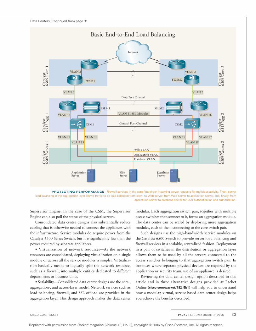
CISCO.COM/PACKET
Supervisor Engine. In the case of the CSM, the SupervisorEngine can also poll the status of the physical servers.
Consolidated data center designs also substantially reducecabling that is otherwise needed to connect the appliances withthe infrastructure. Service modules do require power from theCatalyst 6500 Series Switch, but it is significantly less than thepower required by separate appliances.
• Virtualization of network resources—As the networkresources are consolidated, deploying virtualization on a singlemodule or across all the service modules is simpler. Virtualiza-tion basically means to logically split the network resource,such as a firewall, into multiple entities dedicated to differentdepartments or business units.
• Scalability—Consolidated data center designs use the core-,aggregation-, and access-layer model. Network services such asload balancing, firewall, and SSL offload are provided in theaggregation layer. This design approach makes the data center
modular. Each aggregation switch pair, together with multipleaccess switches that connect to it, forms an aggregation module.The data center can be scaled by deploying more aggregationmodules, each of them connecting to the core switch pair.
Such designs use the high-bandwidth service modules onthe Catalyst 6500 Switch to provide server load balancing andfirewall services in a scalable, centralized fashion. Deploymentin a pair of switches in the distribution or aggregation layerallows them to be used by all the servers connected to theaccess switches belonging to that aggregation switch pair. Ininstances where separate physical devices are required by theapplication or security team, use of an appliance is desired.
Reviewing the data center design option described in thisarticle and in three alternative designs provided at PacketOnline (cisco.com/packet/182_5b1) will help you to understandhow a modular, virtual, service-based data center design helpsyou achieve the benefits described.
PACKET SECOND QUARTER 2006 33
Basic End-to-End Load Balancing
VLAN 2
VLAN 3
VLAN 19VLAN 19 VLAN 17VLAN 17
VLAN 18VLAN 18
VLAN 2
VLAN 3
VLAN 16VLAN 16
Cat
alys
t65
09 C
ore
1
Cat
alys
t65
09 C
ore
2
Internet
Cat
alys
t65
13 A
gg 1
Cat
alys
t65
13 A
gg 2
Cat
alys
t65
09 A
cces
s 1
Cat
alys
t65
09 A
cces
s 2
Web VLAN
Application VLAN
Database VLAN
CSM2CSM1
SSLM2SSLM1
VLAN 11 SSL Modules
Data Port Channel
Control Port Channel
ApplicationServer
WebServer
DatabaseServer
FWSM1 FWSM2
PROTECTING PERFORMANCE Firewall services in the core first check incoming server requests for malicious activity. Then, server load balancing in the aggregation layer allows traffic to be load balanced from client to Web server, from Web server to application server, and, finally, from
application server to database server for user authentication and authorization.
Data Centers, Continued from page 31
Reprinted with permission from Packet® magazine (Volume 18, No. 2), copyright © 2006 by Cisco Systems, Inc. All rights reserved.

PACKET SECOND QUARTER 2006 CISCO.COM/PACKET
C H A L K T A L K DESIGN STRATEGY
Sample Data Center Design: End-to-End Load Balancing
BASIC END-TO-END LOAD BALANCING IS a fairly commondesign implementation where the FWSMs or appliance-
based firewalls reside in the core network layer, and the CSMsand SSLMs are implemented in the aggregation layer. The figureon page 33 displays the logical topology, not the physical con-nectivity representation.
The strategy behind this design is to enable load balancingalong the entire traffic flow. In the case of a client requestdesigned for Web servers, the first session comes in from theInternet (HTTP port 80) and traverses the firewall module orappliance, running in Layer 3 mode, to make sure that therequest is not malicious. The FWSM (or appliance) constitutesthe security perimeter between the untrusted Internet and thetrusted data center, and the aggregation and access layers areconsidered trusted zones.
From there, the request is forwarded to the Catalyst 6500aggregation switch pair, destined for a virtual IP (VIP) addressthat resides on the CSM, which is deployed in routed mode.Using virtual LANs (VLANs), the CSM can load balance con-nections to all back-end resources. When the request reachesthe virtual server on the CSM, the CSM load balances it acrossthe appropriate Web servers, which can initiate another sessionto the application servers, if necessary. In this design, trafficfrom the Web server to the application server will also be loadbalanced. The application server now needs to communicatewith the database server to obtain user authorizations and cre-dentials, and the CSM load balances those requests, as well.
The key importance of this design is that it enables load bal-ancing in all directions. The IP connectivity in this design can besummarized as follows: • The Multilayer Switch Feature Card (MSFC) router services
module on the Catalyst 6509-Core-1 and Catalyst 6509-Core-2 connects to the Internet. This link is direct orthrough edge routers.
• Toward the inside, the MSFC connects to the FWSM overVLAN 2.
• The FWSM connects to the MSFC in the aggregationswitches over VLAN 3.
• The aggregation MSFC connects to the CSM on VLAN 16.• All load-balanced server VLANs (17 to 19) exist on the
CSM.• VLAN 11 is the SSLM VLAN on the CSM.• Connectivity between aggregation and access is at Layer 2
(switched).
High Availability Best Practice
FOR HIGH AVAILABILITY, all components are deployed in aredundant manner: two core switches, two firewalls, two
aggregation switches, two CSMs, and redundant paths to the
aggregation switches. Cisco Hot Standby Routing Protocol(HSRP) support in the Catalyst 6500 Series Switch enables state-ful failover of routing/switching from one switch to the other. Inaddition, the CSM and FWSM are stateful devices, so a shiftfrom one switch to another retains all the CSM and FWSM stateinformation for seamless failover. In the figure, the CSM’sdefault gateway is the HSRP group IP on the aggregation-layerCatalyst 6513 MSFC on VLAN 16.
Design 1 Configuration
FOLLOWING IS THE PARTIAL CSM configuration templateused for this design:
!
module ContentSwitchingModule 3
vlan 16 client
ip address 10.16.1.12 255.255.255.0
gateway 10.16.1.1
alias 10.16.1.11 255.255.255.0
!
vlan 11 server
ip address 10.11.1.2 255.255.255.0
alias 10.11.1.1 255.255.255.0
!
vlan 17 server
ip address 10.17.1.2 255.255.255.0
alias 10.17.1.1 255.255.255.0
!
vlan 18 server
ip address 10.18.1.2 255.255.255.0
alias 10.18.1.1 255.255.255.0
!
vlan 19 server
ip address 10.19.1.2 255.255.255.0
alias 10.19.1.1 255.255.255.0
!
!
serverfarm ROUTE
no nat server
no nat client
predictor forward
!
vserver ROUTE
virtual 0.0.0.0 0.0.0.0 any
serverfarm ROUTE
persistent rebalance
inservice
!
The following configuration example shows a partial config-uration from the MSFC in the aggregation switch:
34
Reprinted with permission from Packet® magazine (Volume 18, No. 2), copyright © 2006 by Cisco Systems, Inc. All rights reserved.
CISCO.COM/PACKET
MSFC SVI
!
interface Vlan16
ip address 10.16.1.2 255.255.255.0
standby 16 ip 10.16.1.1
standby 16 priority 150
Other Considerations
IN THIS BASIC DESIGN, the security perimeter created by thefirewall in the core protects the Internet-to-Web server edge
only; this security is not possible between the Web, application,and database tiers. In the aggregation layer, however, some secu-rity using VLAN tags on the CSM to segregate traffic is possible.
Also, some extra configuration apart from the load-balanc-ing configurations is needed on the CSM for direct access toservers and non-load-balanced, server-initiated sessions.Because the MSFC is directly connected to the CSM on VLAN16, a capability called route health injection (RHI) can beused. RHI allows the CSM to advertise the availability of aVIP address throughout the network. Multiple CSM deviceswith identical VIP addresses and services can exist throughoutthe network. This allows one CSM to override the server load-
balancing services of others if those services on the otherdevices should become unavailable.
In this design, both application traffic and management traf-fic are load balanced. If there is a crash in the inline CSM, man-agement access to the physical servers is thus cut off. The samecondition applies to any server-initiated flows: syslog messages,upgrade downloads, or Internet-launched software patches willall traverse the load balancer. Ideally, downloads and manage-ment traffic should bypass the load balancer. Otherwise, if youwant to send traffic to a specific server to determine manage-ment information, load balancing might send your request tothe wrong server.
The three additional data center design options available atcisco.com/packet/182_5b1 describe how to build upon the basicconfiguration in this article to layer on tiered security and toprevent management traffic from being load balanced. P
ZEESHAN NASEH, CCIE NO. 6838, is a technical leader in Cisco’s
Advanced Technologies Services Group and author of the data
center book Designing Content Switching Solutions (ISBN
1-58705213x). He can be reached at [email protected].
PACKET SECOND QUARTER 2006 35
Reprinted with permission from Packet® magazine (Volume 18, No. 2), copyright © 2006 by Cisco Systems, Inc. All rights reserved.

PACKET SECOND QUARTER 2006 CISCO.COM/PACKET36
AR
TIS
T N
AM
E
PEOPLEPEOPLER E A C H I N G
New Unified Communications product portfolio changes everything
Reprinted with permission from Packet® magazine (Volume 18, No. 2), copyright © 2006 by Cisco Systems, Inc. All rights reserved.

CISCO.COM/PACKET
C O V E R S T O R Y
Communications technologyis poised on the brink of a transition as significant asthe one from analog todigital, and from digital to IP. “The first hurdle inunified communications was
tuning the network to handle performance-sensitiveapplications such as voice and video,” says RickMoran, vice president for IP communications in theProduct and Technology Marketing Organizationat Cisco. “Cisco Unified Communications heraldsthe next phase, which is to improve the way thatpeople work with applications and with other peopleusing presence services and open standards.”
Introduced in March, Cisco Unified Communi-cations is an integrated, comprehensive businesscommunications system that includes more than30 new products, enhanced management andadministration, and simplified pricing and serviceofferings. Major enhancements include: • Presence and preference information that helpsemployees reach the right person, the first time, onthe available device that will provide the richestcommunications experience.• Greater openness through Session Initiation Protocol (SIP) support, enabling developers tointroduce new SIP-compliant endpoints and applications. • More options for reaching mobile employees,including dual-mode phone support and MobileConnect for single-number reach.
Overcoming Complexity
Why the change, and why now? “The myriadcommunications technologies that have evolved to support a global, mobile workforce have introduced too much complexity,” says Vickie McGovern, director of marketing for unifiedcommunications in Cisco’s Product and Technol-ogy Marketing Organization. The average businessperson uses more than six communications devicesand more than four communications applications,such as e-mail and various instant messaging (IM)clients, according to a September 2005 survey bySage Research. And Gartner predicts that by 2007,more than 66 percent of the overall workforce will use mobile or wireless computing devices. “Ifyou want to reach a co-worker right away, how doyou know which device to use?” McGovern asks.
In fact, the tedious process of trying to reachco-workers and partners on one device afteranother—a concept that McGovern calls “humanmiddleware”—is a glaring omission in today’sbusiness process integration (BPI) efforts.“Neglecting to integrate communications intobusiness processes delays decision-making, whichnegatively affects the top and bottom lines,” shesays. Inefficient communications hamper strategicinitiatives such as lean/just-in-time manufacturing,supply-chain optimization, customer relationshipmanagement (CRM), and Six Sigma. It can havedisastrous results in perishable goods industries.And it can impede the development of next-gener-ation contact center environments that depend on the ability to quickly escalate customerinquiries, route them to the right expert across the distributed contact center, and resolve themquickly using the optimum mix of media.
The goal of Cisco Unified Communications is to use the power of the network to transform com-munications into an asset rather than a liability tobusiness processes. “Cisco Unified Communicationsintegrates communications with business processesso that organizations can be more responsive to customer needs and enhance business and employeeproductivity,” says Don Proctor, senior vice presi-dent of the Cisco Voice Technology Group. “It candirectly improve the top and bottom lines.”
PACKET SECOND QUARTER 2006 37
GE
TT
YIM
AG
ES
about the way businesses communicate.b y R H O N D A R A I D E R
Reprinted with permission from Packet® magazine (Volume 18, No. 2), copyright © 2006 by Cisco Systems, Inc. All rights reserved.

PACKET SECOND QUARTER 2006
Top-Line Impact of Unified Communications
Say a customer calls to place a large order and theaccount executive is away from her desk. In most businesses today, the sale is delayed until theaccount rep checks voice mail and is able to connect
with the customer—who by this time might also be away fromthe phone.
Cisco Unified Communications provides new capabilitiesthat can speed up revenue realization. If the account rep has adual-mode phone, he or she can receive the call via GSM whenout of range of the office’s 802.11 network, making it unnec-essary for callers to be aware of and dial two different num-bers (see sidebar, “IP Phones: What’s New,” page 39). Or theaccount rep does have separate cel-lular and office phones, he or shecan use the Cisco Mobile Connectservice, enabled by Cisco UnifiedMobility Manager, to either havemultiple phones ring at the sametime or have all calls routed to aparticular device. The Cisco MobileConnect service even enables therep to transfer a call in progress onher cell phone to her office phonewhen she arrives at the office, with-out interrupting the call.
Now suppose the customer onthat call requests a product modifi-cation to clinch the sale. Cisco Uni-fied Communications can help
facilitate an ad-hoc meeting. The repwalks into an office and launches anew desktop application, Cisco Unified Personal Communicator,which shows presence and prefer-ence information that the Cisco Uni-fied Presence Server has aggregatedfrom other elements of the CiscoUnified Communications system (seesidebar, “Cisco Unified PersonalCommunicator”).
The rep quickly identifies prod-uct team members who are cur-rently available by phone, andsimply drags their names into awindow to launch an immediatecollaborative session on Cisco Uni-
fied MeetingPlace Express, combining voice and video confer-encing and Web collaboration. (Employees using the newCisco Unified IP Phone 7985, a personal desktop video phone,can escalate from a voice-only session to voice and video atany time during the call.) They view the agreement and workout any details in real time, enabling the account rep to closethe sale in the shortest possible time.
Presence and Presence
Cisco Unified Communications uses the pervasive reach of anintelligent network so that people reach people, not just unat-tended communications devices. Cisco Unified Presence Serveraggregates and publishes presence information from all SIP-enabled devices and applications in the network, including CiscoUnified CallManager, Cisco Unity Voice Mail, Cisco UnifiedMeetingPlace, and new models of Cisco Unified IP phones.
38
C O V E R S T O R Y
UNIFIED COMMUNICATIONS Actual benefits exceed expectedbenefits for an increasingly mobile workforce.
Available for both Microsoft Windows XP and Macintosh OS X operating systems, Cisco Unified Personal Communicator integrates directories, presenceinformation, and Cisco Unified MeetingPlace into a single Web-based interface, helping employees communicate more effectively and be more productive. To communicate with another person on the network, a user simply
drags that person’s name into a window, andthe system reaches out according to thepresence and preference information availableon the network—dialing the appropriatephone, sending an instant message, or callingthe Cisco Unity voice-mail box if no other options are available.
Cisco Unified Personal Communicator
Benefits of Unified Communications
Non-Users Expected Benefits Users/Actual Benefits
Easier to PrioritizeImportant Communications
Increased Collaboration
Simplified Communications
Faster Communications
Enhanced Productivity82%
64%
79%62%
66%43%
63%43%
58%
21%
0% 20% 40% 60% 80% 100%
Source: Sage Research
Percentage of Respondents
Ben
efit
s
CISCO.COM/PACKET
Reprinted with permission from Packet® magazine (Volume 18, No. 2), copyright © 2006 by Cisco Systems, Inc. All rights reserved.

CISCO.COM/PACKET
Presence information appears on SIP-enabled devices andapplications, including Cisco Unified IP phones and CiscoUnified Personal Communicator. An employee who views adirectory or call log on either interface sees beside eachentry whether the caller is on the phone, off the phone, orhas left a message such as “Back in five minutes,” or “Callmy cell phone.”
“Most people still think of presence as, ‘Are you there?’”says Joe Burton, director of engineering for the Cisco VoiceTechnology Group. “Cisco extends the concept by also trackingthe users’ device capabilities, enabling the richest communica-tions experience possible.” For example, by communicatingwith the Cisco Unified CallManager, Cisco Unified PresenceServer knows whether an individual in a Cisco Unified Meet-ingPlace conference also has video capabilities.
Users can supplement or override presence informationby entering preferences in Cisco Unified Personal Communi-cator—for example, that they prefer e-mail to voice mail, or do not want to be disturbed under any circumstances until 10 a.m.
“Preference features in CiscoUnified Personal Communicatorenable employees to opt in or optout of a particular communicationsmode,” says McGovern. “The con-cept is sometimes called, ‘Find me,follow me, hide me.’”
SIP for Presence and Openness
Cisco Unified Communicationstakes advantage of standards suchas SIP, SIMPLE, SOAP, and Ajaxto enable interoperability amongdifferent types of communicationsdevices—voice, video, IM, cellu-lar—from different vendors.
An IETF standard, SIP defineshow disparate devices set up a ses-sion, share real-time mediastreams, and terminate the ses-sion. SIP makes Cisco UnifiedCommunications an open plat-form. People who use SIP-compli-ant voice, video, or IM clientsfrom different vendors can com-municate, and developers canfreely add new capabilities. “Theidea of SIP is to connect people topeople, shielding those peoplefrom the details of how device is
connected to device,” says McGovern. In the future, forexample, an IM message sent to a person who only has a cellphone available might be translated to speech for delivery.
Cisco has incorporated line-side SIP support into CiscoUnified CallManager 5.0, Cisco Unified CallManagerExpress 3.4, Cisco Unified Survivable Remote SiteTelephony 3.4, and certain Cisco Unified IP phones
and video endpoints. SIP is implemented natively in Cisco UnifiedCallManager as a base protocol. “Companies that use Cisco Uni-fied CallManager can decide whether to use SIP alone, SCCPalone, or both,” says Hadden-Boyd. Today SCCP has a richerfeature set, but SIP will surpass it as vendors take advantage ofthe standard to add new functions. Hadden-Boyd expects thatmany customers will begin with SCCP and then gradually addSIP as they deploy SIP-enabled voice and video endpoints andapplications, some with features not even imagined today.
Hadden-Boyd notes that Cisco Unified Communicationsincludes SIP support not only on Cisco Unified CallManager,but also Cisco Unified CallManager Express and Cisco
PACKET SECOND QUARTER 2006 39CISCO.COM/PACKET PACKET SECOND QUARTER 2006 39
Enhanced Mobility: Cisco Unified Communications supports dual-mode phones fromNokia, which combine the functionality of a wireless IP phone and a cellular phone.They connect via IEEE 802.11b/g when the signal is available and otherwise via GSM,enabling single business-number reach. Another boon for mobility, the Mobile Connectservice enables employees to transfer calls between their cell phones and Cisco IPphones, or vice versa. “Recently my cell phone rang when I was at the Munich air-port,” says Brian Dal Bello, director of Cisco Unified CallManager product marketing.“The call was from an account executive in the US who had dialed my Dallas office. I was able to resolve her issue immediately instead of waiting until I heard a voice mailmany hours later.” Had the call continued after Dal Bello arrived at a Cisco office, hecould have transferred the call to any Cisco IP phone, avoiding unnecessary per-minute charges from the cellular service provider.
Gigabit Ethernet Phones: Several new Cisco Unified IP phones can connect to computers with Gigabit Ethernet connections: the Cisco Unified IP Phone 7961G-GE(gray-scale with six buttons), 7941G-GE (gray-scale with four buttons), and 7971G-GE(color with touch-sensitive display).
Enhanced SIP Support: When used with Cisco Unified CallMan-ager 5.0, Cisco Unified IP Phones 7971G, 7970G, 7961G, 7941G, and7911G support enhanced SIP services, such as presence.
Unicode Support: Cisco Unified CallManager 5.0 now offers Unicode support, enabling users in Japan, Korea, and China to seetheir own alphabets on the display of Cisco Unified IP phones. Support for Arabic is planned.
IP Phones: What’s New
Reprinted with permission from Packet® magazine (Volume 18, No. 2), copyright © 2006 by Cisco Systems, Inc. All rights reserved.

Survivable Remote Site Telephony (SRST). “The advantage ofimplementing SIP in SRST is that the call-processing systemworks the same way even if a WAN link between a centralizedCisco Unified CallManager server and a remote office goesdown,” she says. “Users can continue to use the same devicesand applications.”
Federated Presence
SIP support in Cisco Unified Presence Server also enables itto share presence information with other SIP-compliant pres-ence servers, enabling a “federated presence.” “If onedepartment in a company has deployed a SIP-compliantpresence server such as Microsoft Live CommunicationsServer (LCS) or Lotus SameTime, and another departmentdeploys Cisco Unified Presence Server, employees in alldepartments can use their respective client devices and appli-cations to view presence information for all employees,” saysBurton.
The Network Knows
Multiple vendors are introducing unified commu-nications clients, some approaching it from thedesktop layer, others from the application layer.Only Cisco has approached presence from the
network layer. One advantage is that the network is privy topresence information not only from the call-processing com-ponent (Cisco Unified CallManager) but also the applica-tions layer (Cisco Unity Voice Mail and Cisco UnifiedMeetingPlace), creating a more complete picture of avail-ability.
“Network-based presence information is also more accuratethan calendar-based presence information because the calen-dar’s owner might not have attended a scheduled meeting, forexample, or double-booked just in case one canceled,” addsMcGovern.
Another advantage of the network-based approach is thatthe Cisco Unified Communications solution inherits all the secu-rity built into the IP network, avoiding the need for securityinvestments specific to the voice system.
Holistic Management
Cisco Unified Communications improvesIT staff productivity with two new tools forintegrated network and system manage-ment. “The more types of devices andapplications that we add to the IP network,the more important it is to have a holisticmanagement system that addresses boththe applications the underlying infrastruc-ture of switches and routers,” says Moran.
Cisco Unified Operations Manager pro-vides a visual, dashboard-like interface for IT to monitor thereal-time operational status of all components in the Cisco Uni-fied Communications system, including Cisco Unified CallMan-ager, Cisco Unified IP phones, Cisco Unity Messaging, CiscoUnified MeetingPlace, and underlying Cisco routers andswitches. It shows the real-time relationship among solutioncomponents, such as which Cisco Unified CallManager server isassociated with a particular set of IP phones.
“I can find out the status of any phone in the company in abouta minute simply by entering its extension,” says Mike DeDecker,network administrator for Warner Pacific Insurance Services, whichuses the Cisco Unified Communications management software.
The new Cisco Unified Service Monitor provides real-timereporting of voice quality anywhere in the network. It capturesand analyzes statistics about the voice session and reports themas a Mean Opinion Score (MOS) every 60 seconds.
Taking Fuller Advantage of the Network
“The guiding principle in Cisco Unified Communications is totake advantage of the network’s awareness and capabilities formore effective communication and streamlined businessprocesses,” says Hadden-Boyd. “Cisco has already taken theintelligence and security of the network and applied it to the call-processing layer. With Cisco Unified Communications we areusing SIP, SIMPLE, and other standards to extend network intel-ligence and security to the application layer.” P
Cisco is introducing a new appliance model, in which Cisco Unified CallManager comes preloaded on a server. Customers won’t need to touchthe underlying Linux operating system. For organizations that prefer an openoperating system model, Cisco Unified CallManager is still available in a Windows operating system version, providing full visibility into the operatingsystem and the option to customize certain aspects of call processing.
New Appliance Model Option for Cisco Unified CallManager
Further Reading• Cisco Unified Communications system
cisco.com/go/unified
• Cisco Unified Presence Server video
cisco.com/packet/182_6a1
• Podcast with Cisco Distinguished Engineer
Cullen Jennings
cisco.com/packet/182_6a2
CISCO.COM/PACKET
C O V E R S T O R Y
PACKET SECOND QUARTER 200640
Reprinted with permission from Packet® magazine (Volume 18, No. 2), copyright © 2006 by Cisco Systems, Inc. All rights reserved.

PACKET SECOND QUARTER 2006 CISCO.COM/PACKET
F E A T U R E
F O R W A R D T H I N K E R S and early technologyadopters, rejoice. Cisco Lifecycle Services promises to takemuch of the pain out of deploying new advanced technologiessuch as network security or IP communications.
The Cisco Lifecycle Services approach is a framework ofbest practices that outlines the critical activities required todeploy and operate an advanced technology. This detailedmethodology is based on six lifecycle phases—prepare, plan,design, implement, operate, and optimize. Galvanizing thisapproach is Cisco’s strategy to ensure that its customers haveaccess to highly qualified channel partners to see themthrough each phase.
Karl Meulema, Cisco’s vice president of services marketingand channels, is credited with expanding on the industry-rec-ognized concept of incorporating technology deployment andoperations into a lifecycle framework. To give life to thisvision, Meulema developed sound methodologies that can bereproduced and scaled by enabling partners and then collabo-ratively supporting customers.
Packet: How do you define Cisco Lifecycle Services?KM: Lifecycle Services is an accurate description of the
activities that an end customer needs to be successful with Ciscotechnologies. In essence, it’s about accelerating the learningcurve around our technologies. It is not a service offering. Ican’t emphasize that strongly enough. It’s a collection of bestpractices for a given technology, developed through our ownexperience and validated through that of our partners. LifecycleServices is a very specific, documented set of best practices.
Packet: So how does it help Cisco customers?KM: For any technology that a company such as Cisco
42
Life cycle
BEST PRACTICES FORORGANIZATIONS DEPLOYING
ADVANCED TECHNOLOGIES by joanna holmes
T H E N E T W O R K
PH
ILIP
PE
LA
RD
Y
Reprinted with permission from Packet® magazine (Volume 18, No. 2), copyright © 2006 by Cisco Systems, Inc. All rights reserved.

CISCO.COM/PACKET
might introduce, if that technology isrelatively new to the outside world,then there is limited or no experiencein the marketplace to help make itsdeployment successful. As a technol-ogy matures, it commoditizes. Peoplehave taken every conceivable path toa potential end zone. What works andwhat doesn’t work become generalknowledge, and things become nor-malized in the process.
But if you’re a customer juststarting out with a newtechnology and the knowl-edge base isn’t there yet, try-
ing to map your own course to thatend zone can waste a lot of cycles,money, and time.
Packet: And that’s where LifecycleServices comes in?
KM: Exactly. The goal is to short-cut that learning curve by building upour knowledge base very early in theproduct lifecycle, and then document-ing it in a way that we can share itwith others. So rather than expectingour customers and partners to figure itout by themselves, we share ourknowledge of what actually works,through every stage of the network orsolution lifecycle. We impart thisknowledge to our partners in such away that they become an extension ofCisco in supporting the customer.
If customers properly implement themethodologies and descriptions associ-ated with a given lifecycle, we expectthat they will be successful, becausethose methodologies and descriptionshave led to previous successes. I thinkthat’s a key component, the fact thatour foundation is not based on theory,but on proven best practices.
Packet: Will these methodologiesbe available for each new advancedtechnology that Cisco introduces?
KM: Yes. Every time we come outwith a new advanced technology—ora major revision of an advanced tech-
PACKET SECOND QUARTER 2006 43
Reprinted with permission from Packet® magazine (Volume 18, No. 2), copyright © 2006 by Cisco Systems, Inc. All rights reserved.

CISCO.COM/PACKET PACKET SECOND QUARTER 2006 45
nology—we will create lifecycle services to accompany it. AndCisco committed to come out with new advanced technologieslike clockwork, so we’ll continue to have many technologiesthat are not yet mature—and for those technologies, the impor-tance of Lifecycle Services is enormous.
Packet: What about Cisco’s channel partners? What’s theirrole in these activities?
KM: The way we make Lifecycle Services a successful pro-gram for Cisco is through taking these activities and combiningthem with our go-to-market strategy, which is highly channel-driven. Between those two elements, we make sure we under-stand what’s required to make Cisco partners capable andprofitable, and what we need to add to augment the partners’capabilities in terms of our own services portfolio.
We’ve added Lifecycle Services to our Channel Partner Pro-gram as one of the key specialization criteria. So our strat-egy to ensure that our customers have access tocapable, profitable partners is fully aligned withLifecycle Services. And now, the ways inwhich our channel partners make marginand get discounts from us is directly tied totheir demonstrable capabilities in deliver-ing services that address the lifecycle as wedefine it.
Packet: Who actually provides the serv-ices for customers? The partners?
KM: It could be the customers themselves, thepartners, Cisco, or any combination thereof. In myorganization we always say that we’re about accelerating cus-tomer success with our technologies. Lifecycle Services is one ofthe best proof points for accelerating customer success,because—by its definition—we are precisely describing the cus-tomer success that our technology can encompass, regardless ofwho delivers it.
Customers can take on part of these activities them-selves, although, realistically, few of them will. Wevery seldom see Cisco users actively engaging in thepreparing, planning, designing, implementing, oper-
ating, and optimizing stages of theirown networks and network solu-tions. For most customers, it’s diffi-cult to develop and maintain thatskill set as a core competency.
Regardless, the “who” is not soimportant when we talk about serv-ice delivery. What is important isthat between our partners, cus-tomers, and Cisco, we perform allthe prescribed activities in the right
sequence. Only then can we be confident that the solution willdo what it’s supposed to do, when it is supposed to do it.
The value that our customers are looking for is notthat hot new technology—it’s a business return fortheir solution. So while they’re planning their returnon investment, it’s critical that the solution actually
meets expectations.In our experience, the customers who have been most suc-
cessful in realizing strong returns on their investments arethose who budgeted for the appropriate services. Often, wesee buyers trying to contain the overall price of a solution byremoving services from their final bid. The hidden cost of afailed or semi-failed deployment is far greater than the savingson these services, which are so critical for success.
Customers might feel that a solution can be successfulwithout upfront assessments of the network, a com-
prehensive architecture, or ongoing optimizationactivities to ensure that the solution not only
works, but continues evolving as the cus-tomers’ business processes evolve. Theproblem with this approach is that they endup with a solution that doesn’t do whatthey had expected of their investment
throughout its lifecycle. In most of theseinstances, an array of hidden costs far outstrips
the upfront savings on services.Packet: If Lifecycle Services means helping Cisco
users achieve successful deployments for new advanced tech-nologies, what first step should those users take?
KM: That’s an easy one. I’d like our users, when they thinkabout implementing a solution, to think about the full solution,end to end. When they think this way, they include services intheir earliest ideas about what it would take to make their tech-nology deployment successful.
It’s not just about a lot of very high-tech, very innovativeproducts. It’s also about planning for the right services upfrontand having the solution delivered on time, meeting customers’requirements, and meeting the ultimate business needs. P
Prepare
Plan
Design
Implement
Operate
Optimize
Cisco provides Lifecycle Services for Cisco Unified Communications, security,wireless LAN, and routing and switching.
To learn more about Cisco Lifecycle Services, visit cisco.com/go/lifecycle. To learn more about Cisco services in general, visit cisco.com/go/services.
Current Supported Technologies
Reprinted with permission from Packet® magazine (Volume 18, No. 2), copyright © 2006 by Cisco Systems, Inc. All rights reserved.
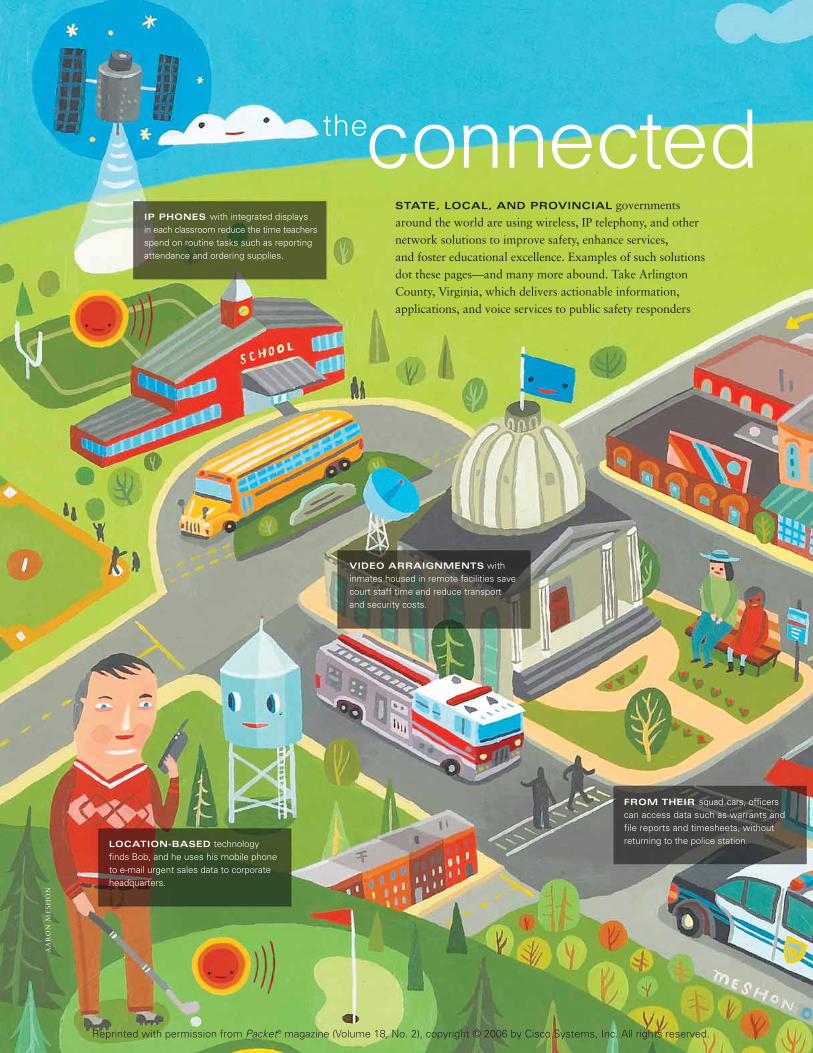
PACKET SECOND QUARTER 200646
AA
RO
N M
ES
HO
N
connected STATE, LOCAL, AND PROVINCIAL governments around the world are using wireless, IP telephony, and other network solutions to improve safety, enhance services, and foster educational excellence. Examples of such solutionsdot these pages—and many more abound. Take ArlingtonCounty, Virginia, which delivers actionable information, applications, and voice services to public safety responders
the
FROM THEIR squad cars, officerscan access data such as warrants andfile reports and timesheets, withoutreturning to the police station.
VIDEO ARRAIGNMENTS withinmates housed in remote facilities savecourt staff time and reduce transport and security costs.
IP PHONES with integrated displays in each classroom reduce the time teachersspend on routine tasks such as reportingattendance and ordering supplies.
LOCATION-BASED technologyfinds Bob, and he uses his mobile phoneto e-mail urgent sales data to corporateheadquarters.
Reprinted with permission from Packet® magazine (Volume 18, No. 2), copyright © 2006 by Cisco Systems, Inc. All rights reserved.

PACKET SECOND QUARTER 2006 47
communityin the field using wireless connectivity, and broadcasts real-time training to staff in ten fire stations. Many of these connected communities save US$200,000+ in telecom costs annually, gain countless hours in productivity, and improve communications across the board. And all are improving their community quality of life. P
Network technologies build and strengthen communities everywhere.
INTERACTIVE, real-time video and video on demand increase staff efficiency and enhance student curricula.
PARKING METERS capture video of illegally parked cars with a timestamp;citizens who receive parking citations can view the video on the Internet.
IPTV technology in helicopters transmits live video footage of major incidents to police stations in the cityand neighboring jurisdictions.
AT A CITY HOTSPOT, buildinginspectors wirelessly submit reports andretrieve forms and data on their laptops,expediting the approval process.
WIRELESS
Hotspots
Reprinted with permission from Packet® magazine (Volume 18, No. 2), copyright © 2006 by Cisco Systems, Inc. All rights reserved.

PACKET SECOND QUARTER 2006 CISCO.COM/PACKET
So many network endpoints;so many internal network components. Somany applications with critical businessdepending on them. The time in which a threatcan damage a network and a business has gonefrom days to seconds. Meanwhile, the amountof vigilance required to keep threats at bay hasincreased exponentially. The advantage, as inany good defense, comes from outsmarting andout-strategizing your opponent. In a technicalgame such as network security, it also comesfrom solid underlying technology.
As threats have grown more numerous anddangerous, technologies for detecting anddefeating them have evolved too, moving fromfirewalls, antivirus programs, and spam detec-tors acting separately to integrated, collabora-tive, and adaptive activities that can respondvirtually in real time.
“Our goal has been a completely deployable,Self-Defending Network that performs twobroad tasks—automatically containing andcontrolling threats, and protecting connectiv-ity,” says Jeff Platon, vice president of securityand application market management at Cisco.“This goal has now been achieved.”
For a few years, Cisco has been introducingthe pieces of a Self-Defending Network catego-rized by three levels of deterrence: to identify,prevent, and adapt to threats. The bottom levelconsists of products that detect and mitigateharmful activity at any endpoint and at multipleplaces within the network. These products areintegrated into or with network components, so layers of network elements can deploydefenses and enforce policies. At the next level,the products collaborate with one another: anintrusion prevention device can tell an accesscontrol list (ACL) to deny access to a threat, forexample. At the top level, products and tech-nologies are adaptive. Some can dig into anypacket and determine its points of origin anddestination, its payload, and other data toassess the content or behavior of traffic flows orindividual communications. Intruders aredetected and thwarted at the gate, before theycan get inside.
48
F E A T U R E
T H E F I N A L P I E C E S I N A F U L LY D E P L O YA B L ES E L F - D E F E N D I N G N E T W O R K
by janet krei l ing
gamesecuritywinning the
Reprinted with permission from Packet® magazine (Volume 18, No. 2), copyright © 2006 by Cisco Systems, Inc. All rights reserved.

CISCO.COM/PACKET
If you think of these products and technologies as the buildingblocks that form a Self-Defending Network, the Cisco SecurityManagement Suite, introduced in February 2006, is the keystone.It’s the final, central piece that holds everything together, accord-ing to Platon. It consists of two management tools that encom-pass operational control and police management across anetwork: the Cisco Security Manager and an enhanced version ofthe Cisco Security Monitoring, Analysis, and Response System(MARS). The two are interlinked, so that information from onecan be used by the other. Their collaboration helps identifythreats centrally and protect the network globally.
Also in February, Cisco announced new foundationblocks—reinforced protection for endpoints in the Cisco ASA5500 Series Adaptive Security Appliance that make it thebroadest, deepest anti-threat system available, as well as onecapable of establishing up to 5,000 Secure Sockets Layer (SSL)or IP Security (IPsec) VPNs.
“We have certainly not finished developing security prod-ucts,” Platon says, “but for the first time, instead of just talkingabout the Self-Defending Network as a strategy, we can invitecustomers to deploy one.”
SECURIT Y MANAGEMENT
NETWORK MANAGERS CAN configure firewall,VPN, and intrusion prevention system (IPS)policies on Cisco firewalls, routers, andappliances throughout the network using justone system: the Cisco Security Manager. And
they can do it simply. For example, configuring limits on a traffic type such as
instant messaging across the entire network takes just a fewclicks. This configuration can then be deployed on Cisco ASAs,IOS Software routers, PIX firewalls, Catalyst switches, or anyCisco system affected, even home-based routers used by tele-workers. The Cisco Security Manager separates policies fromthe devices enforcing them, so policies can be shared across thenetwork without managers translating them for each device.This “policy abstraction and sharing” capability boosts pro-ductivity, ensures uniformity, and enforces compliance.
“Customers will no longer have to choose different pointproducts and then find they don’t talk to each other,” saysCalvin Chai, product marketing manager for the Cisco SecurityManagement Suite. “In addition, network managers can use
PACKET SECOND QUARTER 2006 49
KE
VIN
TW
OM
EY
Reprinted with permission from Packet® magazine (Volume 18, No. 2), copyright © 2006 by Cisco Systems, Inc. All rights reserved.

CISCO.COM/PACKET
the Cisco Security Manager to push configurations and policiesto a large number of distributed destinations, such as retailstores. If you don’t want employees at your stores to use thecomputers for peer-to-peer file sharing, you can define that pol-icy one time centrally and then the Cisco Security Manager willensure that it is configured on all the relevant devices. If adevice is down for maintenance or power is out at that store,when the device starts up again, it asks for updates. It’s not justa traditional push model.”
While Cisco Security Manager configures the network, ver-sion 4.2 of the Cisco Security MARS monitors and analyzes it.Cisco Security MARS correlates the collection and reporting ofsecurity incidents across the entire network, often in real time,and recommends precision removal of threats. It shows networkpersonnel visually where the affected point is in the network andthe best point of mitigation.
For example, Cisco Security MARS might detect an unusualpattern of requests for data through a browser from a PDA. Itshows the PDA and the VPN linking it to the network, therouter it goes through, and whether the pattern suggests athreat or not. Upon perceiving a threat, it may recommendshutting down the device, VPN, or an interior network path,whatever is the best method to contain the offending element.Cisco Security MARS can also analyze the huge amounts ofdata it collects for regulatory and compliance reporting.
Each of these systems is valuable in itself, but they deriveconsiderable additional benefits when used together.
“If a network manager sees an event on a firewall log on
Cisco Security MARS and wants to know what caused it, he orshe can select that log to see the network behavior involved,click on an icon, and automatically launch Cisco Security Man-ager to see the rule on the device that caused that event to belogged,” says Chai. “The manager can also order an immediatefix. The ability to drill down across applications very efficientlysaves time in troubleshooting and improves network availabilitysignificantly.”
ANTI-EVERY THING PROTECTION, CLE AN AND SIMPLE
ONE OF CISCO’S GOALS throughout its securityproduct development has been simplicity ofuse, and version 7.1 of the Cisco ASA 5500Series Adaptive Security Appliance combinesin a single component both secure VPN con-
nectivity and broad endpoint and network threat defense. Achoice of four editions—the Anti-X, VPN, IPS, and fire-wall—lets users customize an ASA deployment to their secu-rity requirements. According to Joel McFarland, seniormanager in the Security Technology Group at Cisco, theVPN edition is appropriate for enterprises seeking to protectlinks to remote workers; the Anti-X edition, for those prima-rily interested in protecting endpoints from network threats;the IPS edition, for those concerned more about servers andother interior network elements; and the firewall edition, forpeople who want the market-proven capabilities of the CiscoPIX Firewall in a next-generation appliance.
The Anti-X software, which is built into the Cisco Secu-rity and Control Security Services Module(CSC-SSM), enables the ASA 5500 Series sys-tem to protect all endpoints, whether they areparts of VPNs or not, from all types ofthreats: malware aimed at the endpoint itself,such as viruses, spam, phishing, and keylog-gers as well as inappropriate URLs and offen-sive content; and malware aimed at thenetwork, such as Trojan horses, worms, andspyware. Thus, one system can preventemployees from giving away company infor-mation to phishers or spyware inadvertently,downloading contaminated files or pro-grams, receiving spam (with an extremelylow rate of false positives), and accessingnon-work-related Websites. All told, theCSC-SSM can protect information andresources as well as clients and identities;fend off hackers and denial-of-serviceattacks; guard e-mail, Web browsing, and fileexchanges; and provide verification of com-munications for regulatory purposes.
PACKET SECOND QUARTER 200650
“The Anti-X protection represents a major increase in gateway security, satisfying a very big customer need,” says Joel McFarland of the Cisco Secu-rity Technology Group. “Cisco has combined Trend Micro’s InterScan securitysuite with several of its own technologies, such as the PIX firewall and its IPS,to create a product unique in the market for its breadth and depth. For exam-ple, the Anti-X protection contains tens of thousands of signatures, rather thanthe several hundred typically available with antivirus products, and cancounter threats that are still ‘in the wild’ as well as more established ones.”Searching for threats against endpoints, it applies store-and-forward tech-niques to file-based communications such as e-mail, holding them until it verifies that they are clean, McFarland explains. Searching for threatsagainst the network, it inspects traffic flows and even some individual pack-ets. Granular policy controls can deny access at Levels 3 or 4 to individualendpoints, to endpoints at certain locations, at certain times of day or days ofthe week, or grant access to only certain parts of corporate resources.
Anti-X in Depth
Reprinted with permission from Packet® magazine (Volume 18, No. 2), copyright © 2006 by Cisco Systems, Inc. All rights reserved.

CISCO.COM/PACKET
UNIVERSAL SECURE ACCES S
THE CISCO ASA 5500 SERIES VPNedition supports both remoteusers and site-to-site links amongcorporate locations. Remoteusers can establish either SSL
VPNs through dynamically downloaded clientsoftware or IPsec VPNs through pre-installedclient software. The ASA also supports client-less VPNs over the Internet, which is especiallyhelpful for remote users who are not using cor-porate-owned devices for communications, such as businesspartners, or employees using public Internet terminals or homePCs. Version 7.1 brings to 2,500 the number of SSL and IPsecVPNs that can be supported simultaneously in large enterprises,five times the number previously possible (support for 5,000simultaneous sessions will be available soon). Built-in load bal-ancing for multiple systems enables companies to support tensof thousands of concurrent users, and the single system elimi-nates equipment previously needed for the different types ofVPNs for better manageability and lower costs.
The depth and amount of features available for remoteaccess VPNs are constantly expanding, according to PeteDavis, product line manager for remote access VPNs atCisco. Version 7.1 includes the Cisco Secure Desktop, whichguards SSL endpoints. Whether the user is working from acorporate-managed PC, a personal device, or a public termi-nal, before the ASA 5500 Series system grants SSL VPNaccess, the Cisco Secure Desktop checks for antivirus soft-ware on the unit and for certain types of malware such as akeystroke logger. If, after the session begins, the Cisco SecureDesktop detects a malicious program, it prompts the user tostop the session. If the endpoint is corporate-owned, theCisco Secure Desktop can implement access policies for it.After the session is finished, the system sanitizes it using analgorithm developed by the US Department of Defense.
The ability to set up andsecure clientless VPNs,Davis points out, “is veryuseful when enterpriseswant to permit an employeeusing a noncompany-owneddevice or an outsider, suchas a partner, to access a subset of Web corporateresources. The technology is highly compatible withWeb browsers, so it’s easyfor outsiders to connect tothe network.” The system
prevents data sent to a clientless user from being left on aremote system by checking to see whether the device is corpo-rate-owned, if there’s a keystroke logger running on it (depend-ing on policy instructions, the system can deny access),encrypting data, and finally, wiping the device clean of corpo-rate data when the session ends.
The Cisco clientless VPN technology also includes supportfor accessing legacy applications through the CitrixMetaframe application server, adds Davis. Cisco’s supportdoes not require downloading any additional software, sosessions begin faster and there’s less risk of conflict with othersoftware on the PC.
Another new feature on version 7.1 of the Cisco ASA 5500Series is safe caching for remote Web users. Remote users bene-fit from caching when working with Web applications to speedup their interactions, but if they’re coming in over the Webthrough an untrusted device, the Web browser might conveyintruders into the cache and from there into the network. Now,they can keep the feature on while communicating through aVPN and rely on the Cisco Secure Desktop to eliminate dangersin data intended for caching.
In addition to the ASA 5500 Series, SSL VPN and CiscoSecure Desktop capabilities are also available on Cisco 800,1800, 2800, and 3800 series Integrated Services Routers andthe Cisco 7200 Series and 7301 IOS routers, which supportfrom 10 to 150 simultaneous sessions. Enterprises using theASA 5500 Series VPN edition can purchase the Anti-X module(CSC-SSM) for complete endpoint protection.
“The overall goals of the Self-Defending Network are toalign security provisions with business requirements, use ITinvestments to take the offensive against threats to the business,reduce the complexity of the IT environment overall, and toachieve visibility and control over intruders,” says Platon.“Rather than just a defensive posture, excellent security canhelp business processes to become more effective by removingbarriers to internal and external communications and allowingemployees better access to corporate applications and data.And in the process, it can save costs in protecting the businessand in doing business.” P
PACKET SECOND QUARTER 2006 51
• Security Management Suite
cisco.com/go/security_
management
• Cisco ASA 5500 Series
cisco.com/go/asa
• Cisco Adaptive Security
Device Manager
cisco.com/go/asdm
Further Reading
The Cisco Adaptive Security Device Manager gives managers various views ofthe network: device, policy, and topology. The device view shows the securitydevices and what policies they can implement; the policy view, policies thatcan be customized to specific business needs; the topology view, various lev-els of network maps from which managers can implement policies at the differ-ent levels. For example, from the policy level, the network manager mightselect a policy regarding clientless access to certain databases and implementit on all Cisco ASA 5500 Series systems, which set up this type of VPN securely.
Seeing the Network—Any Way You Want
F E A T U R E
Reprinted with permission from Packet® magazine (Volume 18, No. 2), copyright © 2006 by Cisco Systems, Inc. All rights reserved.

CISCO.COM/PACKET PACKET SECOND QUARTER 2006 55
hanging characteristics at the network edge are driving newrequirements for wiring closet switches. A shift in applications and security needs over the last several yearshas many network managers wringing their hands, trying to placate their users while solving a spate of newproblems with limited resources • “Many organizations devote a great deal of time to designing their coreand distribution networks,” says Marie Hattar, director of enterprise switching in the Product and Technol-ogy Marketing Organization at Cisco. “But the current industry trend shows services and applications mov-ing closer to the network edge. Our users need to start focusing on the wiring closet as a strategic point onthe network.” • “Typically, people apply higher-level services in the network core, where a greater concen-tration of outgoing traffic exists,” says Fred Weiller, a market-ing manager for enterprise switching at Cisco. “Now,however, applications increasingly reside at the network edge,and they’re moving from a client/server model to a more dis-tributed, any-to-any model.” New kinds of applications suchas IP telephony and Cisco Unified Communications are partof the changing landscape (see story on page 36). To addressthe requirements these applications introduce, network man-agers need to scrutinize how they deploy their services. Thegoal is to think strategically about consistent services acrossthe entire network.
“We’re driving more and more real-time applications fromthe wiring closet, and if reliability, security, and applicationsperformance are not there, that affects a company’s ability todo business,” says Hattar. “There’s a need for intelligence inthe closet, because it cannot continue to be underserved in thenew computing environment.”
According to Weiller, the wiring closet is changingbecause today’s networks were largely designed forclient/server-based data applications. They are data centricand were built for delay-tolerant client/server applications,with clients at the edge making requests to servers in the coreor data center. And that, says Weiller, has led to the currentcentralized architecture and hierarchical format of these net-works. They offer strong performance, intelligence, trafficmanagement, and security capabilities in the core, some ofwhich are mirrored in the distribution layers—but the wiringclosets show neglect.
Switching into OverdriveREAL-TIME APPLICATIONS ARE DRIVING NEXT-GENERATION WIRING CLOSETS. by joanna holmes
C
I N F R A S T R U C T U R E
REAL-TIMEAPPLICATIONS
like VoIP and network security are
driving more traffic to the network
edge, bringing the need for more
intelligence.
AT A GLANCE New wiring closet requirements • Cisco Catalyst switches • Preparing for next-generation services
SWITCHINGG
ET
TY
IM
AG
ES
Reprinted with permission from Packet® magazine (Volume 18, No. 2), copyright © 2006 by Cisco Systems, Inc. All rights reserved.
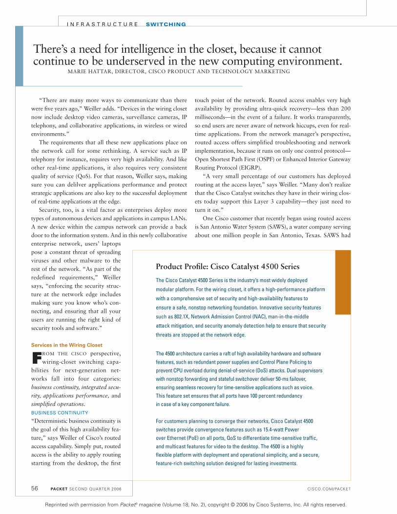
PACKET SECOND QUARTER 2006 CISCO.COM/PACKET
I N F R A S T R U C T U R E SWITCHING
“There are many more ways to communicate than therewere five years ago,” Weiller adds. “Devices in the wiring closetnow include desktop video cameras, surveillance cameras, IPtelephony, and collaborative applications, in wireless or wiredenvironments.”
The requirements that all these new applications place onthe network call for some rethinking. A service such as IPtelephony for instance, requires very high availability. And likeother real-time applications, it also requires very consistentquality of service (QoS). For that reason, Weiller says, makingsure you can delilver applications performance and protectstrategic applications are also key to the successful deploymentof real-time applications at the edge.
Security, too, is a vital factor as enterprises deploy moretypes of autonomous devices and applications in campus LANs.A new device within the campus network can provide a backdoor to the information system. And in this newly collaborativeenterprise network, users’ laptopspose a constant threat of spreadingviruses and other malware to therest of the network. “As part of theredefined requirements,” Weillersays, “enforcing the security struc-ture at the network edge includesmaking sure you know who’s con-necting, and ensuring that all yourusers are running the right kind ofsecurity tools and software.”
Services in the Wiring Closet
FROM THE CISCO perspective,wiring-closet switching capa-
bilities for next-generation net-works fall into four categories:business continuity, integrated secu-
rity, applications performance, andsimplified operations.
BUSINESS CONTINUITY
“Deterministic business continuity isthe goal of this high availability fea-ture,” says Weiller of Cisco’s routedaccess capability. Simply put, routedaccess is the ability to apply routingstarting from the desktop, the first
touch point of the network. Routed access enables very highavailability by providing ultra-quick recovery—less than 200milliseconds—in the event of a failure. It works transparently,so end users are never aware of network hiccups, even for real-time applications. From the network manager’s perspective,routed access offers simplified troubleshooting and networkimplementation, because it runs on only one control protocol—Open Shortest Path First (OSPF) or Enhanced Interior GatewayRouting Protocol (EIGRP).
“A very small percentage of our customers has deployedrouting at the access layer,” says Weiller. “Many don’t realizethat the Cisco Catalyst switches they have in their wiring clos-ets today support this Layer 3 capability—they just need toturn it on.”
One Cisco customer that recently began using routed accessis San Antonio Water System (SAWS), a water company servingabout one million people in San Antonio, Texas. SAWS had
56
There’s a need for intelligence in the closet, because it cannot continue to be underserved in the new computing environment.
MARIE HATTAR, DIRECTOR, CISCO PRODUCT AND TECHNOLOGY MARKETING
Product Profile: Cisco Catalyst 4500 Series
The Cisco Catalyst 4500 Series is the industry’s most widely deployed
modular platform. For the wiring closet, it offers a high-performance platform
with a comprehensive set of security and high-availability features to
ensure a safe, nonstop networking foundation. Innovative security features
such as 802.1X, Network Admission Control (NAC), man-in-the-middle
attack mitigation, and security anomaly detection help to ensure that security
threats are stopped at the network edge.
The 4500 architecture carries a raft of high availability hardware and softwarefeatures, such as redundant power supplies and Control Plane Policing to prevent CPU overload during denial-of-service (DoS) attacks. Dual supervisorswith nonstop forwarding and stateful switchover deliver 50-ms failover, ensuring seamless recovery for time-sensitive applications such as voice. This feature set ensures that all ports have 100 percent redundancy in case of a key component failure.
For customers planning to converge their networks, Cisco Catalyst 4500switches provide convergence features such as 15.4-watt Power over Ethernet (PoE) on all ports, QoS to differentiate time-sensitive traffic, and multicast features for video to the desktop. The 4500 is a highly flexible platform with deployment and operational simplicity, and a secure,feature-rich switching solution designed for lasting investments.
Reprinted with permission from Packet® magazine (Volume 18, No. 2), copyright © 2006 by Cisco Systems, Inc. All rights reserved.

CISCO.COM/PACKET
been using the Hot Standby Router Protocol (HSRP) as afailover system, with fairly traditional Layer 2 access and Layer3 distribution layers. The access switches were dual-homed intodistribution switches, with load bearing on only one link.
“With more bandwidth-intensive applications and moreapplications at the desktop, our utilization on our uplink portswas getting pretty high,” says Darrin Gannaway, senior net-work engineer at SAWS. “Now we’re running EIGRP and let-ting it load balance across both links simultaneously. That wasone of the benefits we saw right away.”
By moving to a routed access layer, SAWS was able to estab-lish a common set of protocols that would run from end to end,from core to campus. With the extra intelligence introduced byrouting, Gannaway and his team enabled faster recovery timeand delivered more intelligent traffic management for SAWSreal-time applications. INTEGRATED SECURITY
The wiring closet must act as a line of defense against anyonecapable of causing network threats. Among the new servicesthat today’s wiring closets need to support are perimeterdefense, identity-based trust and identity management, connec-tivity services, and secure management. Historically, these serv-ices have often arrived on the network via separate appliances.The new trend, however, calls for integrated security to improvemanagement and simplify network operations.
When SAWS deployed routed access at the edge of its net-work, Gannaway was pleased with his newly enabled securitycapabilities. “In the past, when we were at Layer 2, evenunwanted traffic would go all the way up to the distributionlayer before it was filtered. We can employ better security con-trols now, because with the routed access model, I can runACLs [access control lists] at the access layer, right at theentrance point. There’s just more inherent security with havingthe control right there on the port—and [at the same time], therouted model helps reduce our congestion, too.”APPLICATIONS PERFORMANCE
Other vital services that help make up the toolset for this newaccess layer are multicast and QoS capabilities. Layer 3 intelli-gence provided by Cisco Catalyst switches can ensure thatapplications, no matter how delay sensitive or real time innature, always get the throughput they need.
In the SAWS network, one of the most critical businessapplications is a database system called Maximo. “It’s verybandwidth-intensive,” says Gannaway, “and it doesn’t like toshare bandwidth with any other application.” Advanced QoScapabilities were necessary to ensure that Maximo’s mission-critical traffic and real-time IP telephony traffic never experi-enced delays. Furthermore, with the new routed access model,the switches run EIGRP, which supports unequal cost loadbalancing. “Sometimes I don’t want all the traffic being
equally divided,” says Gannaway. With EIGRP, he can cus-tomize it as he chooses.SIMPLIFIED OPERATIONS
In addition to providing the rich services and strong defensesneeded within the next-generation wiring closet, consolidatingon Cisco Catalyst platforms from the core to the wiring closet isvital for consistent services and lower operational costs. Net-works are highly sophisticated, but new technologies, products,and processes help simplify network operations. Some touch-stones of simplicity to aim for include configuration automa-tion, standardization on fewer device platforms and protocols,and intelligent power management.
For Gannaway, network simplification was a welcomebonus of migration to routed access. “Now everything in ourenvironment, whether it’s a router or a Layer 3 switch, relieson routed technology.” He also estimates that the time his team now spends on configuring and maintaining roughly300 network devices has been reduced by 25 to 30 percent.
The Big Picture
WHEN YOU PUT ALL THESE CAPABILITIES together, youget a service that’s always on, with no threats permeat-
ing the information system,” summarizes Weiller. “Then youcombine that with simplification of operation, and you arrive ata very solid foundation that not only improves handling of theapplications you’re already using, but also enables immediateand future deployment of new applications.”
In support of the switching capabilities needed for newwiring-closet requirements, Cisco provides three product lines:• The Cisco Catalyst 3560 and 3750 series provide new base-line services.• The Cisco Catalyst 4500 Series provides higher-grade servicesand higher availability.• The Cisco Catalyst 6500 Series provides the highest levels ofservice, offering data center-grade switching services for thewiring closet. P
PACKET SECOND QUARTER 2006 57
Network Assessment
A good first step in preparing your wiring closet for
next-generation services is a general network
assessment. The Cisco Discovery Tool (cisco.com/go/
partner-discovery), a PC application, can create a
record of all connected network devices, including product
platforms and operating system versions. This
application is available from Cisco account managers
or channel partners.
Reprinted with permission from Packet® magazine (Volume 18, No. 2), copyright © 2006 by Cisco Systems, Inc. All rights reserved.

CISCO.COM/PACKET PACKET SECOND QUARTER 2006 59
wo major events are driving the growthdemands in core capacity: network convergenceand traffic expansion, predominantly fromvideo—the new “killer application”—in its vari-ous forms including IPTV, business video, man-aged video, and Triple Play. Within global serviceprovider markets, the trend is for legacy servicessuch as Frame Relay and ATM switched services tomigrate to Multiprotocol Label Switching (MPLS)-based services (e.g., pseudowires and Carrier Ethernet). Meanwhile, several service providersare converging both their business and residentialaccess network into a single, consolidated next-generation network, demanding ahigher bandwidth capacity core.
The trend toward network con-vergence gives service providers andlarge enterprises an opportunity toreduce the complexity of their net-work by consolidating optical andIP/MPLS network equipment. Core(long haul) and metro optical todayare primarily fully amortized assetsbuilt on legacy SONET/SDH proto-cols. In the early 1990s, SONET and SDH becamethe de facto technology for efficiently and reliablytransporting voice and data using time-divisionmultiplexing (TDM).
SONET/SDH performs three critical functions: itgrooms traffic from slower links, such as T1/E1 andT3/E3, onto higher-speed links; it protects againstfailures and restores a traffic link or path in the eventof a failure; and it provides mechanisms for central-ized administration, monitoring, and control.
DWDM Transport
DENSE WAVELENGTH-DIVISION multiplexing (DWDM)was developed to dramatically increase the informa-tion-carrying capacity of fiber networks by multi-plexing many wavelengths over one physical fiberfor long haul and metro networks. But serviceproviders and large enterprises were put in the posi-
tion of having to invest in multiple layers of networkequipment to meet the increasing IP traffic growth.Three required layers of equipment include anIP/MPLS router, a SONET/SDH add/drop multi-plexing (ADM) transport, and then a DWDM infra-structure. This setup is inefficient to operate,complex to provision and maintain, and requiresconsiderable operational complexity to configure,manage, and troubleshoot.
Today, not surprisingly, both service providersand large enterprises are exploring ways to not onlyreduce their network capital and operating expendi-tures but to accomplish new service rollouts effi-
ciently. Any new solution mustmeet the current business and tech-nical requirements of core andmetro networks.
Because service provider region-al and core points of presence(POPs) are typically many hun-dreds of kilometers apart, routerinterfaces need strong error detec-tion and correction mechanisms.Technical needs for metro networks
are a little less stringent, because distances betweenlocations are shorter, typically less than 100 km. Service providers also want any core solution tointegrate into their existing Operations, Administra-tion, Maintenance, and Provisioning (OAM&P)business processes, so optical networks must con-form to the ITU G.709 standard.
With the current generation of core and aggrega-tion routers terminating multiple Gigabit Ethernetand 10 Gigabit Ethernet of IP traffic, the groomingformerly provided by SONET/SDH is not as widelyrequired. Given the trend toward higher capacityinterfaces such as Gigabit Ethernet, the operationalsupport and traffic protection can now be performedby routers and their associated interfaces throughalternative mechanisms such as G.709 framing andFast ReRoute (FRR). In metro networks, operatorstake advantage of Equal Cost Multipath (ECMP)
Cisco IP over DWDMDELIVERING NETWORK CONVERGENCE FOR CAPACITY GROWTH AND OPERATIONALEFFICIENCIES by errol roberts, ori gerstel, and tony sarathchandra
DWDM ISTHE
unifying technology thatconsolidates IP
applications over a common
transport infrastructure.
T
I N F R A S T R U C T U R E OPTICAL
GE
TT
Y I
MA
GE
S
Reprinted with permission from Packet® magazine (Volume 18, No. 2), copyright © 2006 by Cisco Systems, Inc. All rights reserved.

PACKET SECOND QUARTER 2006 CISCO.COM/PACKET
I N F R A S T R U C T U R E OPTICAL
load balancing or EtherChannel on the router/switch platform.So, there is now an opportunity to reliably and efficiently carryIP traffic directly over the DWDM transport, without the needfor an additional layer of network elements.
Cisco IP over DWDM Solution
IN DECEMBER 2005, CISCO announced an IP over DWDM (IPoDWDM) solution, which takes advantage
of integration between the IP and DWDM network layer ele-ments to help manage expenses, improve network reliability,and increase time to market and speed to service. Thisannouncement included an industry first for core networks:integrated, tunable four-port 10 Gigabit Ethernet and one-port 40-Gbit/s DWDM interfaces for the Cisco CRS-1 CarrierRouting System.
The Cisco CRS-1 1-Port OC-768c/STM-256c TunableWDMPOS Interface Module uses a modulation scheme that provides up to 40 Gbit/s of data throughput across existing10-Gbit/s fiber infrastructures. The 4-Port 10 Gigabit EthernetTunable WDMPHY Interface Module also enables the CiscoCRS-1 to interconnect directly with existing 10-Gbit/s certifiedDWDM systems and fiber plants while providing OAM&P capabilities akin to SONET/SDH at typical Ethernetprice points.
Both modules are fully tunable across the ITU C band with50-GHz spacing and support high-gain Enhanced ForwardError Correction (EFEC), extending reach up to 1,000 km without the additional signal regeneration required by typical core applications.
For metro networks, Ciscooffers a range of integrated plug-gable optical interface modules forCisco Catalyst switches and Cisco7600 Series routers. Cisco DWDMXENPAK supports 10GBASE Eth-ernet, and the Cisco DWDM Giga-bit Interface Converter (GBIC)supports Gigabit Ethernet. Eachcost-effective, high availability inter-face module supports hot insertionand can be ordered in one of 32fixed wavelengths.
These integrated, ITU-compliantinterfaces allow Cisco routers andswitches to interconnect directlywith existing DWDM systemsinstalled at the edge of metro andcore networks without the need foradditional costly transponder equip-
ment at these locations.Rounding out the solution is the Cisco ONS 15454 Multi-
service Transport Platform (MSTP). MSTP supports point-to-point or ring DWDM topology, and integrates photonicswitching via Reconfigurable Optical Add/Drop Multiplexer(ROADM) functionality. Its highly automated capabilitieshave made this platform a leader in the industry for ease ofplanning, deployment, and operation.
Reduced Capital Costs
CISCO’S IPODWDM SOLUTION can eliminate a significantamount of costly network equipment in a POP. Histori-
cally, optical connections within POPs have used standardshort-reach 1,310nm optics (or “gray light”). Long-reach or “colored” optical signals enter the POP typically through 10-Gbit/s SONET/SDH circuits multiplexed via DWDM onto a physical fiber.
Traditionally, these signals are demultiplexed and fed intoracks of transponders that convert them from their currentoptical form to electrical to short-reach optical (this process is called an OEO conversion). The signals are then fed into SONET/SDH cross-connect equipment or a patch panelbefore being terminated on a router or switched through to another POP location.
With transponders integrated directly into the Cisco CRS-1, and with MSTP integrated ROADM functionality,additional external transponders and optical cross-connect
60
The Cisco IPoDWDM solution supports different network management models for service providers, depending on their preference. Because current serviceproviders’ operational organizations are often segmented into IP and transport,OAM&P tools available on the CRS-1 and MSTP provide for both a unified or segmented administration mode.
The transport network operators can access and control the optical network configuration, and the IP operations staff can manage and control the Layer 2 and 3 network configuration on the CRS-1 system. The tools are interoperable withthird-party management systems or service provider-developed operational support systems through the support of TL-1, CORBA, and Simple Network Management Protocol (SNMP) for northbound interfaces. Communication is via Extensible Markup Language (XML), direct command-line interface (CLI),and HTTP/S.
Similarly for metro networks, service providers can choose to have IP networkoperators oversee the passive optical network with integrated pluggable optics onCisco routers and switches. If they require a more flexible metro optical network,they can use MSTP, and transport network operators can monitor and manageboth MSTP and the DWDM pluggable optics.
Integrated or Segmented Management?
Reprinted with permission from Packet® magazine (Volume 18, No. 2), copyright © 2006 by Cisco Systems, Inc. All rights reserved.

CISCO.COM/PACKET
or patch panel equipment are eliminated. This approachreduces capital outlay by as much as 50 percent in some cases and decreases network complexity.
Lowered Operating Expenses
SIMPLIFYING NETWORKS USING a Cisco IPoDWDM solu-tion can also lower network operating expenses for service
providers and large enterprises. Eliminating standalonetransponders decreases power, cooling, and rack space require-ments in a central office or POP. Reducing the number of activenetwork components also decreases potential network failurepoints, which boosts network reliability and lowers mainte-nance costs.
Service providers can further simplify core operations byusing an integrated management approach across the IP andtransport networks (for more on management, see the sidebaropposite page). Cisco has developed network operation lifecycle tools that help facilitate planning, installation, andoperation of metro and core networks. One aspect to thesetools is that they combine wavelength provisioning from theDWDM port on the router through the optical transport layer.Traditionally, changes to traffic patterns must be engineered inadvance, and in-service changes such as adding new filters in the POP need to be done manually and typically disrupt services. Using MSTP, service providers and large enterprisescan remotely add, drop, or change available fiber wavelengthsto respond to changing network conditions or services.
The ability to reconfigure the optical network remotely elim-inates truck rolls, which, in turn increases service flexibility anddecreases operations costs. It also eliminates error-prone man-ual operations that can cause disruptions in existing services.
Improved Network Resilience
THE IPoDWDM FUNCTIONALITY in the Cisco CRS-1 con-forms to the ITU G.709 Optical Transport Network
(OTN) standard, fully supporting the management and per-formance management aspect of typical SONET/SDH connec-tions while interfacing directly into the DWDM layer. With thisenhanced visibility into the DWDM layer, the Cisco CRS-1 canpotentially proactively monitor all optical paths end to end, anddetect gradually degrading wavelength paths caused by envi-ronmental conditions, hardware degradation, or other factors.
By monitoring the Forward Error Correction (FEC) code,the Cisco CRS-1 will identify when the rate of corrected errorsjustifies preemptive action at the IP/MPLS layer. When thatthreshold is reached, the router will trigger reconfigurationbehavior such as FRR, an MPLS function, to switch over to abackup path before the primary path breaks down, avoidingany traffic interruption.
This mechanism is comparable to or better than traditionalSONET/SDH-based failover mechanisms, because it meets orexceeds the 50-ms threshold while using less framing overheadcompared to SONET/SDH.
In the scenario described above, the FEC extends beyondFEC defined in the G.709 standard (GFEC). The router inter-face can be provisioned to use an EFEC. EFEC allows theDWDM signal on Cisco CRS-1 Carrier Routing System inter-faces to reach up to distances of about 1,000 km (621 miles)without optical regeneration—an industry first.
For metro applications, Cisco ITU pluggable optical inter-face modules support Digital Optical Monitoring (DOM), anindustry-wide standard that defines a digital interface to accessand monitor the operating parameters of transceivers. WithDOM, metro network operators can perform in-service
PACKET SECOND QUARTER 2006 61
Cisco IPoDWDM Framework
Access/Aggregation
Access/Aggregation
Cisco7600
CiscoCatalyst6500
CiscoCatalyst6500
IPoDWDM Metro IPoDWDM Metro
Cisco CRS-1
Cisco CRS-1
Cisco ONS15454 MSTP
Cisco ONS15454 MSTP
Core Metro/EdgeMetro/Edge
IPoDWDM Core
CiscoXR 12000
CiscoXR 12000
Cisco7600
OPTICAL ADVANTAGE The Cisco IPoDWDM solution integrates long-haul transponders within the CRS-1 and provides managed wavelengths across the ROADM for scalable bandwidth, reduced complexity, and faster time to market with services.
Reprinted with permission from Packet® magazine (Volume 18, No. 2), copyright © 2006 by Cisco Systems, Inc. All rights reserved.

PACKET SECOND QUARTER 2006 CISCO.COM/PACKET
I N F R A S T R U C T U R E OPTICAL
transceiver monitoring and troubleshooting operations, ensur-ing a more available yet highly cost-effective network.
In addition to the performance monitoring characteristics ofthe ITU service interfaces provided by DOM and G.709, anintelligent photonic layer based on MSTP will provide end-to-end wavelength power management and visibility.
IPoDWDM in Practice
SERVICE PROVIDERS AND SOME large enterprises arealready using Cisco IPoDWDM solutions to simplify their
networks and reduce expenses, improve network reliability, andincrease speed, scalability, and flexibility for IP-rich mediaapplications. Comcast Cable, for example, is the largest USprovider of cable services, and is expanding its cable operationsto deliver digital services, provide faster Internet and IP-enabledphone service and innovative programming.
“Comcast’s and Cisco’s shared vision of integrated 10-Gbit/sand 40-Gbit/s DWDM interfaces was one of the key reasons weselected the CRS-1,” according to Vik Saxena, Comcast Directorof IP Architecture. “As we move to transport all services over IP,including broadcast video and video on demand, cost-effective-ness, scalability, reliability, and service flexibility become critical.By meeting these important needs, Cisco’s CRS-1 is an ideal platform on which to base our service growth.” P
62
ERROL ROBERTS is a Cisco Distinguished Systems Engineer with a
focus on optical and data center technologies. He can be reached
ORI GERSTEL has been leading optical networking architecture
efforts for 15 years and currently manages the advanced technol-
ogy team in Cisco’s Carrier Routing Business Unit. He can be
reached at [email protected].
TONY SARATHCHANDRA is a product marketing manager with
the service provider routing and switching team at Cisco. His
current focus is in the core routing arena encompassing the Cisco
CRS-1 platform. He can be reached at [email protected].
Further Reading• Cisco IPoDWDM Solution for IP NGN
cisco.com/packet/182_7b1
• Cisco CRS-1 Carrier Routing System
cisco.com/packet/182_7b2
• Cisco ONS 15454 Multiservice Transport Platform
cisco.com/packet/182_7b3
Reprinted with permission from Packet® magazine (Volume 18, No. 2), copyright © 2006 by Cisco Systems, Inc. All rights reserved.

CISCO.COM/PACKET PACKET SECOND QUARTER 2006 63
oo often in the Internet world, the people who need protection mostare those least likely to have it. People who consider computers intuitive have no trouble finding and load-ing antivirus, antispyware, URL filtering, and other safeguards. But many people do not know how andtherefore do not do it—even when the software is made easily available by their ISP. • That was the expe-rience of Plala Networks, headquartered in Tokyo. Its goal for the three-quarters of its 2 million sub-scribers who have broadband service is to enable them to use the Internet “securely and with peace ofmind.” Initially Plala offered e-mail virus checking and encryption as optional services, but found thatthese services were adopted only by customers who understood to a certain degree the dangers of theInternet. Novices without that understanding typically didnot opt for the protection that these services provided.
According to Katsumi Nagata, director of Plala Networksand general manager of System Development and NetworkEngineering, “There is an increasing number of people whodo not know what a virus is or what they should do to preventchildren from accessing pornographic, violent, or other inap-propriate sites. However, we would like such people to use theInternet more securely. To accomplish this goal, a potentialsolution is useless unless it is made the default or offered freeof charge. We wanted to make a system in which our least-experienced users can be protected from the outset.”
Plala’s solution was to eventually install Cisco Service Control Engine (SCE) 2020 systems at all regional accessaggregation points. On this platform, the company makesavailable its “Net Barrier Basic” service, which includes URLand packet filtering. These two features help protect usersfrom inappropriate Websites and content and assist in detect-ing security breaches. The platform yields other benefits aswell. Plala can also limit applications that consume largeamounts of bandwidth, so all subscribers find high-speedInternet access readily available.
In 2003 Plala Networks, which has the highest customersatisfaction rating among Japanese broadband providers,began working toward providing all subscribers with a dra-matically enhanced quality experience. Plala’s first step was tooptimize its network by managing peer-to-peer (P2P) trafficusing the Cisco SCE 1010 Service Control Engine (previously
Service Control Benefits ISPJAPAN’S PLALA NETWORKS DELIVERS SECURITY AND “PEACE OF MIND” TO ALL ITS BROADBAND CUSTOMERS.
T
S E R V I C E P R O V I D E R S
GOT HERCOVERED
URL and packet filtering help Plala
keep harmful content and
security breachesaway from its subscribers.A
CH
ILL
E B
IGL
IAR
DI
PH
OT
OG
RA
PH
Y
Reprinted with permission from Packet® magazine (Volume 18, No. 2), copyright © 2006 by Cisco Systems, Inc. All rights reserved.

PACKET SECOND QUARTER 2006 CISCO.COM/PACKET
S E R V I C E P R O V I D E R S
known as the SE 1000). Plala used the SCE initially to discoverwhat types of traffic were traveling over its network and tyingup bandwidth—finding a good deal of congestion from P2P file-sharing services—and then to impose limits on those applica-tions. Everyone is affected when a few users consume morethan their fair share of resources for P2P downloads. “With theCisco Service Control Solution, we were able to create an envi-ronment that allows everyone to share resources fairly,” saysShinya Adachi, manager of the Network Engineering Depart-ment at Plala.
Application-Level Packet Control with SCE 2020
THE SCE 2020, Cisco’s flagship model for its service controlsolutions, uses deep packet inspection to identify protocols
for voice over IP, video, gaming, instant messaging, P2P filesharing, and others—any and all applications found in a typicalbroadband provider’s network.
“The system can identify over 900 protocols, anywherefrom simple, port-based ones to the more advanced protocolsthat require Layer 7 information, such as P2P application trafficand voice over IP,” says Moti Beharav, Cisco theater managerfor SCE business in Japan. Because many new protocols usewell-known ports for masking or use port-hopping, Beharavadds, it’s not always possible to know what application is actu-ally being used without access to the Layer 7 information.
“We’ve seen applications such as P2P and video on port 80originally used for HTTP, for example, and a lot of other appli-cations on ports that weren’t intended for them.”
The SCE 2020 controls and limits bandwidth by applyingpolicy rules to application traffic on a per-subscriber basis ifrequired. For example, it can limit the bandwidth used for filesharing while giving priority to voice over IP, video, or gaming—any application that’s sensitive to delays, Beharav explains. Itcan also redirect traffic that violates the programmed policies.
“The Cisco SCE 2020 can perform judgments at an applica-tion level, making it possible to block traffic that is spoofing theport number,” says Yasuhiro Horike, manager of the SystemDevelopment Department at Plala. “With this ability, we canprotect our network from performance degradations. High per-formance is a vital contributor to our reputation for leadingcustomer satisfaction.”
A Safe, Well-Lit Internet Experience
NEXT, PLALA TURNED TO the matter of providing better secu-rity for all its subscribers, and in 2005 instituted clientless
access to its Internet service, simultaneously upgrading to theSCE 2020. In its network, a Cisco SCE 2020 is located at eachpoint where regional access is aggregated and is connected to amanagement server (see figure).
Now, as Adachi explains, “Our IP addresses change each
64
NET BARRIER BASIC Plala’s default security service depends on installing the Cisco SCE 2020 at access aggregation points, linked to a managementserver. Together the two negotiate ever-changing IP addresses crucial to provisioning the service.
The Plala Broadband Platform
Internet
Plala Networks
ManagementServer
AdditionalServices
CiscoSCE2020
B FLET’S(NTT East/West)
B FLET’S(NTT East/West)
B FLET’S(NTT East/West)
Reprinted with permission from Packet® magazine (Volume 18, No. 2), copyright © 2006 by Cisco Systems, Inc. All rights reserved.

CISCO.COM/PACKET
time a user connects. So the managementserver linked to the SCE performs the roleof identifying each customer, even whenthe IP address changes, and sends the cus-tomer’s settings to the SCE 2020 so it willprovide the appropriate services.”
The Cisco SCE 2020 can serve sub-scribers in this network configurationbecause it is subscriber-aware. It is able toobtain real-time information on the IPaddress associated with a given subscriberat any given time and then take action orenforce policies for each subscriber and theapplication he or she is using. This capabil-ity allows the SCE 2020 to deliver Plala’sNet Barrier Basic service, which includesURL and packet filtering, even thoughusers have not installed any protectiveclient software on their PCs—and to pro-vide these features as a default service, freeof charge.
The URL filtering enables Plala to blockaccess to pornographic sites or sites with inappropriate content.Packet filtering enables the company to detect behavior thatindicates the presence of worms and viruses and take steps toseal them out of the network. The filtering is transparent anddoes not affect network performance. “Since we first used theCisco SCE 1010 for bandwidth control, we have valued its abil-ity to deliver extremely high throughput,” says Horike. “Nowthat we’ve moved to the SCE 2020, we do not experience anyreductions in performance even when using URL filtering andpacket filtering.” The purpose-built system can track and man-age 2 million concurrent unidirectional flows, and the overallsolution is designed to scale even higher.
The system gives Plala Networks a platform for addingfuture security and other services.
“We would like to provide security measures that allow usto logically determine responses for any discovery of a securityproblem or vulnerability,”according to Nagata. “Wewould also like to offer asystem that provides evengreater protection by warn-ing customers of infectionby worms or viruses andnotifying them of how torespond to the situation. Byproviding more secure serv-ices, we would like to letpeople use the Internet with
a greater sense of peace of mind.” In step with Plala’s goal, the Cisco SCE 2020 can identify
patterns and behaviors that indicate worms and viruses. “If itfinds a behavior—say a massive amount of outgoing e-mailtraffic—that falls into the category of a worm,” Beharavexplains, “the provider can redirect the traffic to warn the cus-tomer of the infection and ask him or her to download the cor-rect patch from a security Website. In the meantime, the systemprotects the rest of the network.”
Commitment to Security
PLALA’S COMMITMENT TO security is evident from its receiv-ing both the Information Security Management System
certification from BRS, an international accreditation body,and the Privacy Mark certification, a Japanese standard forprotecting personal information. These awards require thecompany to continually review all operational and systemaspects of internal security.
Customers are happy with its service, and Plala finds itselfwith a platform for growth. “In a way, Net Barrier Basic is a uniform service,” Nagata says. “The main theme was toprovide the service by default and free of charge, but someusers want a more advanced service. For example, with URLfiltering, some people want greater customization and basi-cally wish to block violence and pornography but still allowcertain items. The system that we have created will providethe necessary foundation for delivering this level of cus-tomized service.” P
PACKET SECOND QUARTER 2006 65
Deploying the Cisco SCE 2020 has yielded several business benefits for Plala Networks:
A consistent broadband experience. In controlling consumption of bandwidth by P2P file sharing, Plala has created a network in which users can fairly share resources.
Predictable, safe broadband access. With its Net Barrier Basic service, intrusions and worms can be blocked at the application level, and URL filteringdenies access to inappropriate Websites.
Optimized support services. As fewer users need technical support to get rid ofviruses and other intruders and to block harmful content, support staff is freed upto deal with other issues.
A foundation for customized services. The combination of the managementserver and the Cisco SCE 2020 enables Plala to identify each user, providing thefoundation to deliver services tailored for individual customers.
Solid Platform for the Future
• Cisco SCE 2000 Series
Service Control Engine
cisco.com/packet/182_8b1
• Cisco SCE 2000 Series
White Papers
cisco.com/packet/182_8b2
Further Reading
Reprinted with permission from Packet® magazine (Volume 18, No. 2), copyright © 2006 by Cisco Systems, Inc. All rights reserved.

CISCO.COM/PACKET PACKET SECOND QUARTER 2006 67
videnced by the joint ventures betweenmajor cable providers and mobile carriers, multiplesystem operators (MSOs) are serious about addingmobile services to their cable bundles. Maintainingparity with telcos (with strong mobile offerings) andchanges in consumer media consumption patternshave brought attention to the technology alterna-tives for multimedia services over cable infrastruc-tures. More and more subscribers want their mobilephones to serve as their primary phones and wantthe ability to access Internet, video, and other multi-media services from their handsets, PCs, or TVs.
Talk of “triple play” services—data, voice, andvideo—has evolved to “quadruple play” with theaddition of wireless services. But it would be moreaccurate to describe the vision in terms of delivering“triple play on the move.” With that vision comesthe desire to introduce blended services such asvideo phone, multimedia chat, and gaming to myriad devices.
To remain competitive, MSOs must provide avariety of new multimedia services in the near term,and in a faster, more efficient way. Examples ofupcoming services include “one-number” phoneservice, unified messages (combining e-mail andvoicemail), dual-mode cellular Wi-Fi handsets, videoon demand (VoD) streaming to cell phones, andcross-device functions such as viewing caller IDusing a set-top box (STB).
MSOs need an infrastructure that supports awide range of devices. Services must support pres-ence (the ability to know if a person is available forcommunications) and identity management and per-sonalized services. Furthermore, high-quality voiceand video applications require built-in quality ofservice (QoS) capabilities in the network. Even morechallenging, MSOs must ensure that they also con-tinue to provide their existing primary-line voiceservices without interruption.
As with any technology that spans multiple ven-dors, network architectures, and media, standardsmust play a vital role in meeting the challenges faced
by MSOs. There is a functionality gap betweentoday’s PacketCable 1.x specification and what isneeded. In response, CableLabs and a consortium ofparticipating industry players have evolved the Net-work Call Signaling (NCS) standard and developedPacketCable 2.0.
PacketCable 1.x defines a centralized architecturebased on a variant of the Media Gateway ControlProtocol (MGCP), called NCS. Call managementservers (CMSs or softswitches), media gateways,and media terminal adapter (MTA) endpoints areused to mimic the functionality of the PSTN. Thisstandard supports only MTA endpoints (for con-necting legacy phones and fax machines) and doesnot go beyond POTS over IP at the application andservice levels. PacketCable 2.0, by contrast, willinclude Session Initiation Protocol (SIP) to achieve adistributed multimedia signaling architecture withpresence and identity capabilities. A broad range ofSIP endpoints are supported within a PacketCable
2.0 environment, including SIP MTAs, SIP phonesand soft phones, STBs, video phones, PCs and gameconsoles, and dual-mode cellular Wi-Fi handsets.
SIP, however, is a protocol and not a networkarchitecture. A consortium of players in the mobilemarket, the 3rd Generation Partnership Project(3GPP), developed the IP Multimedia Subsystem(IMS) specification—a standardized network archi-tecture for SIP-based services. It has been adopted byother standards bodies, major carriers, and equip-ment vendors alike. While IMS originated in the
IMS Migration Primer for MSOsHOW TO TRANSITION TO NEW MULTIMEDIA AND FIXED MOBILE APPLICATIONS by jonathan rosenberg
E
S E R V I C E P R O V I D E R S
IMS allows MSOsto take full advantage of their existing IP core network and avoid overloading the cable infrastructure.
Reprinted with permission from Packet® magazine (Volume 18, No. 2), copyright © 2006 by Cisco Systems, Inc. All rights reserved.

PACKET SECOND QUARTER 2006 CISCO.COM/PACKET
S E R V I C E P R O V I D E R S
mobile market, it uses SIP to support services across virtuallyany access technology.
IMS has evolved so that multiple access technologies can beblended: Wi-Fi, WiMAX, DSL, broadband cable access, andeven enterprise-level T1. The IMS architecture includes anagnostic control plane that can work over cable or mobile net-works, and serves to bridge packet, circuit, wired, and wirelessworlds. A layered approach decouples the network infrastruc-ture from services with a standardized, horizontal approach, andenables a flexible platform that makes it easier for providers torespond rapidly to new service requirements and the need to bet-ter address service personalization (e.g., self-subscription, buddylists) and control (e.g., QoS, class of service, charging, security,content filtering).
Because of the momentum of SIP and IMS, it is logical thatMSOs and CableLabs would decide to adopt SIP and IMS as afoundation for next-generation networking services as specifiedin the evolving PacketCable 2.0 standard. PacketCable Multi-media (PCMM) will be the mechanism for implementing QoSfor SIP services as part of PacketCable 2.0. Outside of Packet-Cable 2.0, PCMM can also provide QoS for non-SIP or non-IMS multimedia applications.
Migrating to IMS/SIP Multimedia Services
PROTECTING CURRENT INVESTMENTS and leveraging les-sons already learned with PacketCable 1.x requires a
gradual, evolutionary path to get to a PacketCable 2.0 infra-structure. Such a path can be realized by using current businessneeds to define and drive the addition of incremental capabili-ties to existing networks. The evolution to an IMS architecturewill involve incorporating the three core IMS control functions(see figure). The Serving Call Session Control Function
(S-CSCF), also referred to as the home proxy or subscriberproxy function, manages access to the subscriber database anduses the information stored in that database to invoke featuresand applications in response to subscriber requests. The Inter-
rogating Call Session Control Function (I-CSCF) controls theboundary to the network and is responsible for routing requeststo the right S-CSCF. The Proxy Call Session Control Function
(P-CSCF) acts as an interface to clients, secures the link to theclient, and facilitates roaming.
These IMS control functions sit on top of the IP transportplane. For GSM mobile communications, the IP layer includesthe Gateway GPRS Support Node (GGSN) and Serving GPRSSupport Node (SGSN) mobile access routers. On the cable
68
IMS for PacketCable 2.0
AS
ISC
AS AS
ISC
ISC
ISC
SCIM
MRF S-CSCF
HSS
PDF I-CSCFHLR
SGW P-CSCF BGCF/MGCF SEG
MGW MGW
GGSN SGSN
Application/Service Plane
Control Plane
IP Transport Plane
Radio Access NetworkHFC Access Network
PSTN
IP Core
IMSFunctions
THE IMS PROMISE By introducing a common subscriber data model and standardized interfaces for application servers, IMS has the elements to create a flexible platform for launching new services.
Reprinted with permission from Packet® magazine (Volume 18, No. 2), copyright © 2006 by Cisco Systems, Inc. All rights reserved.

CISCO.COM/PACKET
side, this layer includes the HFC access network components.In the application/service layer of the network, an IMS archi-tecture introduces the IMS Service Control (ISC) interface forconnecting the S-CSCF to a Service Capability InteractionManager (SCIM). The SCIM performs feature interactionmanagement, and connects to application servers using thesame ISC interface.
The IMS is an important part of a service provider’s net-work, providing a control plane for SIP-based services. How-ever, IMS is only part of the story. A complete IP-basednext-generation network is composed of three distinct layers:the network layer, which includes the entirety of the IP network; the service control layer (of which IMS is a part);and the applications that reside on top. The control layerneeds to provide a link between the applications and theunderlying IP network for both SIP and non-SIP applications.The vast majority of IP-based applications today are not SIP-based, and a layer of service control is needed for these, too.To this end, MSOs require a Service Exchange Framework(SEF) that supports a transparent migration to IMS, with fullsupport for IMS and non-IMS endpoints. With a robust serv-ice exchange solution for IMS, cable MSOs will be able tosupport multiple applications on a common infrastructurethat supports both SIP and PacketCable 1.x, while offeringsubscribers a customized service experience based on real-time state information and profile preferences.
The importance of IMS for future services, and the impor-tance of growing and protecting existing PacketCable 1.x serv-ices, calls for a phased introduction of IMS. Consider thefollowing example as one path an MSO might take.
Phase 1: PSTN Bypass
BY MAKING BETTER USE OF MEDIA gateway controllers(MGCs), MSOs can move more of their long-distance
voice service off the PSTN and onto the IP network, whichreduces the dependencies on competing carriers and reducescosts simultaneously. First, the softswitch must be decomposedinto a subscriber-facing CMS and a PSTN-facing MGC. By sep-arating the softswitch into these components, the network canbe more easily scaled for better overall network efficiencies.
Once PSTN and subscriber control functions are separated,MSOs can then introduce a combined I-CSCF and BreakoutGateway Control Function (BGCF). (BGCF is the interface forinterconnecting IMS with legacy networks.) This IMS elementallows PSTN interconnects to be shared by multiple CMSs.CMSs can be added as needed, allowing the network to scalewith increases in subscribers. PSTN interconnects can be addedas traffic requires. Calls between subscribers can stay on-net,routed to the correct terminating CMS by the I-CSCF function.This configuration offloads calls from the PSTN.
Phase 2: Add SIP-Based Services
PHASE 2 INTRODUCES NEW REVENUE streams for IMS-enabled services, which can include capabilities such as
voice dialing, caller ID on a STB, and click to dial. New SIP-based services can now be rapidly introduced and delivered byconnecting new application servers to the CMSs. Multipleapplication servers from multiple vendors can all interconnectto CMSs over the IMS ISC interface, a SIP-based interface foruse with application servers. Here, a true blending hasoccurred. The ISC interface from IMS and PacketCable 2.0 isused, but to provide features to existing PacketCable 1.x end-points. This allows a minimally disruptive transition with noforklift upgrades and no replacement of endpoints.
Phase 3: Business/Commercial Voice
IN THIS PHASE, AN MSO might focus on the business needsrelated to expanding the commercial subscriber base. MSOs
can build on the IMS environment by adding SIP endpoints(e.g., the Linksys SPA9000, a residential standalone box thatprovides a small, integrated IT PBX solution with support forup to 16 lines, or SIP MTAs). To interface to these SIP end-points, the P-CSCF is introduced, which provides PCMM QoSfeatures that ensure business-grade voice services. The P-CSCFconnects to the underlying CMTSs and policy servers to pro-vide QoS and security functions. This phase also uses the in-place CMSs, allowing them to control the SIP endpoints.Through the ISC interface, the SIP endpoints also gain accessto the new applications deployed from the previous step.With the completion of Phase 3, an MSO has introduced asignificant portion of an overall IMS architecture.
Phase 4: Fixed Mobile Convergence
THE MOVE TOWARD FIXED MOBILE convergence involvessupport for dual-mode handsets and the introduction of
two servers. The dual-mode devices can communicate over thecellular network, or act as a new endpoint on the IP network.The Home Subscriber Server (HSS) manages subscriber datauniformly between cellular and IP. The Handoff Serverruns on top of the ISC interface and provides a seamless experi-ence when subscribers move from cellular to a Wi-Fi network.
The CMS remains the functional center of the network, butwith the introduction of the HSS, has added the Cx and Shinterfaces defined by the IMS, taking it a step further to becom-ing a complete S-CSCF. By continuing to take advantage of theCMS in each phase, MSOs accomplish a truly evolutionarymove to IMS. P
PACKET SECOND QUARTER 2006 69
DR. JONATHAN ROSENBERG is a Cisco Fellow in the Routing and
Service Provider Technology Group at Cisco. He can be reached
Reprinted with permission from Packet® magazine (Volume 18, No. 2), copyright © 2006 by Cisco Systems, Inc. All rights reserved.

CISCO.COM/PACKET PACKET SECOND QUARTER 2006 71
T H E L A T E S T P R O D U C T S
CALABILITY
and consolidation are bywords for the Cisco MDS 9513 MultilayerDirector Switch. Built for enterpriseand service provider data centers,this mighty platform can scale up to528 ports with a choice of 1, 2, 4, and 10 Gbit/s of Fibre Channel—the highest speeds for Fibre Channel-over-IP (FCIP), SCSI-over-IP (iSCSI), and Fibre Connection(FICON) all in one system.
“The Cisco MDS 9513 is a greatcore switch for consolidating multiple SANs [storage-area net-works] into one infrastructure,”says Alison Conigliaro-Hubbard,senior manager of storagenetworking at Cisco.
The modules used in the first-generation Cisco MDS 9000switches—for different types of
Storage Switch Redefines ScalabilityNEW CISCO MDS 9513 PACKS THE INDUSTRY’S HIGHEST PORT DENSITY WITH UP TO 10 GBIT/S by gene knauer
STORAGESTUD
The MDS 9513sports 10-Gbit/s
speeds on different blades
in the same switch, and a
choice of storage transport.
s
Continued on page 76
speeds+feedsbeyond
Reprinted with permission from Packet® magazine (Volume 18, No. 2), copyright © 2006 by Cisco Systems, Inc. All rights reserved.
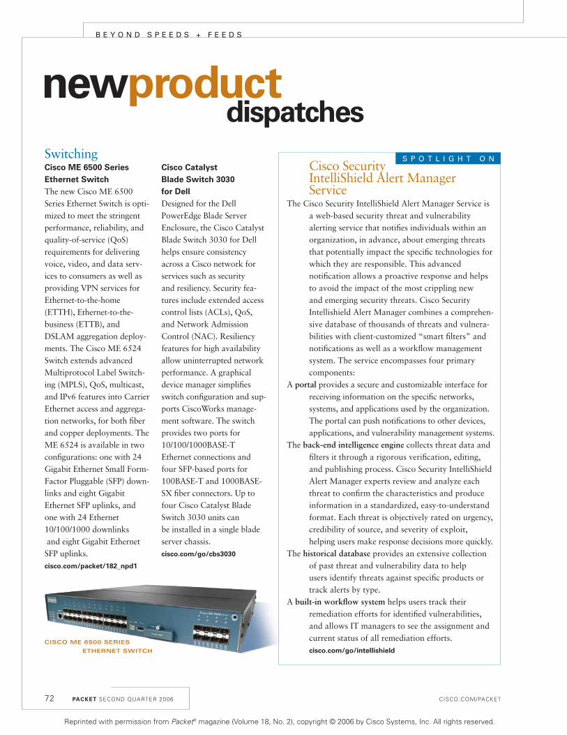
SwitchingCisco ME 6500 Series
Ethernet Switch
The new Cisco ME 6500Series Ethernet Switch is opti-mized to meet the stringentperformance, reliability, andquality-of-service (QoS)requirements for deliveringvoice, video, and data serv-ices to consumers as well asproviding VPN services forEthernet-to-the-home(ETTH), Ethernet-to-the-business (ETTB), andDSLAM aggregation deploy-ments. The Cisco ME 6524Switch extends advancedMultiprotocol Label Switch-ing (MPLS), QoS, multicast,and IPv6 features into CarrierEthernet access and aggrega-tion networks, for both fiberand copper deployments. TheME 6524 is available in twoconfigurations: one with 24Gigabit Ethernet Small Form-Factor Pluggable (SFP) down-links and eight GigabitEthernet SFP uplinks, andone with 24 Ethernet10/100/1000 downlinksand eight Gigabit EthernetSFP uplinks.cisco.com/packet/182_npd1
Cisco Catalyst
Blade Switch 3030
for Dell
Designed for the Dell PowerEdge Blade ServerEnclosure, the Cisco CatalystBlade Switch 3030 for Dellhelps ensure consistencyacross a Cisco network forservices such as security and resiliency. Security fea-tures include extended accesscontrol lists (ACLs), QoS,and Network AdmissionControl (NAC). Resiliencyfeatures for high availabilityallow uninterrupted network performance. A graphicaldevice manager simplifiesswitch configuration and sup-ports CiscoWorks manage-ment software. The switchprovides two ports for10/100/1000BASE-T Ethernet connections andfour SFP-based ports for100BASE-T and 1000BASE-SX fiber connectors. Up tofour Cisco Catalyst BladeSwitch 3030 units can be installed in a single bladeserver chassis.cisco.com/go/cbs3030
newproductdispatches
Cisco Security IntelliShield Alert Manager Service
The Cisco Security IntelliShield Alert Manager Service isa web-based security threat and vulnerability alerting service that notifies individuals within anorganization, in advance, about emerging threatsthat potentially impact the specific technologies forwhich they are responsible. This advanced notification allows a proactive response and helpsto avoid the impact of the most crippling new and emerging security threats. Cisco Security Intellishield Alert Manager combines a comprehen-sive database of thousands of threats and vulnera-bilities with client-customized “smart filters” andnotifications as well as a workflow managementsystem. The service encompasses four primarycomponents:
A portal provides a secure and customizable interface forreceiving information on the specific networks, systems, and applications used by the organization.The portal can push notifications to other devices,applications, and vulnerability management systems.
The back-end intelligence engine collects threat data andfilters it through a rigorous verification, editing,and publishing process. Cisco Security IntelliShieldAlert Manager experts review and analyze eachthreat to confirm the characteristics and produceinformation in a standardized, easy-to-understandformat. Each threat is objectively rated on urgency,credibility of source, and severity of exploit, helping users make response decisions more quickly.
The historical database provides an extensive collectionof past threat and vulnerability data to help users identify threats against specific products ortrack alerts by type.
A built-in workflow system helps users track their remediation efforts for identified vulnerabilities,and allows IT managers to see the assignment andcurrent status of all remediation efforts. cisco.com/go/intellishield
S P O T L I G H T O N
PACKET SECOND QUARTER 2006 CISCO.COM/PACKET
B E Y O N D S P E E D S + F E E D S
72
CISCO ME 6500 SERIES
ETHERNET SWITCH
Reprinted with permission from Packet® magazine (Volume 18, No. 2), copyright © 2006 by Cisco Systems, Inc. All rights reserved.

Security and VPNsCisco Security Manager
The Cisco Security Managersoftware allows administra-tors to centrally provisiondevice configurations andsecurity policies for firewalls,VPNs, and intrusion preven-tion systems. The softwareprovides distinct views at thedevice, policy, and topologylevels to meet different opera-tional preferences and needs.Other features include policysharing for efficiency and policy distribution for greaternetwork resilience. CiscoSecurity Manager is effectivefor managing small networkswith fewer than ten devices,but also scales to efficientlymanage large-scale networkswith thousands of devices.Scalability is achievedthrough intelligent, policy-based management tech-niques that can simplifyadministration. For more onCisco Security Manager, see page 48.cisco.com/go/csmanager
Cisco ASA 5500 Series
Adaptive Security Appli-
ance: New Services Mod-
ule and Software Version
The Cisco ASA 5500 SeriesAdaptive Security Applianceis a modular platform thatprovides security and VPNservices in enterprise net-works. The new ContentSecurity and Control SecurityServices Module (CSC-SSM)delivers comprehensive threatprotection and content con-trol services. These servicesinclude antivirus, anti-spy-ware, file blocking, anti-spam, anti-phishing, URL
blocking and filtering, andcontent filtering. Version 7.1of the Cisco ASA 5500 Seriessoftware delivers new featuresfor Secure Sockets Layer (SSL)VPNs including customizableuser portals; Web contenttransformation for compati-bility with Java, ActiveX,complex HTML, andJavaScript; and scalability upto 5,000 concurrent users.For more on the ASA 5500Series module and version 7.1software, see page 48.cisco.com/go/asa
Voice and VideoCisco Unified Personal
Communicator
The Cisco Unified PersonalCommunicator softwaretransparently integrates manycommunications applicationsand services into a singledesktop computer applica-tion. It provides quick andeasy access to tools for voiceand video calls, Web confer-encing, call management,directories, voice messages,and presence information.These tools help users com-municate effectively andwork more productively. Seerelated article on page 36.cisco.com/packet/182_npd2
Cisco AS5400XM
and AS5350XM Universal
Gateways: New
High-Density Packet
Voice/Fax Feature Card
The new High-Density PacketVoice/Fax Feature card forCisco AS5400XM and CiscoAS5350XM Universal Gateways provides scalabilityfrom 64 to 384 channels. TheCisco AS5400XM now offers
increased voice call capacityup to a full channelized T3(CT3) with all codecs, and the Cisco AS5350XMoffers 12-E1, 16-T1, and CT3 configurations using the G.711 codec. The High-Density PacketVoice/Fax Feature Card intro-duces support for the Adap-tive Multi-Rate Narrow Band(AMR-NB) codec, mediaauthentication and encryp-tion using Secure Real-TimeTransport Protocol (SRTP),and modem relay.cisco.com/packet/182_npd3
cisco.com/packet/182_npd4
Cisco Unified
Presence Server
The Cisco Unified PresenceServer software collects infor-mation about a person’s cur-rent availability andcommunications capabilitiesto help users connect withcolleagues more efficiently.Cisco Unified Presence Serverprovides the presence infor-mation used by Cisco UnifiedPersonal Communicator andCisco IP Phone Messenger. It also supports MicrosoftOffice Communicator func-tions for click-to-dial andphone monitoring. See related
article on page 36.cisco.com/packet/182_npd5
Cisco Unified Customer
Interaction Analyzer
The Cisco Unified CustomerInteraction Analyzer is amanaged service that helpscontact centers analyze eachinteraction that occursbetween customers and serv-ice representatives. Customerinteractions are captured onsite and transferred to a dedi-cated, secure hosted facilityfor storage, retrieval, andevaluation. Through a Web-based interface, evaluationresults are presented on tailored reports or dash-boards that help contact center managers withemployee coaching and callscripts. See related article on page 36.cisco.com/packet/182_npd6
Cisco Unified IP Phones
7900 Series: New
Video Phone Model and
Enhanced SIP Feature and
Gigabit Ethernet Support
The Cisco Unified IP Phone7985G is a personal desktopvideo phone that enablesinstant, face-to-face commu-nications. It incorporates the
CISCO.COM/PACKET PACKET SECOND QUARTER 2006 73
CISCO AS5400XM HIGH-DENSITY
PACKET VOICE/FAX FEATURE CARD
Reprinted with permission from Packet® magazine (Volume 18, No. 2), copyright © 2006 by Cisco Systems, Inc. All rights reserved.

newproductdispatches
PACKET SECOND QUARTER 2006 CISCO.COM/PACKET74
camera, LCD screen, speaker,keypad, and handset into asingle, easy-to-use unit. Thenew Cisco Unified IP Phone7971G-GE (color touch-screen display), 7961G-GE(grayscale with six program-mable buttons), and 7941G-GE (grayscale with twoprogrammable buttons)include a Gigabit Ethernetport for integration to a PCor desktop server. When used with Cisco Unified CallManager 5.0, the CiscoUnified IP Phones 7971G-GE,7970G, 7961G, 7941G, and7911G now supportenhanced Session InitiationProtocol (SIP) services. Seerelated article on page 36.cisco.com/packet/182_npd7
Cisco Unified Wireless IP
Phone 7920 Multi-Charger
The Cisco Unified Wireless IPPhone 7920 Multi-Chargercan charge up to six CiscoUnified Wireless IP Phone7920s and six batteries simul-taneously. The multi-chargeris ideal for environmentswhere employees work inmultiple shifts and need tokeep their phones charged
throughout the day. The unithas a flexible design for placing on a desk or mount-ing on the wall.cisco.com/packet/182_npd8
Cisco 7800 Series Media
Convergence Server:
Call-Processing Appliance
on New Models
New models of Cisco 7800Series Media ConvergenceServers (MCS) provide a call-processing appliance withpreinstalled Cisco UnifiedCallManager 5.0 software.The server appliance is fullyoperational upon startup,requiring entry of only a fewparameters such as IP addressand domain. The new modelsoffer choices for single ordual processors and can serveas many as 7,500 IP phonesper appliance and up to30,000 IP phones per cluster. cisco.com/packet/182_npd9
Network ManagementCiscoWorks Interface
Configuration Manager
The CiscoWorks InterfaceConfiguration Manager soft-ware provides graphical con-
figuration and reporting capa-bilities to help manage accessports on Cisco switches,reducing the time and effortneeded to roll out consistentbulk configurations across thenetwork. The software pro-vides tools to simplify configu-ration of Layer 2 NetworkAdmission Control (L2 NAC)in conjunction with the CiscoWorks LAN manage-ment solution, reducing oper-ator errors and increasingnetwork availability. It pro-vides a L2 NAC ReadinessReport to help optimize net-work research and planning.NAC technologies such as L2802.1x, L2 IP, AAA fail open,MAC exceptions, PBACLS,and RADIUS server configura-tion are supported. The con-figurations can be saved,copied, and edited, freeing uptime for network administra-tors. Customized device andport groups can be createdand re-used in multiple config-urations.cisco.com/go/cwicm
Cisco Router and
Security Device Manager
Version 2.3
The Cisco Router and Secu-rity Device Manager (SDM)is a Web-based device-management tool for CiscoIOS Software-based routers.SDM version 2.3 deliverscomprehensive support for simplified managementand real-time performancemonitoring of concurrentservices on Cisco IntegratedServices Routers. Key
features include integratedIOS WebVPN managementfor secure remote-access connectivity, NetFlow andNetwork-Based ApplicationRecognition (NBAR) trafficstatistics for performancemonitoring, real-time threatalerts, easier and more intelligent signature updatesfor intrusion prevention systems (IPS), VPN designguide for intelligent selectionof appropriate VPN tech-nology, and router IOSimage management.cisco.com/go/sdm
Cisco Unified
Operations Manager
The Cisco Unified OperationsManager software provides a real-time, service-level status view for each elementin the Cisco Unified Commu-nications solution, includingthe underlying networkinfrastructure. The applica-tion remotely polls and collects data from the moni-tored devices, and also pro-vides diagnostic capabilitiesfor faster trouble isolationand resolution. See relatedarticle on page 36. cisco.com/packet/182_npd10
Cisco Unified
Service Monitor
The Cisco Unified ServiceMonitor software provides amethod to monitor and eval-uate voice quality in CiscoUnified Communicationssolutions. It delivers near-real-time notification whenthe voice quality of a call
CISCO UNIFIED WIRELESS IP
PHONE 7920 MULTI-CHARGER
B E Y O N D S P E E D S + F E E D S
Reprinted with permission from Packet® magazine (Volume 18, No. 2), copyright © 2006 by Cisco Systems, Inc. All rights reserved.

CISCO.COM/PACKET PACKET SECOND QUARTER 2006 75
does not meet a user-definedquality threshold. The CiscoUnified Service Monitor ana-lyzes voice data collected bythe associated Cisco 1040Sensor, which is installed incampus and remote locationsto monitor call quality. Seerelated article on page 36.cisco.com/packet/182_npd11
Networked HomeLinksys Wireless-G
Broadband Router and
Wireless-G PC Card
with RangeBooster
The Linksys Wireless-GBroadband Router withRangeBooster (WRT54GR)provides an Internet-sharingrouter, a four-port LANswitch, and a Wireless-Gaccess point that supportsgreater range, throughput,and coverage area. The asso-ciated Linksys Wireless-G PCCard (WPC54GR) provideshigh-speed Wireless-G net-working for a notebook com-puter with RangeBoostertechnology. The card alsointeroperates with standardWireless-G and Wireless-Bnetworks, and for securitysupports Wi-Fi ProtectedAccess and up to 128-bitencryption. cisco.com/packet/182_npd12
cisco.com/packet/182_npd13
Linksys Wireless-G
Media Storage Link Router
with SpeedBooster
The Linksys Wireless-GMedia Storage Link Routerwith SpeedBooster(WRTSL54GS) combines anInternet-sharing router, Wire-less-G access point, and net-work storage link. The router
enables users to connect USBdisk drives directly to create asecure home network withnetworked storage. A built-inmedia server streams music,video, and photos located onthe attached storage device toany Universal Plug and Play(UPnP)-compatible mediaadapter. Storage devicesattached to the WRTSL54GScan also be set up for publicdownload via a Web browseror password-protected useraccounts.cisco.com/packet/182_npd14
Linksys Compact
Wireless-G Internet
Video Camera
The Linksys Compact Wireless-G Internet VideoCamera (WVC54GC) wire-lessly connects to a home orsmall office network and dis-tributes a live video streamvia the Internet for videomonitoring applications. Thecamera can be mounted on awall or placed in its desktopstand. When the securitymode is activated, theWVC54GC will send e-mailalerts with video clips tothree e-mail addresses upondetecting motion within thecamera’s field of view.cisco.com/packet/182_npd15
Linksys Wireless-G
Music Bridge
The Linksys Wireless-GMusic Bridge (WMB54G)allows users to wirelesslystream Yahoo! Music servicesand other music stored on aPC to a home entertainmentcenter. The Wireless-G MusicBridge connects to a homestereo using standard
consumer electronic cables. It also connects to a home network via Wireless-G networking or standard10/100 Ethernet cabling. cisco.com/packet/182_npd16
Cisco IOS Software WebVPN Software
Cisco IOS WebVPN is theindustry’s first router-basedsolution offering Secure Sock-ets Layer (SSL) VPN remote-access connectivity integratedwith security and routing features on a converged data,voice, and wireless platform.Using SSL VPN, companiescan securely and transpar-ently extend their networksto any Internet-enabled loca-tion. Cisco IOS WebVPNsupports clientless access toapplications such as HTML-based intranet content, e-mail,network file shares, and Citrix; and the Cisco SSLVPN Client, enabling full net-work access remotely to vir-tually any application. CiscoSecure Desktop, as part ofWebVPN, offers data theftprevention even on non-corporate devices. CiscoRouter and Security DeviceManager (SDM) eases Web-VPN deployment and per-forms real-time monitoringand management of SSL VPN sessions.cisco.com/packet/182_npd17
Cisco RSVP Agent
The Cisco RSVP Agent feature uses the network todeliver Call Admission Control (CAC) and quality of service (QoS) with Cisco Unified CallManager
deployments. When CiscoRSVP Agent is active, usersexperience superior call QoSand reliability. ResourceReservation Protocol (RSVP)is based on IETF standardsto secure and reserve band-width for calls across theWAN. With CAC, the net-work can accept or reject acall based on bandwidth andpolicy considerations. CiscoRSVP Agent is supported onthe Cisco 2600XM, 2691,2800, 3700, and 3800 SeriesIntegrated Services Routers. cisco.com/packet/182_npd18
ABOUT NEW PRODUCT
DISPATCHES
Keeping up with Cisco’s myriad new products can be a
challenge. To help readers stay informed,
Packet magazine’s “New Product Dispatches”
provide snapshots of the latest products released by Cisco
between February and April 2006. For real-time
announcements of the mostrecently released products, see
“News Archive, News Releases by Date” at
cisco.com/dlls/
index.shtml.
ABOUT SOFTWARE:
For the latest updates, versions, and releases of all Cisco
software products—from IOS to management
to wireless—registered Cisco.com users can visit the
Software Center atcisco.com/kobayashi/
sw-center/.
Reprinted with permission from Packet® magazine (Volume 18, No. 2), copyright © 2006 by Cisco Systems, Inc. All rights reserved.

transport, speed, and storagemanagement applications—are fully compatible with theMDS 9513. And the new 4-and 10-Gbit/s modules forthe MDS 9513 are back-wards compatible with theprevious model switches.
“In the past, replacingdirector switches required amajor forklift upgrade, butthat’s not necessary with theMDS architecture,” says DanHersey, technical marketingengineer in Cisco’s Data Cen-ter, Switching, and SecurityTechnology Group. “Themodules are forwards andbackwards compatible. Noother vendor can say that.”
In the first-generationMDS switches, Cisco design-ed the 32-port card of its
MDS 9509 to take advantageof oversubscription, whichoccurs when the overallbandwidth available to aswitch is less than the aggre-gate bandwidth of all ingressswitch ports. This designgives users the flexibility ofhaving multiple ports vyingfor a limited amount of band-width for better overall uti-lization of each port.
Although 4 and 10 Gbit/sare available on the MDS9513, most servers, storagesubsystems, and applicationsrun at 1 to 2 Gbit/s, so band-width must be carefully allo-cated to accommodate actualI/O throughput at each inter-face. The earlier 32-portmodules in the MDS 9000Series provided the ability to
manage bursts of speed witha solution that allowed anydevice to burst at high datarates and still have perform-ance available for the otherports. A new feature in theCisco MDS 9513—PortBandwidth Reservation—allows administrators toselectively assign line rates toparticular interfaces, as need-ed, so oversubscription canbe more granularly managed.
Developed to overcomethe inefficiencies of isolatedSAN islands, Cisco virtualSAN (VSAN) technologymaps SAN islands onto acommon physical infrastruc-ture without merging controland management of the inde-pendent fabrics. Each port inthe Cisco MDS 9513 is
assigned to a different set ofVSANs, and the VSAN man-agement is centrally con-trolled. Individual VSANmanagement of services andpolicies can be fully or par-tially assigned to applicationadministrators using role-based access control (RBAC)based on their respectiveapplications.
“With the MDS 9513, youcan consolidate up to hun-dreds of virtual SANs in onecore director switch,” saysConigliaro-Hubbard. “Youcan manage and provisionthem, perform diagnostics,and provide comprehensivesecurity using the same stor-age management solution.”
Find out more atcisco.com/packet/182_9a1. P
PACKET SECOND QUARTER 2006 CISCO.COM/PACKET76
B E Y O N D S P E E D S + F E E D S
Cisco MDS 9513, Continued from page 71
Reprinted with permission from Packet® magazine (Volume 18, No. 2), copyright © 2006 by Cisco Systems, Inc. All rights reserved.
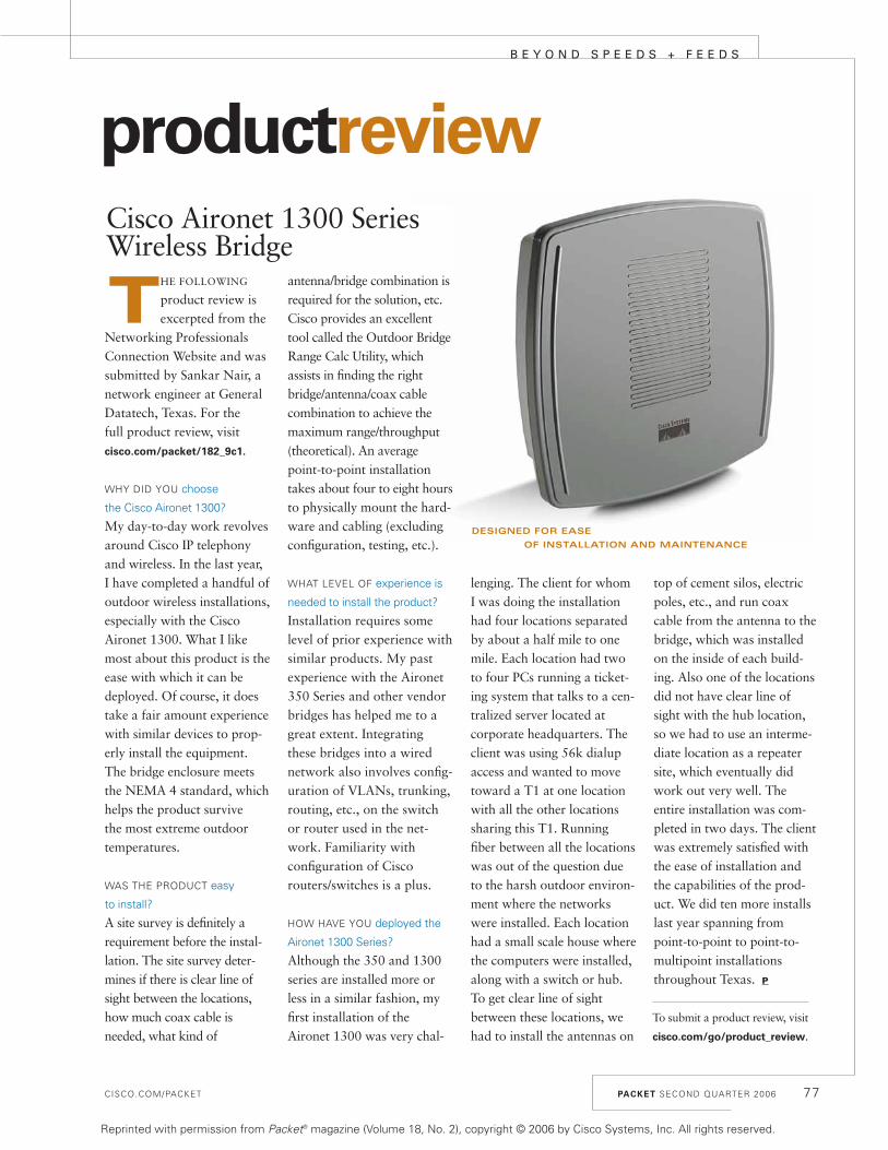
CISCO.COM/PACKET PACKET SECOND QUARTER 2006 77
B E Y O N D S P E E D S + F E E D S
productreviewCisco Aironet 1300 Series Wireless Bridge
THE FOLLOWING
product review isexcerpted from the
Networking ProfessionalsConnection Website and wassubmitted by Sankar Nair, anetwork engineer at GeneralDatatech, Texas. For the full product review, visitcisco.com/packet/182_9c1.
WHY DID YOU choose
the Cisco Aironet 1300?
My day-to-day work revolvesaround Cisco IP telephonyand wireless. In the last year,I have completed a handful ofoutdoor wireless installations,especially with the CiscoAironet 1300. What I likemost about this product is theease with which it can bedeployed. Of course, it doestake a fair amount experiencewith similar devices to prop-erly install the equipment.The bridge enclosure meetsthe NEMA 4 standard, whichhelps the product survive the most extreme outdoortemperatures.
WAS THE PRODUCT easy
to install?
A site survey is definitely arequirement before the instal-lation. The site survey deter-mines if there is clear line ofsight between the locations,how much coax cable isneeded, what kind of
antenna/bridge combination isrequired for the solution, etc.Cisco provides an excellenttool called the Outdoor BridgeRange Calc Utility, whichassists in finding the rightbridge/antenna/coax cablecombination to achieve themaximum range/throughput(theoretical). An averagepoint-to-point installationtakes about four to eight hoursto physically mount the hard-ware and cabling (excludingconfiguration, testing, etc.).
WHAT LEVEL OF experience is
needed to install the product?
Installation requires somelevel of prior experience withsimilar products. My pastexperience with the Aironet350 Series and other vendorbridges has helped me to agreat extent. Integratingthese bridges into a wirednetwork also involves config-uration of VLANs, trunking,routing, etc., on the switchor router used in the net-work. Familiarity with configuration of Ciscorouters/switches is a plus.
HOW HAVE YOU deployed the
Aironet 1300 Series?
Although the 350 and 1300series are installed more orless in a similar fashion, myfirst installation of theAironet 1300 was very chal-
lenging. The client for whomI was doing the installationhad four locations separatedby about a half mile to onemile. Each location had twoto four PCs running a ticket-ing system that talks to a cen-tralized server located atcorporate headquarters. Theclient was using 56k dialupaccess and wanted to movetoward a T1 at one locationwith all the other locationssharing this T1. Runningfiber between all the locationswas out of the question dueto the harsh outdoor environ-ment where the networkswere installed. Each locationhad a small scale house wherethe computers were installed,along with a switch or hub.To get clear line of sightbetween these locations, wehad to install the antennas on
top of cement silos, electricpoles, etc., and run coaxcable from the antenna to thebridge, which was installedon the inside of each build-ing. Also one of the locationsdid not have clear line ofsight with the hub location,so we had to use an interme-diate location as a repeatersite, which eventually didwork out very well. Theentire installation was com-pleted in two days. The clientwas extremely satisfied withthe ease of installation andthe capabilities of the prod-uct. We did ten more installslast year spanning frompoint-to-point to point-to-multipoint installationsthroughout Texas. P
DESIGNED FOR EASE
OF INSTALLATION AND MAINTENANCE
To submit a product review, visit
cisco.com/go/product_review.
Reprinted with permission from Packet® magazine (Volume 18, No. 2), copyright © 2006 by Cisco Systems, Inc. All rights reserved.

CISCO.COM/PACKET PACKET SECOND QUARTER 2006 79
N E T P R O E X P E R T
netproexpert
The Networking Professionals Connection isan online community for Cisco expertsand networking colleagues. Following are
excerpts from a recent Ask the Expert forum,“Configuring and Troubleshooting ASA 5500 andPIX 7.0,” moderated by Cisco’s Mynul Hoda. Toview the full discussion, visit cisco.com/packet/182_
10a1. To join other live online discussions, visitcisco.com/discuss/networking.
WHY IS IT NECESSARY to assign the PIX a management
IP address in Transparent mode, without which it
doesn’t allow inside hosts to ping outside hosts? What
is the significance of the IP address to the PIX in
Transparent mode?
To understand the need for assigning IP addressesfrom the same subnet as the inside and outside inter-face, it is important to understand how the ASAworks when configured for Transparent mode. Inthis mode, the ASA operates at Layer 2; therefore,the routing table is not examined to find out the out-going interface for the traffic going through the ASA.Just like the switch, ASA needs to build the MACtable (CAM table) to forward the packet to theappropriate interface. However, the way the MAC isdiscovered on the ASA is very different than on theswitch. When the ASA receives a packet and if thedestination MAC is not in the Layer 2 forwardingtable, then ASA doesn’t flood the packet out bothinterfaces like the switch does, as that would be asecurity risk. Rather, it will send either an AddressResolution Protocol (ARP) or Internet Control Mes-sage Protocol (ICMP) message out both interfaces,trying to determine which interface the destinationMAC address resides. ARP is used when destinationhost is on the same local segment, but ICMP is usedif not in the same segment. In both cases, a sourceaddress is used and that address is the managementinterface IP address. If you do not assign this IPaddress, then ASA will not learn the MAC addressand will not be able to pass any traffic.
DOES THE ASA forward the broadcast to the outside?
How does the outside interface learn the MAC address
and the IP address of the inside host?
No, it doesn’t, except the ARP broadcast betweenthe inside and outside host. When the outside hostsends the ARP broadcast, ASA will receive it andbuild up its MAC table. The ASA will make the ARPrequest on behalf of the outside host based on thedestination IP address. Once the host inside repliesback, the ASA would know about the inside hostMAC address. If the destination IP is not in the samesubnet, the discovery of the MAC will take placeusing the ping packets. To make the ARP request orwhen sending ping packets, the ASA is required tohave the IP address, as both types of packet will usemanagement interface IP as the source, which is thereason you need this IP. Refer to cisco.com/packet/
182_10a2 for packet flow through Transparent FW.
WHEN DOING A cable-based failover and using a
dedicated interface for stateful failover between two
PIX firewalls, do the firewalls also monitor the stateful
interface for failover purposes along with the other
interfaces? Can I use a crossover to connect the
stateful failover interfaces together?
Yes, the PIX boxes monitor the stateful failoverinterface too. And yes, you can use a crossover cablefor the stateful link. The PIX documentation recom-mends this method. P
Configuring and TroubleshootingCisco ASA 5500 and PIX 7.0
PACKET SECOND QUARTER 2006 79
GOT A QUESTION?Expert Mynul Hoda will answer your
questions about configuring and troubleshooting Cisco ASA 5500 and PIX 7.0 in a live
discussion forum June 5 through June 30, 2006. Join your networking peers!
cisco.com/go/askeexpert/packet
MYNUL HODA is a lead engineer in the High Touch
Technical Support group at Cisco.
Reprinted with permission from Packet® magazine (Volume 18, No. 2), copyright © 2006 by Cisco Systems, Inc. All rights reserved.

CISCO.COM/PACKET
environment is simplified hybrid routing. This option also usescoverage zones, but clients send requests directly to the CDMor content router. The CDM or content router then redirectsclient requests to the most appropriate WAE using HTTP redi-rection, based on coverage zones that you configure.
Splitting Live and Rebroadcast Streams
WAES ALSO OFFER stream-splitting services to clientsrequesting live and scheduled rebroadcast streams. With
stream splitting, a WAE receives an incoming stream and fans itout to requesting clients (Figure 2, page 27). WAEs treatrebroadcast streams that you schedule on your streamingservers no differently than live streams.
With live splitting, the live stream always orig-inates from the origin server as a single stream tothe incoming interface of the WAE. Both front-and back-end streams can be either multicast orunicast.
With unicast-to-unicast delivery, the WAEreceives the live or rebroadcast stream as unicastand splits it to clients as individual unicaststreams. Each client receives a distinct streamcausing potential duplicates on the network,depending on client location. For example, if tworequesting clients are on the same subnet, twoduplicate streams will flow to that subnet over thenetwork.
Alternatively, in a unicast-to-multicast configu-ration, the WAE generates a multicast streamfrom the unicast input and sends it to a multicastgroup that you can configure on the WAE. Pro-vided that you enable multicast on the down-stream network, the routers will forward themulticast group traffic to its members withoutduplication. This delivery mechanism is known aspull-splitting, because client requests trigger theWAE to proactively “pull” the unicast streamfrom the origin server.
You can also configure multicast-to-multicastsplitting. This is beneficial because you can con-duct services in the WAE, such as content authen-tication, URL filtering, and Internet ContentAdaptation Protocol (server offload) services.Finally, multicast-to-unicast splitting lets you dis-tribute your streams to clients in areas of yournetwork that do not support multicast.
These last two methods are known as push-
splitting because the origin server blindly“pushes” the stream to the network for the WAEto receive by joining the multicast group.
When deploying streamingmedia, using suite of perform-ance-acceleration tools helps thequality of audio-video broadcastsremain consistent and reliable.The Cisco ANS architectureincludes Cisco ACNS software forautomating content replication toWAEs in multiple sites where thecontent is locally cached andclient requests are served. Furtherconserving bandwidth, live streamsplitting allows the origin server toavoid replicating the stream for each receiving client. P
PACKET SECOND QUARTER 2006 81
• Cisco Application
Networking Services/
Application Acceleration
cisco.com/packet/182_5a1
• Content Networking
Fundamentals, by Silvano
Da Ros (Cisco Press,
ISBN: 1587052407)
cisco.com/packet/182_5a2
Further Reading
Streaming Media, Continued from page 27
PACKET ADVERTISER INDEX
ADVERTISER URL PAGE
ADTRAN www.adtran.com/info/wanemulation 2
Aladdin Knowledge Systems www.Aladdin.com/Cisco IFC
Boson Software www.boson.com/p16 A
Cisco Press www.ciscopress.com B
Cisco Marketplace www.cisco.com/go/marketplace/packet 58
Cisco Systems Networkers www.cisco.com/go/nwo6 35
Cisco Systems www.cisco.com/poweredby 13/41
Citrix www.citrix.com/cisco 78
Colt www.colt.net D
eIQnetworks www.eiqnetworks.com/cisco 10
Empirix www.empirix.com/ipcc 80
Energis www.energis.com 24
GL Communications www.gl.com 18
Global Knowledge www.globalknowledge.com/deliver 28
Hong Kong Broadband Network www.hkbn.net 70
IPcelerate www.ipcelerate.com 30 / 44
NetQoS www.netqos.com OBC
NetScout www.netscout.com 54
Network General www.networkgeneral.com/cisco2 14
OPNET Technologies www.opnet.com 66
Panduit www.panduit.com/cp01 IBC
Solsoft www.solsoft.com/packet2 76
Spanlink Communications www.spanlink.com 6
Spirent Communications www.spirent.com/go/securitytest 62
Sprint www.sprint.com/business F
Statseeker www.statseeker.com 32
Trend Micro www.trendmicro.com/cisco 52 / 53
Websense www.websense.com/security 20
Reprinted with permission from Packet® magazine (Volume 18, No. 2), copyright © 2006 by Cisco Systems, Inc. All rights reserved.

PERSONAL RELATIONSHIPS
EXPAND ON
THE WEB
The Internet allows people to build social networks thatsupport personal decisions,
according to findings in a reportpublished by Pew Internet &
American Life Project. Refutingprevious assumptions that
the Web limits social interaction, the report statesthat technologies such as the
Internet, e-mail, instant messaging, and cell phones
allow people to develop both “core ties” (social
contacts involving a very closerelationship with a person) and
“significant ties” (people somewhat closely connected toan individual) at a more global
level. Study respondentsreported an average 23 coreties and 27 significant ties.
The report is based on the find-ings of two daily tracking
surveys on Americans’ use ofthe Internet, and involved
interviews with 2,200 adults age18 and older. [clickz.com]
Level: CCNAIP RoutesAnswersQUESTIONS ON PAGE 16.
1. Enter the ip route destination-network [mask]
{next-hop-address | outbound-interface} [distance]
[permanent] global command. Example: RouterB
(config) #ip route 172.17.0.0 255.255.0.0 172.16.0.1
2. The rule of split horizon is that it is never useful to
send information about a route back in the direction
from which the original update came.
3. AD is an integer from 0 to 255 that rates the trustwor-
thiness of routing information received from a neigh-
boring router. The AD is used as the tie-breaker
when a router has multiple paths from different rout-
ing protocols to the same destination. The lower the
path’s AD, the more likely it is to be used.
4. By periodically broadcasting the entire routing table
out all active interfaces. This method is often called
“routing by rumor.”
5. Convergence is when all routers have consistent
knowledge and correct routing tables.
Source: CCNA Flash Cards and Exam Practice Pack
cachefile
PACKET SECOND QUARTER 2006 CISCO.COM/PACKET
S N I P P E T S O F W I S D O M F R O M O U T O N T H E N E T
82
Using Fingerprints to Secure NetworksUniversity of Buffalo, New York, research findings could help eliminate the need to remembera dizzying array of passwords, or aid forensicsspecialists, according to Venu Govindaraju, professor of computer science and engineering,and director of the school’s Center for UnifiedBiometrics and Sensors. Govindaraju and histeam have determined the minimum surfacearea required for fingerprint scanning to achievea level of security that is roughly comparable to the security achieved with a six-letter password. The algorithmtakes into account the factthat even a legitimate fingerprint doesn’t alwayslook the same due to theway a person presses on a pad or because of moisture or other factors.[networkworld.com]
Cyb
er Q
uote
“To
suc
ceed
as
a te
am is
to h
old
all o
f the
mem
bers
acc
ount
able
for
thei
r ex
pert
ise.
” •
Mitc
hell
Cap
lan,
CEO
, E*T
rade
Net LingoIdentity chaos—
When a user has multiple
identities and passwords across a variety of networks,
applications, computers and/or
computing devices.[whatis.com]
the 5thwave“Think of our
relationship as aversion of Red HatLinux—I will notshare a directory
on the love-branchof your life.”
©The 5th Wavewww.the5thwave.com
NEXT-GENERATIONVOIP GEAR
HITS NEW HIGH IN 2005
The next-generation voice-over-IP equipment market
hit a new high in 2005 withUS$2.5 billion in revenue,according to Infonetics
Research. This was double thenext-generation voice
equipment revenue from theprior year. Sales are
projected to increase by 145percent over the next
four years to reach US$6.2 billion by 2009.
[networkingpipeline.com]
P O P Q U I Z
Reprinted with permission from Packet® magazine (Volume 18, No. 2), copyright © 2006 by Cisco Systems, Inc. All rights reserved.