cisco plug and play application solutions guide · figure 10 cisco cics option to order isr’s...
TRANSCRIPT

Cisco Plug and Play Application Solutions Guide 1
Cisco Plug and Play Application Solutions Guide

Cisco Plug and Play Application Solutions Guide 2
Table of Contents About this Guide ........................................................................................................................................... 4
Purpose ..................................................................................................................................................... 4
Intended Audience .................................................................................................................................... 4
Challenges ..................................................................................................................................................... 4
The Cisco Plug and Play Solution .................................................................................................................. 5
Components .............................................................................................................................................. 5
Deploying Cisco Plug and Play Deployment on Cisco ISRs ............................................................................ 5
Cisco Plug and Play Deployment Overview .................................................................................................. 6
Installing the Cisco Plug and Play Server Components ................................................................................. 7
Installing and Setting Up the Cisco Prime Infrastructure .......................................................................... 7
Installing and Setting Up the Cisco Plug and Play Gateway ...................................................................... 8
Pre-provisioning Tasks ................................................................................................................................ 10
Defining Day 0 Bootstrap Configuration ................................................................................................. 10
Defining Day 1 Configuration Template .................................................................................................. 14
Importing the IOS Image File (Optional) ................................................................................................. 14
Defining the Cisco Plug and Play Deployment Profile............................................................................. 15
Deploying the Cisco Plug and Play Profile ............................................................................................... 16
Bootstrapping and Registering the ISR ....................................................................................................... 19
Bootstrapping from Cisco Prime Infrastructure ...................................................................................... 19
Exporting ............................................................................................................................................. 20
Delivering through TFTP ...................................................................................................................... 20
E-mailing the Bootstrap Configuration ............................................................................................... 21
E-mailing the PIN ................................................................................................................................. 21
Bootstrap Using Cisco Integrated Customization Services (CICS) ........................................................... 24
Bootstrap Using USB Flash (Manual Option) .......................................................................................... 26
Bootstrap Using Auto Install ................................................................................................................... 27
Bootstrap Using Cisco Configuration Professional Express (CCP Express) .............................................. 29
Bootstrap Using Smart Install ................................................................................................................. 29
Cisco Plug and Play Applications ................................................................................................................. 29
Bootstrap Flow Using Cisco Plug and Play Application ........................................................................... 32
Troubleshooting Information ...................................................................................................................... 42
Cisco Plug and Play Application Solutions Guide 3
Recommended Versions ......................................................................................................................... 42
Installation and Setup Issues .................................................................................................................. 42
Connectivity Issues .................................................................................................................................. 43
Checking the Status of the Servers ......................................................................................................... 44
Collecting Logs ........................................................................................................................................ 45
Cisco Routers/Switches with Cisco CNS Agent ....................................................................................... 51
Redeploying the Already Deployed Devices ........................................................................................... 52
References .................................................................................................................................................. 52
List of Figures Figure 1 Cisco Plug and Play Deployment of ISR at the Branch .................................................................... 7 Figure 2 Sample Template “acme-branch-day0-bootstrap”, an instance of pre-defined Cisco Plug and Play Bootstrap template ............................................................................................................................. 12 Figure 3 Sample Cisco Plug and Play Deployment Profile with bootstrap and configuration template .... 16 Figure 4 Properties of the Bootstrap configuration template .................................................................... 17 Figure 5 Adding a device and it’s parameters for pre-previsioning ............................................................ 19 Figure 6 Bootstrap Delivery Options ........................................................................................................... 20 Figure 7 Downloading Bootstrap Configuration from Cisco Plug and Play Gateway ................................. 22 Figure 8 Viewing the status of Cisco Plug and Play Deployment in Cisco Prime Infrastructure ................ 23 Figure 9 Viewing Detailed Status Messages ............................................................................................... 24 Figure 10 Cisco CICS option to order ISR’s with bootstrap configuration .................................................. 25 Figure 11 CICS-based Preprovisioning Steps ............................................................................................... 26 Figure 12 USB based Provisioning ............................................................................................................... 27 Figure 13 Bootstrap using AutoInstall ......................................................................................................... 28 Figure 14 Cisco Plug and Play Settings ........................................................................................................ 29 Figure 15 Cisco Plug and Play Application based provisioning ................................................................... 30 Figure 16 Redpark Console Cable (c2-RJ45V) ............................................................................................. 31 Figure 17 Sample USB type A to mini USB type B cable ............................................................................. 31 Figure 18 Sample USB to Serial adapter ..................................................................................................... 32 Figure 19 Cisco Plug and Play Application Launch Page ............................................................................. 34 Figure 20 Cisco Plug and Play Application Settings Page ............................................................................ 35 Figure 21 Specify the PIN in Cisco Plug and Play Application ..................................................................... 37 Figure 22 Deployment Status of the Cisco Plug and Play Application ........................................................ 39 Figure 23 Cisco Plug and Play Application - Starting device deployment from “Downloads” page ........... 41 Figure 24 Cisco Plug and Play Application – Emailing Support Logs ........................................................... 46 Figure 25 Monitoring Deployment Status on the Cisco Plug and Play Application .................................... 50

Cisco Plug and Play Application Solutions Guide 4
About this Guide
Purpose This document provides the business need and benefits of the Cisco Plug and Play Deployment Solution, and provides detailed information about the solution components, deployment scenarios, implementation, and configuration procedures for the solution.
Intended Audience This guide is for technical personnel involved in the specification, design, and implementation of specific Plug and Play based network deployment solutions. It includes the following roles:
• Network Administrators • Cisco Account teams • Cisco SEs • Cisco Technical Marketing Engineers (TMEs)
Challenges Enterprises incur major costs to install and deploy the large number of devices that go into their data center and branch networks. Typically, every device has to be pre-staged by a skilled installer and loaded, through a console connection, with a CLI configuration that allows it to connect to the rest of the network. This process is costly, time consuming, and error-prone.
The current methods of deploying networks that customers use involve a great deal of coordination between organizations and many manual steps, thus making it expensive, time consuming and error-prone. As companies look at reducing operating expenses, the ease of network deployment and ongoing changes becomes a key factor in their purchasing decisions. The ability to provide a scalable, easy to use, secure and common solution across Cisco equipment to simplify deployments is a differentiator in the purchase decision and an enabler to the adoption of more advanced Cisco technologies and services. Additionally, as customers purchase and deploy Cisco’s Borderless Network solutions and systems they will demand that each component not require a completely different deployment methodology. This is clear from our interactions with the customers that they are already asking for a common methodology that spans across the Cisco devices they deploy in their sites. Today, in order to “bring-up” a new site, most customers follow these processes: • Send the Cisco equipment to the staging facility • Unpack the router, switches, access points etc. using skilled, IOS savvy technicians. • Load the correct image, configuration files, and any other required start-up files • Repack the equipment • Reship the equipment • Unpack the equipment at the site • Rack, stack, and cable the equipment
Cisco Plug and Play Application Solutions Guide 5
• Finally, turn the site over to the NOC. And if Customers don’t stage the equipment themselves, then they pay a 3rd-party to stage the equipment or they send the IOS savvy technicians to the site. Both these options are very expensive.
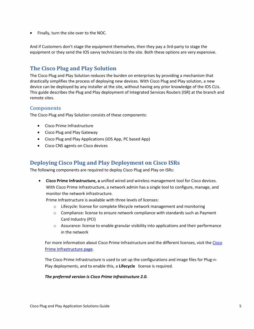
The Cisco Plug and Play Solution The Cisco Plug and Play Solution reduces the burden on enterprises by providing a mechanism that drastically simplifies the process of deploying new devices. With Cisco Plug and Play solution, a new device can be deployed by any installer at the site, without having any prior knowledge of the IOS CLIs. This guide describes the Plug and Play deployment of Integrated Services Routers (ISR) at the branch and remote sites.
Components The Cisco Plug and Play Solution consists of these components:
• Cisco Prime Infrastructure • Cisco Plug and Play Gateway • Cisco Plug and Play Applications (iOS App, PC based App) • Cisco CNS agents on Cisco devices
Deploying Cisco Plug and Play Deployment on Cisco ISRs The following components are required to deploy Cisco Plug and Play on ISRs:
• Cisco Prime Infrastructure, a unified wired and wireless management tool for Cisco devices. With Cisco Prime Infrastructure, a network admin has a single tool to configure, manage, and monitor the network infrastructure. Prime Infrastructure is available with three levels of licenses:
o Lifecycle: license for complete lifecycle network management and monitoring o Compliance: license to ensure network compliance with standards such as Payment
Card Industry (PCI) o Assurance: license to enable granular visibility into applications and their performance
in the network
For more information about Cisco Prime Infrastructure and the different licenses, visit the Cisco Prime Infrastructure page.
The Cisco Prime Infrastructure is used to set up the configurations and image files for Plug-n-Play deployments, and to enable this, a Lifecycle license is required.
The preferred version is Cisco Prime Infrastructure 2.0.
Cisco Plug and Play Application Solutions Guide 6
• Cisco Plug and Play Gateway is part of the Cisco Prime Infrastructure offering. It can function in the Demilitarized Zone (DMZ), hosts the Plug and Play deployment jobs from Cisco Prime Infrastructure, and accepts connections from new devices (e.g. ISR) coming on the network
• Plug and Play Applications are standalone applications (IPhone/IPad and PC) that help in deploying ISRs with bootstrap configurations and to trigger Plug and Play deployments. These applications work with Cisco Prime Infrastructure version 1.3 and higher.
• Cisco CNS Agent is the embedded IOS agent that must be running on Cisco devices.
Cisco Plug and Play Deployment Overview In order to deploy an ISR branch WAN router using Cisco Plug and Play, execute the following steps:
1. Install and set up the Cisco Plug and Play Server components. 2. Based on the version of the Cisco Prime Infrastructure and the deployment requirement, you
may need to install and set up the Cisco Plug and Play Gateway (see the table below for information on installation)
3. Design a Plug and Play Profile on Cisco Prime Infrastructure 4. Add and pre-provision the ISR in Cisco Prime Infrastructure 5. Bootstrap and register the ISR with the Cisco Prime Infrastructure 6. Optionally, manage this device via Cisco Prime Infrastructure for Day2 onwards management.
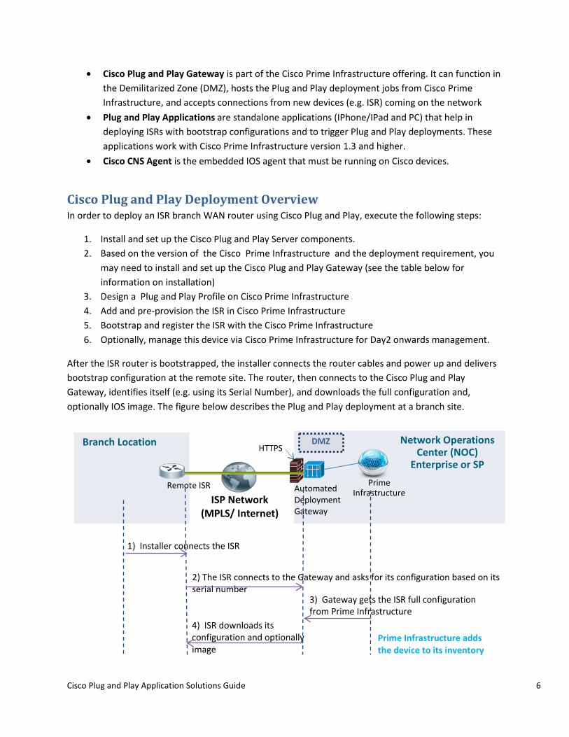
After the ISR router is bootstrapped, the installer connects the router cables and power up and delivers bootstrap configuration at the remote site. The router, then connects to the Cisco Plug and Play Gateway, identifies itself (e.g. using its Serial Number), and downloads the full configuration and, optionally IOS image. The figure below describes the Plug and Play deployment at a branch site.
4) ISR downloads its configuration and optionally image
Remote ISR
Branch Location Network Operations Center (NOC)
Enterprise or SP Prime
Infrastructure ISP Network
(MPLS/ Internet)
HTTPS
2) The ISR connects to the Gateway and asks for its configuration based on its serial number
1) Installer connects the ISR
3) Gateway gets the ISR full configuration from Prime Infrastructure
Automated Deployment Gateway
DMZ
Prime Infrastructure adds the device to its inventory

Cisco Plug and Play Application Solutions Guide 7
Figure 1 Cisco Plug and Play Deployment of ISR at the Branch
Installing the Cisco Plug and Play Server Components Cisco Prime Infrastructure 2.0 provides integrated Plug and Play Solution in a single box. No separate installation of Cisco Plug and Play Gateway is required for non-DMZ deployment. The installation of Cisco Plug and Play Gateway in DMZ deployment is also made simpler compared to the earlier versions (Cisco Prime Infrastructure 1.2).
Use the following table to identify the required installation steps, and then follow the sections in this document to install the server side components.
Network Deployment
Prime Infrastructure Version
Install Action
Non DMZ PI 2.0 and higher Note: Prime Infrastructure installation includes Plug and Play Gateway
Please follow the Install and Setup Prime Infrastructure section. (No separate Plug and Play Gateway installation is required)
Non DMZ PI 1.2 Note: Separate installation of Prime Server and Plug and Play Gateway is required
1. Please follow Install and Setup Prime Infrastructure Server section
2. Please follow Install and Setup Plug and Play Gateway section
DMZ PI 2.0 and higher Note: Separate installation of Prime Server and Plug and Play Gateway is required for this deployment
1. Please follow Install and Setup Prime Infrastructure Server section
2. Please follow Install and Setup Plug and Play Gateway section
DMZ PI 1.2
Note: Separate installation of Prime Server and Plug and Play Gateway is required for this deployment
1. Please follow Install and Setup Prime Infrastructure section
2. Please follow Install and Setup Plug and Play Gateway section
Installing and Setting Up the Cisco Prime Infrastructure The Cisco Plug and Play Gateway is integrated in the Cisco Prime Infrastructure 2.0. The Cisco Prime Infrastructure server installation includes the installation of Cisco Plug and Play gateway as well. It is recommended to use Prime Infrastructure 2.0 for the Cisco Plug and Play Solution.
Please follow the steps documented in the Cisco Prime Infrastructure Quick Start Guide to install Prime Infrastructure 2.0 on your network.

Cisco Plug and Play Application Solutions Guide 8
Installing and Setting Up the Cisco Plug and Play Gateway NOTE: You must install the Cisco Prime Infrastructure Server before installing the Cisco Plug and Play Gateway Server.
After Cisco Prime Infrastructure server is installed, and is up and running, Cisco Plug and Play Gateway can then be installed on a separate virtual machine or an appliance. This step is only required for DMZ deployment scenario or when earlier release of Cisco Prime Infrastructure version 1.2 or 1.3 is used.
In order to listen to connections that are being deployed from the ISRs, and to host the Cisco Plug and Play deployment jobs, the Cisco Plug and Play Gateway must be installed in the DMZ. The communication between the Cisco Plug and Play Gateway and the Cisco Prime Infrastructure server must also be set up. Cisco Prime Infrastructure adds jobs (for the new devices) to the Cisco Plug and Play Gateway; the Gateway contacts Prime Infrastructure to deliver the configuration for a device that’s performing the Cisco Plug and Play deployment.
No separate installation of Cisco Plug and Play Gateway is required for non-DMZ deployment with Cisco Prime Infrastructure 2.0.
Please follow steps documented in Chapter 9 of the Cisco Prime Infrastructure Quick Start Guide to install and set up the Cisco Plug and Play Gateway in your network.
Sample output of “pnp setup” CLI command with Cisco Plug and Play Gateway 2.0
Step 1 Log in to the Cisco Plug and Play Gateway using the administrative username and password.
Step 2 In the command prompt, enter the pnp setup command and press Enter.
Step 3 The console prompts for the following parameters: – Prime Infrastructure server IP address. – Use Self-Signed Server Certificate – Automatically download Prime Infra Server Certificate – Number of Event Gateways to start with plaintext and crypto operations – CNS Event command that specify how managed devices will connect to this
gateway – Commit changes – Prime Infra admin username and password for downloading Prime Server
Certificate
Step 4 The console outputs the following:

Cisco Plug and Play Application Solutions Guide 9
bgl-pnp-dev1-ovf/admin# pnp setup ###################################################################### Enter Plug and Play Gateway Setup (setup log /var/KickStart/install/setup.log) For detail information about the parameters in this setup, refer to Plug and Play Gateway Admin Guide. ###################################################################### Enter Prime Infrastructure IP Address: [] primeserver.acme.com Enable self certificate for server bgl-pnp-dev1-ovf (y/n) [y] Self Signed Certificate already available do you want to recreate (y/n)? [n] y Generated Self Signed Certificate for 5 Years (1825 Days) Automatic download of SSL Certificate is possible if Prime Infrastructure Server is up and running. Automatically download the certificate for server primedev-01.cisco.com (y/n) [n] y Enter number of Event Gateways that will be started with crypto operation: [5] Enter number of Event Gateways that will be started with plaintext operation: [5] The CNS Event command configures how the managed devices should connect to this particular Plug and Play Gateway. The command entered in the following line should match what's configured on the devices WITHOUT the port number and keyword 'encrypt' if cryptographic is enabled. For example, if the following CLI is configured on devices "cns event bgl-pnp-dev1-ovf encrypt 11012 keepalive 120 2 reconnect 10", then `encrypt 11012` should be removed and the below line should be entered : "cns event bgl-pnp-dev1-ovf keepalive 120 2 reconnect 10" Another example, if this is a backup Plug and Play Gateway and the following CLI is configured on devices "cns event bgl-pnp-dev1-ovf 11011 source Vlan1 backup", then `11011` should be removed and the below line should be entered : "cns event bgl-pnp-dev1-ovf source Vlan1 backup" Unable to enter a correct CLI could cause the managed devices not be able to connect to this Plug and Play Gateway. For details, please refer to Installation and Configuration Guide. Enter CNS Event command: [cns event bgl-pnp-dev1-ovf keepalive 120 2 reconnect 10] Commit changes (y/n): y Attempting to disable the local Plug and Play Gateway in Prime Infrastructure Machine primeserver.acme.com

Cisco Plug and Play Application Solutions Guide 10
Enter the username to login to the Prime Infrastructure Machine: [admin] Enter the password to login to the Prime Infrastructure Machine: Setup is in progress....... Stop Plug and Play Gateway server Done. Plug and Play Gateway setup completed Start Plug and Play Gateway server.... Done. Plug and Play Gateway server started!
Cisco Play and Play Gateway is now installed, set up, and running successfully.
Note: Cisco Prime Infrastructure Server Certificate installation on the Plug and Play Gateway is automated with version 2.0 setup process.
Pre-provisioning Tasks The following pre-provisioning tasks must be done for the Cisco Plug and Play devices:
• Define Day 0 bootstrap configuration using pre-canned system template “Plug and Play Bootstrap” in Cisco Prime Infrastructure.
• Define Day 1 Configuration template using CLI template, UI based template, or Composite templates in Cisco Prime Infrastructure.
• Optionally, add an image that is to be updated for Cisco Plug and Play device using the “Software Image Management” feature in Cisco Prime Infrastructure.
• Create “Plug and Play Profile”, and add the Day 0 bootstrap configuration template (specified above), Day 1 configuration template, and an optional image to be applied.
• Publish the newly created Cisco Plug and Play Profile. • Deploy the newly created Cisco Plug and Play Profile. • During the Deploy process, add a Cisco Plug and Play device to the profile, and optionally
register its serial number. If you don’t specify a Cisco device Serial number, Cisco Plug and Play Solution will automatically discover it and add it to the profile during the deployment process.
• As soon as the deployment is triggered by the device calling home, the status of the deployment can be checked back in Cisco Prime Infrastructure from the “Plug and Play Status” screen. Upon successful deployment, the status will indicate success, and the device serial number is registered and displayed back in the Cisco Prime Infrastructure. The device is now added in the Cisco Prime Infrastructure Inventory, and can be used for day-to-day device management.
Defining Day 0 Bootstrap Configuration Network administrators can use a configuration template on Cisco Prime Infrastructure to define the bootstrap configuration that ISR needs in order to contact the Cisco Plug and Play Gateway. This bootstrap configuration can be sent to the installer via email, and loaded on the router through a Console, or can be downloaded by the installer directly from the Cisco Prime Infrastructure. The bootstrap configuration template on Cisco Prime Infrastructure will configure the Cisco Networking

Cisco Plug and Play Application Solutions Guide 11
Services (CNS) agent on the ISR. The CNS agent is used to establish the connection from the ISR to the Cisco Plug and Play Gateway. In addition, the bootstrap template can optionally contain the configuration for the WAN interface of the ISR; if the WAN is not already configured at the remote site (e.g. the remote site doesn’t use DHCP at the WAN).
Cisco Prime Infrastructure 2.0 has a pre-defined system template for Cisco Plug and Play day 0 bootstrap configurations. The administrator can use this template to create an instance of the bootstrap configuration template.
The following procedure details steps to create an instance of a pre-defined Cisco Plug and Play bootstrap template in Cisco Prime Infrastructure.
Step 1 Select Feature > Design
Step 2 From the left menu, expand CLI Templates tree Node.
Step 3 Select CLI Template > System Templates – CLI.
Step 4 Select “Plug and Play Bootstrap” template.
Step 5 Give this template a name. eg: acme-branch-bootstrap.
Step 6 (Optional) Select device types where this template is applicable.
Step 7 (Optional) Edit any values shown in the template as required. Values shown are default.
Step 8 Click Save as New Template.
It should be displayed under My Templates node with the name given to it.
Figure 2 shows the pre-defined Cisco Plug and Play Bootstrap System template.

Cisco Plug and Play Application Solutions Guide 12
Figure 2 Sample Template “acme-branch-day0-bootstrap”, an instance of pre-defined Cisco Plug and Play Bootstrap template

Cisco Plug and Play Application Solutions Guide 13
The following is a sample of the ISR CNS bootstrap configuration that identifies the ISR by its Serial Number (Gateway refers to the Cisco Plug and Play Gateway). All fields in bold should be replaced by the corresponding values in your network:
ip host <Gateway FQDN> <Gateway IP address> ip host <Gateway hostname> <Gateway IP address> cns trusted-server all-agents <Gateway FQDN> cns trusted-server all-agents <Gateway hostname> cns trusted-server all-agents <Gateway IP address> cns id hardware-serial cns id hardware-serial event cns id hardware-serial image cns event <Gateway FQDN> 11011 keepalive 120 2 reconnect-time 60 cns exec 80 cns image server http://<Gateway FQDN>/cns/HttpMsgDispatcher status http://<Gateway FQDN>/cns/HttpMsgDispatcher cns config partial <Gateway FQDN> 80 cns config initial <Gateway FQDN> 80
Another option is to identify all ISRs of the same device type using the Unique Device Identifier (UDI). This option should be used only if all these ISRs have the same configuration and image. Due to the granularity and inherent security that the ISRs provide, it is strongly recommended to identify an ISR by its Serial number (ID).

Cisco Plug and Play Application Solutions Guide 14
The following is a sample of the ISR CNS bootstrap configuration that identifies the ISR by its device type (Gateway refers to the Cisco Plug and Play Gateway). All fields in bold should be replaced by the corresponding values in your network
ip host <Gateway FQDN> <Gateway IP address> ip host <Gateway hostname> <Gateway IP address> cns trusted-server all-agents <Gateway FQDN> cns trusted-server all-agents <Gateway hostname> cns trusted-server all-agents <Gateway IP address> cns id udi cns id udi event cns id udi image cns event <Gateway FQDN> 11011 keepalive 120 2 reconnect-time 60 cns exec 80 cns image server http://<Gateway FQDN>/cns/HttpMsgDispatcher status http://<Gateway FQDN>/cns/HttpMsgDispatcher cns config partial <Gateway FQDN> 80 cns config initial <Gateway FQDN> 80 inventory
Note: Cisco Plug and Play Applications do not support UDI or type-based deployment yet. Hence, they cannot be used. UDI support by underlying CNS embedded agent is not available on all ISR platforms and may have some issues.
For more information about the different ISR bootstrapping options, refer to the Bootstrap and Register the ISR section of this document.
Note: Cisco Prime Infrastructure version 1.3 and earlier does not have a pre-defined system template for Cisco Plug and Play bootstrap configuration. Administrator can use the above sample template and define it as a CLI template for bootstrap configuration in Cisco Prime Infrastructure.
Defining Day 1 Configuration Template During the Cisco Plug and Play deployment process, the ISR WAN router at the remote site downloads a configuration file that enables features and services on the router to connect that site to the rest of the network. This configuration file is generated using a single template or a composite template on Cisco Prime Infrastructure. For more information on how to use templates on Cisco Prime Infrastructure, refer to the “Designing the Network” section of the Cisco Prime Infrastructure User Guide.
Importing the IOS Image File (Optional) In many cases, enterprises validate a specific IOS image version for ISR routers and standardize on it. For this reason, Cisco Plug and Play deployment allows you to specify the desired IOS image version that must be running on the ISR. To use this capability, import the IOS image file into Cisco Prime Infrastructure using the Software Image Management (SWIM) steps described in the “Operating the Network” section of the Cisco Prime Infrastructure User Guide.

Cisco Plug and Play Application Solutions Guide 15
Defining the Cisco Plug and Play Deployment Profile The following procedure details steps design the Cisco Plug and Play Deployment Profile.
Step 1 Select Design > Plug and Play Profiles.
Step 2 Hover the mouse over Plug and Play Profile Quick View icon, and click New.
Step 3 Select the Device Type of the new devices that can use this profile.
Note In bulk deployments, the devices use the same deployment profile with the same set of images and configurations. To use the deployment profile for specific device IDs, do not select the Device Type.
Step 4 (Optional) Associate the bootstrap CLI template.
Step 5 (Optional) Associate a software image and specify the flash location on the device where the image needs to be distributed.
Step 6 (Optional) Associate the configuration template.
Note: One of the above must be specified (eg. Bootstrap template or Day 1 configuration template or Image file)
Step 7 (Optional) Image flash location.
Step 8 Click Save as New Plug and Play Profile. Saved profiles will appear under “Plug and Play Profile” left side tree Node.
Step 9 Click Publish to publish your profile and make it available for future deployments.

Cisco Plug and Play Application Solutions Guide 16
Figure 3 Sample Cisco Plug and Play Deployment Profile with bootstrap and configuration template
Deploying the Cisco Plug and Play Profile Now that the Cisco Plug and Play Deployment Profile is designed, it is time to add and pre-provision ISR WAN routers to prepare them for Plug and Play deployment.
Step 1 Choose Deploy > Plug and Play Deployment Profiles.
Step 2 From the Plug and Play Deployment Profiles page, select the profile, and click Deploy.
Step 3 From the Device Provisioning Profiles page, click Add to deploy a new device.
Note A single profile may have multiple provisioning definitions that can be applied for different devices.
Step 4 (Optional) Specify the hardware serial-ID or the UDI of the device.
Step 5 Specify the following profile parameters and click Apply.
Bootstrap template properties
• PnP-Gateway Hostname—Specify the hostname of the Cisco Plug and Play Gateway. For a single box installation, this will be the same as the Cisco Prime Infrastructure Server name.

Cisco Plug and Play Application Solutions Guide 17
• PnP-Gateway IP—Specify the IP address of the Cisco Plug and Play Gateway IP Address.
• Note: This IP address has to be reachable from an ISR WAN router.
• You can choose to use the default value for the rest of the parameters (default) or modify if necessary. The default device registration in Cisco Prime Infrastructure uses the Device Serial number (Hardware-Serial). This serial ID for a device can be found using the “show inventory” CLI.
Figure 4 Properties of the Bootstrap configuration template
• Image properties
• Image location—by default, the location specified during the design phase is shown as the target location. If required, you can change this location.
• Continue on Image Failure—allows you to continue with the configuration deployment, even if the image is not successfully deployed.
• Erase Flash—allows you to erase the flash memory before distributing the image (This will erase the entire content of the flash).
• Activate Image—allows you to activate the new image on the device.
• Configuration template properties
• If Day 1 Configuration template has any parameters that are needed per device during deployment, specify the values here.

Cisco Plug and Play Application Solutions Guide 18
Click “Apply” to save the template or image parameters.
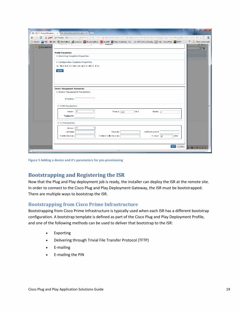
Step 6 Specify the below device management parameters to allow Cisco Prime Infrastructure to manage the router. Cisco Prime Infrastructure requires at least one of the device communication protocol (SNMP, Telnet, HTTP, SSH) to be specified for managing this device for day- to-day management.
• IP address— management IP address used for adding the device to the Cisco Prime Infrastructure device inventory.
• SNMP parameters
• SSH/Telnet parameters
Note Cisco Prime Infrastructure does not deliver any device management parameters onto the device. The device management parameters are used by Cisco Prime Infrastructure inventory to manage the device after the Cisco Plug and Play deployment is done, for managing this device in Cisco Prime Infrastructure for day-to-day management needs. All configurations are performed only through the configuration templates in the profile during Cisco Plug and Play deployment.
Step 7 Click OK.
Step 8 Click Close to close the Device Provisioning Profiles page.
At the end of this task, the device is ready on Cisco Prime Infrastructure, and a corresponding job is added to the Cisco Plug and Play Deployment Gateway, waiting for a connection from the ISR to execute.
Cisco Plug and Play Application Solutions Guide 19
Figure 5 Adding a device and it’s parameters for pre-previsioning
Bootstrapping and Registering the ISR Now that the Plug and Play deployment job is ready, the installer can deploy the ISR at the remote site. In order to connect to the Cisco Plug and Play Deployment Gateway, the ISR must be bootstrapped. There are multiple ways to bootstrap the ISR.
Bootstrapping from Cisco Prime Infrastructure Bootstrapping from Cisco Prime Infrastructure is typically used when each ISR has a different bootstrap configuration. A bootstrap template is defined as part of the Cisco Plug and Play Deployment Profile, and one of the following methods can be used to deliver that bootstrap to the ISR:
• Exporting
• Delivering through Trivial File Transfer Protocol (TFTP)
• E-mailing
• E-mailing the PIN
Cisco Plug and Play Application Solutions Guide 20
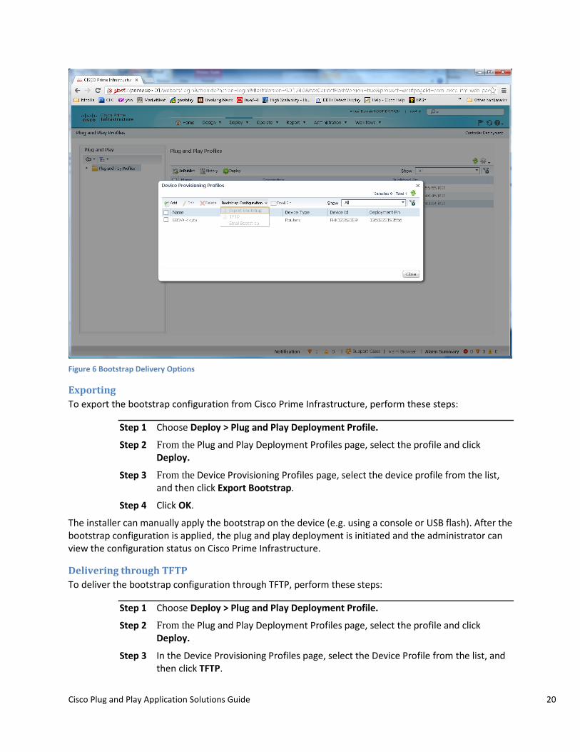
Figure 6 Bootstrap Delivery Options
Exporting To export the bootstrap configuration from Cisco Prime Infrastructure, perform these steps:
Step 1 Choose Deploy > Plug and Play Deployment Profile.
Step 2 From the Plug and Play Deployment Profiles page, select the profile and click Deploy.
Step 3 From the Device Provisioning Profiles page, select the device profile from the list, and then click Export Bootstrap.
Step 4 Click OK.
The installer can manually apply the bootstrap on the device (e.g. using a console or USB flash). After the bootstrap configuration is applied, the plug and play deployment is initiated and the administrator can view the configuration status on Cisco Prime Infrastructure.
Delivering through TFTP To deliver the bootstrap configuration through TFTP, perform these steps:
Step 1 Choose Deploy > Plug and Play Deployment Profile.
Step 2 From the Plug and Play Deployment Profiles page, select the profile and click Deploy.
Step 3 In the Device Provisioning Profiles page, select the Device Profile from the list, and then click TFTP.

Cisco Plug and Play Application Solutions Guide 21
Step 4 Click OK.
Note The TFTP can be used to deliver the bootstrap configuration. Cisco Prime Infrastructure can act as TFTP server. You can specify the file name that should be created on the TFTP server. This file is used by the auto-install enabled devices that get the IP address and TFTP server details through DHCP. In the DHCP server, the TFTP server must be configured as the Cisco Prime Infrastructure TFTP server.
E-mailing the Bootstrap Configuration To e-mail the bootstrap configuration to the installer, perform these steps:
Step 1 Choose Deploy > Plug and Play Deployment Profile.
Step 2 From the Plug and Play Deployment Profiles page, select the profile and click Deploy.
Step 3 From the Device Provisioning Profiles page, select the Device Profile from the list, and click Email Bootstrap.
Step 4 Enter the e-mail address to which the bootstrap configuration should be sent.
Note To e-mail the bootstrap configuration, ensure that you have set e-mail settings configured under Administration > System Settings > Mail Server Configuration
Step 5 Click OK.
The installer can manually apply the bootstrap on the device (e.g. using a console or USB flash). After the bootstrap configuration is applied, the automated deployment is initiated. The administrator can view the configuration status on Cisco Prime Infrastructure.
E-mailing the PIN To deliver the PIN for the bootstrap configuration, perform these steps.
Step 1 Choose Deploy > Plug and Play Deployment Profile.
Step 2 From the Plug and Play Deployment Profiles page, select the profile and click Deploy.
Step 3 From the Device Provisioning Profiles page, select the device profile from the list, and then click Email PIN.
Step 4 Specify the e-mail address to which the PIN should be sent and click OK.
Step 5 If the installer is manually applying the bootstrap configuration using the PIN, then:
a. Use the PIN to download the bootstrap configuration from the Cisco Plug and Play Deployment Gateway: https://<PnP-Gateway-Hostname>/cns/PnpBootstrap.html. You can also register the ISR’s serial number during this process.
b. Apply the bootstrap configuration on the device manually (e.g. using a console or USB flash).

Cisco Plug and Play Application Solutions Guide 22
Figure 7 Downloading Bootstrap Configuration from Cisco Plug and Play Gateway
Step 5 Alternatively, the installer can use the Cisco Prime Infrastructure deployment application (App) to download and apply the bootstrap configuration. The installer inputs the PIN to the App on the laptop. The App downloads the bootstrap configuration from the Cisco Plug and Play Deployment Gateway and applies it to the router connected to the laptop using a USB console cable. Please refer Deployment Application User Guide listed in references for more details
After the bootstrap configuration is applied, the plug and play deployment is initiated. The administrator can view the configuration status on Cisco Prime Infrastructure.

Cisco Plug and Play Application Solutions Guide 23
Figure 8 Viewing the status of Cisco Plug and Play Deployment in Cisco Prime Infrastructure

Cisco Plug and Play Application Solutions Guide 24
Figure 9 Viewing Detailed Status Messages
After the Plug and Play Profiles have been successfully provisioned, a device serial ID is registered in Cisco Prime Infrastructure (as shown in the above figure), and the device is added in Cisco Prime Infrastructure Inventory. The profile deployment status also shows “Added device to the PI”. This device can be now accessed from the Cisco Prime Infrastructure Device Work Center (DWC) as any other device in Cisco Prime Infrastructure.
Note: If the device is behind a Firewall and is not being managed in Cisco Prime Infrastructure, there is no need to configure any communication protocol (SNMP/Telnet/HTTP/SSH) parameters on the device. However, if you plan to have this device managed by Cisco Prime Infrastructure, the corresponding protocol parameters must be added in Day 0 or Day 1 Configuration templates.
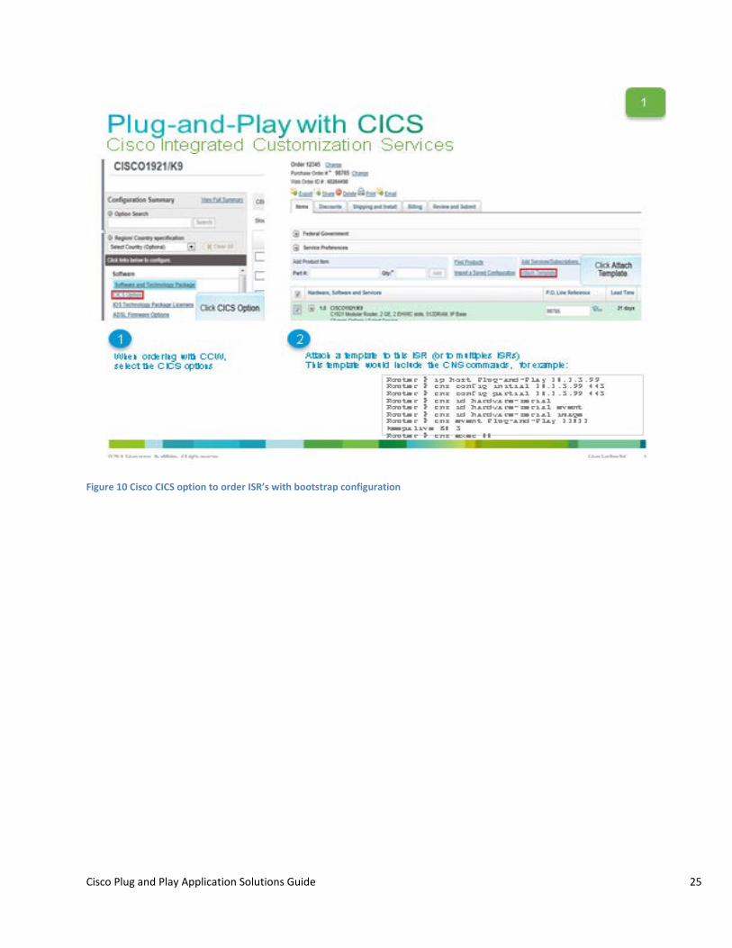
Bootstrap Using Cisco Integrated Customization Services (CICS) In the case where all ISRs (at all the remote sites) share the same bootstrap configuration (e.g. all remote sites use DHCP over Ethernet at the WAN), Cisco Integrated Customization Services (CICS) can be used to load common bootstrap configuration on all ISR from the manufacturing. CICS is used during the ordering process on the Cisco Commerce Workspace (CCW) to inform Cisco to load a specific configuration file on the ISRs being ordered, before shipping them. This helps with high volume zero touch deployment of Cisco ISR G2 routers.
Cisco Plug and Play Application Solutions Guide 25
Figure 10 Cisco CICS option to order ISR’s with bootstrap configuration
Cisco Plug and Play Application Solutions Guide 26
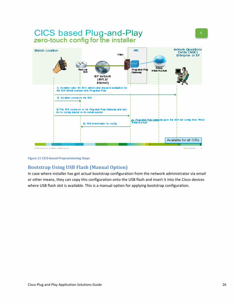
Figure 11 CICS-based Preprovisioning Steps
Bootstrap Using USB Flash (Manual Option) In case where installer has got actual bootstrap configuration from the network administrator via email or other means, they can copy this configuration onto the USB flash and insert it into the Cisco devices where USB flash slot is available. This is a manual option for applying bootstrap configuration.

Cisco Plug and Play Application Solutions Guide 27
Figure 12 USB based Provisioning
Bootstrap Using Auto Install The Cisco IOS software includes a feature, AutoInstall that simplify or automate the configuration on Cisco devices. AutoInstall allows a network manager to load configuration files onto new Cisco devices automatically from TFTP Server. It works in-conjunction with the DHCP Server in the network.
Please refer to the Cisco IOS AutoInstall feature for details on using the Cisco IOS Auto Install software.
Typically, a new router with auto-install feature sends a DHCP request to the DHCP Server for obtaining TFTP server IP address and its own IP address. The device now obtains the configuration files from TFTP server. Cisco Prime Infrastructure can act as a TFTP server here. After the router gets its configuration files, it will load and boot up using it. After the device boots up, it connects to the Cisco Plug and Play Gateway for obtaining further Day1 configuration and any image files, specified for it in the Cisco Plug and Play Profile.

Cisco Plug and Play Application Solutions Guide 28
Figure 13 Bootstrap using AutoInstall
Prerequisites:
• Cisco Prime Infrastructure and Cisco Plug and Play Servers are running. • DHCP Server is configured in customer network and has Cisco Prime Infrastructure specified as
TFTP Server. • New Cisco device has auto install feature available. • Cisco Prime (TFTP Server) has bootstrap configuration in a file called “network-confg.cfgtpl”.
Refer the “Delivering bootstrap using TFTP” section above. • Note: The filename must be network-confg.cfgtpl and cannot be changed to anything else. • DHCP Pool must have enough IP addresses. • Setup components are in the same subnet.
Steps for bootstrap using Auto Install
Step 1: Follow the steps to create Plug and Play Profile on Cisco Prime Infrastructure.
Step 2: Follow the steps in the “Delivering bootstrap using TFTP” section to generate a bootstrap configuration with filename network-confg.cfgtpl.
Step 3: Configure the DHCP Server with Option 150 for TFTP Server IP address.
When the router does not find any startup configuration, auto install script in the router is executed. The auto-install script will automatically send a DHCP broadcast and receive IP Address from the DHCP Pool. The option 150 specified in the DHCP Server, enables it to respond with the TFTP Server IP address to the device. Now the device contacts the TFTP Server and gets its initial bootstrap configuration. After the device loads and boots up using this bootstrap configuration, it will establish contact with the Cisco Plug and Play Server for Day 1 configuration and image files, as specified in the Cisco Plug and Play Profile.

Cisco Plug and Play Application Solutions Guide 29
Bootstrap Using Cisco Configuration Professional Express (CCP Express) Cisco Configuration Professional Express (CCP Express) is a lightweight version of Cisco Configuration Professional (CCP), is an embedded device manager that is available on the router flash memory. It can be used to configure some of the LAN and WAN interfaces and basic configurations of the router to bootstrap the router. By default, the Cisco CP Express is made available on the router flash memory.
CCP Express version 2.7 has added support for Cisco Plug and Play bootstrap configuration. It allows specifying the Plug and Play Gateway IP address/hostname and an optional image upgrade commands. After CCP Express is configured, it puts the basic CNS bootstrap connectivity commands on the device, to enable call home functionality. When the device has CNS bootstrap commands, it will contact the Cisco Plug and Play gateway and initiate Day1 configuration and optional image download process.
Figure 14 Cisco Plug and Play Settings
For more information, please refer to the CCP Express documentation.
Bootstrap Using Smart Install This option is mainly applicable to Cisco Switches which support “Smart Install” feature. Typically, Cisco Switches have a similar configuration that needs to be applied to all switches. With this option, Cisco Prime Infrastructure acts as a TFTP Server. Cisco Plug and Play deployment Profile can be saved in the Cisco Prime Infrastructure TFTP directory using Deploy->Add Device->Bootstrap Configuration->TFTP option. Smart Install enabled Director Cisco Switch configuration specifies Cisco Prime Infrastructure as a TFTP Server. When Director Switch pulls configuration from the Cisco Prime Infrastructure, which is a bootstrap configuration, all aggregation switches connected to this Director gets this bootstrap configuration and will be able to call home to Cisco Prime Infrastructure for further deployment of Day 1 configuration or Image File.
Cisco Plug and Play Applications As mentioned in the above bootstrapping options, there are various ways to apply bootstrap configuration to a device. There are standalone Plug and Play deployment applications that can be used to apply bootstrap configurations. These applications are useful when auto install or any other

Cisco Plug and Play Application Solutions Guide 30
mechanism is not available for bootstrapping, and customers are interested in using automatic methods for applying bootstrap configurations.
The Cisco Plug and Play Solution provides IPhone/IPad based Mobile standalone Application (iOS based) that can be downloaded from iTunes. The Cisco Plug and Play solution is also integrated into the Cisco Prime Mobile Application which is also available on iTunes Apple App Store.
The Cisco Plug and Play Solution also provides Desktop/Laptop based standalone Application (Windows based) that can be downloaded from Cisco using a CCO login.
Depending on the availability of resources at the remote branch site, the installer can use one of these applications to bootstrap the device. The functionality and flow provided in both these applications are the same. However, you may see a slight variation in the look and feel due to the underlying difference in the Operating System.
Figure 15 Cisco Plug and Play Application based provisioning
Prerequisite for using IPhone/IPad Deployment Application
Installer must purchase a special cable (C2-RJ45V) from “Redpark” vendor, and connect one end of the cable to the IPhone/IPad USB cable and the other end to the blue console port of the Cisco device. For more information on the C2-RJ45V cable, refer http://www.redpark.com/c2rj45.html.

Cisco Plug and Play Application Solutions Guide 31
Redpark Console Cable C2-RJ45V
Connect one end of the cable to the IPhone/IPad USB port and the other end to the blue console port of the Cisco device.
Figure 16 Redpark Console Cable (c2-RJ45V)
Prerequisite for using Desktop/Laptop PC based Deployment Application
Installer must have either a USB Type A to Mini USB type B convertor or a USB to Serial Adapter available for connecting to the Cisco device. Cisco ISR G2 Series routers have mini USB console port that can be used for the deployment. Cisco 8xx Series ISR routers do not have mini USB console port; and can use USB to Serial adapter for deployment.
Figure 17 Sample USB type A to mini USB type B cable

Cisco Plug and Play Application Solutions Guide 32
Figure 18 Sample USB to Serial adapter
Bootstrap Flow Using Cisco Plug and Play Application The Cisco Plug and Play Application works in two modes.
• If the device on which Cisco Plug and Play Application is installed (IPhone or Desktop) has a 3G connectivity to the Cisco Plug and Play Gateway, the deployment can be done immediately at the remote branch site.
• If the device on which Cisco Plug and Play Application is installed (IPhone or Desktop) has no 3G connectivity to the Cisco Plug and Play Gateway, a bootstrap configuration can be pre-downloaded from a place where connectivity to the server is available. After the bootstrap configuration is downloaded, this configuration is stored locally on the device (IPhone/laptop/IPad). The installer can then go to the remote site and use this pre-downloaded bootstrap to start the deployment.
After the required cable is connected to the Cisco device and the other end of the cable is connected to the user device (IPhone/IPad/Desktop/Laptop, the deployment can begin.
To begin deployment when the device has network connectivity to the Cisco Prime Plug and Play Gateway (3G or Ethernet), perform these steps.
Step 1 Launch Cisco Plug and Play Application.
Step 2 From the initial launch screen, click Settings.
Step 3 Specify the Cisco Prime Plug and Play Gateway Address.
Step 4 Specify the Cisco Prime Infrastructure username and password.
It is recommended to create a non-root user in Cisco Prime Infrastructure with the appropriate privileges. Refer to the Cisco Prime Infrastructure User Guide for information on creating users and assigning privileges to them.
Step 5 Click Test Connection to make sure the device can connect to the server. Defining the server entry is only required for the first time use of the Cisco Plug and Play Application, after which it will store the server information.
Step 6 Click Deploy icon to start the deployment.

Cisco Plug and Play Application Solutions Guide 33
Step 7 If a pre-downloaded bootstrap configuration is found, you are asked to confirm if it can be used for deployment or you want to download a bootstrap configuration again. If no pre-loaded configuration is found, you are prompted to specify the PIN (as specified in Step 8).
Step 8 After the deployment starts, you are prompted for the PIN. Enter the PIN information provided by the administrator and click OK.
Step 9 After the deployment is completed, a status message indicating Success or Failure is displayed. Green indicates “Deployment Completed”, and red indicates “Deployment Failed”.
Step 10 (Optional) Network Administrator can view the status of the deployment for all devices going through deployment using the Operate->Plug and Play Status menu option in Cisco Prime Infrastructure.

Cisco Plug and Play Application Solutions Guide 34
Figure 19 Cisco Plug and Play Application Launch Page

Cisco Plug and Play Application Solutions Guide 35
Figure 20 Cisco Plug and Play Application Settings Page

Cisco Plug and Play Application Solutions Guide 36
After the deployment has begin, the Cisco Plug and Play Application prompts you for the Device PIN number. You must obtain this PIN number from your network administrator using Email PIN option or manaually.

Cisco Plug and Play Application Solutions Guide 37
Figure 21 Specify the PIN in Cisco Plug and Play Application

Cisco Plug and Play Application Solutions Guide 38
After the deployment is completed, the Cisco Plug and Play Application displays the status of the deployment as shown below.

Cisco Plug and Play Application Solutions Guide 39
Figure 22 Deployment Status of the Cisco Plug and Play Application

Cisco Plug and Play Application Solutions Guide 40
Note: You can also view the logs when the deployment is in progress using the “ON/OFF” slider for Show Deployment Logs on the top-left corner.
Follow the steps detailed below to download the configuration and perform deployment at a later time. Use this procedure when the device does not have any network connectivity to the Cisco Prime Plug and Play Gateway from the remote branch itself.
Step 1 Launch Deployment Application.
Step 2 From the initial launch screen, click Settings.
Step 3 Specify the Cisco Prime Plug and Play Gateway Address.
Step 4 Specify the Cisco Prime Infrastructure username and password.
It is recommended to create a non-root user in Cisco Prime Infrastructure with appropriate privileges. Refer to the Cisco Prime Infrastructure User Guide for information on creating users and assigning privileges to them.
Step 5 Click Test Connection to make sure the device can connect to the server. Defining the Server entry is only required for the first time use of the Cisco Plug and Play Application, after which it will store the server information.
Step 6 Click the Download icon to start the deployment.
Step 7 Enter PIN number when prompted. The bootstrap configuration will be downloaded and stored locally on the device.
Step 8 When you are ready to begin deployment, click the Deploy icon or click Start Deployment (and follow the steps outlined above when connectivity to the server is available).

Cisco Plug and Play Application Solutions Guide 41
Figure 23 Cisco Plug and Play Application - Starting device deployment from “Downloads” page

Cisco Plug and Play Application Solutions Guide 42
Troubleshooting Information Use this section for common self-help topics or issues that may come up during deployment. Please contact Cisco TAC for further assistance or help.
Recommended Versions Follow this version recommendation as a potential first step in correcting any issues.
• In general, Cisco recommends Cisco Prime Infrastructure version 2.0 and higher for integrated Cisco Plug and Play Solution.
• Cisco Plug and Play Applications support Cisco Prime Infrastructure version 1.3 and higher. Cisco Plug and Play Applications do not work with Cisco Prime Infrastructure 1.2 version. However, for Cisco Prime Infrastructure 1.2 customers, other mechanisms of applying bootstrap (eg: Exporting, TFTP, Email, USB Flash etc.) are still available. Cisco Plug and Play Mobile Application must have base iOS version 6.0 or higher.
• Cisco Plug and Play Windows PC Application must be installed on Windows XE or Windows 7. • Cisco Devices must have IOS version 12.3 or higher for better compatibility with embedded CNS
agents on the device.
Installation and Setup Issues Use this section for tips on any installation or set up issues with the Cisco Plug and Play solution components.
• Cisco Prime Infrastructure version 1.2: Cisco Prime Infrastructure 1.2 does not have any CLI to export server certificate out of
the VM. o Option 1: Use the following command from Cisco Plug and Play Gateway VM to get the certificate out from Cisco Prime Infrastructure VM.
Step 1: Log in to Cisco Plug and Play Gateway VM using admin credentials.
Step 2: Run the command below. Make sure Cisco Prime Infrastructure server is up and running before running the following command.
“openssl s_client -connect "PI_MOM_HOST_NAME:61617" 2>&1 | sed -ne '/-BEGIN CERTIFICATE-/,/-END CERTIFICATE-/p' > ncsserver.crt”
Note: Replace PI_MOM_HOST_NAME with the IP address or the hostname of the Cisco Prime Infrastructure server. This command will save the Prime Infrastructure certificate in a file called “ncsserver.crt”. Use this file during “pnp setup” command to import the certificate.

Cisco Plug and Play Application Solutions Guide 43
o Option 2 : Use any web browser such as Internet Exporter or Mozilla Firefox to access Cisco Prime Infrastructure secure web url (for example: https://prime-server). A warning dialog to accept the server certificate is displayed. At this point, click to view the certificate and export it to a file. Use Cisco Plug and Play Gateway VM and get this certificate using a “copy” CLI. Use this CLI during the “pnp setup” command to import the certificate.
This setup step is not required with Prime Infrastructure 2.0 version. Cisco Plug and Play Gateway will handle the server certificate export during the setup command.
• Cisco Prime Infrastructure server must always be installed, and must be up and running before doing separate DMZ installations of the Cisco Plug and Play Gateway.
• Refer to the Cisco Prime Infrastructure Quick Start Guide and User Guide for information on the installing the server.
• Refer to the Cisco Prime Infrastructure Command Reference Guide for information on using the Cisco Plug and Play Commands or CLI.
Connectivity Issues If Cisco Prime Infrastructure and Cisco Plug and Play Gateway are installed on separate machines, ensure that there is IP connectivity between both these servers.
• Make sure there is IP connectivity between the Cisco Prime Infrastructure and Cisco Plug and Play Gateway servers. Run the following command verify the connectivity. “netstat -an | grep EST | grep 61617” If there is no output, it means that there are no connections established. Either the Cisco Plug and Play Gateway or the Cisco Prime Infrastructure server is not functioning or has not started. Restart these servers as listed in the sequence below.
• Follow proper sequence for bringing up and restarting the server. Cisco Prime Infrastructure should always be the first server to be brought up, followed by the Cisco Plug and Play Gateway. If you have restarted Cisco Prime Infrastructure for any reason, Cisco Plug and Play Gateway server must also be restarted. Both the server must always be in sync.
• If the Cisco Plug and Play Gateway is installed in the DMZ zone, ensure that you open up the required ports on the firewall. After these ports are opened up, the Cisco Plug and Play Gateway will be able to receive events from the Cisco device. Cisco Plug and Play Gateway requires the following ports to be opened up on firewall:
o 11011 to 11022 (All ports as seen in “pnp status” output on the Cisco Plug and Play Gateway)
o 8080 o 8443 o 8045 o FTP ports/data ports (part of the FTP message exchange)

Cisco Plug and Play Application Solutions Guide 44
• Ensure that the Cisco device is able to ping the Cisco Plug and Play Gateway and IP connectivity exists between them.
Checking the Status of the Servers In order to verify that the Cisco Plug and Play Servers are up and running, use the following commands:
Cisco Plug and Play Gateway Server: (If installed separately only)
“PNP {status|start|stop|restart|reload|enable|disable}”
If everything is okay, the command output will indicate “Plug and Play Gateway is running”. In case of the output will display the issue. In case of issues, restart the Cisco Plug and Play Gateway.
Sample Output:
Plug and Play Gateway is running.
Prime Infra Server:
Use the following command to verify the status of the Cisco Prime Infrastructure server. This will also include the status of the Cisco Plug and Play Gateway, if they are installed on a single box or are for non-DMZ deployments.
“ncs status”
Sample Output:
Health Monitor Server is running.
Compliance engine is running.
Ftp Server is running
Database server is running
Tftp Server is running
Matlab Server is running
NMS Server is running.
Plug and Play Gateway is running.
SAM Daemon is running ...
DA Daemon is running ...
Syslog Daemon is running ...

Cisco Plug and Play Application Solutions Guide 45
Collecting Logs Logs are useful to further troubleshoot any issue and contact Cisco TAC.
Cisco Plug and Play Gateway: (only if installed separately)
Use the following command on the VM where Cisco Plug and Play Gateway is installed separately. Use “copy” command to get the log file out of the VM.
admin# pnp tech log
The System Status file created: /localdisk/20121003032209.pnp_systemmonitor.tar.gz
Cisco Prime Infrastructure Server:
Go to Administration->Log Settings and download the log file.
Cisco Plug and Play iOS application (IPhone/iPad mobile App)
Email server settings must be configured on your IPhone/Ipad before logs can be sent out. Click “Settings” icon in the App, and use the “Email Support Logs” option to email the support logs. The Application will use the email account configured to send the logs to Cisco TAC for any general application issue.

Cisco Plug and Play Application Solutions Guide 46
Figure 24 Cisco Plug and Play Application – Emailing Support Logs

Cisco Plug and Play Application Solutions Guide 47
You can also send the device deployment logs to the network administrator or to Cisco TAC for any general App issues.
The below screen shot describes accessing the per device deployment logs. You must swipe the “Deployment Logs” option to view the email option.

Cisco Plug and Play Application Solutions Guide 48

Cisco Plug and Play Application Solutions Guide 49
You can monitor the status of deployment while the deployment is in progress using enable/disable log viewing option.

Cisco Plug and Play Application Solutions Guide 50
Figure 25 Monitoring Deployment Status on the Cisco Plug and Play Application

Cisco Plug and Play Application Solutions Guide 51
Cisco Plug and Play PC application (Windows App)
Cisco Plug and Play Application on Windows does not have a built-in email option yet. You must use the menu option to “Collect Logs”. The logs are in a compressed zip file format, and can be emailed to the network administrator or Cisco TAC for general App issues. The device deployment logs can be collected from “Deploy” or “Download” option on the App and sent to the network administrator.
Cisco Routers/Switches with Cisco CNS Agent Use this section to troubleshoot issues on the Cisco devices that have Cisco CNS agent running on it.
Refer to the Cisco CNS Documentation guide for detailed help with any of the commands listed here.
• Enable CNS logs and capture debug output Router> config t Router> enable Router> debug cns all Router> ter mon
• Use “show cns event” CLI to see the active connections. Router#show cns event connections The currently configured primary event gateway: hostname is ciscoprimepnp. port number is 11013. encryption is disabled. Event-Id is FTX14068095 Keepalive setting: keepalive timeout is 120. keepalive retry count is 2. Connection status: Connection Established.
• If Cisco Plug and Play Application fails at “Waiting for CNS initial CLI to be removed”, log in to the Cisco device and apply no form of the “cns event” command, and add it back again. This should trigger call home again to the Cisco Plug and Play server, in case of an issue with CNS agent on the device.
• The Plug and Play Deployment Status can be monitored in real- time from Cisco Prime Infrastructure server using the “Operate->Plug and Play Status”. The detailed status of the deployment is displayed. If there are no entries for the Cisco device in operation, it means that bootstrapping has not yet been applied to this device. Use one of the bootstrapping options mentioned earlier in the document to trigger the deployment.

Cisco Plug and Play Application Solutions Guide 52
Redeploying the Already Deployed Devices In order to redeploy the already deployed devices, you must clean up the deployed profiles in Cisco Prime Infrastructure. Unless this is done, re-deploying already deployed device is not allowed.
Follow the steps below to clean up the devices and profiles from the Cisco Prime Infrastructure server.
Step 1: Go to “Operate->Plug and Play Status” and remove the device that you want to redeploy (identify the device by its serial ID).
Step 2: Go to “Deploy->Plug and Play Profiles” and select the profile.
Step 3: Click “Unpublish” to unpublish this profile.
Step 4: Click “Deploy” and select device listed in the profile.
Step 5: Click “Delete” to remove the device.
Step 6: Go to “Feature->Plug and Play Profiles->”, select the profile and hover the mouse on it. Click “Delete” to remove the profile.
References • Cisco Prime Infrastructure Quick Start Guide • Cisco Prime Infrastructure User Guide • Cisco Prime Infrastructure Command/CLI Reference Guide (includes Plug and Play related
commands/CLI) • Cisco Plug and Play Application Deployment User Guide • Cisco Auto Install Guide • Cisco Smart Install Guide • Cisco IOS CNS Documentation • Cisco IOS CNS CLI • Cisco IOS Auto Install Feature • Cisco Commerce Workplace (CCW) integrated, Cisco Integrated Customization Services (CICS)
for ISR G2 • Cisco Configuration Professional Quick Start Guide • Cisco Configuration Professional Express (CCP Express) version 2.7 Plug and Play Settings

Cisco Plug and Play Application Solutions Guide 53
Cisco and the Cisco logo are trademarks or registered trademarks of Cisco and/or its affiliates in the U.S. and other countries. To view a list of Cisco trademarks, go to this URL: www.cisco.com/go/trademarks. Third-party trademarks mentioned are the property of their respective owners. The use of the word partner does not imply a partnership relationship between Cisco and any other company. (1110R)
Any Internet Protocol (IP) addresses and phone numbers used in this document are not intended to be actual addresses and phone numbers. Any examples, command display output, network topology diagrams, and other figures included in the document are shown for illustrative purposes only.
Any use of actual IP addresses or phone numbers in illustrative content is unintentional and coincidental.
© 2013 Cisco Systems, Inc. All rights reserved.