cisco nexus fabric manager walkthrough garry lemasa, technical marketing engineer, cisco network...
TRANSCRIPT

Cisco Network Fabric Manager
© 2017 Cisco and/or its affiliates. All rights reserved. Page 1 of 19
Cisco Nexus Fabric Manager Walkthrough
This document provides a walkthrough of deploying a VXLAN fabric underlay using the Cisco
Network Fabric Manager.
Author: Garry Lemasa, Technical Marketing Engineer, Cisco Network Fabric Manager, with
contributions by Salvatore Ventura and Tom Nosella.
v1.1
June 13, 2017
© 2017 Cisco and/or its affiliates. All rights reserved. Page 2 of 19
Table of Contents
A NEW WAY OF BUILDING AND MANAGING VXLAN SPINE/LEAF FABRICS ...................................... 3
SCOPE ............................................................................................................................................ 3
ASSUMPTIONS .................................................................................................................................... 4
USER INTERFACE OVERVIEW .................................................................................................................. 4
STAGE ONE – DEPLOY SWITCH SOFTWARE ...................................................................................... 5
AUTO-FABRIC PROVISIONING OR DISCOVERY IMPORT ................................................................................. 6
UPLOAD AN NXOS IMAGE WHEN DISCOVERY IMPORT IS USED ..................................................................... 7
STAGE TWO – CREATE A SWITCH PROFILE ....................................................................................... 7
STAGE THREE – CONFIGURE SWITCHPOOL SETTINGS ...................................................................... 9
STAGE FOUR - IMPORT SWITCHES ................................................................................................. 11
OPTION #1 - AUTO FABRIC PROVISIONING ............................................................................................. 11
OPTION #2 - DISCOVERY IMPORT ......................................................................................................... 13
STAGE FIVE - UPGRADE NXOS SOFTWARE ..................................................................................... 15
CREATE AN UPGRADE GROUP ............................................................................................................... 15
START THE NXOS SOFTWARE UPGRADE ................................................................................................. 16
STAGE SIX – SET SWITCHES TO MANAGED MODE ......................................................................... 17
OTHER CONSIDERATIONS ............................................................................................................. 18
A FULLY MANAGED AND AUTOMATED VXLAN UNDERLAY ............................................................ 19
© 2017 Cisco and/or its affiliates. All rights reserved. Page 3 of 19
A New Way of Building and Managing VXLAN Spine/Leaf
Fabrics
Building a VXLAN/EVPN infrastructure can be challenging. Administrators and network engineers
can invest days with the switch command line and scripts configuring many switches in different
roles. This manual process is inefficient, tends to be error prone and requires extensive knowledge
of CLI commands and protocols. Off the shelf network management options can assist in this
process, but they tend to be element based, implementing commands on a switch-by-switch basis
and still require extensive knowledge of CLI protocols.
Enter the Cisco Nexus Fabric Manager (NFM). NFM is a Data Center fabric manager that simplifies
and automates the creation and management of VXLAN/EVPN spine/leaf environments. Built to be
fabric aware, NFM actively builds and manages both the underlay, as well as overlay connectivity.
The simple user interface enables administrators to focus on how they want to design their fabric,
while NFM determines and pushes the required configurations down to any Nexus 9000 switch.
NFM has also been designed to assist in all phases of a fabric lifecycle, simplifying and automating
tasks such as adding hosts and switches, building layer 2 and 3 connectivity, troubleshooting issues
and reporting on network health.
Even better, NFM actively manages the VXLAN underlay entirely on its own, with no user
involvement necessary.
Scope
The objective of this document is to provide an example walkthrough of building a new VXLAN
spine/leaf underlay with the Cisco NFM, resulting in a fabric that is ready to have hosts attached
and overlays created.
There are six stages of building a VXLAN spine/leaf underlay with the Cisco Nexus Fabric Manager,
including:
Deciding on NXOS software
Building switch profiles
Modifying switchpool settings
Import switches into the switchpool
Upgrading the NXOS software image
Setting switches to managed mode - building the underlay

© 2017 Cisco and/or its affiliates. All rights reserved. Page 4 of 19
We will use the topology in Figure 1 below that is a simple spine/leaf architecture with two Nexus
9372 switches as spines and two Nexus 9372 switches as leafs.
Figure 1 –VXLAN spine/leaf topology
Assumptions
Note the following assumptions:
All four switches are racked, cabled and powered on.
The NFM appliance is installed and configured according to the Cisco Nexus Fabric Manager
Quick Start guide. Also, the mgmt0 interface on the switches and the appliance are able to
communicate with each other on the same management network.
We are using NFM version 1.2(x) for this document. If you are using an earlier version we
recommend that you upgrade before building your VXLAN fabric.
User Interface Overview
To enter NFM, type the appliance management IP address into a web browser (both Chrome and
Spine 1
N9K-C9372TX
10.23.235.50
Spine 2
N9K-C9372TX
10.23.235.51
Leaf 1
N9K-C9372TX
10.23.235.53
Leaf 2
N9K-C9372TX
10.23.235.54
NFM
Host14 Host15

© 2017 Cisco and/or its affiliates. All rights reserved. Page 5 of 19
Firefox are supported), and enter the appropriate login credentials.
Upon logging in, NFM displays the home screen illustrated below.
Figure 2 – Nexus Fabric Manager Home Screen
Most of the procedures in this document start from this screen. Key features of the home screen
include the following:
Navigation Menu button in the upper left
Settings Menu in the upper right
Tabs across the middle of the screen such as INTERFACES, SWITCHES, SETTINGS, etc.
Clicking the Navigation Menu button in the upper left and selecting Home from the menu
dropdown options returns to this home screen.
Stage one – deploy switch software
Before beginning the underlay build, administrators should determine which version of NXOS switch
software they want to deploy. Note that while any supported image listed in the Nexus Fabric
Manger release notes can be used, we recommend selecting the latest version in the release train
to take advantage of updates and fixes. NXOS images can be uploaded to NFM from a laptop or
server (after an authorized user downloads it from the cisco.com website).
Note: Once the switches have been imported into NFM, it automatically loads the NXOS image
already installed on a Nexus 9000 into the NFM image catalog, This is helpful when a new
switch is added and administrator wants to upgrade the fabric to the newer switch image.

© 2017 Cisco and/or its affiliates. All rights reserved. Page 6 of 19
Auto-Fabric Provisioning or Discovery Import
Administrators use one of the following two methods to import switches into the NFM switchpool,
which will then deploy the chosen version of the NXOS software:
Auto-Fabric Provisioning (AFP) – Choose AFP to import out-of-the-box, powered on
switches all at once. For AFP, the NFM Image Catalog must contain the image of NXOS that it
will deploy, according to the NFM profile (discussed in stage 2). The AFP method applies the
same NXOS image to all switches.
NFM uses built in Power On Auto Provisioning (POAP) server capabilities to push an initial
configuration file to new switches, automatically adding them to the switchpool in
“monitored” (read-only) mode or “managed” mode depending on the AFP configuration.
When using NFM version 1.2(3) or lower, the if0 interface on the appliance must be
configured with an IP address in the same subnet as the switches you would like to import.
In NFM version 1.3(1) or later, AFP functionality only requires a mgmt0 interface. For
instructions on how to configure either interface, please refer to the NFM Quick Start guide.
To add switches to the fabric, administrators will also want to have a list of switch serial
numbers and desired management IP addresses for each switch in the fabric, that they will
use to add switches to the fabric.
Discovery Import – This option enables administrators to import switches without making
changes to the NXOS image on existing devices. Administrators who prefer to power on
switches and apply initial configuration information or “kick the tires” before use can use the
Discovery Import process.
When an administrator initially configures switches with a management IP address and
username/password using the CLI and/or the NXOS setup utility, Discovery Import begins by
manually adding an initial switch to the switchpool. Then, NFM reaches out to neighboring
switches through the Cisco Discovery Protocol (CDP) and the Link Layer Discovery protocol
(LLDP), attempting to reach every connected manageable switch.
Discovery import is useful for administrators who prefer to run the initial startup routine on
new switches for verification purposes. Unlike the AFP process, NXOS is not updated through
the profile selection (see Stage Two). This enables administrators to import switches into the
switchpool without changing the image. With Discovery import, the NXOS image is updated
later in the process via an upgrade group (see Stage five below).

© 2017 Cisco and/or its affiliates. All rights reserved. Page 7 of 19
Both approaches are equally valid for initial switch import into NFM.
Upload an NXOS image when Discovery Import is used
The following process details how to manually upload an image of NXOS into the NFM image
catalog. The upload process steps are also used for upgrade groups that are discussed in stage five.
Because NXOS image files are large, use a local or fast broadband connection. Propagation delay
from long distances and deep packet scanning can also significantly slow down a large file transfer.
Once uploaded, the image resides in the image catalog where NFM can use it to upgrade switches
during AFP import or for the creation of upgrade objects.
Figure 3 - NFM NXOS image catalog
Complete the steps below to upload a NXOS image into the NFM image catolog:
1. From the Navigation menu, choose Images, click Settings, and, from the drop-down list,
choose Upload new image.
2. Click CHOOSE FILES, browse for the correct NXOS image file then click Open, and click
UPLOAD.
Note: The upload steps are also used for upgrade groups, discussed in Stage six below.
Stage two – create a switch profile
Profiles simplify the configuration of multiple switches or switch interfaces, enabling administrators
to configure a variety of features, and propagate those features to all of the profile members.
Changes to a profile are automatically propagated to the objects they are linked to. Profiles can be
assigned to either switches or interfaces based on their role as configured in the switchpool

© 2017 Cisco and/or its affiliates. All rights reserved. Page 8 of 19
settings.
Before building the underlay, assess whether all of your switches use the same credentials.
If all switches share the same credentials, create one switch profile titled all_switches (or
something else appropriate) and enter the credentials. This prevents the need to enter credentials
manually for each switch.
Note: As a best practice, the NFM configuration guide recommends creating a separate user
account on the switch (for example: nfmservice) with the role “network-admin" and use the
account when adding a switch.
When fabrics have switches with differing credentials, administrators should consider ways to
consolidate those switches into easily remembered groups and assign a profile to each. For example,
leaf_switches and spine_switches could be separate profiles with separate credentials for each.
The profile can designate the initial NXOS switch image that NFM pushes to the switches in the
fabric as part of the initial build.
Note: If Auto Fabric Provisioning is chosen for initial switch import, NFM automatically applies
the designated image. Switches that are imported into NFM through discovery can be
upgraded as part of an upgrade group.
Each switch can only reference one switch profile while a switch profile can be referenced by
multiple switches. Many features can be enabled within profiles using the “+/-” button next to each
feature option. A “-” indicates that the feature is enabled and is no longer grayed out.
Refer to the Profile Management chapter of the configuration guide for more information regarding
profiles.
© 2017 Cisco and/or its affiliates. All rights reserved. Page 9 of 19
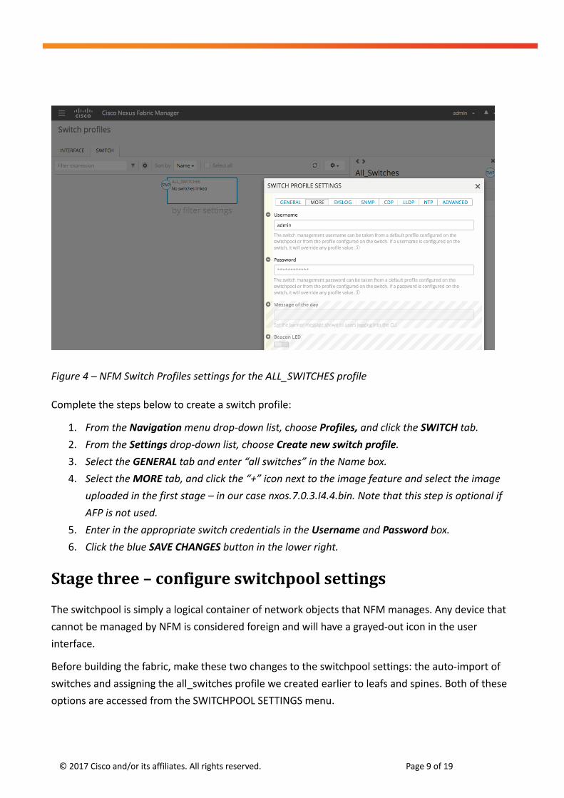
Figure 4 – NFM Switch Profiles settings for the ALL_SWITCHES profile
Complete the steps below to create a switch profile:
1. From the Navigation menu drop-down list, choose Profiles, and click the SWITCH tab.
2. From the Settings drop-down list, choose Create new switch profile.
3. Select the GENERAL tab and enter “all switches” in the Name box.
4. Select the MORE tab, and click the “+” icon next to the image feature and select the image
uploaded in the first stage – in our case nxos.7.0.3.I4.4.bin. Note that this step is optional if
AFP is not used.
5. Enter in the appropriate switch credentials in the Username and Password box.
6. Click the blue SAVE CHANGES button in the lower right.
Stage three – configure switchpool settings
The switchpool is simply a logical container of network objects that NFM manages. Any device that
cannot be managed by NFM is considered foreign and will have a grayed-out icon in the user
interface.
Before building the fabric, make these two changes to the switchpool settings: the auto-import of
switches and assigning the all_switches profile we created earlier to leafs and spines. Both of these
options are accessed from the SWITCHPOOL SETTINGS menu.

© 2017 Cisco and/or its affiliates. All rights reserved. Page 10 of 19
Complete the steps below to update the switchpool settings:
1. From the Navigation menu drop-down list, choose Home, and click the SETTINGS tab. The
switchpool pane appears on the right.
2. Click the EDIT button on the switchpool pane. The SWITCHPOOL SETTINGS menu opens.
3. Click on the Auto-Import switches button and enable it as in Figure 5. The button appears
blue.
Figure 5 – The NFM SWITCHPOOL SETTINGS window.
Auto-import switches – Since we want NFM to automatically import neighbor switches
discovered through CDP and LLDP, enable this feature. This feature automatically imports
switches but leaves them in monitored or “read-only” mode. In the case where customers
have switches in the fabric that NFM is not intended to manage, those devices can be left in
monitored mode or administrators can disable the auto-import switch feature and manually
add the switches as needed at a later time.

© 2017 Cisco and/or its affiliates. All rights reserved. Page 11 of 19
Default profiles for leaf and spine switches – Assign the all_switches profile created earlier
to both leaf and spine switches, eliminating the need to manually enter user id and
passwords for each switch.
In the Default Profiles section of the SWITCHPOOL SETTINGS window, complete the steps below:
4. Click on the drop-down menu under Leaf switch and select all_switches
5. Click on the drop-down menu under Spine switch and select all_switches
Now, the SWITCHPOOL SETTINGS window should match the changes shown in figure 4.
6. Click the blue SAVE CHANGES button in the lower right.
Stage four - import switches
As discussed earlier, switches need to be imported either through Auto Fabric Provisioning or the
Discovery import process.
Note: During switch import, a number of red errors display until the switches are fully
imported. This is normal and the error messages turn blue as the process completes.
Option #1 - Auto Fabric Provisioning
First let’s walk through the Auto Fabric Provisioning process. In our example, there are four switches
with the following serial numbers and the mgmt0 IP addresses we want to assign:
Switch Mgmt0 Serial Number
Spine 1 10.23.235.50 SAL1924GQTC
Spine 2 10.23.235.51 SAL19048JKY
Leaf 1 10.23.235.53 SAL1913C6YF
Leaf 2 10.23.235.54 SAL1924GQXP
Table 1 – Auto-Fabric Provisioning information

© 2017 Cisco and/or its affiliates. All rights reserved. Page 12 of 19
To import the spine switches with AFP:
If all spines in the fabric are Nexus 9500 switches, the NFM will automatically detect the
model number and assign these models the roles of spines. However, if a spine switch is a
Nexus model 9300 or 9200 switch then the spine role will need to be assigned manually.
Since we are using Nexus 9372TX switches, we will be assigning Spine1 and Spine2 the role
of spine in Step 6 below.
Complete the steps below to import spine switches with AFP:
1. From the Navigation menu, choose Home and click the SWITCHES tab.
2. From the Settings menu, choose Import new switch. The ADD SWITCH dialog box
appears with the following tabs: GENERAL and MORE.
3. Click in the field under Management address and enter the Spine 1 IP address, in our
case 10.23.235.50
4. Click in the field under Serial number and enter the Spine 1 Serial number, in our case
SAL1924GQTC
5. Click the MORE tab, and in the field under Name enter Spine1
6. In the field under Role, select Spine from the dropdown menu.
7. Click the blue SAVE CHANGES button in the lower right.
NFM initiates the process of importing Spine1.
Repeat the above process for Spine2, entering the appropriate IP address, serial number
and Spine2 as a name.
There is no need to wait for the importing of a switch to finish before entering new
information. NFM tracks and manage actions as they are entered into the user interface.
To import the leaf switches with AFP:
The procedure for importing the leaf switches is a step shorter since we do not have to
designate their role. NFM automatically designates switches other than Nexus 9500’s as
leafs.
Complete the steps below to import leaf switches with AFP:
1. From the Navigation drop-down list, choose Home, and click the SWITCHES tab.
2. From the Settings menu, choose Import new switch. The ADD SWITCH dialog box
appears with the following tabs: GENERAL and MORE.
© 2017 Cisco and/or its affiliates. All rights reserved. Page 13 of 19
3. Click in the field under Management address and enter the Leaf 1 IP address, in our
case 10.23.235.53
4. Click in the field under Serial number and enter the Leaf 1 Serial number, in our case
SAL1913C6YF
5. Click the MORE tab, and in the field under Name enter Leaf1
6. Click the blue SAVE CHANGES button in the lower right.
Repeat the above process for Leaf2, entering the appropriate IP address, serial number
and name.
Note: As mentioned, if your fabric includes Nexus 9500’s, the NFM will automatically identify
these switches as spines. In this case, administrators would only have to follow the process
of importing leaf switches. Since our example fabric uses Nexus 9372’s for spines, we import
spines and leafs as separate processes.
It is also possible for switches to be imported directly into a managed state from the Import
new switch dialog box (Step – 3 above), in the Management state dropdown menu, selecting
Managed as an option. In this document, we are importing switches as a separate stage to
illustrate the process for new users.
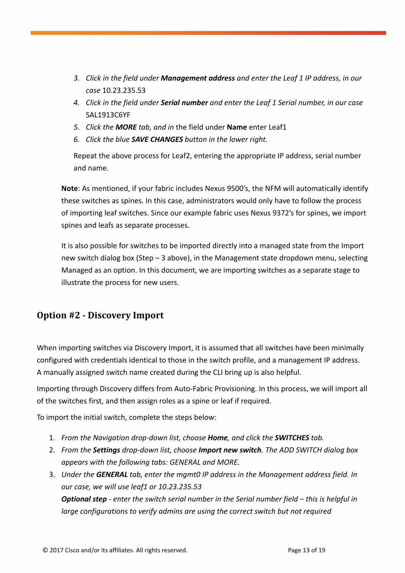
Option #2 - Discovery Import
When importing switches via Discovery Import, it is assumed that all switches have been minimally
configured with credentials identical to those in the switch profile, and a management IP address.
A manually assigned switch name created during the CLI bring up is also helpful.
Importing through Discovery differs from Auto-Fabric Provisioning. In this process, we will import all
of the switches first, and then assign roles as a spine or leaf if required.
To import the initial switch, complete the steps below:
1. From the Navigation drop-down list, choose Home, and click the SWITCHES tab.
2. From the Settings drop-down list, choose Import new switch. The ADD SWITCH dialog box
appears with the following tabs: GENERAL and MORE.
3. Under the GENERAL tab, enter the mgmt0 IP address in the Management address field. In
our case, we will use leaf1 or 10.23.235.53
Optional step - enter the switch serial number in the Serial number field – this is helpful in
large configurations to verify admins are using the correct switch but not required

© 2017 Cisco and/or its affiliates. All rights reserved. Page 14 of 19
4. If you assigned a switch name in the initial NXOS switch startup configuration, skip this step.
If not, click on the MORE tab and enter a name in the Name field. By default, NFM uses the
existing name on a switch if one is not entered here.
5. Click the SAVE CHANGES button.
At this point NFM communicates with, identifies and imports the initial switch into the switchpool in
monitored mode. Once the initial switch has been imported and its interfaces identified, NFM
leverages the Cisco Discovery Protocol (CDP) and Link Layer Discovery Protocol (LLDP) to identify
neighboring devices and import them into the switchpool. Once those switches have been imported
and identified, the process repeats on the next layer of neighboring switches until all manageable
devices have been discovered.
When the import process completes, all four Nexus 9372 switches are located in the switchpool but
the spine roles need to be assigned. Again, if customers are using Nexus 9500 switches for spines,
they are automatically assigned the spine role based on model number.
To assign roles to the spine switches, complete the steps below:
1. From the Navigation menu, choose Home, and click the SWITCHES tab.
2. Click the checkbox in the appropriate switch tiles to select all spine switches, in our case
spine1 & spine2.
3. From the Settings drop-down list, choose Edit selected.
4. From the Role drop-down menu on the GENERAL tab select spine, and click the SAVE button.
The selected switches are configured as spines. Now that the spines have their roles correctly set
we are ready to move to the next stage.

© 2017 Cisco and/or its affiliates. All rights reserved. Page 15 of 19
Stage five - upgrade NXOS software
Note: Skip this stage if Auto Fabric Provisioning was used for the initial switch import as the
switches will already have been updated to the correct version of NXOS.
If Discovery import was used instead of AFP, the NXOS switch image can be upgraded by creating a
switch upgrade group. This procedure can also be used to upgrade switches at a later time.
Create an upgrade group
Upgrades can consist of one upgrade group for all switches or more than one group, each
containing a subset of switches in the fabric. For example, you can divide the fabric into a Side A and
a Side B group. Both are equally valid approaches - choose the methodology that best suits your
environment.
Note: For future upgrades, switches can be in monitored or managed mode and still have their
NXOS image updated.
Figure 6 - All switches upgrade pending
For simplicity sake, we are using one upgrade group named “upgrade-all” in our example.
To create the upgrade group, complete the steps below:
1. From the Navigation Menu, choose Home, and click the SWITCHES tab.

© 2017 Cisco and/or its affiliates. All rights reserved. Page 16 of 19
2. Click the Select all check box to select all switches. (If you are only selecting a subset of
switches for your upgrade group, you will need to click the check box in the bottom right
corner of the switch tiles you want to upgrade.)
3. From the Settings drop-down list, choose Add to new Upgrade.
4. Add a name for the upgrade group/object – in our case named “upgrade-all” and, if desired,
add an description.
5. From the image drop-down menu choose the desired NXOS image for the upgrade – in our
case 7.0(3)I4(4)
6. Click the Save changes button.
Note: The upgrade is now pending as a task, but the task still needs to be started.
Start the NXOS software upgrade
Figure 7 - Starting the upgrade
To start the upgrade, complete the steps below:
1. Click the Navigation menu, and choose Upgrades from the drop-down list. The Upgrades
window appears listing your created upgrade objects.
2. Click the upgrade you want to start. An upgrade-specific window appears with an Upgrade
summary pane on the right.
Verify that the image being uploaded to each switch is correct, in our case 7.0(3)I4(4). The
upgrade-specific details window displays the image information in the Switches section.
3. Click START.

© 2017 Cisco and/or its affiliates. All rights reserved. Page 17 of 19
NFM initiates the upgrade task for all switches in the group. By default, NFM upgrades up to
ten switches in parallel. If the group contains more than 10 switches. The remaining switches
are upgraded as switches complete the upgrade process.
To learn more about upgrade objects and upgrading switch NXOS images after initial import, please
refer to the Switch Software Management chapter of the NFM Configuration Guide.
Stage six – set switches to managed mode
At this point, all four of our Nexus 9372 switches have been added to the Nexus Fabric Manager
switchpool. The next step is to switch them to managed mode, which will create the underlay
VXLAN configuration.
NFM creates the VXLAN fabric underlay based on the actions taken. NFM calculates all of the
configuration necessary and pushes those commands down to the spines and leafs, communicating
with each switch and building the necessary configuration to enable their role in the fabric.
This process can take a bit of time. As a reference point, one customer using AFP with NXOS
previously updated, built a VXLAN underlay with twelve leafs and two spines in approximately
twenty-five minutes. When compared to building the VXLAN fabric via the CLI and scripts, this
results in a huge time savings overall.
Once a switch is in managed mode, we recommend it not be changed to monitored mode unless
the administrator plans on leaving the device unmanaged.
Figure 8 – All four switches in the switchpool in managed mode
Complete the steps below to set the switches to managed mode:
1. From the Navigation, choose Home, and click the SWITCHES tab.
2. In the toolbar under the SWITCHES tab, check the “Select all” checkbox.
3. From the Settings menu drop-down list, choose Edit Selected.
4. From the Management State dropdown menu select managed.
5. Click the blue SAVE CHANGES button in the lower right.

© 2017 Cisco and/or its affiliates. All rights reserved. Page 18 of 19
Other considerations
The NFM interface is simple to use but it is important to remember that the tool is managing
entire fabrics. It makes sense that some workflows will be faster than others and those with
large files such as switch software upgrades will take longer to execute. Slow VPN
connections or deep packet scanning can also add additional time to complete tasks. Long
file transfer times can significantly increase the time required for workflows using large files.
Whenever large file transfers are involved, store them on a host or server local to the Nexus
Fabric Manager. If this is not possible, the workflows should be done over high bandwidth
connection.
Allow a reasonable amount of time for NFM actions to take place. The initiation of each
additional action, such as repeated refreshes or adding/deleting devices, adds additional
time for tasks to complete overall.
NFM actively manages the underlay. Administrators should NOT attempt to make changes to
the VXLAN underlay configuration through the CLI. By design, NFM automatically overwrites
these CLI commands.
Currently NFM is for greenfield opportunities only. All switches MUST be write erased or
out-of-the-box new before being added to an NFM Fabric. If AFP is not used for the initial
import of switches, the mgmt0 management IP address, a management gateway, switch
names and user credentials are acceptable/required configuration items.
© 2017 Cisco and/or its affiliates. All rights reserved. Page 19 of 19
A fully managed and automated VXLAN underlay
Once all switches are in managed mode and the NFM has finished pushing the appropriate
configuration to each device, the VXLAN underlay is fully configured and actively managed by the
NFM. Our underlay fabric is now ready for hosts to be added, and the building of layer 2 and layer 3
connectivity between devices across the fabric.
For more information on the Nexus Fabric Manager and information on additional features and
capabilities, please visit us at www.cisco.com/go/nexusfabricmanager or head straight to our
configuration guide