cisco nexus 7000 series switch preparative … december 2010 updated draft for st/ate consistency...
TRANSCRIPT

Cisco Nexus 7000 Series Switch
Preparative Procedures Wrapper
Version 0.8 November 2012

DOCUMENT INTRODUCTION This document is a wrapper document for preparative procedures for the Cisco Nexus 7000 Series Switch (N7K).
REVISION HISTORY
Rev Date Description 0.1 April, 2009 Initial Draft
0.2 November 2009 Updated Draft
0.3 September 2010 Updated Draft
0.4 November 2010 Updated Draft for AGD ETR. 0.5 December 2010 Updated Draft for ST/ATE consistency 0.6 February 2011 Updated for final ACS version 0.7 August 2012 Updated for IAR package 0.8 November 2012 Updated for ACS version

TABLE OF CONTENTS
CISCO NEXUS 7000 SERIES SWITCH ................................................................ 1
PREPARATIVE PROCEDURES WRAPPER ......................................................... 1
1 INTRODUCTION ..................................................................................................... 5
1.1. Purpose ................................................................................................................................. 5
1.2. Scope ...................................................................................................................................... 5
1.3. Content .................................................................................................................................. 5
2 EVALUATED CONFIGURATION COMPONENTS ................................ 6
3 ACCEPTANCE PROCEDURES .......................................................................... 7
3.1. Package Identification and Verification ................................................................ 9
3.2. Product Identification and Verification ................................................................. 9
3.3. Version Identification and Verification .................................................................. 9
4 INSTALLATION AND INITIAL CONFIGURATION ....................... 10
4.1. Install and Configure the N7K Switch .................................................................. 11 4.1.1. Preparation prior to Installing the N7K .................................................................... 11 4.1.2. Connecting the N7K Switch .......................................................................................... 11 4.1.3. Running the Setup Utility .............................................................................................. 11 4.1.4. Configuring the CMP ....................................................................................................... 12 4.1.5. Upgrading the N7K to the evaluated configuration version 5.1(1a) ............ 13 4.1.6. Enabling the evaluated configuration security features and settings .......... 13 4.1.6.1. 802.1X ............................................................................................................................. 13 4.1.6.2. Cisco TrustSec (CTS) .................................................................................................. 13 4.1.6.3. NAC ................................................................................................................................... 13 4.1.6.4. SSH ................................................................................................................................... 14 4.1.6.5. Port Security .................................................................................................................. 14 4.1.6.6. DHCP Snooping ............................................................................................................. 14 4.1.6.7. TACACS+ ........................................................................................................................ 14 4.1.6.8. IP ACLs and Tunnel Interfaces ................................................................................ 14 4.1.6.9. Telnet (Disable) ............................................................................................................ 15 4.1.6.10. IP Source Guard ....................................................................................................... 15 4.1.6.11. Traffic Storm Control ............................................................................................. 15 4.1.6.12. Control Plane Policing ............................................................................................ 15 4.1.6.13. Rate Limiting ............................................................................................................. 15 4.1.6.14. SNMP ............................................................................................................................ 16
4.1.7. Optional configuration items ........................................................................................ 16 4.1.7.1. NTP .................................................................................................................................... 16 4.1.7.2. Logging Settings .......................................................................................................... 16
4.2. Install and Configure the ACS Server ................................................................... 16 4.2.1. ACS 5.2 Installation ........................................................................................................ 16 4.2.2. Logging in to the web interface .................................................................................. 17 4.2.3. Creation of ACS Adminstrators ................................................................................... 17 4.2.4. Creation of Nexus Administrators .............................................................................. 17 4.2.5. ACS and Cisco TrustSec (CTS) .................................................................................... 17 4.2.5.1. Adding the N7K or an Endpoint CTS Device ...................................................... 17 4.2.5.2. Creating Security Groups .......................................................................................... 18 4.2.5.3. Setting SGACLs (also known as RBACLs) ........................................................... 18 4.2.5.4. Configuring a Network Device Admission Control (NDAC) Policy .............. 18 4.2.5.5. Configuring EAP-FAST Settings for TrustSec ..................................................... 18 4.2.5.6. Creating an Access Service for TrustSec ............................................................ 18 4.2.5.7. Creating an Endpoint Admission Control Policy ............................................... 18 4.2.5.8. Create an Egress Policy ............................................................................................. 19 4.2.5.9. Creating a Default Policy ........................................................................................... 19

1 Introduction 1.1. Purpose
This document is an addendum to the Cisco Nexus 7000 Series Switch (N7K) and Nexus 7000 Series Switch (N7K) and Cisco Secure Access Control Server (ACS) documentation. Together these guides provide the preparatory (PRE) procedures for the Common Criteria (CC) EAL4 N7K and ACS evaluated configuration described in the Cisco Nexus 7000 Series Switch Security Target (ST). This document is intended for use to meet AGD_PRE.1 requirements at EAL4. This document references Cisco product documentation for settings specific to the evaluated configuration.
1.2. Scope This document describes secure installation, generation and startup procedures for the Cisco products under evaluation.
1.3. Content The document contains the following:
Section 2 ‘Evaluated Configuration Components’ lists the products for this evaluation and the equipment for IGS;
Section 3 ‘Installation, Generation and Start-Up Procedures’ provides details and documentation references for the secure installation, generation and start-up of the products for this evaluation.
2 Evaluated Configuration
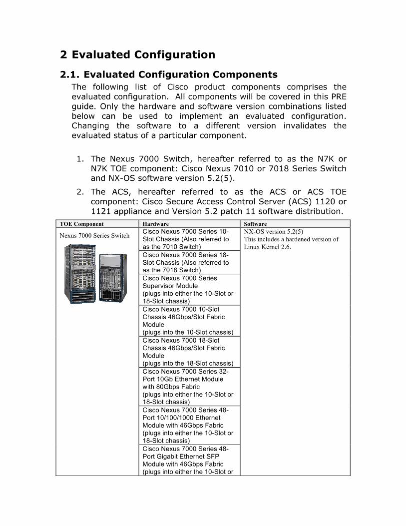
2.1. Evaluated Configuration Components The following list of Cisco product components comprises the evaluated configuration. All components will be covered in this PRE guide. Only the hardware and software version combinations listed below can be used to implement an evaluated configuration. Changing the software to a different version invalidates the evaluated status of a particular component.
1. The Nexus 7000 Switch, hereafter referred to as the N7K or N7K TOE component: Cisco Nexus 7010 or 7018 Series Switch and NX-OS software version 5.2(5).
2. The ACS, hereafter referred to as the ACS or ACS TOE component: Cisco Secure Access Control Server (ACS) 1120 or 1121 appliance and Version 5.2 patch 11 software distribution.
TOE Component Hardware Software
Nexus 7000 Series Switch
Cisco Nexus 7000 Series 10-Slot Chassis (Also referred to as the 7010 Switch)
NX-OS version 5.2(5) This includes a hardened version of Linux Kernel 2.6.
Cisco Nexus 7000 Series 18-Slot Chassis (Also referred to as the 7018 Switch) Cisco Nexus 7000 Series Supervisor Module (plugs into either the 10-Slot or 18-Slot chassis) Cisco Nexus 7000 10-Slot Chassis 46Gbps/Slot Fabric Module (plugs into the 10-Slot chassis) Cisco Nexus 7000 18-Slot Chassis 46Gbps/Slot Fabric Module (plugs into the 18-Slot chassis) Cisco Nexus 7000 Series 32-Port 10Gb Ethernet Module with 80Gbps Fabric (plugs into either the 10-Slot or 18-Slot chassis) Cisco Nexus 7000 Series 48-Port 10/100/1000 Ethernet Module with 46Gbps Fabric (plugs into either the 10-Slot or 18-Slot chassis) Cisco Nexus 7000 Series 48-Port Gigabit Ethernet SFP Module with 46Gbps Fabric (plugs into either the 10-Slot or

TOE Component Hardware Software 18-Slot chassis) Cisco Nexus 7000 Series 8-Port 10Gigabit Ethernet X2 XL Module with 80Gbps Fabric (plugs into either the 10-Slot or 18-Slot chassis) Cisco Nexus 7000 Series 48-Port Gigabit Ethernet XL SFP Module with 46Gbps Fabric (plugs into either the 10-Slot or 18-Slot chassis)
Cisco Secure Access Control Server (ACS)
Cisco CAM25 appliance – 1120 or 1121
ACS Software version 5.2 patch 11 This includes a hardened version of Linux Kernel 2.4.
TOE Component Hardware Software
Nexus 7000 Series Switch
Cisco Nexus 7000 Series 10-Slot Chassis (Also referred to as the 7010 Switch)
NX-OS version 5.2(5) This includes a hardened version of Linux Kernel 2.6.
Cisco Nexus 7000 Series 18-Slot Chassis (Also referred to as the 7018 Switch) Cisco Nexus 7000 Series Supervisor Module Cisco Nexus 7000 10-Slot Chassis 46Gbps/Slot Fabric Module Cisco Nexus 7000 18-Slot Chassis 46Gbps/Slot Fabric Module Cisco Nexus 7000 Series 32-Port 10Gb Ethernet Module with 80Gbps Fabric Cisco Nexus 7000 Series 48-Port 10/100/1000 Ethernet Module with 46Gbps Fabric Cisco Nexus 7000 Series 48-Port Gigabit Ethernet SFP Module with 46Gbps Fabric Cisco Nexus 7000 Series 8-Port 10Gigabit Ethernet X2 XL Module with 80Gbps Fabric Cisco Nexus 7000 Series 48-Port Gigabit Ethernet XL SFP Module with 46Gbps Fabric
Cisco Secure Access Control Server (ACS)
Cisco CAM25 appliance – 1120 or 1121
ACS Software version 5.2 patch 11 This includes a hardened version of Linux Kernel 2.4.
2.2. Excluded Functionality The following functionality has been excluded from the evaluation and must not be used with the TOE:

• Telnet Management
• SNMP Management

3 Acceptance Procedures
3.1. Package Identification and Verification When the customer orders a hardware module it will be delivered by registered delivery using a trusted delivery firm, for example Federal Express. The hardware or module will be packed in a re-sealable bag, within an outer sealed box. The outer box has Cisco Systems on it, the delivery documentation (packing slip) from the delivery firm in a sealed plastic wallet attached to the side, a Cisco sticker showing the shipping details of sender and customer, and a sticker showing the customs information. On the outer box there is also a Cisco sticker showing various barcodes and reference numbers for:
• the packaging ID No.; • customer No.; Product No.; • Serial No.; • Quantity check; • Software No; • sender details and • finally, a Cisco sticker showing a number and barcode for
tracking and distribution.
3.2. Product Identification and Verification Using the packing slip and information on the stickers, the customer recipient must check that the product number and serial numbers on the received hardware match what was ordered. To further ensure proper and secure delivery of the N7K TOE, the recipient must check the models received against the list of TOE component hardware models at the beginning of this PRE wrapper document. Any discrepancies must be immediately reported to Cisco using the contact information on the packing slip.
3.3. Version Identification and Verification In addition to verifying model numbers for hardware components, the software versions must also be verified by the customer recipient. Software versions can be checked by following the “Verification of Software Versions” instruction included in the Common Criteria Specific Operational User Guidance [10]. The version must match what is indicated for the evaluated configuration, as listed in this PRE wrapper and the ST.

4 Installation and Initial Configuration This PRE document is a supplement to the following list of Cisco product documentation. This document makes reference to individual documents as needed by indicating the reference number in brackets (e.g., [6]). The N7K provides a means to configure the N7K settings and the ACS GUI provides a means to configure the ACS component for PRE. In Sections 4.1 and 4.2 below, installation instructions are provided for each of those TOE components individually, up to initial configuration. Then, further PRE instruction for the evaluated configuration is included for each TOE component.
Installation and Configuration Guides are generally included as part of a Cisco product delivery. Since there are several TOE components in this evaluation, it may be necessary for an administrator to seek out additional documents listed below as part of PRE. The documents listed below are specific to the evaluated configuration of the TOE. When creating the evaluated configuration of the TOE, the administrator must verify that they are using the correct guide for the correct version of each TOE component. The documents listed below are available at www.cisco.com.
[1] Cisco Nexus 7000 Series Hardware Installation and Reference Guide September 17, 2010 (Text Part Number: OL-23069-02)
[2] Cisco Nexus 7000 Series NX-OS Software Upgrade and Downgrade Guide, Release 5.x 04/01/2010 (Text Part Number: OL-19605-01)
[3] Cisco Nexus 7000 Series Connectivity Management Processor Configuration Guide May 2010 (Text Part Number: OL-16369-03)
[4] Cisco Nexus 7000 Series NX-OS Fundamentals Configuration Guide, Release 5.x, March 31, 2010 (Text Part Number: OL-19602-01)
[5] Cisco Nexus 7000 Series NX-OS System Management Configuration Guide, Release 5.x July 2010 (Text Part Number: OL-20086-01)
[6] Cisco Nexus 7000 Series NX-OS Security Configuration Guide, Release 5.x March 15, 2010 (Text Part Number: OL-19596-01)
[7] Cisco Nexus 7000 Series Site Preparation Guide

September17, 2010 (Text Part Number: OL-23070-02)
[8] Installation and Upgrade Guide for the Cisco Secure Access Control System 5.2 December 2008 (Text Part Number: OL-21574-01)
[9] User Guide for the Cisco Secure Access Control System 5.2 (Text Part Number: OL-21572-01)
[10] Nexus 7000 Series Switch Operational User Guidance (Common Criteria Specific), Version 0.3 September 2010 (EDCS-763642)
[11] License and Documentation Guide for the Cisco Secure Access Control System, Release 5.2 (Document Number 78-19499-01)
4.1. Install and Configure the N7K Switch
4.1.1. Preparation prior to Installing the N7K Prior to installing the N7K follow the required site preparations in [7]. This document describes the environmental considerations such as airflow, power, humidity, and cabinet sizes that must be considered prior to placing and installing the product.
4.1.2. Connecting the N7K Switch See “Connecting the Cisco Nexus 7000 Switch to the Network” from section Chapter 5 of Error! Reference source not found.. Follow these directions for connecting all N7K models. The instructions for connecting to the console are necessary prior to moving to the following sections.
4.1.3. Running the Setup Utility For an un-configured N7K the setup utility will automatically run at initial startup of the switch from the CLI console. To run the setup utility once a switch has already been configured simply execute the “setup” command at the CLI. For initial setup follow the directions “Setting Up Your Cisco NX-OS Device” from Chapter 3, page 19 of [4]. Follow the steps 1-25 of the setup utility. You may accept the defaults for all steps 1-25 except for the following: For Step 2 Enable password-strength checking and then in Step 3 Choose a strong password according to the guidelines below.
Characteristics of Strong Passwords A strong password has the following characteristics:
•At least eight characters long •Does not contain many consecutive characters (such as “abcd”) •Does not contain many repeating characters (such as “aaabbb”) •Does not contain dictionary words •Does not contain proper names •Contains both uppercase and lowercase characters •Contains numbers
For Step 6 Do NOT configure the SNMP community string. SNMP management is not allowed in the TOE. For Step 11 Configure advanced IP options such as the static routes, default network, DNS, and domain name is optional Example: Configure Advanced IP options (yes/no)? [n]: no Note: No is the default here. However, if you choose not to configure the advanced IP options you will skip steps 12-15. For Step 16 Telnet service. Ensure that the telnet service is NOT enabled by changing the selection to no. Example: Enable the telnet service? (yes/no) [y]: no For Step 17 Enable the SSH service by entering yes. You can then enter the key type and number of key bits. For more information, see “SSH Server Keys” from [6] page 148. RSA keys of 1024 bits or greater must be used. Example: Enable the ssh service? (yes/no) [y]: yes Type of ssh key you would like to generate (dsa/rsa) : rsa Number of key bits <768-2048> : 1024 (or higher)
4.1.4. Configuring the CMP In addition to the console port and management interface each supervisor module also has a connectivity management processor which can be used to manage the N7K in the event the supervisor management port becomes unresponsive. Follow the instructions in “Configuring the CMP” from [3] page 2-2 to configure the cmp.

4.1.5. Upgrading the N7K to the evaluated configuration version 5.2(5)
If the N7K is not at NX-OS 5.2(5) follow the instructions in [2] to upgrade the switch to NX-OS 5.2(5).
4.1.6. Enabling the evaluated configuration security features and settings
From the CLI execute the “show role features” command to see which features are configurable by the network-admin role. By default all features are initially disabled. To see which features are enabled/disabled run the “show features” command. In order to enable a feature simply execute the feature command followed by the feature name. For example “feature netflow”. The following security features must be set as specified for secure operation of the TOE:
4.1.6.1. 802.1X The TOE requires the 802.1X feature to be enabled for use by Cisco TrustSec. This is done with the feature dot1x command in the section referenced for Cisco TrustSec below.
4.1.6.2. Cisco TrustSec (CTS) The TOE requires the Cisco TrustSec feature to be enabled. This is done with the feature cts command. If the ACS server has never been installed, skip to Section 4.2 and follow the installation instructions there prior to CTS configuration on the Nexus switch. See “Configuring Cisco TrustSec” from [6] pages 362-393 for full instructions once ACS has been installed.
4.1.6.3. NAC The TOE requires Extensible Authentication Protocol over User Datagram Protocol (EAPoUDP) to be enabled. This is done with the feature eou command. Once enabled, see “Configuring NAC” from [6] on pages 245-255.
4.1.6.4. SSH The TOE requires the Secure Shell (SSH) server for each virtual device context (VDC) to be enabled. This is done with the feature ssh command. Each VDC can have its own separate ssh server configured. The SSH setting is configured during the initial setup. To change the ssh configuration see “Configuring SSH” from [6] on page 148.
4.1.6.5. Port Security The TOE requires the port security feature globally to be enabled. This is done with the feature port-security command. Once enabled, see “Configuring Port Security” from [6] on page 478 to set up port security on exposed Layer 2 physical interfaces and Layer 2 port-channel interfaces so that they allow inbound traffic from only a restricted set of MAC addresses. These addresses can be learned via static, dynamic, or sticky methods as defined in “Secure MAC Address Learning” from [6] pages 470-471.
4.1.6.6. DHCP Snooping The TOE requires the DHCP snooping feature on the device to be enabled globally. This is done with the feature dhcp command. Once enabled, configure dhcp snooping on at least one VLAN that receives DHCP traffic by referencing “Configuring DHCP Snooping” from [6] page 501 and following.
4.1.6.7. TACACS+ The TOE requires TACACS+ to be enabled. This is done with the feature tacacs+ command. Once enabled, configure TACACS+ from [6] beginning on page 79 “Configuring TACACS+”.
4.1.6.8. IP ACLs and Tunnel Interfaces The TOE requires the creation of tunnel interfaces. This is done with the feature tunnel command in global configuration mode. You can apply IP ACL’s to tunnel interfaces. See “Applying an IP ACL as a Router ACL” from [6] on page 427. MAC ACLs, VLAN ACLs (VACLs), and additional Layer 3 IP ACLs can also be configured on the TOE. These topics are covered in Sections 14, 15, and 13 of [6] respectively. For more information on the types of ACLS and their applications, see the table from [6] on pages 408-409.

4.1.6.9. Telnet (Disable) The TOE requires telnet to be disabled: To disable the Telnet server for a virtual device context (VDC), use the no feature telnet command.
4.1.6.10. IP Source Guard The TOE requires IP Source Guard on Layer 2 interfaces that are not trusted by DHCP snooping. IP Source Guard supports interfaces that are configured to operate in access mode and trunk mode. [Insert command to determine these interfaces here.] To configure IP Source Guard see [6] page 547 “Configuring IP Source Guard”.
4.1.6.11. Traffic Storm Control The TOE requires configuration of a traffic storm control level to prevent disruptions on Layer 2 ports by a broadcast, multicast, or unknown unicast traffic storm on physical interfaces. To set the control level see [6] page 566 “Configuring Traffic Storm Control”.
4.1.6.12. Control Plane Policing The TOE requires configuration of control plane policing to prevent denial-of-service (DoS) attacks from impacting performance. A default CoPP Policy is configured during the initial setup. To change the CoPP Policy see [6] page 589 “Configuring CoPP”.
4.1.6.13. Rate Limiting The TOE provides for configuration of rate limits in packets per second for the following types of redirected packets:
• Access list logging packets • Data and control packets copied to the supervisor module • Layer 2 storm control packets • Layer 2 port security packets • Layer 3 glean packets • Layer 3 maximum transmission unit (MTU) check failure packets • Layer 3 multicast directly connected packets • Layer 3 multicast local group packets • Layer 3 multicast Reverse Path Forwarding (RPF) leak packets • Layer 3 Time-to-Live (TTL) check failure packets • Receive packets
To configure rate limits for particular types of packets see [6] page 608 “Configuring Rate Limits”.
4.1.6.14. SNMP The TOE does not allow for management using SNMP. SNMP is not to be enabled on the TOE.
4.1.7. Optional configuration items The following items may be configured as desired on the TOE:
4.1.7.1. NTP An external time server may be used to provide time data for the TOE. To configure this functionality see “Configuring NTP” from [5] starting on page 3-4. It is a good idea to also follow the instructions on “Configuring the NTP Source Interface” on page 3-11 to lock down the NTP server communications to a specific interface.
4.1.7.2. Logging Settings By default, system messages are logged both to the console and to the file log:messages. To change logging settings see “Configuring System Message Logging” from [5] starting on page 5-3.
4.2. Install and Configure the ACS Server
4.2.1. ACS 5.2 patch 11 Installation For step by step instructions on installation and configuration of the ACS 5.2 patch 11 server see [8]:
1. Begin with [8] page 3-1 “Preparing to Install the Cisco 1121 Secure Access Control System Hardware” and then proceed with page 4-1 “Installing the Cisco 1121 Secure Access Control System Hardware”.
2. Follow the instructions in [8] starting on page 5-2 “Installing the ACS Server” to run the setup and verify the installation. Ensure that the output of the ‘show application version acs’ command (as included on page 5-4) is Version 5.2. If it is not, follow the instructions in [9] starting on page 2-3 “Migrating from ACS 4.x to ACS 5.2”
Note: During this setup process, a CLI administrator user account, also known as an Admin account, is created. This will become the default admin account for accessing the CLI the first time.

3. Follow the instructions in [8] starting on page 7-14 “Applying ACS Patch” to download and install the patch 11 file (5-2-0-26-11.tar.gpg). After patch installation, ensure that the output of the ‘show application version acs’ command (as included on page 5-4) is Version 5.2 patch 11.
4. Follow the instructions in [11] and [9] starting on page 18-33 “Licensing Overview” to procure and install the license on the ACS Server.
4.2.2. Logging in to the web interface The ACS may be administered via an HTTPS-enabled web browser. For details on how to connect to the web interface see instructions starting in [8] on page 8-3 “Accessing the Web Interface”
4.2.3. Creation of ACS Administrators The ACS supports multiple admin levels in the TOE. To create the additional roles see the instructions in [9] on page 16-2 ”Understanding Administrator Roles and Accounts”.
4.2.4. Creation of Nexus Administrators The Nexus Administrators may be authenticated to the TOE either against a database local to the Nexus 7000 appliance or via the RADIUS or TACACS+ services of the ACS. For details on setting up Nexus roles within ACS see instructions starting in [9] on page 8-4 “Managing Internal Identity Stores”. Users can either be imported using the instructions in “Viewing and Importing Users to Internal Identity Stores” or entered manually using the instructions in “Creating Internal Users” both of which begin on page 8-11.
4.2.5. ACS and Cisco TrustSec (CTS) For details on setting up ACS with Cisco TrustSec see instructions starting in [9] on page 4-23 The instructions in the following sections must be followed to correctly and completely configure ACS on the TOE.
4.2.5.1. Adding the N7K or an Endpoint CTS Device To add the N7K as a seed CTS device or add an endpoint AAA client see [9] page 4-24 “Adding Devices for TrustSec”.

4.2.5.2. Creating Security Groups Security Groups are used to separate the devices on the CTS network into logical groups. The TOE supports one or more security groups. First, the administrator must determine the access needs for each device on the network. Devices with the same functionality and access needs can be incorporated into a security group. To setup Security Groups in ACS see [9] starting on page 4-24 “Creating Security Groups”.
4.2.5.3. Setting SGACLs (also known as RBACLs) SGACLs are required for TrustSec network devices. They specify the access policies to be applied to the TOE. To setup SGACLs in ACS see [9] instructions starting on page 4-25 “Creating SGACLs” and continuing to 9-32 “Configuring Security Group Access Control Lists”. Note: A closing ACL (Permit IP or Deny IP) can be used to set the default filter for any unmatched traffic at the end of the ACL. This closing ACL needs to be included in the SGACL itself. Use DenyIP as the closing ACL; otherwise, all traffic will be permitted by default.
4.2.5.4. Configuring a Network Device Admission Control (NDAC) Policy
The NDAC policy defines which security group is sent to a device. To configure an NDAC policy for a device see [9] page 4-25 “Configuring a Network Device Admission Control (NDAC) Policy”.
4.2.5.5. Configuring EAP-FAST Settings for TrustSec EAP-FAST settings must be configured on the ACS in order to correctly communicate with the Nexus TOE component. To configure EAP-FAST settings see [9] page 4-26 “Configuring EAP-FAST Settings for TrustSec”.
4.2.5.6. Creating an Access Service for TrustSec Access Service settings must be configured on the ACS in order to correctly communicate with the endpoint client devices. To configure access service settings see [9] page 4-26 “Creating an Access Service for TrustSec”.
4.2.5.7. Creating an Endpoint Admission Control Policy An Endpoint Admission Control Policy must be applied once access service settings have been configured on the ACS in order to assign a security group type and an authorization profile to the endpoint client

devices. To add a session authorization policy see [9] page 4-27 “Creating an Endpoint Admission Control Policy”.
4.2.5.8. Create an Egress Policy The egress policy (sometimes called SGACL policy) determines which SGACL to apply at the egress points of the network based on the source and destination SGT. To configure egress policy settings see [9] page 4-27 “Creating an Egress Policy”.
4.2.5.9. Creating a Default Policy After configuration of the egress policies for the source and destination SG in the egress matrix, Cisco recommends that you configure the Default Egress Policy. The default policy refers to devices that have not been assigned an SGT. The default policy is added by the network devices to the specific policies defined in the cells. The initial setting for the default policy is Permit All, but in the evaluated configuration this policy should be set to Deny All. To configure the default policy settings see [9] page 4-28 “Creating a Default Policy”.