cisco intelligent automation for cloud installation guide, 4 · cisco intelligent automation for...
TRANSCRIPT
Cisco Intelligent Automation for Cloud 4.3 Installation Guide
Release 4.3 Published: November 13, 2015
Cisco Systems, Inc. www.cisco.com

ii
Cisco Intelligent Automation for Cloud 4.3 Installation Guide
Release 4.3 Published: November 13, 2015
THE SPECIFICATIONS AND INFORMATION REGARDING THE PRODUCTS IN THIS MANUAL ARE SUBJECT TO CHANGE WITHOUT NOTICE. ALL STATEMENTS, INFORMATION, AND RECOMMENDATIONS IN THIS MANUAL ARE BELIEVED TO BE ACCURATE BUT ARE PRESENTED WITHOUT WARRANTY OF ANY KIND, EXPRESS OR IMPLIED. USERS MUST TAKE FULL RESPONSIBILITY FOR THEIR APPLICATION OF ANY PRODUCTS.
THE SOFTWARE LICENSE AND LIMITED WARRANTY FOR THE ACCOMPANYING PRODUCT ARE SET FORTH IN THE INFORMATION PACKET THAT SHIPPED WITH THE PRODUCT AND ARE INCORPORATED HEREIN BY THIS REFERENCE. IF YOU ARE UNABLE TO LOCATE THE SOFTWARE LICENSE OR LIMITED WARRANTY, CONTACT YOUR CISCO REPRESENTATIVE FOR A COPY.
The Cisco implementation of TCP header compression is an adaptation of a program developed by the University of California, Berkeley (UCB) as part of UCB’s public domain version of the UNIX operating system. All rights reserved. Copyright © 1981, Regents of the University of California.
NOTWITHSTANDING ANY OTHER WARRANTY HEREIN, ALL DOCUMENT FILES AND SOFTWARE OF THESE SUPPLIERS ARE PROVIDED “AS IS” WITH ALL FAULTS. CISCO AND THE ABOVE-NAMED SUPPLIERS DISCLAIM ALL WARRANTIES, EXPRESSED OR IMPLIED, INCLUDING, WITHOUT LIMITATION, THOSE OF MERCHANTABILITY, FITNESS FOR A PARTICULAR PURPOSE AND NONINFRINGEMENT OR ARISING FROM A COURSE OF DEALING, USAGE, OR TRADE PRACTICE.
IN NO EVENT SHALL CISCO OR ITS SUPPLIERS BE LIABLE FOR ANY INDIRECT, SPECIAL, CONSEQUENTIAL, OR INCIDENTAL DAMAGES, INCLUDING, WITHOUT LIMITATION, LOST PROFITS OR LOSS OR DAMAGE TO DATA ARISING OUT OF THE USE OR INABILITY TO USE THIS MANUAL, EVEN IF CISCO OR ITS SUPPLIERS HAVE BEEN ADVISED OF THE POSSIBILITY OF SUCH DAMAGES.
Cisco and the Cisco logo are trademarks or registered trademarks of Cisco and/or its affiliates in the U.S. and other countries. To view a list of Cisco trademarks, go to this URL: www.cisco.com/go/trademarks. Third-party trademarks mentioned are the property of their respective owners. The use of the word partner does not imply a partnership relationship between Cisco and any other company. (1110R)
Any Internet Protocol (IP) addresses and phone numbers used in this document are not intended to be actual addresses and phone numbers. Any examples, command display output, network topology diagrams, and other figures included in the document are shown for illustrative purposes only. Any use of actual IP addresses or phone numbers in illustrative content is unintentional and coincidental.
Cisco Intelligent Automation for Cloud 4.3 Installation Guide © 2015 Cisco Systems, Inc. All rights reserved.
Text Part Number:
1
Cisco Systems, Inc. www.cisco.com

Release 4.3 Published: November 13, 2015
2
Ensuring Required Prerequisites Are Ready-to-Go
Successful installation of Cisco IAC 4.3 requires that certain hardware and software prerequisites be in place before you start the install process.
Cisco IAC ComponentsThe major functional components for deployment of Cisco Intelligent Automation for Cloud 4.3 include:
Cisco Prime Service Catalog (PSC)
Cisco Process Orchestrator (PO)
Cisco IAC Virtual Appliance (VA)
Platform ElementsNote: For the complete list of interoperable components and version/release information for the items below, see the Cisco Intelligent Automation for Cloud 4.3 Compatibility & Requirements Matrix located here: http://www.cisco.com/c/en/us/support/cloud-systems-management/intelligent-automation-cloud/tsd-products-support-series-home.html.
Amazon EC2
Chef Server - See Configuring Chef for Cisco IAC Integration, page 23, for more information.
Cisco Application Policy Infrastructure Controller (Cisco APIC)
Cisco Prime Performance Manager (PPM)
Cisco UCS Director
Cisco UCS Manager
OpenStack - See Configuring OpenStack, page 11, for more information.
Puppet Labs’ Puppet Master - See Configuring Puppet Labs for Cisco IAC Integration, page 15, for more information.
VMware vCenter
VMware vCloud Director
About Cisco APICCisco Application Policy Infrastructure Controller (Cisco APIC) supports the deployment, management, and monitoring of any application anywhere, with a unified operations model for the physical and virtual components of the infrastructure. The APIC programmatically automates network provisioning and control that is based on the application requirements and policies.
3
Cisco Systems, Inc. www.cisco.com
Ensuring Required Prerequisites Are Ready-to-Go
Checking Required Prerequisites
Cisco IAC 4.3 integrates with APIC using the Cisco APIC driver installed in OpenStack Neutron as an ML2 plug-in and also APIC Northbound API. The goal is to create network policies in APIC that will automatically configure network communication between IAC networks in the Cisco ACI (Application Centric Infrastructure) fabric. For more information, see the Cisco APIC REST API User Guide, especially the section, “Overview of the APIC REST API” here:
http://www.cisco.com/c/en/us/td/docs/switches/datacenter/aci/apic/sw/1-x/api/rest/b_APIC_RESTful_API_User_Guide/b_IFC_RESTful_API_User_Guide_chapter_01.html
Checking Required PrerequisitesRequired prerequisite components for Windows installations include but are not limited to:
Microsoft IIS
Microsoft .NET framework
Note: Be sure to enable Microsoft IIS before installing .NET framework. This will automatically register ASP.NET with Microsoft IIS.
Oracle and/or Microsoft SQL Server database
Linux O/S for non-Windows installations
Java Runtime Environment (JRE)
WildFly application server
A web browser: Microsoft Internet Explorer, Mozilla Firefox, or Google Chrome
PSExec (ensure that version 2.11 or greater is present on Cisco Process Orchestrator)
Note: Check that these components are installed, configured, and running in the supported versions (see theCisco Intelligent Automation for Cloud 4.3 Compatibility & Requirements Matrix located here: http://www.cisco.com/c/en/us/support/cloud-systems-management/intelligent-automation-cloud/tsd-products-support-series-home.html for details) before you begin the Cisco Intelligent Automation for Cloud installation process.
Note: See Solution Prerequisites Checklists, page 99 for more details.
Note: Refer to the installation guides for each component product for complete information on how to install and configure the associated software; for example, see the Cisco Process Orchestrator guides for complete information on Cisco Process Orchestrator.
Note: DBAs commonly have a convention or security policy requiring a user-naming scheme. Note that you will most likely not be able to set the username of the service account according to your practices with Cisco IAC 4.3.
Note: PSExec should be installed on the Cisco Process Orchestrator server for Application Configuration Management. Place PSExec onto your executable path for installing applications on a Windows Server.
Setting Up Your NetworksFirst, choose a network type to determine how this network can be used:
User networks are used for deploying virtual machines.
Management networks are used for management access to cloud servers.
Infrastructure networks are used for management interfaces of Hypervisor hosts and other infrastructure devices.
Then, prepare your networks to include the following requirements:
4
Ensuring Required Prerequisites Are Ready-to-Go
Preparing Storage Management
At least one VLAN to use as a destination network for provisioning servers. You can define a destination network as a community, user, or management network when you create the network in Prime Service Catalog.
— User networks are assigned to specific Virtual Data Centers owned by an organization.
— Management infrastructure within the cloud system may be used to manage cloud servers, for example, for remote access and monitoring.
Preparing Storage ManagementPrepare your storage management system using the following information:
Install and configure Storage Area Network (SAN) storage or iSCSI storage required for Distributed Resource Scheduler (DRS) clusters. For iSCSI or Network File System (NFS) storage solutions, VMware supports Dynamic Host Configuration Protocol (DHCP.) It is important that any of these solutions use DHCP, otherwise static IP information, wherever it is applicable, will have to be configured manually after the automated process is complete.
Create the storage volumes that will be used for datastores and datastore clusters.
Configure Logical Unit Number (LUN) access in your storage management system and assign World Wide Node Name (WWN) pools (see “Setting Up Cisco UCS Manager Pools” on page 5)
vCenter datastores map to or reference specific LUNs. These mappings will replicate to a new host if the host blade has been given the same LUN access as all the other hosts in the cluster. This is accomplished through WWN pools.
LUN configuration can be assigned to any WWN that is within a specific range. For a new host to be assigned WWNs that are within that range, ensure that it is coming from the pre-defined pool. Whenever a service profile is created from a service profile template for a blade, specify that the template generate WWN assignments from a specific pre-defined pool in Cisco UCS Manager. Datastore access should automatically be in sync with all the other hosts in that cluster when the service profile template is used to provision the blade.
Preparing Cisco UCS and Bare Metal Operating System Provisioning
Setting Up Cisco UCS ManagerWhile Cisco UCS Manager is an optional component, should your cloud deployment include this technology, Cisco UCS Manager should be installed and configured before installing Cisco IAC 4.3. For instructions on installing and configuring the application, see the Cisco UCS Manager documentation on cisco.com.
Setting Up Cisco UCS Manager PoolsCisco UCS Manager utilizes different types of pools to control assignment of unique identifiers (such as UUIDs, MACs and WWNs) to blade servers. These pools must be created and assigned to Service Profiles. You need to create the following pools:
Universal Unique Identifier (UUID) Suffix Pool—Used to uniquely identify each blade server.
Media Access Control (MAC) Address Pool—Used to assign a unique MAC address to each vNIC assigned to a blade.
WWNN (World Wide Node Name) Pool—Assigned to a node in a Fibre Channel fabric, and used to assign unique WWNNs to each blade in a range that will allow appropriate LUN access
WWPN (World Wide Port Names) Pool—Assigned to specific ports in a Fibre Channel fabric, and used to assign unique WWPNs to each blade in a range that will allow appropriate LUN access
For instructions on creating the pools, see the Cisco UCS Manager documentation on cisco.com.
5
Ensuring Required Prerequisites Are Ready-to-Go
Preparing Cisco UCS and Bare Metal Operating System Provisioning
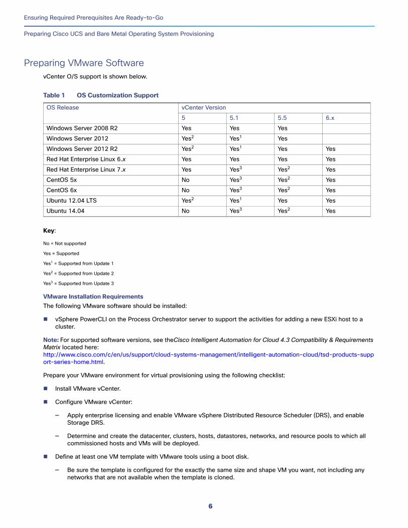
Preparing VMware SoftwarevCenter O/S support is shown below.
Key:
No = Not supported
Yes = Supported
Yes1 = Supported from Update 1
Yes2 = Supported from Update 2
Yes3 = Supported from Update 3
VMware Installation RequirementsThe following VMware software should be installed:
vSphere PowerCLI on the Process Orchestrator server to support the activities for adding a new ESXi host to a cluster.
Note: For supported software versions, see theCisco Intelligent Automation for Cloud 4.3 Compatibility & Requirements Matrix located here: http://www.cisco.com/c/en/us/support/cloud-systems-management/intelligent-automation-cloud/tsd-products-support-series-home.html.
Prepare your VMware environment for virtual provisioning using the following checklist:
Install VMware vCenter.
Configure VMware vCenter:
— Apply enterprise licensing and enable VMware vSphere Distributed Resource Scheduler (DRS), and enable Storage DRS.
— Determine and create the datacenter, clusters, hosts, datastores, networks, and resource pools to which all commissioned hosts and VMs will be deployed.
Define at least one VM template with VMware tools using a boot disk.
— Be sure the template is configured for the exactly the same size and shape VM you want, not including any networks that are not available when the template is cloned.
Table 1 OS Customization Support
OS Release vCenter Version
5 5.1 5.5 6.x
Windows Server 2008 R2 Yes Yes Yes
Windows Server 2012 Yes2 Yes1 Yes
Windows Server 2012 R2 Yes2 Yes1 Yes Yes
Red Hat Enterprise Linux 6.x Yes Yes Yes Yes
Red Hat Enterprise Linux 7.x Yes Yes3 Yes2 Yes
CentOS 5x No Yes3 Yes2 Yes
CentOS 6x No Yes3 Yes2 Yes
Ubuntu 12.04 LTS Yes2 Yes1 Yes Yes
Ubuntu 14.04 No Yes3 Yes2 Yes
6
Ensuring Required Prerequisites Are Ready-to-Go
Important Note Regarding Cisco Prime Service Catalog Installation
— If several different configurations are desired, they should be controlled by supplying a unique template for each configuration.
Provisioned hosts will have evaluation licensing only. You will need to add licensing manually in the vSphere Client.
Note: For information about installing and configuring your VMware environment, see the ESX and vCenter Server Installation Guide 4.0.
Note: Users must have the ability to create resource pools. In addition, resource pools must be enabled on VMware VCenter.
Note: Forward slashes in vCenter object names break the parsing process. If any of your vCenter object names contain forward slashes, rename the files before you specify a vCenter path.
Important Note Regarding Cisco Prime Service Catalog InstallationDuring the Prime Service Catalog installation process, you are presented with a checkbox to install storefront content. Do not check this box (leave it unchecked).
Important Note Regarding SRM and vCenterCisco IAC 4.3 only supports VMware Site Recovery Manager (SRM) with storage replication and standby vCenter, so the VM ID does not change.
7

Ensuring Required Prerequisites Are Ready-to-Go
Important Note Regarding SRM and vCenter
8
Installing and Configuring Optional Software
This chapter covers optional software that can be used with Cisco IAC 4.3. Note that this chapter provides only product names. For version numbers, see the Cisco Intelligent Automation for Cloud Product Compatibility Matrix. Optional software includes but is not limited to:
Cisco Software, including:
— Cisco Application Policy Infrastructure Controller (Cisco APIC) and the APIC plugin for OpenStack (see Configuring OpenStack, page 11)
— Cisco Group-Based Policy (GBP) driver for the APIC plugin
— Cisco IAC Management Appliance
— Cisco UCS Director
— Cisco UCS Manager
VMware, including:
— vCenter
— vCloud Director
— ESXi
— vSphere
— vSphere PowerCLI
Microsoft Active Directory and other LDAP servers
Amazon EC2
Additional Optional SoftwareCisco IAC also offers support for the following software, each of which is covered in its own section.
Chef Server - See Configuring Chef for Cisco IAC Integration, page 23.
Puppet Labs’ Puppet Master - See Configuring Puppet Labs for Cisco IAC Integration, page 15.
OpenStack - See Configuring OpenStack, page 11.
9
Cisco Systems, Inc. www.cisco.com
Installing and Configuring Optional Software
Understanding Cisco UCS Director
Understanding Cisco UCS DirectorCisco UCS Director delivers unified management for industry-leading converged infrastructure solutions based on Cisco Unified Computing System (UCS) and Cisco Nexus technologies. UCS Director is a higher-level manager over multiple UCS Managers. For instructions on installing and configuring Cisco UCS Director, see Cisco UCS Director documentation on Cisco.com.
Understanding Cisco UCS ManagerCisco Unified Computing System (UCS) Manager provides unified, embedded management of all software and hardware components in the Cisco UCS. It controls multiple chassis and manages resources for thousands of virtual machines. For instructions on installing and configuring Cisco UCS Manager, see Cisco UCS Manager documentation on Cisco.com.
Preparing the Directory and Mail Server via LDAP and SMTPTo prepare your directory and e-mail environment, ensure that the following conditions are met:
LDAP server software, such as Microsoft Active Directory, is installed and configured.
SMTP server is installed and configured with an account to send and receive e-mails.
Note: For information on configuring the STMP server, see the Cisco Process Orchestrator Installation and Administration Guide or the Cisco Cisco Prime Service Catalog Installation Guide.
Understanding Amazon EC2Amazon EC2 is a Web-based service that allows business subscribers to run application programs in the Amazon.com computing environment. The EC2 can serve as a practically unlimited set of virtual machines. For more about Amazon EC2, see the Amazon EC2 website at http://aws.amazon.com/ec2/.
10
Configuring OpenStackCisco Intelligent Automation for Cloud 4.3 supports three types of OpenStack deployment:
Standard openstack.org deployment, which allows for private networks (that is, networks under a project). These are created with GRE overlay network transports, from compute to the network node.
CIsco APIC-enabled OpenStack with private networks of type “VLAN.” With this scenario, Cisco IAC Network POD and associated orchestration services and workflows identify and maintain consistent VLAN assignment and IP addressing.
Cisco Group-Based Policy (GBP) enabled OpenStack. With Cisco IAC 4.3, you can now configure OpenStack networks using application-level policies.
Note: For more information on Cisco APIC and OpenStack, refer to detailed Cisco APIC documentation located here: http://www.cisco.com/c/en/us/td/docs/switches/datacenter/aci/apic/sw/1-x/api/openstack/b_Cisco_APIC_OpenStack_Driver_Install_Guide.html.
OpenStack Versions SupportedCisco IAC 4.3 supports the following versions of OpenStack:
Juno
Kilo
Note that only these versions listed have been implemented and successfully tested here at Cisco. The interoperability of any other version(s) of OpenStack cannot be guaranteed. In addition, the Cisco APIC OpenStack driver and Cisco GBP driver are supported for use with Cisco IAC 4.3 and OpenStack. For implementation information, see the Installing the Cisco APIC OpenStack Driver Guide here:
http://www.cisco.com/c/en/us/td/docs/switches/datacenter/aci/apic/sw/1-x/api/openstack/b_Cisco_APIC_OpenStack_Driver_Install_Guide.html
Required OpenStack ServicesThe following OpenStack services are mandatory for the correct performance of Cisco IAC 4.3:
Block Storage (Cinder)
Compute (Nova)
Identity (Keystone)
Image (Glance)
Networking (Neutron)
Prime Performance Manager (Ceiliometer)
Note: We also recommended installing the OpenStack dashboards included as part of Horizon.
11
Cisco Systems, Inc. www.cisco.com
Configuring OpenStack
OpenStack Configuration Notes1. If you are using all-in-one deployment or a scenario with only one available compute node make sure that you have
set both allow_resize_to_same_host and allow_migrate_to_same_host to true in configuration file at /etc/nova/nova.conf.
Note: These options allow you to resize the instance on one node.
Set resize_confirm_window=x. By default, this is set to 0, but you need to change this to x seconds in order to automatically confirm the resize after x seconds.
2. If you are running OpenStack within a virtual machine set, in order to use QEMU you must set the following options in configuration file on your compute host(s) at /etc/nova/nova.conf:
libvirt_type=qemuCinder service=mandatory
Note: Configuration changes are applied only after the restart of Nova services.
3. If you would like OpenStack to report debugging information into an httpd log file, specify the following parameters in the configuration files found at /etc/openstack-dashboard/local_settings:
DEBUG=TrueTEMPLATE_DEBUG=DEBUG
Note: The file may be a significant size; this may negatively affect performance.
4. Check that you have opened all necessary ports in your firewall:
8776 - Block Storage (cinder)8774 - Compute (nova) endpoints5000 - Identity service public endpoint9696- Networking (neutron)5672 - Message Broker (AMQP traffic)
Note: You can find a list of the recommended ports here: http://docs.openstack.org/trunk/config-reference/content/firewalls-default-ports.html
Note: For the correct steps needed to install the OpenStack solution on your environment, refer to the OpenStack documentation located on the OpenStack website at: http://docs.openstack.org/.
OpenStack Considerations
OpenStack Node BootstrappingDuring node bootstrapping, the following node attributes are automatically assigned:
stack_instance: Name of the Stack Instance (shared by all servers in the same stack)
iac_organization: Name of the IAC organization (including tenant prefix) for customer who ordered the stack
Bootstrapping of ACM roles onto OpenStack InstancesThe Linux Bootstrapping credentials input for the Chef or Puppet Platform Element need to have an OS-specific username depending on the template being used. For example, if the version of Linux being used is Ubuntu, the username should be “ubuntu”; if using CentOS, the username will be “centos”. If the business is using multiple OS types, the platform element will need to be updated prior to deploying a different os type. The key-pair to these accounts will be set by IAC during the instance creation and therefore be used by the ACM bootstrapping process later on.
12
Configuring OpenStack
Note: Keypair is presently the only option available if the user wants to bootstrap ACM roles onto an OpenStack Linux instance.
Important: To use password SSH authentication instead of key-pairs, configure images to have a generic user and password built in. After creating the instance, log into the console using the generic account and manually change the SSH daemon to allow for password authentication option. With this done, ACM bootstrapping is not possible using password authentication. However, after making the above changes, brownfielding ACM roles is possible using the username and password account.
OpenStack Physical Network Name, GV OpenStack.Configuration.PhysicalNetworkNameFor OpenStack with the Cisco APIC plugin, Cisco IAC 4.3 supports deployment with a Physical Network name configured under the ML2 plugin with value of “physnet1” — a common usage for a Network name but one that is a free-form name. You may choose to use another. Cisco IAC provides a Global Variable (OpenStack.Configuration.PhysicalNetworkName) to change this.
Note: For more information on Cisco APIC and OpenStack, refer to detailed APIC documentation located here: http://www.cisco.com/c/en/us/td/docs/switches/datacenter/aci/apic/sw/1-x/api/openstack/b_Cisco_APIC_OpenStack_Driver_Install_Guide.html.
13

Configuring OpenStack
14
Configuring Puppet Labs for Cisco IAC Integration
Puppet Labs software must be licensed and in place for use with Cisco Intelligent Automation for Cloud 4.3. For POCs, PE is available for free to manage up to 10 nodes.
Note: Cisco IAC 4.3 supports Puppet Labs 3.8.x. We recommend 3.8.2. Later versions of Puppet, as well as the FOSS (Open Source) version, are not supported.
For Puppet, the following services are included:
Register Puppet Role
Update Puppet Infrastructure Item
Activate Puppet Resource
Note: An active Internet connection to the Puppet clients is required to properly install new applications.
Basic Puppet ConsiderationsTo leverage integration with Puppet with Cisco IAC, Puppet modules need to be designed to expose roles and profiles. Node classification is accomplished via Hiera, so the site.pp file for each environment must include the following:
node default { hiera_include('classes')}
Your main hiera.yaml file should look something like the following:
---:backends:- yaml!
:yaml::datadir: /etc/puppetlabs/puppet/environments/%{environment}/hieradata
:hierarchy:- "nodes/%{fqdn}"- common
Be advised that when you create a Puppet connection from System Setup, it creates two Process Orchestrator targets, a main Web Service target (for future use) and a reference to a Terminal target (for SSH). You should update the terminal target’s default maximum number of concurrent sessions to a number greater than one (preferably 100) to avoid bottlenecks when running Puppet on multiple nodes.
Self-service ordering of servers includes the option to apply a single Puppet role from an environment. Although best practice is to assign a single role to a server, this can be extended further to include multiple roles, or add roles later through an add-on service. This is out of scope for Cisco IAC 4.3, but is available through stack blueprints using the Application Stack Automation Pack (ASAP).
Note: With Cisco IAC 4.3, you can add multiple puppet applications to a single node (VM).
15
Cisco Systems, Inc. www.cisco.com
Configuring Puppet Labs for Cisco IAC Integration
Method for Sharing Facts Between Nodes and Stacks
Puppet is configured via an SSH/PSExec connection to the new node. A well-known root/Administrator (or equivalent) user and password is required for cases where no password is specified in the order. All nodes requiring configuration management should have the same root/Administrator user/password. This can be changed during or post-configuration. Sudo is used for non-root users. The certificate authority for Puppet requires that clocks for master and agent servers be synchronized with a common time source (for example, using the ntpd service).
Note: For vCenter, Cisco IAC automatically configures new Puppet nodes to have VMware Tools synchronize the clock with the ESXi host; therefore, the best way to achieve clock synchronization is to ensure that the ESXi hosts and the Puppet Master use the same time authority to set the time.
If the Puppet master requires a private key file to connect, you will need to specify this with the Connect Cloud Infrastructure or Update Cloud Infrastructure service. Check the Additional Options check box to specify this.
If you need to use an alternative repository for the Puppet Enterprise Installer, you can override the default Puppet Labs location with the Connect Cloud Infrastructure or Update Cloud Infrastructure service. Choose the Additional Options check box to specify a different base URL. The installer files must match the Puppet Labs naming conventions exactly.
You can override the location for the hiera node classification files with the Connect Cloud Infrastructure or Update Cloud Infrastructure service. Choose the Additional Options check box to specify an override. You use $environment as a placeholder in the path. Be sure your hiera.yaml file is modified accordingly.
Method for Sharing Facts Between Nodes and Stacks When using Puppet with the Application Stack Automation Pack (ASAP), it is often necessary for one node in a stack to be able to reference the facts of another (for example, the IP Address). This is achieved by recording the stack instance name and the role in a stack as external facts for each node that can be used as lookup criteria. To query facts about the other nodes in a stack you need to first have installed the prerequisite puppetdbquery module from https://forge.puppetlabs.com/dalen/puppetdbquery.
Facts that Cisco IAC automatically assigns to nodes include:
stack_instance: Name of the Stack Instance (shared by all servers in the same stack)
stack_role: Role Name or List of Role Names (comma-separated) for the server
iac_organization: Name of the IAC organization (including tenant prefix) for customer who ordered the stack
In your puppet code, use the following as an example of retrieving facts about another node in the stack.
$db_host_ip = query_nodes(“stack_instance=‘$stack_instance’ and stack_role~’(,|^)mysql (,|$)’)”
The query above returns the IP address for the node that has the role mysql in the same stack as the current node running this code.
Working With Class Parameter OverridesThe IAC integration with Puppet allows class parameter value overrides to be configured and exposed to users ordering servers. This is done through special JSON files that reside in the same location as your profile module’s puppet code (under manifests). Class override parameters are always defined in the profile module, and, if present, have the same name as profile or profile subclass followed by “.params.json”.
Below is a sample of “webserver.params.json” corresponding to the profile class called “webserver”. For each parameter, you provide a friendly name, description, default value, and most importantly, what class parameter you are overriding. You can alternatively define an externally defined fact for a node by specifying ‘fact’, ‘factor’ or an empty value for the class_param attribute of the parameter.
16
Configuring Puppet Labs for Cisco IAC Integration
Proxies for Puppet
If you provide a comma-separated options list, users will have to choose one of the values in the list. Override values are added to the Hiera node classification file along with the role that includes the profiles requiring these parameter values. Because class parameter overrides are handled in Hiera node classification, be careful of parameter override precedence. Any values provided in a “class” inclusion block, will take precedence over those values provided by Hiera.
Profile Class Parameter Overrides JSON Example{
"id": "profile::webserver", "parameters": { "customer.name": { "display_name": "Customer Name", "description": "The customer name", "help_text": "Please select a valid customer.", "options": "PuppetLabs,Cisco Systems,ACME Bread", "data_type": "string", "validation": "", "value": "PuppetLabs", "required": "yes", "class_param": "myapp::custname" }, "customer.greeting": { "display_name": "Customer Greeting", "description": "Greeting to display to customer.", "help_text": "Please select a customer greeting. For example, Hello.", "options": "", "data_type": "string", "validation": "", "value": "Hello", "required": "yes", "class_param": ”facter" }, "http.port": { "display_name": "HTTP Port", "description": "The HTTP port to use.", "help_text": "Please select an HTTP port for the web page. Default is 80.", "options": "", "data_type": "integer", "validation": "", "value": "99", "required": "no", "class_param": "apache::port"} }
}
Proxies for PuppetTo set up your proxies for Puppet, follow the steps below.
1. Navigate to Setup > System Settings > Connections.
2. Select Connect Cloud Infrastructure if you are setting up the initial connection, or select Update Cloud Infrastructure if you want to go back into your setup and add or change the proxy settings.
Important: When you update settings using the Update Cloud Infrastructure, you must re-enter information (such as passwords) into any field that displays as empty. The reason for this is that the system will overwrite the existing data for that field in the database with blanks. Passwords are not displayed for security / cryptographic reasons.
3. Scroll down and select Show Additional Options.
4. Enter the Installer Package Base URL as needed.
5. Enter the Alternate Module Path information, as needed.
6. Enter the Hiera Node Classification Path, as needed.
7. From the Bootstrap/Proxy info for Operating System, select either Windows or Linux.
Note: You can enter information for both, and Cisco IAC will track it. You can only enter one at a time.
17
Configuring Puppet Labs for Cisco IAC Integration
Proxies for Puppet
8. Enter the proxy (either Windows Proxy or Linux Proxy, as is appropriate.) For example, http://133.133.133.152. Include the port number, if that is how you have set up your environment; for example: http://133.133.133.152:8080.
9. In the Proxy Bypass box, enter one or many exceptions. You can enter them as URLs or as IP addresses. They must be separated by semi-colons (;) or the system will not parse them correctly.
Note: While there is a field for the proxy bypass for Windows, this feature does not actually function. At this time, Windows does not accept a proxy bypass.
10. Enter the Bootstrap User name and the Bootstrap Password.
11. Enter the Private Key, as needed.
12. Click Submit.
Note: Alternatively, if proxies are used in your environment, you can update the following extended target properties as necessary for your Puppet web target in Process Orchestrator:
Puppet.Target.Bootstrap.Linux.Proxy Puppet.Target.Bootstrap.Linux.NoProxy Puppet.Target.Bootstrap.Windows.Proxy Puppet.Target.Bootstrap.Windows.NoProxy
Discovering the New Puppet Role Note: For more detailed information on the forms and navigation used in resource discovery, see Managing Resources Using Discovery, page 19 of the Cisco Intelligent Automation for Cloud Administrator Guide.
1. Start Cisco IAC.
2. Select Setup > Manage Infrastructure.
3. Select Puppet from the left platform elements column.
4. On the Puppet page, click the Discover Puppet Roles option.
5. Click Submit Order.
Verifying that the New Role was Successfully Discovered1. Select Setup > Manage Infrastructure again.
2. Select Puppet from the platform elements in the left-hand column.
3. Review the list of role names and verify that the new role name is in the list and is shown as “Discovered.”
Registering Environment and RolesYou only need to register Roles and Environment. These elements should be displayed with a status of “Discovered.”
1. To register a Role, find your the correct Role that you want to register (it will currently be listed as “Discovered”).
2. Click the gear icon ⚙ next to that Role and then choose Register Role from the popup.
3. On the Puppet Role Registration form, enter:
a. A friendly name
b. An application code; for example:
— iis for Windows
— web (apache) for Linux
18
Configuring Puppet Labs for Cisco IAC Integration
Proxies for Puppet
c. Price
d. Tenant access
e. Operating System: Part of registering role is selecting which platform the role supports. Options are Both, Windows, and Linux. This is a required field.
4. Click Submit.
Note: Register an Environment in the same way.
Ordering a Compute PODNote: For more detailed information on the forms and navigation used in working with PODs, see Managing PODs, page 125 of the Cisco Intelligent Automation for Cloud Administrator Guide.
1. Select Setup > System Settings > PODs.
2. Choose Register a Compute POD.
3. Under the POD Details area, enter a Compute POD Name and an optional Description.
4. Select the location for Cisco Process Orchestrator from the Location drop down.
5. From the Cloud Infrastructure Type drop down, select one of the following twp options from the list:
— OpenStack Platform Element
— VMware vCenter Server
For OpenStack:a. From the Network POD Name drop down, select the Network POD instance that serves in this POD.
b. From the Open Stack Cloud Manager Instance drop down, select the Open Stack Cloud Manager that contains the hosts in this POD.
For VMware:a. From the Network POD Name drop down, select the Network POD instance that serves in this POD.
b. From the VMware vCenter Instance drop down, select the vCenter instance that controls hypervisor hosts in this POD.
c. From the VMware Datacenter drop down, select the vCenter dataoenter that contains the hypervisor hosts in this POD.
d. From the Cisco UCS Manager Instance drop down, select
e. From the Cisco UCS Director Bare metal Agent drop down, select the U08 Manager instance that controls the servers in this POD.
f. From the Provisioning UCS VLAN drop down, select the appropriate provisioning vLAN.
g. From the Provisioning Hypervisor VLAN, , select the appropriate provisioning vLAN.
6. Click Submit Order.
7. Verify that the req has completed successfully in Process Orchestrator.
19
Configuring Puppet Labs for Cisco IAC Integration
Proxies for Puppet
Registering a Service Resource ContainerNote: Instructions given below are specific to the task at hand. For more detailed information on the forms and navigation used in managing containers, see Managing Containers, page 131 of the Cisco Intelligent Automation for Cloud Administrator Guide.
1. On the Modify Service Resource Container form, enter the necessary information.
2. Click Submit Order.
Creating Tenants and OrganizationsNote: Instructions given below are specific to the task at hand. For more detailed information on the forms and navigation used in managing orgs and tenants, see Managing Tenants, page 91 and of the Cisco Intelligent Automation for Cloud Administrator Guide.Managing Organizations and Users, page 65.
Creating the Tenant1. On the Create Tenant form, complete all required fields.
2. Select YES for the following:
a. Create Virtual Data Center
b. Create Virtual Machine From Template
c. Application Configuration Management
3. Click Submit Order.
Creating the OrganizationYou then create an organization under that tenant.
1. On the Create Organizations form, complete all required fields.
2. Select YES for the following:
a. Virtual Machine From Template Ordering
b. Application Configuration Management
c. Virtual Data Center Ordering
3. Select your Service Resource Container.
4. Click Submit Order.
Creating a Network You need to create a network before you proceed with creating a VDC.
Note: For more detailed information on the forms and navigation used in creating networks, see Provisioning and Managing Networks, page 97 of the Cisco Intelligent Automation for Cloud Administrator Guide.
20
Configuring Puppet Labs for Cisco IAC Integration
Proxies for Puppet
Creating and Ordering VDCs
Creating the Virtual Data CenterNote: For more detailed information on the forms and navigation used in creating and managing VDCs, see Managing Servers, Virtual Machines, and Virtual Data Centers, page 103 of the Cisco Intelligent Automation for Cloud Administrator Guide.
1. Go to my VDCs or Order Services and launch Create VDC order form.
2. Select your Tenant.
3. Select your Organization.
4. Click Submit Order.
Ordering VDCsOn the Order VDC Form, complete the following fields:
VDC Details:
— VDC Name
— Domain Name
— POD Name
— Cluster Name
— Datastore Name
— Snapshots Per VM Limit
— CPU Limit (MHz)
Resource Pool Details
— Resource Pool
— CPU Reservation (MHz)
— Memory Reservation (GB)
21

Configuring Puppet Labs for Cisco IAC Integration
Proxies for Puppet
22
Configuring Chef for Cisco IAC IntegrationChef Labs software must be licensed and in place for use with Cisco Intelligent Automation for Cloud 4.3. Hosted or Private Chef 12.0.x or higher is required (with appropriate patches). For Chef, the following services are included:
Register Chef Cookbook
Register Chef Role
Update Chef Infrastructure Item
Activate Chef Resource
Due to Chef recently changing its naming convention for the chef agent installers, we have implemented our own naming conventions for Cisco IAC 4.3 for the local repository. This is the template for those files:
chef-{version}-{distro}-{arch}.rpmchef-{version}-{distro}-{arch}.debchef-windows-{version}.msiFor example:chef-12.0.x-el-5-x86_64.rpmchef-12.0.x-el-6-x86_64.rpmchef-12.0.x-ubuntu-x86_64.debchef-windows-12.0.x.msi
Note: An active Internet connection to the Chef clients is required to properly install new roles.
Note: When registering the Chef master in Cisco IAC 4.3, there is the option to configure a proxy server to enable Internet access be used during role installation. If using the proxy settings, make sure to include both the Chef Master and local repository (if applicable) in the proxy bypass. Additional information on proxies is included below.
Basic Chef ConsiderationsBe advised that when you create a Chef connection from System Setup, it creates two Process Orchestrator targets, a main Web Service target (for future use) with a reference to a Terminal target (for SSH). You should update the terminal target’s default maximum number of concurrent sessions to a number greater than one (preferably 100) to avoid bottlenecks when running Chef on multiple nodes.
Self-service ordering of servers includes the option to apply a single Chef role and environment. Although best practice is to assign a single role to a server, this can be extended further to include multiple roles, or add roles/recipes later through an add-on service. This is currently out of scope for this accelerator kit.
For Linux, Chef is configured via an SSH connection to the new node. A well-known root (or equivalent) user and password is required. All Linux templates requiring configuration management should have the same root user and password. This can be changed during or post-configuration. Sudo support will be added in a later release.
You need to set the two extended target properties of the Chef web target in Cisco Process Orchestrator:
Chef.Target.Bootstrap.Linux.UserChef.Target.Bootstrap.Linux.Password
23
Cisco Systems, Inc. www.cisco.com
Configuring Chef for Cisco IAC Integration
Basic Chef Considerations
Cisco IAC allows users to specify the Administrator user/password, so the above is not required for Windows. The certificate authority for Chef requires that the server and client clocks be synchronized with a common time source (for example, using the ntpd service).
Note: The hosts/controller these VM/instances run on should also be synced to the same time source; such as VMware Hosts, Openstack Controller/Compute Node.
Note: For vCenter, Cisco IAC automatically configures new Chef nodes to have VMware Tools synchronize the clock with the ESXi host; therefore, the best way to achieve clock synchronization is to ensure that the ESXi hosts and the Chef server use the same time authority to set the time.
If the Chef server/workstation you defined with the Connect Cloud Infrastructure service requires a private key file to connect, you will need to create a new Public-Key Authenticated Admin User runtime user definition in Process Orchestrator and replace the Opscode Chef Terminal (SSH) target’s default runtime user.
Note: Connecting via private key is optional, yet recommended.
Integrating the Cisco-Specific RoleIntegration with Cisco IAC requires that the “cisco-cloud-automation” cookbook be uploaded into the Chef repository. The cookbook can be found as a zip file in the kit’s Chef folder and should be extracted to a Chef Workstation and uploaded to the server. To do so, copy the Cisco-Cloud-Automation folder to your Chef Cookbook repository. Later, you will select the available recipe, also called “cisco-cloud-automation.” When you do so, be sure to leave all attributes empty.
Using the Cisco CookbookThe cookbook is required by the CiscoCM role that also must be uploaded from the included CiscoCM.json file. A role on the Chef Server called “ciscocm” (all lowercase) is required. This name can be changed, however. See xxx (below) for information on changing the CiscoCM role name.
Changing the CiscoCM Role Name
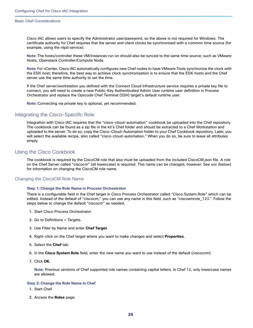
Step 1: Change the Role Name in Process OrchestratorThere is a configurable field in the Chef target in Cisco Process Orchestrator called “Cisco.System.Role” which can be edited. Instead of the default of “ciscocm,” you can use any name in this field, such as “ciscoemrole_123." Follow the steps below to change the default “ciscocm” as needed.
1. Start Cisco Process Orchestrator.
2. Go to Definitions > Targets.
3. Use Filter by Name and enter Chef Target.
4. Right-click on the Chef target where you want to make changes and select Properties.
5. Select the Chef tab.
6. In the Cisco System Role field, enter the new name you want to use instead of the default (ciscocom).
7. Click OK.
Note: Previous versions of Chef supported role names containing capital letters. In Chef 12, only lowercase names are allowed.
Step 2: Change the Role Name in Chef1. Start Chef.
2. Access the Roles page.
24
Configuring Chef for Cisco IAC Integration
Working with Role Attributes Overrides
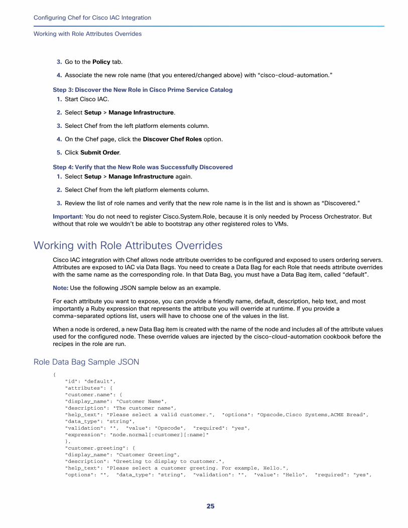
3. Go to the Policy tab.
4. Associate the new role name (that you entered/changed above) with “cisco-cloud-automation.”
Step 3: Discover the New Role in Cisco Prime Service Catalog 1. Start Cisco IAC.
2. Select Setup > Manage Infrastructure.
3. Select Chef from the left platform elements column.
4. On the Chef page, click the Discover Chef Roles option.
5. Click Submit Order.
Step 4: Verify that the New Role was Successfully Discovered1. Select Setup > Manage Infrastructure again.
2. Select Chef from the left platform elements column.
3. Review the list of role names and verify that the new role name is in the list and is shown as “Discovered.”
Important: You do not need to register Cisco.System.Role, because it is only needed by Process Orchestrator. But without that role we wouldn’t be able to bootstrap any other registered roles to VMs.
Working with Role Attributes OverridesCisco IAC integration with Chef allows node attribute overrides to be configured and exposed to users ordering servers. Attributes are exposed to IAC via Data Bags. You need to create a Data Bag for each Role that needs attribute overrides with the same name as the corresponding role. In that Data Bag, you must have a Data Bag item, called “default”.
Note: Use the following JSON sample below as an example.
For each attribute you want to expose, you can provide a friendly name, default, description, help text, and most importantly a Ruby expression that represents the attribute you will override at runtime. If you provide a comma-separated options list, users will have to choose one of the values in the list.
When a node is ordered, a new Data Bag item is created with the name of the node and includes all of the attribute values used for the configured node. These override values are injected by the cisco-cloud-automation cookbook before the recipes in the role are run.
Role Data Bag Sample JSON{
"id": "default", "attributes": { "customer.name": { "display_name": "Customer Name", "description": "The customer name", "help_text": "Please select a valid customer.", "options": ”Opscode,Cisco Systems,ACME Bread", "data_type": "string", "validation": "", "value": "Opscode", "required": "yes", "expression": "node.normal[:customer][:name]" }, "customer.greeting": { "display_name": "Customer Greeting", "description": "Greeting to display to customer.", "help_text": "Please select a customer greeting. For example, Hello.", "options": "", "data_type": "string", "validation": "", "value": "Hello", "required": "yes",
25
Configuring Chef for Cisco IAC Integration
Proxies for Chef
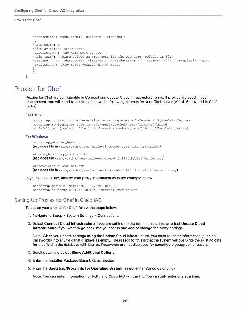
"expression": "node.normal[:customer][:greeting]" }, "http.port": { "display_name": "HTTP Port", "description": "The HTTP port to use.", "help_text": "Please select an HTTP port for the web page. Default is 80.", "options": "", "data_type": "integer", "validation": "", "value": "99", "required": "no", "expression": "node.force_default[:http][:port]" } }
}
Proxies for ChefProxies for Chef are configurable in Connect and update Cloud infrastructure forms. If proxies are used in your environment, you will need to ensure you have the following patches for your Chef server (v11.4-6 provided in Chef folder).
For Linuxbootstrap_context.rb (replaces file in <ruby-path-to-chef-gems>/lib/chef/knife/core)bootstrap.rb (replaces file in <ruby-path-to-chef-gems>/lib/chef/knife)chef-full.erb (replaces file in <ruby-path-to-chef-gems>/lib/chef/knife/bootstrap)
For Windowsbootstrap_windows_base.rb
(replaces file in <ruby-path>/gems/knife-windows-0.5.13/lib/chef/knife/)
windows_bootstrap_context.rb
(replaces file <ruby-path>/gems/knife-windows-0.5.13/lib/chef/knife/core)
windows-chef-client-msi.erb
(replaces file in <ruby-path>/gems/knife-windows-0.5.13/lib/chef/knife/bootstrap)
In your knife.rb file, include your proxy information as in the example below
bootstrap_proxy = ‘http://64.102.255.40:8080’bootstrap_no_proxy = ‘192.168.1.*, internal.chef.server’
Setting Up Proxies for Chef in Cisco IACTo set up your proxies for Chef, follow the steps below.
1. Navigate to Setup > System Settings > Connections.
2. Select Connect Cloud Infrastructure if you are setting up the initial connection, or select Update Cloud Infrastructure if you want to go back into your setup and add or change the proxy settings.
Note: When you update settings using the Update Cloud Infrastructure, you must re-enter information (such as passwords) into any field that displays as empty. The reason for this is that the system will overwrite the existing data for that field in the database with blanks. Passwords are not displayed for security / cryptographic reasons.
3. Scroll down and select Show Additional Options.
4. Enter the Installer Package Base URL as needed.
5. From the Bootstrap/Proxy info for Operating System, select either Windows or Linux.
Note: You can enter information for both, and Cisco IAC will track it. You can only enter one at a time.
26
Configuring Chef for Cisco IAC Integration
Setting Up Chef 12.0.x on Cisco PSC to Work with vCenter 6.x
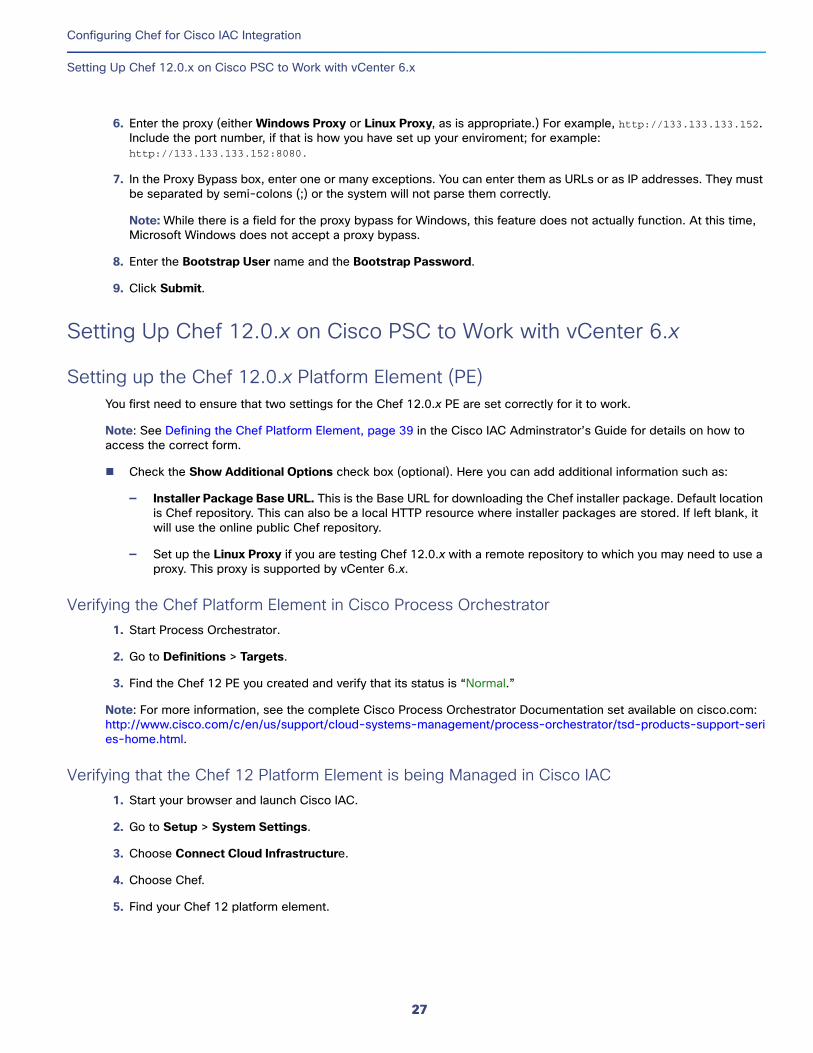
6. Enter the proxy (either Windows Proxy or Linux Proxy, as is appropriate.) For example, http://133.133.133.152. Include the port number, if that is how you have set up your enviroment; for example: http://133.133.133.152:8080.
7. In the Proxy Bypass box, enter one or many exceptions. You can enter them as URLs or as IP addresses. They must be separated by semi-colons (;) or the system will not parse them correctly.
Note: While there is a field for the proxy bypass for Windows, this feature does not actually function. At this time, Microsoft Windows does not accept a proxy bypass.
8. Enter the Bootstrap User name and the Bootstrap Password.
9. Click Submit.
Setting Up Chef 12.0.x on Cisco PSC to Work with vCenter 6.x
Setting up the Chef 12.0.x Platform Element (PE)You first need to ensure that two settings for the Chef 12.0.x PE are set correctly for it to work.
Note: See Defining the Chef Platform Element, page 39 in the Cisco IAC Adminstrator’s Guide for details on how to access the correct form.
Check the Show Additional Options check box (optional). Here you can add additional information such as:
— Installer Package Base URL. This is the Base URL for downloading the Chef installer package. Default location is Chef repository. This can also be a local HTTP resource where installer packages are stored. If left blank, it will use the online public Chef repository.
— Set up the Linux Proxy if you are testing Chef 12.0.x with a remote repository to which you may need to use a proxy. This proxy is supported by vCenter 6.x.
Verifying the Chef Platform Element in Cisco Process Orchestrator1. Start Process Orchestrator.
2. Go to Definitions > Targets.
3. Find the Chef 12 PE you created and verify that its status is “Normal.”
Note: For more information, see the complete Cisco Process Orchestrator Documentation set available on cisco.com: http://www.cisco.com/c/en/us/support/cloud-systems-management/process-orchestrator/tsd-products-support-series-home.html.
Verifying that the Chef 12 Platform Element is being Managed in Cisco IAC1. Start your browser and launch Cisco IAC.
2. Go to Setup > System Settings.
3. Choose Connect Cloud Infrastructure.
4. Choose Chef.
5. Find your Chef 12 platform element.
27
Configuring Chef for Cisco IAC Integration
Setting Up Chef 12.0.x on Cisco PSC to Work with vCenter 6.x
Discovering the New Chef 12 Role Note: For more detailed information on the forms and navigation used in resource discovery, see Managing Resources Using Discovery, page 19 of the Cisco Intelligent Automation for Cloud Administrator Guide.
1. Start Cisco IAC.
2. Select Setup > Manage Infrastructure.
3. Select Chef from the left platform elements column.
4. On the Chef page, click the Discover Chef Roles option.
5. Click Submit Order.
Verifying that the New Role was Successfully Discovered1. Select Setup > Manage Infrastructure again.
2. Select Chef from the platform elements in the left-hand column.
3. Review the list of role names and verify that the new role name is in the list and is shown as “Discovered.”
Registering Environment and RolesNote: For more detailed information on the forms and navigation used in roles, see User Roles and Capabilities, page 25. For information on resources, see Managing Services, page 13 as well as Managing Resources Using Discovery, page 19 of the Cisco Intelligent Automation for Cloud Administrator Guide.
You only need to register Roles and Environment. These elements should be displayed with a status of “Discovered.”
1. To register a Role, find your the correct Role that you want to register (it will currently be listed as “Discovered”).
2. Click the gear icon ⚙ next to that Role and then choose Register Role from the popup.
3. On the Chef Role Registration form, enter:
a. A friendly name
b. An application code; for example:
— iis for Windows
— web (apache) for Linux
c. Price
d. Tenant access
e. Operating System: Part of registering role is selecting which platform the role supports. Options are Both, Windows, and Linux. This is a required field.
4. Click Submit.
Note: Register an Environment in the same way.
Ordering a Compute PODNote: For more detailed information on the forms and navigation used in working with PODs, see Managing PODs, page 125 of the Cisco Intelligent Automation for Cloud Administrator Guide.
1. Select Setup > System Settings > PODs.
28
Configuring Chef for Cisco IAC Integration
Setting Up Chef 12.0.x on Cisco PSC to Work with vCenter 6.x
2. Choose Register a Compute POD.
3. Under the POD Details area, enter a Compute POD Name and an optional Description.
4. Select the location for Cisco Process Orchestrator from the Location drop down.
5. From the Cloud Infrastructure Type drop down, select one of the following twp options from the list:
— OpenStack Platform Element
— VMware vCenter Server
For OpenStack:a. From the Network POD Name drop down, select the Network POD instance that serves in this POD.
b. From the Open Stack Cloud Manager Instance drop down, select the Open Stack Cloud Manager that contains the hosts in this POD.
For VMware:a. From the Network POD Name drop down, select the Network POD instance that serves in this POD.
b. From the VMware vCenter Instance drop down, select the vCenter instance that controls hypervisor hosts in this POD.
c. From the VMware Datacenter drop down, select the vcenter dataoenter that contains the hypervisor hosts in this POD.
d. From the Cisco UCS Manager Instance drop down, select
e. From theCisco UCS Director Baremetal Agent drop down, select the U08 Manager instance that controls the servers in this POD.
f. From the Provisioning UCS VLAN drop down, select the appropriate provisioning vLAN.
g. From the Provisioning Hypervisor VLAN, , select the appropriate provisioning vLAN.
6. Click Submit Order.
7. Verify that the req has completed successfully in Process Orchestrator.
Registering a Service Resource ContainerNote: Instructions given below are specific to the task at hand. For more detailed information on the forms and navigation used in managing containers, see Managing Containers, page 131 of the Cisco Intelligent Automation for Cloud Administrator Guide.
1. On the Modify Service Resource Container form, enter the necessary information.
2. Click Submit Order.
Creating Tenants and OrganizationsNote: Instructions given below are specific to the task at hand. For more detailed information on the forms and navigation used in managing orgs and tenants, see Managing Tenants, page 91 and of the Cisco Intelligent Automation for Cloud Administrator Guide.Managing Organizations and Users, page 65.
Creating the Tenant1. On the Create Tenant form, complete all required fields.
29
Configuring Chef for Cisco IAC Integration
Setting Up Chef 12.0.x on Cisco PSC to Work with vCenter 6.x
2. Select YES for the following:
a. Create Virtual Data Center
b. Create Virtual Machine From Template
c. Application Configuration Management
3. Click Submit Order.
Creating the OrganizationYou then create an organization under that tenant.
1. On the Create Organizations form, complete all required fields.
2. Select YES for the following:
a. Virtual Machine From Template Ordering
b. Application Configuration Management
c. Virtual Data Center Ordering
3. Select your Service Resource Container.
4. Click Submit Order.
Creating a Network You need to create a network before you proceed with creating a VDC.
Note: For more detailed information on the forms and navigation used in creating networks, see Provisioning and Managing Networks, page 97 of the Cisco Intelligent Automation for Cloud Administrator Guide.
Creating and Ordering VDCs
Creating the Virtual Data CenterNote: For more detailed information on the forms and navigation used in creating and managing VDCs, see Managing Servers, Virtual Machines, and Virtual Data Centers, page 103 of the Cisco Intelligent Automation for Cloud Administrator Guide.
1. Go to my VDCs or Order Services and launch Create VDC order form.
2. Select your Tenant.
3. Select your Organization.
4. Click Submit Order.
Ordering VDCsOn the Order VDC Form, complete the following fields:
VDC Details:
— VDC Name
— Domain Name
30
Configuring Chef for Cisco IAC Integration
Setting Up Chef 12.0.x on Cisco PSC to Work with vCenter 6.x
— POD Name
— Cluster Name
— Datastore Name
— Snapshots Per VM Limit
— CPU Limit (MHz)
Resource Pool Details
— Resource Pool
— CPU Reservation (MHz)
— Memory Reservation (GB)
Note: Be sure to set the Chef12 network as the primary network.
31

Configuring Chef for Cisco IAC Integration
Setting Up Chef 12.0.x on Cisco PSC to Work with vCenter 6.x
32
Installing Cisco IAC Process Orchestrator Automation Packs
In this chapter, you will find instructions for installing the following automation packs:
Intelligent Automation for Compute.tap
Intelligent Automation for Cloud Starter.tap
Intelligent Automation for Cloud.tap
Intelligent Automation for Cloud Extension Samples.tap (optional but recommended)
Note: You first need to install Cisco Process Orchestrator 3.2. For full instructions, refer to the Process Orchestrator documentation, located here: http://www.cisco.com/c/en/us/support/cloud-systems-management/process-orchestrator/tsd-products-support-series-home.html
Note: Be sure to create a backup of both the Cisco Process Orchestrator database and the Cisco Prime Service Catalog database before you install Cisco IAC 4.3.
Important: If you are upgrading from Cisco IAC 4.1.1 or 4.2, see Upgrading From Cisco IAC 4.1.1 or 4.2, page 89 instead.
Launching the Setup Wizard1. Download the Cisco IAC 4.3 installer. The Cisco Process Orchestrator content files are part of the build file named
IAC 4.3.xxxx.
Note: To find the latest file, navigate to http://software.cisco.com. Find the downloads link and look for Cisco Intelligent Automation for Cloud as the software.
2. Un-zip IAC4.3.xxx.
3. Locate the Cisco IAC 4.3 setup.exe file and run it to start the Setup Wizard.
Note: The zip file unpacks into two high-level folders: Prime Service Catalog and Process Orchestrator. The setup.exe file is in the Process Orchestrator folder.
4. Click Next to proceed to the next step.
5. On the Information page, click Next again to continue.
6. On the Confirm Installation page, click Next to continue.
7. On the Installation Complete page, check the Launch automation pack import wizard now check box.
8. Click Close to launch the Automation Pack Import Wizard. The Import Wizard will first configure itself.
33
Cisco Systems, Inc. www.cisco.com
Installing Cisco IAC Process Orchestrator Automation Packs
Installing the Core and Common Automation Packs
Installing the Core and Common Automation PacksThe Choose Automation Packs dialog box displays. This dialog box shows you a list all available automation packs and other services required for Cisco IAC 4.3. These include the TAPs you just installed, as well as Core and Common Activities. These are presented in a checklist format, and are pre-checked for your convenience.
Note: You must install both the Core and the Common Activities packs. The Cisco IAC packs are dependent on functionality within these packs in order to function properly. In fact, without the Core and Common Activities TAPs, the Cisco IAC TAPs will not import.
1. Click OK to continue with chosen options.
2. On the Welcome to the Automation Pack Import Wizard panel, click Next.
3. You do not need to enter information on the General Information panel because we are importing the Core and Common Activities. Before you click Next, make sure the Core and Common Activities Packs are selected.
4. Click Next.
5. Enter Keystore Password (required for keystore file containing email digital signatures).
6. On the Email Configuration panel, provide the default SMTP server and sender’s e-mail address to be used for e-mail activities, click Next.
7. The Automation Summary Configuration panel indicates where the automation summary reports that are generated by activities are to be saved and how long the reports are to be retained. The specified file paths will be used to access and view the automation summary reports.
On the Automation Summary Configuration panel, specify the following information.
a. Accept the default directory, or enter a different file path for the automation summary directory in the Share Path field. You can also browse to navigate to the file path for the automation summary.
b. Enter credentials as needed. (These are not required.)
c. In the Virtual directory mapping area you create the share folder that corresponds to a virtual directory in IIS. Note that you may only create the virtual directory in the local IIS.
— Check the Enable virtual directory mapping check box.
— Click Create.
The Create Virtual Directory dialog box displays, pre-populated with default settings.
— Click OK to accept.
Note: Back in the Virtual directory path field, you can edit the string (http://host:(port)/ sharefolder) if needed.
8. Scroll down and you will see the Automation summary reports grooming settings area. The default deletion period is thirty days, but you can set this to whatever you want, from 1 to 9999. Or, choose the Delete automation summary reports older than check box to remove the check and all reports will be saved indefinitely.
9. When you are done working with the Automation Summary Configuration panel, click Next.
10. On the Data Extraction panel, un-check all of the data options below and then click Next.
— Business Objects Reports
— Microsoft SCOM Management Packs
— SQL Server Reporting Services Reports
34
Installing Cisco IAC Process Orchestrator Automation Packs
Installing the Cisco IAC Automation Packs
Note: Take a note of the folder name where the extracted data will be placed and uncheck the SQL Server Reporting Services Reports if you are not using the MS SQL Reporting solution.
The Review Prerequisites panel displays the prerequisites for the automation pack being imported, and will indicate either pass or fail for each prerequisite.
After the prerequisite check has completed (and passed), the Importing Objects panel displays.
After the objects have been imported, the General Information panel displays.
Installing the Cisco IAC Automation PacksThe four Cisco Automation packs are installed next. These include, in sequence:
Intelligent Automation for Compute.tap
Intelligent Automation for Cloud Starter.tap
Intelligent Automation for Cloud.tap
Intelligent Automation for Cloud Extension Samples.tap (optional but recommended)
The install process for each Automation Pack is explained next.
Installing the Intelligent Automation for Compute Pack1. On the General Information panel, review the information there. Note that the Name field now displays “Intelligent
Automation for Compute.” This is the first Cisco IAC automation pack that you will be installing.
2. Click Next.
3. On the Default Incidents Assignee Setup panel, specify the default user which to assign cloud-related incidents. This is a CPTA (Cloud Provider Technical Administrator) account, or would be within an Active Directory group that was created for all of CPTAs in this Cloud.
4. Click Next.
5. On the Cisco Process Orchestrator Web Service panel, specify the following data. Check the Enable non-secure Web Service (HTTP) check box in the Web Service Settings area. This setting unencrypts the HTTP endpoints.
Note: If or when presented with a security warning message, click OK.
6. Enter or verify the HTTP Port for the Process Orchestrator web target.
7. Choose the appropriate authentication method for the web service:
— Basic—Standard method that provides a username and plain-text password to the authentication mechanism.
— Digest—Method that provides a username and a hashed password to the authentication mechanism.
— NTLM—Default. Authentication protocol that is used on networks that include systems running the Windows operating system and on stand-alone systems.
Note: The NTLM setting supports both NTLM and NTLMv2. In IIS, NTLM is not enabled by default; you must enable NTLM in IIS if you choose this authentication mechanism. The agents in Prime Service Catalog must also be set to use the same authentication that you specify here.
8. When you are done, click Next to continue.
35
Installing Cisco IAC Process Orchestrator Automation Packs
Installing the Cisco IAC Automation Packs
9. Enter your credentials:
a. On the Default Web Service Credentials panel, specify the credentials for connecting to the Process Orchestrator web service target.
b. When done, click Next to continue.
10. Enter a password for VMware keystore access.
The VMware keystore password protects the Java keystore file used to keep SSL certificates for all configured VMware targets.
— For new installations, this password can be set to any valid six-character keytool password.
Note: If the VMware vSphere PowerCLI has not already been installed in the Process Orchestrator server, the wizard displays an information panel informing you of the situation. You can select Choose this check box to continue with the import to proceed. However, if you are using VMware vCenter and you have not yet installed VMware vSphere PowerCLI, the contents of the automation pack may not work correctly, if at all, until PowerCLI has been installed.
11. Click Next.
12. You will see a process screen display whereby the prerequisites are verified, and then objects are imported.
13. You will then be returned to the General Information panel to install the next Automation Pack.
Installing the Intelligent Automation for Cloud Starter Pack1. On the General Information panel, review the information about the automation pack. Note that the Name field now
displays “Intelligent Automation for Cloud Starter.”
2. Click Next.
3. On Configure Process Database Grooming panel, specify the number of days to keep process instances in the database. After the specified number of days, the process instances will be deleted from the database. The default value should be satisfactory.
4. Click Next to continue.
5. The Data Extraction panel is used to specify the destination where the data is extracted on the Process Orchestrator server. You can simply accept the default location, or browse to specify a different location to extract the files.
6. The Review Prerequisites panel displays briefly and you will see the prerequisites being processed.
7. Next, the Importing Objects panel displays its various progress bars as the data is imported and extracted. This may take some time to complete.
8. When the import is complete, you are automatically returned to the General Information panel.
9. Click Next.
Installing the Intelligent Automation for Cloud Extension Samples (Optional)1. On the General Information panel, review the information about the automation pack. Note that the Name field now
displays “Intelligent Automation for Cloud Extension Samples.”
2. Click Next.
a. The Review Prerequisites panel displays briefly and you will see the prerequisites being processed.
b. Next, the Importing Objects panel displays progress bars as the data is imported and extracted. This may take some time to complete.
36
Installing Cisco IAC Process Orchestrator Automation Packs
Installing the Cisco IAC Automation Packs
When the import is complete, you are automatically returned to the General Information panel.
3. On the General Information panel, click Next to import the Common Activities Automation Pack.
a. The Review Prerequisites panel displays briefly and you will see the prerequisites being processed.
b. Next, the Importing Objects panel displays progress bars as the data is imported and extracted. This may take some time to complete.
c. When the import of the common activities is complete, you are automatically returned to the General Information panel once again.
4. On the General Information panel.
5. Click Next.
6. Enter the destination for the extracted data, and choose the data to extract (or un-choose, really, as all of the data has been preselected for you).
7. Click Next to continue.
8. Once again, the Review Prerequisites panel displays briefly and you will see the prerequisites being processed.
a. As before, the Importing Objects panel displays its various progress bars as the data is imported and extracted. This may take some time to complete.
b. When the import process is complete, the Automation Pack Import Wizard panel displays.
Installing the Intelligent Automation for Cloud Pack1. On the General Information panel, review the information about the automation pack. Note that the Name field now
displays “Intelligent Automation for Cloud.”
2. Click Next.
3. On Configure Process Database Grooming panel, specify the number of days to keep process instances in the database. After the specified number of days, the process instances will be deleted from the database. The default value should be satisfactory. Click Next to continue.
4. The Data Extraction panel is used to specify the destination where the data is extracted on the Process Orchestrator server. You can simply accept the default location, or browse to specify a different location to extract the files, then click Next.
5. The Review Prerequisites panel displays briefly and you will see the prerequisites being processed.
6. Next, the Importing Objects panel displays its various progress bars as the data is imported and extracted. This may take some time to complete.
7. When the import is complete, you are automatically returned to the General Information panel.
Completing the ProcessAfter the objects have been imported, the Final Automation Pack Import Wizard Screen displays.
Review the information below the “Completing the Automation Pack Import Wizard” heading to verify that all is correct.
— For Cisco IAC, leave the Refresh Web Server check box checked.
— When you are done reviewing the information here, click Close to close the wizard.
37

Installing Cisco IAC Process Orchestrator Automation Packs
Installing the Cisco IAC Automation Packs
You have now successfully installed all supporting software for Cisco Process Orchestrator.
38
Installing Cisco IAC Components for a Fresh Installation
Be sure to create a backup of both the Cisco Process Orchestrator database and the Cisco Prime Service Catalog database before you install Cisco IAC 4.3.
Important: If you are upgrading from Cisco IAC 4.1.1 or 4.2, see Upgrading From Cisco IAC 4.1.1 or 4.2, page 89 instead.
Installing Prime Service Catalog ContentThe process of installing Prime Service Catalog using the installation packages consists of three steps:
Installing the REX Adapter
Note: For instructions on installing the REX Adapter, see Installing (or Reinstalling) the REX Adapter, page 89 (in the chapter called, Upgrading From Cisco IAC 4.1.1 or 4.2).
Importing and Deploying Portal Packages
Importing and Deploying PSC Catalogs
These steps are outlined in detail below.
Note: Follow these steps with the post-installation steps, as described in Post-Installation Tasks, page 43.
Importing and Deploying Portal PackagesCisco IAC ships with packaged image files and portal pages to provide an easy-to-use portal for ordering services.
Note: The zip file unpacks into two high-level folders: Prime Service Catalog and Process Orchestrator. The Service Catalog files are in the Prime Services Catalog folder.
Importing IAC Packages on PSC Windows EnvironmentsImporting the IAC packages on Prime Service Catalog Windows environments with Microsoft Internet Information Services (IIS) for Windows® Server requires the following IIS settings changes. Internet Information Services 7.5 has a default limit of 30 MB for all upload file. You can change this limit by performing the following steps:
1. Open Server Manager window.
2. In the first (left-most) panel, expand Server Manager - Roles - Web Server (IIS) - Internet Information Services (IIS) Manager.
3. In the second (middle) panel, expand hostname - Sites - Default Web Site.
4. Click Default Web Site.
5. In the third (middle) panel, click Request Filtering.
39
Cisco Systems, Inc. www.cisco.com
Installing Cisco IAC Components for a Fresh Installation
Installing Prime Service Catalog Content
6. In the fourth (right-most) panel, click the link Edit Feature Settings…
7. On the Edit Request Filtering Settings popup dialog, change the value for Maximum allowed content length (Bytes) from 30,000,000 to a larger number, such as 60,000,000.
8. Click OK.
9. Restart World Wide Web Publishing Service.
Importing IAC Packages Using the Prime Service Catalog Appliance Update timeout at httpd.conf :
— /etc/httpd/conf/httpd.conf
— set timeout to 1600
An alternative is to deploy the packages going direct to WildFly:
— http://applianceIP:8080/RequestCenter
Copying the Cisco IAC Portlets Package and Extracting Files1. . Navigate to the folder whereIAC-ServiceCatalog-4.3_xxxx.xxx was extracted. You will see names along the lines
of “CS_Services_4-3.xml.”
Note: The file is in a compressed (ZIP) file and will need to be extracted. There is also a ZIP file with the Prime Service Catalog files in it.
2. Extract IACPortlets-4.3_xxxx.xxx from the compressed (ZIP) file to a temporary location. It will create an IACPortlets-4.3_xxxx.xxx folder.
3. Stop the WildFly application server by stopping:
a. Cisco Prime Service Link, and then
b. Cisco Prime Service Catalog
Note: For instructions, see “How to Stop/Start the WildFly Server” in the Cisco Prime Service Catalog 11.1 Installation Guide. The latest version can be found here: http://www.cisco.com/c/en/us/support/cloud-systems-management/prime-service-catalog-10-0/model.html#InstallandUpgradeGuides
4. In the IACPortlets-4.3_xxxx.xxx folder, locate RequestCenter_war.zip.
5. Extract RequestCenter_war.zip to the following directory (for Windows):
(WildFly_DIR)\ServiceCatalogServer\deployments\RequestCenter.war
Note: Overwrite any existing files, if prompted.
6. Restart the WildFly application server:
a. Restart Cisco Prime Service Link.
b. Restart Cisco Prime Service Catalog.
Note: The above order is a change from prior versions of Cisco IAC; in fact, it is the reverse of how it was done previously.
40
Installing Cisco IAC Components for a Fresh Installation
Installing Prime Service Catalog Content
Importing and Deploying Portal PagesDeploy the Cisco IAC portal page content by importing it from the PortalPages.xml portal page file, located in the IACPortlets folder.
1. Choose Portal Designer from the module drop-down list to open Portal Designer.
2. In Portal Designer, click the Portal Pages tab.
3. In the left navigation pane, click Actions and choose Import from the drop-down list.
4. On the Import Portal Pages dialog box, click the Overwrite radio button in the Conflict Resolution field.
5. In the Import from File field, click Choose File to navigate to the IACPortlets folder that you extracted earlier.
a. On the Choose File to Upload dialog box, choose the PortalPages.xml file and click Open.
b. On the Import Portal Pages dialog box, click Import.
6. Refresh your browser to view the imported portal.
Installing and Configuring the REX AdapterNote: See Installing (or Reinstalling) the REX Adapter, page 89 for details.
Importing and Deploying PSC CatalogsComplete the following procedure to import and deploy catalogs in Prime Service Catalog. Note that you must be logged into Prime Service Catalog with administrator privileges to perform the procedures.
Installing the Catalogs1. Open a browser and launch Cisco Prime Service Catalog.
2. Log into the Prime Service Catalog ServiceCatalog web portal as the site administrator
3. Choose Catalog Deployer from the module drop-down list.
4. In the Deployment Packages pane, and choose Action > Import from the drop-down list.
5. On the Import Package from File dialog box, click Browse to navigate to the folder where you saved the Prime Service Catalog files.
6. Choose the SC_Common_4-3_NEW_INSTALL_ONLY.xml file and click Import.
Note: For new installations, DO NOT import or deploy SC_Common_4-3.xml.
7. When the message Package Imported Successfully displays, click OK.
The Deployment Packages window refreshes to display the imported package in the Received for Deployment view.
8. Repeat Steps 4 - 7 again to import SC_Services_4-3.xml.
9. Repeat Steps 4 - 7 again to import SC_Common_4-3_Overwrite.xml.
41
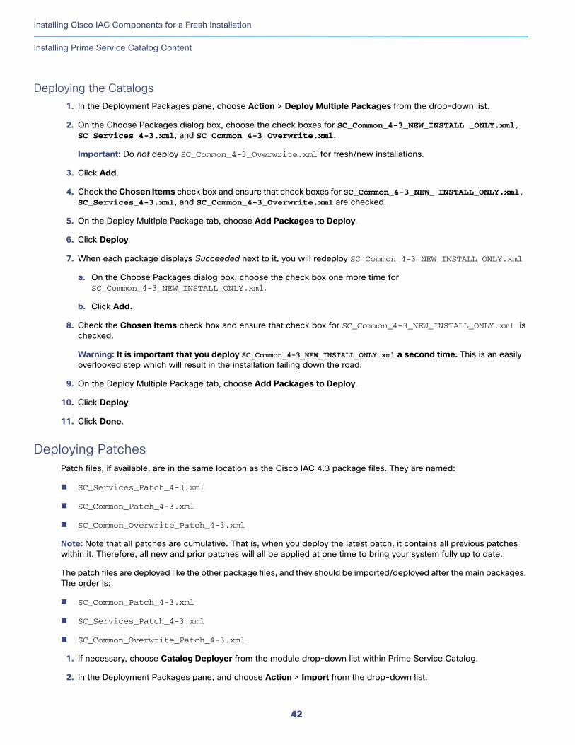
Installing Cisco IAC Components for a Fresh Installation
Installing Prime Service Catalog Content
Deploying the Catalogs1. In the Deployment Packages pane, choose Action > Deploy Multiple Packages from the drop-down list.
2. On the Choose Packages dialog box, choose the check boxes for SC_Common_4-3_NEW_INSTALL _ONLY.xml, SC_Services_4-3.xml, and SC_Common_4-3_Overwrite.xml.
Important: Do not deploy SC_Common_4-3_Overwrite.xml for fresh/new installations.
3. Click Add.
4. Check the Chosen Items check box and ensure that check boxes for SC_Common_4-3_NEW_ INSTALL_ONLY.xml, SC_Services_4-3.xml, and SC_Common_4-3_Overwrite.xml are checked.
5. On the Deploy Multiple Package tab, choose Add Packages to Deploy.
6. Click Deploy.
7. When each package displays Succeeded next to it, you will redeploy SC_Common_4-3_NEW_INSTALL_ONLY.xml
a. On the Choose Packages dialog box, choose the check box one more time for SC_Common_4-3_NEW_INSTALL_ONLY.xml.
b. Click Add.
8. Check the Chosen Items check box and ensure that check box for SC_Common_4-3_NEW_INSTALL_ONLY.xml is checked.
Warning: It is important that you deploy SC_Common_4-3_NEW_INSTALL_ONLY.xml a second time. This is an easily overlooked step which will result in the installation failing down the road.
9. On the Deploy Multiple Package tab, choose Add Packages to Deploy.
10. Click Deploy.
11. Click Done.
Deploying PatchesPatch files, if available, are in the same location as the Cisco IAC 4.3 package files. They are named:
SC_Services_Patch_4-3.xml
SC_Common_Patch_4-3.xml
SC_Common_Overwrite_Patch_4-3.xml
Note: Note that all patches are cumulative. That is, when you deploy the latest patch, it contains all previous patches within it. Therefore, all new and prior patches will all be applied at one time to bring your system fully up to date.
The patch files are deployed like the other package files, and they should be imported/deployed after the main packages. The order is:
SC_Common_Patch_4-3.xml
SC_Services_Patch_4-3.xml
SC_Common_Overwrite_Patch_4-3.xml
1. If necessary, choose Catalog Deployer from the module drop-down list within Prime Service Catalog.
2. In the Deployment Packages pane, and choose Action > Import from the drop-down list.
42
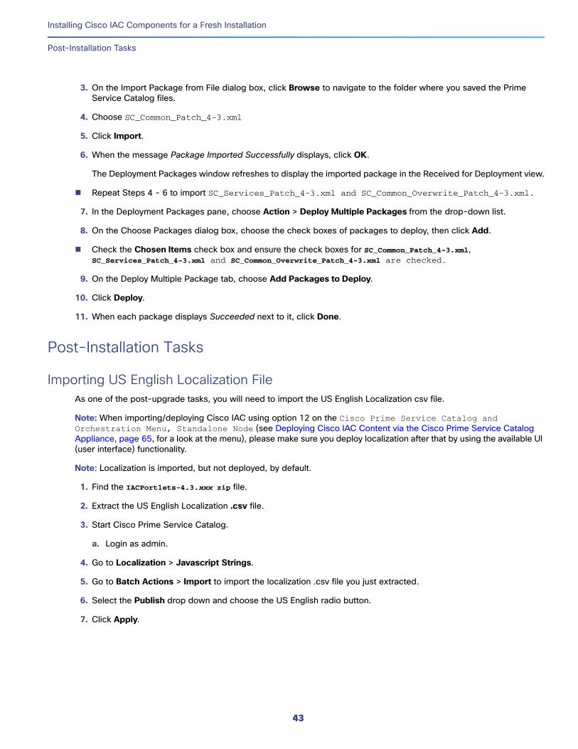
Installing Cisco IAC Components for a Fresh Installation
Post-Installation Tasks
3. On the Import Package from File dialog box, click Browse to navigate to the folder where you saved the Prime Service Catalog files.
4. Choose SC_Common_Patch_4-3.xml
5. Click Import.
6. When the message Package Imported Successfully displays, click OK.
The Deployment Packages window refreshes to display the imported package in the Received for Deployment view.
Repeat Steps 4 - 6 to import SC_Services_Patch_4-3.xml and SC_Common_Overwrite_Patch_4-3.xml.
7. In the Deployment Packages pane, choose Action > Deploy Multiple Packages from the drop-down list.
8. On the Choose Packages dialog box, choose the check boxes of packages to deploy, then click Add.
Check the Chosen Items check box and ensure the check boxes for SC_Common_Patch_4-3.xml, SC_Services_Patch_4-3.xml and SC_Common_Overwrite_Patch_4-3.xml are checked.
9. On the Deploy Multiple Package tab, choose Add Packages to Deploy.
10. Click Deploy.
11. When each package displays Succeeded next to it, click Done.
Post-Installation Tasks
Importing US English Localization FileAs one of the post-upgrade tasks, you will need to import the US English Localization csv file.
Note: When importing/deploying Cisco IAC using option 12 on the Cisco Prime Service Catalog and Orchestration Menu, Standalone Node (see Deploying Cisco IAC Content via the Cisco Prime Service Catalog Appliance, page 65, for a look at the menu), please make sure you deploy localization after that by using the available UI (user interface) functionality.
Note: Localization is imported, but not deployed, by default.
1. Find the IACPortlets-4.3.xxx zip file.
2. Extract the US English Localization .csv file.
3. Start Cisco Prime Service Catalog.
a. Login as admin.
4. Go to Localization > Javascript Strings.
5. Go to Batch Actions > Import to import the localization .csv file you just extracted.
6. Select the Publish drop down and choose the US English radio button.
7. Click Apply.
43
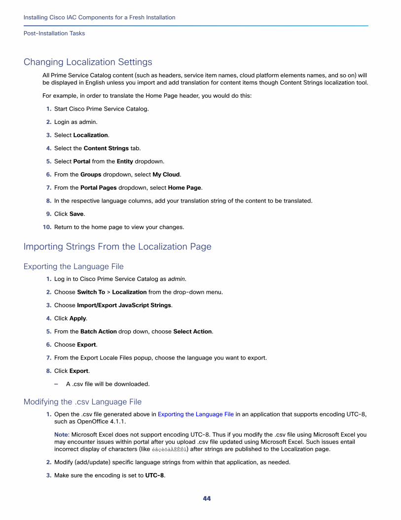
Installing Cisco IAC Components for a Fresh Installation
Post-Installation Tasks
Changing Localization SettingsAll Prime Service Catalog content (such as headers, service item names, cloud platform elements names, and so on) will be displayed in English unless you import and add translation for content items though Content Strings localization tool.
For example, in order to translate the Home Page header, you would do this:
1. Start Cisco Prime Service Catalog.
2. Login as admin.
3. Select Localization.
4. Select the Content Strings tab.
5. Select Portal from the Entity dropdown.
6. From the Groups dropdown, select My Cloud.
7. From the Portal Pages dropdown, select Home Page.
8. In the respective language columns, add your translation string of the content to be translated.
9. Click Save.
10. Return to the home page to view your changes.
Importing Strings From the Localization Page
Exporting the Language File1. Log in to Cisco Prime Service Catalog as admin.
2. Choose Switch To > Localization from the drop-down menu.
3. Choose Import/Export JavaScript Strings.
4. Click Apply.
5. From the Batch Action drop down, choose Select Action.
6. Choose Export.
7. From the Export Locale Files popup, choose the language you want to export.
8. Click Export.
— A .csv file will be downloaded.
Modifying the .csv Language File1. Open the .csv file generated above in Exporting the Language File in an application that supports encoding UTC-8,
such as OpenOffice 4.1.1.
Note: Microsoft Excel does not support encoding UTC-8. Thus if you modify the .csv file using Microsoft Excel you may encounter issues within portal after you upload .csv file updated using Microsoft Excel. Such issues entail incorrect display of characters (like éâçèöàÀËÊÉû) after strings are published to the Localization page.
2. Modify (add/update) specific language strings from within that application, as needed.
3. Make sure the encoding is set to UTC-8.
44
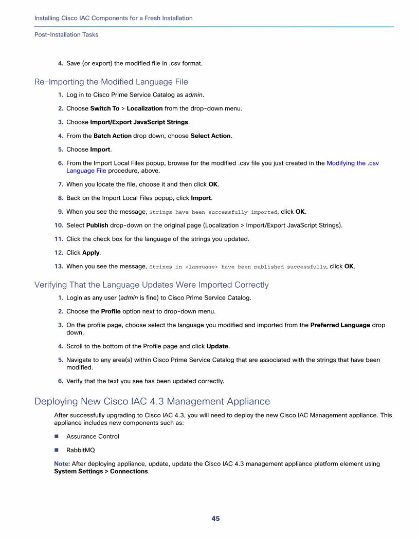
Installing Cisco IAC Components for a Fresh Installation
Post-Installation Tasks
4. Save (or export) the modified file in .csv format.
Re-Importing the Modified Language File1. Log in to Cisco Prime Service Catalog as admin.
2. Choose Switch To > Localization from the drop-down menu.
3. Choose Import/Export JavaScript Strings.
4. From the Batch Action drop down, choose Select Action.
5. Choose Import.
6. From the Import Local Files popup, browse for the modified .csv file you just created in the Modifying the .csv Language File procedure, above.
7. When you locate the file, choose it and then click OK.
8. Back on the Import Local Files popup, click Import.
9. When you see the message, Strings have been successfully imported, click OK.
10. Select Publish drop-down on the original page (Localization > Import/Export JavaScript Strings).
11. Click the check box for the language of the strings you updated.
12. Click Apply.
13. When you see the message, Strings in <language> have been published successfully, click OK.
Verifying That the Language Updates Were Imported Correctly1. Login as any user (admin is fine) to Cisco Prime Service Catalog.
2. Choose the Profile option next to drop-down menu.
3. On the profile page, choose select the language you modified and imported from the Preferred Language drop down.
4. Scroll to the bottom of the Profile page and click Update.
5. Navigate to any area(s) within Cisco Prime Service Catalog that are associated with the strings that have been modified.
6. Verify that the text you see has been updated correctly.
Deploying New Cisco IAC 4.3 Management ApplianceAfter successfully upgrading to Cisco IAC 4.3, you will need to deploy the new Cisco IAC Management appliance. This appliance includes new components such as:
Assurance Control
RabbitMQ
Note: After deploying appliance, update, update the Cisco IAC 4.3 management appliance platform element using System Settings > Connections.
45

Installing Cisco IAC Components for a Fresh Installation
Post-Installation Tasks
Application Configuration Management Support To use an existing tenant created in an earlier version of Cisco IAC, your CPBA or CPTA will need to create the “ACMTemplate Rate” table manually.
Note: For instructions on creating the “ACMTemplate Rate” table manually, see the Cisco Intelligent Automation for Cloud Knowledge Base here:
http://www.cisco.com/c/en/us/support/cloud-systems-management/intelligent-automation-cloud/tsd-products-support-series-home.html
46
Optional TasksSetting Up Active Directory Integration (If Applicable)
This section provides examples of setting up optional directory integration in Microsoft Active Directory. Because there are many scenarios for directory integration configuration based on the directory product and settings, it is likely that your environment will vary from what is presented here. However, the required sequence of configuring directory integration would be the same.
Cisco Prime Service Catalog can integrate with directory servers to synchronize user information. This synchronization can be initiated whenever a user logs on or is chosen or during Person Lookup in Prime Service Catalog. Prior to configuring integration in Prime Service Catalog, you must have a directory server installed and populated with corporate data.
Note: For instructions on configuring directory integration if your setup varies, see the Cisco Prime Service Catalog 10.x Integration Guide. The latest version can be found here: http://www.cisco.com/c/en/us/support/cloud-systems-management/prime-service-catalog-10-0/model.html#InstallandUpgradeGuides
PrerequisitesBefore configuring directory integration for use with Cisco IAC, you must complete the following tasks:
Set up organizational unit structure on the LDAP server. If you do not have privileges to perform this task on the LDAP server, seek help from your LDAP server administrator.
Create the following user accounts in the Users folder on the LDAP server:
— nsAPI user
— A user account (any username) with “Read MemberOf” permissions that will be used for performing authentication, directory searches, and user imports into the Prime Service Catalog.
Note: Cisco IAC 4.3 supports multiple memberships to multiple organizations. However, through Directory Integration these can only be mapped to a single organization. After the user has been imported, a CPTA can add the user to additional organizations and assign a Home OU (default organization).
Configuring an LDAP ServerThe first step is to add a data source and test the connection in Cisco Prime Service Catalog. The instructions in this section are how one would connect to the LDAP server in the example scenario.
1. Choose Service Portal from the module drop-down list, then click the System Settings from the Setup tab.
2. On the System Setup portal, click the Connections tab to open the portlet, then click Manage Directory Server Connection.
3. Click Add to display the Datasources Configuration pane.
4. In the Add or Edit a Datasource pane, enter the following:
47
Cisco Systems, Inc. www.cisco.com
Optional Tasks
Configuring Authentication
a. Enter a name for the datasource. Do not use spaces or special characters.
b. Enter a description of the datasource. (Optional.)
5. Expand Choose protocol and server product, then choose the following:
a. The protocol is always LDAP.
b. Choose MS Active Directory. (Other server options are Sun One or IBM Tivoli Directory Server.)
6. Expand Connection Information, then specify the following required datasource information in the definition area. This information includes lookup user that you set up as a prerequisite.
a. Choose Simple (text username and password) from the Authentication Method drop-down list.
b. Choose Non SSL from the Mechanism drop-down list.
c. Enter the bind-distinguished name (BindDN) value for the lookup user. The BindDN looks like the following example:
CN=Mehalic Michael,OU=Users,OU=Austin,OU=Texas,OU=USA, DC=notexist,DC=local
Note: PSC now supports the use of LAN Manager (down-level logon) formats now. You can still use the BindDN as you have it now but you can also use the format of domainname\username.
d. To query the BindDN value, open a command prompt on the Windows server and execute the following command:
e. dsquery user -name “[name]*”
f. Enter the fully qualified hostname or IP address of the LDAP directory server. For example: dc.notexist.local
g. Enter the parent folder under which all users will gain access.
h. For example, if the User BaseDN is OU=Austin,OU=Texas,OU=USA,DC=notexist,DC=local, then all users in the Austin organization will have access.
i. Enter the port number for the LDAP according to either of the following conditions:
— For a non-SSL connection, the default port number for LDAP is 389.
— For an SSL connection, the default port number for LDAP is 636.
j. You can verify the port number for your LDAP server using either by running the command netstat -an on the domain controller, or by using the SysInternals tool TCPView.exe.
k. Enter the password for the user specified as the BindDN.
7. Click Update.
8. Check the check box next to the newly added datasource and click Test Connection. The Test Status column displays OK if the connection is successful.
Configuring AuthenticationConfiguring authentication requires completing two tasks: configuring mappings and configuring events. The instructions in this section are how one would complete each task in the example scenario.
48
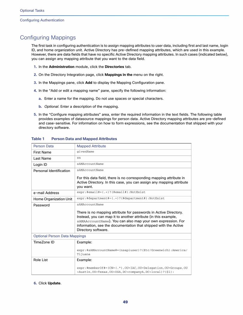
Optional Tasks
Configuring Authentication
Configuring MappingsThe first task in configuring authentication is to assign mapping attributes to user data, including first and last name, login ID, and home organization unit. Active Directory has pre-defined mapping attributes, which are used in this example. However, there are data fields that have no specific Active Directory mapping attributes. In such cases (indicated below), you can assign any mapping attribute that you want to the data field.
1. In the Administration module, click the Directories tab.
2. On the Directory Integration page, click Mappings in the menu on the right.
3. In the Mappings pane, click Add to display the Mapping Configuration pane.
4. In the “Add or edit a mapping name” pane, specify the following information:
a. Enter a name for the mapping. Do not use spaces or special characters.
b. Optional. Enter a description of the mapping.
5. In the “Configure mapping attributes” area, enter the required information in the text fields. The following table provides examples of datasource mappings for person data. Active Directory mapping attributes are pre-defined and case-sensitive. For information on how to form expressions, see the documentation that shipped with your directory software.
.
6. Click Update.
Table 1 Person Data and Mapped Attributes
Person Data Mapped Attribute
First Name givenName
Last Name sn
Login ID sAMAccountName
Personal Identification sAMAccountName
For this data field, there is no corresponding mapping attribute in Active Directory. In this case, you can assign any mapping attribute you want.
e-mail Address expr:#email#=(.+)?(#email#):NotExist
Home Organization Unit expr:#department#=(.+)?(#department#):NotExist
Password sAMAccountName
There is no mapping attribute for passwords in Active Directory. Instead, you can map it to another attribute (in this example, sAMAAccountName). You can also map your own expression. For information, see the documentation that shipped with the Active Directory software.
Optional Person Data Mappings
TimeZone ID Example:
expr:#sAMAccountName#=(nsapiuser)?(Etc/Greenwich):America/Tijuana
Role List Example:
expr:#memberOf#=(CN=(.*),OU=IAC,OU=Delegation,OU=Groups,OU=Austin,OU=Texas,OU=USA,DC=companyA,DC=local)?($1):
49
Optional Tasks
Configure Events
7. Test the mappings using the Data Test Mapping feature.
Note: For instructions on enabling then using the Data Test Mapping feature, see “Testing Mappings” in Chapter 1, “Directory Integration and API,” in the Cisco Prime Service Catalog 10.0 Integration Guide. The latest version of the technical reference guides can be found here: http://www.cisco.com/c/en/us/support/cloud-systems-management/prime-service-catalog/products-technical-reference-list.html
Configure Events1. Click Events in the menu on the right.
2. In the Events pane, click Edit next to the Login event to display the Event Configuration pane.
3. Choose Enabled from the Event Status drop-down list.
4. In the Event Configuration pane, click Add step, then specify the following:
a. Choose External Authentication.
b. Click Options, then enter the EUABindDN using the following convention:
<netbios domain>\#LoginId#
Note: You must provide the EUABindDN value, which is critical for login events. This value is case-sensitive. This attribute is a pre-defined Active Directory value. The attribute is different for other directories.
5. Click Update to add the information as the first step in the event.
6. Click Add step.
7. In the Step 2 row, choose Import Person from the Operation drop-down list.
8. From the Mapping drop-down list, choose the mapping name you specified when you defined mappings in the previous process.
9. From the Datasource drop-down list, choose the datasource name that you specified in Step 4, above.
a. Click Options, then specify the following information in the Event Step area:
b. Ensure that the Refresh Person Profile check box is checked.
c. Leave the Refresh Period (Hours) field blank. If a value populates the field, delete the value.
d. Do not create Group/OU:
— Organizational Unit—Check the check box. Checking this option prevents a user from logging in to the Prime Service Catalog Server unless the user’s home organization has been onboarded.
— Group—Uncheck the check box.
10. Click Update to add the information as Step 2 then click Update again.
11. In the Events pane, click Edit next to the Person Lookup for Service Form event to display the Event Configuration pane.
12. Choose Enabled from the Event Status drop-down list.
13. In the Event Configuration pane, click Add step, then specify the following information in the Options for Event Step1 area:
a. Choose Import Person as the Operation.
50
Optional Tasks
Creating a Security Group for Each User Role on the LDAP Server
b. Click Options.
— Enter 24 in the Refresh Period (Hours) field.
— Leave all check boxes unchecked.
14. Click Update to add the same information as did in Step 1, then click Update again.
Creating a Security Group for Each User Role on the LDAP ServerIn your directory, create one security group for each user role. The name of each group must exactly match the name of the user role:
Cloud Provider Technical Administrator
Cloud Provider Business Administrator
Tenant Technical Administrator
Tenant Business Administrator
Organization Technical Administrator
Virtual and Physical Server Owner
Virtual Server Owner
Solutions Team
Form Extender
For instructions on creating security groups on your directory server, see the documentation that came with your directory server software.
Note: Cisco Intelligent Automation for Cloud supports an individual’s membership to just a single organizational unit or membership, not multiple organizations.
Adding the nsAPI User to the Cloud Administration GroupThe nsAPI user account that you created on the LDAP server is used to connect Cisco Prime Service Catalog to Cisco Process Orchestrator. For the nsAPI user account to function properly, you must add it to the Cloud Provider Technical Administrator user group that you created in the directory. For instructions on adding a user to a user role group on your directory server, see the documentation that came with your directory server software.
Configuring User Role MappingsTo map user roles, you specify the location in the directory that contains the six security groups you created for each role.
1. In Service Catalog, choose Administration from the module drop-down list, then click Directories.
2. On the Directory Integration page, click Mappings in the menu on the right.
3. In the Mappings pane, click Edit beside the mapping name you created when you configured mappings (see Configuring Mappings, page 49).
4. Expand Optional Person Data Mappings at the bottom of the page.
51
Optional Tasks
Enabling Directory Integration
5. In the Role List field at the bottom of the optional mappings list, enter mapping attributes for role list that assigns the user to one of the six Cisco Prime Service Catalog user groups that you created in the directory. using the convention used for the example scenario (variables for the example appear in boldface):
expr:#memberOf#=(CN=(.*),OU=Groups,OU=Austin,OU=Texas,OU=USA,DC=notexist,DC=local)?($1):
6. Test the mappings using the Data Test Mapping feature.
Note: For instructions on enabling and using the Data Test Mapping feature, see “Testing Mappings” in “Directory Integration and API,” in the Cisco Prime Service Catalog 10.1 Integration Guide. The latest version of the technical reference guides can be found here: http://www.cisco.com/c/en/us/support/cloud-systems-management/prime-service-catalog/products-technical-reference-list.html
Enabling Directory IntegrationBefore you enable directory integration, be sure you have all user groups configured for use with Cisco IAC. If you do not have all user groups configured before you enable directory integration, you will not be able to log back in to Cisco Prime Service Catalog.
1. Choose Administration from the module drop-down list, then click Personalize Your Site.
2. On the Customizations page, scroll down to the Common Settings area and turn the Enable Directory Integration setting On.
3. Click the Update button at the bottom of the page.
Setting Global Variable to store OpenStack KeypairsKeypairs are required when ordering an OpenStack and Amazon EC2 instances, it can be stored in shared path location to be retrieved by Cisco Process Orchestrator on demand during instances creation in order to access instances with private key authentication. This can be either a local path or a share path over network as long as Process Orchestrator has proper reachability to that shared path.
To configure the Global Variable from Process Orchestrator:
1. Go to Definitions > Global Variables.
2. Right-click on File Share Path.
3. Select Properties.
4. In general tab change the “value” field to preferred location.
52
Using the Cisco IAC 4.3 Management Appliance
This section contains instructions for deploying and configuring the Cisco IAC Management Appliance and covers:
Deploying the Management Appliance
Configuring the Management Appliance
Setting up the RabbitMQ Server for PPM Integration
Changing the AMPQ Barbican Secret for PPM Users
Note: If you do not intend to use Advanced Network Services (VSA 1.0), connecting to the Cisco IAC Management Appliance is not required.
Deploying the Management Appliance
Deploying the Management Appliance Using VMware vSphereInstall the Cisco IAC 4.3 Management Appliance via a configuration and install wizard accessed via the vSphere Client window. To deploy the Cisco IAC Management Appliance, follow the steps below:
1. Download the OVA file for the Cisco IAC Management Appliance onto the machine where you installed VMware vSphere Client.
2. Launch your VMware vSphere client and connect to a vCenter Server.
3. Choose File > Deploy OVF Template.
4. Click Browse and navigate to the location where you have saved the OVA file. Choose the OVA file, and then click Next.
5. The template details are displayed in the OVF Template Details window. Verify the details, then click Next.
6. The End User License Agreement window appears. Read the license agreement, click Accept, then click Next.
7. In the Name and Location window, specify a name for the virtual machine, and choose the appropriate datacenter and/or folder for the virtual machine. The VM name must be unique within the datacenter and can contain up to 80 characters, excluding the usual special characters owned by the operating system (such as * . / and so on). Click Next.
8. The Host or Cluster window may appear depending on your VMware environment. If the Host or Cluster window appears, choose the Cluster or the ESX host where you want the VM to be created.
9. If the Resource Pool window appears, choose a resource pool for the VM.
10. In the Storage window, choose a datastore name that has enough available disk space, then click Next. The VM requires up to 40 GB depending on the disk format you will choose in the next step.
53
Cisco Systems, Inc. www.cisco.com

Using the Cisco IAC 4.3 Management Appliance
Deploying the Management Appliance
11. In the Disk Format window, specify the format for storing the virtual hard disk by clicking the appropriate radio button:
— Thick Provision Lazy Zeroed
— Thick Provision Eager Zeroed
— Thin Provisioning
12. Click Next.
13. If the Network Mapping window appears, choose a destination network from the list. Choose a network name has DHCP services available.
14. Click Next.
15. In the Ready to Complete window, review the settings.
16. Choose the “Power on after deployment” option.
17. Click Finish.
Deploying the Management Appliance Using the OpenStack Dashboard
Uploading the Cisco IAC Management Appliance Image FileFollow this procedure to upload the Cisco IAC Management Appliance image to an OpenStack project.
1. Log in to the OpenStack dashboard.
2. From the Current Project on the Project tab, select the appropriate project.
3. On the Project tab, click Images.
4. Click Create Image.
5. The Create An Image dialog box appears.
6. Enter the following values:
a. Name. Enter a name for the image.
b. Description. Enter a brief description of the image (optional).
c. Image Source. Choose Image Location.
d. Image Location. Enter the image location URL for the Cisco IAC Management Appliance.
e. Format. Select the correct format, which for Cisco IAC 4.3 is VMDK (Virtual Machine Disk).
f. Architecture. Leave empty.
g. Minimum Disk (GB). Leave empty.
h. Minimum RAM (MB). Leave empty.
i. Public. Leave unchecked.
j. Protected. Leave unchecked.
7. Click Create Image.
Note: The IAC VM image will upload; however, it might take some time for the status to change from Queued to Active.
54
Using the Cisco IAC 4.3 Management Appliance
Deploying the Management Appliance
Creating a Volume for the ApplianceFrom the OpenStack dashboard, choose the project under which you want to set up the Cisco IAC Appliance.
1. Click Volumes from the sidebar menu.
2. Click + Create Volume.
3. In the dialog box that opens, enter or select the following values.
a. Volume Name. Specify a name for the volume.
b. Description. Enter a brief description for the Cisco IAC volume if you want.
c. Volume Source. Select Image.
d. Use image as a source. Select the Cisco IAC 4.3 image from the list.
e. Type. Leave this field as “No volume type.”
f. Size (GB). Enter 40 as the minimum size (you can enter a larger size).
g. Select the Availability Zone from the list. By default, this value is set to “Any availability zone.”
4. Click Create Volume.
A process will run. After some time, the volume you just created now displays in the dashboard on the Volumes tab.
Launching the Instance1. On the OpenStack dashboard, choose a project, and click Images from the sidebar menu. The dashboard shows
the images that have been uploaded to OpenStack Image Service and are available for this project.
2. Click Launch Instance.
3. In the Launch Instance dialog box, specify the following values:
Details taba. Availability Zone. If you selected an availability zone for the Volume in the previous process, you should select
the same zone here; for example, nova.
b. Instance Name. Assign a name to the virtual machine.
c. Flavor. Needs to be a minimum of m1.medium, and assumes the following minimum configuration:
— 2 VCPUs
— 40 GB disk
— 4 GB RAM
Note. The flavor is selected based on the size of the image selected for launching an instance. For example, while creating an image, if you have entered the value in the Minimum RAM (MB) field as 40 GB, then on selecting the image, the default flavor is m1.medium. (Assuming the flavors are still set to the OpenStack defaults.)
d. Instance Count. To launch multiple instances, enter a value greater than 1 (the default is 1).
e. Instance Boot Source. Select Boot from volume.
f. Volume. Select the volume you created earlier from this list.
55
Using the Cisco IAC 4.3 Management Appliance
Deploying the Management Appliance
g. Delete on Terminate. Check this if you want the instance and volume deleted on terminate (optional).
Access & Security tab— Key Pair. Do not select a key pair.
— Security Groups. Choose an appropriate security group, as required by your organization, if any. If you have not created any security groups, you can assign only the default security group to the instance. The “default” option works fie with the Cisco IAC Management Appliance.
Networking tabThe IAC VM works best with an internal network to OpenStack which is hooked up to a router. That router should be connected to the external network (that is, a globally-routed network within your organization).
— To add a network to the instance, click the + sign next to the internal network you want to use from the Available Networks list.
Post-Creation tab— Leave defaults.
Advanced Options tab— Leave defaults.
4. Click Launch.
The instance starts on a compute node in the cloud. You will see an animated progress bar while the instance is spawning. When finished, the Instances tab will display information on the instance such as its name, its private and public IP addresses, size, status, task, and power state.
Allocating a Floating IP Address to the InstanceAnytime an instance is created in OpenStack, it automatically has a fixed IP address assigned to it in the network. This IP address is associated with the instance until which time the instance is terminated. Along with the fixed IP, a floating IP can also be attached to an instance. Floating IP addresses can have their associations changed at any time.
1. From the OpenStack dashboard, choose a project, and click Access & Security from the sidebar menu.
2. Click the Floating IPs tab.
3. Click Allocate IP to Project.
4. On the Allocate Floating IP dialog box, choose the Pool from which to pick the IP address.
5. Click Allocate IP.
6. On the Manage Floating IP Associations form, click Associate.
7. In the Manage Floating IP Associations dialog box, choose the following options:
a. The IP Address field is filled automatically, but you can add a new IP address by clicking the + button.
b. In the Ports to be associated field, select a port from the list. The list shows all the instances with their fixed IP addresses. You want the instance you just created in the previous procedure.
8. Click Associate.
You now have an external, reachable address that you can use to connect to and perform actions with using the Cisco IAC Management Appliance.
56
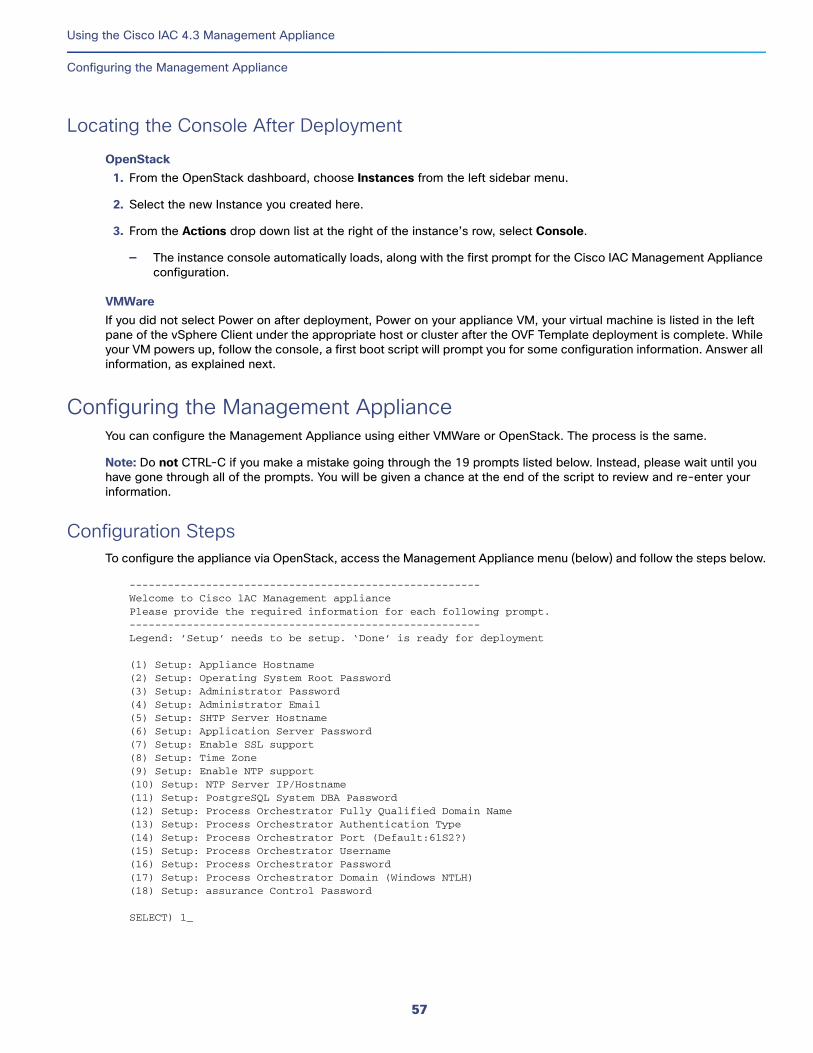
Using the Cisco IAC 4.3 Management Appliance
Configuring the Management Appliance
Locating the Console After DeploymentOpenStack
1. From the OpenStack dashboard, choose Instances from the left sidebar menu.
2. Select the new Instance you created here.
3. From the Actions drop down list at the right of the instance’s row, select Console.
— The instance console automatically loads, along with the first prompt for the Cisco IAC Management Appliance configuration.
VMWareIf you did not select Power on after deployment, Power on your appliance VM, your virtual machine is listed in the left pane of the vSphere Client under the appropriate host or cluster after the OVF Template deployment is complete. While your VM powers up, follow the console, a first boot script will prompt you for some configuration information. Answer all information, as explained next.
Configuring the Management ApplianceYou can configure the Management Appliance using either VMWare or OpenStack. The process is the same.
Note: Do not CTRL-C if you make a mistake going through the 19 prompts listed below. Instead, please wait until you have gone through all of the prompts. You will be given a chance at the end of the script to review and re-enter your information.
Configuration StepsTo configure the appliance via OpenStack, access the Management Appliance menu (below) and follow the steps below.
-------------------------------------------------------Welcome to Cisco lAC Management appliancePlease provide the required information for each following prompt.-------------------------------------------------------Legend: ’Setup’ needs to be setup. ‘Done’ is ready for deployment
(1) Setup: Appliance Hostname(2) Setup: Operating System Root Password(3) Setup: Administrator Password(4) Setup: Administrator Email(5) Setup: SHTP Server Hostname(6) Setup: Application Server Password(7) Setup: Enable SSL support(8) Setup: Time Zone(9) Setup: Enable NTP support(10) Setup: NTP Server IP/Hostname(11) Setup: PostgreSQL System DBA Password(12) Setup: Process Orchestrator Fully Qualified Domain Name(13) Setup: Process Orchestrator Authentication Type(14) Setup: Process Orchestrator Port (Default:61S2?)(15) Setup: Process Orchestrator Username(16) Setup: Process Orchestrator Password(17) Setup: Process Orchestrator Domain (Windows NTLH)(18) Setup: assurance Control Password
SELECT) 1_
57
Using the Cisco IAC 4.3 Management Appliance
Configuring the Management Appliance
1. Type 1.
(1) Setup: Appliance Hostname
a. Enter a new hostname for this virtual machine. You may enter an unqualified host name (such as “mycomputer”) or a fully-qualified domain name (such as “mycomputer.example.com”). A host name may contain letters, digits, and dashes (-).
b. Press ENTER.
Notice that the first step now says, “Done.”
(1) Done : Appliance Hostname
Note: You can re-enter the values of a “Done” item at anytime by re-choosing the item (typing its associated number) and then changing the value as needed.
2. Type 2.
(2) Setup: Operating System Root Password
c. Enter a new password for the Linux “root” superuser account.
d. Press ENTER.
e. Re-enter the password and press ENTER again.
Notice that the first step now says, “Done.”
(2) Done : Operating System Root Password
3. Type 3.
(3) Setup: Administrator Password
f. Enter a password for the Cisco IAC Management Appliance Administrator. This will also be the password for the operating system's “cisco” user.
g. Press ENTER.
h. Re-enter the password and press ENTER again.
4. Type 4.
(4) Setup: Administrator Email
a. Enter the email address for Cisco IAC Management Appliance Administrator. This is used as the sender address for all system-level email notifications.
b. Press ENTER.
5. Type 5.
(5) Setup: SMTP Server Hostname
a. Enter the hostname or IP address for the SMTP server used for sending email messages.
b. Press ENTER.
6. Type 6.
(6) Setup: Application Server Password
58
Using the Cisco IAC 4.3 Management Appliance
Configuring the Management Appliance
c. Enter a password for the application server.
d. Press ENTER.
e. Re-enter the password and press ENTER again.
7. Type 7.
(7) Setup: Enable SSL Support
a. Enter Y or Yes to enable SSL support. A self-signed certificate will be generated.
Note: The self-signed SSL certificate can be replaced with a valid SSL certificate after the Cisco IAC Management Appliance has been deployed.
b. Press ENTER.
8. Type 8.
(8) Setup: Time Zone
a. Enter the time zone in UTC (Universal Time Code) format, such as “UTC-5” for Eastern Time. This is sometimes also referred to as GMT, or Greenwich Mean Time.
Note: You must include the text, UTC, as well as the number of hours either before or after the Prime Meridian, as a negative (-) or positve (+) number. There should be no spaces. For example, UTC+8. For additional help, see https://en.wikipedia.org/wiki/List_of_UTC_time_offsets.
b. Press ENTER.
9. Type 9.
(9) Setup: Enable NTP Support
a. Enter Y or Yes to enable the NTP client.
b. Press ENTER.
10. Type 10.
(10) Setup: NTP Server IP/Hostname
a. Enter the IP address or host name for your NTP server.
Note: Leave this option blank if NTP is not enabled above or a value is supplied by your DHCP server. This value will be overridden by the NTP server supplied by your DHCP server.
b. Press ENTER.
11. Type 11.
(11) Setup: PostgreSQL System DBA Password
Note: The Management Appliance's credential manager uses a PostgreSQL database.
a. Enter a password for the database administrative accounts (“postgres”). Alphanumeric characters only.
b. Press ENTER.
c. Re-enter the password and press ENTER again.
59
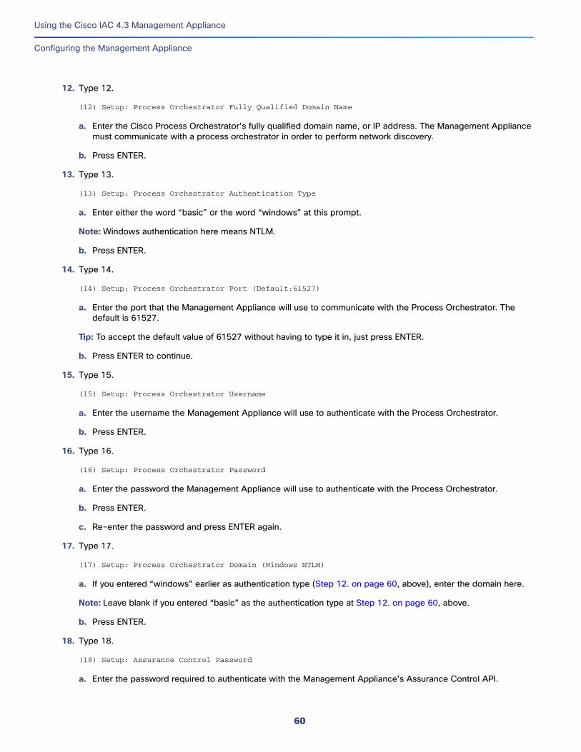
Using the Cisco IAC 4.3 Management Appliance
Configuring the Management Appliance
12. Type 12.
(12) Setup: Process Orchestrator Fully Qualified Domain Name
a. Enter the Cisco Process Orchestrator’s fully qualified domain name, or IP address. The Management Appliance must communicate with a process orchestrator in order to perform network discovery.
b. Press ENTER.
13. Type 13.
(13) Setup: Process Orchestrator Authentication Type
a. Enter either the word “basic” or the word “windows” at this prompt.
Note: Windows authentication here means NTLM.
b. Press ENTER.
14. Type 14.
(14) Setup: Process Orchestrator Port (Default:61527)
a. Enter the port that the Management Appliance will use to communicate with the Process Orchestrator. The default is 61527.
Tip: To accept the default value of 61527 without having to type it in, just press ENTER.
b. Press ENTER to continue.
15. Type 15.
(15) Setup: Process Orchestrator Username
a. Enter the username the Management Appliance will use to authenticate with the Process Orchestrator.
b. Press ENTER.
16. Type 16.
(16) Setup: Process Orchestrator Password
a. Enter the password the Management Appliance will use to authenticate with the Process Orchestrator.
b. Press ENTER.
c. Re-enter the password and press ENTER again.
17. Type 17.
(17) Setup: Process Orchestrator Domain (Windows NTLM)
a. If you entered “windows” earlier as authentication type (Step 12. on page 60, above), enter the domain here.
Note: Leave blank if you entered “basic” as the authentication type at Step 12. on page 60, above.
b. Press ENTER.
18. Type 18.
(18) Setup: Assurance Control Password
a. Enter the password required to authenticate with the Management Appliance's Assurance Control API.
60
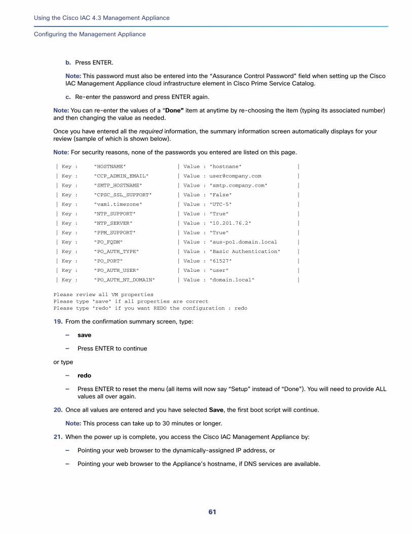
Using the Cisco IAC 4.3 Management Appliance
Configuring the Management Appliance
b. Press ENTER.
Note: This password must also be entered into the “Assurance Control Password” field when setting up the Cisco IAC Management Appliance cloud infrastructure element in Cisco Prime Service Catalog.
c. Re-enter the password and press ENTER again.
Note: You can re-enter the values of a “Done” item at anytime by re-choosing the item (typing its associated number) and then changing the value as needed.
Once you have entered all the required information, the summary information screen automatically displays for your review (sample of which is shown below).
Note: For security reasons, none of the passwords you entered are listed on this page.
Please review all VM propertiesPlease type "save" if all properties are correctPlease type "redo" if you want REDO the configuration : redo
19. From the confirmation summary screen, type:
— save
— Press ENTER to continue
or type
— redo
— Press ENTER to reset the menu (all items will now say “Setup” instead of “Done”). You will need to provide ALL values all over again.
20. Once all values are entered and you have selected Save, the first boot script will continue.
Note: This process can take up to 30 minutes or longer.
21. When the power up is complete, you access the Cisco IAC Management Appliance by:
— Pointing your web browser to the dynamically-assigned IP address, or
— Pointing your web browser to the Appliance’s hostname, if DNS services are available.
| Key : "HOSTNAME" | Value : "hostnane" |
| Key : "CCP_ADMIN_EMAIL" | Value : [email protected] |
| Key : "SMTP_HOSTNAME" | Value : "smtp.company.com" |
| Key : "CPSC_SSL_SUPPORT" | Value : "False" |
| Key : "vami.timezone" | Value : "UTC-5" |
| Key : "NTP_SUPPORT" | Value : "True" |
| Key : "NTP_SERVER" | Value : "10.201.76.2" |
| Key : "PPM_SUPPORT" | Value : "True" |
| Key : "PO_FQDM" | Value : "aus-po1.domain.local |
| Key : "PO_AUTH_TYPE" | Value : "Basic Authentication" |
| Key : "PO_PORT" | Value : "61527" |
| Key : "PO_AUTH_USER" | Value : "user" |
| Key : "PO_AUTH_NT_DOMAIN" | Value : "domain.local" |
61
Using the Cisco IAC 4.3 Management Appliance
Setting up the RabbitMQ Server for PPM Integration
Setting up the RabbitMQ Server for PPM Integration
Creating a New Virtual HostYou create a /PPM virtual host by logging in to the RabbitMQ server on your Cisco IAC Management Appliance with your Cisco credentials.
1. Start the RabbitMQ server.
2. Go to Admin > Virtual Hosts.
3. Create a new vhost called, “/PPM”.
Adding Users to the RabbitMQ Server1. Go to Admin > Users.
2. Create a new user called, “ppm.”
3. Give this new user “ppm” permission to use/access the “/PPM” vhost.
Note: You can also give the user, “cisco” permission to use/access the “/PPM” vhost, as well. However, this step is not required if you will be using the Cisco IAC Management Appliance.
Creating the PPM Exchange1. Click the Exchanges tab.
2. Add a new exchange called, “ppm.alarms.exchange”.
3. Add this exchange only to the new “/PPM” vhost you created.
Creating the PPM Queue1. Click the Queues tab.
2. Add a new queue named, “ppm_alarms_queue” under the /PPM vhost.
Configuring the Binding1. Click the Exchanges tab.
2. Choose the ppm.alarms.exchange.
3. Choose Bindings.
4. Under Bindings, create a new binding to ppm_alarms_queue using the routing key ppm-alarm-routing-key.
Making Changes on the PPM Server1. Login (ssh) to the PPM server as root.
2. Go to vi /opt/CSCOppm-unit/properties/System.properties.
a. Set TCA_USE_OLD_MSG_FORMAT = true.
b. Save changes.
62
Using the Cisco IAC 4.3 Management Appliance
Changing the AMPQ Barbican Secret for PPM Users
3. Go to vi /opt/CSCOppm-gw/properties/System.properties.
a. Set TCA_USE_OLD_MSG_FORMAT = true.
b. Save changes.
4. Reboot PPM server.
5. Login to the PPM server web page as sys admin.
6. Go to Administration > Alarms/Events Editor.
7. Choose Add AMQP Connection.
8. Create a new AMQP connection with parameters matching those you just configured on the RabbitMQ server side, above.
9. Click OK.
Note: Connection should be in the “Active” state.
Changing the AMPQ Barbican Secret for PPM Users1. Login (ssh) to your server as root.
2. Retrieve the current randomly-generated value of the Assurance Control Password set for Barbican by running the following command:
cat /opt/cisco/assurancecontrol/webapp/assurancecontrol/authentication/key.txt
You should see the following:
[root@iac-ma-43-centOS-b23 ~]# cat /opt/cisco/assurancecontrol/webapp/assurancecontrol/authentication/key.txt
{"username":"assurancecontrol","password":"<current_key_displays_here>" , "tenant":"assurancecontrol"}[root@iac-ma-43-centOS-b23 ~]#
3. Retrieve secret URL for AMQP.
barbican --os-auth-url=http://localhost:5000/v2.0 --os-username assurancecontrol --os-password "<current_pw_displays_here>" --os-tenant-name assurancecontrol secret list --name amqp
You should see the following:
root@iac-ma-43-centOS-b23 ~]# barbican --os-auth-url=http://localhost:5000/v2.0 --os-username assurancecontrol --os-password "<current_pw_displays_here>" --os-tenant-name assurancecontrol secret list --name amqpSecret - href: http://localhost:9311/v1/5e303415b0fb4606b61edc5aada0b06d/secrets/114634bd-1186-427e-b274-78ad562ddf24 name: amqp created: 2015-10-22 22:02:13.674213+00:00 status: ACTIVE content types: {'default': 'text/plain'} algorithm: None bit length: None mode: None expiration: None
secrets displayed: 1 - offset: 0
63
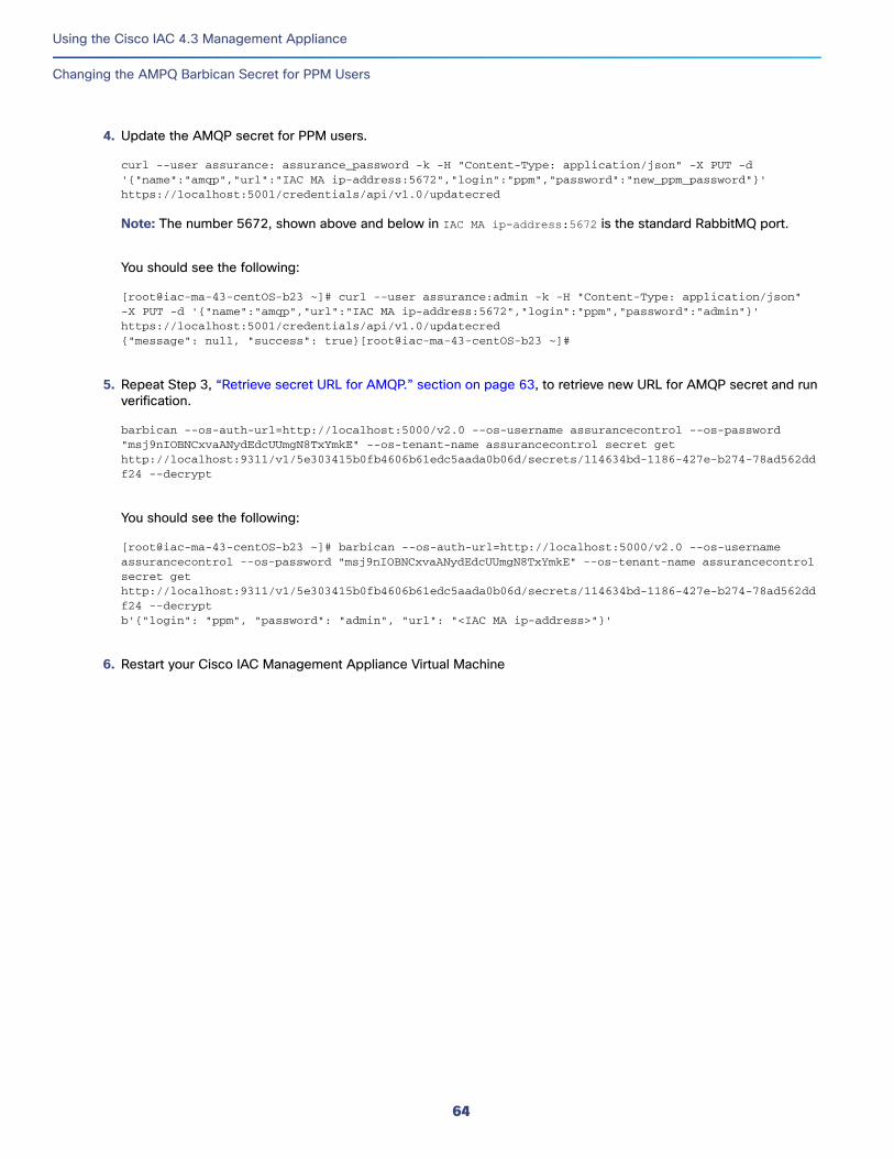
Using the Cisco IAC 4.3 Management Appliance
Changing the AMPQ Barbican Secret for PPM Users
4. Update the AMQP secret for PPM users.
curl --user assurance: assurance_password -k -H "Content-Type: application/json" -X PUT -d '{"name":"amqp","url":"IAC MA ip-address:5672","login":"ppm","password":"new_ppm_password"}' https://localhost:5001/credentials/api/v1.0/updatecred
Note: The number 5672, shown above and below in IAC MA ip-address:5672 is the standard RabbitMQ port.
You should see the following:
[root@iac-ma-43-centOS-b23 ~]# curl --user assurance:admin -k -H "Content-Type: application/json" -X PUT -d '{"name":"amqp","url":"IAC MA ip-address:5672","login":"ppm","password":"admin"}' https://localhost:5001/credentials/api/v1.0/updatecred{"message": null, "success": true}[root@iac-ma-43-centOS-b23 ~]#
5. Repeat Step 3, “Retrieve secret URL for AMQP.” section on page 63, to retrieve new URL for AMQP secret and run verification.
barbican --os-auth-url=http://localhost:5000/v2.0 --os-username assurancecontrol --os-password "msj9nIOBNCxvaANydEdcUUmgN8TxYmkE" --os-tenant-name assurancecontrol secret get http://localhost:9311/v1/5e303415b0fb4606b61edc5aada0b06d/secrets/114634bd-1186-427e-b274-78ad562ddf24 --decrypt
You should see the following:
[root@iac-ma-43-centOS-b23 ~]# barbican --os-auth-url=http://localhost:5000/v2.0 --os-username assurancecontrol --os-password "msj9nIOBNCxvaANydEdcUUmgN8TxYmkE" --os-tenant-name assurancecontrol secret get http://localhost:9311/v1/5e303415b0fb4606b61edc5aada0b06d/secrets/114634bd-1186-427e-b274-78ad562ddf24 --decryptb'{"login": "ppm", "password": "admin", "url": "<IAC MA ip-address>"}'
6. Restart your Cisco IAC Management Appliance Virtual Machine
64
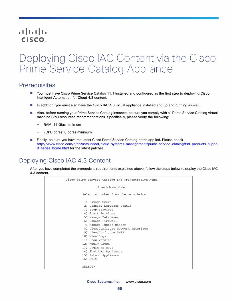
Deploying Cisco IAC Content via the Cisco Prime Service Catalog AppliancePrerequisites
You must have Cisco Prime Service Catalog 11.1 installed and configured as the first step to deploying Cisco Intelligent Automation for Cloud 4.3 content.
In addition, you must also have the Cisco IAC 4.3 virtual appliance installed and up and running as well.
Also, before running your Prime Service Catalog instance, be sure you comply with all Prime Service Catalog virtual machine (VM) resources recommendations. Specifically, please verify the following:
— RAM: 16 Gigs minimum
— vCPU cores: 8 cores minimum
Finally, be sure you have the latest Cisco Prime Service Catalog patch applied. Please check http://www.cisco.com/c/en/us/support/cloud-systems-management/prime-service-catalog/tsd-products-support-series-home.html for the latest patches.
Deploying Cisco IAC 4.3 ContentAfter you have completed the prerequisite requirements explained above, follow the steps below to deploy the Cisco IAC 4.3 content.
Cisco Prime Service Catalog and Orchestration Menu
Standalone Node
Select a number from the menu below
_1) Manage Users_2) Display Services Status_3) Stop Services_4) Start Services_5) Manage Databases_6) Manage Firewall_7) Manage Puppet Master_8) View/Configure Network Interface_9) View/Configure SMTP10) View Logs11) Show Version12) Apply Patch13) Login as Root14) Shutdown Appliance15) Reboot Appliance16) Quit
SELECT>
65
Cisco Systems, Inc. www.cisco.com
Deploying Cisco IAC Content via the Cisco Prime Service Catalog Appliance
Deploying Cisco IAC 4.3 Content
1. Login to the Linux operating system as the shelladmin user.
Note: You can do this via the VM Console in your vSphere Client, or via an SSH connection to the IP address of the virtual machine (VM).
2. On the Linux Login Prompt, type shelladmin for the user name, and enter the password.
3. To deploy the Cisco IAC 4.3 content, you will be using the Apply Patch option.
a. Enter 12 at the SELECT> prompt and press ENTER.
4. You will see the following message:
This will apply a patch to the Cisco Prime Service Catalog and Orchestration Virtual Appliance.
All Prime Service Catalog and Orchestration Services will be shutdown, andthe appliance may be required to reboot after the patch has been installed.
Please ensure all users of Prime Service Catalog are logged out, or anyactive work may be lost.
IMPORTANT: You should ensure you have recent backups of your Prime Service Catalogand Orchestration databases before continuing.
Proceed with applying patch? (y/n):
a. Press Y to continue.
5. Enter the URL to the Cisco IAC 4.3 Content archive file and press Enter. The file is located on the Cisco website and you should have previously downloaded it from cisco.com. The file name should follow this pattern:
IAC4.3.#-For-PSC11.#-Appliance_#####.zip
Note: Please make sure your URL is a valid one.
Note: Cisco Process Orchestrator 11.1 for now supports only the “http” protocol. Also, do not use “file” or “ftp.” This is a limitation of Prime Service Catalog.
6. You will see progress information displayed on your screen, including a number of prompts.
a. Press Y to continue when prompted.
b. Enter your Oracle SID when prompted.
c. Enter your Oracle PSC user.
d. Enter the password for the Oracle Database PSC user.
e. Retype the above password.
f. Enter a value for the PSC Admin user (the default is “admin”).
g. Enter the password for the PSC Admin user.
h. Retype the above password.
Note: The process will take about an hour to an hour and a half to complete the import/deploy procedure.
66
Deploying Cisco IAC Content via the Cisco Prime Service Catalog Appliance
Deploying Cisco IAC 4.3 Content
Final StepsAt the end of this procedure, the screen will update. You must review all lines that say, “actionResult=”.
1. Make sure that all the results list “Success”.
2. Next, run the following command on Prime Service Catalog :
cd /opt/cisco/psc/automation/logs/
3. Then, run Run the following command on Prime Service Catalog:
ls – la
You will see this information display.
-rw-rw-r--. 1 cisco cisco 571 Aug 19 08:47 CdApi_2.log-rw-rw-r--. 1 cisco cisco 480 Aug 19 08:50 CdApi_3.log-rw-rw-r--. 1 cisco cisco 496 Aug 19 09:04 CdApi_4.log-rw-rw-r--. 1 cisco cisco 413 Aug 19 09:04 CdApi_5.log-rw-rw-r--. 1 cisco cisco 480 Aug 19 09:55 CdApi_6.log-rw-rw-r--. 1 cisco cisco 15584 Aug 19 08:47 PortalApi_1.log
Reviewing the LogsEvery log contains info about the status of /import/deploy procedure. All logs has a number in it. Customer has to review 1,2,3... 6, etc. For example, the service package Import, which is log #5, looks like this:
[2015-0#-## 09:03:55] [INFO] Automation job is initiated by 'admin admin'
[2015-08-19 09:03:55] [INFO] Process started for action: import, package: SC_Services_4-3.xml[2015-08-19 09:04:03] [INFO] Success for action: import, package: SC_Services_4-3[2015-08-19 09:04:03] [INFO] Success details: File '/opt/cisco/psc/automation/import/SC_Services_4-3.xml', Package 'SC_Services_4-3' imported successfully.[2015-08-19 09:04:03] [INFO] Process ended for action: import, package: SC_Services_4-3
By reviewing the above information, we can see that the deployment was successful.
Important: Make certain to check all logs to ensure everything has imported/deployed successfully.
About the Localization FileFor information on deploying the US English Localization file, see the module Upgrading From Cisco IAC 4.1.1 or 4.2, Post-Upgrade Tasks, under the heading, Importing US English Localization File.
Note: When importing/deploying Cisco IAC using option 12 on the Cisco Prime Service Catalog and Orchestration Menu, Standalone Node (see Deploying Cisco IAC 4.3 Content, page 65, for a look at the menu), please make sure you deploy localization after that by using the available UI (user interface) functionality.
Note: Localization is imported, but not deployed, by default.
67

Deploying Cisco IAC Content via the Cisco Prime Service Catalog Appliance
Deploying Cisco IAC 4.3 Content
68
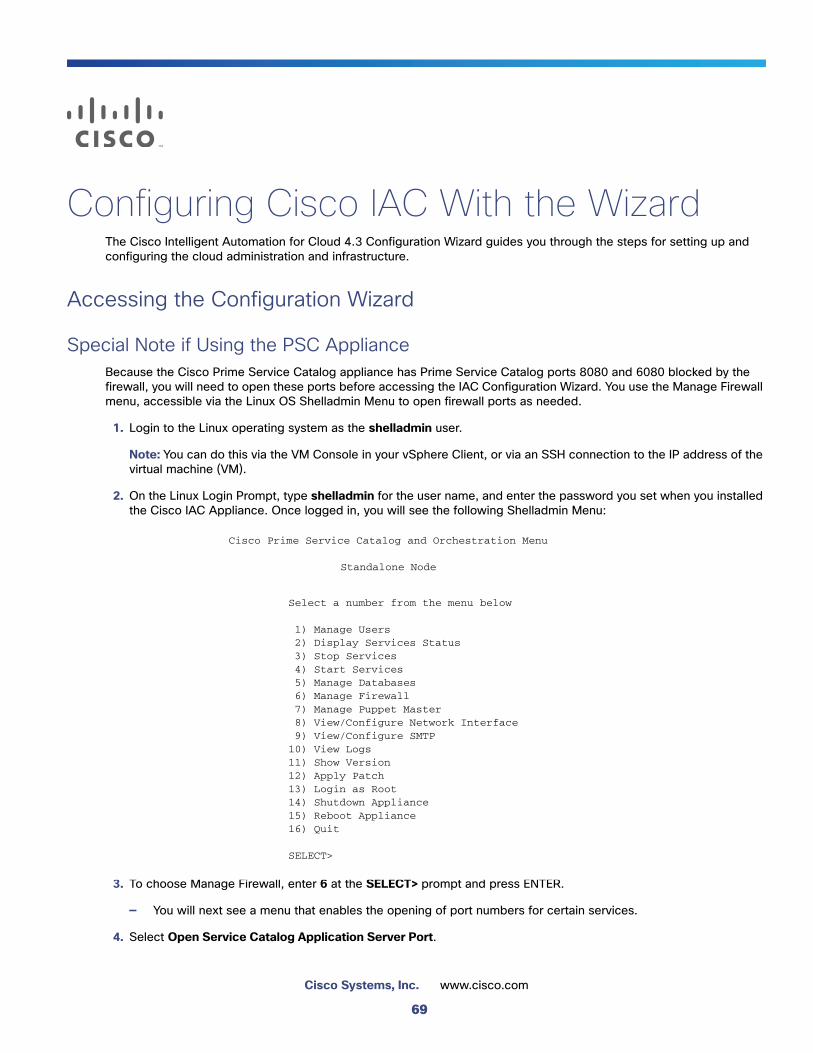
Configuring Cisco IAC With the WizardThe Cisco Intelligent Automation for Cloud 4.3 Configuration Wizard guides you through the steps for setting up and configuring the cloud administration and infrastructure.
Accessing the Configuration Wizard
Special Note if Using the PSC ApplianceBecause the Cisco Prime Service Catalog appliance has Prime Service Catalog ports 8080 and 6080 blocked by the firewall, you will need to open these ports before accessing the IAC Configuration Wizard. You use the Manage Firewall menu, accessible via the Linux OS Shelladmin Menu to open firewall ports as needed.
1. Login to the Linux operating system as the shelladmin user.
Note: You can do this via the VM Console in your vSphere Client, or via an SSH connection to the IP address of the virtual machine (VM).
2. On the Linux Login Prompt, type shelladmin for the user name, and enter the password you set when you installed the Cisco IAC Appliance. Once logged in, you will see the following Shelladmin Menu:
3. To choose Manage Firewall, enter 6 at the SELECT> prompt and press ENTER.
— You will next see a menu that enables the opening of port numbers for certain services.
4. Select Open Service Catalog Application Server Port.
Cisco Prime Service Catalog and Orchestration Menu
Standalone Node
Select a number from the menu below
_1) Manage Users_2) Display Services Status_3) Stop Services_4) Start Services_5) Manage Databases_6) Manage Firewall_7) Manage Puppet Master_8) View/Configure Network Interface_9) View/Configure SMTP10) View Logs11) Show Version12) Apply Patch13) Login as Root14) Shutdown Appliance15) Reboot Appliance16) Quit
SELECT>
69
Cisco Systems, Inc. www.cisco.com
Configuring Cisco IAC With the Wizard
Accessing the Configuration Wizard
5. Select Open Service Link Application Server Port.
6. Select Quit and then select Quit at the Shelladmin menu.
Starting the Configuration Wizard1. Open a browser and launch Cisco Prime Service Catalog.
2. Log in as a Site Administrator.
3. To access the Cisco Intelligent Automation for Cloud Configuration Wizard:
a. Choose Service Portal from the menu at the top right of the screen.
b. Choose Setup from the Cisco IAC 4.3 menu
c. Choose Configuration Wizard from the Setup sub-menu.
4. The Configuration Wizard for Cisco IAC 4.3 displays.
The Wizard Welcome Screen
Setting the Custom Styles DirectoryNote: If you are configuring IAC using the IAC Virtual Appliance, you can skip this section and proceed to Configuring Agent Properties, page 71.
Verify that Cisco IAC is chosen and that Site Administration is associated with this style. To do so, complete these steps.
1. Click the Set Custom Styles Directory link on the Welcome tab on the Cisco IAC 4.3 Config Wizard.
2. Click Custom Styles in the right menu (it may already be selected).
3. In the Name field, enter Cisco Intelligent Automation for Cloud 4.3.
4. Check the Make this Style the default for the entire site check box.
5. Check the Apply this Style to Service Catalog check box.
6. On the Style Directory field, click Browse.
7. Click the IAC radio button.
8. Click OK.
9. Click Add (it is located toward the bottom middle of the screen) to open the Custom Style Properties window.
10. On the Custom Style Properties pop-up window, click Search to browse for the organizational units to which to associate the custom style properties.
11. Close the popup window and close the Custom Styles window to return to the Configuration Wizard.
Note: The Administration page of the Cisco Prime Service Catalog works only on specific browsers. See the Cisco Prime Service Catalog Compatibility Matrix for more information. The latest version of the documentation can be found here: http://www.cisco.com/c/en/us/support/cloud-systems-management/prime-service-catalog-10-0/model.html#InstallandUpgradeGuides
70
Configuring Cisco IAC With the Wizard
Configuring Agent Properties
Configuring Agent PropertiesOn the STEP 1 panel of the Cisco Intelligent Automation for Cloud Configuration Wizard, you configure agent properties for all REX agents and HTTP agents.
Note: Instructions on how to create the REX Agent and nsAPI accounts also appear elsewhere in this manual. So, if you have already done so, you can skip that step now.
Creating Service Accounts for Both REX Agent and nsAPI UsersService accounts for the REX adapter and nsAPI are required to connect Cisco Prime Service Catalog to the REX adapter and Process Orchestrator, respectively.
Note: You need to be logged in as a site administrator to complete the steps in this section.
Creating the Service Accounts for REX Agent and nsAPI Users1. From the Wizard, choose Create service accounts for both REX Agent and nsAPI users.
2. On the Organization Designer page, click Create Person from the Common Tasks panel (on the left of the screen).
3. On the Create Person form, set up the REX user:
a. Enter “REX” as the First Name and “User” as the Last Name.
b. Enter a valid, actively monitored e-mail address. This will be the address where notifications relating to the REX adapter user account will be sent.
Note: Consider using the email address of a CPTA or a distribution list for all CPTAs.
c. Choose (GMT) Greenwich Mean Time from the drop-down list.
d. In the current release, only US English is supported; any language selection you make will be ignored
Note: If you are using the Cisco IAC Virtual Appliance, some or all of this information may have been entered for you.
e. Browse to choose an Organizational Unit. Click Search, click the Site Administration radio button, then click Add.
f. Optional. Enter a description or any information pertinent to the user account in the Notes field.
g. Enter REXuser as the Login.
h. Enter, then enter re-enter (to confirm) the password for the REX user account.
4. Click Create to create the new user.
Note: Once the user has been created, the People tab contents should automatically display, showing the user information you just entered. If you need to make corrections, make them before proceeding to the next step.
Creating the Service Account for nsAPI User Note: This step is optional if you intend to enable Directory Integration.
1. Back on Organization Designer page, choose the People tab at the top of the page, if necessary.
2. Click Copy (upper right of the screen) to create a copy of the REX user that will be named “nsAPI User”.
Note: If you are using the Virtual Appliance, this information may have been entered for you.
3. On the Create Person form:
71

Configuring Cisco IAC With the Wizard
Configuring Agent Properties
a. Enter “nsAPI” as the First Name and “User” as the Last Name.
b. Enter a valid, actively monitored e-mail address. This will be the address where notifications relating to the nsAPI user account will be sent.
Note: Consider using the email address of a CPTA or a DL for all CPTAs.
c. Choose (GMT) Greenwich Mean Time from the drop-down list if it is not already filled in.
d. As before, only US English is supported; any language selection you make will be ignored.
e. Browse to open the Choose an Organizational Unit dialog box.
f. Click Search.
g. Click the Site Administration radio button
h. Click the People tab and then click Add.
i. Enter nsAPI as the Login.
j. Enter, then confirm password for the nsAPI user account you created earlier.
k. Click Create to close the form.
You will be returned to the Organization Designer.
Setting the Calendar for the nsAPI User1. In Organization Designer, click to access, or ensure that you are on, the People tab.
2. In the People pane on the left side of the window, locate the line and click the name nsAPI user record.
3. From the menu on the right side of the page, choose Calendar:
4. In the Calendar pane, change all time values in the To column to 11:59 PM.
5. Change times in the From column to 12:00 AM if not already done so (as it is for Sunday/Saturday).
Note: By default, Monday through Friday start at 9:00 AM, making for a 24-hour calendar.
6. Click Update.
7. When your are done, click Close in the pop up window.
You will be returned to your location on the Wizard.
Setting Username and Password for ‘REX Set REX Agent Properties’1. From the Wizard, choose Set username and password for the 'REX Set REX Agent Properties' agent
2. In the Agents pane on the left, expand REX Set REX Agent Properties.
3. Click Outbound Properties.
4. In the REXOutboundAdapter.Username field, enter the REX login name you created on the Create Person form.
5. In the REXOutboundAdapter.Password field, enter the REX password in the Create Person form.
6. Click Save.
7. Click Close.
You will be returned to your location on the Wizard.
72
Configuring Cisco IAC With the Wizard
Configuring Agent Properties
Starting the REX Set REX Agent Properties Agent1. From the Wizard, choose Start 'REX Set REX Agent Properties' agent
Note: If you do not see “REX Set REX Agent Properties” in the list, scroll down or use the pagination at the bottom to navigate to the other pages. Or, sort by agent name by clicking the Name column heading.
2. Click the red icons next to REX Set REX Agent Properties.
3. Click the Start Selected button up at the top right corner of the page.
— The red icons turn to green, indicating that they are now sending and receiving.
Note: In some cases, you may need to refresh the page before you see the colors change. To do so, click the Refresh icon.
4. Close AFC.
Setting REX Agent ConfigurationConfigure all of the REX agent properties, then verify that the agents are configured correctly.
1. From the Wizard, choose Set REX Agent Configuration
2. On the Set REX Agent Configuration form, enter the REX account login name, then enter and re-enter the REX account password.
3. Enter the URL to the Prime Service Catalog Request Center server in the Cloud Portal Request Center URL field.
Note: The URL should include http or https, the hostname and port number, and the pathname to ServiceCatalog. For example, http://localhost:8080/ServiceCatalog.
4. Click Submit Order to submit the form and display the Order Confirmation page for the service that you ordered.
5. Click on the number in the Requisition Number field to display the details.
6. In the Requisition Details pane, click the requisition number in the Requisition Number field to refresh the status.
Note: Repeat this refresh process as many times as needed until the status is Completed.
7. Click Close to return to the Configuration Wizard.
Starting All REX AgentsYou will next start all REX agents; that is, all agents with REX in the name. The current list includes the following eleven REX agents:
REX Add Organization Unit
REX Add Organization Unit (Tenant)
REX Add Person
REX Create Queue
REX Deactivate OU
REX Delete Queue
REX Modify Organization Unit
73
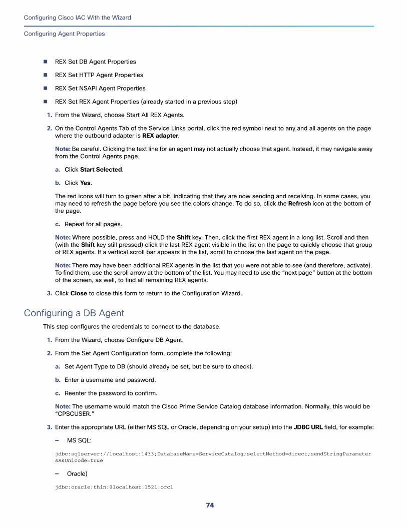
Configuring Cisco IAC With the Wizard
Configuring Agent Properties
REX Set DB Agent Properties
REX Set HTTP Agent Properties
REX Set NSAPI Agent Properties
REX Set REX Agent Properties (already started in a previous step)
1. From the Wizard, choose Start All REX Agents.
2. On the Control Agents Tab of the Service Links portal, click the red symbol next to any and all agents on the page where the outbound adapter is REX adapter.
Note: Be careful. Clicking the text line for an agent may not actually choose that agent. Instead, it may navigate away from the Control Agents page.
a. Click Start Selected.
b. Click Yes.
The red icons will turn to green after a bit, indicating that they are now sending and receiving. In some cases, you may need to refresh the page before you see the colors change. To do so, click the Refresh icon at the bottom of the page.
c. Repeat for all pages.
Note: Where possible, press and HOLD the Shift key. Then, click the first REX agent in a long list. Scroll and then (with the Shift key still pressed) click the last REX agent visible in the list on the page to quickly choose that group of REX agents. If a vertical scroll bar appears in the list, scroll to choose the last agent on the page.
Note: There may have been additional REX agents in the list that you were not able to see (and therefore, activate). To find them, use the scroll arrow at the bottom of the list. You may need to use the “next page” button at the bottom of the screen, as well, to find all remaining REX agents.
3. Click Close to close this form to return to the Configuration Wizard.
Configuring a DB AgentThis step configures the credentials to connect to the database.
1. From the Wizard, choose Configure DB Agent.
2. From the Set Agent Configuration form, complete the following:
a. Set Agent Type to DB (should already be set, but be sure to check).
b. Enter a username and password.
c. Reenter the password to confirm.
Note: The username would match the Cisco Prime Service Catalog database information. Normally, this would be “CPSCUSER.”
3. Enter the appropriate URL (either MS SQL or Oracle, depending on your setup) into the JDBC URL field, for example:
— MS SQL:
jdbc:sqlserver://localhost:1433;DatabaseName=ServiceCatalog;selectMethod=direct;sendStringParametersAsUnicode=true
— Oracle)
jdbc:oracle:thin:@localhost:1521:orcl
74
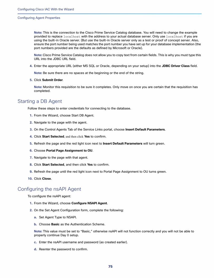
Configuring Cisco IAC With the Wizard
Configuring Agent Properties
Note: This is the connection to the Cisco Prime Service Catalog database. You will need to change the example provided to replace localhost with the address to your actual database server. Only use localhost if you are using the built-in Oracle server. (But use the built-in Oracle server only as a test or proof of concept server. Also, ensure the port number being used matches the port number you have set up for your database implementation (the port numbers provided are the defaults as defined by Microsoft or Oracle).
Note: Cisco Prime Service Catalog does not allow you to copy text from certain fields. This is why you must type this URL into the JDBC URL field.
4. Enter the appropriate URL (either MS SQL or Oracle, depending on your setup) into the JDBC Driver Class field.
Note: Be sure there are no spaces at the beginning or the end of the string.
5. Click Submit Order.
Note: Monitor this requisition to be sure it completes. Only move on once you are certain that the requisition has completed.
Starting a DB AgentFollow these steps to enter credentials for connecting to the database.
1. From the Wizard, choose Start DB Agent.
2. Navigate to the page with the agent.
3. On the Control Agents Tab of the Service Links portal, choose Insert Default Parameters.
4. Click Start Selected, and then click Yes to confirm.
5. Refresh the page and the red light icon next to Insert Default Parameters will turn green.
6. Choose Portal Page Assignment to OU.
7. Navigate to the page with that agent.
8. Click Start Selected, and then click Yes to confirm.
9. Refresh the page until the red light icon next to Portal Page Assignment to OU turns green.
10. Click Close.
Configuring the nsAPI AgentTo configure the nsAPI agent:
1. From the Wizard, choose Configure NSAPI Agent.
2. On the Set Agent Configuration form, complete the following:
a. Set Agent Type to NSAPI.
b. Choose Basic as the Authentication Scheme.
Note: This value must be set to “Basic,” otherwise nsAPI will not function correctly and you will not be able to properly continue Day 0 setup.
c. Enter the nsAPI username and password (as created earlier).
d. Reenter the password to confirm.
75
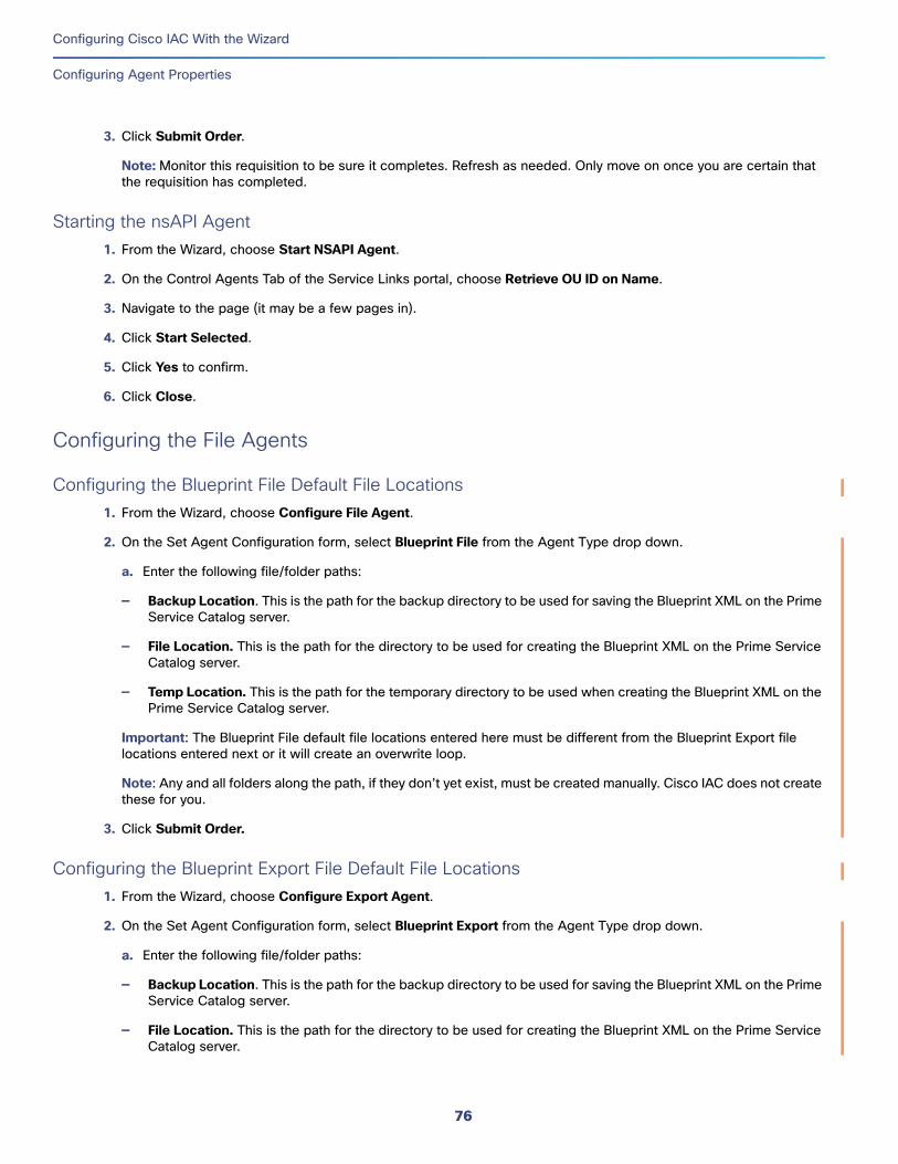
Configuring Cisco IAC With the Wizard
Configuring Agent Properties
3. Click Submit Order.
Note: Monitor this requisition to be sure it completes. Refresh as needed. Only move on once you are certain that the requisition has completed.
Starting the nsAPI Agent 1. From the Wizard, choose Start NSAPI Agent.
2. On the Control Agents Tab of the Service Links portal, choose Retrieve OU ID on Name.
3. Navigate to the page (it may be a few pages in).
4. Click Start Selected.
5. Click Yes to confirm.
6. Click Close.
Configuring the File Agents
Configuring the Blueprint File Default File Locations1. From the Wizard, choose Configure File Agent.
2. On the Set Agent Configuration form, select Blueprint File from the Agent Type drop down.
a. Enter the following file/folder paths:
— Backup Location. This is the path for the backup directory to be used for saving the Blueprint XML on the Prime Service Catalog server.
— File Location. This is the path for the directory to be used for creating the Blueprint XML on the Prime Service Catalog server.
— Temp Location. This is the path for the temporary directory to be used when creating the Blueprint XML on the Prime Service Catalog server.
Important: The Blueprint File default file locations entered here must be different from the Blueprint Export file locations entered next or it will create an overwrite loop.
Note: Any and all folders along the path, if they don’t yet exist, must be created manually. Cisco IAC does not create these for you.
3. Click Submit Order.
Configuring the Blueprint Export File Default File Locations1. From the Wizard, choose Configure Export Agent.
2. On the Set Agent Configuration form, select Blueprint Export from the Agent Type drop down.
a. Enter the following file/folder paths:
— Backup Location. This is the path for the backup directory to be used for saving the Blueprint XML on the Prime Service Catalog server.
— File Location. This is the path for the directory to be used for creating the Blueprint XML on the Prime Service Catalog server.
76
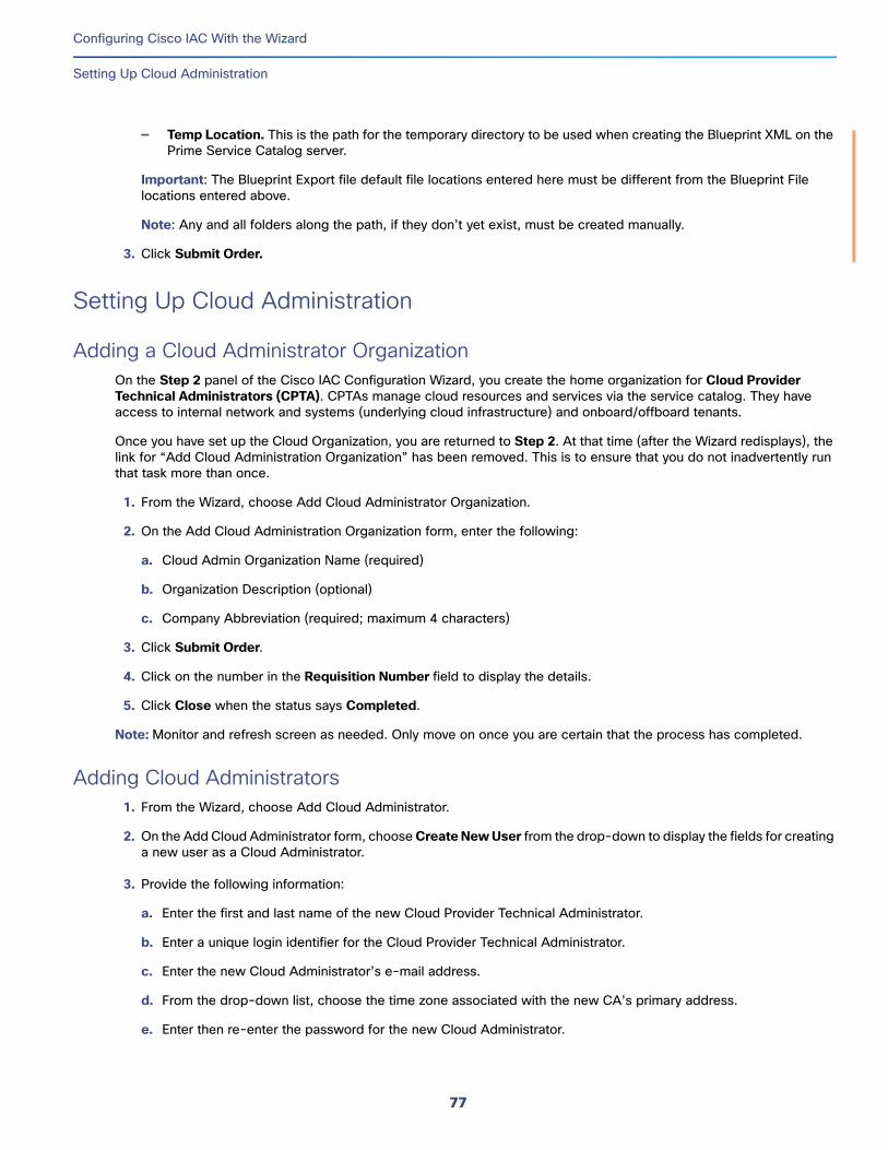
Configuring Cisco IAC With the Wizard
Setting Up Cloud Administration
— Temp Location. This is the path for the temporary directory to be used when creating the Blueprint XML on the Prime Service Catalog server.
Important: The Blueprint Export file default file locations entered here must be different from the Blueprint File locations entered above.
Note: Any and all folders along the path, if they don’t yet exist, must be created manually.
3. Click Submit Order.
Setting Up Cloud Administration
Adding a Cloud Administrator OrganizationOn the Step 2 panel of the Cisco IAC Configuration Wizard, you create the home organization for Cloud Provider Technical Administrators (CPTA). CPTAs manage cloud resources and services via the service catalog. They have access to internal network and systems (underlying cloud infrastructure) and onboard/offboard tenants.
Once you have set up the Cloud Organization, you are returned to Step 2. At that time (after the Wizard redisplays), the link for “Add Cloud Administration Organization” has been removed. This is to ensure that you do not inadvertently run that task more than once.
1. From the Wizard, choose Add Cloud Administrator Organization.
2. On the Add Cloud Administration Organization form, enter the following:
a. Cloud Admin Organization Name (required)
b. Organization Description (optional)
c. Company Abbreviation (required; maximum 4 characters)
3. Click Submit Order.
4. Click on the number in the Requisition Number field to display the details.
5. Click Close when the status says Completed.
Note: Monitor and refresh screen as needed. Only move on once you are certain that the process has completed.
Adding Cloud Administrators 1. From the Wizard, choose Add Cloud Administrator.
2. On the Add Cloud Administrator form, choose Create New User from the drop-down to display the fields for creating a new user as a Cloud Administrator.
3. Provide the following information:
a. Enter the first and last name of the new Cloud Provider Technical Administrator.
b. Enter a unique login identifier for the Cloud Provider Technical Administrator.
c. Enter the new Cloud Administrator’s e-mail address.
d. From the drop-down list, choose the time zone associated with the new CA’s primary address.
e. Enter then re-enter the password for the new Cloud Administrator.
77
Configuring Cisco IAC With the Wizard
Setting Up Cloud Administration
4. Click on the number in the Requisition Number field to display the details.
5. Click Submit Order.
6. Click Close when the status says Completed.
Note: Monitor and refresh screen as needed. Only move on once you are certain that the process has completed.
Adding Cloud Administrators: Directory Service Users OnlyThis section applies only if you are using a directory service to import user and organization data. Before you proceed, directory integration must be set up. After you set up directory integration, users are automatically imported when they log in, and their Prime Service Catalog roles are automatically assigned based on the user groups to which they were added in the directory.
User roles are assigned when you define group role mappings during directory integration setup (as shown in Adding the nsAPI User to the Cloud Administration Group, page 51).
You assign the Cloud Administrator role to a user from the directory, rather than from Cisco Prime Service Catalog, by adding the user to the Cloud Administrator user group in the directory.
Making nsAPI a Cloud Provider Technical Administrator1. From the Wizard, choose Make nsAPI a Cloud Provider Technical Administrator.
2. On the Add Cloud Administrator page, click Choose an Existing User.
3. Choose the nsAPI user and then click Submit Order. You may see a popup displays the following message:
The user you have chosen currently belongs to another organization.Assigning the Cloud Administrator role will automatically set user organization to the Cloud Administrator Organization. If you want to assign the role but not modify the Organization. you can do so through Organization Designer
4. Click on the number in the Requisition Number field to display the details.
5. Click Close when the status says Completed.
Adding Site Administrator Role to nsAPI UserIf you are using a directory service, see the information in the following section, Adding Cloud Administrators, page 77.
1. From the Wizard, Step 2, click Add Site Administrator role to nsAPI user.
2. Choose the nsAPI user.
3. Choose Roles on the right of the screen.
4. Click Add under the list of Roles first to open the search bar.
5. Search for “Site Administrator”.
6. Check the Site Administrator check box.
7. Click Add and click Close.
78
Configuring Cisco IAC With the Wizard
Setting Up Cloud Administration
Connecting Cisco Process OrchestratorHere, you register and connect the various platform elements to be used for the cloud. This setup must be completed before any further setup or usage of the cloud environment can take place.
1. From the Wizard, on Step 2, choose Connect Cisco Process Orchestrator.
2. On the Connect Cloud Infrastructure form, in the Select Platform Element Type area, select Cisco Process Orchestrator from the Platform Element Type drop down list. The form will populate with fields relevant to Process Orchestrator. Enter the following:
Cisco Cloud Portal (Cisco Prime Service Catalog) Sectiona. Enter an optional Connection Name.
b. Verify the Host Name.
c. Verify the Request Center Port and the Service Link Port.
d. Ensure that the Connection Encrypted radio button is set to False.
Note: The Use SSL is set to “False” by default. Setting to “True” requires SSL to be set up and enabled on Cisco Process Orchestrator, which is not required for Cisco IAC 4.3.
e. Enter the NSAPI username.
f. Enter the NSAPI Password.
g. Confirm the NSAPI Password.
Cisco Process Orchestrator Connection Settingsa. Enter Connection Name (optional)
a. Enter a Description (optional)
b. Verify the Host Name.
c. Verify the Process Orchestrator Port Number.
d. Enter the Process Orchestrator Administrator username.
e. Enter the Process Orchestrator Administrator Domain (if applicable).
f. Ensure Process Orchestrator Connection Encrypted option is set to False.
g. Choose the Process Orchestrator Authentication Scheme.
h. Enter the Process Orchestrator Administrator Password.
i. Select a protocol from the Protocol drop down.
j. Enter the location for Process Orchestrator in the PO Location field. This is normally the datacenter where Cisco Process Orchestrator is located. This field is mandatory.
k. Enter a Friendly Name.
l. Enter a User Name and User Domain.
m. Enter a User Password and then Confirm Password.
n. Ensure that the Connection Encrypted radio button is set to False.
79
Configuring Cisco IAC With the Wizard
Connecting to the Cloud Infrastructure
Note: The Use SSL is set to “False” by default. Setting to “True” requires SSL to be set up and enabled on Cisco Process Orchestrator, which is not required for Cisco IAC 4.3.
3. Click Submit Order.
Note: The configuration of the HTTP agents takes some time and the requisition will be waiting for agent start, which happens in the next step, Starting All Agents.
Starting All AgentsFinally, you need to start all of the other agents in order to successfully finish this procedure. Wait for at least two minutes before starting this step.
1. From the Wizard, choose Start all other agents.
2. On the Control Agents Tab of the Service Links portal, choose every single agent on every page with a red light icon.
3. Click Start Selected, and then click Yes to confirm.
4. The red light icon next to all the remaining agents will turn green. To see if they turn green, click Refresh (bottom right corner) to check the new status.
Note: There may have been additional agents in the list that you were not able to see (and therefore, activate). To find agents, use the scroll arrow at the bottom of the list or the “next page” button at the bottom of the screen.
5. Click Close when completed.
Initializing Cisco IAC Licensing1. From the Wizard, choose Initialize licensing.
2. Click Submit Order.
3. Click on the number in the Requisition Number field to display the details.
4. Click Close when the status says Completed.
Connecting to the Cloud Infrastructure On the STEP 3 panel of the Configuration Wizard, you define the connection information for the platform elements that will be used in Cisco IAC. This information will be used by Cisco Process Orchestrator to integrate with the various components involved in the cloud provisioning processes.
Note: This step needs to be repeated multiple times for each Platform Element Infrastructure item with which you intend to connect.
1. Log out of Cisco IAC, close your browser, and then restart it.
2. Log back in to Cisco Intelligent Automation for Cloud as the Cloud Provider Technical Administrator (CPTA) you created previously. (See Adding Cloud Administrators, page 77.)
3. Once back in, start the Wizard again.
4. Choose Setup > Configuration Wizard.
5. Click Next Step (the gray arrow pointing right) .
You will be moved on to STEP 3 of the Wizard, with two new tasks to complete.
80
Configuring Cisco IAC With the Wizard
Connecting to the Cloud Infrastructure
Connecting Cisco IAC Management Appliance (Optional)1. From the Wizard, choose Connect Cisco IAC Management Appliance.
2. On the Connect Cloud Infrastructure form, do the following:
a. Choose the Platform Element Type.
b. Enter a Connection Name, Host Name, Description, and Port number.
c. Set Secure Connection and Ignore Certificate Error to either True or False, as needed.
d. Enter the Assurance Control Password and User Name.
e. Enter the Administrator Password and User Name.Reenter the password to confirm. If you are using the Cisco IAC Virtual Appliance, the user is “admin,” and the password is the one you specified earlier.
Note: If you are using the Cisco IAC Virtual Appliance, some of this information has been already entered for you.
3. Click Submit Order.
4. Click on the number in the Requisition Number field to display the details.
5. Click Close when the status says Completed.
Connecting Cloud InfrastructureYou can connect to any infrastructure of your choosing, including VMware, UCS Director, Amazon EC2, OpenStack, Chef, Puppet, and others.
Note: You have to add at least one Cloud Platform Element before you can proceed to Step 4 of the Wizard.
Note: Below are the specific instructions for vCenter, but these will be similar for any Platform Element. For more information, see the Cisco Intelligent Automation for Cloud Administration Guide.
1. From the Wizard, choose Connect Cloud Infrastructure.
2. On the Connect Cloud Infrastructure form, under Connect VMware vCenter Server, do the following:
a. Choose VMware vCenter as the Platform Element Type.
b. Enter a Connection Name (Friendly Name).
c. Enter a Host Name, a Port number and a Description.
d. Set the following to either True or False, as needed:
— Secure Connection
— Ignore Certificate Error
— Managed by UCS Director
e. Enter username and Password, the reenter the password to confirm.
Note: You may need to enter the domain name before the username followed by a backslash.
3. Click Submit Order.
4. Click on the number in the Requisition Number field to display the details.
81
Configuring Cisco IAC With the Wizard
Discovering Cloud Infrastructure
5. Click Close when the status says Completed.
Note: Repeat the steps above to add Prime Performance Manager (if you are tracking VM performance), AMQP Server, Chef, and/or Puppet.
Discovering Cloud InfrastructureClick Next Step (the gray arrow pointing right) and Cisco IAC will automatically discover your cloud infrastructure.
Managing PODsOn the STEP 4 panel of the Wizard, you create PODs and choose the instances that manage its resources. A POD (Point-of-Delivery) contains the platform elements and a data center.
Creating Network PODsNote: This step is optional. However, it is mandatory if you want to extend content to have network provisioning or networking operations. The Network POD is also required for OpenStack. Cisco IAC 4.3 provides the ability to dynamically provision tenant networks within VDCs.
Use the Register POD service to register an installed POD (Point Of Delivery) and choose the instances that manage its resources, so that you can start using it in the cloud. You must be logged in as a Cloud Provider Technical Administrator to create a network POD in Cisco IAC 4.3.
1. From the Wizard, choose Register Network POD.
2. On the Register Network Pod form, define the platform elements:
a. Assign a name for this POD.
b. Assign a description for this POD.
c. Optional. Choose the UCS Manager that is to serve this POD.
Note: Any physical devices acting as Edge Routers or Layer2 Aggregation Switches should also be selected for future extensions.
Note: The VLAN Pool field must have a range of VLANs that Cisco IAC can use to create content extensions.
Note: There is a 1-to-1 mapping between UCS Managers and PODs. If the drop-down list is empty, all available UCS Managers have been associated with a POD.
Note: UCS Fabric Inter-connects will also appear in the list for select under the Network POD. The UCS Manager as well as its Fabric Inter-connects should all be selected together.
3. Click Submit Order.
4. Click on the number in the Requisition Number field to display the details.
5. Click Close when the status says Completed.
Note: Devices which you have discovered and then register are those devices which you want dynamically created VLANS (by Cisco IAC) to be propagated to. Therefore, register a device if you want Cisco IAC to configure the VLAN on it and choose them when creating the network POD.
82
Configuring Cisco IAC With the Wizard
Managing PODs
Creating Compute PODsUse the Create Compute POD form to register an installed compute POD (Point Of Delivery) and choose the cloud infrastructure platform elements that manage its resources.
Note: There is a 1-to-1 mapping between datacenters and PODs (one between DataCenter and Compute POD; refer to the object model). If the drop-down list is empty, all available datacenters have been associated with a POD.
Note: Multiple data centers are supported through multiple Compute PODs. Multiple Compute PODs can reference the same network POD.
1. From the Wizard, choose Create Compute POD.
2. On the Create Compute POD form:
a. Enter a new short name and a full description for the Compute POD.
b. Set the Process Orchestrator Location for the POD in the Location field.
Note: Location is optional; however, you can enter the same location you entered for the “PO Location” for Cisco Process Orchestrator field earlier. By doing so, the two locations can be mapped together, if you want. For information, see the section, Connecting Cisco Process Orchestrator in this module, under the heading, Cisco Process Orchestrator Connection Settings, page 79.
c. Choose your Cloud Infrastructure Type, such as VMware vCenter Server.
Note: There are other infrastructure types beyond VMware vCenter Server used in this example and therefore, the subfields that are displayed after you select that type will be different. The other types include: Amazon EC2 Cisco UCS Director Openstack Cloud Manager VMware vCloud Director
For VMware vCenter Server, for example, you would then choose:
— the Network POD instance that serves in this POD
— the VMware vCenter Instance
— the VMware Datacenter
— the Cisco UCS Manager Instance
— the Cisco UCS Director Baremetal Agent
— the Provisioning UCS VLAN
— the Provisioning Hypervisor VLAN
3. Click Submit Order.
4. Click on the number in the Requisition Number field to display the details.
5. Click Close when the status says Completed.
83
Configuring Cisco IAC With the Wizard
Setting System-Wide Services and Provisioning
Setting System-Wide Services and ProvisioningOn the STEP 5 panel of the Wizard, you choose the system-wide services to offer and enter critical information for provisioning the cloud servers, such as network domain name and default time zone. When you have completed Step 6, click Next Step (the gray arrow pointing right).
Setting System-Wide Service OptionsWhen a service is disabled, ALL users, including the CPTA, are disallowed from ordering the given service. Although users can see the link to a disabled service, a “disabled” message displays, and “Submit” buttons are hidden on the service forms.
Note: You can re-enable a disabled service at any time. Disabling an option only affects what users can order from the catalog from the time the Set System Wide Service Options service order is fulfilled. It does not affect current services already ordered.
1. From the Wizard, choose Set System-wide Service Options.
2. Choose the proper options based on your hardware inventory.
3. Disable a service by clicking the No radio button, or re-enable a disabled service by clicking the Yes radio button.
4. Click Submit Order.
5. Click on the number in the Requisition Number field to display the details.
6. Click Close when the status says Completed.
Specifying Provisioning SettingsSpecify the settings for bare metal and virtual machine provisioning, then verify that the bare metal and virtual machine provisioning settings are configured correctly.
1. From the Wizard, choose Set Provisioning Settings.
2. On the Server Provisioning Settings form, specify the following:
a. Enter the period of time allowed, specified in minutes, before a virtual machine deployment operation is determined as failed.
b. Enter the amount of time, in whole hours, to suppress duplicate alerts related to cloud automation.
c. The amount of time, in whole hours, between consecutive periodical executions of the CloudSync infrastructure discovery service.
d. The period of time allowed, specified in minutes, before a CloudSync Discovery operation is determined as failed.
e. The amount of time, in minutes, between consecutive periodical executions of platform element connection validation services.
f. Enter the name of the Windows domain for commissioned Windows servers to join.
g. Enter the username and password for the Windows domain user to join the Windows VM to the Windows domain.
h. Linux only. Choose the default time zone for the Linux server from the drop-down list. For valid time zone values, see the VMware documentation on VMware.com.
i. Windows only. Choose the default time zone for the Windows server from the drop-down list. For valid time zone values, see the VMware documentation on VMware.com.
3. Click Submit Order.
84

Configuring Cisco IAC With the Wizard
Creating Resources for Network Services
4. Click on the number in the Requisition Number field to display the details.
5. Click Close when the status says Completed.
Setting System Email AccountYou assign the “from” address for the default templates to use for outgoing notification email messages. Email cannot be sent without a fully-qualified e-mail address. Follow these steps to assign an email address for the default email templates.
1. Click Set System Email Account.
2. Manage Email Template window, enter the e-mail address you would like to use as the default from address for outgoing notification email messages in the Sender email Address field.
3. Click Submit Order.
4. Click the number in the Requisition Number field to display the details.
5. Click Close when the status says Completed.
Creating Resources for Network ServicesOn the STEP 6 panel, you register a datastore, add community and user networks to which users can deploy servers, management networks, and infrastructure networks to be used for bare metal provisioning and for creating a Community VDC.
Note: Infrastructure networks are also used for management and service interfaces of Virtual Network Devices.
When you have completed all of the tasks in Step 6, click Next Step (the gray arrow pointing right).
If you do not wish to add networks or create a Community VDC, click Skip.
Registering a DatastoreDatastores that are discovered automatically during Connect Cloud Infrastructure must be registered before they can be used in the Community VDC community and organization virtual data centers. A single datastore can be used by one or more Virtual Data Centers.
1. From the Wizard, choose Register Datastore.
2. On the Register Datastore form, choose a datastore to be registered for use.
The form will populate with information specific to the datastore you chose.
3. Enter a friendly name and description (for example, the type of storage) for the datastore. (Optional)
4. Click Submit Order.
5. Click on the number in the Requisition Number field to display the details.
6. Click Close when the status says Completed.
85
Configuring Cisco IAC With the Wizard
Creating Resources for Network Services
Creating User NetworksUse the Add Network form to define a VLAN and subnet to use in the cloud system use, for user servers, server management, or for use by the cloud infrastructure.
Note: If you have many hosts, when adding networks, be sure to choose the same port group for each host.
1. From the Wizard, choose Create User Network.
2. On the Add Network form, from the drop-down choose a Cloud Infrastructure Type. Types include:
— Amazon EC2
— Cisco UCS Director
— Openstack Cloud Manager
— VMWare vCenter Server
— VMWare vCloud Director
Note: Depending on the cloud infrastructure type you choose, you will then see a selection of different fields populate the screen.
3. Complete the cloud infrastructure fields as required for each type. For example, you may be asked to provide any of the following (as well as other information):
a. Network Name: Enter a short name for the network that will be shown to users in drop-down selection lists.
b. Subnet Address Specification: Enter the network for this subnet in CIDR notation. For example, 192.168.20.0/24. Enter only an IPv4 type of IP address.
Note: Only networks from /23 through /29 are supported.
c. Community Network: Choose the network access scope for user networks. A community network is available to users in Community VDCs. Non-community networks require explicit VDC level access to be set before users can deploy servers to it, which is useful for traffic isolation and better security.
d. Public Network: Specify the duplication policy for this network. Public networks are globally unique, while private networks must only be unique within associated network device contexts.
e. Network Type: Choose a network type to determine how this network can be used. User networks are used for deploying virtual machines or physical servers. Management networks are used for management access to cloud servers. Infrastructure networks are used for management interfaces of hypervisor hosts and other infrastructure devices.
f. Network Source: Choose how IP addresses management is done in this network. Cisco Prime IPAM, DHCP, Internal, External. Internal is managed by Cisco IAC.
g. Additional: In addition, you may need to enter any of the following:
— Subnet Mask
— Gateway Address
— FHRP1 (First Hop Redundancy Protocol) and FHRP2 Address
— Broadcast Address
— Primary DNS and Secondary DNS
86
Configuring Cisco IAC With the Wizard
Completing the Setup
Note: Depending on the cloud infrastructure type you’ve chosen, the form may populate with infrastructure-specific fields which also may be required. Be sure to complete these fields as well. In all cases, the red asterisk will indicate the required field or fields.
4. Click Submit Order.
5. Click on the number in the Requisition Number field to display the details.
6. Click Close when the status says Completed.
Creating Infrastructure Networks (Optional)From the Wizard, choose Create Infrastructure Network.
Note: The steps for this procedure are the same as outlined in the Creating User Networks, page 86.
Creating the Service Resource Container (Optional)The Service Resource Container (SRC) is the association of a Compute POD with an the Application Configuration Management (ACM) platform element (Puppet or Chef). Once an ACM platform element has been associated with a Compute POD in an SRC, it cannot then be associated with any other Compute POD. You associate this Service Resource Container with an organization (multiple organizations) later.
Note: The Service Resource Container is required for ACM, ASAP, and network provisioning in OpenStack.
Configuring Resources for Network Services (Optional)From the Wizard, choose Configure Resource for Network Services.
Note: The steps for this procedure are the same as outlined in the Creating User Networks, page 86, but for Advanced Configuration Management (ACM), you also choose:
Puppet or Chef, and then,
Select the Puppet or Chef name.
Completing the SetupAfter setup complete, go to tenant management and add tenants and organizations. Once that is done, your cloud environment is ready for ordering. The final phase is to set or check certain permissions as follows.
Note: For more information on Organizations, Templates, Users, and so on, see the Cisco Intelligent Automation for Cloud 4.3 Administrator Guide.
Note: Review the use of multi-domains at this time, as well (new in Cisco IAC 4.3). See the Cisco Intelligent Automation for Cloud 4.3 Administrator Guide, in Setting Multiple Domains, page 55.
87

Configuring Cisco IAC With the Wizard
Completing the Setup
88
Upgrading From Cisco IAC 4.1.1 or 4.2Important Information About Upgrading
Only incremental upgrades within the same major release (4.0 to 4.1.1, for example) are supported. Direct upgrades from Cisco IAC versions earlier than 4.0 are not supported; for example upgrading from Cisco IAC 3.1 to Cisco IAC 4.3.
Upgrading may cause certain custom content changes in Cisco Prime Service Catalog to be overwritten. We recommend that you run the upgrade process first in a test environment. In addition, before upgrading to Cisco IAC 4.3, be sure to create a backup of both the Cisco Process Orchestrator database and the Cisco Prime Service Catalog Request Center database.
See the Cisco Intelligent Automation for Cloud 4.3 Compatibility Matrix for the exact versions of the Cisco (and third-party) software compatible with Cisco IAC 4.3.
Refer to Post-Upgrade Tasks, page 94 for information on additional post-upgrade tasks you will need to attend to after successfully upgrading to Cisco IAC 4.3.
Note: After the upgrade process has finished, be sure to notify all Cisco IAC users to refresh their browser cache. They will continue to see the previous version of Cisco IAC until they do so.
Upgrading Cisco Prime Service Catalog and Installing the REX Adapter Important: If you are upgrading to Cisco Intelligent Automation for Cloud 4.3 from any previous version, you will need to install the REX adapter and upgrade Prime Service Catalog to version 11.1.
Installing (or Reinstalling) the REX Adapter1. Copy Prime Service Catalog/IACAdapters-[release].zip from the Cisco IAC 4.3 download into a temporary
directory on the Prime Service Catalog server.
2. Extract IACAdapters-[release].zip to a temporary location on the Prime Service Catalog server (hereafter referred to as [rex]).
3. Copy: \IACAdapters-[release]\deploy\RexAdapter.xml to a new directory called, c:\rex\deploy (or for Linux, /rex/deploy).
4. Copy:
Windows
— c:\CiscoPrimeServiceCatalog\wildfly-8.2.0.Final\ServiceLinkServer\deployments\ServiceLink.war\WEB-
INF\lib
Linux
— \IACAdapters-[releas]\adapters\adapter_REXAdapter.jar to /opt/CiscoPrimeServiceCatalog/wildfly-8.2.0.Final/ServiceLinkServer/deployments/ServiceLink.war/
WEB-INF/lib
89
Cisco Systems, Inc. www.cisco.com
Upgrading From Cisco IAC 4.1.1 or 4.2
Upgrading Cisco Prime Service Catalog and Installing the REX Adapter
5. Extract ADK.
a. Stop Prime Service Catalog.
b. Extract the adk.zip from the Prime Service Catalog installer to /adk (may need to make new folder).
c. Take kek_new.txt and kek_old.txt from:
Windows
— CiscoPrimeServiceCatalog\Dist folder to c:\adk
Linux
— /opt/CiscoPrimeServiceCatalog/Dist to /adk .
6. Install the REX adapter:
a. Open a command window, and cd to the c:\adk folder (or /adk if you're on Linux).
b. Set JAVA_HOME to the 1.7 jdk.
c. Run adapter_dbinstaller.cmd (Windows) or adapter_dbinstaller.sh (Linux)
The following is a sample run for MS SQL Server:
c:\adk>adapter_dbinstaller.cmdPlease enter the database connection information.Database Type [SQLSERVER]:Database Hostname [localhost]:Database Port [1433]:Database Name [ServiceCatalog]:Username [RCUSER]: CPSCUser Password:Testing database connection: Success!Adapter Deployment Descriptor File: c:\rex\deploy\REXAdapter.xml
The following is a sample run for Oracle/Linux:
adapter_dbinstaller.shPlease enter the database connection information.Database Type [SQLSERVER]: OracleDatabase Hostname [localhost]:Database Port [1521]:Database Name [ServiceCatalog]:Username [CPSCUSER]: CPSCUserPassword:Testing database connection: Success!Adapter Deployment Descriptor File: c/rex/deploy/REXAdapter.xml.Install REX
7. Delete all of the folders beneath (that is, within) the tmp folder on the Service Catalog Server, as shown below:
For a standalone server and cluster environment:
C:\CiscoPrimeServiceCatalog\wildfly-8.2.0.Final\ServiceCatalogServer\tmp
For Service Link:
C:\CiscoPrimeServiceCatalog\wildfly-8.2.0.Final\ServiceLinkServer\tmp
8. Start Service Link.
9. Start Prime Service Catalog.
90
Upgrading From Cisco IAC 4.1.1 or 4.2
Upgrading Process Orchestrator
Upgrading Process OrchestratorYou need to upgrade Cisco Process Orchestrator to PO 3.2. For full instructions, refer to the most recent Cisco Process Orchestrator documentation, which can be found here: http://www.cisco.com/c/en/us/support/cloud-systems-management/process-orchestrator/tsd-products-support-series-home.html.
Important: Be sure to have a snapshot of your Prime Service Catalog environment and backups of Cisco Prime Service Catalog database and files before upgrading. In addition, before upgrading to Cisco IAC 4.3, be sure to create a backup of the Cisco Process Orchestrator database.
Importing and Deploying Portal PackagesCisco IAC ships with packaged image files and portal pages to provide an easy-to-use portal for ordering services.
Deleting Billing Rate DataIf you are upgrading from Cisco IAC 4.1.1, before you being deploying packages you need to first need to delete certain billing rate data.
Note: This step only applies if you are upgrading from 4.1.1.
1. Launch your browser.
2. Log in to Cisco IAC 4.3 as CPTA.
3. Navigate to Management > Price Rates > Master Rate Group.
4. Choose the PSDeActivate Table.
5. Choose the Billing Rate Table Tab.
6. Select Rate Code.
7. Click Delete.
8. Choose the Billing Rate Definition Tab.
9. Click Delete.
Importing Cisco IAC Packages on Prime Service Catalog Windows EnvironmentsImporting the Cisco IAC packages on Prime Service Catalog Windows environments with IIS requires the following IIS settings changes. IIS 7.5 has a default limit of 30 MB for all upload file. You can change this limit by performing the following steps:
1. Open Server Manager window.
2. In the first (left-most) panel, expand Server Manager - Roles - Web Server (IIS) - Internet Information Services (IIS) Manager.
3. In the second (middle) panel, expand hostname - Sites - Default Web Site.
4. Click Default Web Site.
5. In the third (middle) panel, click Request Filtering.
6. In the fourth (right-most) panel, click the link Edit Feature Settings…
91
Upgrading From Cisco IAC 4.1.1 or 4.2
Upgrading Process Orchestrator
7. On the Edit Request Filtering Settings popup dialog, change the value for Maximum allowed content length (Bytes) from 30,000,000 to a larger number, such as 60,000,000.
8. Click OK.
9. Restart World Wide Web Publishing Service.
Copying the Cisco IAC Portlets Package and Extracting Files1. On the Cisco Process Orchestrator server, navigate to the following folder where
IAC-ServiceCatalog-4.3_xxxx.xxx was extracted. You will see names along the lines of “CS_Services_4-3.xml.”
Note: The file is in a compressed (ZIP) file and will need to be extracted. There is also a ZIP file with the Prime Service Catalog files in it.
2. Extract IACPortlets-4.3_xxxx.xxx from the compressed (ZIP) file to a temporary location. It will create an IACPortlets-4.3_xxxx.xxx folder.
3. Stop the WildFly application server by stopping:
a. Cisco Prime Service Link, and then
b. Cisco Prime Service Catalog
Note: For instructions, see “How to Stop/Start the WildFly Server” in the Cisco Prime Service Catalog 10.x Installation Guide. The latest version can be found here: http://www.cisco.com/c/en/us/support/cloud-systems-management/prime-service-catalog-10-0/model.html#InstallandUpgradeGuides
4. In the IACPortlets-4.3_xxxx.xxx folder, locate RequestCenter_war.zip.
5. Extract RequestCenter_war.zip to the following directory (for Windows):
(WildFly_DIR)\ServiceCatalogServer\deployments\RequestCenter.war
Note: Overwrite any existing files, if prompted.
6. Restart the WildFly application server by starting again: Cisco Prime Service Link, and Cisco Prime Service Catalog.
Importing and Deploying Portal PagesDeploy the Cisco IAC portal page content by importing it from the PortalPages.xml portal page file, located in the IACPortlets folder.
1. Choose Portal Designer from the module drop-down list to open Portal Designer.
2. In Portal Designer, click the Portal Pages tab.
3. In the left navigation pane, click Actions and choose Import from the drop-down list.
4. On the Import Portal Pages dialog box, click the Overwrite radio button in the Conflict Resolution field.
5. In the Import from File field, click Choose File to navigate to the IACPortlets folder that you extracted earlier.
a. On the Choose File to Upload dialog box, choose the PortalPages.xml file and click Open.
b. On the Import Portal Pages dialog box, click Import.
6. Refresh your browser to view the imported portal.
92
Upgrading From Cisco IAC 4.1.1 or 4.2
Updating Agents
Updating Agents1. Log into Prime Service Catalog as site administrator and stop all agents.
2. Choose Service Link > Choose Control Agents.
3. Choose the agent called “REX Set REX Agent Properties.”
4. Choose Outbound Properties.
5. Update the REX username and password.
a. Start the agent called “REX Set REX Agent Properties.”
b. Open a new browser, log into the service catalog, and go to Service Portal > Setup > System Settings.
c. Click Set REX Agent Configuration, enter the username and password for the REX user.
d. Click Submit Order.
6. Go to the other browser tab to monitor the status of the Set REX Agent Configuration task launched in the previous step.
a. Choose Service Link from the drop-down menu.
b. Click on the View Transactions tab in the menu bar.
c. Click on the External Tasks tab in the main window.
d. Wait for the Set REX Agent Configuration task to complete.
e. Choose Control Agents and start All REX agents.
7. Go back to Service Portal > Setup > System Settings.
a. Choose Set Agent Configuration.
b. Submit a configuration order for each Agent Type in the drop-down menu:
— HTTP
— NSAPI
— DB
— Blueprint File, and
— Blueprint Export (file)
Note: It is best to wait for the previous one to finish before submitting the next one.
Note: See the help text for instructions and examples. If you copy and paste any of the help text examples, be sure there are no spaces at the beginning or end of the copied help text. Unexpected errors may occur as a result of these spaces. This applies only to DB agent configuration.
8. Go to the other browser tab to monitor the status the NSAPI, HTTP, DB, Blueprint File, and Blueprint Export (file) agent configuration tasks launched in the previous step.
a. Choose Service Link from the drop-down menu.
b. Click on the View Transactions tab and wait for all Set Agent Configuration task to complete.
93
Upgrading From Cisco IAC 4.1.1 or 4.2
Post-Upgrade Tasks
9. Start all agents.
Post-Upgrade Tasks
Importing US English Localization FileAs one of the post-upgrade tasks, you will need to import the US English Localization csv file.
1. Find the IACPortlets-4.3.xxx zip file.
2. Extract the US English Localization .csv file.
3. Start Cisco Prime Service Catalog and log in as admin.
4. Go to Localization > Javascript Strings.
5. Go to Bulk Actions > Import to import the localization .csv file you just extracted.
6. Select the Publish drop down and choose the US English radio button.
7. Click Apply.
8. Log in to Cisco IAC 4.3.
a. Login as CPTA.
b. Go to the Home page.
9. Select User Management.
10. Click on the gear icon ⚙ and select Edit User Profile.
11. Ensure all user roles have US English selected in the Profile.
12. Return to the Cisco IAC Home page.
Note: For more information on managing users, see the Cisco Intelligent Automation for Cloud 4.3 Administrators Guide.
Changing Localization SettingsAll Prime Service Catalog content (such as headers, service item names, cloud platform elements names, and so on) will be displayed in English unless you import and add translation for content items though Content Strings localization tool. For example, in order to translate the Home Page header, you would do this:
1. Start Cisco Prime Service Catalog.
2. Login as admin.
3. Select Localization.
4. Select the Content Strings tab.
5. Select Portal from the Entity drop down.
6. From the Groups drop down, select My Cloud.
7. From the Portal Pages drop down, select Home Page.
8. In the respective language columns, add your translation string of the content to be translated.
9. Click Save.
94
Upgrading From Cisco IAC 4.1.1 or 4.2
Installing Process Orchestrator TAPs
10. Return to the home page to view your changes.
Installing Process Orchestrator TAPsNext, you install the PO TAP files. For instructions, see Installing Cisco IAC Process Orchestrator Automation Packs, page 33.
Note: The Cisco Process Orchestrator Upgrade from 4.2 to 4.3 triggers an alert when importing automation packs flagging processes that have been moved from their 4.2 TAPs. The following processes are flagged: - Create Virtual Server - Create Virtual Server > User Defined - Create Virtual Server (vCenter) > User Defined. This is because these were moved from the Intelligent Automation for Compute.tap to the Intelligent Automation for Cloud Starter.tap. When you see this alert, just click OK.
Adding PermissionsIf you intend to use Cisco ASAP within Cisco IAC, the following permissions for both portal pages and portlet pages need to be adding after upgrade using Organization Designer.
In addition, the following specific permissions need to be added.
Table 1 PORTLET Pages and Permissions
Portlet Roles to add permission to . . .
ASAP_MyBlueprints Stack Blueprint Publisher, Stack Blueprint Designer
ASAP_MyStacks Stack Blueprint Publisher, Stack Blueprint Designer, Stack Consumer
Table 2 PORTAL Pages and Permissions
Portal Page Roles to add permission to . . .
Blueprints > My Blueprints Stack Blueprint Publisher, Stack Blueprint Designer
Blueprints > Blueprint Management Stack Blueprint Publisher, Stack Blueprint Designer
Blueprints > Setup CPTA, Stack Blueprint Designer
Stacks > My Stacks Stack Blueprint Publisher, Stack Blueprint Designer, Stack Consumer
Stacks > Stack Management Stack Blueprint Publisher, Stack Blueprint Designer
Stacks > Stack Services Stack Blueprint Designer, Stack Consumer
95
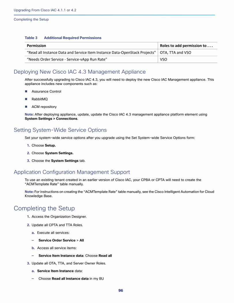
Upgrading From Cisco IAC 4.1.1 or 4.2
Completing the Setup
Deploying New Cisco IAC 4.3 Management ApplianceAfter successfully upgrading to Cisco IAC 4.3, you will need to deploy the new Cisco IAC Management appliance. This appliance includes new components such as:
Assurance Control
RabbitMQ
ACM repository
Note: After deploying appliance, update, update the Cisco IAC 4.3 management appliance platform element using System Settings > Connections.
Setting System-Wide Service OptionsSet your system-wide service options after you upgrade using the Set System-wide Service Options form:
1. Choose Setup.
2. Choose System Settings.
3. Choose the System Settings tab.
Application Configuration Management Support To use an existing tenant created in an earlier version of Cisco IAC, your CPBA or CPTA will need to create the “ACMTemplate Rate” table manually.
Note: For instructions on creating the “ACMTemplate Rate” table manually, see the Cisco Intelligent Automation for Cloud Knowledge Base.
Completing the Setup1. Access the Organization Designer.
2. Update all CPTA and TTA Roles.
a. Execute all services:
— Service Order Service > All
b. Access all service items:
— Service Item Instance data: Choose Read all
3. Update all OTA, TTA, and Server Owner Roles.
a. Service Item Instance data:
— Choose Read all instance data in my BU
Table 3 Additional Required Permissions
Permission Roles to add permission to . . .
“Read all Instance Data and Service Item Instance Data‐OpenStack Projects” OTA, TTA and VSO
“Needs Order Service ‐ Service‐vApp Run Rate” VSO
96

Upgrading From Cisco IAC 4.1.1 or 4.2
Completing the Setup
b. Add:
— nsAPI access
— Requisition Access
— Requisition System Account
Note: For more information on Organizations, Templates, Users, and so on, see the Cisco Intelligent Automation for Cloud 4.3 Administrator Guide.
Refreshing the Browser CacheAfter the upgrade process has finished, be sure to notify all Cisco IAC users to refresh their browser cache. They will continue to see the old version of Cisco IAC until they do so.
97

Upgrading From Cisco IAC 4.1.1 or 4.2
Completing the Setup
98
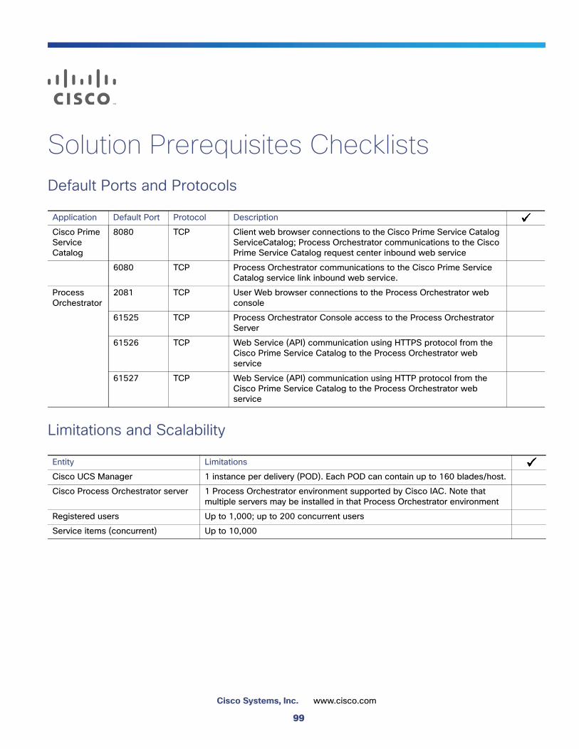
Solution Prerequisites ChecklistsDefault Ports and Protocols
Limitations and Scalability
Application Default Port Protocol Description
Cisco Prime Service Catalog
8080 TCP Client web browser connections to the Cisco Prime Service Catalog ServiceCatalog; Process Orchestrator communications to the Cisco Prime Service Catalog request center inbound web service
6080 TCP Process Orchestrator communications to the Cisco Prime Service Catalog service link inbound web service.
Process Orchestrator
2081 TCP User Web browser connections to the Process Orchestrator web console
61525 TCP Process Orchestrator Console access to the Process Orchestrator Server
61526 TCP Web Service (API) communication using HTTPS protocol from the Cisco Prime Service Catalog to the Process Orchestrator web service
61527 TCP Web Service (API) communication using HTTP protocol from the Cisco Prime Service Catalog to the Process Orchestrator web service
Entity Limitations
Cisco UCS Manager 1 instance per delivery (POD). Each POD can contain up to 160 blades/host.
Cisco Process Orchestrator server 1 Process Orchestrator environment supported by Cisco IAC. Note that multiple servers may be installed in that Process Orchestrator environment
Registered users Up to 1,000; up to 200 concurrent users
Service items (concurrent) Up to 10,000
99
Cisco Systems, Inc. www.cisco.com
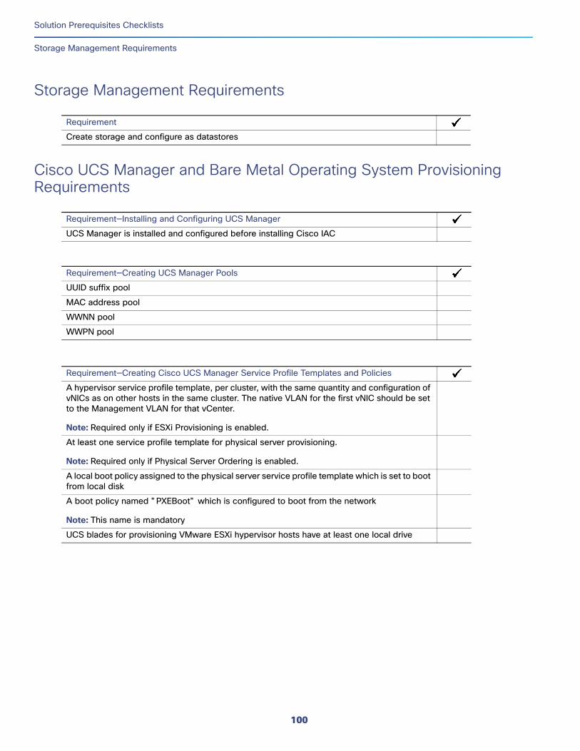
Solution Prerequisites Checklists
Storage Management Requirements
Storage Management Requirements
Cisco UCS Manager and Bare Metal Operating System Provisioning Requirements
Requirement
Create storage and configure as datastores
Requirement—Installing and Configuring UCS Manager
UCS Manager is installed and configured before installing Cisco IAC
Requirement—Creating UCS Manager Pools
UUID suffix pool
MAC address pool
WWNN pool
WWPN pool
Requirement—Creating Cisco UCS Manager Service Profile Templates and Policies
A hypervisor service profile template, per cluster, with the same quantity and configuration of vNICs as on other hosts in the same cluster. The native VLAN for the first vNIC should be set to the Management VLAN for that vCenter.
Note: Required only if ESXi Provisioning is enabled.
At least one service profile template for physical server provisioning.
Note: Required only if Physical Server Ordering is enabled.
A local boot policy assigned to the physical server service profile template which is set to boot from local disk
A boot policy named "PXEBoot" which is configured to boot from the network
Note: This name is mandatory
UCS blades for provisioning VMware ESXi hypervisor hosts have at least one local drive
100
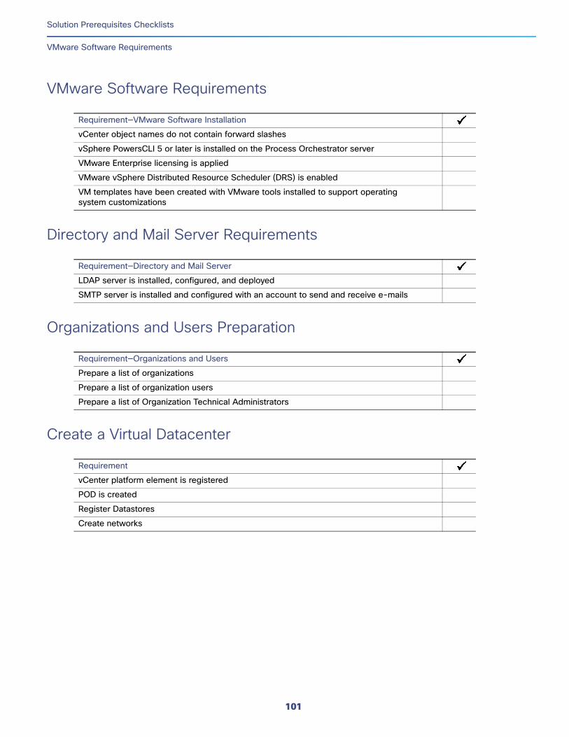
Solution Prerequisites Checklists
VMware Software Requirements
VMware Software Requirements
Directory and Mail Server Requirements
Organizations and Users Preparation
Create a Virtual Datacenter
Requirement—VMware Software Installation
vCenter object names do not contain forward slashes
vSphere PowersCLI 5 or later is installed on the Process Orchestrator server
VMware Enterprise licensing is applied
VMware vSphere Distributed Resource Scheduler (DRS) is enabled
VM templates have been created with VMware tools installed to support operating system customizations
Requirement—Directory and Mail Server
LDAP server is installed, configured, and deployed
SMTP server is installed and configured with an account to send and receive e-mails
Requirement—Organizations and Users
Prepare a list of organizations
Prepare a list of organization users
Prepare a list of Organization Technical Administrators
Requirement
vCenter platform element is registered
POD is created
Register Datastores
Create networks
101
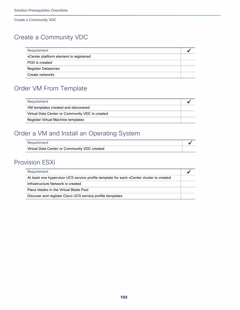
Solution Prerequisites Checklists
Create a Community VDC
Create a Community VDC
Order VM From Template
Order a VM and Install an Operating SystemRequirement
Provision ESXiRequirement
Requirement
vCenter platform element is registered
POD is created
Register Datastores
Create networks
Requirement
VM templates created and discovered
Virtual Data Center or Community VDC is created
Register Virtual Machine templates
Virtual Data Center or Community VDC created
At least one hypervisor UCS service profile template for each vCenter cluster is created
Infrastructure Network is created
Place blades in the Virtual Blade Pool
Discover and register Cisco UCS service profile templates
102
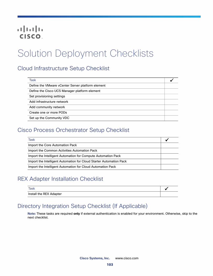
Solution Deployment ChecklistsCloud Infrastructure Setup Checklist
Cisco Process Orchestrator Setup Checklist
REX Adapter Installation Checklist
Directory Integration Setup Checklist (If Applicable) Note: These tasks are required only if external authentication is enabled for your environment. Otherwise, skip to the next checklist.
Task
Define the VMware vCenter Server platform element
Define the Cisco UCS Manager platform element
Set provisioning settings
Add infrastructure network
Add community network
Create one or more PODs
Set up the Community VDC
Task
Import the Core Automation Pack
Import the Common Activities Automation Pack
Import the Intelligent Automation for Compute Automation Pack
Import the Intelligent Automation for Cloud Starter Automation Pack
Import the Intelligent Automation for Cloud Automation Pack
Task
Install the REX Adapter
103
Cisco Systems, Inc. www.cisco.com
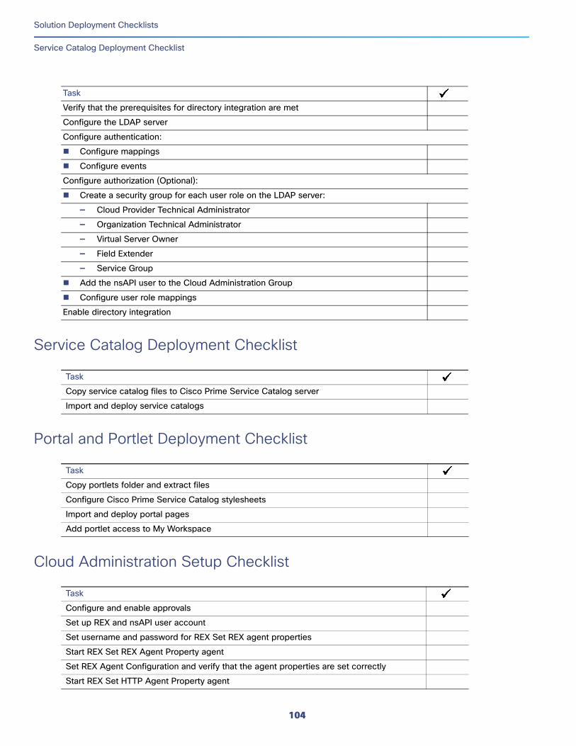
Solution Deployment Checklists
Service Catalog Deployment Checklist
Service Catalog Deployment Checklist
Portal and Portlet Deployment Checklist
Cloud Administration Setup Checklist
Task
Verify that the prerequisites for directory integration are met
Configure the LDAP server
Configure authentication:
Configure mappings
Configure events
Configure authorization (Optional):
Create a security group for each user role on the LDAP server:
— Cloud Provider Technical Administrator
— Organization Technical Administrator
— Virtual Server Owner
— Field Extender
— Service Group
Add the nsAPI user to the Cloud Administration Group
Configure user role mappings
Enable directory integration
Task
Copy service catalog files to Cisco Prime Service Catalog server
Import and deploy service catalogs
Task
Copy portlets folder and extract files
Configure Cisco Prime Service Catalog stylesheets
Import and deploy portal pages
Add portlet access to My Workspace
Task
Configure and enable approvals
Set up REX and nsAPI user account
Set username and password for REX Set REX agent properties
Start REX Set REX Agent Property agent
Set REX Agent Configuration and verify that the agent properties are set correctly
Start REX Set HTTP Agent Property agent
104
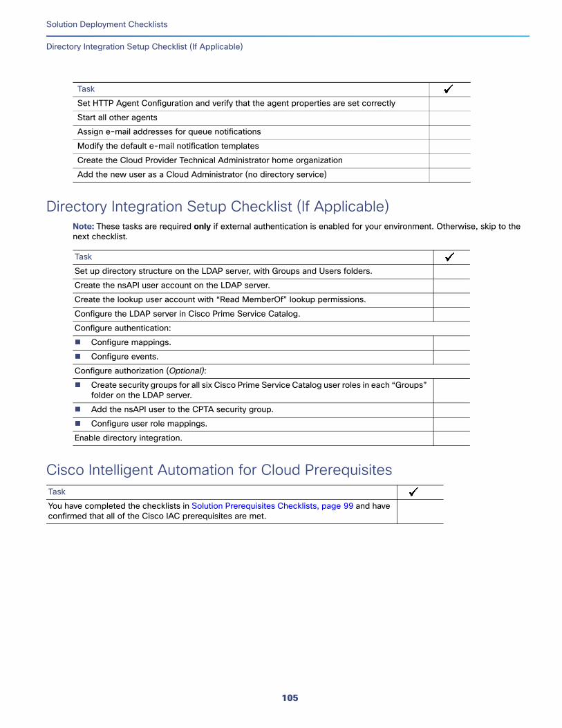
Solution Deployment Checklists
Directory Integration Setup Checklist (If Applicable)
Directory Integration Setup Checklist (If Applicable) Note: These tasks are required only if external authentication is enabled for your environment. Otherwise, skip to the next checklist.
Task
Cisco Intelligent Automation for Cloud PrerequisitesTask
Set HTTP Agent Configuration and verify that the agent properties are set correctly
Start all other agents
Assign e-mail addresses for queue notifications
Modify the default e-mail notification templates
Create the Cloud Provider Technical Administrator home organization
Add the new user as a Cloud Administrator (no directory service)
Task
Set up directory structure on the LDAP server, with Groups and Users folders.
Create the nsAPI user account on the LDAP server.
Create the lookup user account with “Read MemberOf” lookup permissions.
Configure the LDAP server in Cisco Prime Service Catalog.
Configure authentication:
Configure mappings.
Configure events.
Configure authorization (Optional):
Create security groups for all six Cisco Prime Service Catalog user roles in each “Groups” folder on the LDAP server.
Add the nsAPI user to the CPTA security group.
Configure user role mappings.
Enable directory integration.
You have completed the checklists in Solution Prerequisites Checklists, page 99 and have confirmed that all of the Cisco IAC prerequisites are met.
105
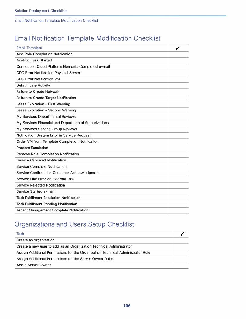
Solution Deployment Checklists
Email Notification Template Modification Checklist
Email Notification Template Modification ChecklistEmail Template
Organizations and Users Setup ChecklistTask
Add Role Completion Notification
Ad-Hoc Task Started
Connection Cloud Platform Elements Completed e-mail
CPO Error Notification Physical Server
CPO Error Notification VM
Default Late Activity
Failure to Create Network
Failure to Create Target Notification
Lease Expiration - First Warning
Lease Expiration - Second Warning
My Services Departmental Reviews
My Services Financial and Departmental Authorizations
My Services Service Group Reviews
Notification System Error in Service Request
Order VM from Template Completion Notification
Process Escalation
Remove Role Completion Notification
Service Canceled Notification
Service Complete Notification
Service Confirmation Customer Acknowledgment
Service Link Error on External Task
Service Rejected Notification
Service Started e-mail
Task Fulfillment Escalation Notification
Task Fulfillment Pending Notification
Tenant Management Complete Notification
Create an organization
Create a new user to add as an Organization Technical Administrator
Assign Additional Permissions for the Organization Technical Administrator Role
Assign Additional Permissions for the Server Owner Roles
Add a Server Owner
106
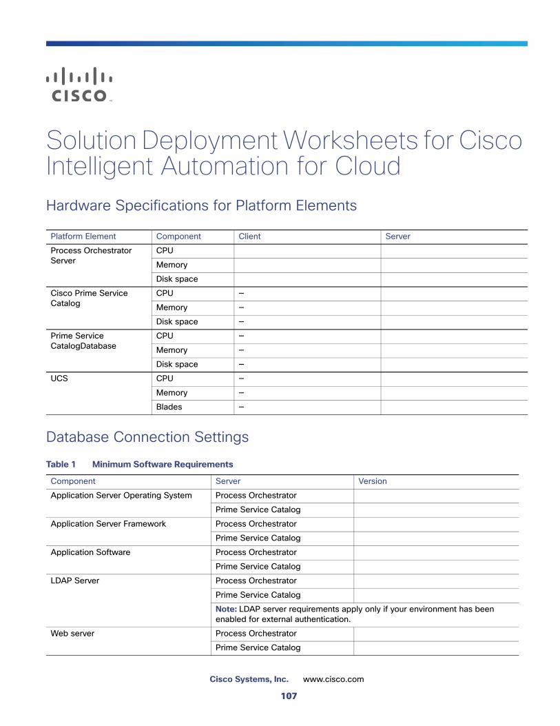
Solution Deployment Worksheets for Cisco Intelligent Automation for CloudHardware Specifications for Platform Elements
Database Connection Settings
Platform Element Component Client Server
Process Orchestrator Server
CPU
Memory
Disk space
Cisco Prime Service Catalog
CPU —
Memory —
Disk space —
Prime Service CatalogDatabase
CPU —
Memory —
Disk space —
UCS CPU —
Memory —
Blades —
Table 1 Minimum Software Requirements
Component Server Version
Application Server Operating System Process Orchestrator
Prime Service Catalog
Application Server Framework Process Orchestrator
Prime Service Catalog
Application Software Process Orchestrator
Prime Service Catalog
LDAP Server Process Orchestrator
Prime Service Catalog
Note: LDAP server requirements apply only if your environment has been enabled for external authentication.
Web server Process Orchestrator
Prime Service Catalog
107
Cisco Systems, Inc. www.cisco.com
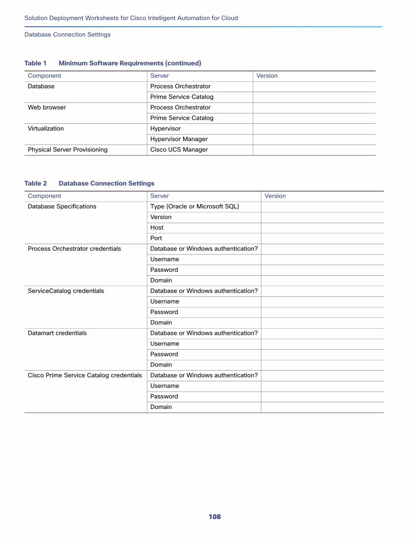
Solution Deployment Worksheets for Cisco Intelligent Automation for Cloud
Database Connection Settings
Database Process Orchestrator
Prime Service Catalog
Web browser Process Orchestrator
Prime Service Catalog
Virtualization Hypervisor
Hypervisor Manager
Physical Server Provisioning Cisco UCS Manager
Table 1 Minimum Software Requirements (continued)
Component Server Version
Table 2 Database Connection Settings
Component Server Version
Database Specifications Type (Oracle or Microsoft SQL)
Version
Host
Port
Process Orchestrator credentials Database or Windows authentication?
Username
Password
Domain
ServiceCatalog credentials Database or Windows authentication?
Username
Password
Domain
Datamart credentials Database or Windows authentication?
Username
Password
Domain
Cisco Prime Service Catalog credentials Database or Windows authentication?
Username
Password
Domain
108
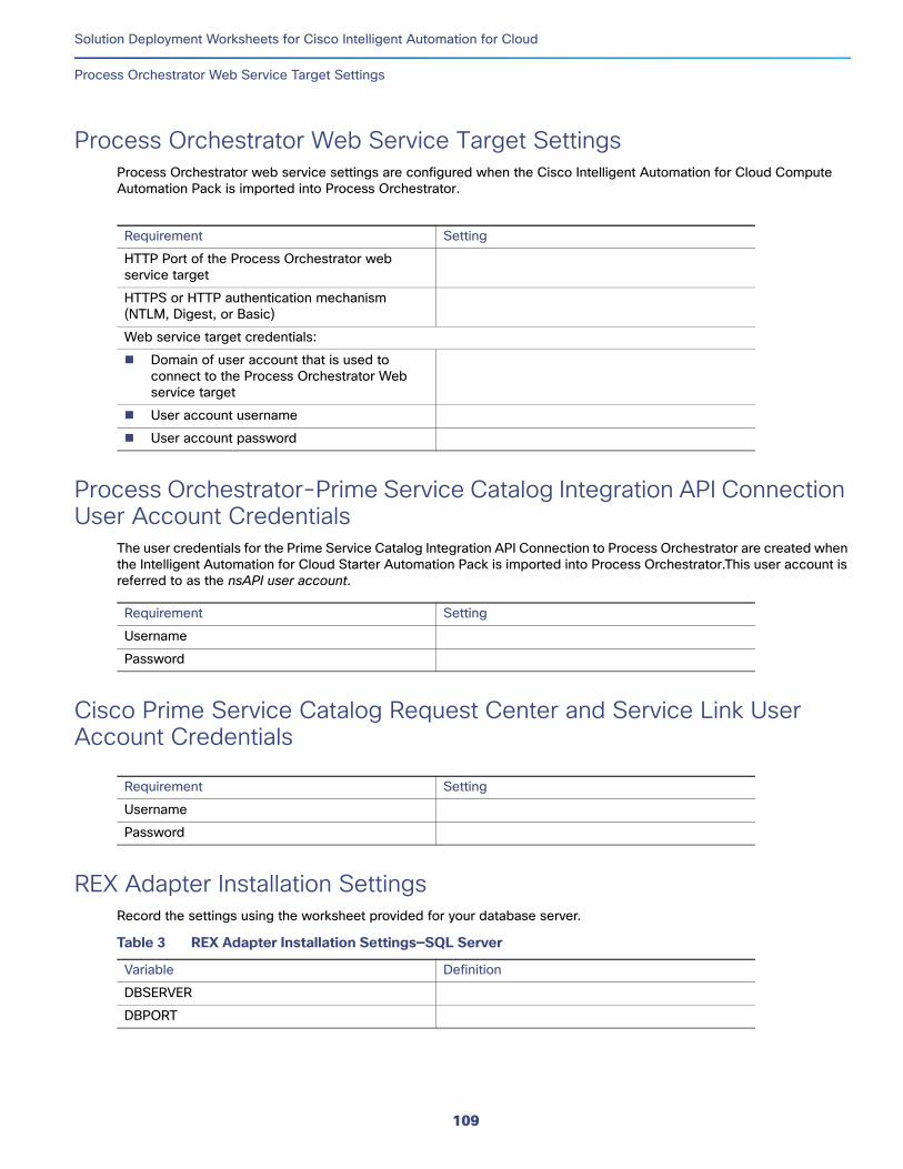
Solution Deployment Worksheets for Cisco Intelligent Automation for Cloud
Process Orchestrator Web Service Target Settings
Process Orchestrator Web Service Target SettingsProcess Orchestrator web service settings are configured when the Cisco Intelligent Automation for Cloud Compute Automation Pack is imported into Process Orchestrator.
Process Orchestrator-Prime Service Catalog Integration API Connection User Account Credentials
The user credentials for the Prime Service Catalog Integration API Connection to Process Orchestrator are created when the Intelligent Automation for Cloud Starter Automation Pack is imported into Process Orchestrator.This user account is referred to as the nsAPI user account.
Cisco Prime Service Catalog Request Center and Service Link User Account Credentials
REX Adapter Installation SettingsRecord the settings using the worksheet provided for your database server.
Requirement Setting
HTTP Port of the Process Orchestrator web service target
HTTPS or HTTP authentication mechanism (NTLM, Digest, or Basic)
Web service target credentials:
Domain of user account that is used to connect to the Process Orchestrator Web service target
User account username
User account password
Requirement Setting
Username
Password
Requirement Setting
Username
Password
Table 3 REX Adapter Installation Settings—SQL Server
Variable Definition
DBSERVER
DBPORT
109
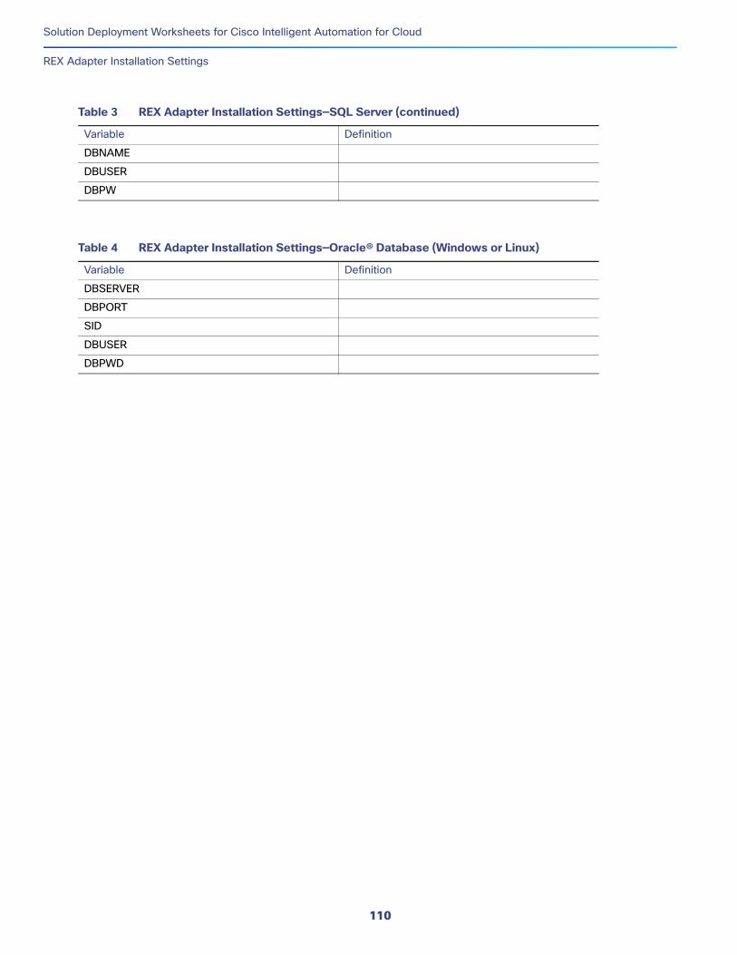
Solution Deployment Worksheets for Cisco Intelligent Automation for Cloud
REX Adapter Installation Settings
DBNAME
DBUSER
DBPW
Table 4 REX Adapter Installation Settings—Oracle® Database (Windows or Linux)
Variable Definition
DBSERVER
DBPORT
SID
DBUSER
DBPWD
Table 3 REX Adapter Installation Settings—SQL Server (continued)
Variable Definition
110
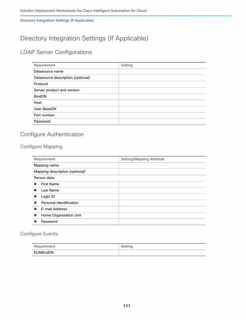
Solution Deployment Worksheets for Cisco Intelligent Automation for Cloud
Directory Integration Settings (If Applicable)
Directory Integration Settings (If Applicable)
LDAP Server Configurations
Configure Authentication
Configure Mapping
Configure Events
Requirement Setting
Datasource name
Datasource description (optional)
Protocol
Server product and version
BindDN
Host
User BaseDN
Port number
Password
Requirement Setting/Mapping Attribute
Mapping name
Mapping description (optional)
Person data:
First Name
Last Name
Login ID
Personal Identification
E-mail Address
Home Organization Unit
Password
Requirement Setting
EUABindDN
111
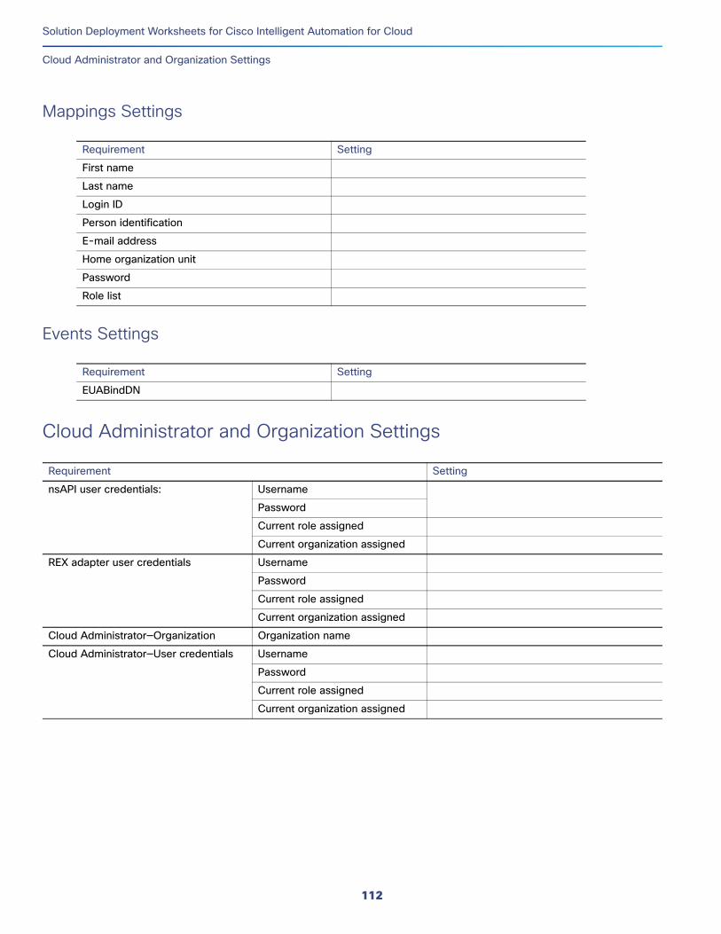
Solution Deployment Worksheets for Cisco Intelligent Automation for Cloud
Cloud Administrator and Organization Settings
Mappings Settings
Events Settings
Cloud Administrator and Organization Settings
Requirement Setting
First name
Last name
Login ID
Person identification
E-mail address
Home organization unit
Password
Role list
Requirement Setting
EUABindDN
Requirement Setting
nsAPI user credentials: Username
Password
Current role assigned
Current organization assigned
REX adapter user credentials Username
Password
Current role assigned
Current organization assigned
Cloud Administrator—Organization Organization name
Cloud Administrator—User credentials Username
Password
Current role assigned
Current organization assigned
112
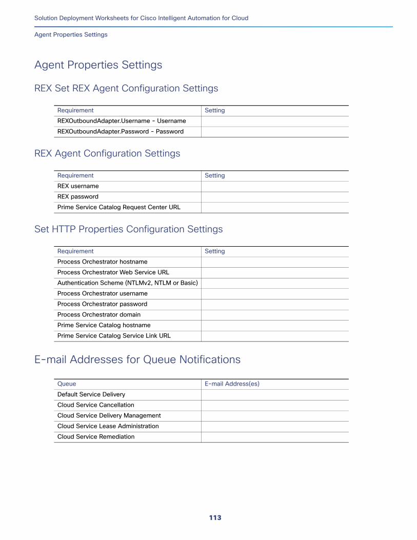
Solution Deployment Worksheets for Cisco Intelligent Automation for Cloud
Agent Properties Settings
Agent Properties Settings
REX Set REX Agent Configuration Settings
REX Agent Configuration Settings
Set HTTP Properties Configuration Settings
E-mail Addresses for Queue Notifications
Requirement Setting
REXOutboundAdapter.Username - Username
REXOutboundAdapter.Password - Password
Requirement Setting
REX username
REX password
Prime Service Catalog Request Center URL
Requirement Setting
Process Orchestrator hostname
Process Orchestrator Web Service URL
Authentication Scheme (NTLMv2, NTLM or Basic)
Process Orchestrator username
Process Orchestrator password
Process Orchestrator domain
Prime Service Catalog hostname
Prime Service Catalog Service Link URL
Queue E-mail Address(es)
Default Service Delivery
Cloud Service Cancellation
Cloud Service Delivery Management
Cloud Service Lease Administration
Cloud Service Remediation
113
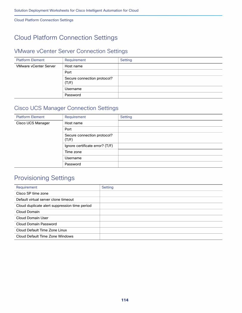
Solution Deployment Worksheets for Cisco Intelligent Automation for Cloud
Cloud Platform Connection Settings
Cloud Platform Connection Settings
VMware vCenter Server Connection SettingsPlatform Element Requirement Setting
Cisco UCS Manager Connection SettingsPlatform Element Requirement Setting
Provisioning SettingsRequirement Setting
VMware vCenter Server Host name
Port
Secure connection protocol? (T/F)
Username
Password
Cisco UCS Manager Host name
Port
Secure connection protocol? (T/F)
Ignore certificate error? (T/F)
Time zone
Username
Password
Cisco SP time zone
Default virtual server clone timeout
Cloud duplicate alert suppression time period
Cloud Domain
Cloud Domain User
Cloud Domain Password
Cloud Default Time Zone Linux
Cloud Default Time Zone Windows
114
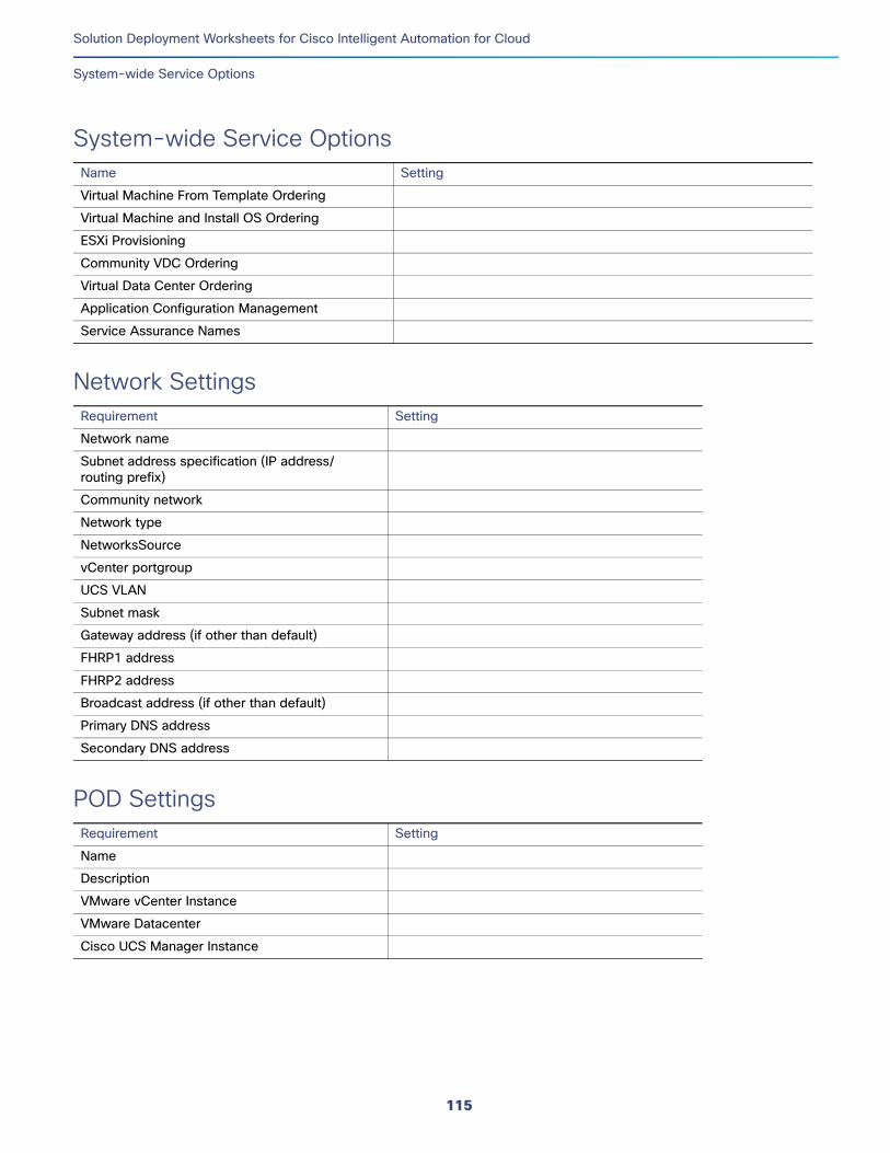
Solution Deployment Worksheets for Cisco Intelligent Automation for Cloud
System-wide Service Options
System-wide Service OptionsName Setting
Network SettingsRequirement Setting
POD SettingsRequirement Setting
Virtual Machine From Template Ordering
Virtual Machine and Install OS Ordering
ESXi Provisioning
Community VDC Ordering
Virtual Data Center Ordering
Application Configuration Management
Service Assurance Names
Network name
Subnet address specification (IP address/ routing prefix)
Community network
Network type
NetworksSource
vCenter portgroup
UCS VLAN
Subnet mask
Gateway address (if other than default)
FHRP1 address
FHRP2 address
Broadcast address (if other than default)
Primary DNS address
Secondary DNS address
Name
Description
VMware vCenter Instance
VMware Datacenter
Cisco UCS Manager Instance
115
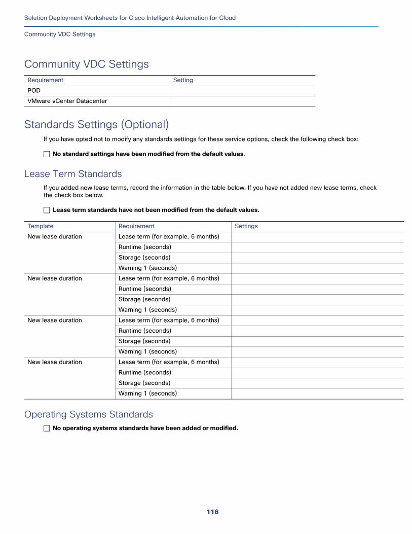
Solution Deployment Worksheets for Cisco Intelligent Automation for Cloud
Community VDC Settings
Community VDC SettingsRequirement Setting
Standards Settings (Optional)If you have opted not to modify any standards settings for these service options, check the following check box:
No standard settings have been modified from the default values.
Lease Term StandardsIf you added new lease terms, record the information in the table below. If you have not added new lease terms, check the check box below.
Lease term standards have not been modified from the default values.
Operating Systems StandardsNo operating systems standards have been added or modified.
POD
VMware vCenter Datacenter
Template Requirement Settings
New lease duration Lease term (for example, 6 months)
Runtime (seconds)
Storage (seconds)
Warning 1 (seconds)
New lease duration Lease term (for example, 6 months)
Runtime (seconds)
Storage (seconds)
Warning 1 (seconds)
New lease duration Lease term (for example, 6 months)
Runtime (seconds)
Storage (seconds)
Warning 1 (seconds)
New lease duration Lease term (for example, 6 months)
Runtime (seconds)
Storage (seconds)
Warning 1 (seconds)
116
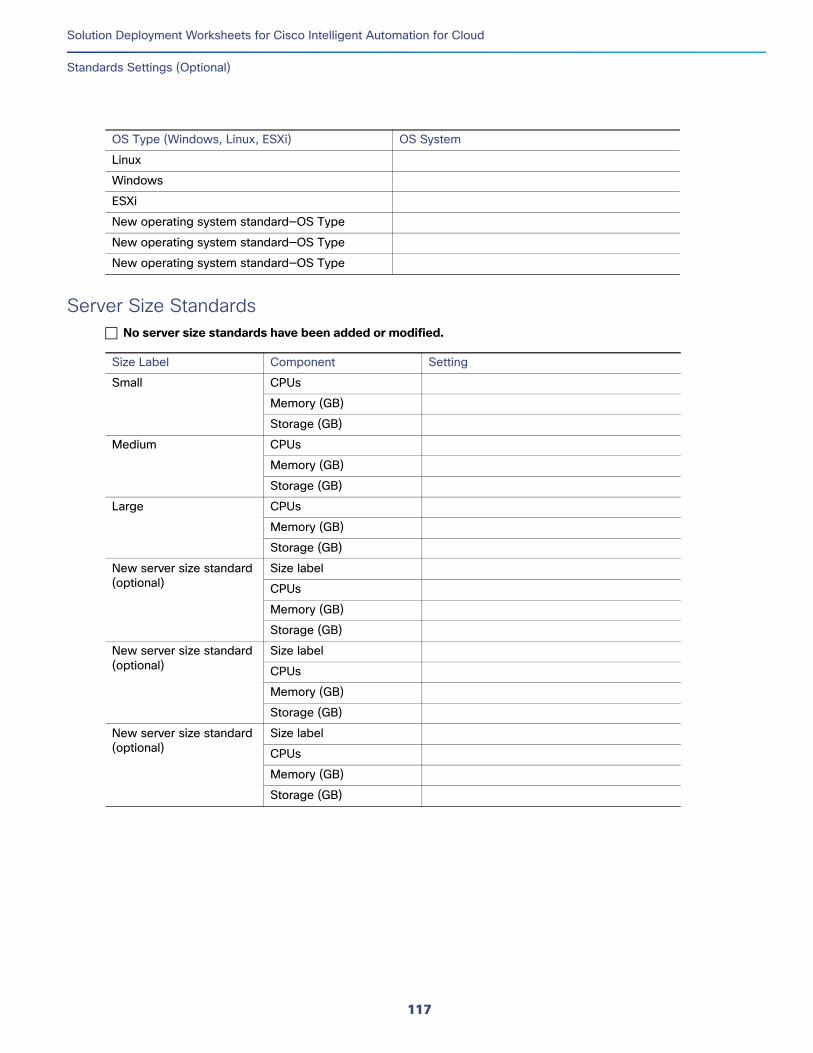
Solution Deployment Worksheets for Cisco Intelligent Automation for Cloud
Standards Settings (Optional)
Server Size StandardsNo server size standards have been added or modified.
OS Type (Windows, Linux, ESXi) OS System
Linux
Windows
ESXi
New operating system standard—OS Type
New operating system standard—OS Type
New operating system standard—OS Type
Size Label Component Setting
Small CPUs
Memory (GB)
Storage (GB)
Medium CPUs
Memory (GB)
Storage (GB)
Large CPUs
Memory (GB)
Storage (GB)
New server size standard (optional)
Size label
CPUs
Memory (GB)
Storage (GB)
New server size standard (optional)
Size label
CPUs
Memory (GB)
Storage (GB)
New server size standard (optional)
Size label
CPUs
Memory (GB)
Storage (GB)
117
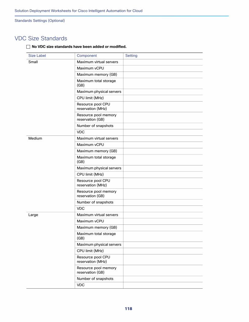
Solution Deployment Worksheets for Cisco Intelligent Automation for Cloud
Standards Settings (Optional)
VDC Size StandardsNo VDC size standards have been added or modified.
Size Label Component Setting
Small Maximum virtual servers
Maximum vCPU
Maximum memory (GB)
Maximum total storage (GB)
Maximum physical servers
CPU limit (MHz)
Resource pool CPU reservation (MHz)
Resource pool memory reservation (GB)
Number of snapshots
VDC
Medium Maximum virtual servers
Maximum vCPU
Maximum memory (GB)
Maximum total storage (GB)
Maximum physical servers
CPU limit (MHz)
Resource pool CPU reservation (MHz)
Resource pool memory reservation (GB)
Number of snapshots
VDC
Large Maximum virtual servers
Maximum vCPU
Maximum memory (GB)
Maximum total storage (GB)
Maximum physical servers
CPU limit (MHz)
Resource pool CPU reservation (MHz)
Resource pool memory reservation (GB)
Number of snapshots
VDC
118
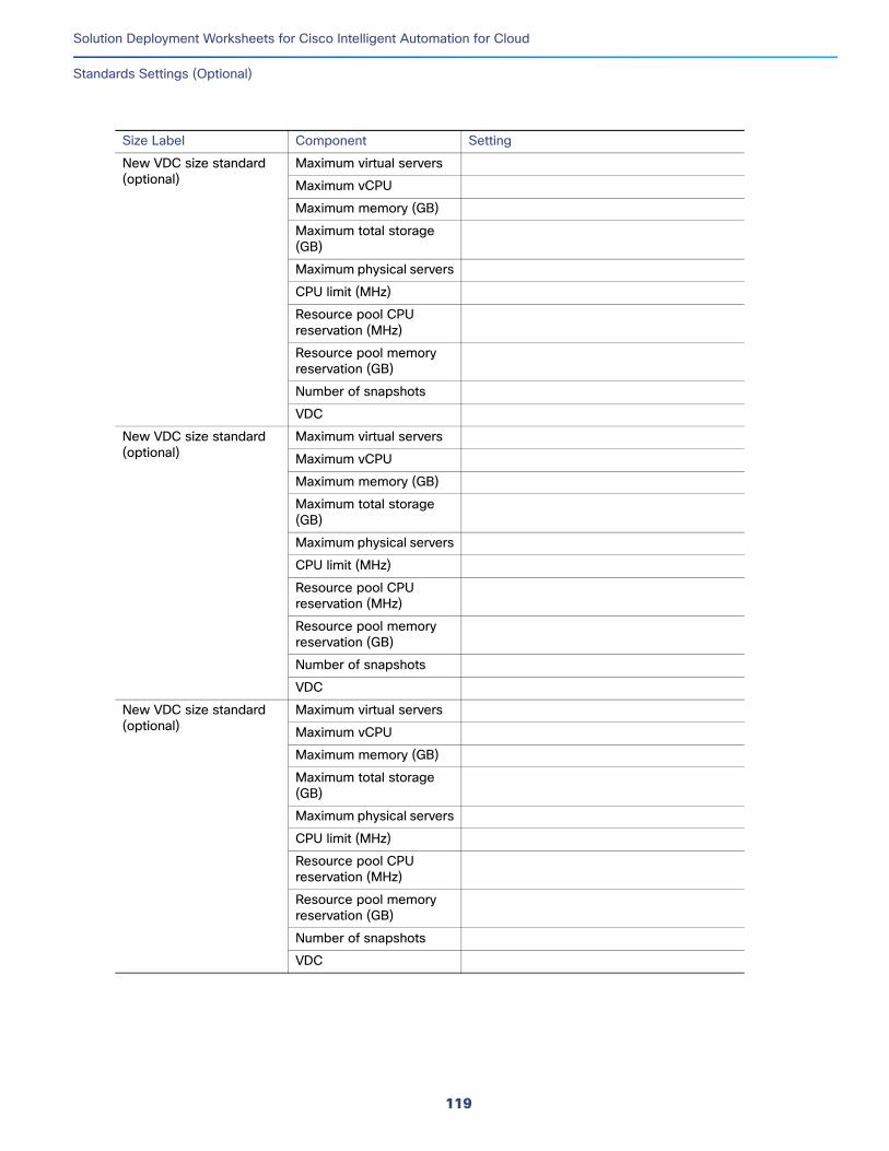
Solution Deployment Worksheets for Cisco Intelligent Automation for Cloud
Standards Settings (Optional)
New VDC size standard (optional)
Maximum virtual servers
Maximum vCPU
Maximum memory (GB)
Maximum total storage (GB)
Maximum physical servers
CPU limit (MHz)
Resource pool CPU reservation (MHz)
Resource pool memory reservation (GB)
Number of snapshots
VDC
New VDC size standard (optional)
Maximum virtual servers
Maximum vCPU
Maximum memory (GB)
Maximum total storage (GB)
Maximum physical servers
CPU limit (MHz)
Resource pool CPU reservation (MHz)
Resource pool memory reservation (GB)
Number of snapshots
VDC
New VDC size standard (optional)
Maximum virtual servers
Maximum vCPU
Maximum memory (GB)
Maximum total storage (GB)
Maximum physical servers
CPU limit (MHz)
Resource pool CPU reservation (MHz)
Resource pool memory reservation (GB)
Number of snapshots
VDC
Size Label Component Setting
119

Solution Deployment Worksheets for Cisco Intelligent Automation for Cloud
Standards Settings (Optional)
120
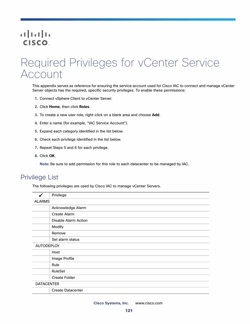
Required Privileges for vCenter Service Account
This appendix serves as reference for ensuring the service account used for Cisco IAC to connect and manage vCenter Server objects has the required, specific security privileges. To enable these permissions:
1. Connect vSphere Client to vCenter Server.
2. Click Home, then click Roles.
3. To create a new user role, right-click on a blank area and choose Add.
4. Enter a name (for example, “IAC Service Account”).
5. Expand each category identified in the list below.
6. Check each privilege identified in the list below.
7. Repeat Steps 5 and 6 for each privilege.
8. Click OK.
Note: Be sure to add permission for this role to each datacenter to be managed by IAC.
Privilege ListThe following privileges are used by Cisco IAC to manage vCenter Servers.
Privilege
ALARMS
Acknowledge Alarm
Create Alarm
Disable Alarm Action
Modify
Remove
Set alarm status
AUTODEPLOY
Host
Image Profile
Rule
RuleSet
Create Folder
DATACENTER
Create Datacenter
121
Cisco Systems, Inc. www.cisco.com
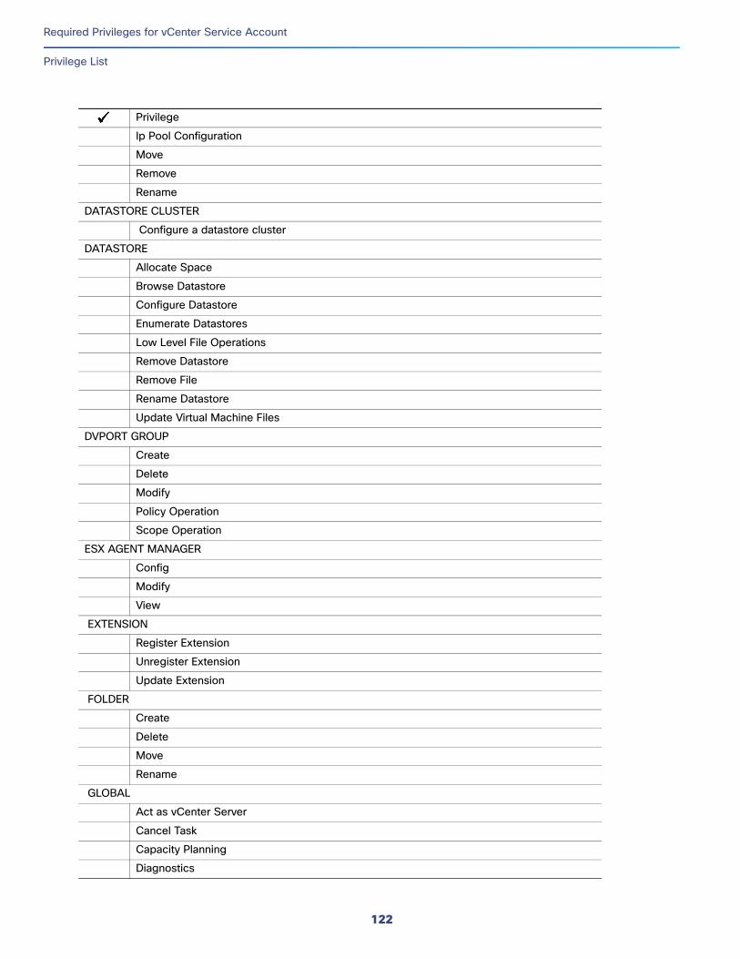
Required Privileges for vCenter Service Account
Privilege List
Ip Pool Configuration
Move
Remove
Rename
DATASTORE CLUSTER
Configure a datastore cluster
DATASTORE
Allocate Space
Browse Datastore
Configure Datastore
Enumerate Datastores
Low Level File Operations
Remove Datastore
Remove File
Rename Datastore
Update Virtual Machine Files
DVPORT GROUP
Create
Delete
Modify
Policy Operation
Scope Operation
ESX AGENT MANAGER
Config
Modify
View
EXTENSION
Register Extension
Unregister Extension
Update Extension
FOLDER
Create
Delete
Move
Rename
GLOBAL
Act as vCenter Server
Cancel Task
Capacity Planning
Diagnostics
Privilege
122
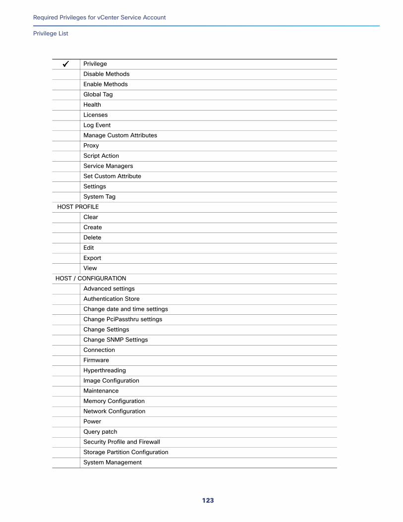
Required Privileges for vCenter Service Account
Privilege List
Disable Methods
Enable Methods
Global Tag
Health
Licenses
Log Event
Manage Custom Attributes
Proxy
Script Action
Service Managers
Set Custom Attribute
Settings
System Tag
HOST PROFILE
Clear
Create
Delete
Edit
Export
View
HOST / CONFIGURATION
Advanced settings
Authentication Store
Change date and time settings
Change PciPassthru settings
Change Settings
Change SNMP Settings
Connection
Firmware
Hyperthreading
Image Configuration
Maintenance
Memory Configuration
Network Configuration
Power
Query patch
Security Profile and Firewall
Storage Partition Configuration
System Management
Privilege
123
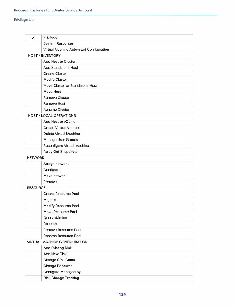
Required Privileges for vCenter Service Account
Privilege List
System Resources
Virtual Machine Auto-start Configuration
HOST / INVENTORY
Add Host to Cluster
Add Standalone Host
Create Cluster
Modify Cluster
Move Cluster or Standalone Host
Move Host
Remove Cluster
Remove Host
Rename Cluster
HOST / LOCAL OPERATIONS
Add Host to vCenter
Create Virtual Machine
Delete Virtual Machine
Manage User Groups
Reconfigure Virtual Machine
Relay Out Snapshots
NETWORK
Assign network
Configure
Move network
Remove
RESOURCE
Create Resource Pool
Migrate
Modify Resource Pool
Move Resource Pool
Query vMotion
Relocate
Remove Resource Pool
Rename Resource Pool
VIRTUAL MACHINE CONFIGURATION
Add Existing Disk
Add New Disk
Change CPU Count
Change Resource
Configure Managed By
Disk Change Tracking
Privilege
124
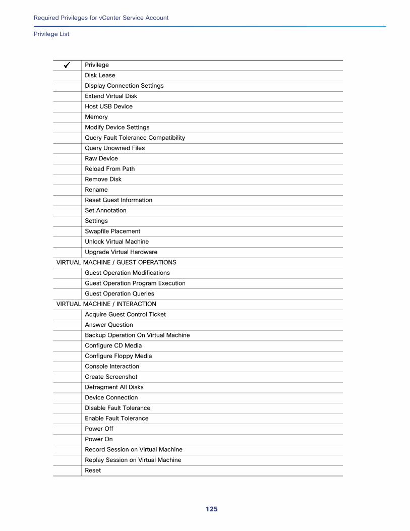
Required Privileges for vCenter Service Account
Privilege List
Disk Lease
Display Connection Settings
Extend Virtual Disk
Host USB Device
Memory
Modify Device Settings
Query Fault Tolerance Compatibility
Query Unowned Files
Raw Device
Reload From Path
Remove Disk
Rename
Reset Guest Information
Set Annotation
Settings
Swapfile Placement
Unlock Virtual Machine
Upgrade Virtual Hardware
VIRTUAL MACHINE / GUEST OPERATIONS
Guest Operation Modifications
Guest Operation Program Execution
Guest Operation Queries
VIRTUAL MACHINE / INTERACTION
Acquire Guest Control Ticket
Answer Question
Backup Operation On Virtual Machine
Configure CD Media
Configure Floppy Media
Console Interaction
Create Screenshot
Defragment All Disks
Device Connection
Disable Fault Tolerance
Enable Fault Tolerance
Power Off
Power On
Record Session on Virtual Machine
Replay Session on Virtual Machine
Reset
Privilege
125
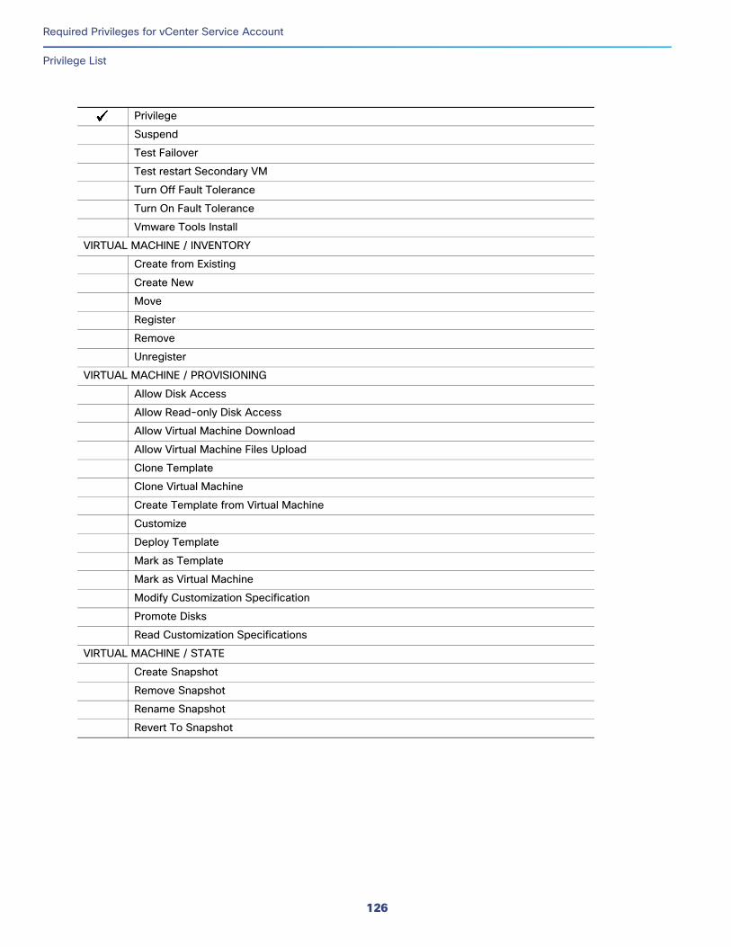
Required Privileges for vCenter Service Account
Privilege List
Suspend
Test Failover
Test restart Secondary VM
Turn Off Fault Tolerance
Turn On Fault Tolerance
Vmware Tools Install
VIRTUAL MACHINE / INVENTORY
Create from Existing
Create New
Move
Register
Remove
Unregister
VIRTUAL MACHINE / PROVISIONING
Allow Disk Access
Allow Read-only Disk Access
Allow Virtual Machine Download
Allow Virtual Machine Files Upload
Clone Template
Clone Virtual Machine
Create Template from Virtual Machine
Customize
Deploy Template
Mark as Template
Mark as Virtual Machine
Modify Customization Specification
Promote Disks
Read Customization Specifications
VIRTUAL MACHINE / STATE
Create Snapshot
Remove Snapshot
Rename Snapshot
Revert To Snapshot
Privilege
126