cisco ggsn
TRANSCRIPT

GGSN Release 8.0 Configuration GuideCisco IOS Release 12.4(15)XQ3 Cisco Service and Application Module for IP, Cisco 7600 Series Internet Router Platform Last updated September 8, 2009
Americas HeadquartersCisco Systems, Inc.170 West Tasman DriveSan Jose, CA 95134-1706 USAhttp://www.cisco.comTel: 408 526-4000
800 553-NETS (6387)Fax: 408 527-0883

C O N T E N T S
C H A P T E R 1 Overview of GPRS and UMTS 1
Overview 1
Benefits 4
New Features in this Release 5GGSN-Initiated Update PDP Context Requests 5RADIUS Change of Authorization Message 5PPP-Regeneration Scalability 6AAA Enhancements 6Anonymous User Access for PPP-Regeneration 6Downloadable Pool Name Support 7Direct Tunnel Support 7Configuring a Charging Source Interface 8Suppressing Echo Requests per SGSN 8iSCSI Transport Protocol Support 8MIB Enhancements 9
Features from Previous Releases 9
C H A P T E R 2 Planning to Configure the GGSN 1
Prerequisites 1Before You Begin 1Platform Prerequisites 2
Required Hardware and Software 2Required Base Configuration 2
Restrictions 9
Additional References 10
Related Documents 10
Standards 11
MIBS 13
RFCs 13
Technical Assistance 13
C H A P T E R 3 Configuring GTP Services on the GGSN 1
GTP Overview 1
3Cisco GGSN Release 8.0 Configuration Guide, Cisco IOS Release 12.4(15)XQ3

Contents
Configuring GGSN Services 2GGSN Services Configuration Task List 2Enabling GGSN Services 2Creating a Loopback Interface 3Creating a Virtual Template Interface for GGSN 3Enabling CEF Switching 4
Configuring Echo Timing on a GGSN 4Overview of the Echo Timing on the GGSN 5
Overview of the Default Echo Timer 5Overview of the Dynamic Echo Timer 7
Echo Timing Configuration Task List 10
Customizing the Default Echo Timer 10
Configuring the Dynamic Echo Timer 11
Disabling the Echo Timer 12
Verifying the Echo Timing Configuration 12
Verifying Echo Timing Parameters 12
Verifying the Dynamic Echo Timer by GTP Path 13
Customizing the GGSN Configuration 14
Configuring GTP Signaling Options 15
Configuring Other GTP Signaling Options 15
Configuring the Maximum Number of PDP Contexts on the GGSN 16
Configuring the Maximum Number of PDP Contexts When Using DFP with Load Balancing 17
Controlling Sessions on the GGSN 17
Configuring Session Timers 18
Deleting Sessions on the GGSN 23
Configuring Flow Control for GTP Error Messages 24
Configuring the GGSN to Maintain a History for Deleted SGSN Paths 25
Suppressing Echo Requests per SGSN 25
Configuring Support for GGSN-Initiated Update PDP Context Requests 26
Using the Service-Mode Function 27
Configuring Global Maintenance Mode 28
Configuring APN Maintenance Mode 29
Configuring Charging Maintenance Mode 30
Monitoring and Maintaining GTP on the GGSN 32
Configuration Examples 33
GGSN Configuration Example 33
Dynamic Echo Timer Configuration Example 34
4Cisco GGSN Release 8.0 Configuration Guide, Cisco IOS Release 12.4(15)XQ3

Contents
C H A P T E R 4 Configuring IPv6 PDP Support on the GGSN 37
IPv6 PDPs on the GGSN Overview 37
Supported Features 40
Restrictions 40
Implementing IPv6 PDP Support on the GGSN 41
Enabling the Forwarding of IPv6 Traffic on the GGSN 41
Configuring an IPv6 Base Virtual Template Interface 42
Enabling IPv6 Support on the APN 44
Configuring a Local IPv6 Prefix Pool 46
Configuring an IPv6 Access Control List 47
Configuring Additional IPv6 Support Options on the GGSN 49
Monitoring and Maintaining IPv6 PDPs 49
Configuration Example 50
C H A P T E R 5 Configuring GGSN GTP Session Redundancy 1
GTP Session Redundancy Overview 1Prerequisites 2Limitations and Restrictions 3
Enabling GTP Session Redundancy 4Configuring the GTP Session Redundancy Inter-Device Infrastructure 4
Configuring HSRP 4Enabling Inter-Device Redundancy 6Configuring the Inter-Device Communication Transport 7
Configuring GTP-SR on the GGSN 9
Disabling GTP Session Redundancy 9
Configuring Charging-Related Synchronization Parameters 10
Monitoring and Maintaining GTP-SR 12
Upgrading GGSN Images in a GTP-SR Environment 12
Configuration Examples 12
Primary Supervisor Configuration Example 13
Primary GGSN Configuration Example 16
Secondary GGSN Configuration Example 17
C H A P T E R 6 Configuring Charging on the GGSN 1
Configuring an Interface to the Charging Gateway 1Verifying Interface Configuration to the Charging Gateway 2
Configuring the Default Charging Gateway 4Configuring the GGSN to Switchover to the Highest Priority Charging Gateway 4
5Cisco GGSN Release 8.0 Configuration Guide, Cisco IOS Release 12.4(15)XQ3

Contents
Changing the Default Charging Gateway 5
Configuring a Charging Source Interface 5
Configuring the GGSN Memory Threshold 6
Configuring the Transport Protocol for the Charging Gateway 7Configuring TCP as the Charging Gateway Path Protocol 7Configuring UDP as the Charging Gateway Path Protocol 7
Configuring the Charging Release 7
Configuring Charging for Roamers 8Configuring PLMN IP Address Ranges 9Enabling Charging for Roamers 10
Customizing the Charging Gateway 10
Disabling Charging Processing 13
Using Charging Profiles 14
Configuring a Charging Profile 14
Defining the Charging Characteristics and Triggers of the Charging Profile 16
Applying a Default Charging Profile to an APN 17
Applying a Global Default Charging Profile 18
Configuring How the GGSN Handles PDPs with Unmatched Charging Profiles 18
Configuring G-CDR Backup and Retrieval using iSCSI 18
iSCSI Overview 18
Configuring iSCSI G-CDR Backup and Storage on the GGSN 19
Configuring an iSCSI Target Interface Profile 21
Associating an iSCSI Target Interface Profile 21
Verifying the iSCSI Session 21
Monitoring and Maintaining iSCSI G-CDR Backup and Storage 22
Monitoring and Maintaining Charging on the GGSN 22
Configuration Examples 23
Global Charging Configuration 23
Charging Profile Configuration 24
C H A P T E R 7 Configuring Enhanced Service-Aware Billing 1
Service-Aware GGSN Overview 1Service-Aware GGSN Data Flows 3Prerequisites 4Limitations and Restrictions 5
Configuring a Service-Aware GGSN 5Enabling Service-Aware Billing Support 5Enabling Enhanced G-CDRs 6
6Cisco GGSN Release 8.0 Configuration Guide, Cisco IOS Release 12.4(15)XQ3

Contents
Configuring the Quota Server Interface 7Configuring a Cisco CSG2 Server Group 7Configuring the Quota Server Process on the GGSN 8Advertising the Next Hop Address For Downlink Traffic 10
Configuring the GGSN to use the Cisco CSG2 as an Authentication and Accounting Proxy 10
Monitoring and Maintaining 11
Configuring Diameter/DCCA Interface Support 12
Configuring the Diameter Base 13
Configuring the DCCA Client Process on the GGSN 18
Enabling Support for Vendor-Specific AVPs in DCCA Messages 22
Configuring the Enhanced Billing Parameters in Charging Profiles 22
Specifying a Default Rulebase ID 23
Specifying a DCCA Client Profile to Use for Online Billing 23
Suppressing CDRs for Prepaid Users 24
Configuring Trigger Conditions for Postpaid Users 24
GTP-Session Redundancy for Service-Aware PDPs Overview 26
Configuring OCS Address Selection Support 27
Configuration Example 28
C H A P T E R 8 Configuring Network Access to the GGSN 1
Configuring an Interface to the SGSN 1Verifying the Interface Configuration to the SGSN 2
Configuring a Route to the SGSN 4Configuring a Static Route to the SGSN 4Configuring OSPF 5Verifying the Route to the SGSN 5
Configuring Access Points on the GGSN 7Overview of Access Points 8
Description of Access Points in a GPRS/UMTS Network 8Access Point Implementation on the Cisco GGSN 9
Basic Access Point Configuration Task List 10
Configuring the GPRS Access Point List on the GGSN 10
Creating an Access Point and Specifying Its Type on the GGSN 10
Configuring Real Access Points on the GGSN 11
PDN Access Configuration Task List 12
VPN Access Using VRF Configuration Task Lists 13
Configuring Additional Real Access Point Options 20
Verifying the Real Access Point Configuration 26
Configuring Virtual Access Points on the GGSN 31
7Cisco GGSN Release 8.0 Configuration Guide, Cisco IOS Release 12.4(15)XQ3

Contents
Overview of the Virtual Access Point Feature 31
Virtual Access Point Configuration Task List 34
Verifying the Virtual Access Point Configuration 36
Configuring Access to External Support Servers 40
Blocking Access to the GGSN by Foreign Mobile Stations 40
Overview of Blocking Foreign Mobile Stations 40
Blocking Foreign Mobile Stations Configuration Task List 41
Configuring the MCC and MNC Values 41
Enabling Blocking of Foreign Mobile Stations on the GGSN 42
Verifying the Blocking of Foreign Mobile Stations Configuration 42
Controlling Access to the GGSN by MSs with Duplicate IP Addresses 43
Configuring Routing Behind the Mobile Station on an APN 44
Enabling Routing Behind the Mobile Station 44
Verifying the Routing Behind the Mobile Station Configuration 45
Configuring Proxy-CSCF Discovery Support on an APN 47
Creating P-CSCF Server Groups on the GGSN 47
Specifying a P-CSCF Server Groups on an APN 48
Verifying the P-CSCF Discovery Configuration 48
Monitoring and Maintaining Access Points on the GGSN 48
Configuration Examples 49
Static Route to SGSN Example 50
Access Point List Configuration Example 51
VRF Tunnel Configuration Example 52
Virtual APN Configuration Example 53
Blocking Access by Foreign Mobile Stations Configuration Example 56
Duplicate IP Address Protection Configuration Example 57
P-CSCF Discovery Configuration Example 57
C H A P T E R 9 Configuring PPP Support on the GGSN 1
Overview of PPP Support on the GGSN 1
Configuring GTP-PPP Termination on the GGSN 3Overview of GTP-PPP Termination on the GGSN 3
Benefits 3Preparing to Configure PPP over GTP on the GGSN 4GTP-PPP Termination Configuration Task List 4
Configuring a Loopback Interface 5Configuring a PPP Virtual Template Interface 5Associating the Virtual Template Interface for PPP on the GGSN 7
8Cisco GGSN Release 8.0 Configuration Guide, Cisco IOS Release 12.4(15)XQ3
Contents
Configuring GTP-PPP with L2TP on the GGSN 7Overview of GTP-PPP with L2TP on the GGSN 7
Benefits 8Restrictions 8
GTP-PPP With L2TP Configuration Task List 8Configuring the GGSN as a LAC 9Configuring AAA Services for L2TP Support 10
Configuring a Loopback Interface 12
Configuring a PPP Virtual Template Interface 12
Associating the Virtual Template Interface for PPP on the GGSN 13
Configuring GTP-PPP Regeneration on the GGSN 14
Overview of GTP-PPP Regeneration on the GGSN 14
Restrictions 14
GTP-PPP Regeneration Configuration Task List 15
Configuring the GGSN as a LAC 15
Configuring AAA Services for L2TP Support 17
Configuring a PPP Virtual Template Interface 18
Associating the Virtual Template Interface for PPP Regeneration on the GGSN 20
Configuring PPP Regeneration at an Access Point 20
Monitoring and Maintaining PPP on the GGSN 21
Configuration Examples 22
GTP-PPP Termination on the GGSN Configuration Examples 22
GTP-PPP–Over–L2TP Configuration Example 24
GTP-PPP Regeneration Configuration Example 25
AAA Services for L2TP Configuration Example 25
C H A P T E R 10 Configuring QoS on the GGSN 1
Overview of QoS Support on the GGSN 1
Configuring UMTS QoS on the GGSN 2Overview of UMTS QoS 2Configuring UMTS QoS Task Lists 3Enabling UMTS QoS Mapping on the GGSN 3Mapping UMTS QoS Traffic Classes to a DiffServ PHB Group 3Assigning a DSCP to a DiffServ PHB Group 4Configuring the DSCP in the Subscriber Datagram 6Configuring the Cisco 7600 Platform GGSN UMTS QoS Requirements 7Verifying the UMTS QoS Configuration 10
Configuring the GGSN Default QoS as Requested QoS 12
Configuring Call Admission Control on the GGSN 12
9Cisco GGSN Release 8.0 Configuration Guide, Cisco IOS Release 12.4(15)XQ3

Contents
Configuring Maximum QoS Authorization 12
Configuring a CAC Maximum QoS Policy 13
Enabling the CAC Maximum QoS Policy Function and Attaching a Policy to an APN 15
Configuring Bandwidth Management 15
Configuring a CAC Bandwidth Pool 15
Enabling the CAC Bandwidth Management Function and Applying a Bandwidth Pool to an APN 16
Configuring Per-PDP Policing 16
Restrictions 17
Per-PDP Policing Configuration Task List 17
Creating a Class Map with PDP Flows as the Match Criterion 17
Creating a Policy Map and Configuring Traffic Policing 18
Attaching the Policy to an APN 18
Resetting APN Policing Statistics 19
Monitoring and Maintaining QoS on the GGSN 19
show Command Summary 19
Monitoring UMTS QoS 20
Displaying UMTS QoS Status on the GGSN 20
Displaying UMTS QoS Information for a PDP Context 20
Configuration Examples 21
UMTS QoS Configuration Examples 21
CAC Configuration Example 23
Per-PDP Policing Configuration Example 24
C H A P T E R 11 Configuring Security on the GGSN 1
Overview of Security Support on the GGSN 2AAA Server Group Support 2
Configuring AAA Security Globally 4
Configuring RADIUS Server Communication Globally 5
Configuring RADIUS Server Communication at the GGSN Configuration Level 6Configuring Non-Transparent Access Mode 6Specifying an AAA Server Group for All Access Points 7Specifying an AAA Server Group for a Particular Access Point 8Configuring AAA Accounting Services at an Access Point 8
Configuring Additional RADIUS Services 10
Configuring RADIUS Attributes in Access Requests to the RADIUS Server 10
Configuring the CHAP Challenge 11
Configuring the MSISDN IE 11
Configuring the NAS-Identifier 11
10Cisco GGSN Release 8.0 Configuration Guide, Cisco IOS Release 12.4(15)XQ3

Contents
Configuring the Charging ID in the Acct-Session-ID Attribute 12
Configuring the MSISDN in the User-Name Attribute 12
Configuring the Vendor-Specific Attribute in Access Requests to the RADIUS Server 12
Suppressing Attributes for RADIUS Authentication 14
Suppressing the MSISDN Number for RADIUS Authentication 14
Suppressing the 3GPP-IMSI VSA Sub-Attribute for RADIUS Authentication 15
Suppressing the 3GPP-GPRS-QoS Profile VSA Sub-Attribute for RADIUS Authentication 15
Suppressing the 3GPP-GPRS-SGSN-Address VSA Sub-Attribute for RADIUS Authentication 16
Obtaining DNS and NetBIOS Address Information from a RADIUS Server 16
Configuring the RADIUS Packet of Disconnect 16
Configuring the GGSN to Wait for a RADIUS Response 18
Configuring Access to a RADIUS Server Using VRF 19
Enabling AAA Globally 20
Configuring a VRF-Aware Private RADIUS Server Group 21
Configuring Authentication, Authorization, and Accounting Using Named Method Lists 22
Configuring a VRF Routing Table 22
Configuring VRF on an Interface 22
Configuring VRF Under an Access Point for Access to the Private RADIUS Server 23
Configuring a Route to the RADIUS Server Using VRF 26
Securing the GGSN Mobile (Gn) Interface 28
Configuring Address Verification 28
Configuring Mobile-to-Mobile Traffic Redirection 29
Redirecting All Traffic 30
Configuring Simultaneous Broadcast and Wait Accounting 30
Periodic Accounting Timer 32
Configuring a Default GGSN Periodic Accounting Timer 33
Configuring an APN-Level Periodic Accounting Timer 33
Configuration Examples 34
AAA Security Configuration Example 34
RADIUS Server Global Configuration Example 34
RADIUS Server Group Configuration Example 35
RADIUS Response Message Configuration Example 36
Address Verification and Mobile-to-Mobile Traffic Redirection Example 37
Access to a Private RADIUS Server Using VRF Configuration Example 39
Periodic Accounting Timer Example 40
C H A P T E R 12 Configuring Dynamic Addressing on the GGSN 1
Overview of Dynamic IP Addressing on the GGSN 1
Configuring DHCP on the GGSN 2
11Cisco GGSN Release 8.0 Configuration Guide, Cisco IOS Release 12.4(15)XQ3

Contents
Configuring DHCP Server Communication Globally 3Configuring DHCP at the GGSN Global Configuration Level 4
Configuring a Loopback Interface 4Specifying a DHCP Server for All Access Points 5Specifying a DHCP Server for a Particular Access Point 6
Configuring a Local DHCP Server 8Configuration Example 8
Configuring MS Addressing via Local Pools on the GGSN 10
Configuration Example 12
Configuring MS Addressing via RADIUS 12
Configuring IP Overlapping Address Pools 12
Configuration Examples 13
Defining Local Address Pooling as the Global Default 14
Configuring Multiple Ranges of IP Addresses into One Pool Example 14
Configuring IP Overlapping Address Pools on a GGSN on the Cisco 7600 Platform with Supervisor II / MSFC2 Example 14
Configuring the NBNS and DNS Address for an APN 16
C H A P T E R 13 Configuring Load Balancing on the GGSN 1
Overview of GTP Load Balancing 1Overview of Cisco IOS SLB 1Overview of GTP Load Balancing 2
Supported GTP Load Balancing Types 3Cisco IOS SLB Algorithms Supported for GTP Load Balancing 4Dynamic Feedback Protocol for Cisco IOS SLB 5GTP IMSI Sticky Database Support 6GTP APN-Aware Load Balancing 7
GTP SLB Restrictions 7
Configuring GTP Load Balancing 7GTP Load Balancing Configuration Task List 8Configuration Guidelines 8Configuring the Cisco IOS SLB for GTP Load Balancing 9
Configuring a Server Farm and Real Server 9Configuring a Virtual Server 11
Configuring a GSN Idle Timer 14
Configuring DFP Support 14
Configuring GTP APN-Aware Load Balancing 15
Verifying the Cisco IOS SLB Configuration 18
12Cisco GGSN Release 8.0 Configuration Guide, Cisco IOS Release 12.4(15)XQ3

Contents
Configuring the GGSN for GTP Load Balancing 19
Configuring a Loopback Interface for GTP SLB 19
Configuring DFP Support on the GGSN 20
Configuring Messaging from the GGSN to the Cisco IOS SLB 21
Monitoring and Maintaining the Cisco IOS SLB Feature 24
Configuration Examples 26
Cisco IOS SLB Configuration Example 26
GGSN1 Configuration Example 27
SNMP Overview 1MIB Description 2SNMP Notifications 2SNMP Versions 3
SNMPv1 and SNMPv2c 4SNMPv3 4SNMP Security Models and Levels 4
Requests for Comments 5Object Identifiers 5Related Information and Useful Links 5
TAC Information and FAQs 6SNMP Configuration Information 6
Configuring MIB Support 6Determining MIBs Included for Cisco IOS Releases 6Downloading and Compiling MIBs 7
Considerations for Working with MIBs 7Downloading MIBs 8Compiling MIBs 8
Enabling SNMP Support 9
Enabling and Disabling SNMP Notifications 9Enabling and Disabling GGSN Notifications via the CLI 9Enabling and Disabling GGSN SNMP Notifications via SNMP 10
GGSN Notifications 11
Global Notifications 12
Service-Aware Billing Notifications 14
Charging Notifications 15
Access-Point Notifications 16
GTP Notification 17
13Cisco GGSN Release 8.0 Configuration Guide, Cisco IOS Release 12.4(15)XQ3

Contents
Alarm Notifications 17
cGgsnGlobalErrorNotif 19
cGgsnAccessPointNameNotif 20
cGgsnPacketDataProtocolNotif 22
CgprsCgAlarmNotif 24
cgprsAccPtCfgNotif 26
14Cisco GGSN Release 8.0 Configuration Guide, Cisco IOS Release 12.4(15)XQ3

Cisco GGSN Release 8.0
C H A P T E R1
Overview of GPRS and UMTSThis chapter provides a brief introduction to the 2.5G general packet radio service (GPRS) and the 3G Universal Mobile Telecommunication System (UMTS) technologies and their implementation in Cisco IOS GGSN software.
This chapter includes the following sections:
• Overview, page 1-1
• Benefits, page 1-4
• New Features in this Release, page 1-5
• Features from Previous Releases, page 1-9
OverviewGPRS and UMTS are evolutions of the global system for mobile communication (GSM) networks. GSM is a digital cellular technology that is used worldwide, predominantly in Europe and Asia. GSM is the world’s leading standard in digital wireless communications.
GPRS is a 2.5G mobile communications technology that enables mobile wireless service providers to offer their mobile subscribers packet-based data services over GSM networks. Common applications of GPRS include the following: Internet access, intranet/corporate access, instant messaging, and mutlimedia messaging. GPRS was standardized by the European Telecommunications Standards Institute (ETSI), but today is standardized by the Third Generation Partnership Program (3GPP).
UMTS is a 3G mobile communications technology that provides wideband code division multiple access (W-CDMA) radio technology. The W-CDMA technology offers higher throughput, real-time services, and end-to-end quality of service (QoS), and delivers pictures, graphics, video communications, and other multimedia information as well as voice and data to mobile wireless subscribers. UMTS is standardized by the 3GPP.
1-1Configuration Guide, Cisco IOS Release 12.4(15)XQ3
Chapter 1 Overview of GPRS and UMTSOverview
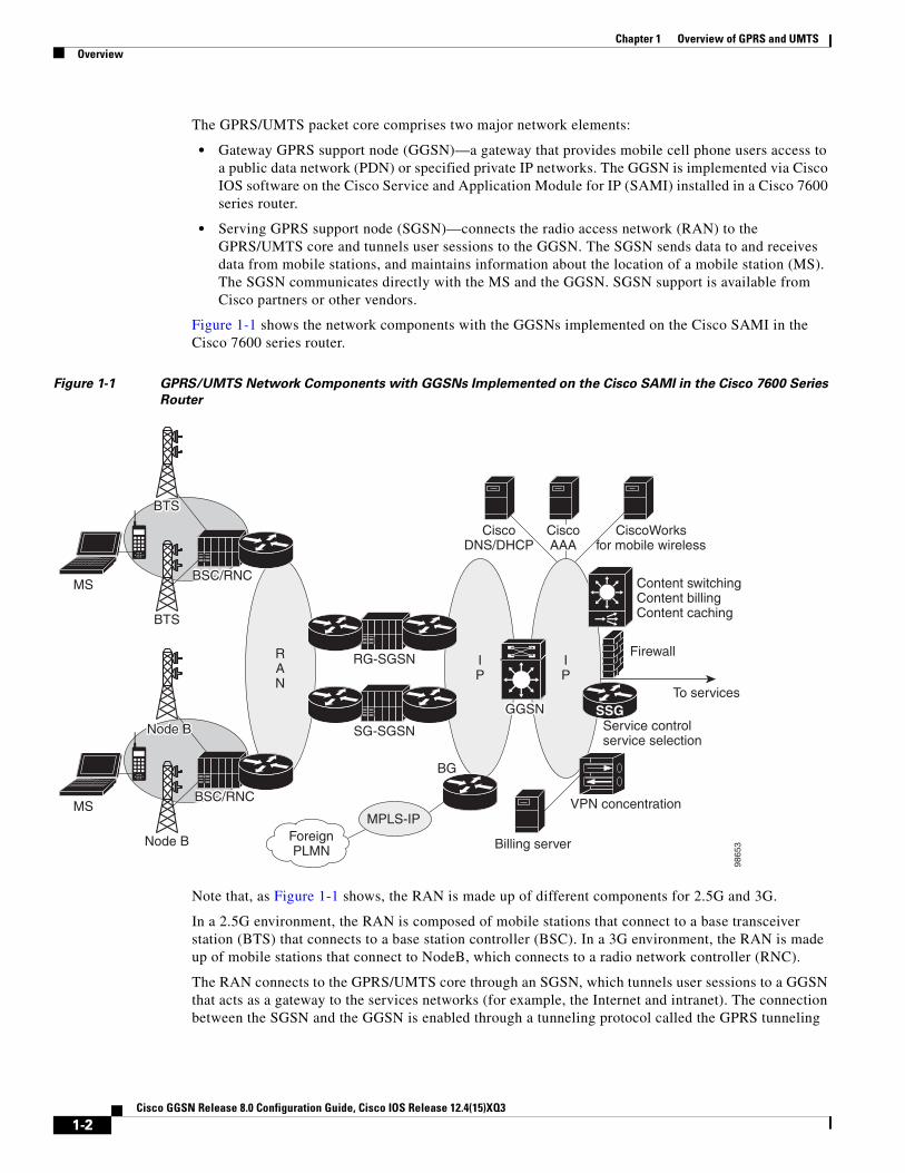
The GPRS/UMTS packet core comprises two major network elements:
• Gateway GPRS support node (GGSN)—a gateway that provides mobile cell phone users access to a public data network (PDN) or specified private IP networks. The GGSN is implemented via Cisco IOS software on the Cisco Service and Application Module for IP (SAMI) installed in a Cisco 7600 series router.
• Serving GPRS support node (SGSN)—connects the radio access network (RAN) to the GPRS/UMTS core and tunnels user sessions to the GGSN. The SGSN sends data to and receives data from mobile stations, and maintains information about the location of a mobile station (MS). The SGSN communicates directly with the MS and the GGSN. SGSN support is available from Cisco partners or other vendors.
Figure 1-1 shows the network components with the GGSNs implemented on the Cisco SAMI in the Cisco 7600 series router.
Figure 1-1 GPRS/UMTS Network Components with GGSNs Implemented on the Cisco SAMI in the Cisco 7600 Series
Router
Note that, as Figure 1-1 shows, the RAN is made up of different components for 2.5G and 3G.
In a 2.5G environment, the RAN is composed of mobile stations that connect to a base transceiver station (BTS) that connects to a base station controller (BSC). In a 3G environment, the RAN is made up of mobile stations that connect to NodeB, which connects to a radio network controller (RNC).
The RAN connects to the GPRS/UMTS core through an SGSN, which tunnels user sessions to a GGSN that acts as a gateway to the services networks (for example, the Internet and intranet). The connection between the SGSN and the GGSN is enabled through a tunneling protocol called the GPRS tunneling
RAN
IP
IP
SSG
ForeignPLMN
Node B
Node BNode BNode B
MSMPLS-IP
CiscoDNS/DHCP
RG-SGSN
SG-SGSN
Billing server
Firewall
Content switchingContent billingContent caching
To services
BG
VPN concentration
Service controlservice selection
CiscoWorksfor mobile wireless
BTSBTSBTS
BTS
MS
98
65
3
GGSNGGSNGGSN
CiscoAAA
BSC/RNCBSC/RNC
BSC/RNCBSC/RNC
1-2Cisco GGSN Release 8.0 Configuration Guide, Cisco IOS Release 12.4(15)XQ3

Chapter 1 Overview of GPRS and UMTSOverview
protocol (GTP)—GTP Version 0 (GTPv0) for 2.5G applications, and GTP Version 1 (GTPv1) for 3G applications. GTP is carried over IP. Multiple SGSNs and GGSNs within a network are referred to collectively as GPRS support nodes (GSNs).
Note Depending on the specific operator configuration, the RAN, the GPRS/UMTS core, and the services networks can be made up of IP or Multiprotocol Label Switching (MPLS) networks.
To assign mobile sessions an IP address, the GGSN uses the Dynamic Host Configuration Protocol (DHCP), Remote Authentication Dial-In User Service (RADIUS) server, or a local address pool defined specified on an access point configured on the GGSN. The GGSN can use a RADIUS server to authorize and authenticate remote users. DHCP and RADIUS services can be specified either at the global configuration level or for each access point configured on the GGSN.
With the Cisco SAMI installed in a Cisco 7600 series router, IPSec encryption is performed on the IPSec Virtual Private Network (VPN) Acceleration Services Module.
GPRS Interface Reference Model
The 2.5G GPRS and 3G UMTS standards use the term interface to label (or identify) the communication path between different network elements. The GPRS/UMTS standards define the requirements and characteristics of communication between different GPRS/UMTS network elements over these interfaces. These interfaces are commonly referred to in descriptions of GPRS/UMTS networks.
Figure 1-2 shows the primary interfaces that are implemented in the Cisco GGSN feature:
• Gn interface—Interface between GSNs within the same public land mobile network (PLMN) in a GPRS/UMTS network. GTP is a protocol defined on the Gn interface between GSNs in a GPRS/UMTS network.
• Gi interface—Reference point between a GPRS/UMTS network and an external packet data network.
• Ga interface—Interface between a GGSN and charging gateway (CG) in a GPRS/UMTS network.
Figure 1-2 GGSN Interfaces
Virtual Template Interface
To facilitate configuration of connections between the GGSN and SGSN, and the GGSN and PDNs, the Cisco IOS GGSN software uses an internal interface called a virtual template interface. A virtual template is a logical interface that is not tied directly to a specific interface, but that can be associated dynamically with a interface.
As with a physical interface on a router, you can assign an IP address to the virtual template interface. You can also configure IP routing characteristics on the virtual template interface. You are required to configure certain GPRS/UMTS-specific elements on the virtual template interface, such as GTP encapsulation (which is necessary for communicating with the SGSN) and the access list that the GGSN uses to determine which PDNs are accessible on the network.
SGSN
CG
GGSN
Gn interface
Ga interface
Gi interfacePDN
4691
3
1-3Cisco GGSN Release 8.0 Configuration Guide, Cisco IOS Release 12.4(15)XQ3

Chapter 1 Overview of GPRS and UMTSBenefits
Access Points
The GPRS/UMTS standards define a network identity called an access point name (APN). An APN identifies the service or network to which a user can connect from a GGSN in a GPRS/UMTS network.
To configure APNs, the Cisco IOS GGSN software uses the following configuration elements:
• Access point—Defines an APN and its associated access characteristics, including security and method of dynamic addressing.
• Access point list—Logical interface that is associated with the virtual template of the GGSN. The access-point list contains one or more access points.
• Access group—An additional level of security that is configured at an access point to control access to and from a PDN. When an MS is permitted access to the GGSN as defined by a traditional IP access list, the IP access group further defines whether access is permitted to the PDN (at the access point). The IP access group configuration can also define whether access from a PDN to an MS is permitted.
For more detailed information on access-point configuration, refer to the “Configuring Access Points on the GGSN” section on page 8-7.
BenefitsThe 2.5G GPRS technology provides the following benefits:
• Enables the use of a packet-based air interface over the existing circuit-switched GSM network, which allows greater efficiency in the radio spectrum because the radio bandwidth is used only when packets are sent or received
• Supports minimal upgrades to the existing GSM network infrastructure for network service providers who want to add GPRS services on top of GSM, which is currently widely deployed
• Supports enhanced data rates in comparison to the traditional circuit-switched GSM data service
• Supports larger message lengths than Short Message Service (SMS)
• Supports a wide range of access to data networks and services, including VPN/Internet service provider (ISP) corporate site access and Wireless Application Protocol (WAP).
In addition to the above, the 3G UMTS technology includes the following:
• Enhanced data rates of approximately
– 144 kbps—Satellite and rural outdoor
– 384 kbps—Urban outdoor
– 2048 kbps—Indoor and low-range outdoor
• Supports connection-oriented Radio Access Bearers with specified QoS, enabling end-to-end QoS
1-4Cisco GGSN Release 8.0 Configuration Guide, Cisco IOS Release 12.4(15)XQ3

Chapter 1 Overview of GPRS and UMTSNew Features in this Release
New Features in this ReleaseCisco GGSN Release 8.0, Cisco IOS Release 12.4(15)XQ, introduces support for the following features:
• GGSN-Initiated Update PDP Context Requests, page 1-5
• RADIUS Change of Authorization Message, page 1-5
• Downloadable QoS Profile, page 1-6
• PPP-Regeneration Scalability, page 1-6
• AAA Enhancements, page 1-6
• Anonymous User Access for PPP-Regeneration, page 1-7
• Downloadable Pool Name Support, page 1-7
• Direct Tunnel Support, page 1-7
• Configuring a Charging Source Interface, page 1-8
• Suppressing Echo Requests per SGSN, page 1-8
• iSCSI Transport Protocol Support, page 1-9
• MIB Enhancements, page 1-9
GGSN-Initiated Update PDP Context RequestsWith this release, a Cisco GGSN can send an Update PDP Context Request (as defined in 3GPP TR 29.060 v7.5.1, section 7.3.3) to an SGSN to negotiate the QoS of a PDP context.
An external entity, such as the Cisco Content Services Gateway (CSG) in an Gx environment, can push a new QoS profile to the GGSN to apply on a particular PDP context. The GGSN then pushes the changes to the RAN in an Update PDP Context Request to the SGSN.
Additionally, when a direct tunnel is being used for a PDP context, the GGSN sends an Update PDP Context Request to an SGSN in response to an error indication message from a Radio Network Controller (RNC).
For detailed information about GGSN-initiated Update PDP Context Requests, see the “Configuring Support for GGSN-Initiated Update PDP Context Requests” section on page 3-26.
RADIUS Change of Authorization MessageThe RADIUS Change of Authorization (CoA) message contains information for dynamically changing session authorizations. With Cisco GGSN Release 8.0, the GGSN utilizes the base Cisco IOS AAA to support the RADIUS CoA message, as defined by RFC 3576, but with an additional 3GPP QoS attribute indicates the updated QoS and the Acct-Session-ID to identify the PDP context.
The QoS vendor-specific attribute (VSA) is a string with bytes encoded with QoS attributes as defined by 3GPP TS 24.008, and the Accounting-session-id is a string using the standard attribute type 44.
The following is an example, using VSA vendor-ID 10415 code 5 string:
99-1333172B7BEAF52312C6C701
The CoA is received on port 1700.
1-5Cisco GGSN Release 8.0 Configuration Guide, Cisco IOS Release 12.4(15)XQ3

Chapter 1 Overview of GPRS and UMTSNew Features in this Release
For detailed information about AAA and RADIUS, see the Cisco IOS Security Configuration Guide, Release 12.4.
To ensure that the interim accounting record is generated as a part of the CoA procedure, confirm that the following exists:
• Globally, the aaa accounting update newinfo global configuration command has been configured.
• Under the APN, the aaa-accounting access-point configuration command has been configured with the interim update keyword option specified.
No commands have been introduced for the RADIUS CoA message support.
Downloadable QoS ProfileWith Release 8.0, the Cisco GGSN supports downloading QoS profiles from an AAA server.
If an APN is configured in non-transparent mode, a user is authenticated before the PDP context is created. GGSN sends an access-request to AAA server with parameters in the user provided PCO option (or using anonymous authentication if anonymous user is enabled on APN).
In the access-accept message from the RADIUS server, user-specific attributes such as the session and idle timeout values, can be downloaded and applied to the PDP context. In addition to these attributes, the Cisco GGSN supports downloading the QoS profile via the QoS VSA (as defined by 3GPP TS 24.0008). If a 3GPP QoS profile attribute is received from an AAA server in an access-accept message, the GGSN retrieves the attribute and applies it to the PDP context. If the attribute is not valid, or there is a format error in the attribute, the attribute is ignored and the SGSN requested QoS profile is used for QoS negotiation.
The 3GPP QoS attribute has a vendor-id of 10415 and code 5:
99-1333172B7BEAF52312C6C701
No commands have been introduced for the downloadable QoS profile support.
PPP-Regeneration ScalabilityThis release of the Cisco GGSN allows PDPs regenerated to a PPP session to run on software interface description blocks (IDBs). Allowing PPP sessions to run on software IDBs, can increase the number of supported sessions.
No commands have been introduced for the PPP-regeneration scalability support.
AAA EnhancementsCisco GGSN Release 8.0 utilizes the base Cisco IOS AAA functionality introduced to provide support for the following:
• Simultaneous method list level broadcast and wait accounting
• Per-session timer for interim accounting records (periodic accounting timer)
For detailed information about configuring broadcast and wait accounting to work together, see the “Configuring Simultaneous Broadcast and Wait Accounting” section on page 11-30.
For detailed information about configuring a periodic accounting timer, see “Periodic Accounting Timer” section on page 11-32.
1-6Cisco GGSN Release 8.0 Configuration Guide, Cisco IOS Release 12.4(15)XQ3

Chapter 1 Overview of GPRS and UMTSNew Features in this Release
Anonymous User Access for PPP-RegenerationAnonymous user access for PPP-regenerated PDPs is supported with Cisco GGSN Release 8.0 and later.
Anonymous user access support for PPP-regenerated PDPs enables PDPs to be created for users who cannot send a username and password (for example, WAP users).
When the anonymous user access-point user configuration command is configured under an APN that is configured for PPP regeneration, when a create PDP context request is received (for a PPP-regenerated PDP) that contains no username and password in the PCO IE, then the anonymous user configuration under that APN is sent to the LNS for authentication. However, if the PCO IE contains a username and password, the tunnel to the LNS is created using the supplied username and password, even though anonymous user is configured under the APN.
The username and password in the create PDP context request takes higher precedence than the anonymous user configuration.
No commands have been introduced or modified to support this feature.
For information about configuring anonymous user access under an APN, see the “Configuring Additional Real Access Point Options” section on page 8-20.
Downloadable Pool Name SupportWhen the ip-address-pool radius-client access-point configuration command is configured under an APN, if an address pool name is received as a part of the Access-Accept message while authenticating the user, the address pool is used to assign the IP address to the mobile station. If the Access-Accept message also includes an IP address, the IP address takes precedent over the address pool name, and the IP address in the Access-Accept message is used instead of being allocated from the pool.
No commands have been introduced or modified to support this feature on the GGSN.
To configure downloadable pool names, ensure that the ip-address pool access-point configuration command with the radius-client keyword option is configured under the APN as in the following example:
gprs access-point-list gprs access-point 3 access-point-name qos1.com ip-address-pool radius-client...
ip local pool pool1500 ipaddress ipaddress
For more information about the ip-address-pool access-point configuration command, see “Configuring Additional Real Access Point Options” section on page 8-20. For more information about configuring RADIUS, see the Cisco IOS Security Configuration Guide.
Direct Tunnel SupportDirect tunnels is an optional feature that enables an SGSN to establish a direct user plane tunnel between the radio network controller (RNC) and a GGSN.
The SGSN functions as the gateway between the RNC and the core network, handling both signaling traffic to keep track of the location of mobile devices, as well as the actual data packets being exchanged between the mobile device and the Internet.
1-7Cisco GGSN Release 8.0 Configuration Guide, Cisco IOS Release 12.4(15)XQ3

Chapter 1 Overview of GPRS and UMTSNew Features in this Release
Prior to Cisco GGSN Release 8.0, a tunnel could only exist between the GGSN and the SGSN and another tunnel between the SGSN and the RNC. With this tunnel configuration, all data packets have to pass through the SGSN, which has to terminate one tunnel, extract the packet, and put it into another tunnel. This process takes time and processing power.
With direct tunnel support, the SGSN can initiate a direct tunnel between the RNC and the GGSN and no longer have to process data packets. The SGSN will continue to managed location issues by modifying the tunnel if a mobile device moves to an area served by another RNC.
Specifically, direct tunnels processing is as follows:
1. The SGSN initiates the direct tunnel with an Update PDP Context Request that contains the following elements:
– Direct Tunnel Flags IE with the DTI bit set to 1.
– The RNC user traffic address
– Data TEID
2. The GGSN updates the RNC user traffic address and Data TEID and uses the updated information when sending G-PDUs for the MS.
3. If the GGSN receives an Error Indication message from the RNC user traffic address, the GGSN initiates an Update PDP Context Request that includes the Direct Tunnel Flags IE with the Error Indication bit set.
4. The GGSN drops subsequent packet to the MS address until the Update PDP Context response is received from the SGSN.
5. When the Update PDP Context Response is received from the SGSN, if the cause is “Request Accepted,” the PDP is preserved. If the cause is “Not Request Accepted,” the PDP is deleted locally.
Note Direct tunnel support does not apply to international roaming or when the SGSN is asked by a prepaid system to count the traffic flow.
No commands have been introduced or modified to support this feature on the GGSN.
Configuring a Charging Source InterfaceBy default, the global GTP virtual template interface is used for all charging messages. With this release of the Cisco GGSN, you can configure a loopback interface, and configure the GGSN to use that loopback interface for all charging messages. This feature enables charging network traffic to be segregated into a VRF or private VLAN. Once the charging source interface is specified, the GTP path to the charging gateways will be recreated with the new address obtained from the loopback interface.
For detailed information about configuring a charging source interface, see “Configuring a Charging Source Interface” section on page 6-5.
Suppressing Echo Requests per SGSNEcho requests can be disabled per SGSN and/or UDP port. This feature enables operators to selectively disable echo requests to GSNs that might not have the capability to respond to echo requests from the GGSN entirely, or only those echo requests received on certain UDP ports, while keeping the echo requests intact for the other SGSNs.
1-8Cisco GGSN Release 8.0 Configuration Guide, Cisco IOS Release 12.4(15)XQ3

Chapter 1 Overview of GPRS and UMTSFeatures from Previous Releases
When a new path is created, the GGSN checks to see if the path parameters, namely the destination address and port, matches any of the conditions configured when suppressing echo requests. If the parameters match, the GGSN sets the path echo interval to 0 for that path. Otherwise, the global path echo interval configuration is used to send echo requests.
For detailed information about suppressing echo requests, see “Suppressing Echo Requests per SGSN” section on page 3-25.
iSCSI Transport Protocol SupportWith Cisco GGSN Release 8.0 and later, you can configure the GGSN to backup G-CDRs to, and retrieve G-CDRs from, a storage target on a Storage Area Network (SAN) when a charging gateway is unavailable.
The Cisco GGSN utilizes the Cisco IOS software Small Computer Systems Interface over IP (iSCSI) support, as defined in RFC 3720, to enable G-CDR storage and retrieval from SAN storage.
For detailed information about configuring G-CDR back on an iSCSI target, see “Configuring G-CDR Backup and Retrieval using iSCSI” section on page 6-18.
MIB Enhancements New configuration, status, and statistic MIB objects have been added to support following Cisco GGSN Release 8.0 features:
• APN-level Periodic Accounting Timer
• PPP-Regeneration Scalability
• Direct tunnels
• Change of Authorization
• GGSN-initiated Update PDP Contexts
For detailed information about Configuring MIB support, see Appendix A, “Monitoring Notifications.”
Features from Previous ReleasesIn addition to the features introduced in this release, the Cisco GGSN also supports the following features and functionality introduced in prior releases:
• Release 99 (R99), Release 98 (R98), and Release 97 (R97) support and compliance
• GTPv0 and GTPv1 messaging
• IP Packet Data Protocol (PDP) and PPP PDP types
• Cisco Express Forwarding (CEF) switching for both GTPv0 and GTPv1, and for IP and PPP PDP types
• For GTPv1 PDPs, support of up to 11 secondary PDP contexts
• Virtual APNs
• VRF per APN support
• Multiple APNs per VRF
1-9Cisco GGSN Release 8.0 Configuration Guide, Cisco IOS Release 12.4(15)XQ3

Chapter 1 Overview of GPRS and UMTSFeatures from Previous Releases
• VPN support
– Generic routing encapsulation (GRE) tunneling
– Layer 2 Tunneling Protocol (L2TP) extension for PPP PDP type
– PPP Regeneration for IP PDP type
– 802.1Q virtual LANs (VLANs)
• Security features
– Duplicate IP address protection
– PLMN range checking
– Blocking of foreign mobile stations
– Anti-spoofing
– Mobile-to-mobile redirection
• Quality of service (QoS)
– UMTS classes and interworking with differentiated services (DiffServ)
– Delay QoS
– Canonical QoS
– GPRS QoS (R97/R98) conversion to UMTS QoS (R99) and the reverse
– Call Admission Control (CAC)
– Per-PDP policing
• Dynamic address allocation
– External DHCP server
– External RADIUS server
– Local pools
• Per-APN statistics
• Anonymous access
• RADIUS authentication and accounting
• Accounting
– Wait accounting
– Per-PDP accounting
– Authentication and accounting using RADIUS server groups mapped to APNs
– 3GPP vendor-specific attributes (VSAs) for IP PDP type
– Transparent mode accounting
– Class attribute
– Interim updates
– Session idle timer
– Packet of Disconnect (PoD)
• Dynamic Echo Timer
• GGSN interworking between 2.5G and 3G SGSNs with registration authority (RA) update from
– 2.5G to 2.5G SGSN
1-10Cisco GGSN Release 8.0 Configuration Guide, Cisco IOS Release 12.4(15)XQ3

Chapter 1 Overview of GPRS and UMTSFeatures from Previous Releases
– 2.5G to 3G SGSN
– 3G to 3G SGSN
– 3G to 2.5G SGSN
• Charging
– Time trigger
– Charging profiles
– Tertiary charging gateway
– Switchback to primary charging gateway
• Maintenance mode
• Multiple trusted PLMN IDs
• GGSN-IOS SLB messaging
• Session timeout
• High Speed Downlink Data Packet Access (HSDPA) and associated 3GPP R5 (as required).
• Enhanced Virtual APN
• New information elements (IEs) sent from the SGSN (user location, radio access technology [RAT], MS time zone (MSTZ), Customized Application for Mobile Enhanced Logic [CAMEL] charging information, and user location information IEs)
• GTP SLB stickiness
• P-CSCF Discovery
• Enhanced MIBs for Cisco Content Services Gateway (CSG) and Diameter Credit Control Application (DCCA)
1-11Cisco GGSN Release 8.0 Configuration Guide, Cisco IOS Release 12.4(15)XQ3

Chapter 1 Overview of GPRS and UMTSFeatures from Previous Releases
1-12Cisco GGSN Release 8.0 Configuration Guide, Cisco IOS Release 12.4(15)XQ3
Cisco GGSN Release 8.0
C H A P T E R2
Planning to Configure the GGSNThis chapter provides information that you should know before configuring a gateway GPRS support node (GGSN).
This chapter includes the following sections:
• Prerequisites, page 2-1
• Restrictions, page 2-9
• Additional References, page 2-10
PrerequisitesDepending on the platform on which you are implementing a GGSN, the prerequisites vary. The sections below provide general guidelines to follow before configuring a GGSN in your network:
• Before You Begin, page 2-1
• Platform Prerequisites, page 2-2
Before You BeginThe Cisco GGSN Release 8.0 is supported on the Cisco Service and Application Module for IP (SAMI) for the Cisco 7600 series router platform.
Before you begin to configure a GGSN, you should know which networks your mobile users will be allowed to access using the GGSN. After you identify the networks, you can plan the interfaces to configure for those networks, and plan the associated access points to those networks and configure them on the GGSN.
For example, you might want to provide user access to the Internet through a public data network (PDN), plus access to two private corporate intranets. In this case, you need to set up three access points—one to enable user access to the PDN, and one for each of the two private intranets.
2-1Configuration Guide, Cisco IOS Release 12.4(15)XQ3

Chapter 2 Planning to Configure the GGSNPrerequisites
Platform PrerequisitesWhen configuring GGSNs on the Cisco 7600 series router platform, ensure that requirements outlined in the following sections are met:
• Required Hardware and Software, page 2-2
• Required Base Configuration, page 2-3
Required Hardware and Software
Implementing a Cisco GGSN on the Cisco 7600 series Internet router platform requires the following hardware and software.
• Any module that has ports to connect to the network.
• Supervisor Engine 720, with a Multilayer Switch Feature Card, running Cisco IOS Release 12.2(33)SRB1 or later.
or
Cisco 7600 Series Supervisor Engine 32, with a Multilayer Switch Feature Card, running Cisco IOS Release 12.2(33)SRC and LCP ROMMON Version 12.2[121] on the Cisco SAMI.
For details on upgrading the Cisco IOS release running on the supervisor engine, refer to the “Upgrading to a New Software Release” section in the Release Notes for Cisco IOS Release 12.2SR. For information about verifying and upgrading the LCP ROMMON image on the Cisco SAMI, refer to the Cisco Service and Application Module for IP User Guide.
Note The Cisco IOS software required on the supervisor engine is dependent on the supervisor engine being used and the Cisco mobile wireless application running on the Cisco SAMI processors.
• Cisco Service and Application Module for IP (Cisco Product Number: WS-SVC-SAMI-BB-K9). The SAMI processors must be running Cisco IOS Release 12.4(15)XQ or later. The image is automatically loaded onto each processor during an image upgrade and supports both the 1 GB memory default and the 2 GB memory option ( Cisco Product Number: MEM-SAMI-6P-2GB[=]).
• IPSec VPN Services Module (for security)
Note Certain GGSN features, such as enhanced service-aware billing and GTP-session redundancy, require additional hardware and software.
GTP-Session Redundancy
In addition to the required hardware and software above, implementing GTP-Session Redundancy (GTP-SR) requires at minimum:
• In a one-router implementation, two Cisco SAMIs in the Cisco 7600 series router, or
• In a two-router implementation, one Cisco SAMI in each of the Cisco 7600 series routers.
Enhanced Service-Aware Billing
In addition to the required hardware and software, implementing enhanced service-aware billing requires an additional Cisco SAMI running the Cisco Content Services Gateway - 2nd Generation software in each Cisco 7600 series router.
2-2Cisco GGSN Release 8.0 Configuration Guide, Cisco IOS Release 12.4(15)XQ3

Chapter 2 Planning to Configure the GGSNPrerequisites
Required Base Configuration
After connectivity has been established from the switch to the different elements in your network, ensure that you complete the following base configuration before implementing and customizing GGSNs on the Cisco SAMI:
On the supervisor engine, ensure that:
1. A Layer-3–routed VLAN for each of the GGSN interfaces has been created. Specifically, create a VLAN for the following interfaces:
– Gn VLAN—Interconnects the Gn interfaces.
– Ga VLAN—Interconnects the Ga interfaces.
– AAA/OAM/DHCP VLAN—Interconnects the GGSN interfaces used for AAA, Operation, Administration, and Maintenance (OAM), and DHCP functions.
– One VLAN per APN Gi interface
You can configure the VLANs from VLAN database mode or global configuration mode. You cannot configure extended-range VLANs in VLAN database mode. You can configure extended-range VLANs only in global configuration mode.
Note RPR+ redundancy does not support configurations entered in VLAN database mode. If you have a high-availability configuration with redundant Supervisor modules using RPR(+), configure the VLANs in global configuration mode and not through the VLAN database mode; otherwise, the VLAN information will not be synchronized to the redundant Supervisor module.
To configure a VLAN from global configuration mode:
Sup#conf terminal Enter configuration commands, one per line. End with CNTL/Z. Sup(config)#vlan 222 Sup(config-vlan)#end Sup#
In the preceding example, VLAN 222 is a Layer 2–switched VLAN. The subnet associated with it is not known by the supervisor engine routing table. To configure VLAN 222 as a Layer 3–switched VLAN (or routed VLAN), configure a VLAN 222 interface on the supervisor engine and assign an IP address to the interface:
Sup# configure terminalSup(config)# interface vlan222Sup(config-if)# ip address n.n.n.n maskSup(config-if)# no ip redirects
The following is an example of the VLAN configuration on the supervisor engine:
Sup# show running-config!. . .vlan 103,110,160,200,300-301,310 !!interface Vlan103 description Gn VLAN ip address 10.20.21.1 255.255.255.0 no ip redirects!interface Vlan110 description OAM/AAA/DHCP VLAN
2-3Cisco GGSN Release 8.0 Configuration Guide, Cisco IOS Release 12.4(15)XQ3

Chapter 2 Planning to Configure the GGSNPrerequisites
ip address 10.20.50.1 255.255.255.0 no ip redirects!interface Vlan200 description Ga Charging VLAN no ip address no ip redirects!interface Vlan310 description VLAN for APN Internet ip address 10.20.51.1 255.255.255.0
For detailed information on configuring VLANs, see the Cisco 7600 Series Cisco IOS Software Configuration Guide.
2. The Cisco IOS software server load balancing (SLB) feature is installed and configured for GTP load balancing. For more information, see the IOS Server Load Balancing feature module and Chapter 13, “Configuring Load Balancing on the GGSN.”
3. Permit traffic to the SAMI by enabling multiple switch virtual interfaces (SVIs), assiging the VLANs to a VLAN group, and then assigning the VLAN groups to the SAMI using the following commands:
!...!svclc multiple-vlan-interfacessvclc module 7 vlan-group 71, 73svclc vlan-group 71, 71svclc vlan-group 73, 95, 100, 101!...!
Note VLAN IDs must be consistent be the same in the supervisor engine and Cisco SAMI configurations. For more information about configuring the Cisco SAMI, refer the Cisco Service and Application Module for IP User Guide.
4. A static route is configured to each GGSN instance configured on the Cisco SAMI:
!...!ip route 10.20.30.1 255.255.255.255 10.20.21.20ip route 10.20.30.2 255.255.255.255 10.20.21.21ip route 10.20.30.3 255.255.255.255 10.20.21.22ip route 10.20.30.4 255.255.255.255 10.20.21.23ip route 10.20.30.5 255.255.255.255 10.20.21.24!...
2-4Cisco GGSN Release 8.0 Configuration Guide, Cisco IOS Release 12.4(15)XQ3

Chapter 2 Planning to Configure the GGSNPrerequisites
On each GGSN instance on the Cisco SAMI, ensure that:
1. A static route is configured to the supervisor engine.
!...!ip route 0.0.0.0.0 0.0.0.0 10.20.21.1...!
2. A subinterface, on which 802.1Q encapsulation is enabled, is configured to each of the VLANs that you created on the supervisor engine.
The following is an example of a Ga/Gn subinterface configuration on the GGSN to VLAN 103 configured on the supervisor engine:
!...interface GigabitEthernet0/0.2 description Ga/Gn Interface encapsulation dot1Q 101 ip address 10.1.1.72 255.255.255.0 no cdp enable...!
For detailed information on configuring:
– Ga subinterfaces, see the “Configuring an Interface to the Charging Gateway” section on page 6-1.
– Gn subinterfaces, see the “Configuring an Interface to the SGSN” section on page 8-1.
– Gi subinterfaces, see the “Configuring an Interface to a PDN” section on page 8-12.
Configuration Examples
The following are base configuration examples for the supervisor engine and the GGSN instance running on the Cisco SAMI.
Supervisor Engine
hostname 7600-a!boot system flash boot device module 7 cf:4!svclc multiple-vlan-interfacessvclc module 7 vlan-group 71, 73svclc vlan-group 71, 71svclc vlan-group 73, 95, 100, 101vtp mode transparentredundancy mode rpr-plus main-cpu auto-sync running-config auto-sync standard!power redundancy-mode combined!!vlan 1 vlan1 1002
2-5Cisco GGSN Release 8.0 Configuration Guide, Cisco IOS Release 12.4(15)XQ3

Chapter 2 Planning to Configure the GGSNPrerequisites
vlan2 1003!vlan 2 name SNIFFER!vlan 71,95 !vlan 100 name Internal_Gi_for_GGSN-SAMI!vlan 101 name Internal_Gn/Ga!vlan 165!vlan 302 name Gn_1!vlan 303 name Ga_1!vlan 1002 vlan1 1 vlan2 1003!vlan 1003 vlan1 1 vlan2 1002 parent 1005 backupcrf enable!vlan 1004 bridge 1 stp type ibm!vlan 1005 bridge 1!interface FastEthernet8/22 description To SGSN no ip address switchport switchport access vlan 302!interface FastEthernet8/23 description To CGF no ip address switchport switchport access vlan 302!interface FastEthernet8/26 description To DHCP/RADIUS Servers no ip address switchport switchport access vlan 95!interface FastEthernet8/31 description To BackBone no ip address switchport switchport access vlan 71!interface FastEthernet9/32 description To CORPA
2-6Cisco GGSN Release 8.0 Configuration Guide, Cisco IOS Release 12.4(15)XQ3

Chapter 2 Planning to Configure the GGSNPrerequisites
no ip address switchport switchport access vlan 165 no cdp enable!!interface Vlan1 no ip address shutdown!interface Vlan71 description VLAN to tftpserver ip address 1.7.46.65 255.255.0.0!interface Vlan95 description VLAN for RADIUS and DHCP ip address 10.2.25.1 255.255.255.0!interface Vlan100 description Internal VLAN SUP-to-SAMI Gi ip address 10.1.2.1 255.255.255.0!interface Vlan101 description VLAN to GGSN for GA/GN ip address 10.1.1.1 255.255.255.0!interface Vlan165 description VLAN to CORPA ip address 165.1.1.1 255.255.0.0!interface Vlan302 ip address 40.0.2.1 255.255.255.0!interface Vlan303 ip address 40.0.3.1 255.255.255.0!router ospf 300 log-adjacency-changes summary-address 9.9.9.0 255.255.255.0 redistribute static subnets route-map GGSN-routes network 40.0.2.0 0.0.0.255 area 300 network 40.0.3.0 0.0.0.255 area 300!ip classlessip route 9.9.9.72 255.255.255.255 10.1.1.72ip route 9.9.9.73 255.255.255.255 10.1.1.73ip route 9.9.9.74 255.255.255.255 10.1.1.74ip route 9.9.9.75 255.255.255.255 10.1.1.75ip route 9.9.9.76 255.255.255.255 10.1.1.76ip route 110.72.0.0 255.255.0.0 10.1.1.72ip route 110.73.0.0 255.255.0.0 10.1.1.73ip route 110.74.0.0 255.255.0.0 10.1.1.74ip route 110.75.0.0 255.255.0.0 10.1.1.75ip route 110.76.0.0 255.255.0.0 10.1.1.76!access-list 1 permit 9.9.9.0 0.0.0.255!route-map GGSN-routes permit 10 match ip address 1!
2-7Cisco GGSN Release 8.0 Configuration Guide, Cisco IOS Release 12.4(15)XQ3

Chapter 2 Planning to Configure the GGSNPrerequisites
GGSN Instance on a Cisco SAMI Processor
service gprs ggsn!hostname 7600-7-2!ip cef!interface Loopback0 description USED FOR DHCP gateway ip address 110.72.0.2 255.255.255.255!interface Loopback100 description GPRS GTP V-TEMPLATE IP ADDRESS ip address 9.9.9.72 255.255.255.0!interface GigabitEthernet0/0 no ip address!interface GigabitEthernet0/0.1 description Gi encapsulation dot1Q 100 ip address 10.1.2.72 255.255.255.0!interface GigabitEthernet0/0.2 description Ga/Gn Interface encapsulation dot1Q 101 ip address 10.1.1.72 255.255.255.0 no cdp enable!interface GigabitEthernet0/0.71 description TFTP or Backbone encapsulation dot1Q 71 ip address 1.7.46.72 255.255.0.0!interface GigabitEthernet0/0.95 description CNR and CAR encapsulation dot1Q 95 ip address 10.2.25.72 255.255.255.0!interface Virtual-Template1 description GTP v-access ip unnumbered Loopback100 encapsulation gtp gprs access-point-list gprs!ip classlessip route 0.0.0.0 0.0.0.0 10.1.2.1ip route 40.1.2.1 255.255.255.255 10.1.1.1ip route 40.1.3.10 255.255.255.255 10.1.1.1ip route 40.2.2.1 255.255.255.255 10.1.1.1ip route 40.2.3.10 255.255.255.255 10.1.1.1ip route 40.3.2.3 255.255.255.255 10.1.1.1ip route 40.4.2.3 255.255.255.255 10.1.1.1!gprs access-point-list gprs access-point 1 access-point-name CORPA.com ip-address-pool dhcp-proxy-client aggregate auto dhcp-server 10.2.25.90 dhcp-gateway-address 110.72.0.2 !
2-8Cisco GGSN Release 8.0 Configuration Guide, Cisco IOS Release 12.4(15)XQ3

Chapter 2 Planning to Configure the GGSNRestrictions
RestrictionsWhen configuring a Cisco GGSN, observe the following:
• The Cisco GGSN does not support the Cisco Express Forwarding (CEF) neighbor resolution optimization feature, which is enabled by default. Therefore, to avoid the possibility of incomplete adjacency on VLAN interfaces for the redirected destination IP address and an impact to the upstream traffic flow for PDP sessions upon startup, ensure that you configure the no ip cef optimize neighbor resolution command.
• The number of PDP contexts supported on a GGSN is dependent on the memory and platform in use and the GGSN configuration (for example, whether or not a method of Point to Point Protocol [PPP] has been configured to forward packets beyond the terminal equipment and mobile termination, whether Dynamic Feedback Protocol [DFP] is being used or the memory protection feature is enabled, and what rate of PDP context creation will be supported).
Note DFP weighs PPP PDPs against IP PDPs with one PPP PDP equal to eight IP PDPs. One IPv6 PDP equals 8 IPv4 PDPs.
Table 2-1 lists the maximum number of PDP contexts the Cisco SAMI with the 1 GB memory option can support. Table 2-2 lists the maximum number the Cisco SAMI with the 2 GB memory option can support.:
• To avoid issues with high CPU usage, we recommend the following configurations:
– To reduce the CPU usage during bootup, disable logging to the console terminal by configuring the no logging console global configuration command.
Table 2-1 Number of PDPs Supported in 1 GB SAMI
PDP Type Maximum Number per GGSN Maximum Number per SAMI1
1. Maximum number per SAMI on which six GGSNs are configured.
IPv4 60,000 360,000
IPv6 8,000 48,000
PPP Regeneration 16,000 96,000
PPP 8,000 48,000
Table 2-2 Number of PDPs Supported in 2 GB SAMI
PDP Type Maximum Number per GGSN Maximum Number per SAMI1
1. Maximum number per SAMI on which six GGSNs are configured.
IPv4 128,000 768,000
IPv6 16,000 96,000
PPP Regeneration 32,000 192,000
PPP 16,000 96,000
2-9Cisco GGSN Release 8.0 Configuration Guide, Cisco IOS Release 12.4(15)XQ3

Chapter 2 Planning to Configure the GGSNAdditional References
– To ensure that the HSRP interface does not declare itself active until it is ready to process a peer’s Hello packets, configure the delay period before the initialization of HSRP groups with the standby delay minimum 100 reload 100 interface configuration command under the HRSP interface.
– To minimize issues with high CPU usage for additional reasons, such as periods of high PPP PDP processing (creating and deleting), disable the notification of interface data link status changes on all virtual template interfaces of the GGSN using the no logging event link-status interface configuration command.
! interface Virtual-Template1 description GGSN-VT ip unnumbered Loopback0 encapsulation gtp no logging event link-statusgprs access-point-list gprs end
For implementation of a service-aware GGSN, the following additional important notes, limitations, and restrictions apply:
• RADIUS accounting is enabled between the CSG2 and GGSN to populate the Known User Entries Table (KUT) entries with the PDP context user information.
• CSG2 must be configured with the QS addresses of all the GGSN instances.
• Service IDs on the CSG2 are configured as numeric strings that match the category IDs on the Diameter Credit Control Application (DCCA) server.
• If RADIUS is not being used, the Cisco CSG2 is configured as a RADIUS endpoint on the GGSN.
• On the SGSN, the values configured for the number GTP N3 requests and T3 retransmissions must be larger than the sum of all possible server timers (RADIUS, DCCA, and CSG2).
Specifically the SGSN N3*T3 must be greater than:
2 x RADIUS timeout + N x DCCA timeout + CSG2 timeout
where:
– 2 is for both authentication and accounting.
– N is for the number of diameter servers configured in the server group.
Note Configuring a N3* T3 lower than the default might impact slow TCP-based charging paths.
Additional ReferencesFor additional information related to implementing basic connectivity, see the following sections:
• Related Documents, page 2-10
• Standards, page 2-11
• MIBS, page 2-12
• RFCs, page 2-12
• Technical Assistance, page 2-12
2-10Cisco GGSN Release 8.0 Configuration Guide, Cisco IOS Release 12.4(15)XQ3

Chapter 2 Planning to Configure the GGSNAdditional References
Related Documents • Cisco IOS Configuration Fundamentals Configuration Guide, Release 12.4
• Cisco IOS Configuration Fundamentals Command Reference, Release 12.4
• Cisco IOS Dial Technologies Configuration Guide, Release 12.4
• Cisco IOS Dial Technologies Command Reference, Release 12.4
• Cisco IOS Interface and Hardware Component Configuration Guide, Release 12.4
• Cisco IOS Interface and Hardware Component Command Reference, Release 12.4
• Cisco IOS IP Mobility Configuration Guide, Release 12.4
• Cisco IOS IP Mobility Command Reference, Release 12.4
• Cisco IOS IP Multicast Configuration Guide, Release 12.4
• Cisco IOS IP Multicast Command Reference, Release 12.4
• Cisco IOS IP Routing Protocols Configuration Guide, Release 12.4
• Cisco IOS IP Routing Protocols Command Reference, Release 12.4
• Cisco IOS IP Switching Configuration Guide, Release 12.4
• Cisco IOS IP Switching Command Reference, Release 12.4
• Cisco IOS IPv6 Configuration Guide, Release 12.4
• Cisco IOS IPv6 Command Reference, Release 12.4
• Cisco IOS LAN Switching Configuration Guide, Release 12.4
• Cisco IOS LAN Switching Command Reference, Release 12.4
• Cisco IOS Mobile Wireless Packet Data Serving Node Configuration Guide, Release 12.4
• Cisco IOS Mobile Wireless Packet Data Serving Node Command Reference, Release 12.4
• Cisco IOS Network Management Configuration Guide, Release 12.4
• Cisco IOS Network Management Command Reference, Release 12.4
• Cisco IOS Optimized Edge Routing Configuration Guide, Release 12.4
• Cisco IOS Optimized Edge Routing Command Reference, Release 12.4
• Cisco IOS Quality of Service Solutions Configuration Guide, Release 12.4
• Cisco IOS Quality of Service Solutions Command Reference, Release 12.4
• Cisco IOS Security Configuration Guide, Release 12.4
• Cisco IOS Security Command Reference, Release 12.4
• Cisco Multi-Processor WAN Application Module Installation and Configuration Note
StandardsCisco GGSN Release 8.0 supports the following Third Generation Partnership Program (3GPP) standards and is backward compatible with prior 3GPP Technical Specifications (TS):
2-11Cisco GGSN Release 8.0 Configuration Guide, Cisco IOS Release 12.4(15)XQ3

Chapter 2 Planning to Configure the GGSNAdditional References
Note Cisco GGSN Release 8.0 provides limited support on some sections of the TSs listed above.
The GGSN interfaces comply with the following SMG (Special Mobile Group) standards:
• Ga interface—SMG#28 R99
• Gn interface—SMG#31 R98
MIBS • CISCO-GGSN-EXT-MIB
• CISCO-GGSN-MIB
• CISCO-GGSN-QOS-MIB
• CISCO-GGSN-SERVICE-AWARE-MIB
• CISCO-GPRS-ACC-PT-MIB
• CISCO-GPRS-CHARGING-MIB
• CISCO-GPRS-GTP-CAPABILITY-MIB
• CISCO-GTP-MIB
RFCs • RFC 1518, An Architecture for IP Address Allocation with CIDR
• RFC 1519, Classless Inter-Domain Routing (CIDR): an Address Assignment and Aggregation Strategy
• RFC 1661, The Point-to-Point Protocol (PPP)
• RFC 2461, Neighbor Discovery for IP Version 6 (IPv6)
• RFC 2462, IPv6 Stateless Address Autoconfiguration
• RFC 2475, An Architecture for Differentiated Services
• RFC 3162, RADIUS and IPv6
• RFC 3588, Diameter Base Protocol
• RFC 3720, Internet Small Computer Systems Interface (iSCSI)
Table 2-3 Third Generation Partnership Program (3GPP) Standards Supported by Cisco GGSN Release 8.0
3G TS# Title Release GGSN Release 8.0
29.060 GTP across Gn and Gp 7 8.1.0
29.061 Interworking with PDN 7 7.5.0
32.015 Charging 99 3.12.0
32.215 Charging 5 5.9.0
32.251 Charging 7 7.5.1
2-12Cisco GGSN Release 8.0 Configuration Guide, Cisco IOS Release 12.4(15)XQ3

Chapter 2 Planning to Configure the GGSNAdditional References
• RFC 4006 Diameter Credit-Control Application
Technical AssistanceThe Cisco Technical Support website contains thousands of pages of searchable technical content, including links to products, technologies, solutions, technical tips, and tools. Registered Cisco.com users can log in from this page to access even more content.
http://www.cisco.com/techsupport
2-13Cisco GGSN Release 8.0 Configuration Guide, Cisco IOS Release 12.4(15)XQ3

Chapter 2 Planning to Configure the GGSNAdditional References
2-14Cisco GGSN Release 8.0 Configuration Guide, Cisco IOS Release 12.4(15)XQ3

Cisco GGSN Release 8.0
C H A P T E R3
Configuring GTP Services on the GGSNThis chapter describes how to configure a gateway GPRS service node (GGSN) and how to configure GPRS tunneling protocol (GTP) options.
For a complete description of the GGSN commands in this chapter, refer to the Cisco GGSN Command Reference for the Cisco GGSN release you are using.
To locate documentation of other commands that appear in this chapter, use the command reference master index or search online. See the “Related Documents” section on page 2-10 for a list of the other Cisco IOS software documentation that might be helpful while configuring the GGSN.
This chapter includes the following sections:
• GTP Overview, page 3-1
• Configuring GGSN Services, page 3-2
• Configuring Echo Timing on a GGSN, page 3-4
• Customizing the GGSN Configuration, page 3-14
• Using the Service-Mode Function, page 3-27
• Monitoring and Maintaining GTP on the GGSN, page 3-32
• Configuration Examples, page 3-33
GTP OverviewGTP is the protocol used to tunnel multi-protocol packets through the general packet radio service/Universal Mobile Telecommunication System (GPRS/UMTS) network. It is defined on the Gn interface as the protocol between GSNs in the GPRS/UMTS backbone network.
The Cisco GGSN simultaneously supports both GTP Version 0 (GTP v0) and GTP Version 1 (GTP v1). GPRS R97/R98 uses GTP Version 0, and UMTS R99 uses GTP v1.
The GGSN automatically selects the GTP version to use according to the capabilities of the SGSN.
3-1Configuration Guide, Cisco IOS Release 12.4(15)XQ3

Chapter 3 Configuring GTP Services on the GGSNConfiguring GGSN Services
Configuring GGSN ServicesThe Cisco GGSN software uses a logical interface called a virtual template interface to configure an instance of Cisco IOS software running on a Cisco Service and Application Module for IP (SAMI) processor as a GGSN.
This section describes the primary tasks you need to complete when configuring for GGSN services. The subsequent configuration tasks describe how to establish connectivity from the GGSN to the serving GPRS support node (SGSN) and public data networks (PDNs) once the Cisco IOS instance on the Cisco SAMI processor has been configured as a GGSN.
The following requirements must be met when configuring a GGSN:
• Configure only a single GGSN entity per instance of Cisco IOS software, using the service gprs ggsn global configuration command. Up to six GGSNs can be configured on one Cisco SAMI—one GGSN per processor.
• On each GGSN, configure only a single virtual template interface (as virtual template number 1) with GTP encapsulation.
• Ensure that the memory protection threshold has been configured appropriately, according to the router and memory size. For information on configuring the memory protection threshold, see “Configuring the GGSN Memory Threshold” section on page 6-6.
GGSN Services Configuration Task ListTo configure a Cisco SAMI processor that is running an instance of Cisco IOS GGSN software for GGSN services, perform the following tasks:
• Enabling GGSN Services, page 3-2
• Creating a Loopback Interface, page 3-3
• Creating a Virtual Template Interface for GGSN, page 3-3
• Enabling CEF Switching, page 3-4
Enabling GGSN ServicesUsing the service gprs ggsn global configuration command, configure only a single GGSN entity per Cisco SAMI processor.
To enable GGSN services, use the following command in global configuration mode:
Command PurposeRouter(config)# service gprs ggsn Specifies that the Cisco IOS software instance
functions as a GGSN.
3-2Cisco GGSN Release 8.0 Configuration Guide, Cisco IOS Release 12.4(15)XQ3

Chapter 3 Configuring GTP Services on the GGSNConfiguring GGSN Services
Creating a Loopback InterfaceRather than directly configuring an IP address on the virtual template, we recommend that you create a loopback interface and then associate the loopback interface IP address to the virtual template used for GTP encapsulation using the ip unnumbered loopback interface configuration command.
Note If the IP address of the loopback interface is not assigned to the virtual template interface using the ip unnumbered loopback command, packets will not be CEF-switched and performance will be affected.
A loopback interface is a software-only interface that emulates an interface that is always up. It is a virtual interface that is supported on all platforms. The interface number is the number of the loopback interface that you want to create or configure. There is no limit to the number of loopback interfaces that you can create. A GGSN uses loopback interfaces to support the configuration of several different features.
To create a loopback interface, use the following commands in global configuration mode:
Creating a Virtual Template Interface for GGSNConfigure only a single virtual template interface (as virtual template number 1) with GTP encapsulation on a GGSN.
To create a virtual template interface for GGSN, use the following command, beginning in global configuration mode:
Command Purpose
Step 1 Router(config)# interface loopback number Creates a loopback interface. A loopback interface is a virtual interface that is always up.
Step 2 Router(config-if)# ip address ip-address mask Assigns an IP address to the loopback interface.
Command Purpose
Step 1 Router(config)# interface virtual-template number Creates a virtual template interface, where number identifies the virtual template interface. This command takes you to interface configuration mode.
Note A GGSN supports only a single virtual template for the GTP virtual interface.
Step 2 Router(config-if)# ip unnumber loopback number Assigns the previously defined loopback IP address to the virtual template interface.
Step 3 Router(config-if)# encapsulation gtp Specifies GTP as the encapsulation type for packets transmitted over the virtual template interface.
Step 4 Router(config-if)# gprs access-point-list gprs Specifies a name for a new access point list, or references the name of the existing access point list, and enters access-point list configuration mode.
3-3Cisco GGSN Release 8.0 Configuration Guide, Cisco IOS Release 12.4(15)XQ3
Chapter 3 Configuring GTP Services on the GGSNConfiguring Echo Timing on a GGSN
Enabling CEF SwitchingCEF switching uses a forwarding information base (FIB) table and an adjacency table to accomplish packet switching. The adjacency table is indexed by Layer 3 network addresses and contains the corresponding Layer 2 information to forward a packet.
CEF switching eliminates the use of the route-cache table, and the overhead that is required in aging out its table entries and repopulating the table. The FIB table mirrors the entire contents of the IP routing table, which eliminates the need for a route-cache table.
For more information about switching paths, refer to the Cisco IOS Switching Services Configuration Guide.
When you enable CEF switching globally on the GGSN, all interfaces on the GGSN are automatically enabled for CEF switching.
Note To ensure that CEF switching functions properly, wait a short period of time before enabling CEF switching after it has been disabled using the no ip cef command.
To enable CEF switching on the GGSN, use the following commands beginning in global configuration mode:
Configuring Echo Timing on a GGSNGGSN uses echo timing to determine whether an SGSN or external charging gateway is active.
For a GTP path to be active, the SGSN needs to be active. To determine that an SGSN is active, the GGSN and SGSN exchange echo messages. Although the GGSN supports different methods of echo message timing, the basic echo flow begins when the GGSN sends an echo request message to the SGSN. The SGSN sends a corresponding echo response message back to the GGSN.
If the GGSN does not receive a response after a certain number of retries (a configurable value), the GGSN assumes that the SGSN is not active. This indicates a GTP path failure, and the GGSN clears all PDP context requests associated with that path.
Command PurposeRouter(config)# ip cef Enables CEF on the GGSN.
3-4Cisco GGSN Release 8.0 Configuration Guide, Cisco IOS Release 12.4(15)XQ3

Chapter 3 Configuring GTP Services on the GGSNConfiguring Echo Timing on a GGSN
This section describes the different methods of echo timing that are supported on the GGSN and how to configure them. It includes the following topics:
• Overview of the Echo Timing on the GGSN, page 3-5
• Echo Timing Configuration Task List, page 3-10
• Verifying the Echo Timing Configuration, page 3-12
• Dynamic Echo Timer Configuration Example, page 3-34
Overview of the Echo Timing on the GGSNThe GGSN supports two different means of echo timing—the default echo timer and the dynamic echo timer. Only a single timer can be in use at any time on the GGSN. The following sections describe these two timers:
• Overview of the Default Echo Timer, page 3-5
• Overview of the Dynamic Echo Timer, page 3-7
Note For simplicity, this document describes the operation of echo timing between the GGSN and an SGSN. If an external charging gateway is in use in the GPRS/UMTS network, the GGSN uses the same type of echo timers to maintain the charging gateway path.
Overview of the Default Echo Timer
The default echo timer is enabled on the GGSN automatically. However, you can choose to enable the dynamic echo timing method as an alternative.
When you are using the default echo timer on the GGSN, the following commands apply:
• gprs gtp n3-requests—Specifies the maximum number of times that the GGSN attempts to send a echo-request message. The default is 5 times.
• gprs gtp path-echo-interval—Specifies the number of seconds that the GGSN waits for a response from an SGSN or external charging gateway, and, after receiving a response, the number of seconds the GGSN waits before sending the next echo-request message. The default is 60 seconds.
• gprs gtp t3-response—Specifies the initial number of seconds that the GGSN waits before resending a signaling request message when a response to a request has not been received. This time is doubled for every retry. The default is 1 second.
Figure 3-1 shows the default echo request sequence when a response is successfully received within the specified path echo interval. If the GGSN receives the echo response within the path echo interval (as specified in the gprs gtp path-echo-interval command; the default is 60 seconds), it sends another echo request message after 60 seconds (or whatever time was configured in the gprs gtp path-echo-interval command). This message flow continues as long as the GGSN receives an echo response message from the SGSN within the specified path echo interval.
3-5Cisco GGSN Release 8.0 Configuration Guide, Cisco IOS Release 12.4(15)XQ3

Chapter 3 Configuring GTP Services on the GGSNConfiguring Echo Timing on a GGSN
Figure 3-1 Default GTP Path Echo Interval Request Sequence in Path Success Mode
Figure 3-2 shows the default echo request sequence when the GGSN fails to receive a response to its echo request within the specified path echo interval. If the GGSN fails to receive an echo response message from the SGSN within the path echo interval, it resends echo request messages until the N3-requests counter is reached (as specified by the gprs gtp n3-requests command; the default is 5). Because the initial request message is included in the N3-requests counter, the total number of retries is N3 - 1. The T3 timer increases by a factor of 2 for each retry (the factor value is not configurable).
Figure 3-2 Default Echo Timing Request Sequence in Path Failure Mode
For example, if N3 is set to the default of 5, and T3 is set to the default of 1 second, the GGSN will resend 4 echo request messages (the initial request + 4 retries= 5). If the GGSN does not receive an echo response from the SGSN during the 60-second path echo interval, then the GGSN immediately sends the first echo request retry message upon expiration of the path echo interval. The T3 time increases for each additional echo request, by a factor of 2 seconds, as long as the GGSN does not receive an echo response. So, the GGSN resends another message in 2 seconds, 4 seconds, and 8 seconds. After the 5th message, the GGSN waits for a final period of 16 seconds for an echo response.
SGSN
GGSN
Echo Request
Echo Request
Echo Response
5900
1
60 seconds(gprs gtp path-echo-interval)
60 seconds(gprs gtp path-echo-interval)
SGSN
GGSN
Echo Request
60 seconds(gprs gtp path-echo-interval)
2 seconds
4 seconds
8 seconds
16 seconds
Echo Request Retry
No echo response received
Echo Request Retry
Echo Request Retry
Echo Request Retry
gprs gtp n3-requests 5900
2
1
2
3
4
5
3-6Cisco GGSN Release 8.0 Configuration Guide, Cisco IOS Release 12.4(15)XQ3

Chapter 3 Configuring GTP Services on the GGSNConfiguring Echo Timing on a GGSN
If the GGSN fails to receive an echo response message from the SGSN within the time period of the N3-requests counter, it deletes all of the PDP contexts and clears the GTP path. For this example, the total elapsed time from when the first request message is sent to when PDP contexts are cleared is
60 + 2 + 4 + 8 + 16 = 90 seconds
where 60 is the initial value of the path echo interval, and the remaining 4 time periods are the increments of the T3 timer for the subsequent retries. The path is cleared after another 60-second period, or 150 seconds.
If the GGSN receives an echo response within the N3 x T3 transmission period, it goes back to success mode for its echo request sequences.
Figure 3-3 shows the GGSN receiving an echo response message within N3 x T3 retransmissions of an echo request. In this scenario, the GGSN sent an initial echo request followed by 4 retries for a total of 5 requests, according to the default setting of 5 N3 requests. The GGSN receives the echo response after the 5th and final retry, within the remaining 16 seconds. Now the GGSN is back in success mode, and it waits 60 seconds (the value of the gprs gtp path-echo-interval command) before sending the next echo request message.
Figure 3-3 Default Echo Timing with Echo Response Received Within N3 x T3 Retransmissions
Overview of the Dynamic Echo Timer
Because the GGSN’s default echo timer cannot be configured to accommodate network congestion, the GTP path could be cleared prematurely. The dynamic echo timer feature enables the GGSN to better manage the GTP path during periods of network congestion. Use the gprs gtp echo-timer dynamic enable command to enable the GGSN to perform dynamic echo timing.
The dynamic echo timer is different from the default echo timer because it uses a calculated round-trip time (RTT), as well as a configurable factor or multiplier to be applied to the RTT statistic. Different paths can each have a different RTT, so the dynamic echo timer can vary for different paths.
5900
3
SGSN
GGSN
Echo Request
60 seconds(gprs gtp path-echo-interval)
2 seconds
4 seconds
8 seconds
Echo Request Retry
No echo response received
Echo Request Retry
Echo Request Retry
Echo Response
60 seconds(gprs gtp path-echo-interval)
1
Echo Request 1
2
3
4
16 seconds
Echo Request Retry 5
3-7Cisco GGSN Release 8.0 Configuration Guide, Cisco IOS Release 12.4(15)XQ3

Chapter 3 Configuring GTP Services on the GGSNConfiguring Echo Timing on a GGSN
When you are using the dynamic echo timer on the GGSN, the following commands apply:
• gprs gtp echo-timer dynamic enable—Enables the dynamic echo timer on the GGSN.
• gprs gtp echo-timer dynamic minimum—Specifies the minimum time period (in seconds) for the dynamic echo timer. If the RTT multiplied by the smooth factor is less than this value, the GGSN uses the value set in this command. The default is 5 seconds.
• gprs gtp echo-timer dynamic smooth-factor—Specifies the multiplier that the dynamic echo timer uses when calculating the time to wait to send retries, when it has not received a response from the SGSN within the path echo interval. The default is 2.
• gprs gtp n3-requests—Specifies the maximum number of times that the GGSN attempts to send an echo-request message. The default is 5 times.
• gprs gtp path-echo-interval—Specifies the number of seconds that the GGSN waits, after receiving a response from an SGSN or external charging gateway, before sending the next echo-request message. The default is 60 seconds.
Figure 3-4 shows the dynamic echo request sequence when a response is successfully received within the specified path echo interval. Just as in the default echo timing method, if the GGSN receives the echo response within the path echo interval (as specified in the gprs gtp path-echo-interval command; the default is 60 seconds), it sends another echo request message after 60 seconds (or whatever time was configured in the gprs gtp path-echo-interval command). This message flow continues as long as the GGSN receives an echo response message from the SGSN within the specified path echo interval.
Figure 3-4 Dynamic GTP Path Echo Interval Request Sequence in Path Success Mode
The GGSN calculates the RTT statistic for use by the dynamic echo timer. The RTT is the amount of time between sending a particular echo request message and receiving the corresponding echo response message. RTT is calculated for the first echo response received (see Figure 3-5); the GGSN records this statistic. Because the RTT value might be a very small number, there is a minimum time for the dynamic echo timer to use. This value is configured using the gprs gtp echo-timer dynamic minimum command.
SGSN
GGSN
Echo Request
Echo Request
Echo Response
5900
1
60 seconds(gprs gtp path-echo-interval)
60 seconds(gprs gtp path-echo-interval)
3-8Cisco GGSN Release 8.0 Configuration Guide, Cisco IOS Release 12.4(15)XQ3

Chapter 3 Configuring GTP Services on the GGSNConfiguring Echo Timing on a GGSN
Figure 3-5 Dynamic Echo Timing Request Sequence RTT Calculation
Figure 3-6 shows the dynamic echo timing request sequence in path failure mode. If the GGSN fails to receive an echo response message from the SGSN within the path echo interval, it goes into retransmission, or path failure mode. During path failure mode, the GGSN uses a value referred to as the T-dynamic. The T-dynamic is the greater of either the dynamic minimum, or the RTT statistic multiplied by the smooth factor.
Figure 3-6 Dynamic Echo Timing Request Sequence in Path Failure Mode
The T-dynamic essentially replaces the use of the gprs gtp t3-response command, which is used in the default echo timer method on the GGSN. The T-dynamic timer increases by a factor of 2 for each retry (again, this factor is not configurable), until the N3-requests counter is reached (the N3-requests counter includes the initial request message).
For example, if the RTT is 6 seconds, the dynamic minimum is 5 seconds, N3 is set to 5, and the smooth factor is set to 3, then the GGSN will resend up to 4 echo request messages (initial request + 4 retries = 5) in path failure mode. If the GGSN does not receive an echo response from the SGSN during the 60-second path echo interval, then the GGSN immediately sends the first echo request retry message upon expiration of the path echo interval. The RTT x smooth factor equals 18 seconds (6 x 3), which is greater than the dynamic minimum of 5 seconds, so the dynamic minimum value is not used. The
SGSN
GGSN
Echo Request
Echo Request
Echo Response 60 seconds(gprs gtp path-echo-interval)
RTT
5900
4
5900
5
T-dynamic = RTT * smooth-factorOR dynamic minimum value
SGSN
GGSN
Echo Request
60 seconds(gprs gtp path-echo-interval)
T-dynamic * 2
T-dynamic * 4
T-dynamic * 8
T-dynamic * 16
Echo Request Retry
No echo response received
Echo Request Retry
Echo Request Retry
Echo Request Retry
gprs gtp n3-requests
1
2
3
4
5
3-9Cisco GGSN Release 8.0 Configuration Guide, Cisco IOS Release 12.4(15)XQ3

Chapter 3 Configuring GTP Services on the GGSNConfiguring Echo Timing on a GGSN
T-dynamic value is 18 (RTT x smooth factor), so the GGSN sends another retry echo request message in 36 seconds (18 x 2), 72 seconds (18 x 4), and 144 seconds (18 x 8). After the fifth message, the GGSN waits for a final period of 288 seconds (18 x 16) for an echo response.
If the GGSN fails to receive an echo response message from the SGSN in this time period, it clears the GTP path and deletes all PDP contexts. The total elapsed time, from when the first request message is sent, to when the PDP contexts are cleared, is
60 + 36 + 72 + 144 + 288 = 600 seconds
where 60 is the initial value of the path echo interval, and the remaining 4 time periods are the increments of the T-dynamic for the subsequent retries. The path is cleared after another 60-second period, or 660 seconds.
If the GGSN receives an echo response within the N3 x T-dynamic transmission period, it goes back to success mode for its echo request sequences. In success mode, the GGSN begins echo requests and awaits responses according to the specified path echo interval as shown in Figure 3-4.
Sequence Numbering for Retransmissions
The GGSN does not increment the sequence number of an echo request message during retransmissions. Therefore, during the period when an echo response has not been received by the GGSN, the GGSN continues to use the same sequence number for all echo request retries until the N3 requests limit has been reached, or until a response has been received. When a response is received, the sequence number of the next echo request message is incremented by 1.
If the GGSN has sent an echo request message with a higher sequence number, but still receives echo responses for sequence numbers lower than the current echo request message, the response is ignored.
Echo Timing Configuration Task ListThis section describes the tasks required to customize the default echo timing method, or to enable and configure the dynamic echo timing method on the GGSN. By default, the GGSN activates the default echo timing method.
To configure echo timing on the GGSN, perform the following tasks:
• Customizing the Default Echo Timer, page 3-10 (Recommended, if used)
• Configuring the Dynamic Echo Timer, page 3-11 (Optional)
• Disabling the Echo Timer, page 3-12 (Optional)
Customizing the Default Echo Timer
The default echo timing method is enabled automatically on the GGSN. If you want to use the default echo timer, Cisco recommends that you modify the following commands to optimize your network as necessary.
3-10Cisco GGSN Release 8.0 Configuration Guide, Cisco IOS Release 12.4(15)XQ3

Chapter 3 Configuring GTP Services on the GGSNConfiguring Echo Timing on a GGSN
To customize the default echo timing method on the GGSN, use the following commands beginning in global configuration mode:
Configuring the Dynamic Echo Timer
To activate the dynamic echo timing method on the GGSN, you must enable the dynamic echo timer. After you activate the dynamic echo timer, you can modify the corresponding options to optimize the timing parameters for your network.
To configure the dynamic echo timing method on the GGSN, use the following commands beginning in global configuration mode:
Command Purpose
Step 1 Router(config)# gprs gtp n3-requests requests (Optional) Specifies the maximum number of times that the GGSN attempts to send a signaling request to an SGSN. The default is 5.
Step 2 Router(config)# gprs gtp path-echo-interval interval (Optional) Specifies the number of seconds that the GGSN waits, after receiving a response from an SGSN or external charging gateway, before sending the next echo-request message. The default is 60 seconds.
Step 3 Router(config)# gprs gtp t3-response response-interval (Optional) Specifies the the initial time that the GGSN waits before resending a signaling request message when a response to a request has not been received. This time is doubled for every retry. The default is 1 second.
Command Purpose
Step 1 Router(config)# gprs gtp echo-timer dynamic enable Enables the dynamic echo timer on the GGSN.
Step 2 Router(config)# gprs gtp echo-timer dynamic minimum number
(Optional) Specifies the minimum time period used by the dynamic echo timer. The default is 5 seconds.
Step 3 Router(config)# gprs gtp echo-timer dynamic smooth-factor number
(Optional) Specifies the multiplier that the GGSN uses to calculate the time to wait to send retries of the dynamic echo timer. The default is 2.
Step 4 Router(config)# gprs gtp n3-requests requests (Optional) Specifies the maximum number of times that the GGSN attempts to send a signaling request to an SGSN. The default is 5.
Step 5 Router(config)# gprs gtp path-echo-interval interval (Optional) Specifies the number of seconds that the GGSN waits, after receiving a response from an SGSN or external charging gateway, before sending the next echo-request message. The default is 60 seconds.
3-11Cisco GGSN Release 8.0 Configuration Guide, Cisco IOS Release 12.4(15)XQ3

Chapter 3 Configuring GTP Services on the GGSNConfiguring Echo Timing on a GGSN
Disabling the Echo Timer
If for some reason you need to disable the GGSN from performing echo processing with an SGSN or external charging gateway, you can specify 0 seconds for the path echo interval.
To disable the echo timer, use the following command in global configuration mode:
Verifying the Echo Timing ConfigurationThis section describes how to verify the echo timing method on the GGSN. It includes the following topics:
• Verifying Echo Timing Parameters, page 3-12
• Verifying the Dynamic Echo Timer by GTP Path, page 3-13
Verifying Echo Timing Parameters
To verify the parameters in use by the GGSN for echo timing, you can use the show gprs gtp parameters or show running-config privileged EXEC command.
The GGSN automatically sets default values for the parameters applicable to the dynamic echo timer, even when the dynamic echo timer is not enabled. Therefore, the show gprs gtp parameters command does not indicate which echo timing method is currently activated.
Verifying Default Echo Timing Parameters
To verify the parameters in use by the default echo timer, use the show gprs gtp parameters privileged EXEC command, and observe the following parameters shown in bold text below:
Router# show gprs gtp parameters GTP path echo interval = 60 GTP signal max wait time T3_response = 1 GTP max retry N3_request = 5 GTP dynamic echo-timer minimum = 5 GTP dynamic echo-timer smooth factor = 2 GTP buffer size for receiving N3_buffer = 8192 GTP max pdp context = 45000
Command PurposeRouter(config)# gprs gtp path-echo-interval 0 (Optional) Specifies a path interval of 0 seconds,
which disables the GGSN from performing echo processing.
3-12Cisco GGSN Release 8.0 Configuration Guide, Cisco IOS Release 12.4(15)XQ3

Chapter 3 Configuring GTP Services on the GGSNConfiguring Echo Timing on a GGSN
Verifying Dynamic Echo Timing Parameters
To verify the parameters in use by the dynamic echo timer, use the show gprs gtp parameters privileged EXEC command, and observe the parameters shown in bold text below:
Router# show gprs gtp parameters GTP path echo interval = 60 GTP signal max wait time T3_response = 1 GTP max retry N3_request = 5 GTP dynamic echo-timer minimum = 5 GTP dynamic echo-timer smooth factor = 2 GTP buffer size for receiving N3_buffer = 8192 GTP max pdp context = 45000
Verifying the Dynamic Echo Timer by GTP Path
You can use the show running-config privileged EXEC command to verify whether the dynamic echo timer is enabled.
The value of the dynamic echo timer varies for each GTP path on the GGSN. To verify whether the dynamic echo timer is enabled on the GGSN, and to verify the value (in seconds) of the dynamic echo timer (T-dynamic), use the show gprs gtp path privileged EXEC command.
If the dynamic echo timer is not activated, the word “Disabled” appears beside the corresponding path in the dynamic echo timer output field.
Step 1 To verify that the dynamic echo timer is enabled, use the show running-config command, and verify that the gprs gtp dynamic echo-timer enable command appears as shown in bold text toward the end of the following sample output:
Router# show running-config
Current configuration : 6769 bytes!version 12.2no service padservice timestamps debug uptimeservice timestamps log uptimeno service password-encryptionservice internalservice gprs ggsn!ip cef!. . . !
interface loopback 1 ip address 10.41.41.1 255.255.255.0!interface Virtual-Template1 ip unnumber loopback 1 encapsulation gtp gprs access-point-list gprs!. . .!gprs access-point-list gprs access-point 1 access-point-name gprs.cisco.com exit
3-13Cisco GGSN Release 8.0 Configuration Guide, Cisco IOS Release 12.4(15)XQ3

Chapter 3 Configuring GTP Services on the GGSNCustomizing the GGSN Configuration
! access-point 2 access-point-name gprt.cisco.com access-mode non-transparent aaa-group authentication test2 aaa-group accounting test2 ip-address-pool dhcp-proxy-client dhcp-server 10.65.0.1 dhcp-gateway-address 10.65.0.1 exit !!gprs ms-address exclude-range 10.21.1.0 10.21.1.5gprs gtp echo-timer dynamic enablegprs gtp echo-timer dynamic smooth-factor 5gprs gtp echo-timer dynamic minimum 10gprs gtp response-message wait-accounting!. . .!end
Step 2 To verify the T-dynamic values for the corresponding GTP paths, use the show gprs gtp path all privileged EXEC command.
The following example indicates that the dynamic echo timer is enabled on the GGSN and that the T-dynamic values of 5 seconds and 2 seconds are in use for the corresponding paths:
Router# show gprs gtp path all Total number of path : 2
Local address Remote address GTP version Dynamic echo timer10.41.41.1(3386) 10.18.18.200(3386) 0 510.10.10.1(2123) 10.10.10.4(2123) 1 2
Customizing the GGSN ConfigurationThis section describes some of the options that you can configure on the GGSN to further customize the default configuration.
For information about configuring GPRS/UMTS charging options, see the “Customizing the Charging Gateway” section on page 6-10.
This section includes the following topics:
• Configuring GTP Signaling Options, page 3-15
• Configuring the Maximum Number of PDP Contexts on the GGSN, page 3-16
• Controlling Sessions on the GGSN, page 3-17
• Configuring Flow Control for GTP Error Messages, page 3-24
• Configuring the GGSN to Maintain a History for Deleted SGSN Paths, page 3-25
• Suppressing Echo Requests per SGSN, page 3-25
3-14Cisco GGSN Release 8.0 Configuration Guide, Cisco IOS Release 12.4(15)XQ3

Chapter 3 Configuring GTP Services on the GGSNCustomizing the GGSN Configuration
Configuring GTP Signaling OptionsIn addition to the commands used to configure the instance of Cisco IOS software for GGSN support, the GGSN feature supports several optional commands that you can use to customize your GTP configuration.
For certain GTP processing options, the default values represent recommended values. Other optional commands also are set to default values, but Cisco recommends modifying these commands to optimize your network as necessary, or according to your hardware. This section describes some of the commands that you should consider using to optimize GTP signaling.
To optimize your GTP signaling configuration, use the following commands, beginning in global configuration mode:
Note These GTP signaling commands are also used to support echo timing on the GGSN. For more information about echo timing on the GGSN, see the “Configuring Echo Timing on a GGSN” section on page 3-4.
Configuring Other GTP Signaling Options
This section describes some other GTP signaling options that you can modify as needed to support your network needs.
To configure other GTP signaling options, use the following commands, beginning in global configuration mode:
Command PurposeRouter(config)# gprs gtp n3-requests requests (Optional) Specifies the maximum number of times that the
GGSN attempts to send a signaling request. The default is 5.
Router(config)# gprs gtp path-echo-interval interval (Optional) Specifies the number of seconds that the GGSN waits before sending an echo-request message to check for GTP path failure. The default is 60 seconds.
Router(config)# gprs gtp t3-response response_interval (Optional) Specifies the the initial number of seconds that the GGSN waits before resending a signaling request message when a response to a request has not been received. This time is doubled for every retry. The default is 1 second.
Command PurposeRouter(config)# gprs gtp map signalling tos tos-value (Optional) Specifies an IP ToS mapping for GTP signaling
packets. The default is 5.
Router(config)# gprs gtp n3-buffer-size bytes (Optional) Specifies the size of the receive buffer that the GGSN uses to receive GTP signaling messages and packets sent through the tunneling protocol. The default is 8192 bytes.
3-15Cisco GGSN Release 8.0 Configuration Guide, Cisco IOS Release 12.4(15)XQ3

Chapter 3 Configuring GTP Services on the GGSNCustomizing the GGSN Configuration
Configuring the Maximum Number of PDP Contexts on the GGSNThe practical upper limit for the maximum number of PDP contexts supported on a GGSN depends on the memory and platform in use and on the GGSN configuration (for example, whether or not a method of PPP has been configured to forward packets beyond the terminal equipment and mobile termination, whether Dynamic Feedback Protocol [DFP] is being used or the memory protection feature is enabled, and the rate of PDP context creation to be supported).
Note DFP weighs PPP PDPs against IP PDPs, with one PPP PDP equal to eight IPv4 PDPs. One IPv6 PDP equals eight IPv4 PDPs.
Table 3-1 lists the maximum number of PDP contexts the Cisco SAMI with the 1 GB memory option can support. Table 3-2 lists the maximum number the Cisco SAMI with the 2 GB memory option can support.
Router(config)# gprs gtp response-message pco ipcp nack
(Optional) Specifies for the GGSN to return an IPCP Conf-Nack (Code 03) in the GTP PCO IE of a Create PDP Context response when returning IP Control Protocol (IPCP) options for which the granted values (non-zero) differ from those requested (IPCP Conf-Reject [Code 04] for those options for which the returned address values are zero).
By default, the GGSN sends an IPCP Conf-Ack (Code 2) in the PCO IE of the create PDP context response for all the requested IPCP address options supported by the GGSN (the values returned might be the same as or differ from those requested, or be even zero.)
Router(config)# gprs gtp response-message pco ipcp message-length
Configures an extra field that indicates the message length to be added to the header in the PCO IE of the Create PDP Context response when returning IPCP options.
Command Purpose
Table 3-1 Number of PDPs Supported in 1 GB SAMI
PDP Type Maximum Number per GGSN Maximum Number per SAMI1
1. Maximum number per SAMI on which six GGSNs are configured.
IPv4 60,000 360,000
IPv6 8,000 48,000
PPP Regeneration 16,000 96,000
PPP 8,000 48,000
Table 3-2 Number of PDPs Supported in 2 GB SAMI
PDP Type Maximum Number per GGSN Maximum Number per SAMI1
IPv4 128,000 768,000
IPv6 16,000 96,000
3-16Cisco GGSN Release 8.0 Configuration Guide, Cisco IOS Release 12.4(15)XQ3

Chapter 3 Configuring GTP Services on the GGSNCustomizing the GGSN Configuration
Note When the maximum allowable number of PDP contexts is reached, the GGSN refuses new PDP contexts until sessions are available.
To configure the maximum number of PDP contexts on the GGSN, use the following command, beginning in global configuration mode:
Configuring the Maximum Number of PDP Contexts When Using DFP with Load Balancing
If you use DFP with GPRS/UMTS load balancing, you must also specify a maximum number of PDP contexts for each GGSN. Do not accept the default value of 10000 PDP contexts; a value of 45000 is recommended. Significantly lower values can affect performance in a GPRS/UMTS load-balancing environment.
Note For more information about configuring GPRS/UMTS load balancing, see the IOS Server Load Balancing, 12.1(9)E documentation located at Cisco.com at the following URL: http://www.cisco.com/univercd/cc/td/doc/product/software/ios121/121newft/121limit/121e/121e9/index.htm
To configure the maximum number of PDP contexts on the GGSN for DFP, use the following command, beginning in global configuration mode:
Controlling Sessions on the GGSNGPRS/UMTS provides always-on services for mobile users. The GGSN can support only a certain number of PDP contexts. The number of PDP contexts supported depends upon the configuration and memory resources of the platform.
PPP Regeneration 32,000 192,000
PPP 16,000 96,000
1. Maximum number per SAMI on which six GGSNs are configured.
Table 3-2 Number of PDPs Supported in 2 GB SAMI
PDP Type Maximum Number per GGSN Maximum Number per SAMI1
Command PurposeRouter(config)# gprs maximum-pdp-context-allowed pdp-contexts Specifies the maximum number of PDP contexts that
can be activated on the GGSN.
Command PurposeRouter(config)# gprs maximum-pdp-context-allowed 45000 Specifies 45000 as the maximum number of PDP contexts
that can be activated on the GGSN.
3-17Cisco GGSN Release 8.0 Configuration Guide, Cisco IOS Release 12.4(15)XQ3

Chapter 3 Configuring GTP Services on the GGSNCustomizing the GGSN Configuration
Sessions can be established with the GGSN that provide network connectivity, even though no activity might be occurring over that session. After a PDP context is established on the GGSN, whether there is activity over the session or not, resources are being used by the GGSN. Therefore, you might want to configure a session timer that controls the amount of time that a session can remain established on the GGSN before the PDP context (or contexts) is cleared.
Additionally, when performing certain maintenance functions (for example, modifying an APN configuration), you can manually delete PDP contexts.
This section includes the following topics:
• Configuring Session Timers, page 3-18
• Deleting Sessions on the GGSN, page 3-23
Configuring Session Timers
This section describes how you can configure the session idle time and absolute session time on the GGSN to control when the GGSN deletes a session. The section includes the following topics:
• Overview of the Session Idle Timer and the Absolute Session Timer on the GGSN, page 3-18
• Configuring the Session Idle Timer, page 3-19 (Optional)
• Configuring the Absolute Session Timer, page 3-21 (Optional)
• Disabling the Session Idle Timer on the GGSN, page 3-20
• Verifying the Timer Configuration, page 3-22
Overview of the Session Idle Timer and the Absolute Session Timer on the GGSN
The GGSN allows you to control the clearing of PDP contexts by configuring durations for a session idle timer (RADIUS attribute 28) and an absolute session timer (RADIUS attribute 27). The session idle timer and absolute session timer specify the amount of time that the GGSN waits before purging a mobile session.
The duration specified for the session idle time is the same for all of the PDP contexts belonging to a session (a GTPv1 mobile session can have multiple PDP contexts), but an individual timer is started for each PDP context of that session. Therefore, the session idle timer is per-PDP, but the timer duration is per-session. The absolute session timer is session-based and controls the absolute duration of a session (active or inactive). When the absolute session timer is exceeded, the GGSN deletes all PDP contexts of the session (those with the same IMSI or MS address).
Note The session idle timeout (RADIUS Attribute 28) support applies to IP PDPs, PPP PDPs terminated at the GGSN, and PPP regenerated PDPs (not PPP L2TP PDPs). The absolute session timeout (Attribute 27) support applies to IP PDPs and PPP PDPs terminated at the GGSN (not PPP Regen or PPP L2TP PDPs). If configured, a session idle timer is started on every PDP context; an absolute session timer is started on the session.
You can configure the timers globally on the GGSN for sessions occurring on all access points, and you can configure timers for a particular access point. In addition to the session idle timer and the absolute session timer that you can configure on the GGSN, RADIUS servers can also specify session timeout attributes.
3-18Cisco GGSN Release 8.0 Configuration Guide, Cisco IOS Release 12.4(15)XQ3

Chapter 3 Configuring GTP Services on the GGSNCustomizing the GGSN Configuration
The following list gives the order in which the GGSN implements the timers:
1. RADIUS server—If the access point is configured for non-transparent access mode and the RADIUS server returns a timeout attribute, then the GGSN sets the timeout value based on the attribute sent from the RADIUS server. The RADIUS server timeout attribute is given in seconds. If the value returned by the RADIUS server is less than 30 seconds, the GGSN sets the timeout value to 30 seconds. If the value is greater than 30 seconds, the GGSN sets the timeout value to the same value returned by the RADIUS server.
2. Access-point—If the access point is configured for transparent access mode, or is in non-transparent access mode and the RADIUS server does not return a timeout value, then the GGSN uses the value that you specified for the gtp pdp-context timeout session or gtp pdp-context timeout idle commands.
3. Global timer—If the GGSN does not receive a timeout value from the RADIUS server or the access point, then it uses the value that you specified for the gprs gtp pdp-context timeout session or gprs gtp pdp-context timeout idle commands.
In summary, the timeout values from the RADIUS server take precedence over the timer configurations on the GGSN, and the timers for a particular access point takes precedence over the globally configured timers.
The values for the gtp pdp-context timeout session and gtp pdp-context timeout idle commands override the values for the gprs gtp pdp-context timeout session or gprs gtp pdp-context timeout idle commands.
Note When you enable a session timer (idle or absolute), any GGSN CDRs (G-CDRs) triggered for the termination of a PDP context because a timer expires will have a cause value of “managementIntervention.”
Configuring the Session Idle Timer
GGSN supports the RADIUS Idle-Timeout (Attribute 28) field. The GGSN stores the attribute 28 value if it is present in the access request packets sent by the AAA server. When a PDP context is idle for an amount of time that exceeds the duration specified with this command, the GGSN terminates the context.
The duration specified for the timer applies to all PDP contexts of a session, however, a timer is started for each PDP context.
The session idle timer can be configured globally and at the APN. The values configured at the APN level override those configured globally.
Note The session idle timer started for a PDP context is reset by TPDU traffic and GTP signaling messages for that PDP context. For example, if an Update PDP Context request is received, the session idle timer is reset for that PDP context.
Configuring the Session Idle Timer Globally on the GGSN
To configure the amount of time that the GGSN allows a PDP context to remain idle on any access point before purging the context, use the following command, beginning in global configuration mode:
3-19Cisco GGSN Release 8.0 Configuration Guide, Cisco IOS Release 12.4(15)XQ3

Chapter 3 Configuring GTP Services on the GGSNCustomizing the GGSN Configuration
Note Alternately, you can configure the session idle timer globally using the gprs idle-pdp-context purge-timer hours global configuration command, however, the two methods cannot be configured at the same time.
Configuring the Session Idle Timer on an Access Point on the GGSN
To configure the amount of time that the GGSN allows a PDP context to remain idle for a particular access point before purging the context, use the following command, beginning in access-point configuration mode:
Note Alternately, you can configure the session idle timer on an access-point using the session idle-time hours access-point configuration command, however, the two methods cannot be configured at the same time.
Disabling the Session Idle Timer on the GGSN
By default, for all access points, the GGSN purges the idle PDP contexts of a session after 72 hours. If you want to allow PDP contexts to remain idle for an indefinite period of time, you can disable the timer for a particular user by configuring 0 as the session idle time duration in the user profile on the RADIUS server. If the user is not authenticated by RADIUS, the session idle timer cannot be disabled.
Command Purpose
Router(config)# gprs gtp pdp-context timeout idle seconds [uplink]
Specifies the time, in seconds, that the GGSN allows a PDP context to remain idle on any access point before purging the context. Valid range is between 30 and 429467. The default is 259200 seconds (72 hours).
Optionally, specify the uplink keyword option to enable the session idle timer in the uplink direction only. When the uplink keyword option is not specified, the session idle timer is enabled in both directions (uplink and downlink).
Command Purpose
Router(config-access-point)# gtp pdp-context timeout idle seconds [uplink]
Specifies the time, in seconds, that the GGSN allows a PDP context to remain idle for a particular access point before purging the context. Valid range is between 30 and 429467. The default is 259200 seconds (72 hours).
Optionally, specify the uplink keyword option to enable the session idle timer in the uplink direction only. When the uplink keyword option is not specified, the session idle timer is enabled in both directions (uplink and downlink).
3-20Cisco GGSN Release 8.0 Configuration Guide, Cisco IOS Release 12.4(15)XQ3

Chapter 3 Configuring GTP Services on the GGSNCustomizing the GGSN Configuration
Configuring the Absolute Session Timer
GGSN supports the RADIUS Session-Timeout (Attribute 27) field. When you enable the absolute session timer, the GGSN stores the attribute 27 value if it is present in the access request packets sent by the AAA server. When the duration of a session exceeds the value specified with this command, the GGSN terminates all PDP contexts belonging to the session (those with the same IMSI or MS address).
The absolute session timer can be configured globally and at the APN. The values configured at the APN level override those configured globally.
By default, the absolute session timer is disabled.
Note The GGSN absolute session timer requires that you have enabled the GGSN to include the Session-Timeout (Attribute 27) in RADIUS requests using the gprs radius attribute session-timeout global configuration command.
3-21Cisco GGSN Release 8.0 Configuration Guide, Cisco IOS Release 12.4(15)XQ3

Chapter 3 Configuring GTP Services on the GGSNCustomizing the GGSN Configuration
Configuring the Absolute Session Timer Globally on the GGSN
To configure the amount of time that the GGSN allows a session to exist for any access point before ending the session and purging all PDP contexts belonging to the session, use the following command in global configuration mode:
Configuring the Absolute Session Timer on an Access Point on the GGSN
To configure the amount of time that the GGSN allows a session to exist on a particular access point before ending the session and purging all PDP contexts belonging to the session, use the following command in access-point configuration mode:
Disabling the Absolute Session Timer on the GGSN
By default, the absolute session timer is disabled on the GGSN. To return to the default configuration after enabling the absolute session timer, use the no form of the global or access-point configuration commands (no gprs gtp pdp-context timeout session or no gtp pdp-context timeout session).
Verifying the Timer Configuration
To display timer information for a particular PDP context, you can use the show gprs gtp pdp-context command, using the tid or imsi keywords. The following example shows sample output for the show gprs gtp pdp-context tid command for a PDP context with an session idle timer set at the value of 200 hours (720000 seconds) and an absolute session timer set at 24 hours (86400 seconds). The timer values are displayed in the session timeout and idle timeout fields shown in bold:
Router#show gprs gtp pdp-context tid 1111111111111111TID MS Addr Source SGSN Addr APN1111111111111111 10.1.1.1 Radius 10.8.8.1 dns.com
current time :Mar 18 2002 11:24:36 user_name (IMSI):1111111111111111 MS address:10.1.1.1 MS International PSTN/ISDN Number (MSISDN):ABC sgsn_addr_signal:10.8.8.1 sgsn_addr_data:10.8.0.1 control teid local: 0x63493E0C control teid remove: 0x00000121 data teid local: 0x63483E10 data teid remote: 0x00000121 primary pdp: Y nsapi: 0 signal_sequence: 0 seq_tpdu_up: 0 seq_tpdu_down: 0
Command PurposeRouter(config)# gprs gtp pdp-context timeout session seconds
Specifies the amount of time, in seconds, that the GGSN allows a session to exist on any access point before ending the session and purging all PDP contexts with the same IMSI or MS address. Valid range is between 30 and 4294967 seconds.
Command PurposeRouter(config-access-point)# gtp pdp-context timeout session seconds
Specifies the amount of time, in seconds, that the GGSN allows a session to exist on a particularly access point before ending the session and purging all PDP contexts with the same IMSI or MS address. Valid range is between 30 and 4294967 seconds.
3-22Cisco GGSN Release 8.0 Configuration Guide, Cisco IOS Release 12.4(15)XQ3

Chapter 3 Configuring GTP Services on the GGSNCustomizing the GGSN Configuration
upstream_signal_flow: 1 upstream_data_flow: 2 downstream_signal_flow:14 downstream_data_flow:12 RAupdate_flow: 0 pdp_create_time: Mar 18 2002 09:58:39 last_access_time: Mar 18 2002 09:58:39 mnrgflag: 0 tos mask map:00 session timeout: 86400 idle timeout: 720000 gprs qos_req:091101 canonical Qos class(req.):01 gprs qos_neg:25131F canonical Qos class(neg.):01 effective bandwidth:0.0 rcv_pkt_count: 0 rcv_byte_count: 0 send_pkt_count: 0 send_byte_count: 0 cef_up_pkt: 0 cef_up_byte: 0 cef_down_pkt: 0 cef_down_byte: 0 cef_drop: 0 out-sequence pkt: 0 Src addr violation: 2 paks, 1024 bytes Dest addr violation: 2 paks, 1024 bytes Redirected mobile-to-mobile traffic: 2 paks, 1024 bytes charging_id: 29160231 visitor: No roamer: No charging characteristics: 0 charging characteristics received: 0 pdp reference count:2 primary dns: 2.2.2.2 secondary dns: 4.4.4.4 primary nbns: 3.3.3.3 secondary nbns: 5.5.5.5 ntwk_init_pdp: 0 Framed_route 5.5.5.0 mask 255.255.255.0
** Network Init Information ** MNRG Flag: 0 PDU Discard Flag: 0 SGSN Addr: 172.16.44.1 NIP State: NIP_STATE_WAIT_PDP_ACTIVATION Buf.Bytes: 500
Deleting Sessions on the GGSN
If necessary, you can manually delete PDP contexts using the clear gprs gtp pdp-context privilege EXEC command.
You can delete PDP contexts by TID, IMSI value, or by access point (by IP version or all active PDPs on that access-point).
As defined by 3GPP standards, by default, the GGSN sends a delete PDP context request to the SGSN, and waits for a response from the SGSN before deleting the PDP context. Also, only a certain number of PDP contexts can be deleted at one time when multiple PDP contexts are being deleted.
If an SGSN is not responding to the GGSN’s delete PDP context requests, a long delay might occur before the task is completed. You can use the Fast PDP Delete feature (the no-wait-sgsn and local-delete access point keyword options) to eliminate this delay. The Fast PDP Delete feature enables you to delete PDP contexts within an APN without the GGSN waiting for a response from the SGSN, or delete PDP contexts locally without the GGSN sending a delete PDP context request to the SGSN at all.
3-23Cisco GGSN Release 8.0 Configuration Guide, Cisco IOS Release 12.4(15)XQ3

Chapter 3 Configuring GTP Services on the GGSNCustomizing the GGSN Configuration
When using the Fast PDP Delete feature, note the following:
• The Fast PDP Delete feature can be used only when an APN or the GGSN is in maintenance mode. Therefore, the no-wait-sgsn and local-delete keyword options are available only when the APN or GGSN is in maintenance mode.
• When the no-wait-sgsn and local-delete keyword options are specified, and the command entered, the GGSN prompts you with the following caution:
Deleting all PDPs without successful acknowledgements from the SGSN will result in the SGSN and GGSN going out of sync. Do you want to proceed ? [n]:
The default is no. To cancel the delete, type n and press enter. To proceed with the delete, type y and press enter.
• When processing service-aware PDPs, while the GGSN does not wait for a response from the SGSN when the Fast PDP Delete feature is used, the GGSN must wait for a response from the Cisco CSG and Diameter server. Therefore, the Fast PDP Delete feature is not as useful for service-aware PDPs.
• If a delete PDP context requests is lost, the SGSN will not be able to delete the PDP context. This condition might result in inconsistent CDRs generated by the GGSN and the SGSN.
• When the no-wait-sgsn keyword option is specified, the GGSN does not throttle the delete PDP context requests to the SGSN, and therefore, the GGSN might flood the SGSN with delete PDP context requests.
• The Fast PDP Delete feature applies only to PDP deletion initiated by the clear gprs gtp-context privilege EXEC command. PDP deletion due to other circumstances, such as PDP deletion during a failure condition, is not impacted.
To manually delete PDP contexts, use the following command in privilege EXEC mode:
For more information about placing an APN in maintenance mode, see “Configuring APN Maintenance Mode” section on page 3-29.
Configuring Flow Control for GTP Error MessagesGTP error indication messages are sent by the GGSN to the SGSN when the SGSN sends data for PDP context the GGSN cannot locate. The error indication message informs the SGSN that the PDP context cannot be located so that the SGSN can clean up the PDP context on its end.
By default, the GGSN disables flow control for GTP error messages.
You can enable flow control for transmission of GTP error messages by using the gprs gtp error-indication-throttle global configuration command. This command sets the initial value of a counter which is decremented each time an error indication message is sent. When the counter reaches zero, the GGSN stops transmitting error indication messages. The GGSN resets this counter to the configured throttle value after one second.
Command PurposeRouter(config-access-point)# clear gprs gtp pdp-context {tid tunnel-id | imsi imsi_value | path ip-address [remote_port_num] | access-point access-point-index [no-wait-sgsn | local-delete] | pdp-type {ipv6 | ipv4} | all}
Clears one or more packet data protocol (PDP) contexts (mobile sessions) by TID, IMSI value, path, or by access point (by IP version or all active PDPs).
Note The no-wait-sgsn and local-delete keyword options are available only when an APN is in maintenance mode (using service-mode maintenance command).
3-24Cisco GGSN Release 8.0 Configuration Guide, Cisco IOS Release 12.4(15)XQ3

Chapter 3 Configuring GTP Services on the GGSNCustomizing the GGSN Configuration
To configure flow control for GTP error messages, use the following command in global configuration mode:
Configuring the GGSN to Maintain a History for Deleted SGSN PathsThe Cisco GGSN can be configured to store statistics collected for deleted SGSN paths.
To configure the maximum number of deleted SGSN paths entries for which you want the GGSN to store a history of statistics, use the following command in global configuration mode:
Note If the number of entries is changed to a lower value, the older values are deleted.
Suppressing Echo Requests per SGSNUsing the gprs gtp path sgsn global configuration command, operators can selectively disable echo requests for GSNs that might not have the capability to respond to echo requests from the GGSN while keeping the echo requests intact for the other SGSNs. Additionally, echo requests can be disabled for a specific port of a GSN.
When a new path is created, the GGSN checks to see if the path parameters, namely the destination address and port, matches any of the conditions configured when suppressing echo requests using the gprs gtp path command. If the parameters match, the GGSN sets the path echo interval to 0 for that path. Otherwise, the global path echo interval configuration is used to send echo requests.
You can disable echo requests for a range of IP addresses, or a single IP address, with an optional port number.
To suppress echo requests, use the following command in global configuration mode:
Command PurposeRouter(config)# gprs gtp error-indication-throttle window-size size Specifies the maximum number of error
indication messages that the GGSN sends out in one second, where size is an integer between 0 and 256. There is no default value.
Command PurposeRouter(config)# gprs gtp path history number Configures the maximum number of deleted SGSN path
entries for which the GGSN will store a history of statistics. A valid value is between 1 and 1000. The default is 100.
Command PurposeRouter(config)# gprs gtp path sgsn start-ip-address [end-ip-address] [UDP port] echo 0
Specifies that the path created for all SGSNs in the range start-ip-address and end-ip-address, and corresponding to the UDP port configured, has an echo request interval of 0 (disabled).
3-25Cisco GGSN Release 8.0 Configuration Guide, Cisco IOS Release 12.4(15)XQ3

Chapter 3 Configuring GTP Services on the GGSNCustomizing the GGSN Configuration
The following example disables echo requests for one SGSN:
Router(config)# gprs gtp path sgsn 10.10.10.10 echo 0
The following example disables echo request for one SGSN for port 4000 only:
Router(config)# gprs gtp path sgsn 10.10.10.10 4000 echo 0
Configuring Support for GGSN-Initiated Update PDP Context Requests
Note GGSN-initiated Update PDP Context Requests are supported for GTPv1 PDP contexts.
With Cisco GGSN Release 8.0 and later, a Cisco GGSN can send an Update PDP Context Request (as defined in 3GPP TR 29.060 v7.5.1, section 7.3.3) to an SGSN to negotiate the QoS of a PDP context.
An external entity, such as the Cisco Content Services Gateway (CSG) in an Gx environment, can push a new QoS profile to the GGSN to apply on a particular PDP context. The GGSN then pushes the changes to the RAN in an Update PDP Context Request to the SGSN.
Additionally, when a direct tunnel is being used for a PDP context, the GGSN sends an Update PDP Context Request to an SGSN in response to an error indication message from a Radio Network Controller (RNC).
The GGSN includes the following Information Elements (IEs) in the Update PDP Context Request:
• Recovery
• NSAPI
• QoS profile
• Direct tunnel flags, if the update request is initiated due to a direct tunnel error indication received from the RNC.
Once the QoS has been renegotiated, the SGSN returns an Update PDP Context Response to the GGSN to complete the process. If the Cause value in the Update PDP Context Response from the SGSN is “Request Accepted,” one of the following actions will occur:
• If the Update PDP Context Request was initiated by an error indication message from the RNC, the PDP context is preserved.
• If the Update PDP Context Request was initiated by a CoA containing new QoS, then an Interim-Acct-Update message is sent to communicate the new QoS (the QoS values supplied in the Update PDP Context Request might have been negotiated downwards by the SGSN). The GGSN will inform the same in an Acct-Update message.
3-26Cisco GGSN Release 8.0 Configuration Guide, Cisco IOS Release 12.4(15)XQ3

Chapter 3 Configuring GTP Services on the GGSNUsing the Service-Mode Function
If the Cause value in the Update PDP Context Response is anything other than “Request Accepted,” then one of the following actions will occur:
• If the Update PDP Context Request was initiated due to an error indication from the RNC, the PDP is locally deleted.
• If the Update PDP Context Request was initiated by a CoA, then:
– If the gprs gtp update qos-fail delete global configuration command or the gtp update qos-fail delete access-point configuration commands are configured, the GGSN will delete the PDP context and send notification of the update failure in an Acct-Stop message.
– If the gprs gtp update qos-fail delete global configuration command or the gtp update qos-fail delete access-point configuration command are not configured, the GGSN will retain the PDP context and generate an accounting interim record with the negotiated QoS value.
– In all cases of failure, an error message is logged to indicate the failure.
Note There is no error message syslog generated for direct tunnel update PDP context request failure.
To enable GGSN-initiated Update PDP Context Requests globally, issue the following command while in global configuration mode:
To enable GGSN-initiated Update PDP Context Requests on an APN, issue the following command while in access-point configuration mode:
Using the Service-Mode FunctionThe GGSN service-mode function enables you to make configuration changes and test calls without affecting all active sessions on a GGSN. You can configure the service-mode state globally, on an access-point, and for the GGSN charging function. There are two service-mode states: operational and maintenance. The default mode is operational.
Command PurposeRouter(config)# gprs gtp update qos-fail delete Configures the GGSN to delete a PDP context if a
GGSN-initiated QoS update fails, and no GGSN-initiated Update PDP Context Request failure action has been configured under the APN using the gtp update qos-fail access point configuration command.
Command PurposeRouter(config-access-point)# gtp update qos-fail delete
Configures the GGSN to delete a PDP context if a GGSN-initiated QoS update fails.
3-27Cisco GGSN Release 8.0 Configuration Guide, Cisco IOS Release 12.4(15)XQ3

Chapter 3 Configuring GTP Services on the GGSNUsing the Service-Mode Function
Configuring Global Maintenance ModeWhen a GGSN is placed in global maintenance mode, it rejects all new Create PDP Context requests. Therefore, no new PDP contexts are activated for an entire GGSN while it is in global maintenance mode.
The following sections provide examples of how to use global maintenance mode:
Adding a New GGSN
1. Enable GGSN services and place the GGSN in maintenance mode.
Router(config)# service ggsnRouter(config)# gprs service-mode maintenance
2. Configure the GGSN for your network.
3. Place the GGSN in operational mode.
Router(config)# gprs service-mode operational
Modifying a GGSN
1. Place the GGSN in maintenance mode.
Router(config)# gprs service-mode maintenance
Wait for existing PDPs for all APNs to be released normally (average session time is approximately 1 hour) and for buffered CDRs to be sent to the charging gateway. If it is not possible for CDRs to be sent to the CG because there is not an active charging gateway, manually clear the CDRs by placing the charging function in maintenance mode using the gprs charging service-mode command and issuing the clear gprs charging cdr all no-transfer command. For more information on placing the charging function in maintenance mode, see the “Configuring Charging Maintenance Mode” section on page 3-30.
2. Modify the GGSN configuration as desired.
3. Return the GGSN to operational mode.
Router(config)# gprs service-mode operational
Deactivating a GGSN
1. Place the GGSN in maintenance mode.
Router(config)# gprs service-mode maintenance
Wait for existing PDPs for all APNs to be released normally (average session time is approximately 1 hour) and for buffered CDRs to be sent to the charging gateway. If it is not possible for CDRs to be sent to the CG because there is not an active charging gateway, manually clear the CDRs by placing the charging function in maintenance mode using the gprs charging service-mode command and issuing the clear gprs charging cdr all no-transfer command. For more information on placing the charging function in maintenance mode, see the “Configuring Charging Maintenance Mode” section on page 3-30.
2. Remove the GGSN from service.
Router(config)# no service gprs ggsn
3-28Cisco GGSN Release 8.0 Configuration Guide, Cisco IOS Release 12.4(15)XQ3

Chapter 3 Configuring GTP Services on the GGSNUsing the Service-Mode Function
To configure the global service-mode state of the GGSN, use the following global configuration command:
Note When the GGSN is in global maintenance mode, all APNs are placed in maintenance mode as well.
Configuring APN Maintenance ModeThe service-mode state of an APN can be configured to enable you to add a new APN or modify an existing APN without affecting sessions for other APNs in the GGSN.
When an APN is in maintenance mode, it does not accept Create PDP Context requests. Once active PDP contexts are released (or manually cleared using the clear gprs gtp pdp-context access-point command), all APN-related parameters can be configured or modified and the APN set to operational mode.
Additionally, once you have added and configured an APN, you can verify the configuration using the gprs service-mode test imsi global configuration command to set up a test user (one per GGSN) and performing a PDP context creation.
Note The GGSN must be in operational mode (gprs service-mode operational command) to test a PDP context creation from a test user using the gprs service-mode test imsi command.
To delete an APN, change the APN service-mode state to maintenance mode, wait for all existing PDPs to be released, and then remove the APN using the no access-point-name command.
To configure the service-mode state of an APN, use the following access-point configuration command:
The following sections provide examples of how to use APN maintenance mode:
Adding a new APN
1. Add a new APN and place it in maintenance mode (by default, an APN is in operational mode).
Router(config-access-point)# access-point-name apn-numRouter(config-access-point)# service-mode maintenance
2. Configure the APN.
Command PurposeRouter(config)# gprs service-mode [operational | maintenance]
Configures the global service-mode state. The default is operational.
Command Purpose
Router(config-access-point)# service-mode [operational | maintenance]
Configures service-mode state of an APN.
3-29Cisco GGSN Release 8.0 Configuration Guide, Cisco IOS Release 12.4(15)XQ3

Chapter 3 Configuring GTP Services on the GGSNUsing the Service-Mode Function
3. Create a PDP context to test the APN configuration.
Router(config)# gprs service-mode test imsi imsi-value
4. Place the APN in operational mode.
Router(config-access-point)# service-mode operational
Modifying an APN
1. Place the APN in maintenance mode.
Router(config-access-point)# service-mode maintenance
Wait for PDP contexts to be released or clear them manually using the clear gprs gtp pdp-contexts access-point command.
2. Modify the APN.
3. Create a PDP context to test the APN configuration.
Router(config)# gprs service-mode test imsi imsi-value
4. Place the APN in operational mode.
Router(config-access-point)# service-mode operational
Deleting an APN:
1. Place the APN in maintenance mode.
Router(config-access-point)# service-mode maintenance
Wait for PDP contexts to be released or clear them manually using the clear gprs gtp pdp-contexts access-point command.
2. Delete the APN.
Router(config-access-point)# no access-point-name apn-num
Configuring Charging Maintenance ModeThe charging function of a GGSN primarily consists of collecting call detail records (CDRs) and transmitting CDRs to charging gateways. The service mode state of the GGSN charging function does not impact the collection of CDRs. However, when the charging function is placed in maintenance service-mode state, CDRs are not transmitted to the charging gateway (CG).
When the charging function is in maintenance mode, you can add, delete, or modify CGs (for example, change the IP address of the CGs, their priority, and number). If a new primary charging gateway is configured while the charging function is in maintenance mode, when the charging function of the GGSN is placed back in operational mode, all accumulated CDRs are sent to the new CG.
When in maintenance mode, all collected CDRs, and those in the pending queue, are stored on the GGSN. If desired, these stored CDRs can be cleared using the clear gprs charging cdr all no-transfer command. When cleared, they will not be transmitted to the CG when the charging function is returned to operational mode.
3-30Cisco GGSN Release 8.0 Configuration Guide, Cisco IOS Release 12.4(15)XQ3

Chapter 3 Configuring GTP Services on the GGSNUsing the Service-Mode Function
The following charging function configuration commands require the charging function to be in maintenance mode:
• gprs charging path-protocol
• gprs charging header short
• gprs charging map data tos
• gprs charging message transfer-request command-ie
• gprs charging message transfer-response number-responded
• gprs charging port
• gprs default charging-gateway
• gprs charging send-buffer
By default the charging function is in operational mode. To configure the service-mode state of the charging function, use the following global configuration command:
The following section provide example of how to use charging maintenance mode:
Modifying a Charging Gateway
1. Place the GGSN charging function in maintenance mode.
Router(config)# gprs charging service-mode maintenance
CDRs are collected but not transmitted. All collected and buffered CDRs are stored until the charging function is returned to operational mode. At that time, they are sent to the CG.
2. Modify the charging configuration (number of gateways, path protocol, order, etc.).
3. If desired, clear all stored and pending CDRs so that they will not be sent to the CG once the charging function is returned to operational mode.
Router(config)# clear gprs charging cdr all no-transfer
4. Return the charging function to operational mode.
Router(config)# gprs charging service-mode operational
To manually clear all CDRs stored on the GGSN, including those in the pending queue, use the following global configuration command:
Note To clear CDRs, the GGSN must be in global maintenance mode (using the gprs service-mode maintenance command) and charging maintenance mode (using the gprs charging service-mode maintenance command.
Command PurposeRouter(config)# gprs charging service-mode [operational | maintenance]
Configures the service-mode state of a GGSN’s charging function.
Command PurposeRouter(config)# clear gprs charging cdr all no-transfer
Clears stored CDRs, including those in the pending queue, when a the charging function is in maintenance mode.
3-31Cisco GGSN Release 8.0 Configuration Guide, Cisco IOS Release 12.4(15)XQ3

Chapter 3 Configuring GTP Services on the GGSNMonitoring and Maintaining GTP on the GGSN
Note When the GGSN is in charging and global maintenance mode, the GGSN no longer creates CDRs for existing PDPs.
Monitoring and Maintaining GTP on the GGSNThis section provides a summary list of the show commands that you can use to monitor GTP on the GGSN.
The following privileged EXEC commands are used to monitor and maintain GTP on the GGSN:
Command Purpose
Router# show gprs access-point Displays information about access points on the GGSN.
Router# show gprs access-point statistics Displays data volume and PDP activation and deactivation statistics for access points on the GGSN.
Router# show gprs gtp ms {imsi imsi | access-point access-point-index | all}
Displays a list of the currently active mobile stations (MSs) on the GGSN.
Router# show gprs gtp parameters Displays information about the current GTP configuration on the GGSN.
Router# show gprs gtp path {remote-address ip-address [remote-port-num] | version gtp-version | all}
Displays information about one or more GTP paths between the GGSN and other GPRS/UMTS devices.
Router# show gprs gtp path statistics history number Displays statistics for GTP path entries stored in history.
Router# show gprs gtp path statistics remote-address ip-address [remote-port port-num]
Displays statistics for a specific path.
Router# show gprs gtp pdp-context {tid tunnel_id [service [all | id id_string]] | ms-address ip_address [access-point access-point-index] | imsi imsi [nsapi nsapi [tft]] | path ip-address [remote-port-num] | access-point access-point-index | pdp-type {ip | ppp} | qos-umts-class {background | conversational | interactive | streaming} | qos-precedence {low | normal | high} | qos-delay {class1 | class2 | class3 | classbesteffort} | version gtp-version} | msisdn [msisdn] | ms-ipv6-addr ipv6-address | all}
Displays a list of the currently active PDP contexts.
Note The show gprs gtp pdp-context command options vary, depending on the type of QoS method that is enabled on the GGSN.
Router# show gprs gtp statistics Displays the current GTP statistics for the GGSN (such as information element (IE), GTP signaling, and GTP PDU statistics).
Router# show gprs gtp status Displays information about the current status of GTP on the GGSN.
Router# show gprs service-mode Displays the current service mode of the GGSN and the last time the service mode was changed.
3-32Cisco GGSN Release 8.0 Configuration Guide, Cisco IOS Release 12.4(15)XQ3

Chapter 3 Configuring GTP Services on the GGSNConfiguration Examples
Configuration ExamplesThis section includes the following examples:
• GGSN Configuration Example, page 3-33
• Dynamic Echo Timer Configuration Example, page 3-34
GGSN Configuration ExampleThe following example shows part of a sample GGSN configuration with some of the commands that you use to configure basic GGSN GTP services:
Router# show running-config
Current configuration : 3521 bytes!version 12.2no service single-slot-reload-enableservice timestamps debug uptimeservice timestamps log uptimeno service password-encryption!! Enables GGSN services!service gprs ggsn!ip cef!! Configures a loopback interface!interface loopback 1 ip address 10.40.40.3 255.255.255.0!! Defines the virtual-template interface! with GTP encapsulation!interface Virtual-Template1 ip unnumber loopback 1 encapsulation gtp gprs access-point-list gprs!. . .!gprs access-point-list gprs! access-point 1 access-point-name gprs.cisco.com exit! access-point 2 access-point-name gprt.cisco.com exit ! access-point 3 access-point-name gpru.cisco.com access-mode non-transparent aaa-group authentication abc exit!! Configures GTP parameters
3-33Cisco GGSN Release 8.0 Configuration Guide, Cisco IOS Release 12.4(15)XQ3

Chapter 3 Configuring GTP Services on the GGSNConfiguration Examples
!gprs maximum-pdp-context-allowed 90000gprs gtp path-echo-interval 0gprs default charging-gateway 10.15.15.1!! Enables the memory protection feature to become active if the memory threshold falls ! below 50 MB!gprs memory threshold 512!. . .
. . .!end
Dynamic Echo Timer Configuration ExampleThe following example shows part of a sample GGSN configuration for the dynamic echo timer. In this example, the dynamic echo timer is enabled, the smooth factor is changed from the default value of 2 to the value 5, and the dynamic minimum value is changed from the default value of 5 seconds to the value 10 seconds:
Router# show running-config
Current configuration : 6769 bytes!version 12.2no service padservice timestamps debug uptimeservice timestamps log uptimeno service password-encryptionservice internalservice gprs ggsn!ip cef!. . .!interface loopback 1 ip address 10.41.41.1 255.255.255.0!interface Virtual-Template1 ip unnumber loopback 1 encapsulation gtp gprs access-point-list gprs!. . .!gprs access-point-list gprs access-point 1 access-point-name gprs.cisco.com exit ! access-point 2 access-point-name gprt.cisco.com access-mode non-transparent aaa-group authentication test2 aaa-group accounting test2 ip-address-pool dhcp-proxy-client dhcp-server 10.65.0.1
3-34Cisco GGSN Release 8.0 Configuration Guide, Cisco IOS Release 12.4(15)XQ3

Chapter 3 Configuring GTP Services on the GGSNConfiguration Examples
dhcp-gateway-address 10.65.0.1 exit!! Enables the dynamic echo timer!gprs gtp echo-timer dynamic enable! ! Configures a smooth factor of 5!gprs gtp echo-timer dynamic smooth-factor 5!! Configures the dynamic minimum as 10 seconds!gprs gtp echo-timer dynamic minimum 10gprs gtp response-message wait-accounting!end
3-35Cisco GGSN Release 8.0 Configuration Guide, Cisco IOS Release 12.4(15)XQ3

Chapter 3 Configuring GTP Services on the GGSNConfiguration Examples
3-36Cisco GGSN Release 8.0 Configuration Guide, Cisco IOS Release 12.4(15)XQ3

Cisco GGSN Release 8.0
C H A P T E R4
Configuring IPv6 PDP Support on the GGSNThis chapter describes how to configure support for Internet Protocol Version 6 (IPv6) packet data protocol (PDP) contexts on a Cisco GGSN.
For a complete description of the GGSN commands in this chapter, refer to the Cisco GGSN Command Reference for the Cisco GGSN release you are using.
To locate documentation of other commands that appear in this chapter, use the command reference master index or search online. See the “Related Documents” section on page 2-10 for a list of the other Cisco IOS software documentation that might be helpful while configuring the GGSN.
This chapter includes the following sections:
• IPv6 PDPs on the GGSN Overview, page 4-37
• Implementing IPv6 PDP Support on the GGSN, page 4-41
• Monitoring and Maintaining IPv6 PDPs, page 4-49
• Configuration Example, page 4-50
IPv6 PDPs on the GGSN OverviewThis section provides a brief overview of IPv6 PDP support on the Cisco GGSN. For detailed information about the implementation of IPv6 in Cisco IOS software, including IPv6 address formats and addressing schemes, refer to the Cisco IOS IPv6 Configuration Guide.
The Cisco GGSN supports IPv6 primary PDP context activation, and SGSN-initiated modification and deactivation procedures via IPv6 stateless autoconfiguration (as specified by RFC 2461 and RFC 2462). IPv6 over IPv4 tunnels configured on the Cisco 7600 series router supervisor engine module establish connectivity between isolated or remote IPv6 networks over an existing IPv4 infrastructure.
Note Tunnels must be configured from the supervisor engine. Tunneling from the GGSN is not supported.
4-37Configuration Guide, Cisco IOS Release 12.4(15)XQ3

Chapter 4 Configuring IPv6 PDP Support on the GGSNIPv6 PDPs on the GGSN Overview
Figure 4-1 illustrates the IPv6 over IPv4 tunnel configuration.
Figure 4-1 IPv6 over IPv4 Tunnel Configuration
IPv6 Stateless Autoconfiguration
All interfaces on an IPv6 node must have a link-local address, which is usually automatically configured from the identifier for an interface and the link-local prefix FE80::/10. A link-local address enables a node to communicate with other nodes on the link and can be used to further configure the node.
Nodes can connect to a network and automatically generate site-local and global IPv6 addresses without the need for manual configuration or help of a server, such as a RADIUS server. With IPv6, a router on the link, in this example, the Cisco GGSN, advertises any site-local and global prefixes, and its willingness to function as a default router for the link in router advertisements (RAs). RAs are sent periodically, and are sent in response to router solicitation messages, which are sent by hosts at system startup.
The Cisco GGSN assigns an interface ID to the IPv6 mobile station (MS) in the create PDP context response, or the MS can automatically configure a site-local and global IPv6 address by appending its interface identifier (64 bits) to the prefix (64 bits) included in the RAs.
The resulting 128-bit IPv6 address configured by the node is then subjected to duplicate address detection to ensure its uniqueness on the link. If the prefix advertised in the RA is globally unique, then the IPv6 address configured by the node is also guaranteed to be globally unique. Router solicitation messages, which have a value of 133 in the Type field of the ICMP packet header, are sent by hosts at system startup so that the host can immediately autoconfigure without needing to wait for the next scheduled RA.
IPv6 networkIPv4 network
IPv6 over IPv4 tunnel
IPv6 network
IPv6 header IPv6 data
IPv6 host
GGSNSGSNDual-stack
router
IPv6 header IPv6 data
IPv6 host 200103
4-38Cisco GGSN Release 8.0 Configuration Guide, Cisco IOS Release 12.4(15)XQ3

Chapter 4 Configuring IPv6 PDP Support on the GGSNIPv6 PDPs on the GGSN Overview
Figure 4-2 illustrates the creation of an IPv6 PDP context via IPv6 stateless autoconfiguration.
Figure 4-2 IPv6 PDP Creation on the Cisco GGSN using IPv6 Stateless Autoconfiguration
In the steps of the above call flow, the following occurs:
1. Activate PDP Context Request—The MS sends the SGSN an activate PDP context request.
2. Create PDP Context Request—The SGSN sends a create PDP context request to the GGSN.
Upon receiving the create PDP context request from the SGSN, the GGSN generates an IPv6 address composed of the prefix allocated to the PDP context and an interface identifier generated by the GGSN.
3. Create PDP Context Response—The GGSN returns address in its create PDP context response to the SGSN.
Since the MS is considered to be alone on its link towards the GGSN, the interface identifier does not need to be unique across all PDP contexts. The MS extracts and stores the interface identifier from the address received and shall use it to build its link-local address as well as its full IPv6 address.
4. Activate PDP Context Accept—The SGSN sends a activate PDP context accept to the MS and the context is established.
5. Router Solicitations—The MS may or may not send router solicitations to the GGSN.
6. Router Advertisements—The GGSN sends RAs periodically.
In the RAs, it sends a 64-bit prefix. It is the same prefix as the one it provided in Step 3. After the MS receives the RA, it constructs its full IPv6 address by concatenating the interface ID received in Step 3, or a locally generated interface ID, and the prefix provided in the RA. If the RA contains more than one prefix option, the MS only considers the first one, and discards the rest.
Because any prefix the GGSN advertises in a create PDP context response is unique within the scope of the prefix, the MS does not have to perform duplicate address detection. Therefore, the GGSN can discard the neighbor solicitations the MS might send to detect a duplicate address.
1. Activate PDP Context Request
2. Create PDP Context Request
(5. Router Solicitation)
3. Create PDP Context Response
6. Router Advertisement
4. Activate PDP Context Accept
2001
04
MS SGSN GGSN
SGSN GGSN
IPv4
GPRS/UMTS Core
4-39Cisco GGSN Release 8.0 Configuration Guide, Cisco IOS Release 12.4(15)XQ3
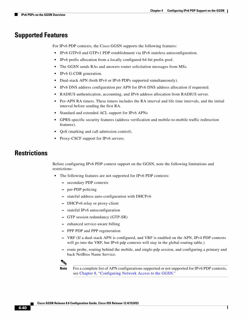
Chapter 4 Configuring IPv6 PDP Support on the GGSNIPv6 PDPs on the GGSN Overview
Supported FeaturesFor IPv6 PDP contexts, the Cisco GGSN supports the following features:
• IPv6 GTPv0 and GTPv1 PDP establishment via IPv6 stateless autoconfiguration.
• IPv6 prefix allocation from a locally configured 64-bit prefix pool.
• The GGSN sends RAs and answers router solicitation messages from MSs.
• IPv6 G-CDR generation.
• Dual-stack APN (both IPv4 or IPv6 PDPs supported simultaneously).
• IPv6 DNS address configuration per APN for IPv6 DNS address allocation if requested.
• RADIUS authentication, accounting, and IPv6 address allocation from RADIUS server.
• Per-APN RA timers. These timers includes the RA interval and life time intervals, and the initial interval before sending the first RA.
• Standard and extended ACL support for IPv6 APNs
• GPRS-specific security features (address verification and mobile-to-mobile traffic redirection features).
• QoS (marking and call admission control).
• Proxy-CSCF support for IPv6 servers.
RestrictionsBefore configuring IPv6 PDP context support on the GGSN, note the following limitations and restrictions:
• The following features are not supported for IPv6 PDP contexts:
– secondary PDP contexts
– per-PDP policing
– stateful address auto-configuration with DHCPv6
– DHCPv6 relay or proxy-client
– stateful IPv6 autoconfiguration
– GTP session redundancy (GTP-SR)
– enhanced service-aware billing
– PPP PDP and PPP regeneration
– VRF (If a dual-stack APN is configured, and VRF is enabled on the APN, IPv4 PDP contexts will go into the VRF, but IPv6 pdp contexts will stay in the global routing table.)
– route probe, routing behind the mobile, and single-pdp session, and configuring a primary and back NetBios Name Service.
Note Fro a complete list of APN configurations supported or not supported for IPv6 PDP contexts, see Chapter 8, “Configuring Network Access to the GGSN.”
4-40Cisco GGSN Release 8.0 Configuration Guide, Cisco IOS Release 12.4(15)XQ3

Chapter 4 Configuring IPv6 PDP Support on the GGSNImplementing IPv6 PDP Support on the GGSN
• IP CEF and IPv6 CEF must be enabled. (IPv6 CEF requires IP CEF to be enabled.)
• All infrastructure nodes in the PLMN (the SGSN, GGSN, and charging gateway) are assumed to be IPv4 nodes.
• IPv6 must be implemented on the supervisor engine module.
• IPv6 over IPv4 tunnels must be configured from the supervisor engine module. Tunneling from the GGSN is not supported.
• Ensure that RADIUS is implemented as an infrastructure node in the PLMN.
• Ensure that the no virtual-template snmp is configured.
• Ensure that the no virtual-template subinterface is not configured.
• Ensure that the following commands are not configured on the IPv6 base virtual template:
– snmp if-index persists
– ntp disable
Implementing IPv6 PDP Support on the GGSNTo configure IPv6 support on the GGSN, complete the tasks in the following sections:
• Enabling the Forwarding of IPv6 Traffic on the GGSN, page 4-41 (Required)
• Configuring an IPv6 Base Virtual Template Interface, page 4-42 (Required)
• Enabling IPv6 Support on the APN, page 4-44 (Required)
• Configuring a Local IPv6 Prefix Pool, page 4-46 (Required)
• Monitoring and Maintaining IPv6 PDPs, page 4-49 (Optional)
Enabling the Forwarding of IPv6 Traffic on the GGSNThe forwarding of IPv6 traffic on the GGSN requires that Cisco Express Forwarding (CEF) and IPv6 CEF are enabled globally on the GGSN. Additionally, to forward IPv6 traffic using CEF, you must also configure the forwarding of IPv6 unicast datagrams globally on the GGSN by using the ipv6 unicast-routing command.
SUMMARY STEPS
1. enable
2. configure terminal
3. ip cef
4. ipv6 unicast-routing
5. ipv6 cef
4-41Cisco GGSN Release 8.0 Configuration Guide, Cisco IOS Release 12.4(15)XQ3

Chapter 4 Configuring IPv6 PDP Support on the GGSNImplementing IPv6 PDP Support on the GGSN
DETAILED STEPS
Configuring an IPv6 Base Virtual Template InterfaceA virtual-access subinterface is created for each IPv6 PDP context established on the GGSN. The configurations for the virtual-access, such as RA timers, etc., are cloned from an IPv6 base virtual template interface that has been assigned to the APN. The commands configured under the IPv6 base virtual template define the behavior of the IPv6 protocol.
You can configure multiple base virtual templates, each with a different configuration. A base virtual template can be shared by multiple APNs, however, only one base virtual template can be assigned to an APN (using the ipv6 base-vtemplate command) at a time.
When a create PDP context request is received, a virtual sub-interface is cloned from the base virtual template that is assigned to the APN, and an IPv6 address is allocated as configured under the APN after the IPv6 virtual-access sub-interface is created. The create PDP context response is returned after the virtual-access sub-interface is created, and authentication and address allocation are successfully completed.
Caution To avoid severe performance issues, ensure that the no ipv6 nd ra suppress command is configured and that the no-virtual-template subinterface commands is not configured under the IPv6 base virtual template interface.
Command or Action Purpose
Step 1 enable
Example:Router> enable
Enables privileged EXEC mode. Enter your password if prompted.
Step 2 configure terminal
Example:Router# configure terminal
Enters global configuration mode.
Step 3 ip cef
Example:Router# configure terminal
Enables Cisco Express Forwarding for IPv4 globally on the router.
Step 4 ipv6 unicast-routing
Example:Router(config)# ipv6 unicast-routing
Enables the forwarding of IPv6 unicast datagrams.
Step 5 ipv6 cef
Example:Router(config)# ipv6 cef
Enables CEF for IPv6 globally on the router.
4-42Cisco GGSN Release 8.0 Configuration Guide, Cisco IOS Release 12.4(15)XQ3

Chapter 4 Configuring IPv6 PDP Support on the GGSNImplementing IPv6 PDP Support on the GGSN
SUMMARY STEPS
1. enable
2. configure terminal
3. interface virtual-template number
4. ipv6 enable
5. no ipv6 nd ra suppress
6. ipv6 nd ra interval {maximum-secs [minimum-secs] | msec maximum-msecs [minimum-msecs]}
7. ipv6 nd ra lifetime seconds
8. ipv6 nd ra initial [exponential] InitialAdvertInterval InitialAdvertisements
9. ipv6 nd prefix default infinite infinite off-link
10. exit
DETAILED STEPS
Command or Action Purpose
Step 1 enable
Example:Router> enable
Enables privileged EXEC mode. Enter your password if prompted.
Step 2 configure terminal
Example:Router# configure terminal
Enters global configuration mode.
Step 3 interface virtual-template number
Example:Router(config)# interface virtual-template number
Creates a virtual template interface, where number identifies the virtual template interface.
Step 4 ipv6 enable
Example:Router(config-if)# ipv6 enable
Enables IPv6 processing on an interface that has not been configured with an explicit IPv6 address.
Note This command automatically configures an IPv6 link-local unicast address on the interface while also enabling the interface for IPv6 processing.
Step 5 no ipv6 nd ra suppress
Example:Router(config-if)# no ipv6 nd ra suppress
Enables the sending of IPv6 router advertisement transmissions on non-LAN interface types (for example, serial or tunnel interfaces).
Step 6 ipv6 nd ra interval {maximum-secs [minimum-secs] | msec maximum-msecs [minimum-msecs]}
Example:Router(config-if)# ipv6 nd ra interval 21600
Configures the interval between IPv6 RA transmissions on an interface.
Step 7 ipv6 nd ra lifetime seconds
Example:Router(config-if)# ipv6 nd ra lifetime 21600
Configures the router lifetime value, in seconds, in IPv6 router advertisements on an interface.
4-43Cisco GGSN Release 8.0 Configuration Guide, Cisco IOS Release 12.4(15)XQ3
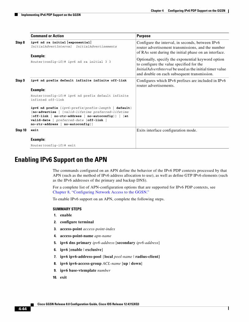
Chapter 4 Configuring IPv6 PDP Support on the GGSNImplementing IPv6 PDP Support on the GGSN
Enabling IPv6 Support on the APNThe commands configured on an APN define the behavior of the IPv6 PDP contexts processed by that APN (such as the method of IPv6 address allocation to use), as well as define GTP IPv6 elements (such as the IPv6 addresses of the primary and backup DNS).
For a complete list of APN-configuration options that are supported for IPv6 PDP contexts, see Chapter 8, “Configuring Network Access to the GGSN.”
To enable IPv6 support on an APN, complete the following steps.
SUMMARY STEPS
1. enable
2. configure terminal
3. access-point access-point-index
4. access-point-name apn-name
5. ipv6 dns primary ipv6-address [secondary ipv6-address]
6. ipv6 [enable | exclusive]
7. ipv6 ipv6-address-pool {local pool-name | radius-client}
8. ipv6 ipv6-access-group ACL-name [up | down]
9. ipv6 base-vtemplate number
10. exit
Step 8 ipv6 nd ra initial [exponential] InitialAdvertInterval InitialAdvertisements
Example:Router(config-if)# ipv6 nd ra initial 3 3
Configure the interval, in seconds, between IPv6 router advertisement transmissions, and the number of RAs sent during the initial phase on an interface.
Optionally, specify the exponential keyword option to configure the value specified for the InitialAdvertInterval be used as the initial timer value and double on each subsequent transmission.
Step 9 ipv6 nd prefix default infinite infinite off-link
Example:Router(config-if)# ipv6 nd prefix default infinite infinted off-link
ipv6 nd prefix {ipv6-prefix/prefix-length | default} [no-advertise | [valid-lifetime preferred-lifetime [off-link | no-rtr-address | no-autoconfig]] | [at valid-date | preferred-date [off-link | no-rtr-address | no-autoconfig]]
Configures which IPv6 prefixes are included in IPv6 router advertisements.
Step 10 exit
Example:Router(config-if)# exit
Exits interface configuration mode.
Command or Action Purpose
4-44Cisco GGSN Release 8.0 Configuration Guide, Cisco IOS Release 12.4(15)XQ3

Chapter 4 Configuring IPv6 PDP Support on the GGSNImplementing IPv6 PDP Support on the GGSN
DETAILED STEPS
Command or Action Purpose
Step 1 enable
Example:Router> enable
Enables privileged EXEC mode. Enter your password if prompted.
Step 2 configure terminal
Example:Router# configure terminal
Enters global configuration mode.
Step 3 access-point access-point-index
Example:Router(config)# access-point 2
Specifies an access point number and enters access-point configuration mode.
Step 4 access-point-name apn-name
Example:Router(config-access-point)# access-point-name ipv6_apn1.com
Specifies the network (or domain) name for a PDN that users can access from the GGSN at a defined access point.
Step 5 ipv6 [enable | exclusive]
Example:Router(config-access-point) ipv6 enable
Configures an access point to allow IPv6 PDP contexts.
• enable—Configures support for both IPv4 and IPv6 PDP contexts on the APN.
• exclusive—Configures support for only IPv6 PDP contexts on the APN.
By default, only IPv4 PDP contexts are supported on an APN.
Step 6 ipv6 dns primary ipv6-address [secondary ipv6-address]
Example:Router(config-access-point) ipv6 dns primary 2001:999::9
Specifies the address of a primary (and backup) IPv6 DNS to be sent in IPv6 create PDP context response if requested.
Step 7 ipv6 ipv6-address-pool {local pool-name | radius-client}
Example:Router(config-access-point) ipv6 ipv6-address-pool local localv6
Configures a dynamic IPv6 prefix allocation method for an access-point.
Note This release of the Cisco GGSN supports IPv6 prefix allocation via locally configured pools.
Step 8 ipv6 ipv6-access-group ACL-name [up | down]
Example:Router(config-access-point) ipv6 ipv6-access-group ipv6filter down
Applies an access-control list (ACL) configuration to uplink or downlink payload packets.
4-45Cisco GGSN Release 8.0 Configuration Guide, Cisco IOS Release 12.4(15)XQ3

Chapter 4 Configuring IPv6 PDP Support on the GGSNImplementing IPv6 PDP Support on the GGSN
Configuring a Local IPv6 Prefix PoolThe function of prefix pools in IPv6 is similar to that of address pools in IPv4. The main difference is that IPv6 assigns prefixes rather than single addresses.
As for IPv4, an IP address can be obtained from a locally-configured pool, or it can be retrieved from an AAA server. The Cisco GGSN supports prefix allocation via local pools.
When configuring a local IPv6 prefix pool, note that overlapping membership between pools is not permitted. Once a pool is configured, it cannot be changed. If you change the pool configuration, the pool is removed and re-created and all prefixes previously allocated will be freed.
For detailed information on configuring local IPv6 prefix pools using the following commands, refer to the Cisco IOS IPv6 Configuration Guide.
SUMMARY STEPS
1. enable
2. configure terminal
3. ipv6 local pool poolname prefix/prefix-length assigned-length [shared] [cache-size size]
4. exit
DETAILED STEPS
Step 9 ipv6 base-vtemplate number
Example:Router(config-access-point) ipv6 base-vtemplate 10
Specifies the base virtual template interface from which the APN copies IPv6 RA parameters when creating virtual sub-interfaces for IPv6 PDP contexts.
Step 10 exit
Example:Router(config-access-point)# exit
Exits interface configuration mode.
Command or Action Purpose
Command or Action Purpose
Step 1 enable
Example:Router> enable
Enables privileged EXEC mode. Enter your password if prompted.
Step 2 configure terminal
Example:Router# configure terminal
Enters global configuration mode.
4-46Cisco GGSN Release 8.0 Configuration Guide, Cisco IOS Release 12.4(15)XQ3

Chapter 4 Configuring IPv6 PDP Support on the GGSNImplementing IPv6 PDP Support on the GGSN
Configuring an IPv6 Access Control ListIPv6 access control lists restrict IPv6-related traffic based on the configured IPv6 filters. A filter contains the rules to match an IP packet, and if the packet matches, the rule also stipulates if the packet should be permitted or denied.
An IPv6 access control filter is applied to a APN using the ipv6 ipv6-access-group access-point configuration command.
For detailed information on configuring IPv6 Access Control Lists using the following commands, refer to the Cisco IOS IPv6 Configuration Guide.
SUMMARY STEPS
1. enable
2. configure terminal
3. ipv6 access-list access-list-name
4. deny protocol {source-ipv6-prefix/prefix-length | any | host source-ipv6-address} [operator [port-number]] {destination-ipv6-prefix/prefix-length | any | host destination-ipv6-address} [operator [port-number]] [dest-option-type [doh-number | doh-type]] [dscp value] [flow-label value] [fragments] [log] [log-input] [mobility] [mobility-type [mh-number | mh-type]] [routing] [routing-type routing-number] [sequence value] [time-range name] [undetermined-transport]
5. permit protocol {source-ipv6-prefix/prefix-length | any | host source-ipv6-address} [operator [port-number]] {destination-ipv6-prefix/prefix-length | any | host destination-ipv6-address} [operator [port-number]] [dest-option-type [doh-number | doh-type]] [dscp value] [flow-label value] [fragments] [log] [log-input] [mobility] [mobility-type [mh-number | mh-type]] [reflect name [timeout value]] [routing] [routing-type routing-number] [sequence value] [time-range name]
6. exit
Step 3 ipv6 local pool poolname prefix/prefix-length assigned-length [shared] [cache-size size]
Example:Router(config)# ipv6 local pool pool1 2001:0DB8::/48 64
Router# show ipv6 local pool
Pool Prefix Free In use
pool1 2001:0DB8::/48 65516 20
Configures a local IPv6 prefix pool.
Note The value 64 must be configured as the assigned length. The minimum prefix length accepted by the GGSN is /48.
Step 4 exit
Example:Router(config)# exit
Exits interface configuration mode.
Command or Action Purpose
4-47Cisco GGSN Release 8.0 Configuration Guide, Cisco IOS Release 12.4(15)XQ3

Chapter 4 Configuring IPv6 PDP Support on the GGSNImplementing IPv6 PDP Support on the GGSN
DETAILED STEPS
Command or Action Purpose
Step 1 enable
Example:Router> enable
Enables privileged EXEC mode. Enter your password if prompted.
Step 2 configure terminal
Example:Router# configure terminal
Enters global configuration mode.
Step 3 ipv6 access-list access-list-name
Example:Router(config)# ipv6 access-list ipv6filter
Defines an IPv6 access list name and places the GGSN in IPv6 access list configuration mode.
Step 4 deny protocol {source-ipv6-prefix/prefix-length | any | host source-ipv6-address} [operator [port-number]] {destination-ipv6-prefix/prefix-length | any | host destination-ipv6-address} [operator [port-number]] [dest-option-type [doh-number | doh-type]] [dscp value] [flow-label value] [fragments] [log] [log-input] [mobility] [mobility-type [mh-number | mh-type]] [routing] [routing-type routing-number] [sequence value] [time-range name] [undetermined-transport]
Example:Router(config-ipv6-acl)# deny ipv6 any 2001:200::/64
Sets deny conditions for an IPv6 access list.
Step 5 permit protocol {source-ipv6-prefix/prefix-length | any | host source-ipv6-address} [operator [port-number]] {destination-ipv6-prefix/prefix-length | any | host destination-ipv6-address} [operator [port-number]] [dest-option-type [doh-number | doh-type]] [dscp value] [flow-label value] [fragments] [log] [log-input] [mobility] [mobility-type [mh-number | mh-type]] [reflect name [timeout value]] [routing] [routing-type routing-number] [sequence value] [time-range name]
Example:Router(config-ipv6-acl)# permit ipv6 any any
Sets permit conditions for an IPv6 access list.
Step 6 exit
Example:Router(config)# exit
Exits interface configuration mode.
4-48Cisco GGSN Release 8.0 Configuration Guide, Cisco IOS Release 12.4(15)XQ3

Chapter 4 Configuring IPv6 PDP Support on the GGSNImplementing IPv6 PDP Support on the GGSN
Configuring Additional IPv6 Support Options on the GGSNThis section summarizes some other IPv6-specific options that you can configure on an access-point.
Additional details about configuring several of these options are discussed in other chapters of this book. Note that these options apply to IPv6 PDP contexts only. A summary of all APN options that can be configured are described in Chapter 8, “Configuring Network Access to the GGSN.”
To configure additional IPv6-specific options for a GGSN access point, use any of the following commands, beginning in access- point list configuration mode:
Monitoring and Maintaining IPv6 PDPsThe following privilege EXEC show commands can be used to monitor the IPv6 configuration and IPv6 PDPs on the GGSN.
Command Purpose
Step 7 Router(config-access-point)# ipv6 ipv6-access-group ACL-name [up | down]
(Optional) Applies an access-control list (ACL) configuration to uplink or downlink payload packets.
Step 8 Router(config-access-point)# ipv6 redirect [all | intermobile] ipv6-address
(Optional) Configures the GGSN to redirects IPv6 traffic to an external IPv6 device. The available options are:
• all—Redirects all IPv6 traffic to an external IPv6 device for an APN.
• intermobile—Redirects mobile-to-mobile IPv6 traffic to an external IPv6 device.
• ipv6-address—IP address of the IPv6 external device to which you want to redirect IPv6 traffic.
Step 9 Router(config-access-point)# ipv6 security verify source
(Optional) Enables the GGSN to verify the IPv6 source address of an upstream TPDU against the address previously assigned to an MS.
Command PurposeRouter# show gprs access-point Displays information about access points on the GGSN.
Router# show gprs access-point statistics Displays data volume and PDP activation and deactivation statistics for access point on the GGSN.
Router# show gprs access-point status Displays the number of active PDPs on an access point and how many of those PDPs are IPv4 PDPs an dhow many are IPv6 PDPs.
Router# show gprs gtp pdp-context Displays a list of the currently active PDP contexts.
Router# show gprs gtp status Displays information about the current status of the GTP on the GGSN.
Router# show gprs pcscf Displays a summary of the P-CSCF server group(s) configured on the GGSN for P-CSCF Discovery.
4-49Cisco GGSN Release 8.0 Configuration Guide, Cisco IOS Release 12.4(15)XQ3

Chapter 4 Configuring IPv6 PDP Support on the GGSNConfiguration Example
Configuration ExampleThe following example shows IPv6 support configured on a GGSN. The IPv6 related configuration statements appear in bold text:
ip cef!ipv6 unicast-routingipv6 cef!interface Virtual-Template10 ipv6 enable no ipv6 nd ra suppress ipv6 nd ra interval 21600 ipv6 nd ra lifetime 21600 ipv6 nd ra initial 3 3 ipv6 nd prefix default infinite infinite off-link!access-point 2 access-point-name ipv6_test.com ipv6 dns primary 2001:999::9 ipv6 enable ipv6 ipv6-address-pool local localv6 ipv6 base-vtemplate 10!ipv6 local pool localv6 2001:234::/48 64!!
4-50Cisco GGSN Release 8.0 Configuration Guide, Cisco IOS Release 12.4(15)XQ3

Cisco GGSN Release 8.0
C H A P T E R5
Configuring GGSN GTP Session RedundancyThis chapter describes how to configure GTP session redundancy (GTP-SR) between two GGSNs.
Note The Cisco GGSN supports GTP Session Redundancy for IPv4 PDP contexts only.
For a complete description of the GGSN commands in this chapter, refer to the Cisco GGSN Command Reference for the Cisco GGSN release you are using.
To locate documentation of other commands that appear in this chapter, use the command reference master index or search online. See the “Related Documents” section on page 2-10 for a list of the other Cisco IOS software documentation that might be helpful while configuring the GGSN.
This chapter includes the following sections:
• GTP Session Redundancy Overview, page 5-1
• Enabling GTP Session Redundancy, page 5-4
• Disabling GTP Session Redundancy, page 5-9
• Configuring Charging-Related Synchronization Parameters, page 5-10
• Monitoring and Maintaining GTP-SR, page 5-12
• Upgrading GGSN Images in a GTP-SR Environment, page 5-12
• Configuration Examples, page 5-12
GTP Session Redundancy Overview Cisco GGSN Release 5.1 and later supports Active/Standby, 1-to-1 inter-device GTP session redundancy (GTP-SR). GTP-SR enables two GGSNs located on separate Cisco Service and Application Module for IP (SAMI) installed in separate Cisco 7600 series router chassis to appear as one network entity and ensures that continuous service is provided to mobile subscribers in the event one of the GGSNs fails.
The Cisco IOS GGSN software uses the Cisco IOS Hot Standby Routing Protocol (HSRP), the Cisco IOS Check-point Facility (CF) and Redundancy Framework (CF), and Stream Control Transmission Protocol (SCTP) to provide inter-device redundancy and high availability.
5-1Configuration Guide, Cisco IOS Release 12.4(15)XQ3

Chapter 5 Configuring GGSN GTP Session RedundancyGTP Session Redundancy Overview
In a GTP-SR implementation, the Active GGSN establishes and terminates PDP sessions and sends required stateful data to the Standby GGSN. To stay current on the states of active PDP sessions, the Standby GGSN receives the stateful data sent by the Active GGSN. As soon as the Standby GGSN detects that the Active GGSN has failed, it becomes active and assumes the responsibilities of the Active GGSN.
Figure 5-1 illustrates a GTP-SR implementation.
Figure 5-1 GTP-SR Configuration
Note Before GTP-SR can be enabled on the redundant GGSNs, a GTP-SR inter-device infrastructure must be configured. For information on configuring the GTP-SR inter-device infrastructure, see the “Configuring the GTP Session Redundancy Inter-Device Infrastructure” section on page 5-4
PrerequisitesProper GTP-SR operation requires the following:
• Two Cisco 7600 series router in which a Cisco Supervisor Engine 720 (Sup720), with a Multilayer Switch Feature Card (Cisco Product ID: SUP720-MSFC3-BXL), running Cisco IOS Release 12.2(33)SRB1 or later is installed.
• Two Cisco SAMIs in each of the Cisco 7600 series routers. The SAMI processors must be running the same Cisco IOS GGSN software release, Cisco IOS Release 12.4(15)XQ or later.
• HSRP Version 2.
• The Active and Standby GGSNs have the same configuration, except for certain protocol-related configurations that need to be distinct such as the IP addresses of the HSRP-enabled interfaces and the remote IP addresses in the SCTP configuration.
Each of the configurations must be completed in the same order on both of the units of the GTP-SR configuration.
RAN
Internet
PLMN IPnetwork
Corporateintranet
Gn
GGSN-A
1291
01
GGSN-B
GGSN: GTP-SR system
Ga
Gi
AAA CGDHCP
RADIUS
5-2Cisco GGSN Release 8.0 Configuration Guide, Cisco IOS Release 12.4(15)XQ3

Chapter 5 Configuring GGSN GTP Session RedundancyGTP Session Redundancy Overview
• When loading or upgrading a new Cisco GGSN image, both GGSNs must be loaded (virtually) together.
• On the SGSN, the values configured for the number GTP N3 requests and T3 retransmissions are larger than the switchover timer. This enables requests sent during a switchover to be serviced by the newly Active GGSN rather than dropped.
• RADIUS has been forced to use the IP address of a specified interface for all outgoing RADIUS packets using the ip radius source-interface global configuration command.
Limitations and RestrictionsBefore configuring GTP-SR, note the following limitations and restrictions:
• PDP Contexts —Redundancy is not supported for the following types of PDP contexts. In the case of a switchover, these PDP contexts require re-establishment on the Standby GGSN once it becomes active.
– PPP type PDP
– PPP Regeneration / L2TP access
– Network Initiated
• Timers—Except for the session timer, GGSN timers are not synchronized to the Standby GGSN. When a switchover occurs, the timers on the newly Active GGSN are restarted with an increment to prevent many of them from expiring simultaneously.
When a PDP context is recreated on the Standby GGSN, the session timer is restarted with the elapsed time subtracted from the initial session timer value. Once the session expires on the Standby GGSN, the PDP context is deleted.
• Counters—When a change from a Standby to an Active GGSN occurs, all counters are set back to zero. However, this statement is incorrect.
Note that if a switchover occurs, status counters, such as "cgprsAccPtSuccMsActivatedPdps," and some statistics counters will have a non-zero value that is the value of the counter at the time the switchover occurred. All other counters will be reset to zero.
If a GGSN reload occurs, all counters are set back to zero.
• Sequence numbers related to GTP signaling and data are not synchronized between the Active and Standby GGSNs.
• Charging—All pertinent information to establish charging on the Standby GGSN for a PDP context is synchronized, however, the user data related charging information for a PDP context is not. Therefore all CDRs in the previously Active GGSN that were not sent to the charging gateway are lost when a switchover occurs.
• Once a GTP-SR relationship is formed between two GGSNs, modifying the configuration of a GGSN might cause the GGSN to reload before the changes can be saved. To ensure that this does not occur, disable GTP-SR before modifying the configuration of a GGSN. For information on disabling GTP-SR, see “Disabling GTP Session Redundancy” section on page 5-9.
• In a GTP session redundancy (GTP-SR) environment, do not use the clear gprs gtp pdp-context command on the Standby GGSN. If you issue this command on the Standby GGSN, you are prompted to confirm before the command is processed. To confirm the state of a GGSN, issue the show gprs redundancy command.
5-3Cisco GGSN Release 8.0 Configuration Guide, Cisco IOS Release 12.4(15)XQ3

Chapter 5 Configuring GGSN GTP Session RedundancyEnabling GTP Session Redundancy
Enabling GTP Session RedundancyTo configure GTP-SR, complete the tasks, in the order in which they are presented, in the following sections:
• Configuring the GTP Session Redundancy Inter-Device Infrastructure, page 5-4
• Configuring GTP-SR on the GGSN, page 5-9
• Configuring Charging-Related Synchronization Parameters, page 5-10
Configuring the GTP Session Redundancy Inter-Device InfrastructureThe GGSN GTP-SR feature uses the Cisco IOS Check-point Facility (CF) to send stateful data over Stream Control Transmission Protocol (SCTP) to a redundant GGSN. Additionally, in conjunction with Cisco IOS HSRP, the GGSN uses the Cisco IOS Redundancy Facility (RF) to monitor and report transitions on Active and Standby GGSNs.
To configure the GTP-SR inter-device infrastructure before enabling GTP-SR on the redundant GGSNs, complete the tasks in the following sections
• Configuring HSRP, page 5-4
• Enabling Inter-Device Redundancy, page 5-6
• Configuring the Inter-Device Communication Transport, page 5-7
Configuring HSRP
The Hot Standby Router Protocol (HSRP) provides high network availability because it routes IP traffic from hosts on networks without relying on the availability of any single router. HSRP is used in a group of routers for selecting an Active router and a Standby router. HSRP monitors both the inside and outside interfaces so that if any interface goes down, the whole device is deemed to be down and the Standby device becomes active and takes over the responsibilities of an Active device.
Restrictions and Recommendations
When configuring HSRP, note that the following recommendation and restrictions apply:
• At minimum, HSRP must be enabled and an HSRP primary group defined on one interface per GGSN instance. Each additional HRSP interface on the GGSN, with its own separate VLAN, can be configured as a follow group using the standby interface configuration command with the follow keyword option specified with the same group number as the primary group.
The follow group feature enables all interfaces configured with an HRSP follow group to share the HSRP parameters of the primary group. This facilitate HRSP group setup and maintenance in environments that contain a large number of GGSN interfaces and HRSP groups. The primary group and associated follow groups share the same group track states together and have the same priority.
Typically, HRSP groups are needed on the following interfaces. One group is configured as the primary group and the rest as follow groups. Each interface must be configured on different VLANs.
– Gn interface—primary group
– Ga interface—follow group
– DHCP (can be shared with the Gi interface)—follow group
– Gi APN (per VRF)—follow group
5-4Cisco GGSN Release 8.0 Configuration Guide, Cisco IOS Release 12.4(15)XQ3

Chapter 5 Configuring GGSN GTP Session RedundancyEnabling GTP Session Redundancy
• The same HSRP group cannot be used on another Active/Standby GGSN pair mapped to the same physical VLAN.
• When HRSP is configured on an interface, a preemption delay can be configured using the standby preempt interface configuration command. However, in a GTP-SR environment, we recommend that you do not configure a preemption delay unless absolutely necessary. This prevents any unnecessary switchovers. If a preemption delay must be configure, ensure that a sufficient delay is specified so that bulk synchronization can complete before preemption takes affect.
• When the standby use-bia command is not used to allow bridge and gateways to learn the virtual MAC address, for optimization purposes, configure the standby mac-refresh command to a value greater than the default (hello messages are sent every 10 seconds) under the main interface (gig0/0). Once configured, all HSRP groups (primary and follow) will send Hello messages only if the node is in Active mode.
• Use the same group number for each GGSN follow group as is defined for the primary group. Using the same group number for the primary and follow groups facilitates HRSP group setup and maintenance in an environment that contains a large number of GGSN interfaces and HRSP groups.
Note A GGSN will reload if additional HSRP configurations are added after the initial HSRP setup has been configured.
For complete information on configuring Cisco IOS HSRP, see “Configuring the Hot Standby Router Protocol” section of the Cisco IOS IP Configuration Guide, Release 12.3.
Enabling HSRP and Configuring an HSRP Primary Group
To enable HSRP on an interface and configure the primary group, use the following commands in interface configuration mode:
Command Purpose
Step 1 Router(config-if)# standby version 2 Changes the HSRP version to HSRP Version 2.
Step 2 Router(config-if)# standby [group-number] ip [ip-address [secondary]]
Enables the HSRP on the interface.
Step 3 Router(config-if)# standby [group-number] priority priority
Set the Hot Standby priority used in choosing the active router. The priority value range is from 1 to 255, where 1 denotes the lowest priority and 255 denotes the highest priority. Specify that, if the local router has priority over the current active router, the local router should attempt to take its place as the active router.
Step 4 Router(config-if)# standby [group-number] name name Specifies the name of the standby group.
Step 5 Router(config-if)# standby use-bia [scope interface] (Optional) Configures HSRP to use the burned-in address of an interface as its virtual MAC address instead of the preassigned MAC address.
5-5Cisco GGSN Release 8.0 Configuration Guide, Cisco IOS Release 12.4(15)XQ3

Chapter 5 Configuring GGSN GTP Session RedundancyEnabling GTP Session Redundancy
Configuring HSRP Follow Groups
Once HSRP has been enabled and the primary group configured on a GGSN interface, additional GGSN interfaces can be configured to share the HSRP parameters of the primary group by configuring it as a HRSP follow group on the interface using the standby interface configuration command with the follow keyword option specified with the same group number as the primary group. Interfaces that share a group track states together and have the same priority.
Note HSRP group parameters such as priority, name, tracking, and timers are configured under the primary group only. Do not configure these parameters under follow groups because they inherit them from the primary group.
To configure an interface to follow a primary group, use the following command in interface configuration mode:
Enabling Inter-Device Redundancy
The HRSP primary group is associated with Cisco IOS Redundancy Facility (RF) to enable session redundancy between two GGSNs.
To enable inter-device redundancy, use the following commands beginning in global configuration mode.
Command Purpose
Step 1 Router(config-if)# standby group-number follow group-name
Specifies the number of the follow group and the name of the primary group to follow and share status.
Note The group number specified must be the same as the primary group number.
Step 1 Router(config-if)# standby group-number ip virtual-ip-address
Specifies the group number and virtual IP address of the follow group.
Note The group number specified must be the same as the primary group number.
Command Purpose
Step 1 Router(config)# redundancy inter-device Configures redundancy and enters inter-device configuration mode.
To remove all inter-device configuration, use the no form of the command.
Step 2 Router(config-red-interdevice)# scheme standby standby-group-name
Defines the redundancy scheme that is to be used. Currently, “standby” is the only supported scheme.
• standby-group-name—Must match the standby name specified in the standby name interface configuration command (see the “Configuring HSRP” section on page 5-4). Also, the standby name should be the same on both GGSNs.
Step 3 Router(config-red-interdevice)# exit Returns to global configuration mode.
5-6Cisco GGSN Release 8.0 Configuration Guide, Cisco IOS Release 12.4(15)XQ3

Chapter 5 Configuring GGSN GTP Session RedundancyEnabling GTP Session Redundancy
Configuring the Inter-Device Communication Transport
Inter-device redundancy requires a transport for communication between the redundant GGSNs. This transport is configured using Interprocess Communication (IPC) commands.
To configure the inter-device communication transport between the two GGSNs, use the following commands beginning in global configuration mode:
Command Purpose
Step 1 Router(config)# ipc zone default Configures the Inter-device Communication Protocol (IPC) and enters IPC zone configuration mode.
Use this command to initiate the communication link between the Active device and the Standby device.
Step 2 Router(config-ipczone)# association 1 Configures an association between two devices and enters IPC association configuration mode.
In IPC association configuration mode, you configure the details of the association, such as the transport protocol, local port and local IP addresses, and the remote port and remote IP addresses.
Valid association IDs range from 1 to 255. There is no default value.
Step 3 Router(config-ipczone)# no shutdown Restarts a disabled association and its associated transport protocol.
Note Shutdown of the association is required for any changes to the transport protocol parameters.
Step 4 Router(config-ipczone-assoc)# protocol sctp Configures Stream Control Transmission Protocol (SCTP) as the transport protocol for this association and enables SCTP protocol configuration mode.
Step 5 Router(config-ipc-protocol-sctp)# local-port local_port_num
Defines the local SCTP port number to use to communicate with the redundant peer and enables IPC Transport-SCTP local configuration mode.
Valid port numbers range from 1 to 65535. There is no default value.
Note The local port number should be the same as the remote port number on the peer router.
Step 6 Router(config-ipc-local-sctp)# local ip ip_addr Defines the local IP address that is used to communicate with the redundant peer. The local IP address must match the remote IP address on the peer router.
5-7Cisco GGSN Release 8.0 Configuration Guide, Cisco IOS Release 12.4(15)XQ3

Chapter 5 Configuring GGSN GTP Session RedundancyEnabling GTP Session Redundancy
To remove an association, use the no form of the command.
Step 7 Router(config-ipc-local-sctp)# keepalive [period [retries]]
Enables keepalive packets and specifies the number of times that the Cisco IOS software tries to send keepalive packets with a response before bringing down the interface or tunnel protocol for a specific interface.
Valid value for period is an integer value in seconds great than 0. The default is 10. Valid value for retries is an integer value greater than one and less than 355. The default is the previously used value or 5 if there was no value previously specified.
Step 8 Router(config-ipc-local-sctp)# retransmit-timeout interval
Configures the message retransmission time.
Valid range is 300 to 60000 milliseconds. The default is minimum 300/maximum 600.
Step 9 Router(config-ipc-local-sctp)# path-retransmit number
Configures the maximum number of keep-alive retries before the corresponding destination address is marked inactive.
Valid range is 2 to 10. The default is 4.
Step 10 Router(config-ipc-local-sctp)# assoc-retransmit number
Defines the maximum number of retransmissions over all destination addresses before an association is declared failed.
Valid range is 2 to 20. The default is 4.
Step 11 Router(config-ipc-local-sctp)# max-inbound-streams max-streams
Configures the maximum number of inbound streams allowed for the local port.
Valid range is 2 to 25. The default is 17 streams.
Step 12 Router(config-ipc-local-sctp)# init-timeout msec Configures the maximum interval for the init packet retransmission time-out value.
Valid range is 1000 to 60000 milliseconds. The default is 1000 milliseconds.
Step 13 Router(config-ipc-local-sctp)# exit Exits IPC transport - SCTP local configuration mode.
Step 14 Router(config-ipc-protocol-sctp)# remote-port port_nun
Defines the remote SCTP port that is used to communicate with the redundant peer and enables IPC Transport-SCTP remote configuration mode.
Valid port numbers range from 1 to 65535. There is no default.
Note The remote port number should be the same as the local port number on the peer device.
Step 15 Router(config-ipc-remote-sctp)# remote-ip ip_addr Defines the remote IP address of the redundant peer that is used to communicate with the local device. All remote IP addresses must refer to the same device.
Command Purpose
5-8Cisco GGSN Release 8.0 Configuration Guide, Cisco IOS Release 12.4(15)XQ3

Chapter 5 Configuring GGSN GTP Session RedundancyDisabling GTP Session Redundancy
Configuring GTP-SR on the GGSNTo enable GTP-SR on a GGSN, use the following command in global configuration mode on both GGSNs of a redundant pair:
Disabling GTP Session RedundancyTo disable GTP-SR (at both the application level and inter-device infrastructure level), complete the following tasks in the following example in the order in which they are listed. Ensure the GGSN is in Standby mode when you start these tasks.
1. Verify the GGSN is in standby mode and disable the GGSN application-level redundancy.
Router(config)# show gprs redundancy...Router(config)# no gprs redundancy
The GGSN becomes a standalone active GGSN.
2. Remove the standby scheme configured under inter-device configuration mode.
Router(config)# redundancy inter-deviceRouter(config-red-interdevice)# no scheme standby HSRP-Gn
3. Save configuration changes to memory.
Router(config)# write memory
4. Reload the router.
Router# reload
Once the GGSN comes back up, additional configuration changes can be made and saved without the GGSN reloading.
5. Disable SCTP by disabling the association between the two devices and deconfiguring SCTP.
Router(config)# ip zone defaultRouter(config-ipczone)# association 1Router(config-ipczone-assoc)# shutdown...Router(config-ipczone-assoc)# no protocol sctp
Command Purpose
Router(config)# gprs redundancy Enables GTP-SR on a GGSN.
5-9Cisco GGSN Release 8.0 Configuration Guide, Cisco IOS Release 12.4(15)XQ3

Chapter 5 Configuring GGSN GTP Session RedundancyConfiguring Charging-Related Synchronization Parameters
6. To remove the HRSP configuration associated with an interface, use the no forms of the relevant HSRP commands. Remove the HRSP group configuration for the follow groups first.
Router(config)# interface GigabitEthernet0/0.56001Router(config-if)# no standby 52 ip 172.90.1.52Router(config-if)# no standby 52 follow HSRP-GnRouter(config-if)# no standby version 2Router(config-if)# exit
Router(config)# interface GigabitEthernet0/0.401Router(config-if)# no standby 52 ip 192.1268.1.52Router(config-if)# no standby 52 name HSRP-GnRouter(config-if)# no standby version 2Router(config-if)# exit
7. Save configuration changes to memory:
Router(config)# write memory
Configuring Charging-Related Synchronization ParametersCharging-related data necessary to establish charging for a PDP context is synchronized to the Standby GGSN. This data includes:
– Charging Identity (CID) associated with a PDP context
– Local sequence number
– Record sequence number
– GTP’ sequence number
Charging Identity (CID) and Local Record Sequence Number
When an established PDP context is synchronized, the CID assigned to the PDP context’s CDR is also synchronized to the Standby GGSN. When the Standby GGSN receives the synchronized data for the PDP context, if the CID value provided is greater than the current value of the global CID counter, it writes the value to the global CID counter. If a switchover occurs, the newly Active GGSN starts from the latest CID value that was written, plus a window/offset for all new PDP contexts created on the newly Active GGSN.
When the Active GGSN’s CID timer expires and it writes the global CID counter value to memory, the CID value and local record sequence (if configured) are synchronized to the Standby GGSN, which writes the information to its memory. If the local sequence number is also configured, when the write timer associated with the local sequence number expires, both the CID and the local sequence number are synchronized to the Standby GGSN. When the unit becomes active, it will use the local record sequence number, plus the latest CID value written to memory, plus a window/offset for subsequent PDP contexts created on the newly Active GGSN.
Record Sequence Number
The record sequence number is used by the charging gateway to detect duplicate CDRs associated with a PDP context.
To minimize the amount of data being synchronized to the Standby GGSN, the record sequence number is not synchronized each time a CDR is closed. Instead, a window threshold for the record sequence number is synchronized each time a CDR closes. The current value of the record sequence number and the record number last synchronized for a PDP context is checked. If the difference is the value
5-10Cisco GGSN Release 8.0 Configuration Guide, Cisco IOS Release 12.4(15)XQ3

Chapter 5 Configuring GGSN GTP Session RedundancyConfiguring Charging-Related Synchronization Parameters
configured for the window size (using the gprs redundancy charging sync-window cdr rec-seqnum global configuration command), the current record sequence number is synchronized to the Standby GGSN.
When a Standby GGSN becomes the Active GGSN, it starts from the last value synchronized plus the window size.
To configure the window size used to determine when the CDR record sequence number needs to be synchronized to the Standby GGSN, use the following command in global configuration mode:
GTP’ Sequence Number
The GTP’ sequence number is used by the charging gateway to prevent the duplication of packets. The GGSN sends encoded CDRs associated with a PDP context in a GTP packet to the charging gateway. If the GTP packet is acknowledged by the charging gateway, it removes the packet from memory. If it is not acknowledged, it is retransmitted. The charging gateway cannot acknowledged GTP packets if the sequence number repeats.
To minimize the amount of data being synchronized to the Standby GGSN, the GTP’ sequence number is not synchronized each time a CDR is closed. Instead, a window threshold for the GTP’ sequence number is synchronized each time a CDR message is sent. The current value of the GTP’ sequence number and the gtpp sequence number last synchronized for a PDP context is checked and if the difference is the value configured for the window size (using the gprs redundancy charging sync-window gtpp seqnum global configuration command), the GTP prime sequence number is synchronized to the Standby GGSN.
When a Standby GGSN becomes the Active GGSN, it starts from the last value synchronized plus the window size.
To configure the window size used to determine when the GTP’ sequence number needs to be synchronized to the Standby GGSN, use the following command in global configuration mode:
Command Purpose
Router# gprs redundancy charging sync-window cdr rec-seqnum size
Configures the window size used to determine when the CDR record sequence number needs to be synchronized. Valid range is 1 to 20. The default is 10.
Command PurposeRouter# gprs redundancy charging sync-window gtpp seqnum size
Configures the window size used to determine when the GTP’ sequence number needs to be synchronized. Valid range is 5 to 65535. The default is 10000.
Note Since a GGSN can transmit 128 GTP packets without any acknowledgement, we recommend that you configure the window size to be greater than 128.
5-11Cisco GGSN Release 8.0 Configuration Guide, Cisco IOS Release 12.4(15)XQ3

Chapter 5 Configuring GGSN GTP Session RedundancyMonitoring and Maintaining GTP-SR
Monitoring and Maintaining GTP-SRThe following privilege EXEC show commands can be used to monitor the different aspects of the GTP-SR configuration on the GGSN.
Upgrading GGSN Images in a GTP-SR EnvironmentTo upgrade to an new GGSN image on the SAMI, the following tasks must be completed.
1. Identify all application entities (GGSN images) on the SAMI using the show version processor command.
2. Remove all GGSNs belonging to the SAMI from the GTP SLB list on the supervisor, using the Cisco IOS SLB no inservice command. This prevent a GGSN from receiving new create PDP context requests, but it continues to service existing PDP contexts.
3. Wait until all PDP contexts are cleared, or if desired, manually clear established PDP contexts using the clear gprs gtp pdp-context command.
4. Load the new images onto the SAMI and reset the SAMI as described in the Cisco Service and Application Module for IP User Guide.
5. Once the images have been reloaded, return the GGSNs to the GTP SLB list by using the Cisco IOS SLB inservice command on the supervisor.
For complete information on upgrading application images on the Cisco SAMI, see the Cisco Service and Application Module for IP User Guide.
Configuration ExamplesThis section provides examples of the of the following examples:
• Primary Supervisor Configuration Example, page 5-13
• Primary GGSN Configuration Example, page 5-16
• Secondary GGSN Configuration Example, page 5-17
Note The following configurations examples are just samples of configurations. Actual configurations vary based on network design.
Command Purpose
Router# show gprs redundancy Displays statistics related to GTP-SR.
Router# show redundancy [clients | counters | events | history | states | switchovers]
Displays current or historical status and related information on planned or logged handovers.
Router# show standby Displays HSRP information.
5-12Cisco GGSN Release 8.0 Configuration Guide, Cisco IOS Release 12.4(15)XQ3

Chapter 5 Configuring GGSN GTP Session RedundancyConfiguration Examples
Primary Supervisor Configuration ExampleThe following configuration example shows part of a sample configuration on the Primary Supervisor with some of the commands that you use to configure GTP-SR highlighted in bold text:
sup-primary#show running-config Building configuration...
Current configuration : 7144 bytes!! Last configuration change at 12:28:26 UTC Tue Oct 21 2003! NVRAM config last updated at 13:32:08 UTC Thu Oct 16 2003!version 12.2service timestamps debug uptimeservice timestamps log uptimeno service password-encryption!hostname sup-primary!...!svclc multiple-vlan-interfaces svclc module 7 vlan-group 71,73 svclc vlan-group 71 71 svclc vlan-group 73 95,100,101ip subnet-zero!!no ip domain-lookup!!ip slb probe PING-PROBE ping interval 3 faildetect 5!ip slb serverfarm GGSN-SR-FARM probe PING-PROBE ! real 10.20.30.11 weight 4 reassign 4 faildetect numconns 1 numclients 1 no inservice ! real 10.20.30.12 weight 4 reassign 4 faildetect numconns 1 numclients 1 inservice ! real 10.20.30.13 weight 4 reassign 4 faildetect numconns 1 numclients 1 no inservice ! real 10.20.30.14 weight 1 faildetect numconns 1 numclients 1 no inservice ! real 10.20.30.15 weight 1
5-13Cisco GGSN Release 8.0 Configuration Guide, Cisco IOS Release 12.4(15)XQ3

Chapter 5 Configuring GGSN GTP Session RedundancyConfiguration Examples
faildetect numconns 1 numclients 1 no inservice!ip slb vserver VIRTUAL-GGSN-V0 virtual 10.20.30.91 udp 3386 service gtp serverfarm GGSN-SR-FARM idle gtp request 180 inservice!ip slb vserver VIRTUAL-GGSN-V1 virtual 10.20.30.91 udp 2123 service gtp serverfarm GGSN-SR-FARM idle gtp request 180 inservice!mpls ldp logging neighbor-changesmls flow ip destinationmls flow ipx destination!spanning-tree extend system-id!redundancy mode rpr-plus main-cpu auto-sync running-config auto-sync standard!interface GigabitEthernet2/1 description "VLAN for Inter-dev SCTP" no ip address switchport switchport access vlan 498 switchport mode access no cdp enable!...!interface FastEthernet3/25 description "VLAN for Gn" no ip address duplex full switchport switchport access vlan 410 switchport mode access no cdp enable!interface FastEthernet3/26 description "VLAN for Gi" no ip address duplex full switchport switchport access vlan 420 switchport mode access!...!interface Vlan1 no ip address shutdown!interface Vlan410 description "Virtual LAN for Gn interface for all GGSNs on an SAMI" ip address 10.20.21.1 255.255.255.0 no ip redirects
5-14Cisco GGSN Release 8.0 Configuration Guide, Cisco IOS Release 12.4(15)XQ3

Chapter 5 Configuring GGSN GTP Session RedundancyConfiguration Examples
!interface Vlan420 description "One Gi Vlan all GGSN images of mwmam" ip address 10.20.51.1 255.255.255.0 no ip redirects!interface Vlan498 description "VLAN for Inter-dev_SCTP" ip address 10.70.71.1 255.255.255.0!router ospf 1 router-id 10.20.1.2 log-adjacency-changes summary-address 10.20.30.0 255.255.255.0 redistribute static subnets route-map GGSN-routes network 10.20.1.0 0.0.0.255 area 1!ip classlessip route 0.0.0.0 0.0.0.0 128.107.234.100ip route 1.8.0.0 255.255.0.0 1.8.0.1ip route 1.12.0.0 255.255.0.0 1.12.0.1ip route 10.2.5.0 255.255.255.0 10.2.15.1ip route 10.20.30.11 255.255.255.255 10.20.21.81ip route 10.20.30.12 255.255.255.255 10.20.21.82ip route 10.20.30.13 255.255.255.255 10.20.21.83ip route 10.20.30.14 255.255.255.255 10.20.21.84ip route 10.20.30.15 255.255.255.255 10.20.21.85ip route 110.1.0.0 255.255.0.0 10.20.51.91ip route 120.1.0.0 255.255.0.0 10.20.51.92ip route 128.107.241.185 255.255.255.255 128.107.234.161ip route 130.1.0.0 255.255.0.0 10.20.51.93ip route 140.1.0.0 255.255.0.0 10.20.51.94ip route 150.1.0.0 255.255.0.0 10.20.51.95ip route 172.19.23.55 255.255.255.255 172.19.24.1ip route 223.0.0.0 255.0.0.0 1.8.0.1ip route 223.0.0.0 255.0.0.0 1.12.0.1no ip http serverno ip http secure-serverip pim bidir-enable!!access-list 1 permit 10.20.30.0 0.0.0.255access-list 101 permit ip 128.107.234.160 0.0.0.31 anyaccess-list 102 permit ip any 128.107.234.160 0.0.0.31arp 127.0.0.22 0000.2200.0000 ARPA!route-map GGSN-routes permit 10 match ip address 1!! line con 0 exec-timeout 0 0 logging synchronousline vty 0 4 exec-timeout 0 0 password abc logging synchronous transport input lat pad mop telnet rlogin udptn nasiline vty 5 15 exec-timeout 0 0 password abc logging synchronous!ntp master
5-15Cisco GGSN Release 8.0 Configuration Guide, Cisco IOS Release 12.4(15)XQ3

Chapter 5 Configuring GGSN GTP Session RedundancyConfiguration Examples
end
mwd-c7609a-sup#
Primary GGSN Configuration ExampleThe following configuration example shows part of a sample GGSN configuration on the Primary GGSN with some of the commands that you use to configure GTP-SR highlighted in bold text:
Act_GGSN#show running-config Building configuration...
Current configuration : 2942 bytes!version 12.3service timestamps debug datetime msecservice timestamps log datetime msecno service password-encryptionservice gprs ggsnno service dhcp!hostname Act_GGSN!...!redundancy inter-device scheme standby Gn!ipc zone default association 1 no shutdown protocol sctp local-port 5000 local-ip 10.70.71.5 keepalive 3000 retransmit-timeout 300 10000 path-retransmit 10 assoc-retransmit 20 remote-port 5000 remote-ip 10.70.71.9!no aaa new-modelip subnet-zero!!no ip cefno ip domain lookup!!interface Loopback1 description VT address of processor3:GGSN" ip address 10.20.30.12 255.255.255.255!interface Loopback2 description "Loopback of GTP-SLB for dispatch mode" ip address 10.20.30.91 255.255.255.255!interface GigabitEthernet0/0 no ip address standby use-bia!interface GigabitEthernet0/0.3
5-16Cisco GGSN Release 8.0 Configuration Guide, Cisco IOS Release 12.4(15)XQ3

Chapter 5 Configuring GGSN GTP Session RedundancyConfiguration Examples
description "VLAN for Gn interface of UMTS" encapsulation dot1Q 410 ip address 10.20.21.52 255.255.255.0 no ip mroute-cache no keepalive no cdp enable standby version 2 standby 7 ip 10.20.21.82 standby 7 priority 190 standby 7 name Gn!interface GigabitEthernet0/0.31 description "VLAN for Gi interface of UMTS" encapsulation dot1Q 420 ip vrf forwarding internet ip address 10.30.21.52 255.255.255.0 standby 7 follow Gn standby 7 ip 10.30.21.82!interface GigabitEthernet0/0.71 description "VLAN for inter-dev_SCTP" encapsulation dot1Q 498 ip address 10.70.71.5 255.255.255.0!interface Virtual-Template1 ip unnumbered Loopback1 no ip redirects encapsulation gtp gprs access-point-list gprs!ip local pool APN1 110.1.0.1 110.1.10.255ip classlessno ip http server!gprs access-point-list gprs access-point 1 access-point-name apn1 ip-address-pool local APN1!gprs gtp path-echo-interval 0!gprs charging disablegprs redundancy!!...!!end
Act_GGSN-3#
Secondary GGSN Configuration ExampleThe following configuration example shows part of a sample GGSN configuration on the Standby GGSN with some of the commands that you use to configure GTP-SR highlighted in bold text:
Stby_GGSN#show running configBuilding configuration...
Current configuration : 2823 bytes!
5-17Cisco GGSN Release 8.0 Configuration Guide, Cisco IOS Release 12.4(15)XQ3

Chapter 5 Configuring GGSN GTP Session RedundancyConfiguration Examples
version 12.3service timestamps debug datetime msecservice timestamps log datetime msecno service password-encryption!hostname Stby_GGSN!service gprs ggsn!...!redundancy inter-device scheme standby Gn!ipc zone default association 1 no shutdown protocol sctp local-port 5000 local-ip 10.70.71.9 keepalive 3000 retransmit-timeout 300 10000 path-retransmit 10 assoc-retransmit 20 remote-port 5000 remote-ip 10.70.71.5!no aaa new-modelip subnet-zero!!no ip cef!!interface Loopback1 description VT address of processor3:GGSN" ip address 10.20.30.12 255.255.255.255!interface Loopback2 description "Loopback of GTP-SLB for dispatch mode" ip address 10.20.30.91 255.255.255.255! interface GigabitEthernet0/0 no ip address standby use-bia!interface GigabitEthernet0/0.3 description "VLAN for Gn interface of UMTS" encapsulation dot1Q 410 ip address 10.20.21.62 255.255.255.0 no ip mroute-cache no keepalive no cdp enable standby version 2 standby 7 ip 10.20.21.82 standby 7 priority 160 standby 7 name Gn!interface GigabitEthernet0/0.31 description "VLAN for Gi interface of UMTS" encapsulation dot1Q 420 ip vrf forwarding internet ip address 10.30.21.62 255.255.255.0 standby 7 follow Gn standby 7 ip 10.30.21.82
5-18Cisco GGSN Release 8.0 Configuration Guide, Cisco IOS Release 12.4(15)XQ3

Chapter 5 Configuring GGSN GTP Session RedundancyConfiguration Examples
!interface GigabitEthernet0/0.71 description "VLAN for inter-dev_SCTP" encapsulation dot1Q 498 ip address 10.70.71.9 255.255.255.0!interface Virtual-Template1 ip unnumbered Loopback1 no ip redirects encapsulation gtp gprs access-point-list gprs!ip local pool APN1 110.1.0.1 110.1.10.255ip classlessno ip http server!!gprs access-point-list gprs access-point 1 access-point-name apn1 ip-address-pool local APN1 ! ! !!gprs charging disablegprs redundancy!!...!! end
Stby_GGSN-3#
5-19Cisco GGSN Release 8.0 Configuration Guide, Cisco IOS Release 12.4(15)XQ3

Chapter 5 Configuring GGSN GTP Session RedundancyConfiguration Examples
5-20Cisco GGSN Release 8.0 Configuration Guide, Cisco IOS Release 12.4(15)XQ3

Cisco GGSN Release 8.0
C H A P T E R6
Configuring Charging on the GGSNThis chapter describes how to configure the charging function on a gateway GPRS support node (GGSN). If at minimum, one charging gateway is configured, by default, charging processing is enabled on the GGSN. There are several ways to customize communication with a charging gateway. Many of the default values for the charging options will provide a satisfactory configuration until you become more familiar with your network and decide to customize the charging interface.
For a complete description of the GGSN commands in this chapter, refer to the Cisco GGSN Command Reference for the Cisco GGSN release you are using. To locate documentation of other commands that appear in this chapter, use the command reference master index or search online.
This chapter includes the following sections:
• Configuring an Interface to the Charging Gateway, page 6-1 (Required)
• Configuring the Default Charging Gateway, page 6-4 (Required)
• Configuring a Charging Source Interface, page 6-5 (Optional)
• Configuring the GGSN Memory Threshold, page 6-6 (Optional)
• Configuring the Transport Protocol for the Charging Gateway, page 6-7 (Optional)
• Configuring the Charging Release, page 6-7 (Optional)
• Configuring Charging for Roamers, page 6-8 (Optional)
• Customizing the Charging Gateway, page 6-10 (Optional)
• Disabling Charging Processing, page 6-13 (Optional)
• Using Charging Profiles, page 6-14 (Optional)
• Configuring G-CDR Backup and Retrieval using iSCSI, page 6-18 (Optional)
• Monitoring and Maintaining Charging on the GGSN, page 6-22
• Configuration Examples, page 6-23
Configuring an Interface to the Charging GatewayTo establish access to an external charging gateway in the general packet radio service/Universal Mobile Telecommunication System (GPRS/UMTS) network, you must configure a interface on the GGSN to connect to the network of the charging gateway. In GPRS/UMTS, the interface between the GGSN and the charging gateway is referred to as the Ga interface. The Cisco GGSN supports both a 2.5G Ga interface and 3G Ga interface.
6-1Configuration Guide, Cisco IOS Release 12.4(15)XQ3

Chapter 6 Configuring Charging on the GGSNConfiguring an Interface to the Charging Gateway
On the Cisco 7600 series router platform, this interface is logical one (on which IEEE 802.1Q-encapsulation has been configured) to the Layer 3 routed Ga VLAN configured on the supervisor engine.
For more information about the Ga VLAN on the supervisor engine, see “Platform Prerequisites” section on page 2-2.
For more information about configuring interfaces, see the Cisco IOS Interface Configuration Guide and the Cisco IOS Interface Command Reference.
Configuring 802.1Q-Encapsulated Subinterfaces
To configure a subinterface that supports IEEE 802.1Q encapsulation to the Ga VLAN, use the following commands, beginning in global configuration mode:
Verifying Interface Configuration to the Charging GatewayTo verify the interface to the charging gateway (CG) you can first verify your GGSN configuration and then verify that the interface is available.
Step 1 To verify that you have properly configured a Ga interface on the supervisor engine, use the show running-config command. The following example is a portion of the output from the command showing the Fast Ethernet 8/22 physical interface configuration as the Ga interface to the SGSN. The configuration of the Fast Ethernet 8/22 physical interface is shown in bold.
Sup# show running-configBuilding configuration...
Current configuration :12672 bytes!version 12.2...interface FastEthernet8/22 no ip address switchport switchport access vlan 302!interface Vlan101 description Vlan to GGSN for GA/GN ip address 10.1.1.1 255.255.255.0!interface Vlan302 ip address 40.0.2.1 255.255.255.0
Command Purpose
Step 1 Router(config)# interface gigabitethernet slot/port.subinterface-number
Specifies the subinterface on which IEEE 802.1Q will be used.
Step 2 Router(config-if)# encapsulation dot1q vlanid Defines the encapsulation format as IEEE 802.1Q (dot1q), and specifies the VLAN identifier.
Step 3 Router(config-if)# ip address ip-address mask Sets a primary IP address for an interface.
6-2Cisco GGSN Release 8.0 Configuration Guide, Cisco IOS Release 12.4(15)XQ3

Chapter 6 Configuring Charging on the GGSNConfiguring an Interface to the Charging Gateway
Step 2 To verify that the physical interface and the Ga VLAN are available, use the show interface command on the supervisor engine. The following example shows that the Fast Ethernet 8/22 physical interface to the charging gateway is up as well as the Ga VLAN, VLAN 101:
Sup# show ip interface brief FastEthernet8/22Interface IP-Address OK? Method Status ProtocolFastEthernet8/22 unassigned YES unset up up
Sup# show ip interface brief Vlan302Interface IP-Address OK? Method Status ProtocolVlan302 40.0.2.1 YES TFTP up up
Sup#
Step 3 To verify the Ga VLAN configuration and availability, use the show vlan name command on the supervisor engine. The following example shows the Gn VLAN Gn_1:
Sup# show vlan name Ga_1
VLAN Name Status Ports---- -------------------------------- --------- -------------------------------302 Ga_1 active Gi4/1, Gi4/2, Gi4/3, Gi7/1 Gi7/2, Gi7/3, Fa8/22, Fa8/26
VLAN Type SAID MTU Parent RingNo BridgeNo Stp BrdgMode Trans1 Trans2---- ----- ---------- ----- ------ ------ -------- ---- -------- ------ ------302 enet 100302 1500 - - - - - 0 0
Remote SPAN VLAN----------------Disabled
Primary Secondary Type Ports------- --------- ----------------- ------------------------------------------
Step 4 On the GGSN, to verify that you have properly configured a Ga subinterface to the Ga VLAN, use the show running-config command. The following example is a portion of the output from the command which shows a Fast Ethernet 5/1 physical interface configuration as the Ga interface to the charging gateway:
GGSN# show running-configBuilding configuration...
Current configuration :7390 bytes!! Last configuration change at 16:56:05 UTC Wed Jun 25 2003! NVRAM config last updated at 23:40:27 UTC Fri Jun 13 2003!version 12.3.....interface GigabitEthernet0/0.2 description Ga/Gn Interface encapsulation dot1Q 101 ip address 10.1.1.72 255.255.255.0 no cdp enable!.....ip route 40.1.2.1 255.255.255.255 10.1.1.1
6-3Cisco GGSN Release 8.0 Configuration Guide, Cisco IOS Release 12.4(15)XQ3

Chapter 6 Configuring Charging on the GGSNConfiguring the Default Charging Gateway
Step 5 To verify that the subinterface is available, use the show ip interface brief command. The following example shows that the Gigabit Ethernet 0/0.2 subinterface to the Ga VLAN is in “up” status and the protocol is also “up”:
GGSN# show ip interface brief GigabitEthernet0/0.2Interface IP-Address OK? Method Status ProtocolGigabitEthernet0/0.2 10.1.1.72 YES NVRAM up up
Configuring the Default Charging GatewayYou can configure a primary charging gateway that the GGSN uses, by default, to communicate charging information. Additionally, you can specify a secondary and tertiary charging gateway as backups. All charging gateways share the same global charging parameters.
To configure a default charging gateway for a GGSN, use the following command in global configuration mode:
Configuring the GGSN to Switchover to the Highest Priority Charging GatewayWhen priority switchover has been configured on the GGSN using the gprs charging switchover priority command, regardless of the state of the current active charging gateway, when a gateway of higher priority comes up, the GGSN will switch over and send G-CDRs to that charging gateway.
To configuring priority switchover on the GGSN, use the following command in global configuration mode:
Command Purpose
Router(config)# gprs default charging-gateway {ip-address | name} [{ip-address | name}] [{ip-address | name}] [{ip-address | name}]
Specifies a primary charging gateway (and secondary and tertiary backups), where:
• ip-address—Specifies the IP address of a charging gateway. The second (optional) ip-address argument specifies the IP address of a secondary charging gateway.
• name—Specifies the host name of a charging gateway. The second (optional) name argument specifies the host name of a secondary charging gateway.
Command Purpose
Step 1 Router(config)# gprs charging switchover priority
Configures the GGSN to switch over to the gateway of higher priority when that gateway becomes active.
6-4Cisco GGSN Release 8.0 Configuration Guide, Cisco IOS Release 12.4(15)XQ3

Chapter 6 Configuring Charging on the GGSNConfiguring a Charging Source Interface
Changing the Default Charging GatewayTo change the default charging gateway of a GGSN, use the following commands, beginning in global configuration mode:
Configuring a Charging Source InterfaceBy default, the global GTP virtual template interface is used for all charging messages. With Cisco GGSN Release 8.0 and later, you can configure a charging source interface to use for charging messages.
The charging source interface is a loopback interface that the GGSN has been configured to use for charging traffic using the gprs charging interface source loopback global configuration command. Once a loopback interface has been configured as the charging source interface, all charging messages will use the IP address of that loopback interface as their source address.
This feature enables you to separate charging traffic. Optionally, VRF can be configured on the loopback interface, which enables charging traffic to be separated onto a private VLAN.
When configuring a charging source interface, note the following:
• Once configured, the loopback interface cannot not be modified without removing the charging source interface configuration. All charging messages will use the new end points from the path structure.
• A charging source interface cannot be unconfigured while there are active PDPs or CDRs.
To configure a charging source interface, complete the following tasks, beginning in global configuration mode:
Command Purpose
Step 1 Router(config)# gprs default charging-gateway 10.9.0.2
Specifies a primary charging gateway at IP address 10.9.0.2.
Step 2 Router(config)# no gprs default charging-gateway 10.9.0.2
Removes the primary charging gateway at IP address 10.9.0.2.
Step 3 Router(config)# gprs default charging-gateway 10.9.0.3
Specifies the new default primary charging gateway at IP address 10.9.0.3.
Command Purpose
Step 4 Router(config)# interface loopback number Creates a loopback interface. A loopback interface is a virtual interface that is always up.
Step 5 Router(config-if)# ip address ip-address mask Assigns an IP address to the loopback interface.
Step 6 Router(cfg-acct-mlist)# exit Exits from accounting method list mode.
6-5Cisco GGSN Release 8.0 Configuration Guide, Cisco IOS Release 12.4(15)XQ3

Chapter 6 Configuring Charging on the GGSNConfiguring the GGSN Memory Threshold
To configure the GGSN to use the loopback interface for charging traffic, use the following command while in global configuration mode:
Configuring the GGSN Memory ThresholdThe GGSN memory protection feature prevents processor memory from being drained during periods of abnormal conditions (such as when all charging gateways are down and the GGSN is buffering CDRs into memory. By default, the memory threshold is 10% of the total memory available at the time GGSN services are enabled using the gprs ggsn service global configuration command. You can use the gprs memory threshold global configuration command to configure the threshold according to the router and memory size.
When the amount of memory remaining on the system reaches the defined threshold, the memory protection feature activates and the GGSN performs the following actions to keep the processor memory from falling below the threshold:
• Rejects new create PDP requests with the cause value “No Resource.”
• Drops any existing PDPs for which an update is received with the cause value “Management Intervention.”
• Drops any PDPs for which a volume trigger has occurred.
Note While the memory protection feature is active, byte counts will be maintained and reported after the GGSN recovers. However, because some change conditions are not handled, some counts will not reflect the accurate charging condition (for example, QoS and tariff conditions).
To configure the memory threshold that when reached, activates the memory protection feature on the GGSN, use the following global configuration command:
Command PurposeRouter(config)# gprs charging interface source loopback number
Specifies the loopback interface to be used by the GGSN for charging messages.
Note The charging source interface must be a loopback interface, and the interface must be configured using a valid IP address. Optionally, a VRF can be configured on the interface.
Command Purpose
Router(config)# gprs memory threshold threshold Configures the memory threshold on the GGSN. Valid range is 0 to 1024. The default is 10% of the total memory available at the time GGSN services are enabled.
6-6Cisco GGSN Release 8.0 Configuration Guide, Cisco IOS Release 12.4(15)XQ3

Chapter 6 Configuring Charging on the GGSNConfiguring the Transport Protocol for the Charging Gateway
Configuring the Transport Protocol for the Charging GatewayYou can configure a GGSN to support either Transport Control Protocol (TCP) or User Datagram Protocol (UDP) as the transport path protocol for communication with the charging gateway.
The GGSN default configuration specifies UDP, which is a connectionless protocol that is considered an unreliable transport method but can yield greater performance.
Configuring TCP as the Charging Gateway Path ProtocolTCP is a connection-based protocol that provides reliable transmission through packet acknowledgment. To specify TCP as the transport path protocol, use the following commands, beginning in global configuration mode:
Configuring UDP as the Charging Gateway Path ProtocolThe GGSN default configuration specifies UDP as the transport path protocol to the charging gateway. If you need to reconfigure the charging gateway for UDP transport, use the following command in global configuration mode:
Configuring the Charging ReleaseThe Cisco GGSN supports both 2.5G and 3G Ga interfaces and GPRS (R97/R98) and UMTS (R99) Quality of Service (QoS) profile formats. The Cisco GGSN can be configured to comply with 3GPP TS 32.215 Release 4 or Release 5.
Depending on the CG and GGSN configuration, when specifying the 99 or 98 keyword, the following actions take place:
• If the GGSN is configured to present R97/R98 CDRs (gprs charging release 98 is configure):
– If the PDP context is R98, the GGSN presents an R97/R98 G-CDR.
– If the PDP context is R99, the GGSN presents an R97/R98 G-CDR by converting the R99 QoS profile to an R97/R98 QoS profile.
Command Purpose
Step 1 Router(config)# gprs charging cg-path-requests 1
Specifies the number of minutes that the GGSN waits before trying to establish the TCP path to the charging gateway when TCP is the specified path protocol. The default is 0 minutes, which disables the timer.
Step 2 Router(config)# gprs charging path-protocol tcp
Specifies that the TCP networking protocol is used by the GGSN to transmit and receive charging data.
Command PurposeRouter(config)# gprs charging path-protocol udp Specifies that the UDP networking protocol is used by the GGSN to
transmit and receive charging data. The default value is UDP.
6-7Cisco GGSN Release 8.0 Configuration Guide, Cisco IOS Release 12.4(15)XQ3

Chapter 6 Configuring Charging on the GGSNConfiguring Charging for Roamers
• If the GGSN is configured to present R99 CDRs (gprs charging release 99 is configure):
– If the PDP context is R99, the GGSN presents an R99 G-CDR.
– If the PDP context is R98, the GGSN presents an R99 CDR by converting the QoS profile.
To configure the charging release with which the GGSN complies when presenting G-CDRs, use the following command in global configuration mode:
Configuring Charging for RoamersA GGSN can be configured to generate G-CDRs for roaming mobile subscribers.
When the charging for roamers feature is enabled on the GGSN, when the GGSN receives a PDP context request, it first checks to see if both the GGSN and serving GPRS support node (SGSN) public land mobile network (PLMN) IDs are present and match (via the Routing Area Identity [RAI] field information element [IE]).
If not both are not present and match, the GGSN matches the IE containing the SGSN Signaling Address field against a list of PLMN IP address ranges that have been defined using the gprs plmn ip address command with the sgsn keyword option specified.
Note To use the RAI IE in Create PDP Context requests to detect roamers, a valid home PLMN must be configured on the GGSN using the gprs mcc mn global configuration command. When a valid home PLMN is configured, or valid trusted PLMNs, a CDR will not be generated if the RAI matches the configured home (or trusted) PLMN. A CDR will be created for all PDPs with RAIs that do not match a home or trusted PLMN.
Note If the RAI field is not present in a Create PDP Context, and an address range has not been configured using the gprs plmn ip address command with the sgsn keyword option specified, the PDP will be classified as “unknown” and treated as a roamer.
Command PurposeRouter(config)# gprs charging release {99 | 98 | 4 | 5 | 7}
Configures the format presented by the GGSN in CDRs.
• 99—R97, R98, and R99 QoS profile formats are presented.
• 98—R97/R98 QoS profile formats are presented.
• 4—GGSN complies with 3GPP TS 32.215 Release 4.
• 5—GGSN complies with 3GPP TS 32.215 Release 5.
• 7—GGSN complies with 3GPP TS 32.215 Release 7.
The default value is 99.
Note When 99 is configured, the Charging Characteristics parameter is included in G-CDRs. When 4 or 5 is configured, the Charging Characteristics Selection Mode IE is included.
6-8Cisco GGSN Release 8.0 Configuration Guide, Cisco IOS Release 12.4(15)XQ3

Chapter 6 Configuring Charging on the GGSNConfiguring Charging for Roamers
If the GGSN determines that the SGSN that sent the Create PDP Context request is not located within the same PLMN as it is, the GGSN generates a call detail record (CDR). If the GGSN determines that the SGSN is located in the same PLMN, it will not generate a CDR until it receives notification that the SGSN has changed location to another PLMN.
To enable charging for roamers on the GGSN using the gprs charging roamers command, you should first define a set of IP address ranges for a PLMN, using the gprs plmn ip address command.
Note It is important that you configure the gprs plmn ip address and gprs charging roamers commands in their proper order. After you configure the IP address range for a PLMN, use the gprs charging roamers command to enable the charging for roamers feature on the GGSN. You can change the IP address range by reissuing the gprs plmn ip address command.
To verify your configuration, use the show gprs charging parameters command to see if the charging for roamers feature is enabled. To verify your PLMN IP address ranges, use the show gprs plmn ip address command.
Configuring PLMN IP Address RangesDepending on how the PLMN IP address ranges have been defined using the gprs plmn ip address start_ip end_ip [sgsn] command, the charging for roamers feature operates as follows:
• If no PLMN IP address ranges are configured using the gprs plmn ip address start_ip end_ip [sgsn] command, the GGSN generates CDRs for all initiated PDP contexts regardless of whether the GGSN and SGSN are located within the same PLMN.
• If a list of PLMN IP address ranges has been configured using the gprs plmn ip address start_ip end_ip [sgsn] command, and one or more of those ranges has been defined using the sgsn key word, the GGSN uses those ranges defined with the sgsn keyword to determine whether an SGSN is located within the same PLMN.
With this configuration, the following scenarios outline how the charging for roamers feature will function:
– MS1 is subscribed to PLMN1 and attaches to an SGSN in PLMN2. From PLMN2, MS1 initiates a PDP context with the GGSN in PLMN1. In this case, MS1 is a roamer and the GGSN generates a CDR because it determines that the SGSN is located in a different PLMN.
– MS1 is subscribed to PLMN1 and attaches to an SGSN in PLMN2. From PLMN2, MS1 initiates a PDP context with the GGSN in PLMN2. In this case, MS1 is not a roamer because the SGSN and GGSN are in the same PLMN. The GGSN does not create a G-CDR.
To configure PLMN IP address ranges, use the following command in global configuration mode:
Command PurposeRouter(config)# gprs plmn ip address start_ip end_ip [sgsn]
Specifies the IP address range of a PLMN. Optionally, specifies that only the PLMN IP address ranges defined with the sgsn keyword specified be used to determine if an SGSN is located in a PLMN other than the GGSN.
6-9Cisco GGSN Release 8.0 Configuration Guide, Cisco IOS Release 12.4(15)XQ3

Chapter 6 Configuring Charging on the GGSNCustomizing the Charging Gateway
Enabling Charging for Roamers To enable the charging for roamers feature on a GGSN, use the following command in global configuration mode:
Customizing the Charging GatewayFor the GGSN charging options, the default values represent recommended values. Other optional commands are also set to default values; however, we recommend modifying these commands to optimize your network as necessary, or according to your hardware.
The GGSN uses echo timing to maintain the path between SGSNs and external charging gateways. However, the GGSN can implement only a single method of echo timing for all the paths that it needs to maintain. To learn more about echo timing on the GGSN, or to modify the echo timing feature, see the “Configuring Echo Timing on a GGSN” section on page 3-4 in the “Configuring GTP Services on the GGSN” chapter.
Use the following global configuration commands to fine-tune charging processing on the GGSN:
Command Purpose
Router(config)# gprs charging roamers Enables charging for roamers on a GGSN.
Command PurposeRouter(config)# gprs charging cdr-aggregation-limit CDR_limit
Specifies the maximum number of CDRs that a GGSN aggregates in a charging data transfer message to a charging gateway. The default is 255 CDRs.
Router(config)# gprs charging cdr-option apn [virtual]
Specifies that the APN IE be included or not included in G-CDRs. Optionally, specify the virtual keyword to include the virtual APN in G-CDRs, accounting records, and credit control requests (CCRs).
Router(config)# gprs charging cdr-option apn-selection-mode
Enables the GGSN to provide the reason code for access point name (APN) selection in G-CDRs. This is disabled by default.
Router(config)# gprs charging cdr-option camel-charge-info
Specifies that a copy of the tag and length of the Customized Application for Mobile Enhanced Logic (CAMEL) from the SGSN’s CDR be included in G-CDRs.
Router(config)# gprs charging cdr-option chch-selection-mode
Specifies that the charging characteristics selection mode parameter be included or not included in G-CDRs.
Router(config)# gprs charging cdr-option dynamic-address
Specifies that the dynamic address flag IE be included or not included in G-CDRs.
Router(config)# gprs charging cdr-option imeisv Specifies that the International Mobile Equipment Identity IMEI software version (IMEISV) IE be included in G-CDRs. The IMEISV identifies the mobile equipment used by the subscriber.
Router(config)# gprs charging cdr-option local-record-sequence-number
Enables the GGSN to use the local record sequence number IE in G-CDRs. This is disabled by default.
6-10Cisco GGSN Release 8.0 Configuration Guide, Cisco IOS Release 12.4(15)XQ3

Chapter 6 Configuring Charging on the GGSNCustomizing the Charging Gateway
Router(config)# gprs charging cdr-option ms-time-zone
Specifies that the MS Time Zone (MSTZ) IE be included in G-CDRs. The MSTZ IE indicates the offset between universal time and local time.
A change of the MSTZ in an update request results in a CDR closure and the opening of a new CDR (as specified in R7 32.251). Additionally, an interim accounting record is generated when the MSTZ change occurs in an update request.
Router(config)# gprs charging cdr-option nip Specifies that the Network-Initiated PDP IE be included in G-CDRs.
Router(config)# gprs charging cdr-option no-partial-cdr-generation [all]
Disables the GGSN from creating fully-qualified partial G-CDRs.
Optionally, specify the all keyword option to configure the GGSN to copy the SGSN list for charging releases prior to Release 4 when an SGSN change limit trigger is configure as well.
The default is fully-qualified partial CDR creation is enabled.
Note Enable this feature only when there are no active PDP contexts. Enabling this feature will affect all subsequent PDP contexts.
Router(config)# gprs charging cdr-option node-id
Enables the GGSN to specify the node that generated the CDR in the node ID field in G-CDRs. This is disabled by default.
Router(config)# gprs charging cdr-option packet-count
Enables the GGSN to provide uplink and downlink packet counts in the optional record extension field in G-CDRs. This is disabled by default.
Router(config)# gprs charging cdr-option pdp-address
Specifies that the PDP address IE be included or not included in G-CDRs.
Router(config)# gprs charging cdr-option pdp-type
Specifies that the PDP type IE be included or not included in G-CDRs.
Router(config)# gprs charging cdr-option rat-type
Specifies that the radio access technology (RAT) IE be included in G-CDRs. The RAT indicates whether the SGSN serves the user equipment (UE) by Universal Terrestrial Radio Access Network (UTRAN) or GSM/EDGE RAN (GERAN).
A change of the RAT in an update request results in a CDR closure and the opening of a new CDR (as specified in R7 32.251). Additionally, an interim accounting record is generated when the RAT change occurs in an update request.
Router(config)# gprs charging cdr-option served-msisdn
Enables the GGSN to provide the mobile station ISDN (MSISDN) number from the Create PDP Context request in G-CDRs. This is disabled by default.
Router(config)# gprs charging cdr-option service-record [value]
Enables the GGSN to generate per-service records. Optionally, the maximum number of services records in a CDR can be specified. When the limit is reached, the current G-CDR is closed and a new partial CDR is opened. If a maximum number is not specified, the default of 5 is used.
Router(config)# gprs charging cdr-option sgsn-plmn
Configures the GGSN to include the SGSN PLMN ID in G-CDRS. This is disabled by default.
Command Purpose
6-11Cisco GGSN Release 8.0 Configuration Guide, Cisco IOS Release 12.4(15)XQ3
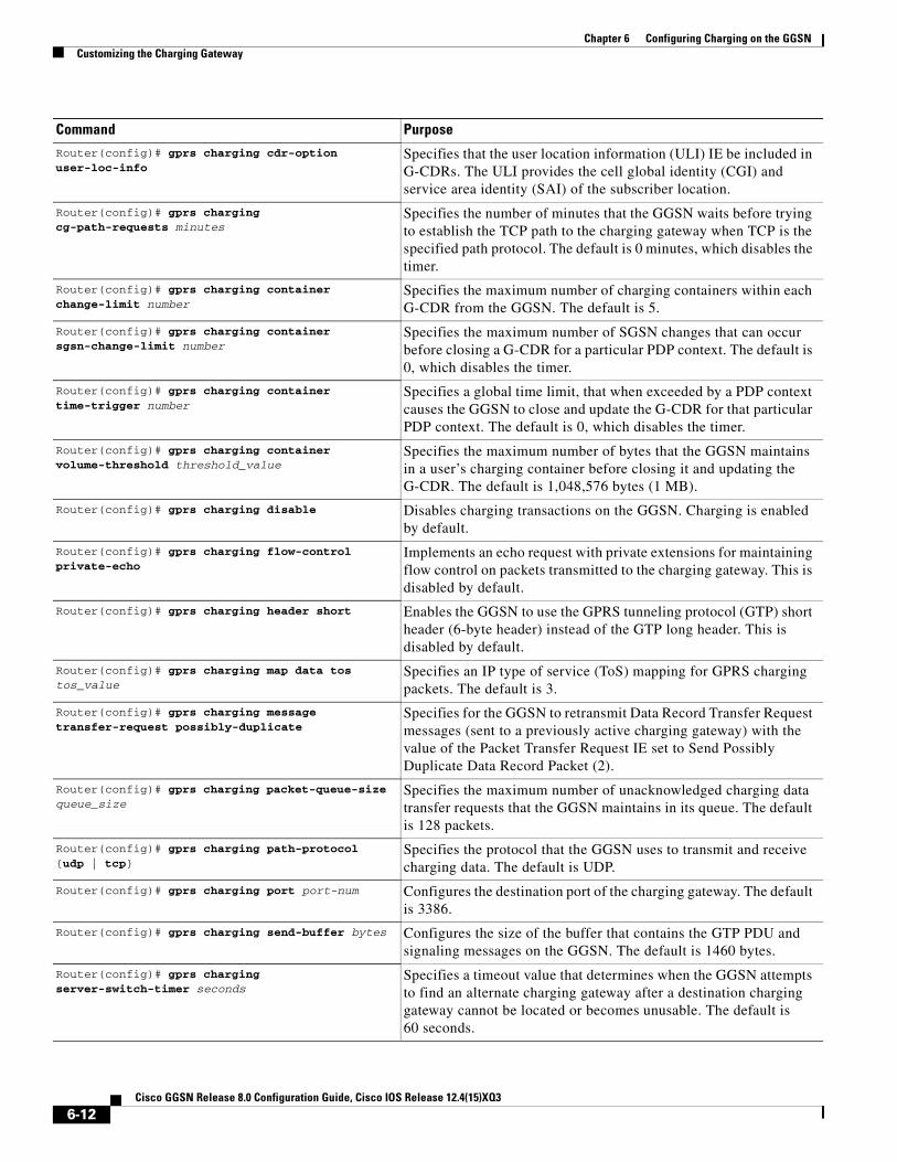
Chapter 6 Configuring Charging on the GGSNCustomizing the Charging Gateway
Router(config)# gprs charging cdr-option user-loc-info
Specifies that the user location information (ULI) IE be included in G-CDRs. The ULI provides the cell global identity (CGI) and service area identity (SAI) of the subscriber location.
Router(config)# gprs charging cg-path-requests minutes
Specifies the number of minutes that the GGSN waits before trying to establish the TCP path to the charging gateway when TCP is the specified path protocol. The default is 0 minutes, which disables the timer.
Router(config)# gprs charging container change-limit number
Specifies the maximum number of charging containers within each G-CDR from the GGSN. The default is 5.
Router(config)# gprs charging container sgsn-change-limit number
Specifies the maximum number of SGSN changes that can occur before closing a G-CDR for a particular PDP context. The default is 0, which disables the timer.
Router(config)# gprs charging container time-trigger number
Specifies a global time limit, that when exceeded by a PDP context causes the GGSN to close and update the G-CDR for that particular PDP context. The default is 0, which disables the timer.
Router(config)# gprs charging container volume-threshold threshold_value
Specifies the maximum number of bytes that the GGSN maintains in a user’s charging container before closing it and updating the G-CDR. The default is 1,048,576 bytes (1 MB).
Router(config)# gprs charging disable Disables charging transactions on the GGSN. Charging is enabled by default.
Router(config)# gprs charging flow-control private-echo
Implements an echo request with private extensions for maintaining flow control on packets transmitted to the charging gateway. This is disabled by default.
Router(config)# gprs charging header short Enables the GGSN to use the GPRS tunneling protocol (GTP) short header (6-byte header) instead of the GTP long header. This is disabled by default.
Router(config)# gprs charging map data tos tos_value
Specifies an IP type of service (ToS) mapping for GPRS charging packets. The default is 3.
Router(config)# gprs charging message transfer-request possibly-duplicate
Specifies for the GGSN to retransmit Data Record Transfer Request messages (sent to a previously active charging gateway) with the value of the Packet Transfer Request IE set to Send Possibly Duplicate Data Record Packet (2).
Router(config)# gprs charging packet-queue-size queue_size
Specifies the maximum number of unacknowledged charging data transfer requests that the GGSN maintains in its queue. The default is 128 packets.
Router(config)# gprs charging path-protocol {udp | tcp}
Specifies the protocol that the GGSN uses to transmit and receive charging data. The default is UDP.
Router(config)# gprs charging port port-num Configures the destination port of the charging gateway. The default is 3386.
Router(config)# gprs charging send-buffer bytes Configures the size of the buffer that contains the GTP PDU and signaling messages on the GGSN. The default is 1460 bytes.
Router(config)# gprs charging server-switch-timer seconds
Specifies a timeout value that determines when the GGSN attempts to find an alternate charging gateway after a destination charging gateway cannot be located or becomes unusable. The default is 60 seconds.
Command Purpose
6-12Cisco GGSN Release 8.0 Configuration Guide, Cisco IOS Release 12.4(15)XQ3

Chapter 6 Configuring Charging on the GGSNDisabling Charging Processing
For information about configuring GGSN GTP options, see the “Customizing the GGSN Configuration” section on page 3-14 in the “Configuring GTP Services on the GGSN” chapter.
Disabling Charging Processing
Caution The gprs charging disable command removes charging data processing on a GGSN, which means that the data required to bill customers for network usage is neither being collected by the GGSN nor being sent to the charging gateway. We recommend that you avoid using this command in production GPRS/UMTS network environments. When it is necessary to use this command, use it with extreme care and reserve its usage only under nonproduction network conditions.
You can disable charging on the GGSN only after all the open CDRs have been processed and sent to the charging gateway. To clear the current GGSN CDRs, use the clear gprs charging cdr privileged EXEC command.
Router(config)# gprs charging tariff-time time Specifies a time of day when GPRS/UMTS charging tariffs change. There is no default tariff time.
Note If the system software clock is manually set using the clock set privileged EXEC command at the supervisor console prompt, the time a tariff change will occur must be reconfigured.
Router(config)# gprs charging message transfer-request command-ie
Specifies for the GGSN to include the Packet Transfer Command information element (IE) in Data Record Transfer Response messages.
Note Even though GGSN 4.0 and later supports the Packet Transfer Command IE, only the “Send Data Record Packet” value is used, even though the packet might be duplicated. The Cisco GGSN does not support the “Send Possibly Duplicated Data Record Packet,” “Cancel Data Record Packet,” or “Release Data Record Packet” values. Therefore, the CG or billing servers must have the ability to eliminate duplicate CDRs.
Router(config)# gprs charging message transfer-response number-responded
Specifies for the GGSN to use the Number of Requests Responded field instead of the Length field in the Requests Responded IE of Data Record Transfer Response messages. This is disabled by default.
Router(config)# gprs charging reconnect minutes Configures the GGSN to periodically attempt to reconnect to a CG that is unreachable to determine when the link is back up.
Note Configuring the GGSN to automatically attempt to reconnect to a unreachable CG is necessary only when UDP is used as the charging transport protocol and the charging gateway does not support echo requests.
Router(config)# gprs charging transfer interval seconds
Specifies the number of seconds that the GGSN waits before it transfers charging data to the charging gateway. The default is 105 seconds.
Command Purpose
6-13Cisco GGSN Release 8.0 Configuration Guide, Cisco IOS Release 12.4(15)XQ3

Chapter 6 Configuring Charging on the GGSNUsing Charging Profiles
To disable charging processing on a GGSN, use the following command, beginning in global configuration mode:
Using Charging ProfilesYou can apply different charging methods on a per-PDP basis using charging profiles that you create, customize, and specify as the default charging method to use for a specific type of user at an APN level and global level. Charging profiles provide the ability to offer flexible services that are customized to subscriber preferences.
When using charging profiles, note the following:
• The GGSN must be configured to include the charging characteristics selection mode parameter in CDRs using the gprs charging cdr-option chch-selection-mode global configuration command.
• The GGSN must be configured to receive the charging characteristics selection mode IE in CDRs by using the gprs charging release global configuration command.
To apply charging methods on a per-PDP basis using GGSN charging profiles, you must complete the tasks outline in the following sections:
• Configuring a Charging Profile, page 6-14
• Defining the Charging Characteristics and Triggers of the Charging Profile, page 6-16
• Applying a Default Charging Profile to an APN, page 6-17
• Applying a Global Default Charging Profile, page 6-18
• Configuring How the GGSN Handles PDPs with Unmatched Charging Profiles, page 6-18
Configuring a Charging ProfileCharging profiles define the charging method to apply to a specific type of user (home, roamer, visitor).
The GGSN supports up to 256 charging profiles numbered 0 to 255.
Profile 0 is a set profile that always exists on the GGSN. It is not created by a GGSN operator, however, it can be modified using the charging-related global configuration commands. Profiles 1 to 255 are user-defined and customized using charging profile configuration commands.
When a Create PDP Context request is received, an appropriate charging profile is selected based on the following sources of input:
• SGSN/HLR via the charging characteristics IE.
• Local defaults.
• Charging profile index AAA attribute.
Command PurposeRouter(config)# gprs charging disable Disables charging transactions on the GGSN.
6-14Cisco GGSN Release 8.0 Configuration Guide, Cisco IOS Release 12.4(15)XQ3

Chapter 6 Configuring Charging on the GGSNUsing Charging Profiles
Note The charging profile index received from AAA will take effect only if service-awareness has been configured globally on the GGSN (using the gprs service-aware global configuration command), and at the APN level (using the service-aware access-point configuration command). For information on configuring a service-aware GGSN, see the “Configuring Enhanced Service-Aware Billing” chapter of the Cisco GGSN Configuration Guide.
The order in which a charging profile is selected for a PDP context, is as follows:
1. Charging profile index in the override rule on the APN—If a default charging profile has been configured at both the APN and global level to override the SGSN specification, the APN default charging profile is used first.
2. Charging profile index in the override rule on the box (global default charging profile)—If there is no default charging profile default configured at the APN, the default charging profile configured globally is use.
3. Charging profile index from AAA.
4. Charging profile index from SGSN/HLR
5. Charging profile index from the non-override rule on the APN.
6. Charging profile index from non-override rule on the box (global default charging profile).
If none of the above applies, the PDP context is rejected if the gprs charging characteristics reject global configuration command is configured and the create request is GTP v1. If the gprs charging characteristics reject command is not configured, the GTPv1 PDP context is created using charging profile 0.
Note The default charging profile, i.e. charging profile 0, is not supported for service-aware PDPs. These PDP create requests will be rejected with error code 199.
To create or modify a charging profile and enter charging profile configuration mode, use the following global configuration command:
Command PurposeRouter(config)# gprs charging profile chp-num Creates a new charging profile (or modifies an existing one), and
enters charging profile configuration mode. Valid values are 1 to 15.
6-15Cisco GGSN Release 8.0 Configuration Guide, Cisco IOS Release 12.4(15)XQ3

Chapter 6 Configuring Charging on the GGSNUsing Charging Profiles
Defining the Charging Characteristics and Triggers of the Charging ProfileTo configure the charging methods and triggers of a charging profile, use the following commands in charging profile configuration mode:
Command Purpose
Router(ch-prof-conf)# category {hot | flat | prepaid | normal}
Identifies the category of subscriber to which a charging profile applies.
Router(ch-prof-conf)# cdr suppression Specifies that CDRs be suppressed.
Router(ch-prof-conf)# cdr suppression prepaid Specifies that CDRs be suppressed for prepaid users.
Router(ch-prof-conf)# content dcca profile profile-name
Specifies the profile to use to communicate with a DCCA server.
Router(ch-prof-conf)# content postpaid {qos-change | sgsn-change | plmn-change | rat-change}
Configures a condition in a charging profile for postpaid users, that when it occurs, triggers the GGSN to request quota reauthorization for a PDP context.
• qos-change—Configures a quality of service (QoS) change to trigger a quota reauthorization request.
• sgsn-change—Configures a SGSN change to trigger a quota reauthorization request.
• plmn-change—Configures a public land mobile network (PLMN) change to trigger a quota reauthorization request.
• rat-change—Configures a radio access technology (RAT) change to trigger a quota reauthorization request.
Note The plmn-change and rat-change keyword options require that the GGSN has been configured to include the RAT and/or PLMN ID fields in the service-record IE in CDRs using the gprs charging service record include global configuration command.
Router(ch-prof-conf)# content postpaid time Configures, as a trigger condition for postpaid users when service aware billing is enabled, the time duration limit that when exceeded, causes the GGSN to collect upstream and downstream traffic byte counts and close and update the G-CDR for a particular PDP context.
Router(ch-prof-conf)# content postpaid validity Configures, as a trigger condition in a charging profile for postpaid users when service-aware billing is enabled, the amount of time quota granted to a user is valid.
Router(ch-prof-conf)# content postpaid volume Configures, as a trigger condition for postpaid users when service aware billing is enabled, the maximum number of bytes that the GGSN maintains across all containers for a particular PDP context before closing and updating the G-CDR.
Router(ch-prof-conf)# content rulebase id Defines a default rulebase ID to apply to PDP contexts.
Router(ch-prof-conf)# description Specifies the name or a brief description of a charging profile.
6-16Cisco GGSN Release 8.0 Configuration Guide, Cisco IOS Release 12.4(15)XQ3

Chapter 6 Configuring Charging on the GGSNUsing Charging Profiles
Applying a Default Charging Profile to an APNTo configure a default charging profile to use for a specific type of user at an APN, use the following access-point configuration command:
Router(ch-prof-conf)# limit volume number [reset]
Configures the maximum number of bytes that can be reported in each CDR from an active PDP context before the GGSN closes and updates the CDR, and opens a partial CDR for the PDP context while it remains in session on the GGSN.
If the reset keyword option is configured, the volume trigger is reset if the CDR is closed by any other trigger. If the reset keyword is not specified, the volume trigger will not be reset when the time trigger expires (limit duration command), but it will be reset when any other trigger expires.
Router(ch-prof-conf)# limit duration number [reset]
Configures, as a trigger condition, the time duration limit (in minutes) that when exceeded causes the GGSN to collect upstream and downstream traffic byte counts and close and update the G-CDR for a particular PDP context.
If the reset keyword option is configured, the time trigger is reset if the CDR is closed by any other trigger. If the reset keyword is not specified, the time trigger will not be reset when the volume trigger expires (limit volume command), but it will be reset when any other trigger expires.
Router(ch-prof-conf)# tariff-time Specifies that a charging profile use the global tariff change time configured using the gprs charging tariff-time global configuration command.
Router(ch-prof-conf)# limit sgsn-change Specifies that a charging profile use the global tariff changes configured using the gprs charging tariff-time global configuration command.
Command Purpose
Command PurposeRouter(config-access-point)# charging profile {home | roaming | visiting | any} [trusted] chp_num [override]
Configures a default charging profile to be used for a specific type of user at an APN.
6-17Cisco GGSN Release 8.0 Configuration Guide, Cisco IOS Release 12.4(15)XQ3

Chapter 6 Configuring Charging on the GGSNConfiguring G-CDR Backup and Retrieval using iSCSI
Applying a Global Default Charging ProfileDefault charging profiles configured at the global level are used when a default charging profile has not been specified for an APN.
To configure a default charging profile to use for a specific type of user globally, use the following global configuration command:
Configuring How the GGSN Handles PDPs with Unmatched Charging ProfilesThe GGSN can be configured to reject or accept GTPv1 Create PDP Context requests for which a profile cannot be matched. If configured to accept these PDP context requests, the charging method defined by charging profile 0 is applied. By default, the Create PDP Context requests are accepted and the charging method defined in charging profile 0 is applied.
The following restrictions apply to charging profiles selected for service-aware PDPs:
• All PDP s belonging to the same user must use the same charging profile as that of the primary PDP.
• The default charging profile, i.e. charging profile 0, is not supported for service-aware PDPs. These PDP create requests will be rejected with error code 199.
To configure a GGSN to reject Create PDP Context requests for which a charging profile cannot be matched, use the following global configuration command:
Configuring G-CDR Backup and Retrieval using iSCSIThe Cisco GGSN Release 8.0 and later utilizes the Cisco IOS software Small Computer Systems Interface over IP (iSCSI) support, as defined in RFC 3720, to enable G-CDR storage and retrieval from storage target on a Storage Area Network (SAN).
This section contains the following topics on iSCSI support on the GGSN:
• iSCSI Overview, page 6-18
• Configuring iSCSI G-CDR Backup and Storage on the GGSN, page 6-19
• Monitoring and Maintaining iSCSI G-CDR Backup and Storage, page 6-22
Command Purpose
Router(config)# gprs charging profile default {home | roaming | visiting | any} [trusted] chp_num [override]
Applies a global default charging profile for a specific type of user.
Command PurposeRouter(config)# gprs charging characteristics reject
Configures the GGSN to reject GTPv1 Create PDP Context requests for which a charging profile cannot be selected.
6-18Cisco GGSN Release 8.0 Configuration Guide, Cisco IOS Release 12.4(15)XQ3

Chapter 6 Configuring Charging on the GGSNConfiguring G-CDR Backup and Retrieval using iSCSI
iSCSI OverviewThe iSCSI transport protocol operates over TCP/IP, enabling mobile operators and service providers to use their SAN connected to an iSCSI interface to save complete DTR messages containing closed CDRs.
SAN technology, which enables customers to build scalable storage solutions, is comprised of the following primary elements:
• SCSI—An interface standard which enables multiple devices to be installed on a system, attached to cable to form a chain of devices. Each device is assigned a unique ID, which is expressed as a number, that identifies that device on the bus. SCSI IDs can be broken into Logical Unit Numbers (LUNs), enabling a number of devices to share a single SCSI ID. Devices from which I/O requests originate are called initiators, and devices from which responses originate are called targets.
• SAN—Technology that involves moving network storage to a separate network of its own. Disk, tape, and optical storage can then be attached to the storage network that is based on a fabric of switches and hubs that connects storage devices to a heterogeneous set of servers.
A SAN system provides block-level access to data residing on shared storage arrays through dedicated storage networks.
• iSCSI—Transport protocol that maps SCSI requests and responses over TCP and provides block-level data transfer between the SCSI initiator (the Cisco GGSN is this example), and the target (the storage device on the SAN). The initiator sends I/O requests and the target sends I/O responses.
A SAN topology is distinguished by the following features
• Storage is not directly connected to network clients
• Storage is not directly connected to servers
• Storage devices are interconnected
• Multiple servers can share multiple storage devices
Configuring iSCSI Backup and Storage on the GGSNIn the SCSI environment, the GGSN functions as an iSCSI initiator.
To enable G-CDR backup storage on an iSCSI device, you must first configure an iSCSI target profile on the GGSN that includes the name and IP address of the target, and the TCP port on which to “listen” for iSCSI traffic. Once the profile has been configured, you then configure the GGSN to use the interface for record storage when a charging gateway is not available.
With Cisco GGSN Release 9.0 and later, up to 30 iSCSI target profiles can be configured and associated with a set of unique charging gateways within a charging group.
As an alternative, an iSCSI target profile can be configured as the primary storage for CDRs by only configuring an iSCSI target profile and no charging gateway at the global level (default charging group 0), or at the APN level by defining only an iSCSI target in the charging group associated with an APN (charging groups 1 to 29).
The I/O requests sent by the GGSN are converted into SCSI requests and transported over TCP/IP to the remote storage target.
6-19Cisco GGSN Release 8.0 Configuration Guide, Cisco IOS Release 12.4(15)XQ3

Chapter 6 Configuring Charging on the GGSNConfiguring G-CDR Backup and Retrieval using iSCSI
Choosing the Record Format when Writing to iSCSI
By default, when writing DTRs to iSCSI, the format for storing records is “GTP,” wherein the complete DTR is written to the iSCSI target. As an alternative, the iSCSI record format can be configured as ASN.1 using the gprs charging iscsi rec-format command in global configuration mode and specifying the asn.1 keyword option. When ASN.1 is configured as the record format, the GGSN writes only the raw ASN1-encoded CDRs into iSCSI without embedding the DTR information element into the records. This format is useful when the records are retrieved from iSCSI using FTP.
To configure the record format, use the gprs charging iscsi rec-format command in global configuration mode.
Writing DTRs when iSCSI is used as Backup Storage
• Once iSCSI backup storage configuration is in place, when a charging gateway is not reachable, the writing towards the iSCSI is initiated. The complete DTR message is sent to the iSCSI target defined in the target profile.
• The recommended iSCSI record format when using iSCSI as backup is GTP (the default format). If the iSCSI auto-retrieval (gprs auto-retrieve global configuration command) is enabled, the record format must be configured as GTP.
• When iSCSI auto-retrieval is enabled, along with sending the complete DTR message, the GGSN adds a 12-byte header in front of the message before storing it to SAN. This header is used when the DTRs are retrieved and sent to the charging gateway. (In addition, the RSM-layer adds a 12-byte header and 4-byte trailer to the message before it is stored).
Note If the DTRs are retrieved directly from the SAN through other means such as FTP, then each record must skip the 10-byte header to get to the actual DTR containing encoded CDRs.
Writing DTRs when iSCSI is used as Primary Storage
• When there are no charging gateways configured, and only an iSCSI target profile is defined at the global charging level (charging group 0), or granular charging level (charging groups 1 to 29), the iSCSI is the primary storage for writing charging records.
• Although any iSCSI record format can be used, the ASN.1 iSCSI record format would enable the user to store raw ASN.1 encoded CDRs into iSCSI without any additional headers.
Note The records in ASN.1 format are generated only when gprs auto-retrieve is disabled on the GGSN, which is the default behavior. The ASN.1 format should be used only when the iSCSI target is used as the primary storage for charging records (no charging gateways are configured).
Reading CDRs
• Once the iSCSI backup storage configuration is in place, when a charging gateway comes up, the iSCSI initiator (GGSN) will request for any iSCSI records to be received from the iSCSI target.
• Once the GGSN receives a record, the 12-byte header added by the GGSN when the write process is removed and the complete DTR is sent to the charging gateway.
If the DTRs are to be marked for possibly duplicate before sending to the charging gateway, GGSN has to be configured with the following charging config command.
– gprs charging message transfer-request command-ie
– gprs charging message transfer-request possibly-duplicate
6-20Cisco GGSN Release 8.0 Configuration Guide, Cisco IOS Release 12.4(15)XQ3

Chapter 6 Configuring Charging on the GGSNConfiguring G-CDR Backup and Retrieval using iSCSI
iSCSI Restrictions
When configuring iSCSI G-CDR backup and storage on the GGSN, note the following:
• Currently, iSCSI targets cannot be dynamically discovered.
• The number of TCP connections per iSCSI session is limited to one.
• The iSCSI target device should be preformatted. Each LUN must have only one FAT32 partition.
• Maximum of size of a LUN must not be more than 2TB, which is the maximum disk size supported by a FAT32 file system.
When configuring iSCSI G-CDR Backup and Storage on the GGSN, complete the tasks in the following sections:
• Configuring an iSCSI Target Profile, page 6-22
• Associating an iSCSI Target Profile, page 6-23
• Verifying the iSCSI Session, page 6-23
Configuring an iSCSI Target Interface Profile
Note Up to 30 iSCSI profiles can be configured on the GGSN, however, only one target can be defined per profile, and only one profile at a time can be associated with the GGSN to use the iSCSI interface using the gprs iscsi command in global configuration mode.
To configure the iSCSI target interface profile on the GGSN, complete the following tasks, beginning in global configuration mode:
Note The name, ip, and port iSCSI interface sub configurations are required. For a complete list of optional configurations that you can configure under a target interface profile, issue the “?” command while in iSCSI interface configuration mode or see the ip iscsi target-profile command description in the Cisco GGSN Release 8.0 Command Reference.
Command Purpose
Step 1 Router(config)# ip iscsi target-profile target_profile_name
Creates an iSCSI target interface profile for the target and enters iSCSI interface configuration mode on the GGSN.
Step 2 Router(config-iscsi)# name target name (Required) Name of the iSCSI target.
Step 3 Router(config-iscsi)# ip ip_address (Required) IP address of the iSCSI target.
Step 4 Router(config-iscsi)# port tcp port (Required) Number of the TCP “listening” port on the target. The default is 3260.
Step 5 Router(config-iscsi)# source-interface loopback_interface_number
(Optional) Number of the loopback interface if iSCSI traffic is to use a diffferent source interface.
Step 6 Router(config-iscsi)# vrf vrf_name (Optional) Name of the VRF instance if iSCSI traffic needs a VPN.
Step 7 Router(config-iscsi)# exit Exits from iSCSI interface configuration mode.
6-21Cisco GGSN Release 8.0 Configuration Guide, Cisco IOS Release 12.4(15)XQ3

Chapter 6 Configuring Charging on the GGSNConfiguring G-CDR Backup and Retrieval using iSCSI
Associating an iSCSI Target Interface Profile
To configure the GGSN to use the iSCSI interface for G-CDR storage when no charging gateway is available, use the following command in global configuration mode:
Verifying the iSCSI Session
To verify that the iSCSI session is up, use the following command in privileged EXEC mode:
Monitoring and Maintaining iSCSI G-CDR Backup and StorageThe following is a list of commands that you can use to monitor and maintain the iSCSI backup and storage functions on the GGSN:
Command PurposeRouter(config)# gprs iscsi target_profile_name Configures the GGSN to use a iSCSI profile for record
storage.
Note Only one profile can be defined at a time.
Note The profile name specified must be the same as the one configured using the ip iscsi target-profile command.
Command PurposeRouter# show ip iscsi session Displays the status of iSCSI session.
Command PurposeRouter# clear gprs iscsi statistics Clears GGSN iSCSI processing statistics.
Router# clear ip iscsi statistics Clears iSCSI processing statistics.
Router# clear record-storage-module Clears record storage module statistics.
Router# show ip iscsi name Displays the name of the iSCSI initiator.
Router# show ip iscsi session Displays the status of an iSCSI session.
Router# show ip iscsi stats Displays the iSCSI and SCSI layer statistics.
Router# show ip iscsi target Displays the iSCSI target details.
Router# show record-storage-module stats Displays record storage module statistics.
Router# show record-storage-module target-info [all | target-profile profile_name]
Displays all disks available and their status, or the disk defined by a target profile.
6-22Cisco GGSN Release 8.0 Configuration Guide, Cisco IOS Release 12.4(15)XQ3

Chapter 6 Configuring Charging on the GGSNMonitoring and Maintaining Charging on the GGSN
Monitoring and Maintaining Charging on the GGSNThis section provides a summary list of the show commands that you can use to monitor charging functions on the GGSN.
The following privileged EXEC commands are used to monitor and maintain charging on the GGSN:
Command PurposeRouter# show gprs charging parameters Displays information about the current GGSN charging
configuration.
Router# show gprs service-mode Displays the current global service mode state of the GGSN and the last time it was changed.
Router# show gprs charging statistics Displays cumulative statistics about the transfer of charging packets between the GGSN and charging gateways.
6-23Cisco GGSN Release 8.0 Configuration Guide, Cisco IOS Release 12.4(15)XQ3

Chapter 6 Configuring Charging on the GGSNConfiguration Examples
Configuration ExamplesThe following are examples of charging configurations implemented on the GGSN.
Global Charging Configuration
GGSN ConfigurationRouter# show running-configBuilding configuration...
Current configuration :7390 bytes!! Last configuration change at 16:56:05 UTC Wed Jun 25 2003! NVRAM config last updated at 23:40:27 UTC Fri Jun 13 2003!version 12.3.....interface GigabitEthernet0/0.2 description Ga/Gn Interface encapsulation dot1Q 101 ip address 10.1.1.72 255.255.255.0 no cdp enable!.....ip route 40.1.2.1 255.255.255.255 10.1.1.1!gprs access-point-list gprs access-point 1 access-point-name auth-accounting access-mode non-transparent aaa-group authentication first aaa-group accounting second ip-address-pool dhcp-proxy-client dhcp-server 10.60.0.1 dhcp-gateway-address 10.60.0.1 exit !. . .!gprs default charging-gateway 10.9.0.2gprs charging send-buffer 1000gprs charging container volume-threshold 500000gprs charging container change-limit 3gprs charging cdr-aggregation-limit 10gprs charging cdr-option apn-selection-modegprs charging cdr-option served-msisdn!gprs memory threshold 512!. . .!end
Supervisor Engine ConfigurationSup# show running-configBuilding configuration...
Current configuration :12672 bytes
6-24Cisco GGSN Release 8.0 Configuration Guide, Cisco IOS Release 12.4(15)XQ3

Chapter 6 Configuring Charging on the GGSNConfiguration Examples
!version 12.2...interface FastEthernet8/22 no ip address switchport switchport access vlan 302!interface Vlan101 description Vlan to GGSN for GA/GN ip address 10.1.1.1 255.255.255.0!interface Vlan302 ip address 40.0.2.1 255.255.255.0
Charging Profile ConfigurationThe following partial configuration example shows two charging profiles (charging profile 1 and charging profile 2) configured on the GGSN, with charging profile 1 being configured as the global default charging profile to be used for “any” type of user if a charging profile is not specified at the APN:
Router# show running-configBuilding configuration...
Current configuration :7390 bytes!! Last configuration change at 16:56:05 UTC Wed Jun 25 2003! NVRAM config last updated at 23:40:27 UTC Fri Jun 13 2003!version 12.3.....interface GigabitEthernet0/0.2 description Ga/Gn Interface encapsulation dot1Q 101 ip address 10.1.1.72 255.255.255.0 no cdp enable!.....ip route 40.1.2.1 255.255.255.255 10.1.1.1!!. . .!gprs charging profile default any 1
gprs charging profile 1 description "roamer_profile" limit volume 500000 reset limit duration 30 reset!gprs charging profile 2 description "any_unmatched" limit volume 1000000 reset limit duration 60 reset. . .!. . .!end
6-25Cisco GGSN Release 8.0 Configuration Guide, Cisco IOS Release 12.4(15)XQ3

Chapter 6 Configuring Charging on the GGSNConfiguration Examples
6-26Cisco GGSN Release 8.0 Configuration Guide, Cisco IOS Release 12.4(15)XQ3

Cisco GGSN Release 8.0
C H A P T E R7
Configuring Enhanced Service-Aware BillingThis chapter describes how to implement the Cisco Gateway GPRS Support Node (GGSN) as a service-aware GGSN that is capable of real-time credit-control for prepaid users, as well as service-aware billing for postpaid and prepaid users.
Note Service-aware GGSN functionality is supported for IPv4 PDP contexts only.
For a complete description of the GGSN commands in this chapter, refer to the Cisco GGSN Command Reference for the Cisco GGSN release you are using. To locate documentation of other commands that appear in this chapter, use the command reference master index or search online.
This chapter includes the following sections:
• Service-Aware GGSN Overview, page 7-1
• Configuring a Service-Aware GGSN, page 7-5
• Configuration Example, page 7-28
Service-Aware GGSN OverviewThe Cisco GGSN can be configured with the Cisco Content Services Gateway - 2nd Generation (CSG2) and Cisco IOS Diameter protocol/Diameter Credit Control Application (DCCA) to support real-time credit-control for prepaid users and service-aware billing for postpaid and prepaid users.
Note As an alternate online billing solution that does not include DCCA, the GGSN can be configured to support Online Charging Server (OCS) address selection. OCS address selection enables online credit control for prepaid users to be provided by an external OCS to which the Cisco CSG2 has a direct GTP’ interface. When this support is configured, the GGSN functions as a quota server for postpaid subscribers only and does not generate enhanced G-CDRs (eG-CDRs) for prepaid users. For more information about the OCS address selection support on the GGSN, see the “Configuring OCS Address Selection Support” section on page 7-27.
The GGSN and Cisco CSG together, function as a service-aware GGSN.
The Cisco CSG categorizes traffic, reports usage, and management quota. The GGSN provides a Diameter interface to the DCCA server via which the Cisco CSG can request quota and report usage. The GGSN also maintains all PDP contexts and determines if they are prepaid or postpaid.
7-1Configuration Guide, Cisco IOS Release 12.4(15)XQ3

Chapter 7 Configuring Enhanced Service-Aware BillingService-Aware GGSN Overview
If service-based charging is required (prepaid or postpaid), entries are created on the Cisco CSG. The Cisco CSG inspects the service categories and reports usage back to the GGSN. If the user is to be treated as a postpaid user (offline charging), the GGSN records usage information that is reported by the Cisco CSG in eG-CDRs. If the user is to be treated as a prepaid user (online charging), the GGSN records the reported usage information in eG-CDRs, and translates and sends the information to a DCCA server.
The GGSN also handles Gn-side triggers for quota reauthorization and server-initiated reauthorization or termination requests. The Cisco CSG sends the authorization requests, quota reports, and service stops to the GGSN, which in turn translates them into DCCA messages for transport over the Diameter interface. When the DCCA server responds with additional quota, the GGSN pushes it to the Cisco CSG.
Note If RADIUS is not being used, the Cisco CSG must be configured as a RADIUS proxy.
Figure 7-1 provides illustrates the functions and characteristics the service-aware GGSN with DCCA providing online charging support.
Figure 7-1 High-Level Overview of Service-Aware GGSN Functions with DCCA being used for Online Charging Support
IP
GGSN Standby
service-awareGGSN
SGSN
AAA
Functions:· Quota to Category Mapping· Quota Grant based on PDP
Roaming status, QoS,balance / credit, etc.
Functions:· Supports GTP'· Packet Inspection· Radius Proxy for non-
DCCA traffic· Billing Plan· Service Name· Content Definition
Charging / Billing Server(Rulebase, Business Logic)
service-aware GGSN
DiameterDCCA-S CGW
DiameterDCCA-C
CSG Standby
CSG Active
Gn
DiameterDCCA-C
Radius
GGSN Active
RadiusAcct
GTP'(QS)
GTP'
Characteristics:· Quota negotiation· Based on DCCA· TCP transport
Functions:· Traffic Categorization· Quota Management· Quota Consumption· Quota Usage Tracking· Quota Status Reporting· Time and Volume Based
Functions:· Quota Management· Functions as a QS for CSG· DCCA rulebase ID maps to
CSG billing plan· Per-category quota maps to
CSG service quota· DCCA-S Failover
DiameterDCCA
9262
2
7-2Cisco GGSN Release 8.0 Configuration Guide, Cisco IOS Release 12.4(15)XQ3

Chapter 7 Configuring Enhanced Service-Aware BillingService-Aware GGSN Overview
Supported Features
The primary new features supported by the GGSN to enable the configuration of a service-aware GGSN, include the following:
• Diameter base protocol and DCCA client interface support for online/real-time credit control for prepaid users (IP PDP contexts only)
• Quota server functionality and interface to Cisco CSG for per-service billing
• Enhanced G-CDRs for service-based CDRs for prepaid and postpaid subscribers
Additionally, GGSN Release 5.2 and later provides enhancements to the following existing interfaces:
• AAA authentication interface—DCCA rulebase support and charging profile selection
• AAA accounting interface—Required for Cisco CSG Known User Table (KUT) population and Cisco CSG-based proxies
• Ga—Enhanced offline charging interface
Unsupported Features
The following features are not supported with the service aware feature in GGSN Release 5.2:
• Charging differentiation for secondary PDP contexts
• PPP PDP contexts
• PPP Regeneration
• Network Management
• Cell identity
• PDP contexts for both online DCCA exchange and offline service-based usage
• Dynamic configuration for blocking/forwarding traffic while waiting for quota reauthorization
• Diameter proxy, relay, or redirection
• Diameter transport layer security
• SCTP transport
• No Dual Quota Support (for receiving Volume and Time quota)
Service-Aware GGSN Data FlowsThe following is a high-level overview of the flow of traffic during the creation of a PDP context for a prepaid subscriber in an enhanced service-aware billing implementation using the service-aware GGSN.
PDP Context Creation Data Flow for Prepaid Users
1. The SGSN sends a create PDP context request to the service-aware GGSN.
2. The GGSN sends an Access-Request message to the RADIUS server or Cisco CSG configured as a RADIUS proxy.
3. The RADIUS returns an Access-Accept response. From the Access-Accept response, the GGSN obtains a default rulebase ID, or if the response does not contain a default rulebase ID, the GGSN obtains the rulebase ID from a locally configured value in the charging profile selected for this create PDP context request.
4. The service-aware GGSN sends a Credit Control Request (CCR) to the DCCA server.
7-3Cisco GGSN Release 8.0 Configuration Guide, Cisco IOS Release 12.4(15)XQ3

Chapter 7 Configuring Enhanced Service-Aware BillingService-Aware GGSN Overview
5. The DCCA server sends a Credit Control Answer (CCA) to the GGSN. This CCA may contain a rulebase and quota request.
6. If it contains a rulebase, the GGSN sends an Accounting-Start request with the selected rulebase to the RADIUS.
7. The RADIUS receives the Accounting-Start request and creates a KUT for the user.
8. The RAIDUS sends an Accounting Start response to the GGSN.
9. If the DCCA server sends a quota request is received in a CCA to the GGSN and the GGSN pushes the quota request to the Cisco CSG2.
10. When the GGSN receives a quota push response from the Cisco CSG2, it sends the create PDP context response to the SGSN and the context is established.
PDP Context Creation Data Flow for Postpaid Users
1. The SGSN sends a create PDP context request to the service-aware GGSN.
2. The GGSN sends an Accounting-Start request containing selected rulebase to the RADIUS endpoint (Cisco CSG2 configured as a RADIUS proxy).
3. The RADIUS proxy receives Accounting-Start request and creates a KUT for the user.
4. The RAIDUS sends an Accounting Start response to the GGSN.
5. The GGSN sends a create PDP context response to the SGSN and the context is established.
PrerequisitesImplementing a service-aware GGSN requires the following:
• A Cisco 7600 series router in which a Cisco Supervisor Engine 720, with a Multilayer Switch Feature Card (Cisco Product ID: SUP720-MSFC3-BXL), running Cisco IOS Release 12.2(33)SRB1 or later.
For details on upgrading the Cisco IOS release running on the supervisor engine, see the “Upgrading to a New Software Release” section in the Release Notes for Cisco IOS Release 12.2SR.
Note The Cisco IOS software required on the supervisor engine is dependent on the supervisor engine being used and the Cisco IOS software application running on the Cisco SAMI PCCs. For information on these hardware and software requirements, refer to the documentation of the Cisco IOS mobile wireless application that you are implementing on the Cisco SAMI.
• Cisco Service and Application Module for IP (Cisco Product Number: WS-SVC-SAMI-BB-K9), running Cisco IOS Release 12.4(15)XQ and later on the SAMI processors. (The image is automatically loaded onto each processor during an image upgrade.)
• IPSec VPN Services Module (for security)
• A Cisco SAMI running the Cisco Content Services Gateway - 2nd Generation (CSG2) software in each Cisco 7600 series router.
7-4Cisco GGSN Release 8.0 Configuration Guide, Cisco IOS Release 12.4(15)XQ3

Chapter 7 Configuring Enhanced Service-Aware BillingConfiguring a Service-Aware GGSN
• On the SGSN, the values configured for the number GTP N3 requests and T3 retransmissions must be larger than the sum of all possible server timers (RADIUS, DCCA, and Cisco CSG).
Specifically the SGSN N3*T3 must be greater than:
2 x RADIUS timeout + N x DCCA timeout + Cisco CSG2 timeout
where:
– 2 is for both authentication and accounting.
– N is for the number of diameter servers configured in the server group.
Limitations and RestrictionsBefore implementing enhanced service-aware billing, note the following:
• If session redundancy is needed, the GGSN supports a maximum of 21 categories per user.
• RADIUS accounting is enabled between the Cisco CSG and GGSN to populate the KUT entries with the PDP context user information
• The Cisco CSG2 must be configured with the quota server addresses of all the GGSN instances.
• The service IDs on the Cisco CSG must be configured as numeric strings that match the category IDs on the DCCA server.
• If RADIUS is not being used, the Cisco CSG2 must be configured as a RADIUS proxy on the GGSN.
Configuring a Service-Aware GGSNTo configure a service-aware GGSN, complete the tasks in the following sections:
• Enabling Service-Aware Billing Support, page 7-5 (Required)
• Configuring the Quota Server Interface, page 7-7 (Required)
• Configuring Diameter/DCCA Interface Support, page 7-12 (Required)
• Configuring the Enhanced Billing Parameters in Charging Profiles, page 7-22 (Required)
• Configuring OCS Address Selection Support, page 7-27 (Optional)
Enabling Service-Aware Billing SupportEnhanced service-aware billing must be enabled on the GGSN before you can configure a service-aware GGSN.
7-5Cisco GGSN Release 8.0 Configuration Guide, Cisco IOS Release 12.4(15)XQ3

Chapter 7 Configuring Enhanced Service-Aware BillingConfiguring a Service-Aware GGSN
To enable service-aware billing support on the GGSN, complete the following task while in global configuration mode:
To enable service-aware billing support on a particular access-point, complete the following task while in access-point configuration mode.
If service-aware billing is enabled on an APN, the GGSN must be configured to wait for a RADIUS accounting response before sending a create PDP context response to the SGSN.
To configure the GGSN to wait for a RADIUS accounting response before sending a create PDP context response to the SGSN, complete the following task while in global configuration mode:
Enabling Enhanced G-CDRsG-CDRs contain information for the entire duration of, or part of, a PDP context. The G-CDR includes information such as the subscriber (MSISDN, IMSI), APN used, QoS applied, SGSN ID (as the mobile access location), a time stamp and duration, the data volume recorded separately for the upstream and downstream direction, and volume thresholds for intermediate CDR generation and tariff time switches.
In addition to the above, an eG-CDR contains a service-record part that contains the usage data of each service flow used by a PDP session (specified by category ID). For example, the upstream and downstream volume, and the duration is recorded per service flow.
By default, the GGSN does not include the service-record information in G-CDRs. To support a service-aware GGSN implementation, the GGSN must be configured to generate eG-CDRs.
To configure the GGSN to include the service-record information in G-CDRs, use the following command while in global configuration mode:
Command PurposeRouter(config)# gprs service-aware Configures a service-aware GGSN.
Command PurposeRouter(access-point-config)# service-aware Enables an APN to support service-aware billing.
Command PurposeRouter(config)# gprs gtp response-message wait-accounting Configures the GGSN to wait for a RADIUS
accounting response before sending a create PDP context response to the SGSN.
Command PurposeRouter(config)# gprs charging cdr-option service-record [1-100]
Configures the GGSN to include service-record information in G-CDRs and specifies the maximum number of service records a G-CDR can contain before the G-CDR is closed and a partial G-CDR is opened. The default is 5.
7-6Cisco GGSN Release 8.0 Configuration Guide, Cisco IOS Release 12.4(15)XQ3

Chapter 7 Configuring Enhanced Service-Aware BillingConfiguring a Service-Aware GGSN
Configuring the Quota Server InterfaceTogether, the Cisco CSG2 and GGSN, configured as a service-aware GGSN, provide the following functions:
• The Cisco CSG2:
– Inspects packets and categorizes traffic
– Requests quota and reports usage
– Provides billing plans, service names, and content definitions
– Acts as a RADIUS proxy for non-DCCA traffic
– Functions in prepaid mode for each service-flow charge recording
For detailed information about configuring the Cisco CSG2, see Cisco Content Services Gateway - 2nd Generation Installation and Configuration Guide.
http://www.cisco.com/en/US/products/sw/wirelssw/ps779/products_configuration_guide_book09186a0080856678.html
• The GGSN:
– Functions as a quota server to the Cisco CSG2
– Provides the Diameter interface to the DCCA server for quota requests and returns
– Manages the quota requested by the Cisco CSG2 and received from the DCCA server
– Maps DCCA server rulebases to Cisco CSG2 billing plans
– Maps DCCA server category quota to Cisco CSG2 service quota
To configure the quota server interface on the GGSN, complete the tasks in the following sections:
• Configuring a Cisco CSG2 Server Group, page 7-7 (Required)
• Configuring the Quota Server Process on the GGSN, page 7-8 (Required)
• Configuring the GGSN to use the Cisco CSG2 as an Authentication and Accounting Proxy, page 7-10 (Required if RADIUS is not being used)
• Monitoring and Maintaining, page 7-11
Configuring a Cisco CSG2 Server Group
We recommend that two Cisco CSG2s (one Active, the other Standby) be configured to function as one when interacting with the quota server process on the GGSN. When configuring the Cisco CSG2 group that the quota server process will use to communicate with the Cisco CSG2, a virtual IP address must be specified along with the real IP addresses of each of the Cisco CSG2s that make up the redundant pair. The quota server process communicates with the virtual address and the active Cisco CSG2 listens to the virtual IP address.
7-7Cisco GGSN Release 8.0 Configuration Guide, Cisco IOS Release 12.4(15)XQ3

Chapter 7 Configuring Enhanced Service-Aware BillingConfiguring a Service-Aware GGSN
To configure a Cisco CSG2 group on the GGSN, complete the following tasks, beginning in global configuration mode:
Configuring the Quota Server Process on the GGSN
The quota server process on the GGSN supports the following attributes in Accounting Start messages to the Cisco CSG2:
• Billing Plan ID—Corresponds with the rulebase ID received from the DCCA server. The quota server process on the GGSN maps the rulebase ID to the billing plan ID.
• Quota server address and port—IP address and port of the quota server the Cisco CSG2 should use for a user.
By default, this is the IP address of the GGSN unless OCS address selection support is configured on the GGSN. For more information about OCS address selection support on the GGSN, see “Configuring OCS Address Selection Support” section on page 7-27.
• Downlink nexthop address—Next hop address (user address) for downlink traffic (Cisco CSG2-to-GGSN).
In addition, the quota server process supports the following TLVs:
• Quota Consumption Timer (QCT). The QCT is assumed to be zero.
• Quota Holding Timer (QHT)
• Quota Threshold
For more information on enhancements to the quota server interface, billing plans, and the QCT and QHT, see the Cisco Content Services Gateway Installation and Configuration Guide.
Note One quota server process can be configured per GGSN. Configuring more than one quota server process will overwrite the existing process.
Command Purpose
Step 1 Router(config)# ggsn csg csg-group-name Specifies a name for the Cisco CSG2 server group and enters Cisco CSG2 group configuration mode.
Step 2 Router(config-csg-group)# virtual-address ip-address Specifies the virtual IP address of the Cisco CSG2 group. This is the IP address that the quota server process on the GGSN uses to communicate with the Cisco CSG2.
Step 3 Router(config-csg-group)# port port-number (Optional) Configures the port on which the Cisco CSG2 listens for communications from the quota server. The default is 3386.
Note The Cisco CSG2 always sends messages to the quota server on port 3386.
Step 4 Router(config-csg-group)# real-address ip-address Configures the IP address of a real Cisco CSG2 for source checking on inbound messages from a Cisco CSG2. Configure an real IP address for each of the Cisco CSG2s that make up the redundant pair.
7-8Cisco GGSN Release 8.0 Configuration Guide, Cisco IOS Release 12.4(15)XQ3
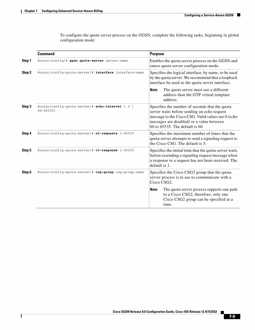
Chapter 7 Configuring Enhanced Service-Aware BillingConfiguring a Service-Aware GGSN
To configure the quota server process on the GGSN, complete the following tasks, beginning in global configuration mode:
Command Purpose
Step 1 Router(config)# ggsn quota-server server-name Enables the quota server process on the GGSN and enters quota server configuration mode.
Step 2 Router(config-quota-server)# interface interface-name Specifies the logical interface, by name, to be used by the quota server. We recommend that a loopback interface be used as the quota server interface.
Note The quota server must use a different address than the GTP virtual template address.
Step 3 Router(config-quota-server)# echo-interval [ 0 | 60-65535]
Specifies the number of seconds that the quota server waits before sending an echo request message to the Cisco CSG. Valid values are 0 (echo messages are disabled) or a value between 60 to 65535. The default is 60.
Step 4 Router(config-quota-server)# n3-requests 1-65535 Specifies the maximum number of times that the quota server attempts to send a signaling request to the Cisco CSG. The default is 5.
Step 5 Router(config-quota-server)# t3-response 1-65535 Specifies the initial time that the quota server waits before resending a signaling request message when a response to a request has not been received. The default is 1.
Step 6 Router(config-quota-server)# csg-group csg-group-name Specifies the Cisco CSG2 group that the quota server process is to use to communicate with a Cisco CSG2.
Note The quota server process supports one path to a Cisco CSG2, therefore, only one Cisco CSG2 group can be specified at a time.
7-9Cisco GGSN Release 8.0 Configuration Guide, Cisco IOS Release 12.4(15)XQ3

Chapter 7 Configuring Enhanced Service-Aware BillingConfiguring a Service-Aware GGSN
Advertising the Next Hop Address For Downlink Traffic
To configure the next hop address (the user address) for downlink traffic (Cisco CSG2-to-GGSN) to be advertised in Accounting Start requests to the RADIUS endpoint, complete the following task while in access-point configuration mode:
Configuring the GGSN to use the Cisco CSG2 as an Authentication and Accounting Proxy
If RADIUS is not being used, the Cisco CSG2 must be configured as a RADIUS endpoint.
To configure the GGSN to use the Cisco CSG2 as a RADIUS proxy, you must complete the following tasks:
1. Define the RADIUS server globally.
2. Define a AAA RADIUS server group and include the Cisco CSG2 as a server in the server group.
3. Specify the type of services the server group will support using AAA method lists.
4. Reference the method list in APNs that will use the Cisco CSG2 as a RADIUS proxy.
To specify the RADIUS server globally, complete the following tasks while in global configuration mode:
To define a AAA RADIUS server group, and include the Cisco CSG2 as a server in the server group, complete the following tasks, beginning in global configuration mode:
Command PurposeGGSN(access-point-config)# advertise downlink next-hop ip-address
Configures the next hop address, to which downlink traffic destined for the GGSN will be routed, to be advertised in Accounting Start requests.
Command Purpose
Step 1 Router(config)# radius-server host {hostname | ip-address} [auth-port port-number] [acct-port port-number]
Specifies a RADIUS server host.
Step 2 Router(config)# radius-server key {0 string | 7 string | string}
Sets the authentication and encryption key for all RADIUS communications between the GGSN and the RADIUS daemon.
Command Purpose
Step 1 Router(config)# aaa group server radius group-name Specifies a AAA server group and assigns the selected server group for authentication services.
Step 2 Router(config-sg-radius)# server ip_address [auth-port port-number] [acct-port port-number]
Configures the IP address of the RADIUS server in the server group.
Step 3 Router(config-sg-radius)# exit Exits server group configuration mode.
7-10Cisco GGSN Release 8.0 Configuration Guide, Cisco IOS Release 12.4(15)XQ3

Chapter 7 Configuring Enhanced Service-Aware BillingConfiguring a Service-Aware GGSN
To specify the types of services the group will support using AAA method lists, complete the following tasks, beginning in global configuration mode:
To reference the method list in APNs that will use the Cisco CSG2 as a RADIUS proxy, complete the following tasks while in access-point configuration mode:
Monitoring and MaintainingUse the following privilege EXEC commands to monitor and maintain the quota server-to-Cisco CSG2 configuration.
Command Purpose
Step 1 Router(config)# aaa authentication ppp list-name group group-name
Specifies one or more AAA authentication methods for use on serial interfaces that are running PPP.
Step 2 Router(config)# aaa authorization network list-name group group-name
Sets parameters that restrict network access to a user.
Step 3 Router(config)# aaa accounting network list-name start-stop group group-name
Enables AAA accounting of requested services for billing or security purposes when you use RADIUS.
Command Purpose
Step 1 Router(access-point-config)# aaa-group authentication server-name
Specifies a AAA server group and assigns the selected server group for authentication services on the access point.
Step 2 Router(access-point-config)# aaa-group accounting server-name
Specifies the logical interface, by name, to be used by the quota server.
Command PurposeRouter# clear ggsn quota-server statistics Clears quota server-related statistics (messages and error
counts).
Router# show ggsn quota-server [parameters | statistics]
Displays quota server parameters or statistics about quota server messages and error counts.
Router# show ggsn csg [parameters | statistics] Displays the parameters used by the Cisco CSG2 group or the number of path and quota management messages sent and received by the quota server.
7-11Cisco GGSN Release 8.0 Configuration Guide, Cisco IOS Release 12.4(15)XQ3

Chapter 7 Configuring Enhanced Service-Aware BillingConfiguring a Service-Aware GGSN
Configuring Diameter/DCCA Interface SupportThe GGSN functions as a DCCA client when communicating with a DCCA server to provide the following functions:
• Diameter interface to the DCCA server for online/real-time credit for prepaid subscribers
• Negotiates quota by sending quota requests from the Cisco CSG2 to the DCCA server and pushing quota returns from the DCCA server to the Cisco CSG2
• Maps DCCA server rulebases to Cisco CSG2 billing plans
• Maps DCCA server category quota to Cisco CSG2 service quota
Messaging
The GGSN DCCA client process and DCCA server exchange the following messages:
• Credit Control Request (CCR)—Initial, Update, and Final
• Credit Control Answer (CCA)—Initial, Update, and Final
The GGSN Diameter interface supports the following Diameter base messages:
• Capability Exchange Request (CER) and Capability Exchange Answer (CEA)—The GGSN advertises DCCA support in CER messages. In addition, the GGSN can be configured to advertise support for vendor-specific AVPs using the diameter vendor support global configuration command.
• Disconnect Peer Request (DPR) and Disconnect Peer Answer (DPA)—The GGSN sends a DPR message when the CER with a Diameter peer fails or there is no Diameter server configured.
• Device Watchdog Request (DWR) and Device Watchdog Answer (DWA)—The GGSN uses DWR and DWA messages to detect transport failures with a Diameter peer. A watchdog timer can be configured for each Diameter peer using the timer watchdog Diameter peer configuration command.
• Re-auth Request (RAR) and Re-auth Answer (RAA)
• Abort Session Request (ASR) / Abort Session Answer (ASA)—Note that no Failed-AVP is sent in an ASA when an incorrect ASR is sent from the DCCA server.
Additionally, as a DCCA client, the GGSN receives the following notifications from Cisco IOS AAA:
• Receipts of CCA messages
• Asynchronous session termination requests
• Server-initiated RARs
To configure Diameter/DCCA support, complete the tasks in the following sections:
• Configuring the Diameter Base, page 7-13
• Configuring the DCCA Client Process on the GGSN, page 7-18
• Enabling Support for Vendor-Specific AVPs in DCCA Messages, page 7-22
7-12Cisco GGSN Release 8.0 Configuration Guide, Cisco IOS Release 12.4(15)XQ3

Chapter 7 Configuring Enhanced Service-Aware BillingConfiguring a Service-Aware GGSN
Configuring the Diameter Base
To configure the Diameter protocol base, complete the tasks in the following sections:
• Configuring a Diameter Peer, page 7-13
• Enabling Diameter AAA, page 7-15
• Configuring Diameter Protocol Parameters Globally, page 7-16
• Monitoring and Maintaining the Diameter Base, page 7-18
Configuring a Diameter Peer
To configure a Diameter peer, use the following commands, beginning in global configuration mode:
.
Command Purpose
Step 1 Router(config)# diameter peer peer-name Defines a Diameter peer and enters Diameter peer configuration mode.
Step 2 Router(config-dia-peer)# address ipv4 ip-address Configures a route to the host of the Diameter peer using IPv4.
Step 3 Router(config-dia-peer)# transport {tcp | sctp} port port-num
Configures the transport protocol to use to connect to the Diameter peer.
Note The Cisco GGSN supports TCP.
Step 4 Router(config-dia-peer)# security ipsec Configures IPSec as the security protocol to use for the Diameter peer-to-peer connection.
Step 5 Router(config-dia-peer)# source interface interface Configures the interface to use to connect to the Diameter peer.
7-13Cisco GGSN Release 8.0 Configuration Guide, Cisco IOS Release 12.4(15)XQ3
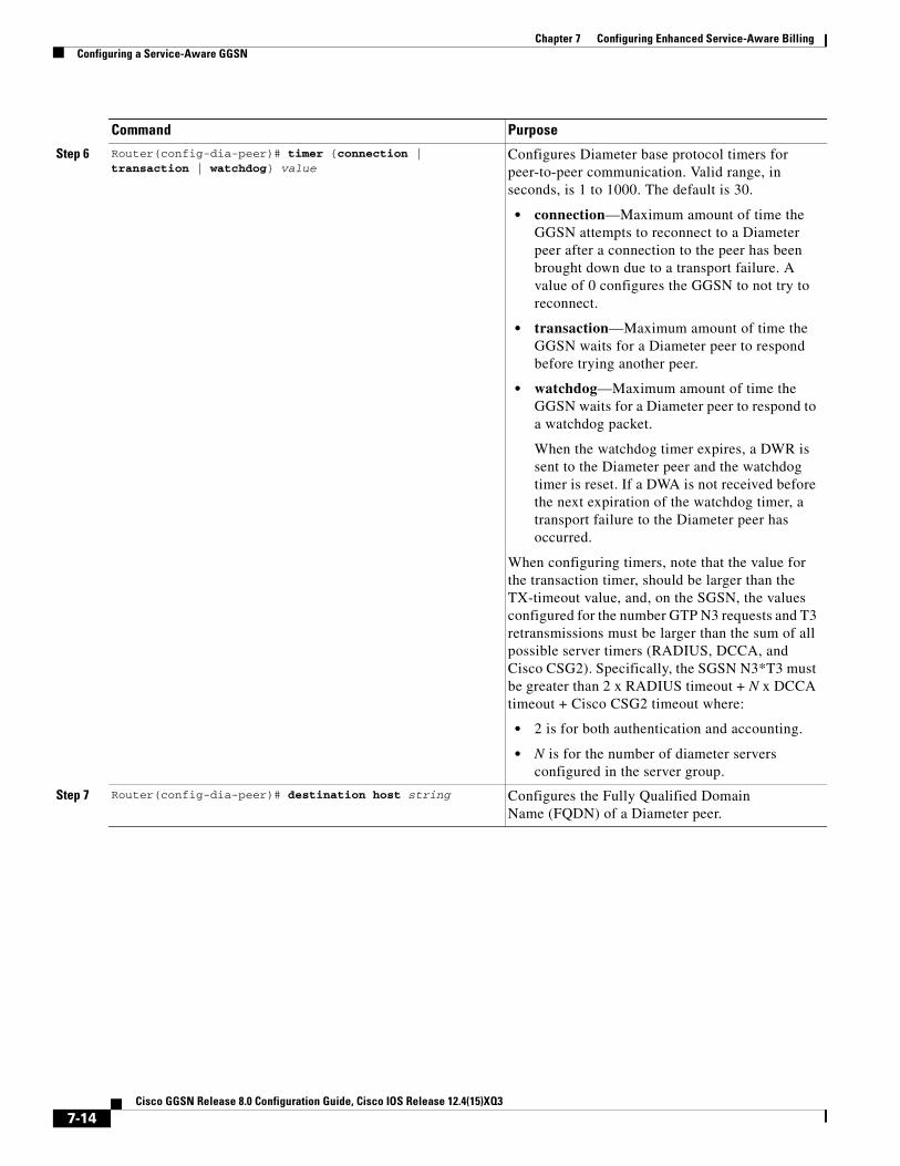
Chapter 7 Configuring Enhanced Service-Aware BillingConfiguring a Service-Aware GGSN
Step 6 Router(config-dia-peer)# timer {connection | transaction | watchdog} value
Configures Diameter base protocol timers for peer-to-peer communication. Valid range, in seconds, is 1 to 1000. The default is 30.
• connection—Maximum amount of time the GGSN attempts to reconnect to a Diameter peer after a connection to the peer has been brought down due to a transport failure. A value of 0 configures the GGSN to not try to reconnect.
• transaction—Maximum amount of time the GGSN waits for a Diameter peer to respond before trying another peer.
• watchdog—Maximum amount of time the GGSN waits for a Diameter peer to respond to a watchdog packet.
When the watchdog timer expires, a DWR is sent to the Diameter peer and the watchdog timer is reset. If a DWA is not received before the next expiration of the watchdog timer, a transport failure to the Diameter peer has occurred.
When configuring timers, note that the value for the transaction timer, should be larger than the TX-timeout value, and, on the SGSN, the values configured for the number GTP N3 requests and T3 retransmissions must be larger than the sum of all possible server timers (RADIUS, DCCA, and Cisco CSG2). Specifically, the SGSN N3*T3 must be greater than 2 x RADIUS timeout + N x DCCA timeout + Cisco CSG2 timeout where:
• 2 is for both authentication and accounting.
• N is for the number of diameter servers configured in the server group.
Step 7 Router(config-dia-peer)# destination host string Configures the Fully Qualified Domain Name (FQDN) of a Diameter peer.
Command Purpose
7-14Cisco GGSN Release 8.0 Configuration Guide, Cisco IOS Release 12.4(15)XQ3

Chapter 7 Configuring Enhanced Service-Aware BillingConfiguring a Service-Aware GGSN
Enabling Diameter AAA
To enable Diameter AAA, complete the tasks in the following sections:
• Defining the Diameter AAA Server Group, page 7-15
• Defining an Authorization Method List for Prepaid Subscribers, page 7-16
Defining the Diameter AAA Server Group
For redundancy, Diameter servers should be configured as Diameter AAA server groups that consist of a primary and secondary server.
To define a Diameter AAA server group, use the following commands, beginning in global configuration mode:.
Step 8 Router(config-dia-peer)# destination realm string Configures the destination realm (part of the domain “@realm”) in which a Diameter peer is located.
The realm might be added by the AAA client when sending a request to AAA. However, if the client does not add the attribute, then the value configured while in Diameter peer configuration mode is used when sending messages to the destination Diameter peer. If a value is not configured while in Diameter peer configuration mode, the value specified globally using the diameter destination realm global configuration command is used.
Step 9 Router(config-dia-peer)# ip vrf forwarding name Associates a VRF with a Diameter peer.
Note If a VRF name is not configure for a Diameter server, the global routing table will be used.
Command Purpose
Command Purpose
Step 1 Router(config)# aaa new-model Enables AAA.
7-15Cisco GGSN Release 8.0 Configuration Guide, Cisco IOS Release 12.4(15)XQ3

Chapter 7 Configuring Enhanced Service-Aware BillingConfiguring a Service-Aware GGSN
Defining an Authorization Method List for Prepaid Subscribers
To apply parameters that restrict access to a network for prepaid subscribers, use the following command while in global configuration mode:
Configuring Diameter Protocol Parameters Globally
Global Diameter protocol parameters are used if Diameter parameters have not been defined at a Diameter peer level.
Step 2 Router(config)# aaa group server diameter server Defines a Diameter AAA server group.
Configuring AAA server groups allows different servers to be used for each element of AAA. It also defines a redundant set of servers for each element.
Step 3 Router(config-sg-diameter)# server name auth-port 1645 acct-port 1646
Configures the name of the Diameter server for the Diameter AAA server group.
The name specified for this command should match the name of a Diameter peer defined using the diameter peer command.
Note The above port numbers are defaults, for authorization and accounting, respectively. Explicit port numbers are required only if non-default ports are used.
Command Purpose
Command PurposeRouter(config)# aaa authorization prepaid method_list group server_group [group server_group]
Defines an authorization method list for prepaid subscribers and defines the Diameter AAA groups to send records.
7-16Cisco GGSN Release 8.0 Configuration Guide, Cisco IOS Release 12.4(15)XQ3

Chapter 7 Configuring Enhanced Service-Aware BillingConfiguring a Service-Aware GGSN
To configure global Diameter parameters, complete the following tasks while in global configuration mode:
Command Purpose
Step 1 Router(config)# diameter timer {connection | transaction | watchdog} value
Configures Diameter base protocol timers to use if none have been configured at the Diameter peer level. Valid range, in seconds, is 0 to 1000. The default is 30.
• connection—Maximum amount of time the GGSN attempts to reconnect to a Diameter peer after a connection to the peer has been brought down due to a transport failure. A value of 0 configures the GGSN to not try to reconnect.
• transaction—Maximum amount of time the GGSN waits for a Diameter peer to respond before trying another peer.
• watchdog—Maximum amount of time the GGSN waits for a Diameter peer to respond to a watchdog packet.
When the watchdog timer expires, a DWR is sent to the Diameter peer and the watchdog timer is reset. If a DWA is not received before the next expiration of the watchdog timer, a transport failure to the Diameter peer has occurred.
When configuring timers, note that the value for the transaction timers, should be larger than the value for the TX timer, and, on the SGSN, the values configured for the number GTP N3 requests and T3 retransmissions must be larger than the sum of all possible server timers (RADIUS, DCCA, and Cisco CSG2). Specifically, the SGSN N3*T3 must be greater than 2 x RADIUS timeout + N x DCCA timeout + Cisco CSG2 timeout where:
• 2 is for both authentication and accounting.
• N is for the number of diameter servers configured in the server group.
Step 2 Router(config)# diameter redundancy Enables the Diameter node to be a Cisco IOS Redundancy Facility (RF) client and track session states.
The Diameter base does not initiate a connection to a Diameter peer that is in standby mode. Upon a standby-to-active mode transition, a connection to the newly active peer is established.
Note This command is required for Service-aware PDP session redundancy. For more information about service-aware PDP session redundancy, see the “GTP-Session Redundancy for Service-Aware PDPs Overview” section on page 7-26.
Step 3 Router(config)# diameter origin realm string
Configures the realm of origin (part of the domain “@realm”) in which this Diameter node is located.
Origin realm information is sent in requests to a Diameter peer.
7-17Cisco GGSN Release 8.0 Configuration Guide, Cisco IOS Release 12.4(15)XQ3

Chapter 7 Configuring Enhanced Service-Aware BillingConfiguring a Service-Aware GGSN
Monitoring and Maintaining the Diameter Base
Use the following privilege EXEC command to monitor and maintain Diameter peer configurations.
Configuring the DCCA Client Process on the GGSN
The GGSN functions as a DCCA client when interacting with the DCCA server to obtain and request quota. As a DCCA client, the GGSN sends CCR messages to and receives CCAs from the DDCA server for credit control session (one credit control session per PDP session). In addition, the defaults configured in the DCCA client profile dictate how the GGSN handles credit control sessions if a server failover should occur and no instructions are sent by the server.
Failure Handling Defaults on the DCCA Client
Two AVPs determine how the CC sessions are handled if a failover occurs:
• CC-Session-Failover AVP—Indicates that a CC session should fail over to the alternate Diameter server (set using the session-failover DCCA client profile configuration command).
• Credit-Control-Failure-Handling (CCFH)—Determines how the GGSN behaves if a failure does occur (set using the ccfh DCCA client profile configuration command)
Defaults for these AVPs can be configured in the DCCA client profile for failure handling, however, values received from the DCCA server will override the defaults configured on the GGSN.
The CCFH AVP is determines the action the DCCA client takes on a session, when the following fault conditions occur:
• Tx timeout expires.
• CCA message containing protocol error (Result-Code 3xxx) is received.
• CCA fails (for example, a CCA with a permanent failure notification [Result-Code 5xxx]) is received).
• Failure-to-send condition exists (the DCCA client is not able to communicate with the desired destination).
• An invalid answer is received
Step 4 Router(config)# diameter origin host string Configures the Fully Qualified Domain Name (FQDN) of the host of this Diameter node.
The origin host information is sent in requests to a Diameter peer.
Step 5 Router(config)# diameter vendor support {Cisco | 3gpp | Vodafone}
Configures this Diameter node to advertise the vendor AVPs it supports in capability exchange messages with Diameter peers.
Multiple instances of this command can be configured if the vendor IDs differ.
Command Purpose
Command Purpose
Router# show diameter peer Displays Diameter peer-related information.
7-18Cisco GGSN Release 8.0 Configuration Guide, Cisco IOS Release 12.4(15)XQ3

Chapter 7 Configuring Enhanced Service-Aware BillingConfiguring a Service-Aware GGSN
To configure a DCCA client profile, in which the details of a DCCA client process are defined and is referenced from the charging profile, use the following commands, beginning in global configuration mode:
.
Command Purpose
Step 1 Router(config)# gprs dcca profile name Defines the DCCA client process on the GGSN and enters DCCA client profile configuration mode.
Step 2 Router(config-dcca-profile)# authorization method_list_name
Defines the method list that is used to specify the Diameter AAA server groups.
Step 3 Router(config-dcca-profile)# tx-timeout seconds Configures a TX timeout value, in seconds, used by this DCCA client to monitor the communication of Credit Control Requests (CCRs) with a Diameter server.
Valid range is 1 to 1000 seconds. The default is 10.
When configuring timers, note that the value for the transaction timer, should be larger than the TX-timeout value, and, on the SGSN, the values configured for the number GTP N3 requests and T3 retransmissions must be larger than the sum of all possible server timers (RADIUS, DCCA, and Cisco CSG2). Specifically, the SGSN N3*T3 must be greater than 2 x RADIUS timeout + N x DCCA timeout + Cisco CSG2 timeout where:
• 2 is for both authentication and accounting.
• N is for the number of diameter servers configured in the server group.
7-19Cisco GGSN Release 8.0 Configuration Guide, Cisco IOS Release 12.4(15)XQ3

Chapter 7 Configuring Enhanced Service-Aware BillingConfiguring a Service-Aware GGSN
Step 4 Router(config-dcca-profile)# ccfh {continue | terminate | retry_terminate}
Configures the default Credit Control Failure Handling (CCFH) action to take on PDP contexts when a fault condition occurs.
• continue—Allows the PDP context and user traffic for the relevant category or categories to continue, regardless of the interruption. Quota management of other categories is not affected.
• terminate—Terminates the PDP context and the CC session.
• retry_terminate—Allows the PDP context and user traffic for the relevant category or categories to continue. Hard-coded quota (1 GB) is passed to the CSG2 when the first DCCA server is unavailable. The DCCA client retries to send the CRR to an alternate server and if a failure-to-send condition occurs with the alternate server, the PDP context is terminated.
The default is terminate.
A value from the DCCA server in a CCA overrides this default.
Step 5 Router(config-dcca-profile)# session-failover Specifies that a session should failover to the alternate DCCA server Configures Credit Control Session Failover (CCSF) AVP support when a CCA message from a DCCA server does not contain a value for the CCSF AVP.
By default, session failover is not supported.
Command Purpose
7-20Cisco GGSN Release 8.0 Configuration Guide, Cisco IOS Release 12.4(15)XQ3

Chapter 7 Configuring Enhanced Service-Aware BillingConfiguring a Service-Aware GGSN
Step 6 Router(config-dcca-profile)# destination-realm string Specifies the destination realm to be sent in CCR initial requests to the DCCA server. For subsequent CCRs, the Origin-Realm AVP received in the last CCA is used as the Destination-Realm.
Step 7 Router(config-dcca-profile)# trigger {sgsn-change | qos-change | rat | plmn-id}
Configures a change that, when it occurs, triggers the GGSN (functioning as a DCCA client) to request quota-reauthorization and generate an eG-CDR.
• sgsn-change—Configures a SGSN change to trigger a quota reauthorization request.
• qos-change—Configures a QoS change to trigger a quota reauthoriazation request.
• rat—Configures a RAT change to trigger a quota reauthorization request. The RAT indicates whether the SGSN serves the user equipment (UE) UMTS or GSM/EDGE RAN (GERAN).
• plmn-id—Configures a PLMN ID change to trigger a quota reauthorization request.
Modifying this command will not affect existing PDP contexts using a DCCA client profile. The plmn-change and rat-change keyword options require that the GGSN has been configured to include the RAT and/or PLMN ID fields in the service-record IE in CDRs using the gprs charging service record include global configuration command.
Note This command is supported by the generic DCCA client only.
Note With this release of the Cisco GGSN, all triggers must be explicitly enabled for both prepaid and postpaid users.
Command Purpose
7-21Cisco GGSN Release 8.0 Configuration Guide, Cisco IOS Release 12.4(15)XQ3

Chapter 7 Configuring Enhanced Service-Aware BillingConfiguring a Service-Aware GGSN
Enabling Support for Vendor-Specific AVPs in DCCA Messages
The GGSN can be configured to send Vodafone vendor-specific AVPs in DCCA messages to the DCCA server.
Table 7-1 lists and describes the Vodafone vendor-specific AVPs that the GGSN can be configured to send in DCCA messages.
To enable the GGSN to send Vodafone vendor-specific AVPs in DCCA messages to the DCCA server, complete the following task while in global configuration mode.
Configuring the Enhanced Billing Parameters in Charging ProfilesThe GGSN supports up to 255 charging profiles (numbered 0 to 255). Charging profiles 1 through 255 are configurable, charging profile 0 is a box-level default configured while in global configuration mode. For information on how a charging profile is selecting and how to configure charging profiles, see the Configuring Charging chapter.
In addition to the previous charging profile support, with GGSN Release 5.2 and later, the charging profile can also be configured to:
• Allow eG-CDRs
• Specify a default charging type (to be used primarily for a prepaid or postpaid user)
• DCCA server to contact for quota requests (presence indicates online charging)
• Suppress G-CDRs for all or only online charging
• Default rulebase-ID to apply to a user
To configure service-aware billing characteristics in a charging profile, complete the tasks in the following sections:
• Specifying a Default Rulebase ID, page 7-23
• Specifying a DCCA Client Profile to Use for Online Billing, page 7-23
• Suppressing CDRs for Prepaid Users, page 7-24
• Configuring Trigger Conditions for Postpaid Users, page 7-24
Table 7-1 Vodafone Vendor-Specific AVPs in CCRs
Number Vendor-Proprietary Attribute Description
Rulebase-ID Billing Plan ID (string)
Context-Type Type of PDP context (PRIMARY). For secondary PDP contexts, no CCR is sent. This AVP is sent in CCR (Initial) only.
User-Location-Info Cell Global Identification (CGI) is used as geographical location type. RAI, obtained from the SGSN, is sent.
Command PurposeRouter(config)# gprs dcca clci Configures the GGSN to send Vodafone vendor-specific
AVPs in DCCA messages to the server.
7-22Cisco GGSN Release 8.0 Configuration Guide, Cisco IOS Release 12.4(15)XQ3

Chapter 7 Configuring Enhanced Service-Aware BillingConfiguring a Service-Aware GGSN
Specifying a Default Rulebase ID
Rulebases contain the rules for defining categories of traffic; categories on which decisions such as whether to allow or disallow traffic, and how to measure the traffic, are based. The GGSN maps Diameter rulebase IDs to Cisco CSG2 billing plans.
To configure a default rulebase ID to apply to PDP contexts using a particular charging profile, use the following command while in charging profile configuration mode:
Note The rulebase value presented in a RADIUS Access Accept message overrides the default rulebase ID configured in a charging profile. A rulebase ID received in a CCA initial message from a DCCA server overrides the rulebase ID received from the RADIUS server and the default rulebase ID configured in a charging profile.
Specifying a DCCA Client Profile to Use for Online Billing
The charging profile is selected when the primary PDP context is created. If a DCCA profile has been configured in the charging profile, online billing is indicated. Therefore, regardless of whether or not a subscriber is prepaid or postpaid, the GGSN will contact the DCCA server if the content dcca profile configuration is present. If the subscriber is to be treated as a postpaid user, the DCCA server will return a CAA with a result-code of CREDIT_CONTROL_NOT_APPLICABLE (4011) and the user will be treated as a postpaid user.
If a charging profile does not contain a DCCA profile configuration, users are treated as postpaid (offline billing).
To specify the DCCA client profile to use to communicate with a DCCA server, use the following command while in charging profile configuration mode:
Command PurposeRouter(ch-prof-conf)# content rulebase id Defines a default rulebase ID to apply to PDP
contexts using this charging profile.
Command PurposeRouter(ch-prof-conf)# content dcca profile profile-name Specifies the profile to use to communicate with a
DCCA server.
7-23Cisco GGSN Release 8.0 Configuration Guide, Cisco IOS Release 12.4(15)XQ3
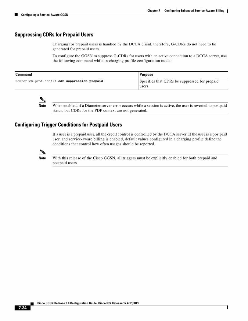
Chapter 7 Configuring Enhanced Service-Aware BillingConfiguring a Service-Aware GGSN
Suppressing CDRs for Prepaid Users
Charging for prepaid users is handled by the DCCA client, therefore, G-CDRs do not need to be generated for prepaid users.
To configure the GGSN to suppress G-CDRs for users with an active connection to a DCCA server, use the following command while in charging profile configuration mode:
Note When enabled, if a Diameter server error occurs while a session is active, the user is reverted to postpaid status, but CDRs for the PDP context are not generated.
Configuring Trigger Conditions for Postpaid Users
If a user is a prepaid user, all the credit control is controlled by the DCCA server. If the user is a postpaid user, and service-aware billing is enabled, default values configured in a charging profile define the conditions that control how often usages should be reported.
Note With this release of the Cisco GGSN, all triggers must be explicitly enabled for both prepaid and postpaid users.
Command PurposeRouter(ch-prof-conf)# cdr suppression prepaid Specifies that CDRs be suppressed for prepaid
users
7-24Cisco GGSN Release 8.0 Configuration Guide, Cisco IOS Release 12.4(15)XQ3

Chapter 7 Configuring Enhanced Service-Aware BillingConfiguring a Service-Aware GGSN
To define the trigger conditions, in a charging profile for postpaid users, use the following commands while in charging profile configuration mode:
Command Purpose
Step 1 Router(ch-prof-conf)# content postpaid {qos-change | sgsn-change | plmn-change | rat-change}
Configures the condition that when it occurs, causes the GGSN to request quota reauthorization for a PDP context.
• qos-change—Configures a quality of service (QoS) change to trigger a quota reauthorization request.
• sgsn-change—Configures a SGSN change to trigger a quota reauthorization request.
• plmn-change—Configures a public land mobile network (PLMN) change to trigger a quota reauthorization request.
• rat-change—Configures a radio access technology (RAT) change to trigger a quota reauthorization request.
Note The plmn-change and rat-change keyword options require that the GGSN has been configured to include the RAT and/or PLMN ID fields in the service-record IE in CDRs using the gprs charging service record include global configuration command.
Note With this release of the Cisco GGSN, all triggers must be explicitly enabled for both prepaid and postpaid users.
Step 2 Router(ch-prof-conf)# content postpaid time value Specifies the time duration limit that when exceeded, causes the GGSN to collect upstream and downstream traffic byte counts and close and update the G-CDR for a particular PDP context.
Valid value is between 300 and 4294967295 seconds. The default is 1048576.
Step 1 Router(ch-prof-conf)# content postpaid validity seconds
Specifies the amount of time, in seconds, that quota granted for a postpaid user is valid. Valid range is 900 to 4294967295 seconds. The default is no validity timer is configured.
Step 2 Router(ch-prof-conf)# content postpaid volume value Specifies the maximum number of bytes that the GGSN maintains across all containers for a particular PDP context before closing and updating the G-CDR.
Valid value is between 1 and 4294967295. The default is 1,048,576 bytes (1 MB).
7-25Cisco GGSN Release 8.0 Configuration Guide, Cisco IOS Release 12.4(15)XQ3
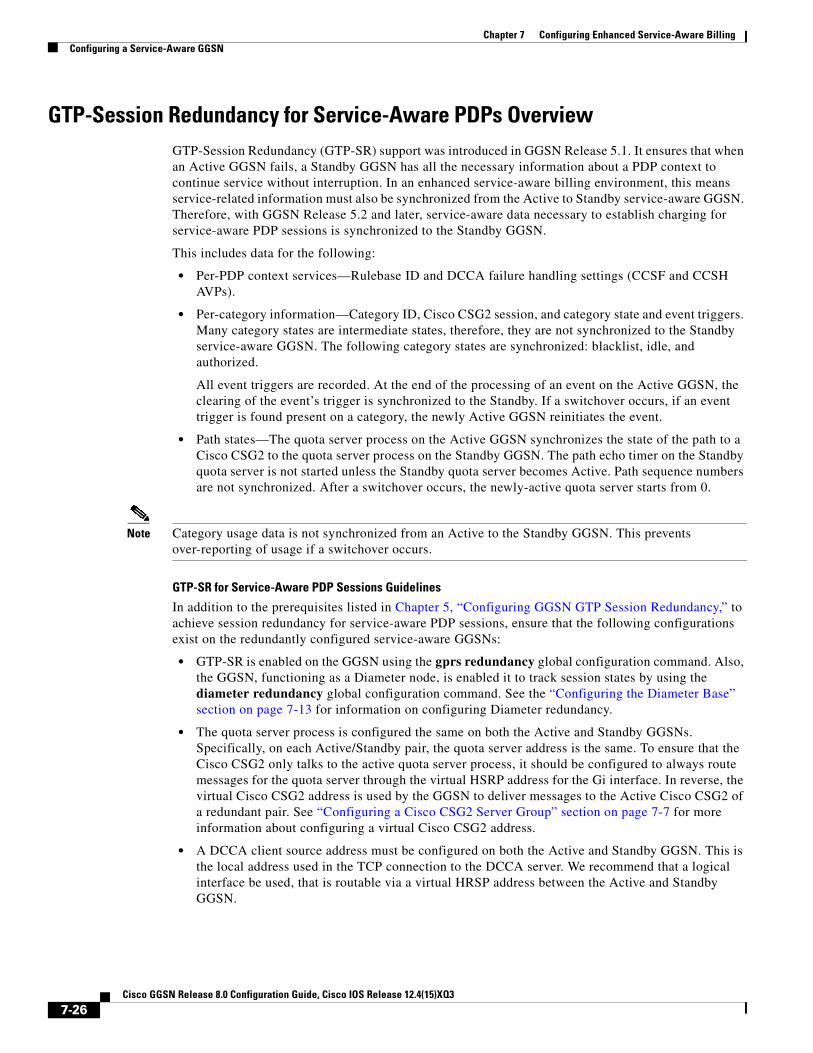
Chapter 7 Configuring Enhanced Service-Aware BillingConfiguring a Service-Aware GGSN
GTP-Session Redundancy for Service-Aware PDPs OverviewGTP-Session Redundancy (GTP-SR) support was introduced in GGSN Release 5.1. It ensures that when an Active GGSN fails, a Standby GGSN has all the necessary information about a PDP context to continue service without interruption. In an enhanced service-aware billing environment, this means service-related information must also be synchronized from the Active to Standby service-aware GGSN. Therefore, with GGSN Release 5.2 and later, service-aware data necessary to establish charging for service-aware PDP sessions is synchronized to the Standby GGSN.
This includes data for the following:
• Per-PDP context services—Rulebase ID and DCCA failure handling settings (CCSF and CCSH AVPs).
• Per-category information—Category ID, Cisco CSG2 session, and category state and event triggers. Many category states are intermediate states, therefore, they are not synchronized to the Standby service-aware GGSN. The following category states are synchronized: blacklist, idle, and authorized.
All event triggers are recorded. At the end of the processing of an event on the Active GGSN, the clearing of the event’s trigger is synchronized to the Standby. If a switchover occurs, if an event trigger is found present on a category, the newly Active GGSN reinitiates the event.
• Path states—The quota server process on the Active GGSN synchronizes the state of the path to a Cisco CSG2 to the quota server process on the Standby GGSN. The path echo timer on the Standby quota server is not started unless the Standby quota server becomes Active. Path sequence numbers are not synchronized. After a switchover occurs, the newly-active quota server starts from 0.
Note Category usage data is not synchronized from an Active to the Standby GGSN. This prevents over-reporting of usage if a switchover occurs.
GTP-SR for Service-Aware PDP Sessions Guidelines
In addition to the prerequisites listed in Chapter 5, “Configuring GGSN GTP Session Redundancy,” to achieve session redundancy for service-aware PDP sessions, ensure that the following configurations exist on the redundantly configured service-aware GGSNs:
• GTP-SR is enabled on the GGSN using the gprs redundancy global configuration command. Also, the GGSN, functioning as a Diameter node, is enabled it to track session states by using the diameter redundancy global configuration command. See the “Configuring the Diameter Base” section on page 7-13 for information on configuring Diameter redundancy.
• The quota server process is configured the same on both the Active and Standby GGSNs. Specifically, on each Active/Standby pair, the quota server address is the same. To ensure that the Cisco CSG2 only talks to the active quota server process, it should be configured to always route messages for the quota server through the virtual HSRP address for the Gi interface. In reverse, the virtual Cisco CSG2 address is used by the GGSN to deliver messages to the Active Cisco CSG2 of a redundant pair. See “Configuring a Cisco CSG2 Server Group” section on page 7-7 for more information about configuring a virtual Cisco CSG2 address.
• A DCCA client source address must be configured on both the Active and Standby GGSN. This is the local address used in the TCP connection to the DCCA server. We recommend that a logical interface be used, that is routable via a virtual HRSP address between the Active and Standby GGSN.
7-26Cisco GGSN Release 8.0 Configuration Guide, Cisco IOS Release 12.4(15)XQ3

Chapter 7 Configuring Enhanced Service-Aware BillingConfiguring a Service-Aware GGSN
For information on configuring Cisco IOS HRSP, see Configuring the Hot Standby Router Protocol section of the Cisco IOS IP Configuration Guide, Release 12.3. For detailed information on GTP-SR, see Chapter 5, “Configuring GGSN GTP Session Redundancy.”
For information about fault-tolerance on the Cisco CSG2, see Cisco Content Services Gateway - 2nd Generation Installation and Configuration Guide.
http://www.cisco.com/en/US/products/sw/wirelssw/ps779/products_configuration_guide_book09186a0080856678.html
Configuring OCS Address Selection SupportAs an alternate to the GGSN with DCCA online charging solution, the GGSN can be configured to support OCS address selection. OCS address selection support enables the Cisco CSG2 to communicate with an OCS, to which it has a direct GTP interface, for online credit control for prepaid users.
By default, the GGSN sends its own IP address in Accounting-Start messages to the Cisco CSG2 (functioning as a RADIUS proxy) to establish itself as the quota server for postpaid and prepaid users. However, when OCS address selection support is configured, if the IP address of an OCS is returned in the “csg:quota_server” attribute in an Access-Accept message from the AAA server, the GGSN forwards that address in the same attribute in an Accounting-Start message to the Cisco CSG2. This informs the Cisco CSG2 that the external OCS is to be used as the quota server for this PDP context, and the GGSN will function as the quota server for only postpaid users.
The flow of traffic for the creation of a PDP context for a prepaid subscriber when OCS address selection is configured is as follows:
1. The GGSN receives a create PDP context request from the SGSN.
2. The GGSN sends an Access-Request message to the AAA server.
3. The AAA server determines if the user is prepaid, and if so, responds with an Access-Accept that includes the “csg:quota_server” attribute containing the IP address and port of the external OCS.
4. The GGSN receives this Access-Accept, and, because the csg_quota_server attribute is present, determines that the subscriber is a prepaid subscriber and sends an Accounting-Start request to the Cisco CSG2 that also includes the csg:quota_server attribute containing the OCS IP address and port.
(If an Access-Accept does not contain the csg:quota_server attribute, the GGSN forwards its own IP address in the csg:quota_server field of the Accounting-Start request.)
5. The AAA server sends an Accounting Start response.
6. The GGSN sends a create PDP context response to the SGSN and context is established.
When an external OCS is used as the quota server for prepaid subscribers, the GGSN will receive service-level usage reports from the Cisco CSG2 for postpaid users and will generate eG-CDRs accordingly. The GGSN will not generate eG-CDRs for prepaid subscribers.
OCS address selection support on the GGSN requires the following conditions are met:
• Service-awareness is enabled globally and at the APN level (see “Enabling Service-Aware Billing Support” section on page 7-5).
• Wait accounting is enabled for the APN (using the gtp response-message wait-accounting access-point configuration command).
• GGSN is configured to communicate with the Cisco CSG2 (see “Configuring the Quota Server Interface” section on page 7-7).
7-27Cisco GGSN Release 8.0 Configuration Guide, Cisco IOS Release 12.4(15)XQ3

Chapter 7 Configuring Enhanced Service-Aware BillingConfiguration Example
• The GGSN is configured to generate eG-CDRs (see “Enabling Enhanced G-CDRs” section on page 7-6).
• The correct configuration exists on the AAA server.
To enable support for OCS address selection on the GGSN, use the following command while in global configuration mode:
Configuration ExampleThe following is an example of enhanced service-aware billing support configured on the GGSN.
Current configuration :3537 bytes!! Last configuration change at 15:26:45 UTC Fri Jan 7 2005!version 12.4service timestamps debug datetime msecservice timestamps log datetime msecno service password-encryptionservice gprs ggsn!hostname sup-samiA!boot-start-markerboot-end-marker!enable password abc!aaa new-model!!!Configures the CSG2 RADIUS server group!aaa group server radius CSG-groupserver 10.10.65.100 auth-port 1812 acct-port 1813!!Configures the Diameter server group!aaa group server diameter DCCAserver name DCCA!!!Assigns AAA services to the CSG2 RADIUS and Diameter server groups!aaa authentication ppp CSG-list group CSG-groupaaa authorization prepaid DCCA group DCCAaaa authorization network CSG-list group CSGaaa accounting network CSG-list start-stop group CSG-groupaaa session-id commonip subnet-zero!!
Command Purpose
Step 1 Router(conf)# gprs radius attribute quota-server ocs-address
Specifies the amount of time, in seconds, that quota granted for a postpaid user is valid. Valid range is 900 to 4294967295 seconds. The default is no validity timer is configured.
7-28Cisco GGSN Release 8.0 Configuration Guide, Cisco IOS Release 12.4(15)XQ3

Chapter 7 Configuring Enhanced Service-Aware BillingConfiguration Example
ip cef!!...!!gprs access-point-list gprs!...!!!Enables service-aware billing on the GGSN!gprs service-aware!gprs access-point-list gprs access-point 10 access-point-name cisco.com access-mode non-transparent aaa-group authentication CSG-list aaa-group accounting CSG-list gtp response-message wait-accounting charging profile any 1 override service-aware advertise downlink next-hop 10.10.150.2 ! access-point 20 access-point-name yahoo.com access-mode non-transparent aaa-group authentication CSG aaa-group accounting CSG gtp response-message wait-accounting charging profile any 1 override service-aware ! !!!Configures a DCCA client profile!gprs dcca profile 1 ccfh continue authorization CSG-list destination-realm cisco.com trigger sgsn-change trigger qos-change!gprs charging profile 1 limit volume 64000 limit duration 64000 content rulebase PREPAID content dcca profile 1 content postpaid volume 64000 content postpaid time 1200 content postpaid qos-change content postpaid sgsn-change!!Congigures the quota server!ggsn quota-server qs interface Loopback2 csg group csg_1 !!!Configures a CSG2 group
7-29Cisco GGSN Release 8.0 Configuration Guide, Cisco IOS Release 12.4(15)XQ3

Chapter 7 Configuring Enhanced Service-Aware BillingConfiguration Example
!ggsn csg-group csg_1 virtual-address 10.10.65.10 port 4386 real-address 10.10.65.2 !tftp-server abcbar!radius-server host 10.10.65.100 auth-port 1812 acct-port 1813radius-server host 10.20.154.201 auth-port 1812 acct-port 1813radius-server key abcradius-server vsa send accountingradius-server vsa send accounting 3gpp2!!configures Diameter global parameters!diameter origin realm corporationA.comdiameter origin host sup-sami42.corporationA.comdiameter vendor supported cisco!!configures Diameter peer!diameter peer DCCA address ipv4 172.18.43.59 transport tcp port 4100 timer connection 20 timer watchdog 25 destination realm corporationA.com!!...!end
7-30Cisco GGSN Release 8.0 Configuration Guide, Cisco IOS Release 12.4(15)XQ3

Cisco GGSN Release 8.0 Configuratio
C H A P T E R 8
Configuring Network Access to the GGSNThis chapter describes how to configure access from the gateway GPRS support node (GGSN) to a serving GPRS support node (SGSN), public data network (PDN), and optionally to a Virtual Private Network (VPN). It also includes information about configuring access points on the GGSN.
For a complete description of the GGSN commands in this chapter, refer to the Cisco GGSN Command Reference for the Cisco GGSN release you are using. To locate documentation of other commands that appear in this chapter, use the command reference master index or search online.
This chapter includes the following sections:
• Configuring an Interface to the SGSN, page 8-1 (Required)
• Configuring a Route to the SGSN, page 8-4 (Required)
• Configuring Access Points on the GGSN, page 8-7 (Required)
• Configuring Access to External Support Servers, page 8-40 (Optional)
• Blocking Access to the GGSN by Foreign Mobile Stations, page 8-40 (Optional)
• Controlling Access to the GGSN by MSs with Duplicate IP Addresses, page 8-43 (Optional)
• Configuring Routing Behind the Mobile Station on an APN, page 8-44 (Optional)
• Configuring Proxy-CSCF Discovery Support on an APN, page 8-47(Optional)
• Monitoring and Maintaining Access Points on the GGSN, page 8-48
• Configuration Examples, page 8-49
Configuring an Interface to the SGSNTo establish access to an SGSN, you must configure an interface to the SGSN. In general packet radio service/Universal Mobile Telecommunication System (GPRS/UMTS), the interface between the GGSN and the SGSN is referred to as the Gn interface. The Cisco GGSN supports both a 2.5G and 3G Gn interface.
On the Cisco 7600 series router platform, this interface is logical one (on which IEEE 802.1Q encapsulation has been configured) to the Layer 3 routed Gn VLAN configured on the supervisor engine.
For more information about the Gn VLAN on the supervisor engine, see Platform Prerequisites, page 2-2.
For more information about configuring interfaces, see the Cisco IOS Interface Configuration Guide and the Cisco IOS Interface Command Reference.
8-1n Guide, Cisco IOS Release 12.4(15)XQ3

Chapter 8 Configuring Network Access to the GGSNConfiguring an Interface to the SGSN
Configuring 802.1Q-Encapsulated Subinterfaces
To configure a subinterface that supports IEEE 802.1Q encapsulation to the Gn VLAN, use the following commands, beginning in global configuration mode:
Verifying the Interface Configuration to the SGSN
Step 1 To verify that you have properly configured a Gn interface on the supervisor engine, use the show running-config command. The following example is a portion of the output from the command showing the Fast Ethernet 8/22 physical interface configuration (see bold text) as the Gn interface to the SGSN:
Sup# show running-configBuilding configuration...
Current configuration :12672 bytes!version 12.x...interface FastEthernet8/22 no ip address switchport switchport access vlan 302!interface Vlan101 description Vlan to GGSN for GA/GN ip address 10.1.1.1 255.255.255.0!interface Vlan302 ip address 40.0.2.1 255.255.255.0
Step 2 To verify that the physical interface and the Gn VLAN are available, use the show interface command on the supervisor engine. The following example shows that the Fast Ethernet 8/22 physical interface to the charging gateway is up, as is the Gn VLAN, VLAN 101.
Sup# show ip interface brief FastEthernet8/22Interface IP-Address OK? Method Status ProtocolFastEthernet8/22 unassigned YES unset up up
Sup# show ip interface brief Vlan302Interface IP-Address OK? Method Status ProtocolVlan302 40.0.2.1 YES TFTP up up
Sup#
Command Purpose
Step 1 Router(config)# interface gigabitethernet slot/port.subinterface-number
Specifies the subinterface on which IEEE 802.1Q will be used.
Step 2 Router(config-if)# encapsulation dot1q vlanid Defines the encapsulation format as IEEE 802.1Q (dot1q), and specifies the VLAN identifier.
Step 3 Router(config-if)# ip address ip-address mask Sets a primary IP address for an interface.
8-2Cisco GGSN Release 8.0 Configuration Guide, Cisco IOS Release 12.4(15)XQ3

Chapter 8 Configuring Network Access to the GGSNConfiguring an Interface to the SGSN
Step 3 To verify the Gn VLAN configuration and availability, use the show vlan name command on the supervisor engine. The following example shows the Gn VLAN Gn_1:
Sup# show vlan name Gn_1
VLAN Name Status Ports---- -------------------------------- --------- -------------------------------302 Gn_1 active Gi4/1, Gi4/2, Gi4/3, Gi7/1 Gi7/2, Gi7/3, Fa8/22, Fa8/26
VLAN Type SAID MTU Parent RingNo BridgeNo Stp BrdgMode Trans1 Trans2---- ----- ---------- ----- ------ ------ -------- ---- -------- ------ ------302 enet 100302 1500 - - - - - 0 0
Remote SPAN VLAN----------------Disabled
Primary Secondary Type Ports------- --------- ----------------- ------------------------------------------
Step 4 On the GGSN, to verify that you have properly configured a Gn subinterface to the Gn VLAN, use the show running-config command. The following example is a portion of the output from the command showing a Gigabit Ethernet 0/0.2 physical interface configuration as the Gn interface to the charging gateway:
GGSN# show running-configBuilding configuration...
Current configuration :7390 bytes!! Last configuration change at 16:56:05 UTC Wed Jun 25 2003! NVRAM config last updated at 23:40:27 UTC Fri Jun 13 2003!version 12.3.....interface GigabitEthernet0/0.2 description Ga/Gn Interface encapsulation dot1Q 101 ip address 10.1.1.72 255.255.255.0 no cdp enable!.....ip route 40.1.2.1 255.255.255.255 10.1.1.1
Step 5 To verify that the subinterface is available, use the show ip interface brief command. The following example shows that the Gigabit Ethernet 0/0.2 subinterface to the Gn VLAN is in “up” status and that the protocol is also “up”:
GGSN# show ip interface brief GigabitEthernet0/0.2Interface IP-Address OK? Method Status ProtocolGigabitEthernet0/0.2 10.1.1.72 YES NVRAM up up
8-3Cisco GGSN Release 8.0 Configuration Guide, Cisco IOS Release 12.4(15)XQ3

Chapter 8 Configuring Network Access to the GGSNConfiguring a Route to the SGSN
Configuring a Route to the SGSNTo communicate with the SGSN, you can use static routes or a routing protocol, such as Open Shortest Path First (OSPF).
Note For the SGSN to communicate successfully with the GGSN, the SGSN must also configure a static route, or be able to dynamically route to the IP address of the GGSN virtual template, not the IP address of a GGSN interface.
The following sections provide some basic commands that you can use to configure a static route or enable OSPF routing on the GGSN. For more information about configuring IP routes, see the Cisco IOS IP Configuration Guide and Cisco IOS IP Command References.
The following topics are included in this section:
• Configuring a Static Route to the SGSN, page 8-4
• Configuring OSPF, page 8-5
• Verifying the Route to the SGSN, page 8-5
Configuring a Static Route to the SGSNA static route establishes a fixed route to the SGSN that is stored in the routing table. If you are not implementing a routing protocol, such as OSPF, then you can configure a static route to the SGSN, to establish the path between network devices.
To configure a static route from an interface to the SGSN, use the following commands, beginning in global configuration mode:
Command PurposeRouter(config)# ip route prefix mask {ip-address | interface-type interface-number} [distance] [tag tag] [permanent]
Configures a static IP route, where:
• prefix—Specifies the IP route prefix for the destination. (This is the IP address of the SGSN.)
• mask—Specifies the prefix mask for the destination. (This is the subnet mask of the SGSN network.)
• ip-address—Specifies the IP address of the next hop that can be used to reach the destination network.
• interface-type interface-number—Specifies the network interface type and interface number that can be used to reach the destination network. (This is an interface on the GGSN for the Gn interface.)
• distance—Specifies an administrative distance for the route.
• tag tag—Specifies a tag value that can be used as a “match” value for controlling redistribution via route maps.
• permanent—Specifies that the route will not be removed, even if the interface shuts down.
8-4Cisco GGSN Release 8.0 Configuration Guide, Cisco IOS Release 12.4(15)XQ3

Chapter 8 Configuring Network Access to the GGSNConfiguring a Route to the SGSN
Configuring OSPFAs with other routing protocols, enabling OSPF requires that you create an OSPF routing process, specify the range of IP addresses to be associated with the routing process, and assign area IDs to be associated with that range of IP addresses.
Note On the Cisco 7600 series router platform, the OSPF routing process is configured on the supervisor engine to advertise only the GPRS tunneling protocol (GTP) server load balancing (SLB) virtual server and the GGSN virtual template addresses.
To configure OSPF, use the following commands, beginning in global configuration mode:
Verifying the Route to the SGSNTo verify the route to the SGSN, you can first verify your GGSN configuration and then verify that a route has been established.
Step 1 To verify the supervisor engine configuration, use the show running-config command and verify the route that you configured to the SGSN. The following example shows a partial configuration of a configuration to the SGSN:
Sup# show running-configBuilding configuration...
Current configuration :3642 bytes!version 12.3...ip slb vserver V0-GGSN virtual 10.10.10.10 udp 3386 service gtp
Command Purpose
Step 1 Router(config)# router ospf process-id Enables OSPF routing, and enters router configuration mode, where process-id specifies an internally used identification parameter for an OSPF routing process.
The process-id is locally assigned and can be any positive integer. A unique value is assigned for each OSPF routing process.
Step 2 Router(config-router)# network ip-address wildcard-mask area area-id
Defines an interface on which OSPF runs and defines the area ID for that interface, where:
• ip-address—Specifies the IP address to be associated with the OSPF network area.
• wildcard-mask—Specifies the IP address mask that includes “don't care” bits for the OSPF network area.
• area-id—Specifies the area that is to be associated with the OSPF address range. It can be specified as either a decimal value or as an IP address. If you intend to associate areas with IP subnets, you can specify a subnet address as the area ID.
8-5Cisco GGSN Release 8.0 Configuration Guide, Cisco IOS Release 12.4(15)XQ3

Chapter 8 Configuring Network Access to the GGSNConfiguring a Route to the SGSN
!vlan 101 name Internal_Gn/Ga!vlan 302 name Gn_1!vlan 303 name Ga_1!interface FastEthernet8/22 no ip address switchport switchport access vlan 302!interface FastEthernet8/23 no ip address switchport switchport access vlan 302!interface FastEthernet8/24 no ip address switchport switchport access vlan 303!interface Vlan101 description Vlan to GGSN for GA/GN ip address 10.1.1.1 255.255.255.0!interface Vlan302 ip address 40.0.2.1 255.255.255.0!interface Vlan303 ip address 40.0.3.1 255.255.255.0!router ospf 300 log-adjacency-changes summary-address 9.9.9.0 255.255.255.0 redistribute static subnets route-map GGSN-routes network 40.0.2.0 0.0.0.255 area 300 network 40.0.3.0 0.0.0.255 area 300!ip route 9.9.9.42 255.255.255.255 10.1.1.42ip route 9.9.9.43 255.255.255.255 10.1.1.43ip route 9.9.9.44 255.255.255.255 10.1.1.44ip route 9.9.9.45 255.255.255.255 10.1.1.45ip route 9.9.9.46 255.255.255.255 10.1.1.46ip route 9.9.9.72 255.255.255.255 10.1.1.72ip route 9.9.9.73 255.255.255.255 10.1.1.73ip route 9.9.9.74 255.255.255.255 10.1.1.74ip route 9.9.9.75 255.255.255.255 10.1.1.75ip route 9.9.9.76 255.255.255.255 10.1.1.76!access-list 1 permit 9.9.9.0 0.0.0.255!route-map GGSN-routes permit 10 match ip address 1
8-6Cisco GGSN Release 8.0 Configuration Guide, Cisco IOS Release 12.4(15)XQ3
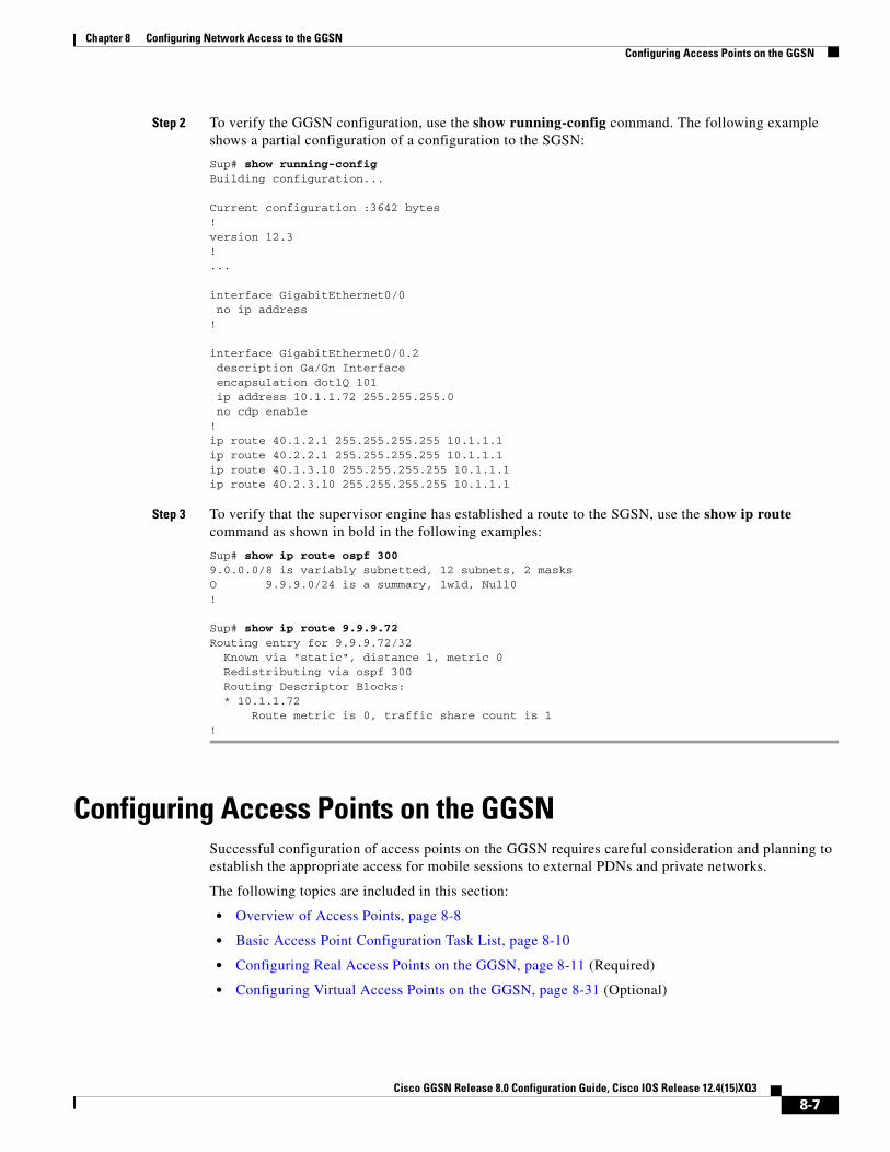
Chapter 8 Configuring Network Access to the GGSNConfiguring Access Points on the GGSN
Step 2 To verify the GGSN configuration, use the show running-config command. The following example shows a partial configuration of a configuration to the SGSN:
Sup# show running-configBuilding configuration...
Current configuration :3642 bytes!version 12.3!...
interface GigabitEthernet0/0 no ip address!
interface GigabitEthernet0/0.2 description Ga/Gn Interface encapsulation dot1Q 101 ip address 10.1.1.72 255.255.255.0 no cdp enable!ip route 40.1.2.1 255.255.255.255 10.1.1.1ip route 40.2.2.1 255.255.255.255 10.1.1.1ip route 40.1.3.10 255.255.255.255 10.1.1.1ip route 40.2.3.10 255.255.255.255 10.1.1.1
Step 3 To verify that the supervisor engine has established a route to the SGSN, use the show ip route command as shown in bold in the following examples:
Sup# show ip route ospf 3009.0.0.0/8 is variably subnetted, 12 subnets, 2 masksO 9.9.9.0/24 is a summary, 1w1d, Null0!
Sup# show ip route 9.9.9.72Routing entry for 9.9.9.72/32 Known via "static", distance 1, metric 0 Redistributing via ospf 300 Routing Descriptor Blocks: * 10.1.1.72 Route metric is 0, traffic share count is 1!
Configuring Access Points on the GGSNSuccessful configuration of access points on the GGSN requires careful consideration and planning to establish the appropriate access for mobile sessions to external PDNs and private networks.
The following topics are included in this section:
• Overview of Access Points, page 8-8
• Basic Access Point Configuration Task List, page 8-10
• Configuring Real Access Points on the GGSN, page 8-11 (Required)
• Configuring Virtual Access Points on the GGSN, page 8-31 (Optional)
8-7Cisco GGSN Release 8.0 Configuration Guide, Cisco IOS Release 12.4(15)XQ3

Chapter 8 Configuring Network Access to the GGSNConfiguring Access Points on the GGSN
Configuration of access points on the GGSN also requires properly establishing communication with any supporting DHCP and RADIUS servers that you might be using to provide dynamic IP addressing and user authentication functions at the access point.
Details about configuring other services such as DHCP and RADIUS on an access point are discussed in the “Configuring Dynamic Addressing on the GGSN” and “Configuring Security on the GGSN” chapters.
Overview of Access PointsThis section includes the following topics:
• Description of Access Points in a GPRS/UMTS Network, page 8-8
• Access Point Implementation on the Cisco GGSN, page 8-9
Description of Access Points in a GPRS/UMTS Network
The GPRS and UMTS standards define a network identity called an access point name (APN). An APN identifies the part of the network where a user session is established. In the GPRS/UMTS backbone, the APN serves as a reference to a GGSN. An APN is configured on and accessible from a GGSN in a GPRS/UMTS network.
An APN can provide access to a public data network (PDN), or a private or corporate network. An APN also can be associated with certain types of services such as Internet access or a Wireless Application Protocol (WAP) service.
The APN is provided by either the mobile station (MS) or by the SGSN to the GGSN in a Create PDP Context request message when a user requests a session to be established.
To identify an APN, a logical name is defined that consists of two parts:
• Network ID—A mandatory part of the APN that identifies the external network to which a GGSN is connected. The network ID can be a maximum of 63 bytes and must contain at least one label. A network ID of more than one label is interpreted as an Internet domain name. An example of a network ID might be “corporate.com.”
• Operator ID—An optional part of the APN that identifies the public land mobile network (PLMN) in which a GGSN is located. The operator ID contains three decimal-separated labels; the last label must be “gprs.” An example of an operator ID might be “mnc10.mcc200.gprs.”
When the operator ID exists, it is placed after the network ID, and it corresponds to the Domain Name System (DNS) name of a GGSN. The maximum length of an APN is 100 bytes. When the operator ID does not exist, a default operator ID is derived from the mobile network code (MNC) and mobile country code (MCC) information contained in the international mobile subscriber identity (IMSI).
8-8Cisco GGSN Release 8.0 Configuration Guide, Cisco IOS Release 12.4(15)XQ3

Chapter 8 Configuring Network Access to the GGSNConfiguring Access Points on the GGSN
Access Point Implementation on the Cisco GGSN
Configuring access points is one of the central configuration tasks on the Cisco GGSN. Proper configuration of access points is essential to successful implementation of the GGSN in the GPRS/UMTS network.
To configure APNs, the Cisco GGSN software uses the following configuration elements:
• Access point list—Logical interface that is associated with the virtual template of the Cisco GGSN. The access point list contains one or more access points.
• Access point—Defines an APN and its associated access characteristics, including security and method of dynamic addressing. An access point on the Cisco GGSN can be a virtual or real access point.
• Access point index number—Integer assigned to an APN that identifies the APN within the GGSN configuration. Several GGSN configuration commands use the index number to reference an APN.
• Access group—An additional level of router security on the router that is configured at an access point to control access to and from a PDN. When an MS is permitted access to the GGSN as defined by a traditional IP access list, the IP access group further defines whether access is permitted to the PDN (at the access point). The IP access group configuration can also define whether access from a PDN to an MS is permitted.
Access Point Types on the GGSN
Cisco IOS GGSN Release 3.0 and later support the following access point types:
• Real—Uses real access point types to configure the GGSN for direct access to a particular target network through an interface. The GGSN always uses real access points to reach an external network.
For information on configuring real access points on the GGSN, see the “Configuring Real Access Points on the GGSN” section on page 8-11.
• Virtual—Uses virtual access point types to consolidate access to multiple target networks through a virtual APN access point at the GGSN. Because the GGSN always uses real access points to reach an external network, virtual access points should be used in combination with real access points on the GGSN.
For information on configuring virtual access points on the GGSN, see the “Configuring Virtual Access Points on the GGSN” section on page 8-31.
Note GGSN Release 1.4 and earlier only support real access points. To address provisioning issues in the PLMN, GGSN Release 3.0 and later support virtual access point types. Additionally, with GGSN Release 6.0, Cisco IOS Release 12.3(14)YU and later, you can configure virtual APNs to be dynamically mapped, per user, to the target APN during a “pre-authentication” phase. For more information, see the “Configuring Virtual Access Points on the GGSN” section on page 8-31.
8-9Cisco GGSN Release 8.0 Configuration Guide, Cisco IOS Release 12.4(15)XQ3

Chapter 8 Configuring Network Access to the GGSNConfiguring Access Points on the GGSN
Basic Access Point Configuration Task ListThis section describes the basic tasks that are required to configure an access point on the GGSN. Detailed information about configuring access points for specialized functions such as for virtual APN access are described in separate sections of this chapter.
To configure an access point on the GGSN, perform the following basic tasks:
• Configuring the GPRS Access Point List on the GGSN, page 8-10 (Required)
• Creating an Access Point and Specifying Its Type on the GGSN, page 8-10 (Required)
Configuring the GPRS Access Point List on the GGSN
The GGSN software requires that you configure an entity called an access point list. You configure the GPRS access point list to define a collection of virtual and real access points on the GGSN.
When you configure the access point list in global configuration mode, the GGSN software automatically associates the access point list with the virtual template interface of the GGSN. Therefore, the GGSN supports only a single access point list.
Note Be careful to observe that the GPRS/UMTS access point list and an IP access list are different entities in the Cisco IOS software. A GPRS/UMTS access point list defines access points and their associated characteristics, and an IP access list controls the allowable access on the router by IP address. You can define permissions to an access point by configuring both an IP access list in global configuration and configuring the ip-access-group command in your access point configuration.
To configure the GPRS/UMTS access point list and configure access points within it, use the following command, beginning in global configuration mode:
Creating an Access Point and Specifying Its Type on the GGSN
You need to define access points within an access point list on the GGSN. Therefore, before you can create an access point, you must define a new access point list or specify the existing access point list on the GGSN to enter access-point list configuration mode.
When you create an access point, you must assign an index number to the access point, specify the domain name (network ID) of the access point, and specify the type of access point (virtual or real). Other options that you can configure on an access point are summarized in the “Configuring Additional Real Access Point Options” section on page 8-20.
Command PurposeRouter(config)# gprs access-point-list list-name Specifies a name for a new access point list, or references the
name of the existing access point list, and enters access-point list configuration mode.
8-10Cisco GGSN Release 8.0 Configuration Guide, Cisco IOS Release 12.4(15)XQ3

Chapter 8 Configuring Network Access to the GGSNConfiguring Access Points on the GGSN
To create an access point and specify its type, use the following commands, beginning in global configuration mode:
Configuring Real Access Points on the GGSNThe GGSN uses real access points to communicate to PDNs or private networks that are available over a Gi interface on the GGSN. Use real access point types to configure the GGSN for direct access to a particular target network through an interface.
If you have configured a virtual access point, you must also configure real access points to reach the target networks.
The GGSN supports configuration of access points to public data networks and to private networks. The following sections describe how to configure different types of real access points:
• PDN Access Configuration Task List, page 8-12
• VPN Access Using VRF Configuration Task Lists, page 8-13
Command Purpose
Step 1 Router(config)# gprs access-point-list list-name Specifies a name for a new access point list, or references the name of the existing access point list, and enters access-point list configuration mode.
Step 2 Router(config-ap-list)# access-point access-point-index
Specifies an index number for a new access point definition, or references an existing access point definition, and enters access point configuration mode.
Step 3 Router(config-access-point)# access-point-name apn-name
Specifies the network (or domain) name for a PDN that users can access from the GGSN at a defined access point.
Note The apn-name must match the APN that has been provisioned at the MS, home location register (HLR), and DNS server.
Step 4 Router (config-access-point)# access-type {virtual [pre-authenticate [default-apn apn-name]]| real}
(Optional) Specifies the type of access point. The available options are:
• virtual—APN type that is not associated with any specific physical target network on the GGSN. Optionally, can be configured to be dynamically mapped, per user, to a target APN.
• real—APN type that corresponds to an interface to an external network on the GGSN. This is the default value.
Note The default access-type is real. Therefore, you only need to configure this command if the APN needs to be a virtual access point.
8-11Cisco GGSN Release 8.0 Configuration Guide, Cisco IOS Release 12.4(15)XQ3

Chapter 8 Configuring Network Access to the GGSNConfiguring Access Points on the GGSN
PDN Access Configuration Task List
Configuring a connection to a public PDN includes the following tasks:
• Configuring an Interface to a PDN (Gi interface) (Required)
• Configuring an Access Point for a PDN (Required)
Configuring an Interface to a PDN
To establish access to a PDN in the GPRS/UMTS network, you must configure an interface on the GGSN to connect to the PDN. This interface is referred to as the Gi interface.
On the Cisco 7600 series router platform, this interface is a logical one (on which IEEE 802.1Q encapsulation has been configured) to a Layer 3 routed Gi VLAN configured on the supervisor engine.
For more information about the Gi VLAN on the supervisor engine, see “Platform Prerequisites” section on page 2-2.
For more information about configuring interfaces, see the Cisco IOS Interface Configuration Guide and the Cisco IOS Interface Command Reference.
Note If you are using VPN routing and forwarding (VRF) for VPN access, you must enable Cisco Express Forwarding (CEF) switching on the GGSN. If you enable CEF switching at the global configuration level, then it is automatically enabled for each interface unless it has been specifically disabled at the interface.
Configuring 802.1Q-Encapsulated Subinterfaces
To configure a subinterface that supports IEEE 802.1Q encapsulation to the Gi VLAN, use the following commands, beginning in global configuration mode:
Command Purpose
Step 1 Router(config)# interface gigabitethernet slot/port.subinterface-number
Specifies the subinterface on which IEEE 802.1Q will be used.
Step 2 Router(config-if)# encapsulation dot1q vlanid Defines the encapsulation format as IEEE 802.1Q (dot1q), and specifies the VLAN identifier.
Step 3 Router(config-if)# ip address ip-address mask Sets a primary IP address for an interface.
8-12Cisco GGSN Release 8.0 Configuration Guide, Cisco IOS Release 12.4(15)XQ3

Chapter 8 Configuring Network Access to the GGSNConfiguring Access Points on the GGSN
Configuring an Access Point for a PDN
To configure an access point for a PDN, you must define a real access point in the GPRS access point list.
To configure a real access point on the GGSN, use the following commands, beginning in global configuration mode:
For an example of a GPRS access point configuration, see the “Access Point List Configuration Example” section on page 8-51.
VPN Access Using VRF Configuration Task Lists
The Cisco IOS GGSN software supports connectivity to a VPN using VPN routing and forwarding (VRF).
Note VRF is not supported for IPv6 PDPs. Therefore, if the ipv6 command is configured on an APN on which VRF is enabled, the IPv4 PDPs are routed in VRF, but the IPv6 PDPs are routed in the global routing table.
The GGSN software provides a couple of ways that you can configure access to a VPN, depending on your platform, network configuration over the Gi interface between the GGSN and your PDNs, and the VPN that you want to access.
To configure VPN access using VRF on the GGSN, perform the following tasks:
• Enabling CEF Switching, page 8-14 (Required)
• Configuring a VRF Routing Table on the GGSN, page 8-14 (Required)
• Configuring a Route to the VPN Using VRF, page 8-14 (Required)
• Configuring an Interface to a PDN Using VRF, page 8-16 (Required)
• Configuring Access to a VPN, page 8-17 (Required)
For sample configurations, see the “VRF Tunnel Configuration Example” section on page 8-52.
Command Purpose
Step 1 Router(config)# gprs access-point-list list-name Specifies a name for a new access-point list, or references the name of an existing access-point list, and enters access-point list configuration mode.
Step 2 Router(config-ap-list)# access-point access-point-index
Specifies an index number for a new access point definition, or references an existing access point definition, and enters access point configuration mode.
Step 3 Router(config-access-point)# access-point-name apn-name
Specifies the network (or domain) name for a PDN that users can access from the GGSN at a defined access point.
Note The apn-name must match the APN that has been provisioned at the MS, HLR, and DNS server.
Step 4 Router(config-access-point)# access-type real Specifies an APN type that corresponds to an interface to an external network on the GGSN. Real is the default value.
8-13Cisco GGSN Release 8.0 Configuration Guide, Cisco IOS Release 12.4(15)XQ3

Chapter 8 Configuring Network Access to the GGSNConfiguring Access Points on the GGSN
Enabling CEF Switching
When you enable CEF switching globally on the GGSN, all interfaces on the GGSN are automatically enabled for CEF switching.
Note To ensure that CEF switching functions properly, wait a short time before enabling CEF switching after it has been disabled using the no ip cef command.
To enable CEF switching for all interfaces on the GGSN, use the following commands, beginning in global configuration mode:
Configuring a VRF Routing Table on the GGSN
To configure a VRF routing table on the GGSN, use the following commands, beginning in global configuration mode:
Configuring a Route to the VPN Using VRF
Be sure that a route exists between the GGSN and the private network that you want to access. You can verify connectivity by using the ping command from the GGSN to the private network address. To configure a route, you can use a static route or a routing protocol.
Command Purpose
Router(config)# ip cef Enables CEF on the processor.
Command Purpose
Step 1 Router(config)# ip vrf vrf-name Configures a VRF routing table, and enters VRF configuration mode.
Step 2 Router(config-vrf)# rd route-distinguisher Creates routing and forwarding tables for a VRF and specifies the default route distinguisher for a VPN.
8-14Cisco GGSN Release 8.0 Configuration Guide, Cisco IOS Release 12.4(15)XQ3

Chapter 8 Configuring Network Access to the GGSNConfiguring Access Points on the GGSN
Configuring a Static Route Using VRF
To configure a static route using VRF, use the following command, beginning in global configuration mode:
Verifying a Static Route Using VRF
To verify that the GGSN has established the static VRF route that you configured, use the show ip route vrf privileged EXEC command as shown in the following example:
GGSN# show ip route vrf vpn1 static 172.16.0.0/32 is subnetted, 1 subnetsU 172.16.0.1 [1/0] via 0.0.0.0, Virtual-Access2 10.0.0.0/8 is variably subnetted, 2 subnets, 2 masksS 10.100.0.3/32 [1/0] via 10.110.0.13
Command PurposeRouter(config)# ip route vrf vrf-name prefix mask [next-hop-address] [interface {interface-number}] [global] [distance] [permanent] [tag tag]
Configures a static IP route, where:
• vrf-name—Specifies the name of the VPN routing/forwarding instance (VRF) for the static route.
• prefix—Specifies the IP route prefix for the destination.
• mask—Specifies the prefix mask for the destination.
• next-hop-address—Specifies the IP address of the next hop that can be used to reach the destination network.
• interface interface-number—Specifies the network interface type and interface number that can be used to reach the destination network.
• global—Specifies that the given next hop address is in the non-VRF routing table.
• distance—Specifies an administrative distance for the route.
• permanent—Specifies that the route will not be removed, even if the interface shuts down.
• tag tag—Specifies a tag value that can be used as a “match” value for controlling redistribution via route maps.
8-15Cisco GGSN Release 8.0 Configuration Guide, Cisco IOS Release 12.4(15)XQ3

Chapter 8 Configuring Network Access to the GGSNConfiguring Access Points on the GGSN
Configuring an OSPF Route Using VRF
To configure an OSPF route using VRF, use the following command, beginning in global configuration mode:
Configuring an Interface to a PDN Using VRF
To establish access to a PDN, an interface on the GGSN to connect to the PDN. This interface is referred to as the Gi interface.
On the Cisco 7600 series router platform, this interface is a logical one (on which IEEE 802.1Q encapsulation has been configured) to a Layer 3 routed Gi VLAN configured on the supervisor engine.
For more information about the Gi VLAN on the supervisor engine, see “Platform Prerequisites” section on page 2-2.
For more information about configuring interfaces, see the Cisco IOS Interface Configuration Guide and the Cisco IOS Interface Command Reference.
Note If you are using VRF for VPN access, you must enable CEF switching on the GGSN. If you enable CEF switching at the global configuration level, then it is automatically enabled for each interface unless it has been specifically disabled at the interface.
Configuring 802.1Q-Encapsulated Subinterfaces
To configure a subinterface that supports IEEE 802.1Q encapsulation to the Gi VLAN, use the following commands, beginning in global configuration mode:
Command PurposeRouter(config)# router ospf process-id [vrf vrf-name] Enables OSPF routing, and enters router configuration mode,
where,
• process-id—Specifies an internally used identification parameter for an OSPF routing process. The process-id is locally assigned and can be any positive integer. A unique value is assigned for each OSPF routing process.
• vrf vrf-name—Specifies the name of the VPN routing/forwarding instance.
Command Purpose
Step 1 Router(config)# interface gigabitethernet slot/port.subinterface-number
Specifies the subinterface on which IEEE 802.1Q will be used.
Step 2 Router(config-if)# encapsulation dot1q vlanid Defines the encapsulation format as IEEE 802.1Q (dot1q), and specifies the VLAN identifier.
Step 3 Router(config-if)# ip address ip-address mask Sets a primary IP address for an interface.
8-16Cisco GGSN Release 8.0 Configuration Guide, Cisco IOS Release 12.4(15)XQ3

Chapter 8 Configuring Network Access to the GGSNConfiguring Access Points on the GGSN
Configuring Access to a VPN
After you have completed the prerequisite configuration tasks, you can configure access to a VPN with a tunnel or without a tunnel.
The following sections describe the different methods you can use to configure access to a VPN:
Configuring Access to a VPN Without a Tunnel
Configuring Access to a VPN With a Tunnel
Note With GGSN Release 5.0 and later, you can assign multiple APNs to the same VRF.
Configuring Access to a VPN Without a Tunnel
If you configure more than one Gi interface to different PDNs, and need to access a VPN off one of those PDNs, then you can configure access to that VPN without configuring an IP tunnel. To configure access to the VPN in this case, you need to configure the vrf access point configuration command.
To configure access to a VPN in the GPRS access point list, use the following commands, beginning in global configuration mode:
For information about the other access point configuration options, see the “Configuring Additional Real Access Point Options” section on page 8-20.
Command Purpose
Step 1 Router(config)# gprs access-point-list list-name Specifies a name for a new access point list, or references the name of the existing access point list, and enters access-point list configuration mode.
Step 2 Router(config-ap-list)# access-point access-point-index
Specifies an index number for a new access point definition, or references an existing access point definition, and enters access point configuration mode.
Step 3 Router(config-access-point)# access-point-name apn-name
Specifies the network (or domain) name for a PDN that users can access from the GGSN at a defined access point.
Note The apn-name must match the APN that has been provisioned at the MS, HLR, and Domain Name System (DNS) server.
Step 4 Router(config-access-point)# access-type real Specifies an APN type that corresponds to an interface to an external network on the GGSN. Real is the default value.
Step 5 Router(config-access-point)# vrf vrf-name Configures VRF at a GGSN access point and associates the access point with a particular VRF instance.
Step 6 Router(config-access-point)# exit Exits access point configuration mode.
8-17Cisco GGSN Release 8.0 Configuration Guide, Cisco IOS Release 12.4(15)XQ3
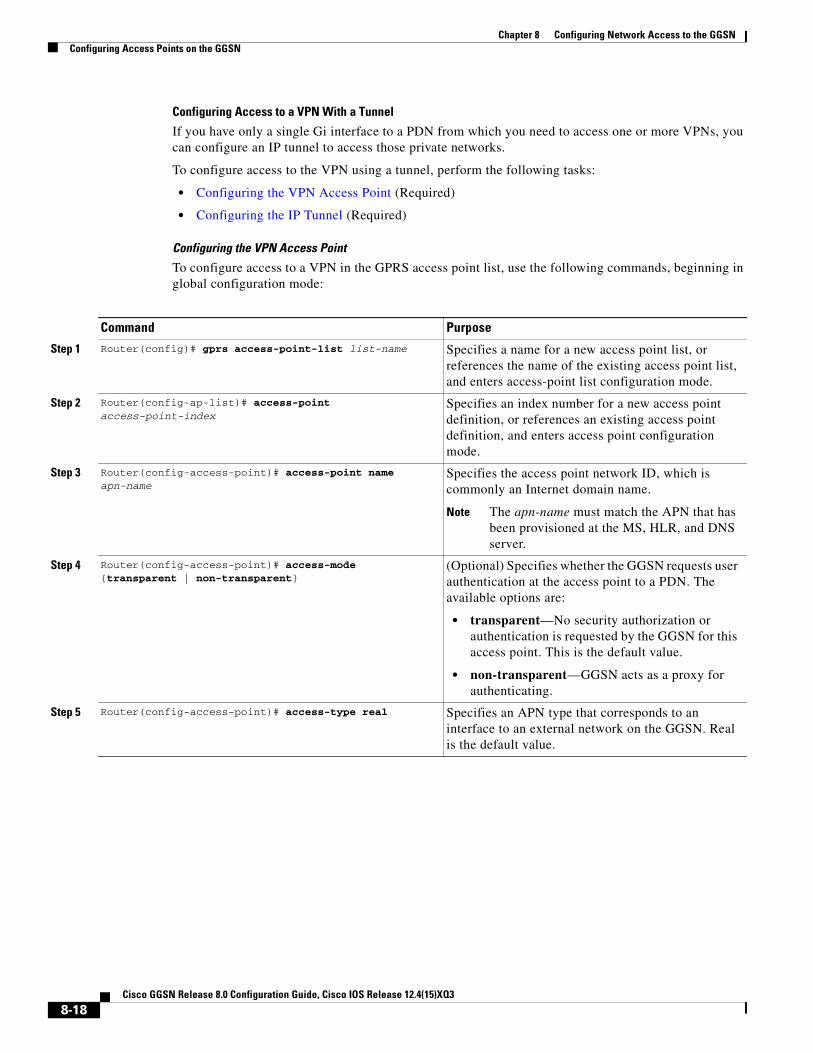
Chapter 8 Configuring Network Access to the GGSNConfiguring Access Points on the GGSN
Configuring Access to a VPN With a Tunnel
If you have only a single Gi interface to a PDN from which you need to access one or more VPNs, you can configure an IP tunnel to access those private networks.
To configure access to the VPN using a tunnel, perform the following tasks:
• Configuring the VPN Access Point (Required)
• Configuring the IP Tunnel (Required)
Configuring the VPN Access PointTo configure access to a VPN in the GPRS access point list, use the following commands, beginning in global configuration mode:
Command Purpose
Step 1 Router(config)# gprs access-point-list list-name Specifies a name for a new access point list, or references the name of the existing access point list, and enters access-point list configuration mode.
Step 2 Router(config-ap-list)# access-point access-point-index
Specifies an index number for a new access point definition, or references an existing access point definition, and enters access point configuration mode.
Step 3 Router(config-access-point)# access-point name apn-name
Specifies the access point network ID, which is commonly an Internet domain name.
Note The apn-name must match the APN that has been provisioned at the MS, HLR, and DNS server.
Step 4 Router(config-access-point)# access-mode {transparent | non-transparent}
(Optional) Specifies whether the GGSN requests user authentication at the access point to a PDN. The available options are:
• transparent—No security authorization or authentication is requested by the GGSN for this access point. This is the default value.
• non-transparent—GGSN acts as a proxy for authenticating.
Step 5 Router(config-access-point)# access-type real Specifies an APN type that corresponds to an interface to an external network on the GGSN. Real is the default value.
8-18Cisco GGSN Release 8.0 Configuration Guide, Cisco IOS Release 12.4(15)XQ3

Chapter 8 Configuring Network Access to the GGSNConfiguring Access Points on the GGSN
For information about the other access point configuration options, see the “Configuring Additional Real Access Point Options” section on page 8-20.
Configuring the IP TunnelWhen you configure a tunnel, you might consider using loopback interfaces as the tunnel endpoints instead of real interfaces because loopback interfaces are always up.
To configure an IP tunnel to a private network, use the following commands, beginning in global configuration mode:
Step 6 Router(config-access-point)# ip-address-pool {dhcp-proxy-client | radius-client | local pool-name | disable}
(Optional) Specifies a dynamic address allocation method using IP address pools for the current access point. The available options are:
• dhcp-proxy-client—DHCP server provides the IP address pool.
• radius-client—RADIUS server provides the IP address pool.
• local—Specifies that a local pool provides the IP address. This option requires configuration of a local pool using the ip local pool global configuration command.
• disable—Turns off dynamic address allocation.
Note If you are using a dynamic address allocation method, then you must configure this command according to the appropriate IP address pool source.
Step 7 Router(config-access-point)# vrf vrf-name Configures VPN routing and forwarding at a GGSN access point and associates the access point with a particular VRF instance.
Step 8 Router(config-access-point)# exit Exits access point configuration mode.
Command Purpose
Command Purpose
Step 1 Router(config)# interface tunnel number Configures a logical tunnel interface number.
Step 2 Router(config-if)# ip vrf forwarding vrf-name Associates a VRF instance with the interface.
Step 3 Router(config-if)# ip address ip-address mask [secondary]
Specifies an IP address for the tunnel interface.
Note This IP address is not used in any other part of the GGSN configuration.
Step 4 Router(config-if)# tunnel source {ip-address | type number}
Specifies the IP address (or interface type and port or card number) of the Gi interface to the PDN or a loopback interface.
Step 5 Router(config-if)# tunnel destination {hostname | ip-address}
Specifies IP address (or host name) of the private network that you can access from this tunnel.
8-19Cisco GGSN Release 8.0 Configuration Guide, Cisco IOS Release 12.4(15)XQ3

Chapter 8 Configuring Network Access to the GGSNConfiguring Access Points on the GGSN
Configuring Additional Real Access Point Options
This section summarizes the configuration options that you can specify for a GGSN access point.
Some of these options are used in combination with other global router settings to configure the GGSN. Further details about configuring several of these options are discussed in other topics in this chapter and other chapters of this book.
Note Although the Cisco IOS software allows you to configure other access point options on a virtual access point, only the access-point-name and access-type commands are applicable to a virtual access point. Other access point configuration commands, if configured, will be ignored.
To configure options for a GGSN access point, use any of the following commands, beginning in access- point list configuration mode:
Command Purpose
Step 1 Router(config-access-point)# aaa-accounting {enable | disable}
Enables or disables accounting for a particular access point on the GGSN.
Note If you have configured a transparent access APN and you want to provide accounting at that APN, you need to configure the aaa-accounting enable command at the APN.
Step 2 Router(config-access-point)# aaa-group {authentication | accounting} server-group
Specifies a default authentication, authorization, and accounting (AAA) server group and assigns the type of AAA services to be supported by the server group for a particular access point on the GGSN, where:
• authentication—Assigns the selected server group for authentication services on the APN.
• accounting—Assigns the selected server group for accounting services on the APN.
• server-group—Specifies the name of an AAA server group to be used for AAA services on the APN.
Note The name of the AAA server group that you specify must correspond to a server group that you configure using the aaa group server command.
Step 3 Router(config-access-point)# access-mode {transparent | non-transparent}
(Optional) Specifies whether the GGSN requests user authentication at the access point to a PDN. The available options are:
• transparent—No security authorization or authentication is requested by the GGSN for this access point. This is the default value.
• non-transparent—GGSN acts as a proxy for authenticating.
8-20Cisco GGSN Release 8.0 Configuration Guide, Cisco IOS Release 12.4(15)XQ3

Chapter 8 Configuring Network Access to the GGSNConfiguring Access Points on the GGSN
Step 1 Router(config-ap-list)# access-point access-point-index
Specifies an index number for a new access point definition, or references an existing access point definition, and enters access point configuration mode.
Step 2 Router(config-access-point)# access-point-name apn-name
Specifies the network (or domain) name for a PDN that users can access from the GGSN at a defined access point.
Note The apn-name must match the APN that has been provisioned at the MS, HLR, and DNS server.
Step 3 Router(config-access-point)# access-type {virtual | real}
(Optional) Specifies the type of access point. The available options are:
• virtual—APN type that is not associated with any specific physical target network.
• real—APN type that corresponds to an interface to an external network on the GGSN. This is the default value.
Note The default access-type is real. Therefore, you only need to configure this command if the APN needs to be a virtual access point.
Step 4 Router(config-access-point)# access-violation deactivate-pdp-context}
(Optional) Specifies that a user’s session be ended and the user packets discarded when a user attempts unauthorized access to a PDN through an access point.
Step 5 Router(config-access-point)# aggregate {auto | ip-network-prefix{/mask-bit-length | ip-mask}}
(Optional) Configures the GGSN to create an aggregate route in its IP routing table when receiving PDP requests from MSs on the specified network through a particular access point on the GGSN.
Note The aggregate auto command will not aggregate routes when using local IP address pools.
Note This configuration applies to IPv4 PDP contexts.
Step 6 Router(config-access-point)# anonymous user username [password]
(Optional) Configures anonymous user access at an access point.
Step 7 Router(config-access-point)# block-foreign-ms (Optional) Restricts GGSN access at a particular access point based on the mobile user’s home PLMN.
Step 8 Router(config-access-point)# cac-policy (Optional) Enables the maximum QoS policy function of the Call Admission Control (CAC) feature and applies a policy to an access point.
Step 9 Router(config-access-point)# dhcp-gateway-address ip-address
(Optional) Specifies a DHCP gateway to handle DHCP requests for mobile station (MS) users entering a particular PDN access point.
Note This configuration applies to IPv4 PDP contexts.
Command Purpose
8-21Cisco GGSN Release 8.0 Configuration Guide, Cisco IOS Release 12.4(15)XQ3

Chapter 8 Configuring Network Access to the GGSNConfiguring Access Points on the GGSN
Step 10 Router(config-access-point)# dhcp-server {ip-address} [ip-address] [vrf]
(Optional) Specifies a primary (and backup) DHCP server to allocate IP addresses to MS users entering a particular PDN access point.
Note This configuration applies to IPv4 PDP contexts.
Step 11 Router(config-access-point)# dns primary ip-address secondary ip-address
(Optional) Specifies a primary (and backup) DNS to be sent in Create PDP Context responses at the access point.
Note This configuration applies to IPv4 PDP contexts.
Step 12 Router(config-access-point)# gtp pdp-context single pdp-session [mandatory]
(Optional) Configures the GGSN to delete the primary PDP context, and any associated secondary PDP contexts, of a hanging PDP session upon receiving a new create request from the same MS that shares the same IP address of the hanging PDP context.
A hanging PDP context is a PDP context on the GGSN whose corresponding PDP context on the SGSN has already been deleted for some reason.
When a hanging PDP session occurs and the gtp pdp-context single pdp-session command is not configured, if the same MS (on the same APN) sends a new Create PDP Context request that has a different NSAPI but has been assigned the same IP address used by the hanging PDP session, the GGSN rejects the new Create PDP Context request.
When configure without the mandatory keyword specified, this feature applies only to those users for whom the Cisco vendor-specific attribute (VSA) “gtp-pdp-session=single-session” has been defined in their RADIUS user profile.
To enable this feature and apply it to all users on an APN regardless of their RADIUS user profiles, specify the mandatory keyword option.
Note If this feature is used with GTP load balancing, it might not function properly.
Note This configuration applies to IPv4 PDP contexts.
Step 13 Router(config-access-point)# gtp response-message wait-accounting
(Optional) Configures the GGSN to wait for a RADIUS accounting response before sending a Create PDP Context response to the SGSN.
Step 14 Router(config-access-point)# gtp pdp-context timeout idle interval [uplink]
(Optional) Specifies the time, in seconds, that a GGSN allows a session to be idle at a particular access point before terminating the session.
Command Purpose
8-22Cisco GGSN Release 8.0 Configuration Guide, Cisco IOS Release 12.4(15)XQ3

Chapter 8 Configuring Network Access to the GGSNConfiguring Access Points on the GGSN
Step 15 Router(config-access-point)# gtp pdp-context timeout session interval [uplink]
(Optional) Specifies the time, in seconds, that the GGSN allows a session to exist at any access point before terminating the session.
Step 16 Router(config-access-point)# ip-access-group access-list-number {in | out}
(Optional) Specifies access permissions between an MS and a PDN through the GGSN at a particular access point, where access-list-number specifies the IP access list definition to be used at the access point. The available options are:
• in—Applies the IP access list definition from the PDN to the MS.
• out—Applies the IP access list definition from the MS to the PDN.
Note To disable the sending of ICMP messages, ensure that the no ip unreachable interface configuration command has been configured on the virtual template interface.
Note This configuration applies to IPv4 PDP contexts.
Step 17 Router(config-access-point)# ip-address-pool {dhcp-proxy-client | radius-client | local pool-name | disable}
(Optional) Specifies a dynamic address allocation method using IP address pools for the current access point. The available options are:
• dhcp-proxy-client—DHCP server provides the IP address pool.
• radius-client—RADIUS server provides the IP address pool.
• local—Specifies that a local pool provides the IP address. This option requires that a local pool has been configured using the ip local pool global configuration command.
• disable—Turns off dynamic address allocation.
Note If you are using a dynamic address allocation method, then you must configure this command according to the appropriate IP address pool source.
Note This configuration applies to IPv4 PDP contexts.
Step 18 Router(config-access-point)# ip probe path ip_address protocol udp [port port ttl ttl]
(Optional) Enables the GGSN to send a probe packet to a specific destination for each PDP context that is successfully established on an APN.
Note This configuration applies to IPv4 PDP contexts.
Step 19 Router(config-access-point)# ipv6 ipv6-access-group ACL-name [up | down]
(Optional) Applies an access-control list (ACL) configuration to uplink or downlink IPv6 payload packets.
Command Purpose
8-23Cisco GGSN Release 8.0 Configuration Guide, Cisco IOS Release 12.4(15)XQ3
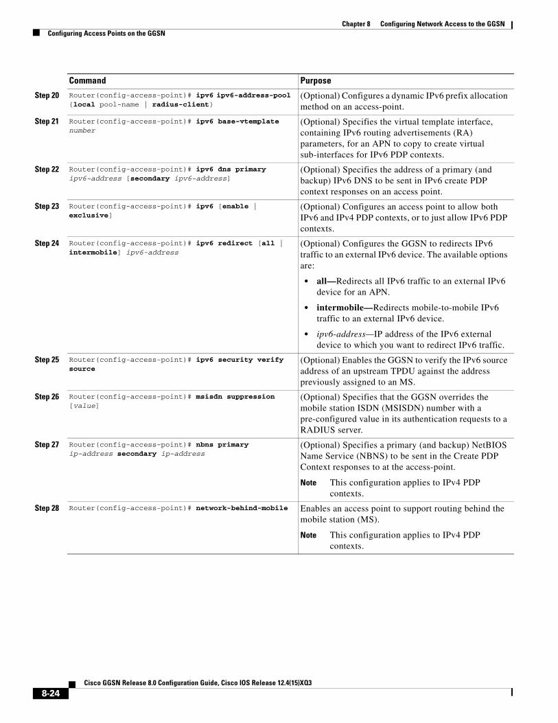
Chapter 8 Configuring Network Access to the GGSNConfiguring Access Points on the GGSN
Step 20 Router(config-access-point)# ipv6 ipv6-address-pool {local pool-name | radius-client}
(Optional) Configures a dynamic IPv6 prefix allocation method on an access-point.
Step 21 Router(config-access-point)# ipv6 base-vtemplate number
(Optional) Specifies the virtual template interface, containing IPv6 routing advertisements (RA) parameters, for an APN to copy to create virtual sub-interfaces for IPv6 PDP contexts.
Step 22 Router(config-access-point)# ipv6 dns primary ipv6-address [secondary ipv6-address]
(Optional) Specifies the address of a primary (and backup) IPv6 DNS to be sent in IPv6 create PDP context responses on an access point.
Step 23 Router(config-access-point)# ipv6 [enable | exclusive]
(Optional) Configures an access point to allow both IPv6 and IPv4 PDP contexts, or to just allow IPv6 PDP contexts.
Step 24 Router(config-access-point)# ipv6 redirect [all | intermobile] ipv6-address
(Optional) Configures the GGSN to redirects IPv6 traffic to an external IPv6 device. The available options are:
• all—Redirects all IPv6 traffic to an external IPv6 device for an APN.
• intermobile—Redirects mobile-to-mobile IPv6 traffic to an external IPv6 device.
• ipv6-address—IP address of the IPv6 external device to which you want to redirect IPv6 traffic.
Step 25 Router(config-access-point)# ipv6 security verify source
(Optional) Enables the GGSN to verify the IPv6 source address of an upstream TPDU against the address previously assigned to an MS.
Step 26 Router(config-access-point)# msisdn suppression [value]
(Optional) Specifies that the GGSN overrides the mobile station ISDN (MSISDN) number with a pre-configured value in its authentication requests to a RADIUS server.
Step 27 Router(config-access-point)# nbns primary ip-address secondary ip-address
(Optional) Specifies a primary (and backup) NetBIOS Name Service (NBNS) to be sent in the Create PDP Context responses to at the access-point.
Note This configuration applies to IPv4 PDP contexts.
Step 28 Router(config-access-point)# network-behind-mobile Enables an access point to support routing behind the mobile station (MS).
Note This configuration applies to IPv4 PDP contexts.
Command Purpose
8-24Cisco GGSN Release 8.0 Configuration Guide, Cisco IOS Release 12.4(15)XQ3

Chapter 8 Configuring Network Access to the GGSNConfiguring Access Points on the GGSN
Step 29 Router(config-access-point)# ppp-regeneration [max-session number | setup-time seconds | verify-domain | fixed-domain | allow-duplicate]
(Optional) Enables an access point to support PPP regeneration, where:
• max-session number—Specifies the maximum number of PPP regenerated sessions allowed at the access point. The default value is device dependent and is determined by the maximum number of IDBs that can be supported by the router.
• setup-time seconds—Specifies the maximum amount of time (between 1 and 65535 seconds) within which a PPP regenerated session must be established. The default value is 60 seconds.
• verify-domain—Configures the GGSN to verify the domain sent in the protocol configuration option (PCO) IE sent in a Create PDP Context request against the APN sent out by the user when PPP-regeneration is being used.
If a mismatch occurs, the Create PDP Context request is rejected with the cause code “Service not supported.”
• fixed-domain—Configures the GGSN to use the access point name as the domain name with which it initiates an L2TP tunnel to the user when PPP-regeneration is being used.
The ppp-regeneration fixed-domain and ppp-regeneration verify-domain command configurations are mutually exclusive. When the ppp-regeneration fixed-domain command is configured, domain verification cannot be performed.
• allow-duplicate—Configures the GGSN to not check for duplicate IP addresses for PPP regenerated PDP contexts.
Note This configuration applies to IPv4 PDP contexts.
Step 30 Router(config-access-point)# radius attribute acct-session-id charging-id
(Optional) Specifies that the charging ID in the Acct-Session-ID (attribute 44) is included in access requests.
Step 31 Router(config-access-point)# radius attribute nas-id format
(Optional) Specifies that the GGSN sends the NAS-Identifier in access requests at the APN where format is a string sent in attribute 32 containing an IP address (%i), a host name (%h), and a domain name (%d).
Command Purpose
8-25Cisco GGSN Release 8.0 Configuration Guide, Cisco IOS Release 12.4(15)XQ3

Chapter 8 Configuring Network Access to the GGSNConfiguring Access Points on the GGSN
Verifying the Real Access Point Configuration
This section describes how to verify that you have successfully configured access points on the GGSN, and includes the following tasks:
• Verifying the GGSN Configuration, page 8-27
• Verifying Reachability of the Network Through the Access Point, page 8-29
Step 32 Router(config-access-point)# radius attribute suppress [imsi | qos | sgsn-address]
(Optional) Specifies that the GGSN suppress the following in its authentication and accounting requests to a RADIUS server:
• imsi—Suppresses the 3GPP-IMSI number.
• qos—Suppresses the 3GPP-GPRS-Qos Profile.
• sgsn-address—Suppresses the 3GPP-GPRS-SGSN-Address
Step 33 Router(config-access-point)# radius attribute user-name msisdn
(Optional) Specifies that the MSISDN is included in the User-Name (attribute 1) field in access requests.
Step 34 Router(config-access-point) redirect all ip ip address
(Optional) Configures the GGSN to redirect all traffic to an external device.
Note This configuration applies to IPv4 PDP contexts.
Step 35 Router(config-access-point) redirect intermobile ip ip address
(Optional) Configures the GGSN to redirect mobile-to-mobile traffic to an external device.
Note This configuration applies to IPv4 PDP contexts.
Step 36 Router(config-access-point) security verify {source | destination}
Specifies that the GGSN verify the source or destination address in Transport Protocol Data Units (TPDUs) received from a Gn interface.
Note This configuration applies to IPv4 PDP contexts.
Step 37 Router(config-access-point)# session idle-timer number
(Optional) Specifies the time (between 1 and 168 hours) that the GGSN waits before purging idle mobile sessions for the current access point.
Step 38 Router(config-access-point)# subscription-required (Optional) Specifies that the GGSN checks the value of the selection mode in a PDP context request to determine if a subscription is required to access a PDN through the access point.
Step 39 Router(config-access-point)# vrf vrf-name (Optional) Configures VPN routing and forwarding at a GGSN access point and associates the access point with a particular VRF instance.
Note This configuration applies to IPv4 PDP contexts.
Command Purpose
8-26Cisco GGSN Release 8.0 Configuration Guide, Cisco IOS Release 12.4(15)XQ3
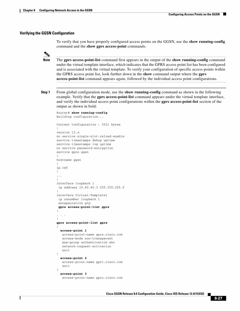
Chapter 8 Configuring Network Access to the GGSNConfiguring Access Points on the GGSN
Verifying the GGSN Configuration
To verify that you have properly configured access points on the GGSN, use the show running-config command and the show gprs access-point commands.
Note The gprs access-point-list command first appears in the output of the show running-config command under the virtual template interface, which indicates that the GPRS access point list has been configured and is associated with the virtual template. To verify your configuration of specific access points within the GPRS access point list, look further down in the show command output where the gprs access-point-list command appears again, followed by the individual access point configurations.
Step 1 From global configuration mode, use the show running-config command as shown in the following example. Verify that the gprs access-point-list command appears under the virtual template interface, and verify the individual access point configurations within the gprs access-point-list section of the output as shown in bold:
Router# show running-configBuilding configuration...
Current configuration : 3521 bytes!version 12.xno service single-slot-reload-enableservice timestamps debug uptimeservice timestamps log uptimeno service password-encryptionservice gprs ggsn!hostname ggsn!ip cef!...!interface loopback 1 ip address 10.40.40.3 255.255.255.0!interface Virtual-Template1 ip unnumber loopback 1 encapsulation gtp gprs access-point-list gprs!. . .!gprs access-point-list gprs! access-point 1 access-point-name gprs.cisco.com access-mode non-transparent aaa-group authentication abc network-request-activation exit! access-point 2 access-point-name gprt.cisco.com exit! access-point 3 access-point-name gpru.cisco.com
8-27Cisco GGSN Release 8.0 Configuration Guide, Cisco IOS Release 12.4(15)XQ3

Chapter 8 Configuring Network Access to the GGSNConfiguring Access Points on the GGSN
ip-address-pool radius-client access-mode non-transparent aaa-group authentication abc exit!gprs maximum-pdp-context-allowed 90000gprs gtp path-echo-interval 0gprs default charging-gateway 10.15.15.1!gprs memory threshold 512!...radius-server host 172.18.43.7 auth-port 1645 acct-port 1646 non-standardradius-server retransmit 3radius-server key 7 12150415call rsvp-sync!no mgcp timer receive-rtcp!mgcp profile default!gatekeeper shutdownend
Step 2 To view the configuration of a specific access point on the GGSN in further detail, use the show gprs access-point command and specify the index number of the access point, as shown in the following example:
Router# show gprs access-point 2 apn_index 2 apn_name = gprt.cisco.com apn_mode: transparent apn-type: Real accounting: Disable wait_accounting: Disable dynamic_address_pool: not configured apn_dhcp_server: 0.0.0.0 apn_dhcp_gateway_addr: 0.0.0.0 apn_authentication_server_group: apn_accounting_server_group: apn_username: , apn_password: subscribe_required: No deactivate_pdp_context_on violation: No network_activation_allowed: No Block Foreign-MS Mode: Disable VPN: Disable GPRS vaccess interface: Virtual-Access1 number of ip_address_allocated 0
Total number of PDP in this APN :1
aggregate: In APN: Disable
In Global: Disable
8-28Cisco GGSN Release 8.0 Configuration Guide, Cisco IOS Release 12.4(15)XQ3

Chapter 8 Configuring Network Access to the GGSNConfiguring Access Points on the GGSN
Step 3 To view a summary of every access point that is configured on the GGSN, use the show gprs access-point all command as shown in the following example:
Router# show gprs access-point all
There are 3 Access-Points configured
Index Mode Access-type AccessPointName VRF Name-----------------------------------------------------------------------1 non-transparent Real gprs.cisco.com -----------------------------------------------------------------------2 transparent Real gprt.cisco.com-----------------------------------------------------------------------3 non-transparent Real gpru.cisco.com-----------------------------------------------------------------------
Verifying Reachability of the Network Through the Access Point
The following procedure provides a basic methodology for verifying reachability from the MS to the destination network.
Note Many factors can affect whether you can successfully reach the destination network. Although this procedure does not attempt to fully address those factors, it is important for you to be aware that your particular configuration of the APN, IP routing, and physical connectivity of the GGSN, can affect end-to-end connectivity between a host and an MS.
To verify that you can reach the network from the MS, perform the following steps:
Step 1 From the MS (for example, using a handset), create a PDP context with the GGSN by specifying the APN to which you want to connect. In this example, you specify the APN gprt.cisco.com.
Step 2 From global configuration mode on the GGSN, use the show gprs access-point command and verify the number of created network PDP contexts (in the Total number of PDP in this APN output field).
The following example shows one successful PDP context request:
Router# show gprs access-point 2 apn_index 2 apn_name = gprt.cisco.com apn_mode: transparent apn-type: Real accounting: Disable wait_accounting: Disable dynamic_address_pool: not configured apn_dhcp_server: 0.0.0.0 apn_dhcp_gateway_addr: 0.0.0.0 apn_authentication_server_group: apn_accounting_server_group: apn_username: , apn_password: subscribe_required: No deactivate_pdp_context_on violation: Yes network_activation_allowed: No Block Foreign-MS Mode: Disable
8-29Cisco GGSN Release 8.0 Configuration Guide, Cisco IOS Release 12.4(15)XQ3

Chapter 8 Configuring Network Access to the GGSNConfiguring Access Points on the GGSN
VPN: Disable GPRS vaccess interface: Virtual-Access1 number of ip_address_allocated 0
Total number of PDP in this APN :1
aggregate: In APN: Disable
In Global: Disable
Step 3 To test further, generate traffic to the network. To do this, use the ping command from a handset, or from a laptop connected to the handset, to a host on the destination network, as shown in the following example:
ping 192.168.12.5
Note To avoid possible DNS configuration issues, use the IP address (rather than the host name) of a host that you expect to be reachable within the destination network. For this test to work, the IP address of the host that you select must be able to be properly routed by the GGSN. In addition, the APN configuration and physical connectivity to the destination network through a Gi interface must be established. For example, if the host to be reached is in a VPN, the APN must be properly configured to provide access to the VPN.
Step 4 After you have begun to generate traffic over the PDP context, use the show gprs gtp pdp-context command to see detailed statistics including send and receive byte and packet counts.
Tip To find the Terminal Identifier (TID) for a particular PDP context on an APN, use the show gprs gtp pdp-context access-point command.
The following example shows sample output for a PDP context for TID 81726354453647FA:
Router# show gprs gtp pdp-context tid 81726354453647FA
TID MS Addr Source SGSN Addr APN81726354453647FA 10.2.2.1 Static 172.16.44.1 gprt.cisco.com
current time :Dec 06 2001 13:15:34 user_name (IMSI): 18273645546374 MS address: 10.2.2.1 MS International PSTN/ISDN Number (MSISDN): 243926901 sgsn_addr_signal: 172.16.44.1 ggsn_addr_signal: 10.30.30.1 signal_sequence: 7 seq_tpdu_up: 0 seq_tpdu_down: 5380 upstream_signal_flow: 371 upstream_data_flow: 372 downstream_signal_flow: 1 downstream_data_flow: 1 RAupdate_flow: 0 pdp_create_time: Dec 06 2001 09:54:43 last_access_time: Dec 06 2001 13:15:21 mnrgflag: 0 tos mask map: 00 gtp pdp idle time: 72 gprs qos_req: 091101 canonical Qos class(req.): 01 gprs qos_neg: 25131F canonical Qos class(neg.): 01 effective bandwidth: 0.0 rcv_pkt_count: 10026 rcv_byte_count: 1824732 send_pkt_count: 5380 send_byte_count: 4207160 cef_up_pkt: 10026 cef_up_byte: 1824732 cef_down_pkt: 5380 cef_down_byte: 4207160
8-30Cisco GGSN Release 8.0 Configuration Guide, Cisco IOS Release 12.4(15)XQ3

Chapter 8 Configuring Network Access to the GGSNConfiguring Access Points on the GGSN
cef_drop: 0 charging_id: 12321224 pdp reference count: 2 ntwk_init_pdp: 0 single pdp-session: Disabled . . . absolute session start time: NOT SET Accounting Session ID: 5D04010E82AD7CD3 Periodic accounting interval: NOT SET Direct Tunnel: Enabled
Configuring Virtual Access Points on the GGSNThis section includes the following topics:
• Overview of the Virtual Access Point Feature, page 8-31
• Virtual Access Point Configuration Task List, page 8-34
• Verifying the Virtual Access Point Configuration, page 8-36
For a sample configuration, see the “Virtual APN Configuration Example” section on page 8-53.
Overview of the Virtual Access Point Feature
GGSN Release 3.0 and later support virtual APN access from the PLMN using the virtual access point type on the GGSN. The virtual APN feature on the GGSN allows multiple users to access different physical target networks through a shared APN access point on the GGSN.
In a GPRS/UMTS network, the user APN information must be configured at several of the GPRS/UMTS network entities, such as the home location register (HLR) and DNS server. In the HLR, the user subscription data associates the IMSI (unique per user) with each APN that the IMSI is allowed to access. At the DNS server, APNs are correlated to the GGSN IP address. If DHCP or RADIUS servers are in use, the APN configuration can also extend to those servers.
The virtual APN feature reduces the amount of APN provisioning required by consolidating access to all real APNs through a single virtual APN at the GGSN. Therefore, only the virtual APN needs to be provisioned at the HLR and DNS server, instead of each of the real APNs to be reached. The GGSN also must be configured for the virtual APN.
Note On the Cisco 7600 series router platform, identical virtual APN configurations must exist on each GGSN that is load-balanced by means of a virtual server.
Benefits of the Virtual APN Feature
The virtual APN feature provides the following benefits:
• Simplifies provisioning of APN information
• Improves scalability for support of large numbers of corporate networks, ISPs, and services
• Increases flexibility of access point selection
• Eases deployment of new APNs and services
8-31Cisco GGSN Release 8.0 Configuration Guide, Cisco IOS Release 12.4(15)XQ3

Chapter 8 Configuring Network Access to the GGSNConfiguring Access Points on the GGSN
• By setting the APN from the AAA server (pre-authentication-based virtual APN), operators can work with any APN from the handset, including the wildcard APN (*) because the target APN the user is not connected to is base on the user provisioning.
General Restrictions of the Virtual APN Feature
The virtual APN feature has the following restrictions:
• CDRs do not include domain information because for virtual APNs, the domain information is removed from the username attribute. By default, the associated real APN name is used in CDRs and authentication requests to a virtual APN. However, the GGSN can be configured to send the virtual APN in CDRs using the gprs charging cdr-option command with the apn virtual keyword options specified.
• Although the Cisco IOS software allows you to configure other access point options on a virtual access point, no other access point options are applicable if they are configured.
Domain-based Virtual Access Point s
By default, the GGSN determines the ultimate target network for a session by receiving the Create PDP Context request at the virtual access point and extracting the domain name to direct the packet to the appropriate real APN. The real APN is the actual destination network. Domain-based APN resolution is the default.
Figure 8-1 shows how the GGSN, by default, supports a Create PDP Context request from an MS processed through a virtual APN on the GGSN.
Figure 8-1 Default Virtual APN PDP Context Activation on the GGSN
MS SGSN GGSN
CreatePDPContext (APN= corporate, PCO= username/password)
5917
7PLMN IPbackbone
Local AAA
CorporateB
CorporateA
CorporateC
AAA
1
2
3
8-32Cisco GGSN Release 8.0 Configuration Guide, Cisco IOS Release 12.4(15)XQ3

Chapter 8 Configuring Network Access to the GGSNConfiguring Access Points on the GGSN
1. At the MS, the user connects to the network with a username in the form of login@domain, such as [email protected]. The SGSN sends a Create PDP Context request to the GGSN, using the virtual APN of “corporate.” The Create PDP Context request also includes the username in login@domain format in the protocol configuration option (PCO) information element.
2. The GGSN extracts the domain from the information in the PCO, which corresponds to the real target network on the GGSN. In this example, the GGSN finds CorporateA.com as the domain and directs the session to the appropriate real APN for the target network. In this case, the real APN is corporateA.com. The GGSN uses the complete username to do authentication.
3. The local or corporate AAA server is selected based on the domain part of the username, which is CorporateA.com in this case.
Pre-authentication-based Virtual Access Points
The pre-authentication-based virtual APN feature utilizes AAA servers to provide dynamic, per-user mapping of a virtual APN to a target (real) APN.
When the pre-authenticate keyword option is specified when configuring a virtual APN, a pre-authentication phase is applied to Create PDP Context requests received that include a virtual APN in the APN information element.
Pre-authentication-based virtual APN requires that the AAA server be configured to provision user profiles to include the target APN. The AAA maps a user to the target using user identifications such as the IMSI, user name, or MSISDN, etc. Additionally, the target APN must be locally configured on the GGSN.
The following is the typical call flow with regard to external AAA servers when a virtual APN is involve:
1. The GGSN receives a Create PDP Context Request that includes a virtual APN. It locates the virtual APN and starts a pre-authentication phase for the PDP context by sending an Access-Request message to an AAA server.
2. The AAA server does a lookup based on the user identification (username, MSISDN, IMSI, etc.) included in the Access-Request message, and determines the target-APN for the user from the user profile. The target APN is returned as a Radius attribute in the Access-Accept message to the GGSN.
3. The GGSN checks for a locally-configured APN that matches the APN name in the target APN attribute in the Access-Accept message.
– Ι f a match is found, the virtual APN is resolved and the Create PDP Context Request is redirected to the target APN and is further processed using the target APN (just as if the target APN was included in the original Create PDP Context request). If the real APN is non-transparent, another Access-Request is sent out. Typically, the AAA server should be different.
– If a match is not found, the Create PDP Context Request is rejected.
– If there is no target APN included in the RADIUS attribute in the access-accept message to the GGSN, or if the target APN is not locally configured, the Create PDP Context Request is rejected.
4. GGSN receives an access-accept from the AAA server for the second round of authentication.
8-33Cisco GGSN Release 8.0 Configuration Guide, Cisco IOS Release 12.4(15)XQ3

Chapter 8 Configuring Network Access to the GGSNConfiguring Access Points on the GGSN
Restrictions of the Pre-authentication-based Virtual APN Feature
In addition to the restrictions listed in the “General Restrictions of the Virtual APN Feature” section on page 8-32, when configuring pre-authentication-based virtual APN functionality, note the following:
• If a user profile on the AAA server is configured to include a target APN, then the target APN should be a real APN, and it should be configured on the GGSN.
• An APN can only be configured for domain-based virtual APN functionality or pre-authentication-based APN functionality, not both.
• The target APN returned from AAA must be a real APN, and if more than one APN is returned, the first one is used and the rest ignored.
• Configure anonymous user access under the virtual APN (using the anonymous user access-point configuration command) to mobile stations (MS) to access without supplying the username and password (the GGSN uses the common password configured on the APN).
• At minimum, an AAA access-method must be configured under the virtual APN, or globally. If a method is not configured, the create PDP request will be rejected.
Virtual Access Point Configuration Task List
To configure the GGSN to support virtual APN access, you must configure one or more virtual access points. You also need to configure the real access points that provide the information required for connecting to the physical networks of the external PDNs or VPNs.
In addition to the configuring the GGSN, you must also ensure proper provisioning of other GPRS/UMTS network entities as appropriate to successfully implement the virtual APN feature on the GPRS/UMTS network.
To configure virtual APN access on the GGSN, perform the following tasks:
• Configuring Virtual Access Points on the GGSN, page 8-34 (Required)
• Configuring Real Access Points on the GGSN, page 8-11 (Required)
– PDN Access Configuration Task List, page 8-12
– VPN Access Using VRF Configuration Task Lists, page 8-13
• Configuring Other GPRS/UMTS Network Entities With the Virtual APN, page 8-35 (Optional)
For a sample configuration, see the “Virtual APN Configuration Example” section on page 8-53.
Configuring Virtual Access Points on the GGSN
Use virtual access point types to consolidate access to multiple real target networks on the GGSN. Because the GGSN always uses real access points to reach an external network, virtual access points are used in combination with real access points on the GGSN.
You can configure multiple virtual access points on the GGSN. Multiple virtual access points can be used to access the same real networks. One virtual access point can be used to access different real networks.
Note Be sure that you provision the HLR and configure the DNS server to properly correspond to the virtual APN domains that you have configured on the GGSN. For more information, see the “Configuring Other GPRS/UMTS Network Entities With the Virtual APN” section on page 8-35.
8-34Cisco GGSN Release 8.0 Configuration Guide, Cisco IOS Release 12.4(15)XQ3

Chapter 8 Configuring Network Access to the GGSNConfiguring Access Points on the GGSN
To configure a virtual access point on the GGSN, use the following commands, beginning in global configuration mode:
Note Even though the Cisco IOS software allows you to configure additional access point options on a virtual access point, none of those access point options will apply if they are configured.
Configuring Other GPRS/UMTS Network Entities With the Virtual APN
When you configure the GGSN to support virtual APN access, be sure that you also meet any necessary requirements for properly configuring other GPRS/UMTS network entities to support the virtual APN implementation.
The following GPRS/UMTS network entities might also require provisioning for proper implementation of virtual APN support:
• DHCP server—Requires configuration of the real APNs.
• DNS server—The DNS server that the SGSN uses to resolve the address of the GGSN must identify the virtual APN with the IP address of the GTP virtual template on the GGSN. If GTP SLB is implemented, then the virtual APN should be associated with the IP address of the GTP load balancing virtual server instance on the SLB router.
• HLR—Requires the name of the virtual APN in subscription data, as allowable for subscribed users.
• RADIUS server—Requires configuration of the real APNs.
• SGSN—Requires the name of the virtual APN as the default APN (as desired) when the APN is not provided in user subscription data.
Command Purpose
Step 1 Router(config)# gprs access-point-list list-name Specifies a name for a new access-point list, or references the name of the existing access-point list, and enters access-point list configuration mode.
Step 2 Router(config-ap-list)# access-point access-point-index
Specifies an index number for a new access point definition, or references an existing access point definition, and enters access point configuration mode.
Step 3 Router(config-access-point)# access-point-name apn-name
Specifies the network (or domain) name for a PDN that users can access from the GGSN at a defined access point.
Note The apn-name must match the APN that has been provisioned at the MS, HLR, and DNS server.
Step 4 Router (config-access-point)# access-type virtual [pre-authenticate [default-apn apn-name]]
Specifies an APN type that is not associated with any specific physical target network on the GGSN. Optionally, can be configured to be dynamically mapped, per user, to a target (default) APN.
The default access type is real.
8-35Cisco GGSN Release 8.0 Configuration Guide, Cisco IOS Release 12.4(15)XQ3

Chapter 8 Configuring Network Access to the GGSNConfiguring Access Points on the GGSN
Verifying the Virtual Access Point Configuration
This section describes how to verify that you have successfully configured virtual APN support on the GGSN, and includes the following tasks:
• Verifying the GGSN Configuration, page 8-36
• Verifying Reachability of the Network Through the Virtual Access Point, page 8-40
Verifying the GGSN Configuration
To verify that you have properly configured access points on the GGSN, use the show running-config command and the show gprs access-point commands.
Note The gprs access-point-list command first appears in the output of the show running-config command under the virtual template interface, which indicates that the GPRS access point list has been configured and is associated with the virtual template. To verify your configuration of specific access points within the GPRS access point list, look further down in the show command output where the gprs access-point-list command appears again, followed by the individual access point configurations.
Step 1 From privileged EXEC mode, use the show running-config command as shown in the following example. Verify the interface configuration and virtual and real access points:
Router# show running-configBuilding configuration...
Current configuration : 3521 bytes!version 12.xno service single-slot-reload-enableservice timestamps debug uptimeservice timestamps log uptimeno service password-encryption!! Enable the router for GGSN services!service gprs ggsn!hostname ggsn!ip cef!no logging bufferedlogging rate-limit console 10 except errorsaaa new-modelaaa group server radius abc server 172.18.43.7 auth-port 1645 acct-port 1646aaa authentication ppp abc group abcaaa authorization network abc group abc aaa accounting network abc start-stop group abc
!ip subnet-zero!...!interface loopback 1 ip address 10.40.40.3 255.255.255.0!
8-36Cisco GGSN Release 8.0 Configuration Guide, Cisco IOS Release 12.4(15)XQ3

Chapter 8 Configuring Network Access to the GGSNConfiguring Access Points on the GGSN
interface Virtual-Template1 ip unnumber loopback 1 encapsulation gtp gprs access-point-list gprs!...!gprs access-point-list gprs!! Configure a domain-based virtual access point called corporate! access-point 1 access-point-name corporate access-type virtual exit!! Configure three real access points called corporatea.com, ! corporateb.com, and corporatec.com! access-point 2 access-point-name corporatea.com access-mode non-transparent aaa-group authentication abc exit! access-point 3 access-point-name corporateb.com exit ! access-point 4 access-point-name corporatec.com access-mode non-transparent aaa-group authentication abc exit !! Configure a pre-authentication-based virtual access point called virtual-apn-all! access-point 5 access-point-name virtual-apn-all access-mode non-transparent access-type virtual pre-authenticate default-apn a1b1c1.com anonymous user anyone 1z1z1z radius attribute user-name msisdn exit!gprs maximum-pdp-context-allowed 90000gprs gtp path-echo-interval 0gprs default charging-gateway 10.15.15.1!gprs memory threshold 512radius-server host 172.18.43.7 auth-port 1645 acct-port 1646 non-standardradius-server retransmit 3radius-server key 7 12150415call rsvp-sync!no mgcp timer receive-rtcp!mgcp profile default!gatekeeper shutdown!end
8-37Cisco GGSN Release 8.0 Configuration Guide, Cisco IOS Release 12.4(15)XQ3

Chapter 8 Configuring Network Access to the GGSNConfiguring Access Points on the GGSN
Step 2 To view the configuration of a specific access point on the GGSN in further detail, use the show gprs access-point command and specify the index number of the access point, as shown in the following examples.
The following output shows information about a real access point:
Router# show gprs access-point 2 apn_index 2 apn_name = corporatea.com apn_mode: non-transparent apn-type: Real accounting: Disable wait_accounting: Disable dynamic_address_pool: not configured apn_dhcp_server: 0.0.0.0 apn_dhcp_gateway_addr: 0.0.0.0 apn_authentication_server_group: abc apn_accounting_server_group: apn_username: , apn_password: subscribe_required: No deactivate_pdp_context_on violation: No network_activation_allowed: No Block Foreign-MS Mode: Disable VPN: Disable GPRS vaccess interface: Virtual-Access1 number of ip_address_allocated 0
Total number of PDP in this APN :1
aggregate: In APN: Disable
In Global: Disable
The following output shows information about a virtual access point:
Router# show gprs access-point 1 apn_index 1 apn_name = corporate apn_mode: transparent apn-type: Virtual accounting: Disable wait_accounting: Disable dynamic_address_pool: not configured apn_dhcp_server: 0.0.0.0 apn_dhcp_gateway_addr: 0.0.0.0 apn_authentication_server_group: apn_accounting_server_group: apn_username: , apn_password: subscribe_required: No deactivate_pdp_context_on violation: No network_activation_allowed: No Block Foreign-MS Mode: Disable VPN: Disable GPRS vaccess interface: Virtual-Access2 number of ip_address_allocated 0
Total number of PDP in this APN :0
aggregate: In APN: Disable
In Global: Disable
8-38Cisco GGSN Release 8.0 Configuration Guide, Cisco IOS Release 12.4(15)XQ3

Chapter 8 Configuring Network Access to the GGSNConfiguring Access Points on the GGSN
The following output shows information about a pre-authentication-based virtual access point that is configured to be dynamically mapped to a default APN named a1b1c1.com:
Router# show gprs access-point 5 apn_index 1 apn_name = corporate apn_mode: non-transparent apn-type: Virtual pre-authenticate default-apn a1b1c1.com accounting: Disable interim newinfo accounting: Disable interim periodic accounting: Enable (20 minutes) wait_accounting: Disable input ACL: None, output ACL: None dynamic_address_pool: not configured apn_dhcp_server: 0.0.0.0 apn_dhcp_gateway_addr: 0.0.0.0 apn_authentication_server_group: apn_accounting_server_group: apn_username: , apn_password: subscribe_required: No deactivate_pdp_context_on violation: No network_activation_allowed: No Block Foreign-MS Mode: Disable VPN: Disable GPRS vaccess interface: Virtual-Access2 number of ip_address_allocated 0
Total number of PDP in this APN :0
aggregate: In APN: Disable
In Global: Disable
Step 3 To view a summary of every access point that is configured on the GGSN, use the show gprs access-point all command as shown in the following example:
Router# show gprs access-point all
There are 4 Access-Points configured
Index Mode Access-type AccessPointName VRF Name-----------------------------------------------------------------------1 transparent Virtual corporate -----------------------------------------------------------------------2 non-transparent Real corporatea.com-----------------------------------------------------------------------3 transparent Real corporateb.com-----------------------------------------------------------------------4 non-transparent Real corporatec.com-----------------------------------------------------------------------
8-39Cisco GGSN Release 8.0 Configuration Guide, Cisco IOS Release 12.4(15)XQ3

Chapter 8 Configuring Network Access to the GGSNConfiguring Access to External Support Servers
Verifying Reachability of the Network Through the Virtual Access Point
To verify reachability of the real destination network through the virtual access point, you can use the same procedure described in the “Verifying Reachability of the Network Through the Access Point” section on page 8-29.
In addition, you should meet the following guidelines for virtual access point testing:
• When you initiate PDP context activation at the MS, be sure that the username that you specify (in the form of login@domain in the Create PDP Context request) corresponds to a real APN that you have configured on the GGSN.
• When you generate traffic to the network, be sure to select a host on one of the real destination networks that is configured for APN support on the GGSN.
Configuring Access to External Support ServersYou can configure the GGSN to access external support servers to provide services for dynamic IP addressing of MSs using the Dynamic Host Configuration Protocol (DHCP) or using Remote Authentication Dial-In User Service (RADIUS). You can also configure RADIUS services on the GGSN to provide security, such as authentication of users accessing a network at an APN.
The GGSN allows you to configure access to DHCP and RADIUS servers globally for all access points, or to specific servers for a particular access point. For more information about configuring DHCP on the GGSN, see the “Configuring Dynamic Addressing on the GGSN” chapter. For more information about configuring RADIUS on the GGSN, see the “Configuring Security on the GGSN” chapter.
Blocking Access to the GGSN by Foreign Mobile StationsThis section describes how to restrict access to the GGSN from mobile stations outside their home PLMN. It includes the following topics:
• Overview of Blocking Foreign Mobile Stations, page 8-40
• Blocking Foreign Mobile Stations Configuration Task List, page 8-41
Overview of Blocking Foreign Mobile StationsThe GGSN allows you to block access by mobile stations that are outside of the PLMN. When you enable blocking of foreign mobile stations, the GGSN determines whether an MS is inside or outside of the PLMN, based on the mobile country code (MCC) and mobile network code (MNC). You must specify the MCC and MNC codes on the GGSN to properly configure the home public land mobile network (HPLMN) values.
When you enable the blocking foreign MS access feature on the access point, then whenever the GGSN receives a Create PDP Context request, the GGSN compares the MCC and MNC in the TID against the home operator codes that you configure on the GGSN. If the MS mobile operator code fails the matching criteria on the GGSN, then the GGSN rejects the Create PDP Context request.
8-40Cisco GGSN Release 8.0 Configuration Guide, Cisco IOS Release 12.4(15)XQ3

Chapter 8 Configuring Network Access to the GGSNBlocking Access to the GGSN by Foreign Mobile Stations
Blocking Foreign Mobile Stations Configuration Task ListTo implement blocking of foreign mobile stations on the GGSN, you must enable the function and specify the supporting criteria for determining whether an MS is outside its home PLMN.
To configure blocking of foreign mobile stations on the GGSN, perform the following tasks:
• Configuring the MCC and MNC Values, page 8-41 (Required)
• Enabling Blocking of Foreign Mobile Stations on the GGSN, page 8-42 (Required)
• Verifying the Blocking of Foreign Mobile Stations Configuration, page 8-42
Configuring the MCC and MNC Values
The MCC and MNC together identify a public land mobile network (PLMN). The values that you configure using the gprs mcc mnc command without the trusted keyword option specified, are those of the home PLMN ID, which is the PLMN to which the GGSN belongs.
Only one home PLMN can be defined for a GGSN at a time. The GGSN compares the IMSI in Create PDP Context requests with the values configured using this command to determine if a request is from a foreign MS.
You can also configure up to 5 trusted PLMNs by specifying the trusted keyword when issuing the gprs mcc mnc command. A Create PDP Context request from an MS in a trusted PLMN is treated the same as a Create PDP Context request from an MS in the home PLMN.
To configure the MCC and MNC values that the GGSN uses to determine whether a request is from a roaming MS, use the following command in global configuration mode:
Note The GGSN automatically specifies values of 000 for the MCC and MNC. However, you must configure non-zero values for both the MCC and MNC before you can enable the GGSN to create CDRs for roamers.
Command Purpose
Router(config)# gprs mcc mcc-num mnc mnc-num [trusted] Configures the mobile country code and mobile network node that the GGSN uses to determine whether a Create PDP Context request is from a foreign MS. Optionally, use the trusted keyword to define up to 5 trusted PLMNs.
Note The Create PDP Context requests from a trusted PLMN are treated the same as those from the home PLMN.
8-41Cisco GGSN Release 8.0 Configuration Guide, Cisco IOS Release 12.4(15)XQ3

Chapter 8 Configuring Network Access to the GGSNBlocking Access to the GGSN by Foreign Mobile Stations
Enabling Blocking of Foreign Mobile Stations on the GGSN
To enable the GGSN to block foreign mobile stations from establishing PDP contexts, use the following command in access-point configuration mode:
Note The MCC and MNC values that are used to determine whether a request is from a roaming MS must be configured before the GGSN can be enabled to block foreign mobile stations.
Verifying the Blocking of Foreign Mobile Stations Configuration
This section describes how to verify the blocking of foreign mobile stations configuration on the GGSN. It includes the following topics:
• Verifying Blocking of Foreign Mobile Stations at an Access Point, page 8-42
• Verifying the MCC and MNC Configuration on the GGSN, page 8-43
Verifying Blocking of Foreign Mobile Stations at an Access Point
To verify whether the GGSN is configured to support blocking of foreign mobile stations at a particular access point, use the show gprs access-point command. Observe the value of the Block Foreign-MS Mode output field as shown in bold in the following example:
Router# show gprs access-point 1 apn_index 1 apn_name = gprs.corporate.com apn_mode: transparent apn-type: Real accounting: Disable interim newinfo accounting: Disable interim periodic accounting: Enable (20 minutes) wait_accounting: Disable input ACL: None, output ACL: None dynamic_address_pool: dhcp-proxy-client apn_dhcp_server: 10.99.100.5 apn_dhcp_gateway_addr: 10.27.1.1 apn_authentication_server_group: abc apn_accounting_server_group: abc1 apn_username: , apn_password: subscribe_required: No deactivate_pdp_context_on violation: Yes network_activation_allowed: Yes Block Foreign-MS Mode: Enable VPN: Enable (VRF Name : vpn1) GPRS vaccess interface: Virtual-Access2 number of ip_address_allocated 0
Command PurposeRouter(config-access-point)# block-foreign-ms Restricts GGSN access at a particular access point
based on the mobile user’s HPLMN.
8-42Cisco GGSN Release 8.0 Configuration Guide, Cisco IOS Release 12.4(15)XQ3

Chapter 8 Configuring Network Access to the GGSNControlling Access to the GGSN by MSs with Duplicate IP Addresses
Total number of PDP in this APN :0
aggregate: In APN: auto
In Global: 30.30.0.0/16 21.21.0.0/16
Verifying the MCC and MNC Configuration on the GGSN
To verify the configuration elements that the GGSN uses as matching criteria to determine whether a request is coming from a foreign mobile station, use the show gprs plmn privileged EXEC command. Observe the values of the output fields shown in bold in the following example. The example shows that the GGSN is configured for the USA country code (310) and for the Bell South network code (15) and four trusted PLMNs have been configured:
Router# show gprs plmnHome PLMN MCC = 302 MNC = 678Trusted PLMN MCC = 346 MNC = 123 MCC = 234 MNC = 67 MCC = 123 MNC = 45 MCC = 100 MNC = 35
Controlling Access to the GGSN by MSs with Duplicate IP Addresses
An MS cannot have the same IP address as another GPRS/UMTS network entity. You can configure the GGSN to reserve certain IP address ranges for use by the GPRS/UMTS network, and to disallow them from use by an MS.
During a Create PDP Context request, the GGSN verifies whether the IP address of an MS falls within the specified excluded range. If there is an overlap of the MS IP address with an excluded range, then the Create PDP Context request is rejected. This measure prevents duplicate IP addressing in the network.
You can configure up to 100 IP address ranges. A range can be one or more addresses. However, you can configure only one IP address range per command entry. To exclude a single IP address, you can repeat the IP address in the start-ip and end-ip arguments. IP addresses are 32-bit values.
Note On the Cisco 7600 series router platform, identical configurations must exist on each GGSN that is load-balanced by means of a virtual server.
To reserve IP address ranges for use by the GPRS/UMTS network and block their use by an MS, use the following command in global configuration mode:
Command Purpose
Router(config)# gprs ms-address exclude-range start-ip end-ip Specifies the IP address ranges used by the GPRS/UMTS network, and thereby excluded from the MS IP address range.
8-43Cisco GGSN Release 8.0 Configuration Guide, Cisco IOS Release 12.4(15)XQ3

Chapter 8 Configuring Network Access to the GGSNConfiguring Routing Behind the Mobile Station on an APN
Configuring Routing Behind the Mobile Station on an APNThe routing behind the MS feature enables the routing of packets to IPv4 addresses that do not belong to the PDP context (the MS), but exist behind it. The network address of the destination can be different than the MS address.
Before enabling routing behind the MS, the following requirements must be met:
• The MS must use RADIUS for authentication and authorization.
• At minimum, one Framed-Route, attribute 22 as defined in Internet Engineering Task Force (IETF) standard RFC 2865, must be configured in the RADIUS server for each MS that wants to use this feature.
When configured, the Framed-Route attribute is automatically downloaded to the GGSN during the authentication and authorization phase of the PDP context creation. If routing behind the MS is not enabled, the GGSN ignores the Framed-Route attribute. If multiple Framed-Route attributes have been configured for an MS, the GGSN uses the first attribute configured. When the MS session is no longer active, the route is deleted.
• For PPP Regen or PPP with L2TP sessions, the Framed-Route attribute must be configured in the RADIUS server of the LNS.
• For PPP Regen sessions, if the security verify source command is configure, the Framed-Route attribute must also be configured in the user profile in the GGSN RADIUS server.
Enabling Routing Behind the Mobile Station To enable routing behind an MS, use the following command in access-point configuration mode:
Note The network-behind-mobile command applies to IPv4 PDP contexts.
Use the show ip route privilege EXEC command to view the current state of the routing table. To display a list of currently active mobile sessions, use the show pdp command.
Note Packets routed behind the MS share the same 3GPP QoS settings of the MS.
Command Purpose
Router(config-access-point)# network-behind-mobile Enables an access point to support routing behind an MS.
8-44Cisco GGSN Release 8.0 Configuration Guide, Cisco IOS Release 12.4(15)XQ3

Chapter 8 Configuring Network Access to the GGSNConfiguring Routing Behind the Mobile Station on an APN
Verifying the Routing Behind the Mobile Station ConfigurationTo verify the routing behind the mobile station configuration, use the following show commands.
Step 1 From privilege EXEC mode, use the show gprs gtp pdp-context tid and show ip route commands to view the framed route and the static route added for the framed route that uses the IP address of the PDP context as the gateway address:
Router#show gprs gtp pdp-context tid 1234567809000010TID MS Addr Source SGSN Addr APN1234567809000010 83.83.0.1 Static 2.1.1.1 ippdp1
current time :Feb 09 2004 12:52:49 user_name (IMSI):214365879000000 MS address:83.83.0.1 MS International PSTN/ISDN Number (MSISDN):123456789 sgsn_addr_signal:2.1.1.1 sgsn_addr_data: 2.1.1.1 control teid local: 0x637F00EC control teid remote:0x01204611 data teid local: 0x637DFF04 data teid remote: 0x01204612 primary pdp:Y nsapi:1 signal_sequence: 11 seq_tpdu_up: 0 seq_tpdu_down: 0 upstream_signal_flow: 0 upstream_data_flow: 0 downstream_signal_flow:0 downstream_data_flow:0 RAupdate_flow: 0 pdp_create_time: Feb 09 2004 12:50:41 last_access_time: Feb 09 2004 12:50:41 mnrgflag: 0 tos mask map:00 gtp pdp idle time:72 gprs qos_req:000000 canonical Qos class(reg.):03 gprs qos_neg:000000 canonical Qos class(neg.):03effective bandwidth:0.0 rcv_pkt_count: 0 rcv_byte_count: 0 send_pkt_count: 0 send_byte_count: 0 cef_up_pkt: 0 cef_up_byte: 0 cef_down_pkt: 0 cef_down_byte: 0 cef_drop: 0 out-sequence pkt:0 charging_id: 736730069 pdp reference count:2 primary dns: 0.0.0.0 secondary dns: 0.0.0.0 primary nbns: 0.0.0.0 secondary nbns: 0.0.0.0 ntwk_init_pdp: 0 Framed_route 5.5.5.0 mask 255.255.255.0Router#
Router#show ip routeCodes:C - connected, S - static, R - RIP, M - mobile, B - BGP D - EIGRP, EX - EIGRP external, O - OSPF, IA - OSPF inter area N1 - OSPF NSSA external type 1, N2 - OSPF NSSA external type 2 E1 - OSPF external type 1, E2 - OSPF external type 2 i - IS-IS, L1 - IS-IS level-1, L2 - IS-IS level-2, ia - IS-IS inter area * - candidate default, U - per-user static route, o - ODR P - periodic downloaded static route
Gateway of last resort is not setC 2.0.0.0/8 is directly connected, FastEthernet6/0 5.0.0.0/24 is subnetted, 1 subnetsU 5.5.5.0 [1/0] via 83.83.0.1 83.0.0.0/32 is subnetted, 1 subnets
8-45Cisco GGSN Release 8.0 Configuration Guide, Cisco IOS Release 12.4(15)XQ3

Chapter 8 Configuring Network Access to the GGSNConfiguring Routing Behind the Mobile Station on an APN
U 83.83.0.1 [1/0] via 0.0.0.0, Virtual-Access2 8.0.0.0/32 is subnetted, 1 subnetsC 8.8.0.1 is directly connected, Loopback0Router#
Router#show ip route vrf vpn4
Routing Table:vpn4Codes:C - connected, S - static, R - RIP, M - mobile, B - BGP D - EIGRP, EX - EIGRP external, O - OSPF, IA - OSPF inter area N1 - OSPF NSSA external type 1, N2 - OSPF NSSA external type 2 E1 - OSPF external type 1, E2 - OSPF external type 2 i - IS-IS, su - IS-IS summary, L1 - IS-IS level-1, L2 - IS-IS level-2 ia - IS-IS inter area, * - candidate default, U - per-user static route o - ODR, P - periodic downloaded static route
Gateway of last resort is not set
80.0.0.0/16 is subnetted, 1 subnetsC 80.1.0.0 is directly connected, FastEthernet3/0 5.0.0.0/24 is subnetted, 1 subnetsU 5.5.5.0 [1/0] via 123.123.123.123 123.0.0.0/32 is subnetted, 1 subnetsU 123.123.123.123 [1/0] via 0.0.0.0, Virtual-Access9Router#
Step 2 From privilege EXEC mode, use the show gprs gtp statistics command to view network-behind-mobile-station statistics (displayed in bold in the following example):
Router#show gprs gtp statisticsGPRS GTP Statistics: version_not_support 0 msg_too_short 0 unknown_msg 0 unexpected_sig_msg 0 unexpected_data_msg 0 unsupported_comp_exthdr 0 mandatory_ie_missing 0 mandatory_ie_incorrect 0 optional_ie_invalid 0 ie_unknown 0 ie_out_of_order 0 ie_unexpected 0 ie_duplicated 0 optional_ie_incorrect 0 pdp_activation_rejected 2 tft_semantic_error 0 tft_syntactic_error 0 pkt_ftr_semantic_error 0 pkt_ftr_syntactic_error 0 non_existent 0 path_failure 0 total_dropped 0 signalling_msg_dropped 0 data_msg_dropped 0 no_resource 0 get_pak_buffer_failure 0 rcv_signalling_msg 7 snd_signalling_msg 7 rcv_pdu_msg 0 snd_pdu_msg 0 rcv_pdu_bytes 0 snd_pdu_bytes 0 total created_pdp 3 total deleted_pdp 2 total created_ppp_pdp 0 total deleted_ppp_pdp 0 ppp_regen_pending 0 ppp_regen_pending_peak 0 ppp_regen_total_drop 0 ppp_regen_no_resource 0 ntwk_init_pdp_act_rej 0 total ntwkInit created pdp 0GPRS Network behind mobile Statistics: network_behind_ms APNs 1 total_download_route 5 save_download_route_fail 0 insert_download_route_fail 2 total_insert_download_route 3
8-46Cisco GGSN Release 8.0 Configuration Guide, Cisco IOS Release 12.4(15)XQ3

Chapter 8 Configuring Network Access to the GGSNConfiguring Proxy-CSCF Discovery Support on an APN
Configuring Proxy-CSCF Discovery Support on an APNThe GGSN can be configured to return a list of preconfigured Proxy Call Session Control Function (P-CSCF) server addresses for an APN when it receives a Create PDP Context Request that contains a “P-CSCF Address Request” field in the PCO.
The MS sets the P-CSCF Address Request field of the PCO in the Activate PDP Context Request. This request is forwarded to the GGSN in the Create PDP Context Request from the SGSN. Upon receiving, the GGSN returns in the “P-CSCF Address” field of the PCO, all the P-CSCF addresses configured.
If a Create PDP Context Request does not contain the P-CSCF address request field in the PCO, or if no P-CSCF addresses are preconfigured, the Create PDP Context Response will not return any P-CSCF addresses. An error message will not be generated and the Create PDP Context Request will be processed.
Note The order of the addresses returned in the “P-CSCF Address Field” of the PCO is the same as the order in which they are defined in the P-CSCF server group and the groups are associated with the APN.
To enable the P-CSCF Discovery support on an APN, perform the following tasks:
• Creating P-CSCF Server Groups on the GGSN, page 8-47
• Specifying a P-CSCF Server Groups on an APN, page 8-48
Creating P-CSCF Server Groups on the GGSNUp to 10 P-CSCF servers can be defined in a P-CSCF server group.
Both IPv6 and IPv4 P-CSCF servers can be defined in a server group. The PDP type dictates to which server the IP addresses are sent.
To configure a P-CSCF server group on the GGSN, use the following commands, beginning in global configuration mode:
Command Purpose
Step 1 Router(config)# gprs pcscf group-name Configures a P-CSCF server group on the GGSN and enters P-CSCF group configuration mode.
Step 2 Router(config-pcscf-group)# server [ipv6] ip-address Defines an IPv4 P-CSCF server by IP address.
Optionally, specify the ipv6 keyword option to define an IPv6 P-CSCF server in a P-CSCF server group.
8-47Cisco GGSN Release 8.0 Configuration Guide, Cisco IOS Release 12.4(15)XQ3

Chapter 8 Configuring Network Access to the GGSNMonitoring and Maintaining Access Points on the GGSN
Specifying a P-CSCF Server Groups on an APNBefore specifying a P-CSCF group on an APN, the group must be configured globally using the gprs pcscf global configuration command.
Note Only one P-CSCF group can be defined per APN.
To specify a P-CSCF server group for an APN, use the following command while in access point configuration mode:
Verifying the P-CSCF Discovery ConfigurationUse the following show commands to verify the P-CSCF Discovery configuration:
Monitoring and Maintaining Access Points on the GGSNThis section provides a summary list of the clear and show commands that you can use to monitor access points on the GGSN.
Command PurposeRouter(config-access-point)# pcscf group-name Specifies a P-CSCF server group to be used for
P-CSCF discovery by an APN.
Command PurposeRouter# show gprs pcscf Displays a summary of the P-CSCF server groups
configured on the GGSN.
Router# show gprs access-point [group-name] Displays a summary of the P-CSCF server group or groups configured on the GGSN.
8-48Cisco GGSN Release 8.0 Configuration Guide, Cisco IOS Release 12.4(15)XQ3

Chapter 8 Configuring Network Access to the GGSNConfiguration Examples
Use the following privileged EXEC commands to monitor and maintain access points on the GGSN:
Configuration ExamplesThis section includes the following configuration examples for configuring different types of network access to the GGSN:
• Static Route to SGSN Example, page 8-50
• Access Point List Configuration Example, page 8-51
• VRF Tunnel Configuration Example, page 8-52
• Virtual APN Configuration Example, page 8-53
• Blocking Access by Foreign Mobile Stations Configuration Example, page 8-56
• Duplicate IP Address Protection Configuration Example, page 8-57
• P-CSCF Discovery Configuration Example, page 8-57
Command PurposeRouter# clear gprs access-point statistics {access-point-index | all}
Clears statistics counters for a specific access point or for all access points on the GGSN.
Router# clear gprs gtp pdp-context pdp-type [ipv6 | ipv4]
clear all packet data protocol (PDP) contexts (mobile sessions) that are IP version 4 (IPv4) or IP version 6 (IPv6) PDPs
Router# show gprs access-point {access-point-index | all}
Displays information about access points on the GGSN.
Router# show gprs access-point statistics {access-point-index | all}
Displays data volume and PDP activation and deactivation statistics for access points on the GGSN.
Router# show gprs access-point-name status Displays the number of active PDPs on an access point, and how many of those PDPs are IPv4 PDPs and how many are IPv6 PDPs.
Router# show gprs gtp pdp-context {tid tunnel_id [service [all | id id_string]] | ms-address ip_address [access-point access-point-index] | imsi imsi [nsapi nsapi [tft]] | path ip-address [remote-port-num] | access-point access-point-index | pdp-type {ip [v6 | v4] | ppp} | qos-umts-class {background | conversational | interactive | streaming} | qos-precedence {low | normal | high} | qos-delay {class1 | class2 | class3 | classbesteffort} | version gtp-version} | msisdn [msisdn] | ms-ipv6-addr ipv6-address | all}
Displays a list of the currently active PDP contexts (mobile sessions).
Router# show gprs gtp statistics Displays the current GTP statistics for the gateway GGSN (such as IE, GTP signaling, and GTP PDU statistics).
Router# show gprs gtp status Displays information about the current status of the GTP on the GGSN.
8-49Cisco GGSN Release 8.0 Configuration Guide, Cisco IOS Release 12.4(15)XQ3

Chapter 8 Configuring Network Access to the GGSNConfiguration Examples
Static Route to SGSN Example
Note For the SGSN to successfully communicate with the GGSN, the SGSN must configure a static route or must be able to dynamically route to the IP address used by the GGSN virtual template.
GGSN Configuration:!...!interface Loopback100 description GPRS GTP V-TEMPLATE IP ADDRESS ip address 9.9.9.72 255.255.255.0!interface GigabitEthernet0/0.2 description Ga/Gn Interface encapsulation dot1Q 101 ip address 10.1.1.72 255.255.255.0 no cdp enable!interface Virtual-Template1 description GTP v-access ip unnumbered Loopback100 encapsulation gtp gprs access-point-list gprs!ip route 40.1.2.1 255.255.255.255 10.1.1.1ip route 40.1.3.10 255.255.255.255 10.1.1.1ip route 40.2.2.1 255.255.255.255 10.1.1.1ip route 40.2.3.10 255.255.255.255 10.1.1.1!...!
Supervisor Engine Configuration!...!interface FastEthernet8/22 no ip address switchport switchport access vlan 302!interface FastEthernet9/41 no ip address switchport switchport access vlan 303!interface Vlan101 description Vlan to GGSN for GA/GN ip address 10.1.1.1 255.255.255.0!interface Vlan302 ip address 40.0.2.1 255.255.255.0!interface Vlan303 ip address 40.0.3.1 255.255.255.0!
ip route 9.9.9.72 255.255.255.255 10.1.1.72
8-50Cisco GGSN Release 8.0 Configuration Guide, Cisco IOS Release 12.4(15)XQ3

Chapter 8 Configuring Network Access to the GGSNConfiguration Examples
ip route 9.9.9.73 255.255.255.255 10.1.1.73ip route 9.9.9.74 255.255.255.255 10.1.1.74ip route 9.9.9.75 255.255.255.255 10.1.1.75ip route 9.9.9.76 255.255.255.255 10.1.1.76ip route 40.1.2.1 255.255.255.255 40.0.2.11ip route 40.1.3.10 255.255.255.255 40.0.3.10ip route 40.2.2.1 255.255.255.255 40.0.2.11ip route 40.2.3.10 255.255.255.255 40.0.3.10!...!
Access Point List Configuration ExampleThe following example shows a portion of the GGSN configuration for a GPRS access point list:
!interface virtual-template 1 ip unnumber loopback 1 no ip directed-broadcast encapsulation gtp gprs access-point-list abc!! Defines a GPRS access point list named abc! with 3 access points!gprs access-point-list abc access-point 1 access-point-name gprs.pdn1.com ip-address-pool dhcp-proxy-client dhcp-server 10.102.100.3 dhcp-gateway-address 10.30.30.30 exit! access-point 2 access-point-name gprs.pdn2.com ip-address-pool dhcp-proxy-client dhcp-server 10.60.0.1 dhcp-gateway-address 10.27.27.27 exit! access-point 3 access-point-name www.pdn3.com access-mode non-transparent dhcp-gateway-address 10.25.25.25 aaa-group authentication abc exit!. . .
8-51Cisco GGSN Release 8.0 Configuration Guide, Cisco IOS Release 12.4(15)XQ3

Chapter 8 Configuring Network Access to the GGSNConfiguration Examples
VRF Tunnel Configuration ExampleThe following examples show a partial configuration for two VPNs (vpn1 and vpn2) and their associated GRE tunnel configurations (Tunnel1 and Tunnel2).
GGSN Configurationservice gprs ggsn!hostname 7600-7-2!ip cef!ip vrf vpn1 description GRE Tunnel 1 rd 100:1!ip vrf vpn2 description GRE Tunnel 3 rd 101:1!interface Loopback1 ip address 150.1.1.72 255.255.0.0!interface Loopback100 description GPRS GTP V-TEMPLATE IP ADDRESS ip address 9.9.9.72 255.255.255.0!interface Tunnel1 description VRF-GRE to PDN 7500(13) Fa0/1 ip vrf forwarding vpn1 ip address 50.50.52.72 255.255.255.0 tunnel source 150.1.1.72 tunnel destination 165.2.1.13!interface Tunnel2 description VRF-GRE to PDN PDN x(12) Fa3/0 ip vrf forwarding vpn2 ip address 80.80.82.72 255.255.255.0 tunnel source 150.1.1.72 tunnel destination 167.2.1.12!interface GigabitEthernet0/0.1 description Gi encapsulation dot1Q 100 ip address 10.1.2.72 255.255.255.0!interface Virtual-Template1 description GTP v-access ip unnumbered Loopback100 encapsulation gtp gprs access-point-list gprs!ip local pool vpn1_pool 100.2.0.1 100.2.255.255 group vpn1ip local pool vpn2_pool 100.2.0.1 100.2.255.255 group vpn2ip route vrf vpn1 0.0.0.0 0.0.0.0 Tunnel1ip route vrf vpn2 0.0.0.0 0.0.0.0 Tunnel2
gprs access-point-list gprs access-point 1 access-point-name apn.vrf1.com access-mode non-transparent aaa-group authentication ipdbfms
8-52Cisco GGSN Release 8.0 Configuration Guide, Cisco IOS Release 12.4(15)XQ3
Chapter 8 Configuring Network Access to the GGSNConfiguration Examples
ip-address-pool local vpn1_pool vrf vpn1 ! access-point 2 access-point-name apn.vrf2.com access-mode non-transparent aaa-group authentication ipdbfms ip-address-pool local vpn2_pool vrf vpn2 !
Supervisor Engine Configurationinterface FastEthernet9/5 no ip address switchport switchport access vlan 167 no cdp enable!interface FastEthernet9/10 no ip address switchport switchport access vlan 165 no cdp enable!interface Vlan165 ip address 165.1.1.1 255.255.0.0!interface Vlan167 ip address 167.1.1.1 255.255.0.0!! provides route to tunnel endpoints on GGSNs!ip route 150.1.1.72 255.255.255.255 10.1.2.72!! routes to tunnel endpoints on PDN!ip route 165.2.0.0 255.255.0.0 165.1.1.13ip route 167.2.0.0 255.255.0.0 167.1.1.12
Virtual APN Configuration ExampleThe following example shows a GGSN that is configured for a virtual APN access point that serves as the focal connection for three different real corporate networks.
Notice the following areas in the GGSN configuration shown in this example:
• Three physical interfaces (Gi interfaces) are defined to establish access to the real corporate networks: Ethernet 1/0, Ethernet 1/1, and Ethernet 1/2.
• Four access points are configured:
– Access point 1 is configured as the virtual access point with an APN called corporate. No other configuration options are applicable at the virtual access point. The “corporate” virtual APN is the APN that is provisioned at the HLR and DNS server.
– Access points 2, 3, and 4 are configured to the real network domains: corporatea.com, corporateb.com, and corporatec.com. The real network domains are indicated in the PCO of the PDP context request.
8-53Cisco GGSN Release 8.0 Configuration Guide, Cisco IOS Release 12.4(15)XQ3

Chapter 8 Configuring Network Access to the GGSNConfiguration Examples
Figure 8-2 Virtual APN Configuration Example
GGSN Configuration!version 12.xno service single-slot-reload-enableservice timestamps debug uptimeservice timestamps log uptimeno service password-encryption!! Enable the router for GGSN services!service gprs ggsn!hostname ggsn!ip cef!no logging bufferedlogging rate-limit console 10 except errorsaaa new-modelaaa group server radius abc server 172.18.43.7 auth-port 1645 acct-port 1646aaa authentication ppp abc group abcaaa accounting network abc start-stop group abc
!ip subnet-zero!!no ip dhcp-client network-discovery!!interface Loopback1 ip address 10.2.3.4 255.255.255.255!
MS SGSN
HLR
5921
1
PLMN IPbackbone
RADIUSserver
172.18.43.7
10.8.8.0
10.9.9.0
Eth 1/0 10.8.8.6
corporatea.com
real access-point 2
10.15.15.0
Eth 1/2 10.15.15.10
corporatec.com
real access-point 4
Virtual access-point 1corporate
Eth 1/1 10.9.9.4 corporateb.com
real access-point 3GGSN
8-54Cisco GGSN Release 8.0 Configuration Guide, Cisco IOS Release 12.4(15)XQ3

Chapter 8 Configuring Network Access to the GGSNConfiguration Examples
interface FastEthernet0/0 ip address 172.18.43.174 255.255.255.240 duplex half!interface FastEthernet2/0 description Gn interface ip address 192.168.10.56 255.255.255.0!! Define Gi physical interfaces to real networks!interface Ethernet1/0 description Gi interface to corporatea.com ip address 10.8.8.6 255.255.255.0 no ip mroute-cache duplex half!interface Ethernet1/1 description Gi interface to corporateb.com ip address 10.9.9.4 255.255.255.0 no ip mroute-cache duplex half!interface Ethernet1/2 description Gi interface to corporatec.com ip address 10.15.15.10 255.255.255.0 no ip mroute-cache duplex half!interface loopback 1 ip address 10.40.40.3 255.255.255.0!interface Virtual-Template1 ip unnumber loopback 1 encapsulation gtp gprs access-point-list gprs!ip default-gateway 172.18.43.161ip kerberos source-interface anyip classlessip route 10.7.7.0 255.255.255.0 10.8.8.2ip route 10.21.21.0 255.255.255.0 Ethernet1/1ip route 10.102.82.0 255.255.255.0 172.18.43.161ip route 192.168.1.1 255.255.255.255 FastEthernet2/0ip route 172.18.0.0 255.255.0.0 172.18.43.161no ip http server!gprs access-point-list gprs!! Configure a virtual access point called corporate! access-point 1 access-point-name corporate access-type virtual exit!! Configure three real access points called corporatea.com, ! corporateb.com, and corporatec.com! access-point 2 access-point-name corporatea.com access-mode non-transparent aaa-group authentication abc exit access-point 3
8-55Cisco GGSN Release 8.0 Configuration Guide, Cisco IOS Release 12.4(15)XQ3

Chapter 8 Configuring Network Access to the GGSNConfiguration Examples
access-point-name corporateb.com access-mode transparent ip-address-pool dhcp-client dhcp-server 10.21.21.1 exit ! access-point 4 access-point-name corporatec.com access-mode non-transparent aaa-group authentication abc exit ! !gprs maximum-pdp-context-allowed 90000gprs gtp path-echo-interval 0gprs default charging-gateway 10.15.15.1!gprs memory threshold 512!radius-server host 172.18.43.7 auth-port 1645 acct-port 1646 non-standardradius-server retransmit 3radius-server key 7 12150415call rsvp-sync!no mgcp timer receive-rtcp!mgcp profile default!!gatekeeper shutdown!end
Blocking Access by Foreign Mobile Stations Configuration ExampleThe following example shows a partial configuration in which access point 100 blocks access by foreign mobile stations:
!version 12.xno service single-slot-reload-enableservice timestamps debug uptimeservice timestamps log uptimeno service password-encryption!! Enables the router for GGSN services!service gprs ggsn!hostname ggsn!ip cef!gprs access-point-list gprs!access-point 100 access-point-name blocking! ! Enables blocking of MS to APN 100! that are outside ! of the PLMN
8-56Cisco GGSN Release 8.0 Configuration Guide, Cisco IOS Release 12.4(15)XQ3
Chapter 8 Configuring Network Access to the GGSNConfiguration Examples
! block-foreign-msexit!. . .!! Configures the MCC and MNC codes!gprs mcc 123 mnc 456
Duplicate IP Address Protection Configuration ExampleThe following example shows a partial configuration that specifies three different sets of IP address ranges used by the GPRS/UMTS network (which are thereby excluded from the MS IP address range):
gprs ms-address exclude-range 10.0.0.1 10.20.40.50gprs ms-address exclude-range 172.16.150.200 172.30.200.255gprs ms-address exclude-range 192.168.100.100 192.168.200.255
P-CSCF Discovery Configuration ExampleThe following example shows a partial configuration in which P-CSCF server groups have been configured on the GGSN and one is assigned to an access point:
! version 12.x no service single-slot-reload-enable service timestamps debug uptime service timestamps log uptime no service password-encryption ! ! Enables the router for GGSN services ! service gprs ggsn ! hostname ggsn ! ip cef ! gprs pcscf groupA server 172.10.1.1 server 10.11.1.2server ipv6 2001:999::9 ! gprs pcscf groupB server 172.20.2.1 server 10.21.2.2 gprs access-point-list gprs ! access-point 100 access-point-name pcscf pcscf groupA !
8-57Cisco GGSN Release 8.0 Configuration Guide, Cisco IOS Release 12.4(15)XQ3

Chapter 8 Configuring Network Access to the GGSNConfiguration Examples
8-58Cisco GGSN Release 8.0 Configuration Guide, Cisco IOS Release 12.4(15)XQ3

Cisco GGSN Release 8.0
C H A P T E R9
Configuring PPP Support on the GGSNThe gateway GPRS support node (GGSN) supports the GPRS tunneling protocol (GTP) with the Point to Point Protocol (PPP) in three different ways. The different types of PPP support on the GGSN are differentiated by where the PPP endpoints occur within the network, whether Layer 2 Tunneling Protocol (L2TP) is in use, and where IP packet service occurs. This chapter describes the different methods of PPP support on the GGSN and how to configure those methods.
For a complete description of the GGSN commands in this chapter, refer to the Cisco GGSN Command Reference for the Cisco GGSN release you are using. To locate documentation of other commands that appear in this chapter, use the command reference master index or search online.
This chapter includes the following sections:
• Overview of PPP Support on the GGSN, page 9-1
• Configuring GTP-PPP Termination on the GGSN, page 9-3
• Configuring GTP-PPP with L2TP on the GGSN, page 9-7
• Configuring GTP-PPP Regeneration on the GGSN, page 9-14
• Monitoring and Maintaining PPP on the GGSN, page 9-21
• Configuration Examples, page 9-22
Overview of PPP Support on the GGSNBefore GGSN Release 3.0, the GGSN supported a topology of IP over PPP between the terminal equipment (TE) and mobile termination (MT). Only IP packet services and routing were supported from the MT through the serving GPRS support node (SGSN), over the Gn interface and the GTP tunnel to the GGSN, and over the Gi interface to the corporate network. No PPP traffic flow was supported over the GTP tunnel or between the GGSN and the corporate network.
9-1Configuration Guide, Cisco IOS Release 12.4(15)XQ3

Chapter 9 Configuring PPP Support on the GGSNOverview of PPP Support on the GGSN
Figure 9-1 shows the implementation of IP over GTP without any PPP support within a GPRS network.
Figure 9-1 IP Over GTP Topology Without PPP Support on the GGSN
The PPP packet data protocol (PDP) type was added to the GSM standards in GSM 04.08 version 7.4.0 and GSM 09.60 version 7.0.0. PPP is a Layer 2 protocol that is widely used in a variety of WAN environments, including Frame Relay, ATM, and X.25 networks.
PPP provides security checking through the Password Authentication Protocol (PAP) and Challenge Handshake Authentication Protocol (CHAP), and it uses the IP Control Protocol (IPCP) sublayer to negotiate IP addresses. Perhaps the most important characteristic of PPP support within the general packet radio service/Universal Mobile Telecommunication System (GPRS/UMTS) network is PPP’s tunneling capability through a virtual private data network (VPDN) using L2TP. Tunneling allows PPP sessions to be transported through public networks to a private corporate network, without any security exposure in the process. Authentication and dynamic IP address allocation can be performed at the edge of the corporate network.
The Cisco GGSN provides the following three methods of PPP support on the GGSN:
• GTP-PPP
• GTP-PPP with L2TP
• GTP-PPP Regeneration
Note GTP-PPP and GTP-PPP Regneration IPv6 PDP contexts are not supported.
Note Under optimal conditions, the GGSN supports 8000 PDP contexts when a PPP method is configured. However, the platform, amount of memory installed, method of PPP support configured, and rate of PDP context creation configured will all affect this number.
The following sections in this chapter describe each method in more detail and describe how to configure and verify each type of PPP support on the GGSN.
Internet
CorporateNet
PLMN
IP overPPP
Gn Gi
BSSMTTE
GTP
IP over wirelessand other protocols IP over GTP
IP routing
5961
6
9-2Cisco GGSN Release 8.0 Configuration Guide, Cisco IOS Release 12.4(15)XQ3

Chapter 9 Configuring PPP Support on the GGSNConfiguring GTP-PPP Termination on the GGSN
Configuring GTP-PPP Termination on the GGSNThis section provides an overview of and describes how to configure PPP over GTP on the GGSN. It includes the following topics:
• Overview of GTP-PPP Termination on the GGSN, page 9-3
• Preparing to Configure PPP over GTP on the GGSN, page 9-4
• GTP-PPP Termination Configuration Task List, page 9-4
• GTP-PPP Termination on the GGSN Configuration Examples, page 9-22
Overview of GTP-PPP Termination on the GGSNThe GGSN supports the PPP PDP type over GTP without using L2TP. In this topology, the GGSN provides PPP support from the terminal equipment (TE) and mobile termination (MT) or mobile station (MS) through the SGSN, over the Gn interface and the GTP tunnel to the GGSN. The PPP endpoints are at the terminal equipment (TE) and the GGSN. IP routing occurs from the GGSN over the Gi interface to the corporate network.
Figure 9-2 shows the implementation of PPP over GTP without L2TP support within a GPRS network.
Figure 9-2 PPP Over GTP Topology With PPP Termination at the GGSN
Benefits
PPP over GTP support on the GGSN provides the following benefits:
• Different traffic types can be supported over GTP.
• Authentic negotiation of PPP options can occur for PPP endpoints (no need for proxy PPP negotiation).
• Provides the foundation for GTP to interwork with other PPP networking protocols, such as L2TP.
Internet
CorporateNet
PLMN
PPP
Gn Gi
BSSMTTE
GTP
PPP over wirelessand other protocols PPP over GTP
IP routing
5961
7
9-3Cisco GGSN Release 8.0 Configuration Guide, Cisco IOS Release 12.4(15)XQ3

Chapter 9 Configuring PPP Support on the GGSNConfiguring GTP-PPP Termination on the GGSN
• Requirements for MT intelligence are simplified, with no need for support of a PPP stack on the MT.
• Additional session security is provided.
• Provides increased flexibility of IP address assignment to the TE.
Preparing to Configure PPP over GTP on the GGSNBefore you begin to configure PPP over GTP support on the GGSN, you need to determine the method that the GGSN will use to allocate IP addresses to users. There are certain configuration dependencies that are based on the method of IP address allocation that you want to support.
Be sure that the following configuration guidelines are met to support the type of IP address allocation in use on your network:
• RADIUS IP address allocation
– Be sure that users are configured on the RADIUS server using the complete username@domain format.
– Specify the no peer default ip address command at the PPP virtual template interface.
– For more information about configuring RADIUS services on the GGSN, see the “Configuring Security on the GGSN” chapter in this guide.
• DHCP IP address allocation
– Be sure that you configure the scope of the addresses to be allocated on the same subnet as the loopback interface.
– Do not configure an IP address for users on the RADIUS server.
– Specify the peer default ip address dhcp command at the PPP virtual template interface.
– Specify the aaa authorization network method_list none command on the GGSN.
– For more information about configuring DHCP services on the GGSN, see the “Configuring Dynamic Addressing on the GGSN” chapter in this guide.
• Local pool IP address allocation
– Be sure to configure a local pool using the ip local pool command.
– Specify the aaa authorization network method_list none command on the GGSN.
– Specify the peer default ip address pool pool-name command.
GTP-PPP Termination Configuration Task ListTo configure PPP over GTP support on the GGSN, perform the following tasks:
• Configuring a Loopback Interface, page 9-5 (Recommended)
• Configuring a PPP Virtual Template Interface, page 9-5 (Required)
• Associating the Virtual Template Interface for PPP on the GGSN, page 9-7 (Required)
9-4Cisco GGSN Release 8.0 Configuration Guide, Cisco IOS Release 12.4(15)XQ3

Chapter 9 Configuring PPP Support on the GGSNConfiguring GTP-PPP Termination on the GGSN
Configuring a Loopback Interface
We recommend that you configure the virtual template interface as unnumbered, and associate its IP numbering with a loopback interface.
A loopback interface is a software-only interface that emulates an interface that is always up. It is a virtual interface supported on all platforms. The interface-number is the number of the loopback interface that you want to create or configure. There is no limit on the number of loopback interfaces that you can create. The GGSN uses loopback interfaces to support the configuration of several different features.
To configure a loopback interface on the GGSN, use the following commands, beginning in global configuration mode:
Configuring a PPP Virtual Template Interface
To support PPP over GTP, you must configure a virtual template interface on the GGSN that supports PPP encapsulation. Therefore, the GGSN will have two virtual template interfaces: one for GTP encapsulation and one for PPP encapsulation. The GGSN uses the PPP virtual template interface to create all PPP virtual access interfaces for PPP sessions on the GGSN.
We recommend that you configure the virtual template interface as unnumbered, and associate its IP numbering with a loopback interface.
Because it is the default, PPP encapsulation does not appear in the show running-config output for the interface.
Command Purpose
Step 1 Router(config)# interface loopback interface-number Defines a loopback interface on the GGSN, where interface-number identifies the loopback interface.
Step 2 Router(config-if)# ip address ip-address mask [secondary]
Specifies an IP address for the interface, where:
• ip-address—Specifies the IP address of the interface in dotted decimal format.
• mask—Specifies a subnet mask in dotted decimal format.
• secondary—Specifies that the configured address is a secondary IP address. If this keyword is omitted, the configured address is the primary IP address.
9-5Cisco GGSN Release 8.0 Configuration Guide, Cisco IOS Release 12.4(15)XQ3

Chapter 9 Configuring PPP Support on the GGSNConfiguring GTP-PPP Termination on the GGSN
To configure a PPP virtual template interface on the GGSN, use the following commands, beginning in global configuration mode:
Command Purpose
Step 1 Router(config)# interface virtual-template number Creates a virtual template interface, where number identifies the virtual template interface. This command enters you into interface configuration mode.
Note This number must match the number configured in the corresponding gprs gtp ppp vtemplate command.
Step 2 Router(config-if)# ip unnumbered type number Enables IP processing on the virtual template interface without assigning an explicit IP address to the interface, where type and number specify another interface for which the router has been assigned an IP address.
For the GGSN, this can be a Gi interface or a loopback interface. We recommend using a loopback interface.
Step 3 Router(config-if)# no peer default ip address
(for RADIUS server)
or
Router(config-if)# peer default ip address dhcp
(for DHCP server)
or
Router(config-if)# peer default ip address pool pool-name
(for local pool)
Specifies the prior peer IP address pooling configuration for the interface.
If you are using a RADIUS server for IP address allocation, then you need to disable peer IP address pooling.
Step 4 Router(config-if)# encapsulation ppp (Optional) Specifies PPP as the encapsulation type for packets transmitted over the virtual template interface. PPP is the default encapsulation.
Note PPP is the default encapsulation and does not appear in the output of the show running-config command for the virtual template interface unless you manually configure the command.
Step 5 Router(config-if)# ppp authentication {pap [chap]} [default]
Enables CHAP or PAP or both and specifies the order in which CHAP and PAP authentication are selected on the interface, where
• pap [chap]—Enables PAP, CHAP, or both on the interface.
• default—Name of the method list created with the aaa authentication ppp command.
9-6Cisco GGSN Release 8.0 Configuration Guide, Cisco IOS Release 12.4(15)XQ3

Chapter 9 Configuring PPP Support on the GGSNConfiguring GTP-PPP with L2TP on the GGSN
Associating the Virtual Template Interface for PPP on the GGSN
Before you associate the virtual template interface for PPP, you must configure the virtual template interface. The number that you configure for the virtual template interface must correspond to the number that you specify in the gprs gtp ppp vtemplate command.
To associate the virtual template interface for GGSN, use the following command in global configuration mode:
Configuring GTP-PPP with L2TP on the GGSNThis section provides an overview of and describes how to configure PPP over GTP with L2TP support on the GGSN. It includes the following topics:
• Overview of GTP-PPP with L2TP on the GGSN, page 9-7
• GTP-PPP With L2TP Configuration Task List, page 9-8
Overview of GTP-PPP with L2TP on the GGSNThe GGSN supports PPP over GTP using L2TP, without IP routing. The GGSN provides PPP support from the TE and MT through the SGSN, over the Gn interface and the GTP tunnel to the GGSN, and over the Gi interface and an L2TP tunnel to the corporate network. In this scenario, the PPP termination endpoints are at the TE and the L2TP network server (LNS) at the corporate network.
With L2TP support, packets are delivered to the LNS by routing L2TP- and PPP-encapsulated IP payload. Without L2TP, pure IP payload is routed to the LNS at the corporate network.
Command PurposeRouter(config)# gprs gtp ppp vtemplate number Associates the virtual template interface that
defines the PPP characteristics with support for the PPP PDP type over GTP on the GGSN.
Note This number must match the number configured in the corresponding interface virtual-template command.
9-7Cisco GGSN Release 8.0 Configuration Guide, Cisco IOS Release 12.4(15)XQ3

Chapter 9 Configuring PPP Support on the GGSNConfiguring GTP-PPP with L2TP on the GGSN
Figure 9-3 shows the implementation of PPP over GTP with L2TP support within a GPRS network.
Figure 9-3 PPP Over GTP With L2TP Topology on the GGSN
Benefits
PPP over GTP with L2TP support on the GGSN provides the following benefits:
• VPN security using L2TP tunnels provides secure delivery of user data over the public network to a corporate network.
• Real end-to-end PPP sessions, with authentication and address negotiation and assignment.
• Corporate networks can retain control over access to their servers and do not need to provide access by the GGSN to those servers.
• Configuration changes on corporate servers can occur without requiring an update to the GGSN.
Restrictions
The GGSN supports PPP over GTP with L2TP with the following restriction:
• At least one PPP authentication protocol must be enabled using the ppp authentication interface configuration command.
GTP-PPP With L2TP Configuration Task ListConfiguring GTP over PPP with L2TP requires many of the same configuration tasks as those required to configure GTP over PPP without L2TP, with some additional tasks to configure the GGSN as an L2TP access concentrator (LAC) and to configure authentication, authorization, and accounting (AAA) services.
To configure PPP over GTP with L2TP support on the GGSN, perform the following tasks:
• Configuring the GGSN as a LAC, page 9-9 (Required)
• Configuring AAA Services for L2TP Support, page 9-10 (Required)
• Configuring a Loopback Interface, page 9-11 (Recommended)
Internet
CorporateNet
PLMN
PPP
Gn Gi
BSSMTTE
GTP
PPP over wirelessand other protocols PPP over GTP
PPP over L2TP
5961
8
9-8Cisco GGSN Release 8.0 Configuration Guide, Cisco IOS Release 12.4(15)XQ3

Chapter 9 Configuring PPP Support on the GGSNConfiguring GTP-PPP with L2TP on the GGSN
• Configuring a PPP Virtual Template Interface, page 9-12 (Required)
• Associating the Virtual Template Interface for PPP on the GGSN, page 9-13 (Required)
Configuring the GGSN as a LAC
When you use L2TP services on the GGSN to the LNS in the corporate network, you need to configure the GGSN as a LAC by enabling VPDN services on the GGSN.
For more information about VPDN configuration and commands in the Cisco IOS software, refer to the Cisco IOS Dial Technologies Configuration Guide and Command Reference publications.
To configure the GGSN as a LAC where the tunnel parameters are configured locally on the GGSN, use the following commands, beginning in global configuration mode:
Note You can configure the L2TP tunnel parameters locally on the GGSN, or the tunnel parameters can be provided by a RADIUS server. If a RADIUS server is providing the tunnel parameters, then in this procedure you only need to configure the vpdn enable command on the GGSN.
Command Purpose
Step 1 Router(config)# vpdn enable Enables VPDN on the router or instance of Cisco IOS software and directs the router to look for tunnel definitions in a local database and on a remote authorization server (home gateway), if one is present.
Note Only this step is required if you are using a RADIUS server to provide tunnel parameters.
Step 2 Router(config)# vpdn-group group-number Defines a VPDN group, and enters VPDN group configuration mode.
Step 3 Router(config-vpdn)# request-dialin Enables the router or instance of Cisco IOS software to request dial-in tunnels, and enters request dial-in VPDN subgroup configuration mode.
Step 4 Router(config-vpdn-req-in)# protocol l2tp Specifies the L2TP protocol for dial-in tunnels.
Step 5 Router(config-vpdn-req-in)# domain domain-name Specifies that users with this domain name will be tunneled. Configure this command for every domain name you want to tunnel.
Step 6 Router(config-vpdn-req-in)# exit Returns you to VPDN group configuration mode.
Step 7 Router(config-vpdn)# initiate-to ip ip-address [limit limit-number] [priority priority-number]
Specifies the destination IP address for the tunnel.
Step 8 Router(config-vpdn)# local name name Specifies the local name that is used to authenticate the tunnel.
9-9Cisco GGSN Release 8.0 Configuration Guide, Cisco IOS Release 12.4(15)XQ3

Chapter 9 Configuring PPP Support on the GGSNConfiguring GTP-PPP with L2TP on the GGSN
Configuring AAA Services for L2TP Support
Before the VPDN stack on the GGSN opens an L2TP tunnel to an LNS, it tries to authorize the tunnel first. The GGSN consults its local database to perform this authorization. Therefore, you need to configure the appropriate AAA services for the GGSN to support L2TP tunnel authorization. Note that this is for authorization of the tunnel itself—not for user authorization.
This section describes only those commands required to implement authorization for L2TP support on the GGSN. It does not describe all of the tasks required to configure RADIUS and AAA support on the GGSN. For more information about enabling AAA services and configuring AAA server groups on the GGSN, see the “Configuring Security on the GGSN” chapter in this book.
Note To correctly implement authentication and authorization services on the GGSN for L2TP support, you must configure the same methods and server groups for both.
To configure authorization for L2TP support on the GGSN, use the following commands, beginning in global configuration mode:
Command Purpose
Step 1 Router(config)# aaa authorization network default local
(Optional) Specifies that the GGSN consults its local database, as defined by the username command, for tunnel authorization.
9-10Cisco GGSN Release 8.0 Configuration Guide, Cisco IOS Release 12.4(15)XQ3

Chapter 9 Configuring PPP Support on the GGSNConfiguring GTP-PPP with L2TP on the GGSN
Note You can configure the L2TP tunnel parameters locally on the GGSN, or the tunnel parameters can be provided by a RADIUS server. If a RADIUS server is providing the tunnel parameters, then in this procedure you only need to configure the username command on the GGSN.
Configuring a Loopback Interface
We recommend that you configure the virtual template interface as unnumbered and that you associate its IP numbering with a loopback interface.
A loopback interface is a software-only interface that emulates an interface that is always up. It is a virtual interface supported on all platforms. The interface number is the number of the loopback interface that you want to create or configure. There is no limit on the number of loopback interfaces you can create. The GGSN uses loopback interfaces to support the configuration of several different features.
Step 2 Router(config)# aaa authorization network {default | list-name} group group-name [group group-name...]
Specifies one or more AAA methods for use on interfaces running PPP, where:
• network—Runs authorization for all network-related service requests, including SLIP1, PPP2, PPP NCPs3, and ARA4.
• default—Uses the listed authentication methods that follow this argument as the default list of methods when a user logs in.
• list-name—Specifies the character string used to name the list of authentication methods tried when a user logs in.
• group group-name—Uses a subset of RADIUS servers for authentication as defined by the aaa group server radius command.
Note Be sure to use a method list and do not use the aaa authorization network default group radius form of the command. For L2TP support, the group-name must match the group that you specify in the aaa authentication ppp command.
Step 3 Router(config)# username name password secret Specifies the password to be used in CHAP caller identification, where name is the name of the tunnel.
Note Usernames in the form of ciscouser, [email protected], and [email protected] are considered to be three different entries.
Repeat this step to add a username entry for each remote system from which the local router or access server requires authentication.
Command Purpose
9-11Cisco GGSN Release 8.0 Configuration Guide, Cisco IOS Release 12.4(15)XQ3

Chapter 9 Configuring PPP Support on the GGSNConfiguring GTP-PPP with L2TP on the GGSN
To configure a loopback interface on the GGSN, use the following commands, beginning in global configuration mode:
Note IP addresses on the loopback interface are needed only for PPP PDPs that are not using L2TP. We recommend using IP addresses when PPP PDPs are destined to a domain that is not configured with L2TP.
Configuring a PPP Virtual Template Interface
To support PPP over GTP, you must configure a virtual template interface on the GGSN that supports PPP encapsulation. Therefore, the GGSN will have two virtual template interfaces: one for GTP encapsulation and one for PPP encapsulation. The GGSN uses the PPP virtual template interface to create all PPP virtual access interfaces for PPP sessions on the GGSN.
Note If you are planning to support both GTP-PPP and GTP-PPP-L2TP (PPP PDPs with and without L2TP support), then you must use the same virtual template interface for PPP.
We recommend that you configure the virtual template interface as unnumbered and that you associate its IP numbering with a loopback interface.
Because PPP is the default encapsulation, it does not need to be explicitly configured, and it does not appear in the show running-config output for the interface.
Command Purpose
Step 1 Router(config)# interface loopback interface-number Defines a loopback interface on the GGSN, where interface-number identifies the loopback interface.
Step 2 Router(config-if)# ip address ip-address mask [secondary]
Specifies an IP address for the interface, where:
• ip-address—Specifies the IP address of the interface in dotted decimal format.
• mask—Specifies a subnet mask in dotted decimal format.
• secondary—Specifies that the configured address is a secondary IP address. If this keyword is omitted, the configured address is the primary IP address.
9-12Cisco GGSN Release 8.0 Configuration Guide, Cisco IOS Release 12.4(15)XQ3

Chapter 9 Configuring PPP Support on the GGSNConfiguring GTP-PPP with L2TP on the GGSN
To configure a PPP virtual template interface on the GGSN, use the following commands, beginning in global configuration mode:
Associating the Virtual Template Interface for PPP on the GGSN
Before you associate the virtual template interface for PPP, you must configure the virtual template interface. The number that you configure for the virtual template interface must correspond to the number that you specify in the gprs gtp ppp vtemplate command.
To associate the virtual template interface for GGSN, use the following command in global configuration mode:
Command Purpose
Step 1 Router(config)# interface virtual-template number Creates a virtual template interface, where number identifies the virtual template interface. This command enters you into interface configuration mode.
Note This number must match the number configured in the corresponding gprs gtp ppp vtemplate command.
Step 2 Router(config-if)# ip unnumbered type number Enables IP processing on the virtual template interface without assigning an explicit IP address to the interface, where type and number specify another interface for which the router has been assigned an IP address.
For the GGSN, this can be a Gi interface or a loopback interface. Cisco recommends using a loopback interface.
Step 3 Router(config-if)# encapsulation ppp Specifies PPP as the encapsulation type for packets transmitted over the virtual template interface. PPP is the default encapsulation.
Note PPP is the default encapsulation and does not appear in the output of the show running-config command for the virtual template interface unless you manually configure the command.
Step 4 Router(config-if)# ppp authentication {protocol1 [protocol2...]} [if-needed] [list-name | default] [callin] [one-time] [optional]
Enables at least one PPP authentication protocol and specifies the order in which the protocols are selected on the interface.
Command PurposeRouter(config)# gprs gtp ppp vtemplate number Associates the virtual template interface that
defines the PPP characteristics with support for the PPP PDP type over GTP on the GGSN.
Note This number must match the number configured in the corresponding interface virtual-template command.
9-13Cisco GGSN Release 8.0 Configuration Guide, Cisco IOS Release 12.4(15)XQ3
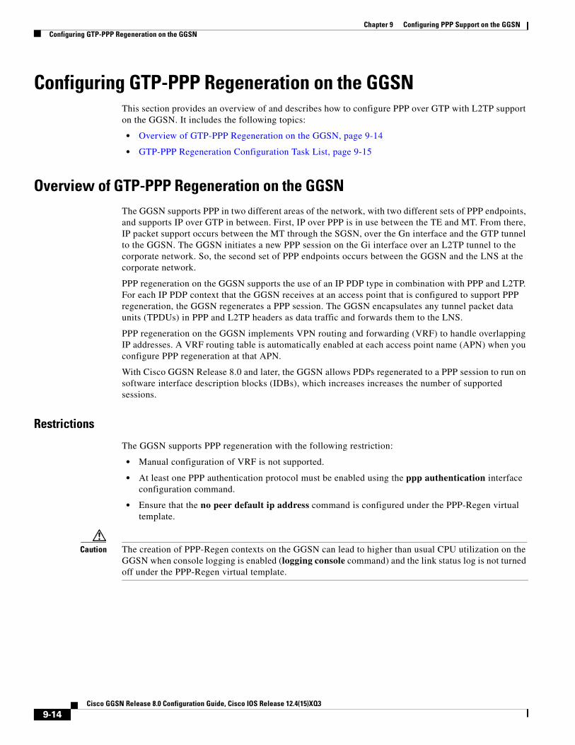
Chapter 9 Configuring PPP Support on the GGSNConfiguring GTP-PPP Regeneration on the GGSN
Configuring GTP-PPP Regeneration on the GGSNThis section provides an overview of and describes how to configure PPP over GTP with L2TP support on the GGSN. It includes the following topics:
• Overview of GTP-PPP Regeneration on the GGSN, page 9-14
• GTP-PPP Regeneration Configuration Task List, page 9-15
Overview of GTP-PPP Regeneration on the GGSNThe GGSN supports PPP in two different areas of the network, with two different sets of PPP endpoints, and supports IP over GTP in between. First, IP over PPP is in use between the TE and MT. From there, IP packet support occurs between the MT through the SGSN, over the Gn interface and the GTP tunnel to the GGSN. The GGSN initiates a new PPP session on the Gi interface over an L2TP tunnel to the corporate network. So, the second set of PPP endpoints occurs between the GGSN and the LNS at the corporate network.
PPP regeneration on the GGSN supports the use of an IP PDP type in combination with PPP and L2TP. For each IP PDP context that the GGSN receives at an access point that is configured to support PPP regeneration, the GGSN regenerates a PPP session. The GGSN encapsulates any tunnel packet data units (TPDUs) in PPP and L2TP headers as data traffic and forwards them to the LNS.
PPP regeneration on the GGSN implements VPN routing and forwarding (VRF) to handle overlapping IP addresses. A VRF routing table is automatically enabled at each access point name (APN) when you configure PPP regeneration at that APN.
With Cisco GGSN Release 8.0 and later, the GGSN allows PDPs regenerated to a PPP session to run on software interface description blocks (IDBs), which increases increases the number of supported sessions.
Restrictions
The GGSN supports PPP regeneration with the following restriction:
• Manual configuration of VRF is not supported.
• At least one PPP authentication protocol must be enabled using the ppp authentication interface configuration command.
• Ensure that the no peer default ip address command is configured under the PPP-Regen virtual template.
Caution The creation of PPP-Regen contexts on the GGSN can lead to higher than usual CPU utilization on the GGSN when console logging is enabled (logging console command) and the link status log is not turned off under the PPP-Regen virtual template.
9-14Cisco GGSN Release 8.0 Configuration Guide, Cisco IOS Release 12.4(15)XQ3
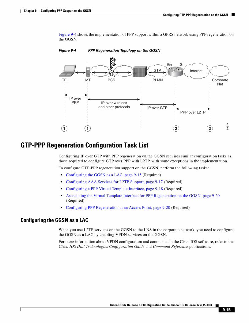
Chapter 9 Configuring PPP Support on the GGSNConfiguring GTP-PPP Regeneration on the GGSN
Figure 9-4 shows the implementation of PPP support within a GPRS network using PPP regeneration on the GGSN.
Figure 9-4 PPP Regeneration Topology on the GGSN
GTP-PPP Regeneration Configuration Task ListConfiguring IP over GTP with PPP regeneration on the GGSN requires similar configuration tasks as those required to configure GTP over PPP with L2TP, with some exceptions in the implementation.
To configure GTP-PPP regeneration support on the GGSN, perform the following tasks:
• Configuring the GGSN as a LAC, page 9-15 (Required)
• Configuring AAA Services for L2TP Support, page 9-17 (Required)
• Configuring a PPP Virtual Template Interface, page 9-18 (Required)
• Associating the Virtual Template Interface for PPP Regeneration on the GGSN, page 9-20 (Required)
• Configuring PPP Regeneration at an Access Point, page 9-20 (Required)
Configuring the GGSN as a LAC
When you use L2TP services on the GGSN to the LNS in the corporate network, you need to configure the GGSN as a LAC by enabling VPDN services on the GGSN.
For more information about VPDN configuration and commands in the Cisco IOS software, refer to the Cisco IOS Dial Technologies Configuration Guide and Command Reference publications.
Internet
CorporateNet
PLMN
IP overPPP
Gn Gi
BSSMTTE
GTP
IP over wirelessand other protocols IP over GTP
PPP over L2TP
5961
9
2211
9-15Cisco GGSN Release 8.0 Configuration Guide, Cisco IOS Release 12.4(15)XQ3

Chapter 9 Configuring PPP Support on the GGSNConfiguring GTP-PPP Regeneration on the GGSN
To configure the GGSN as a LAC where the tunnel parameters are configured locally on the GGSN, use the following commands, beginning in global configuration mode:
Note You can configure the L2TP tunnel parameters locally on the GGSN, or the tunnel parameters can be provided by a RADIUS server. If a RADIUS server is providing the tunnel parameters, then in this procedure you only need to configure the vpdn enable command on the GGSN.
Command Purpose
Step 1 Router(config)# vpdn enable Enables VPDN on the router or instance of Cisco IOS software and directs the router or instance to look for tunnel definitions in a local database and on a remote authorization server (home gateway), if one is present.
Note Only this step is required if you are using a RADIUS server to provide tunnel parameters.
Step 2 Router(config)# vpdn domain-delimiter characters [suffix | prefix]
(Optional) Specifies the characters to be used to delimit the domain prefix or domain suffix. Available characters are %, -, @, \ , #, and /. The default is @.
Note If a backslash (\) is the last delimiter in the command line, enter it as a double backslash (\\).
Step 3 Router(config)# vpdn-group group-number Defines a VPDN group, and enters VPDN group configuration mode.
Step 4 Router(config-vpdn)# request-dialin Enables the router or instance of Cisco IOS software to request dial-in tunnels, and enters request dial-in VPDN subgroup configuration mode.
Step 5 Router(config-vpdn-req-in)# protocol l2tp Specifies use of the L2TP protocol for dial-in tunnels.
Step 6 Router(config-vpdn-req-in)# domain domain-name Specifies that users with this domain name will be tunneled. Configure this command for every domain name you want to tunnel.
Step 7 Router(config-vpdn-req-in)# exit Returns you to VPDN group configuration mode.
Step 8 Router(config-vpdn)# initiate-to ip ip-address [limit limit-number] [priority priority-number]
Specifies the destination IP address for the tunnel.
Step 9 Router(config-vpdn)# local name name Specifies the local name that is used to authenticate the tunnel.
9-16Cisco GGSN Release 8.0 Configuration Guide, Cisco IOS Release 12.4(15)XQ3

Chapter 9 Configuring PPP Support on the GGSNConfiguring GTP-PPP Regeneration on the GGSN
Configuring AAA Services for L2TP Support
Before the VPDN stack on the GGSN opens an L2TP tunnel to an LNS, it tries to authorize the tunnel first. The GGSN consults its local database to perform this authorization. Therefore, you need to configure the appropriate AAA services for the GGSN to support L2TP tunnel authorization. Note that this is for authorization of the tunnel itself—not for user authorization.
This section describes only those commands required to implement authorization for L2TP support on the GGSN. It does not describe all of the tasks required to configure RADIUS and AAA support on the GGSN. For more information about enabling AAA services and configuring AAA server groups on the GGSN, see the “Configuring Security on the GGSN” chapter in this book.
Note To correctly implement authentication and authorization services on the GGSN for L2TP support, you must configure the same methods and server groups for both.
To configure authorization for L2TP support on the GGSN, use the following commands, beginning in global configuration mode:
Command Purpose
Step 1 Router(config)# aaa authorization network default local
(Optional) Specifies that the GGSN consults its local database, as defined by the username command, for tunnel authorization.
9-17Cisco GGSN Release 8.0 Configuration Guide, Cisco IOS Release 12.4(15)XQ3
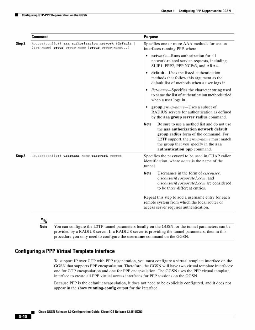
Chapter 9 Configuring PPP Support on the GGSNConfiguring GTP-PPP Regeneration on the GGSN
Note You can configure the L2TP tunnel parameters locally on the GGSN, or the tunnel parameters can be provided by a RADIUS server. If a RADIUS server is providing the tunnel parameters, then in this procedure you only need to configure the username command on the GGSN.
Configuring a PPP Virtual Template Interface
To support IP over GTP with PPP regeneration, you must configure a virtual template interface on the GGSN that supports PPP encapsulation. Therefore, the GGSN will have two virtual template interfaces: one for GTP encapsulation and one for PPP encapsulation. The GGSN uses the PPP virtual template interface to create all PPP virtual access interfaces for PPP sessions on the GGSN.
Because PPP is the default encapsulation, it does not need to be explicitly configured, and it does not appear in the show running-config output for the interface.
Step 2 Router(config)# aaa authorization network {default | list-name} group group-name [group group-name...]
Specifies one or more AAA methods for use on interfaces running PPP, where:
• network—Runs authorization for all network-related service requests, including SLIP1, PPP2, PPP NCPs3, and ARA4.
• default—Uses the listed authentication methods that follow this argument as the default list of methods when a user logs in.
• list-name—Specifies the character string used to name the list of authentication methods tried when a user logs in.
• group group-name—Uses a subset of RADIUS servers for authentication as defined by the aaa group server radius command.
Note Be sure to use a method list and do not use the aaa authorization network default group radius form of the command. For L2TP support, the group-name must match the group that you specify in the aaa authentication ppp command.
Step 3 Router(config)# username name password secret Specifies the password to be used in CHAP caller identification, where name is the name of the tunnel.
Note Usernames in the form of ciscouser, [email protected], and [email protected] are considered to be three different entries.
Repeat this step to add a username entry for each remote system from which the local router or access server requires authentication.
Command Purpose
9-18Cisco GGSN Release 8.0 Configuration Guide, Cisco IOS Release 12.4(15)XQ3

Chapter 9 Configuring PPP Support on the GGSNConfiguring GTP-PPP Regeneration on the GGSN
Be aware that the configuration commands for the PPP virtual template interface to support PPP regeneration on the GGSN are different from the previous configurations shown for GTP over PPP support.
To configure a PPP virtual template interface on the GGSN, use the following commands, beginning in global configuration mode:
Command Purpose
Step 1 Router(config)# interface virtual-template number Creates a virtual template interface, where number identifies the virtual template interface. This command enters you into interface configuration mode.
Note This number must match the number configured in the corresponding gprs gtp ppp-regeneration vtemplate command.
Step 2 Router(config-if)# ip address negotiated Specifies that the IP address for a particular interface is obtained via PPP/IPCP (IP Control Protocol) address negotiation.
Step 3 Router(config-if)# no peer neighbor-route Disables creation of neighbor routes.
Step 4 Router(config-if)#no peer default ip address Disables an IP address from being returned to a remote peer connecting to this interface.
Step 5 Router(config-if)# encapsulation ppp (Optional) Specifies PPP as the encapsulation type for packets transmitted over the virtual template interface. PPP is the default encapsulation.
Note PPP is the default encapsulation and does not appear in the output of the show running-config command for the virtual template interface unless you manually configure the command.
Step 6 Router(config-if)# ppp authentication {protocol1 [protocol2...]} [if-needed] [list-name | default] [callin] [one-time] [optional]
Enables at least one PPP authentication protocol and specifies the order in which the protocols are selected on the interface.
9-19Cisco GGSN Release 8.0 Configuration Guide, Cisco IOS Release 12.4(15)XQ3

Chapter 9 Configuring PPP Support on the GGSNConfiguring GTP-PPP Regeneration on the GGSN
Associating the Virtual Template Interface for PPP Regeneration on the GGSN
Before you associate the virtual template interface for PPP regeneration, you must configure a virtual template interface. The number that you configure for the virtual template interface must correspond to the number that you specify in the gprs gtp ppp-regeneration vtemplate command.
To associate the virtual template interface for PPP regeneration, use the following command in global configuration mode:
Configuring PPP Regeneration at an Access Point
To enable PPP regeneration on the GGSN, you must configure each access point for which you want to support PPP regeneration. There is no global configuration command for enabling PPP regeneration for all access points on the GGSN.
To create an access point and specify its type, use the following commands, beginning in global configuration mode:
Command PurposeRouter(config)# gprs gtp ppp-regeneration vtemplate number Associates the virtual template interface that
defines the PPP characteristics with support for the PPP regeneration on the GGSN.
Note This number must match the number configured in the corresponding interface virtual-template command.
Command Purpose
Step 1 Router(config)# gprs access-point-list list-name Specifies a name for a new access point list, or references the name of the existing access point list, and enters access-point list configuration mode.
Step 2 Router(config-ap-list)# access-point access-point-index
Specifies an index number for a new access point definition, or references an existing access point definition, and enters access point configuration mode.
Step 3 Router(config-access-point)# access-point-name apn-name
Specifies the access point network ID, which is commonly an Internet domain name.
Note The apn-name must match the APN that has been provisioned at the MS, home location register (HLR), and Domain Name System (DNS) server.
9-20Cisco GGSN Release 8.0 Configuration Guide, Cisco IOS Release 12.4(15)XQ3

Chapter 9 Configuring PPP Support on the GGSNMonitoring and Maintaining PPP on the GGSN
Monitoring and Maintaining PPP on the GGSNThis section provides a summary list of the show commands that you can use to monitor the different aspects of PPP configuration on the GGSN. Not all of the show commands apply to every method of configuration.
Step 4 Router(config-access-point)# access-mode transparent
(Optional) Specifies that no security authorization or authentication is requested by the GGSN for this access point.
Note Transparent access is the default value, but it must be manually configured to support PPP regeneration at the access point if the access mode was previously non-transparent.
Step 5 Router(config-access-point)# ppp-regeneration [max-session number | setup-time seconds | verify-domain | fixed-domain]
Enables an access point to support PPP regeneration, where:
• max-session number—Specifies the maximum number of PPP regenerated sessions allowed at the access point. The default value is 65535.
• setup-time seconds—Specifies the maximum amount of time (between 1 and 65535 seconds) within which a PPP regenerated session must be established. The default value is 60 seconds.
• verify-domain—Configures the GGSN to verify the domain sent in the protocol configuration option (PCO) IE sent in a Create PDP Context request against the APN sent out by the user when PPP-regeneration is being used.
If a mismatch occurs, the Create PDP Context request is rejected with the cause code “Service not supported.”
• fixed-domain—Configures the GGSN to use the access point name as the domain name with which it initiates an L2TP tunnel to the user when PPP-regeneration is being used.
The ppp-regeneration fixed-domain and ppp-regeneration verify-domain command configurations are mutually exclusive. When the ppp-regeneration fixed-domain command is configured, domain verification cannot be performed.
Command Purpose
9-21Cisco GGSN Release 8.0 Configuration Guide, Cisco IOS Release 12.4(15)XQ3

Chapter 9 Configuring PPP Support on the GGSNConfiguration Examples
Use the following privileged EXEC commands to monitor and maintain PPP status on the GGSN:
Configuration ExamplesThis section provides configuration examples for the different types of PPP support on the GGSN. It includes the following examples:
• GTP-PPP Termination on the GGSN Configuration Examples, page 9-22
• GTP-PPP–Over–L2TP Configuration Example, page 9-24
• GTP-PPP Regeneration Configuration Example, page 9-25
• AAA Services for L2TP Configuration Example, page 9-26
GTP-PPP Termination on the GGSN Configuration ExamplesThe following example shows a GGSN configuration for GTP over PPP using PAP authentication using a RADIUS server at 172.16.0.2 to allocate IP addresses:
Router# show running-configBuilding configuration...Current configuration : 3521 bytes!version 12.2no service single-slot-reload-enableno service padservice timestamps debug uptimeservice timestamps log uptimeno service password-encryption!! Enables the router for GGSN services!
Command PurposeRouter# show derived-config interface virtual-access number
Displays the PPP options that GTP has configured on the virtual access interface for PPP regenerated sessions.
Router# show gprs gtp pdp-context all Displays all currently active PDP contexts.
Router# show gprs gtp pdp-context path ip-address Displays all currently active PDP contexts for the specified SGSN path.
Router# show gprs gtp pdp-context pdp-type ppp Displays all currently active PDP contexts that are transmitted using PPP.
Router# show gprs gtp status Displays information about the current status of the GTP on the GGSN.
Router# show interfaces virtual-access number [configuration]
Displays status, traffic data, and configuration information about a specified virtual access interface.
Router# show vpdn session [all | packets | sequence | state | timers | window] [interface | tunnel | username]
Displays VPN session information including interface, tunnel, username, packets, status, and window statistics.
Router# show vpdn tunnel [all | packets | state | summary | transport] [id | local-name | remote-name]
Displays VPN tunnel information including tunnel protocol, ID, local and remote tunnel names, packets sent and received, tunnel, and transport status.
9-22Cisco GGSN Release 8.0 Configuration Guide, Cisco IOS Release 12.4(15)XQ3

Chapter 9 Configuring PPP Support on the GGSNConfiguration Examples
service gprs ggsn!ip cef!no logging bufferedlogging rate-limit console 10 except errors!! Enables AAA globally!aaa new-model!! Defines AAA server group ! aaa group server radius gtp_ppp server 172.16.0.2 auth-port 2001 acct-port 2002!! Configures authentication and authorization! methods for PPP support.!aaa authentication ppp gtp_ppp group gtp_pppaaa authorization network gtp_ppp group gtp_pppaaa accounting network default start-stop group gtp_ppp!ip subnet-zero!! Configures a loopback interface! for the PPP virtual template interface! interface Loopback2 ip address 10.88.0.4 255.255.0.0!...!! Configures a VT interface for! GTP encapsulation!interface loopback 1 ip address 10.30.30.1 255.255.255.0!interface Virtual-Template1 ip unnumber loopback 1 encapsulation gtp gprs access-point-list gprs!! Configures a VT interface for! PPP encapsulation!interface Virtual-Template2 ip unnumbered Loopback2 no peer default ip address ppp authentication pap!...!gprs access-point-list gprs access-point 1 access-point-name gprs.cisco.com aaa-group authentication gtp_ppp aaa-group accounting gtp_ppp exit !! Associates the PPP virtual template! interface for use by the GGSN!
9-23Cisco GGSN Release 8.0 Configuration Guide, Cisco IOS Release 12.4(15)XQ3

Chapter 9 Configuring PPP Support on the GGSNConfiguration Examples
gprs gtp ppp-vtemplate 2gprs default charging-gateway 10.7.0.2!gprs memory threshold 512!! Configures a global RADIUS server host! and specifies destination ports for ! authentication and accounting requests!radius-server host 172.16.0.2 auth-port 2001 acct-port 2002radius-server retransmit 3radius-server key cisco!!end
GTP-PPP–Over–L2TP Configuration ExampleThe following example shows a partial configuration of the GGSN to support PPP over GTP with L2TP. Tunnel parameters are configured locally on the GGSN and are not provided by a RADIUS server.
. . .!! Enables AAA globally!aaa new-model!aaa authorization network default local!vpdn enable!! Configures a VPDN group!vpdn-group 1 request-dialin protocol l2tp domain ppp-lns initiate-to ip 4.0.0.78 priority 1 local name nas!! Configures a loopback interface! for the PPP virtual template interface!interface Loopback2 ip address 10.88.0.1 255.255.255.255!interface Virtual-Template2 description VT for PPP L2TP ip unnumbered Loopback2 no peer default ip address no peer neighbor-route ppp authentication pap chap!
9-24Cisco GGSN Release 8.0 Configuration Guide, Cisco IOS Release 12.4(15)XQ3

Chapter 9 Configuring PPP Support on the GGSNConfiguration Examples
gprs access-point-list gprs access-point 15 access-point-name ppp-lns exit!! Associates the PPP virtual template! interface for use by the GGSN!gprs gtp ppp vtemplate 2!. . .!
GTP-PPP Regeneration Configuration ExampleThe following example shows a partial configuration of the GGSN to support IP over GTP with PPP regeneration on the GGSN. Tunnel parameters are configured locally on the GGSN and are not provided by a RADIUS server.
!. . . !! Enables AAA globally!vpdn enable!! Configures a VPDN group!vpdn-group 1 request-dialin protocol l2tp domain ppp_regen1 initiate-to ip 4.0.0.78 priority 1 l2tp tunnel password 7 0114161648!! Configures a virtual template! interface for PPP regeneration! interface Virtual-Template2 description VT for PPP Regen ip address negotiated no peer neighbor-route no peer default ip address ppp authentication pap chap!gprs access-point-list gprs access-point 6 access-point-name ppp_regen1 ppp-regeneration exit!! Associates the PPP-regeneration! virtual template interface for use by the GGSN!gprs gtp ppp-regeneration vtemplate 2
9-25Cisco GGSN Release 8.0 Configuration Guide, Cisco IOS Release 12.4(15)XQ3

Chapter 9 Configuring PPP Support on the GGSNConfiguration Examples
AAA Services for L2TP Configuration ExampleL2TP support is used on the GGSN to support both the PPP-over-GTP topology and the IP–over–GTP with PPP regeneration topology. The following examples shows a partial configuration of RADIUS and AAA services on the GGSN to provide L2TP support:
!! Enables AAA globally!aaa new-model!! Defines AAA server group ! aaa group server radius gtp_ppp server 172.16.0.2 auth-port 2001 acct-port 2002!! Configures authentication and authorization! method gtp_ppp and AAA server group gtp_ppp ! for PPP support.!! NOTE: You must configure the same methods and groups ! to support L2TP as shown by the ! aaa authentication ppp gtp_ppp! and aaa authorization network gtp_ppp commands.!aaa authentication ppp gtp_ppp group gtp_pppaaa authorization network default localaaa authorization network gtp_ppp group gtp_pppaaa accounting network default start-stop group radiususername nas password 0 labusername hgw password 0 lab!. . .!! Configures a global RADIUS server host! and specifies destination ports for ! authentication and accounting requests!radius-server host 172.16.0.2 auth-port 2001 acct-port 2002radius-server retransmit 3radius-server key cisco!. . .!
9-26Cisco GGSN Release 8.0 Configuration Guide, Cisco IOS Release 12.4(15)XQ3
Cisco GGSN Release 8.0
C H A P T E R10
Configuring QoS on the GGSNThis chapter describes how to configure quality of service (QoS) functions to differentiate traffic flow through the gateway GPRS support node (GGSN) on the Cisco SAMI in the Cisco 7600 series router platform.
For a complete description of the GGSN commands in this chapter, refer to the Cisco GGSN Command Reference for the Cisco GGSN release you are using. To locate documentation of other commands that appear in this chapter, use the command reference master index or search online.
This chapter includes the following sections:
• Overview of QoS Support on the GGSN, page 10-1
• Configuring UMTS QoS on the GGSN, page 10-2
• Configuring the GGSN Default QoS as Requested QoS, page 10-12
• Configuring Call Admission Control on the GGSN, page 10-12
• Configuring Per-PDP Policing, page 10-16
• Monitoring and Maintaining QoS on the GGSN, page 10-19
• Configuration Examples, page 10-21
Overview of QoS Support on the GGSNThe Cisco GGSN software supports 3G Universal Mobile Telecommunication System (UMTS) QoS. Each GPRS/UMTS packet data protocol (PDP) context request contains a UMTS QoS profile.
The implementation of QoS support in the GPRS/UMTS public LAN mobile network (PLMN) varies by the service provider and the available resources in the network. The 3GPP standards define the UMTS QoS classes that can be defined by a UMTS MS. However, the resulting QoS is negotiated and variable within the GPRS/UMTS network backbone according to the implementations of the service provider.
UMTS QoS
To manage different level of QoS, UMTS has defined the four QoS traffic classes based on delay, jitter, bandwidth, and reliability factors:
• Conversational
• Streaming
• Interactive
• Background
10-1Configuration Guide, Cisco IOS Release 12.4(15)XQ3

Chapter 10 Configuring QoS on the GGSNConfiguring UMTS QoS on the GGSN
The Cisco GGSN delivers end-to-end UMTS QoS by implementing it using the Cisco IOS QoS differentiated services (Diffserv).
This chapter describes the QoS support that the GGSN provides for the UMTS QoS classes.
Configuring UMTS QoS on the GGSNThis section describes how to configure the UMTS QoS on the GGSN. It includes the following topics:
• Overview of UMTS QoS, page 10-2
• Configuring UMTS QoS Task Lists, page 10-3
• Enabling UMTS QoS Mapping on the GGSN, page 10-3
• Mapping UMTS QoS Traffic Classes to a DiffServ PHB Group, page 10-3
• Assigning a DSCP to a DiffServ PHB Group, page 10-4
• Configuring the DSCP in the Subscriber Datagram, page 10-6
• Configuring the Cisco 7600 Platform GGSN UMTS QoS Requirements, page 10-7
• Verifying the UMTS QoS Configuration, page 10-10
Overview of UMTS QoS3GPP standards define four QoS traffic classes based on delay, jitter, bandwidth, and reliability for UMTS. Table 10-1 describes these UMTS traffic classes and their characteristics, applications, and the mapped Cisco IOS QoS Diffserv class.
Table 10-1 UMTS Traffic Classes
Traffic ClassConversational(Real Time)
Streaming(Real Time)
Interactive(Best Effort)
Background(Best Effort)
Characteristics Preserve time relation (variation) between information entities of the stream.
Conversational pattern, therefore, very low delay and jitter.
Preserve time relation (variation) between information entities of the stream.
Delay and jitter requirements are not as strict as with the conversational class.
Request/response pattern.
Retransmission of payload content in-route.
Destination is not expecting the data with a stringent time.
Retransmission of payload content in-route might occur.
Example Applications
Voice over IP Streaming audio and video
Web browsing Downloading email
Diffserv Class / Map to DSCP
Expedited Forwarding Class
Assured Forwarding 2 Class
Assured Forwarding 3 Class
Best Effort
10-2Cisco GGSN Release 8.0 Configuration Guide, Cisco IOS Release 12.4(15)XQ3

Chapter 10 Configuring QoS on the GGSNConfiguring UMTS QoS on the GGSN
The Cisco GGSN supports end-to-end UMTS QoS by implementing it using the Cisco IOS Differentiated Services (DiffServ) model. The DiffServ model is a multiple-service model that can satisfy differing QoS requirements. With DiffServ, the network tries to deliver a particular kind of service based on the QoS specified by each packet. This specification can occur in different ways, for example, using the 6-bit differentiated services code point (DSCP) setting in IP packets or source and destination addresses. The network uses the QoS specification to classify, mark, shape, and police traffic, and to perform intelligent queueing.
For complete information on Cisco IOS QoS and the DiffServ service model, refer to the Cisco IOS Quality of Service Solutions Configuration Guide.
Configuring UMTS QoS Task ListsTo implement the UMTS QoS method on a GGSN, you must first enable the function. From there, you can modify the UMTS QoS options to support your network needs.
Configuring GGSN UMTS QoS on the Cisco 7600 Platform Task List
If configuring UMTS QoS on a GGSN on the Cisco 7600 platform, perform the following tasks:
• Enabling UMTS QoS Mapping on the GGSN, page 10-3 (Required)
• Mapping UMTS QoS Traffic Classes to a DiffServ PHB Group, page 10-3 (Optional)
• Assigning a DSCP to a DiffServ PHB Group, page 10-4 (Optional)
• Configuring the DSCP in the Subscriber Datagram, page 10-6 (Optional)
• Configuring the Cisco 7600 Platform GGSN UMTS QoS Requirements, page 10-7 (Required)
• Configuring Call Admission Control on the GGSN, page 10-12 (Optional)
• Verifying the UMTS QoS Configuration, page 10-10
Enabling UMTS QoS Mapping on the GGSNBy default, UMTS QoS is not enabled on the GGSN. To enable UMTS QoS on the GGSN, use the following command in global configuration mode:
Mapping UMTS QoS Traffic Classes to a DiffServ PHB GroupBefore you can specify a QoS mapping from the UMTS QoS traffic classes to a DiffServ per-hop behavior (PHB) group, you must enable UMTS QoS mapping using the gprs qos map umts global configuration command.
The default mapping values for UMTS QoS traffic classes are as follows:
• Conversational traffic class to the ef-class DiffServ PHB group
• Streaming traffic class to the af2-class DiffServ PHB group
Command Purpose
Router(config)# gprs qos map umts Enables UMTS QoS mapping on the GGSN.
10-3Cisco GGSN Release 8.0 Configuration Guide, Cisco IOS Release 12.4(15)XQ3

Chapter 10 Configuring QoS on the GGSNConfiguring UMTS QoS on the GGSN
• Interactive traffic class to the af3-class DiffServ PHB group
• Background traffic class to the best-effort DiffServ PHB group
If you wish to use mapping values other than these defaults, you can use the gprs umts-qos map traffic-class command to map a UMTS traffic class to another DiffServ PHB group.
Note To successfully map UMTS QoS traffic classes to a DiffServ PHB, the class maps must be configured using the class map and match ip dscp Cisco IOS software commands. For more information about configuring class maps, refer to the Cisco IOS Quality of Service Solutions Configuration Guide.
To map a UMTS traffic class to a DiffServ PHB group, use the following command in global configuration mode:
Assigning a DSCP to a DiffServ PHB GroupBy default, the default differentiated services code point (DSCP) value associated with a PHB class is used. Table 10-2 lists the default DSCP values for each PHB group.
Command Purpose
Router(config)# gprs umts-qos map traffic-class traffic-class diffserv-phb-group
Enables mapping of UMTS QoS traffic classes to a DiffServ PHB, where the UMTS traffic classes are:
• signalling
• conversational
• streaming
• interactive
• background
and the DiffServ PHB groups are:
• signalling-class
• ef-class
• af1-class
• af2-class
• af3-class
• af4-class
• best-effort
Table 10-2 Default DSCP Values for PHB Groups
PHB Group DSCP Value
EF 101110
AF11 001010
AF12 001100
AF13 001110
10-4Cisco GGSN Release 8.0 Configuration Guide, Cisco IOS Release 12.4(15)XQ3
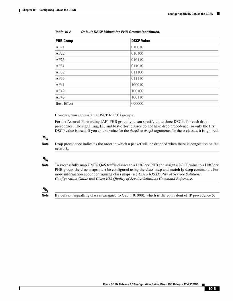
Chapter 10 Configuring QoS on the GGSNConfiguring UMTS QoS on the GGSN
However, you can assign a DSCP to PHB groups.
For the Assured Forwarding (AF) PHB group, you can specify up to three DSCPs for each drop precedence. The signalling, EF, and best-effort classes do not have drop precedence, so only the first DSCP value is used. If you enter a value for the dscp2 or dscp3 arguments for these classes, it is ignored.
Note Drop precedence indicates the order in which a packet will be dropped when there is congestion on the network.
Note To successfully map UMTS QoS traffic classes to a DiffServ PHB and assign a DSCP value to a DiffServ PHB group, the class maps must be configured using the class map and match ip dscp commands. For more information about configuring class maps, see Cisco IOS Quality of Service Solutions Configuration Guide and Cisco IOS Quality of Service Solutions Command Reference.
Note By default, signalling class is assigned to CS5 (101000), which is the equivalent of IP precedence 5.
AF21 010010
AF22 010100
AF23 010110
AF31 011010
AF32 011100
AF33 011110
AF41 100010
AF42 100100
AF43 100110
Best Effort 000000
Table 10-2 Default DSCP Values for PHB Groups (continued)
PHB Group DSCP Value
10-5Cisco GGSN Release 8.0 Configuration Guide, Cisco IOS Release 12.4(15)XQ3

Chapter 10 Configuring QoS on the GGSNConfiguring UMTS QoS on the GGSN
To assign a DSCP value to a DiffServ PHB group, use the following command in global configuration mode:
Configuring the DSCP in the Subscriber DatagramBy default, the DSCP in subscriber datagrams is re-marked with the DSCP assigned to the traffic class when the PDP context was created.
To specify that the subscriber datagram be forwarded through the GTP path without modifying its DSCP, use the following command in global configuration mode:
To return to the default value, issue the no gprs umts-qos dscp unmodified command.
Command PurposeRouter(config)# gprs umts-qos map diffserv-phb diffserv-phb-group [dscp1] [dscp2] [dscp3]
Assigns a DSCP to a DiffServ PHB group where the DiffServ PHB groups are:
• signalling
• ef-class
• af1-class
• af2-class
• af3-class
• af4-class
• best-effort
and the DSCPs are:
• dscp1—Required for all classes. Specifies one of 64 DSCP values from 0 to 63. This DSCP value corresponds to drop precedence 1.
• dscp2—(Optional for AF classes) Specifies one of 64 DSCP values from 0 to 63. This DSCP value corresponds to drop precedence 2.
• dscp3—(Optional for AF classes) Specifies one of 64 DSCP values from 0 to 63. This DSCP value corresponds to drop precedence 3.
Command PurposeRouter(config)# gprs umts-qos dscp unmodified [up | down | all]
Specifies that the subscriber datagram be forwarded through the GTP path without modifying its DSCP.
10-6Cisco GGSN Release 8.0 Configuration Guide, Cisco IOS Release 12.4(15)XQ3

Chapter 10 Configuring QoS on the GGSNConfiguring UMTS QoS on the GGSN
Configuring the Cisco 7600 Platform GGSN UMTS QoS RequirementsWhen configuring UMTS QoS for a GGSN running on a Cisco Service and Application Module for IP (SAMI) in the Cisco 7600 platform, the different components of the platform perform different QoS functions. Table 10-3 summarizes the QoS function performed by the Cisco 7600 platform component.
After you configure UMTS QoS on the GGSN, ensure the following tasks are completed:
Supervisor Engine
Note The following list is a summary of the required tasks that need to be completed on the supervisor engine for UMTS QoS on a GGSN. For complete information each of these tasks, see the Cisco 7600 Series Cisco IOS Software Configuration Guide.
1. Enable Mutlilayer Switching QoS using the mls qos global configuration command.
Router# mls qos
2. On the supervisor engine, configure aggregate policing for Gi traffic.
Note Because there can be multiple Gn and Gi interfaces, but all the traffic eventually needs to go to a single GE port on the SAMI (one GE port for two GGSNs), we recommend that you use a Named Aggregate Policer to rate limit the traffic to the SAMI. We also recommend dropping all non-conforming traffic.
The following example illustrates the configuration for a named aggregate policer. The named policer is attached to the Gi interface:
Access-list 101 permit ip any any dscp efAccess-list 102 permit ip any any dscp af21Access-list 103 permit ip any any dscp af31Access-list 103 permit ip any any dscp af32Access-list 103 permit ip any any dscp af33Access-list 104 permit ip any any
Class-map match-all conversational Match access-group 101Class-map match-all streaming Match access-group 102Class-map match-all interactive Match access-group 103Class-map match-all background Match access-group 104
Table 10-3 QoS Function by Cisco 7600 Platform Component
Cisco 7600 Component UMTS QoS Function
Catalyst Line Card Classification and ingress and egress scheduling
Supervisor Engine Classification and aggregate policing
Cisco IOS GGSN image on the Cisco SAMI Classification, DSCP marking, and output queuing
10-7Cisco GGSN Release 8.0 Configuration Guide, Cisco IOS Release 12.4(15)XQ3

Chapter 10 Configuring QoS on the GGSNConfiguring UMTS QoS on the GGSN
Mls qos aggregate-policer AGGREGATE-CONV bit-rate1 normal-burst max-burst conform-action transmit exceed-action dropMls qos aggregate-policer AGGREGATE-STREAMING bit-rate1 normal-burst max-burst conform-action transmit exceed-action dropMls qos aggregate-policer AGGREGATE-INTERACTIVE bit-rate1 normal-burst max-burst conform-action transmit exceed-action dropMls qos aggregate-policer AGGREGATE-BACKGROUND bit-rate1 normal-burst max-burst conform-action transmit exceed-action drop
Policy-map Gi-incoming Class conversational Police aggregate AGGREGATE-CONV Class streaming Police aggregate AGGREGATE-STREAMING Class interactive Police aggregate AGGREGATE-INTERACTIVE Class background Police aggregate AGGREGATE-BACKGROUND
Router(config-if)# service-policy input Gi-incoming
Note To monitor policing statistics, you can use the following show commands: - show mls qos aggregate-policer name - show policy-map interface interface - show policy interface interface
3. Set the trust state of the ingress ports to trust-dscp mode using the msl qos trust dscp interface configuration command:
Router(config)# interface FastEthernet2/1Router(config-if)# mls qos trust dscp
4. Configure egress port scheduling by completing the following tasks:
a. Obtain the UMTS traffic class-to-DSCP mappings using the show gprs umts-qos traffic class privilege EXEC command on the GGSN instance running on the Cisco SAMI:
Router# ggsn show gprs umts-qos traffic-class
b. Obtain the default DSCP-to-CoS mapping by displaying the QoS mapping information using the show mls qos maps privilege EXEC command.
Router# show mls qos maps
c. Obtain the default CoS-to-queue mapping by displaying the queueing statistics of an interface using the show queuing interface privilege EXEC command.
Router# show queuing interface interface
10-8Cisco GGSN Release 8.0 Configuration Guide, Cisco IOS Release 12.4(15)XQ3

Chapter 10 Configuring QoS on the GGSNConfiguring UMTS QoS on the GGSN
d. Using the information obtained in Steps A, B, and C, determine if customized egress DSCP-to-CoS mapping is necessary and if so, define the mapping using the mls qos map dscp-cos global configuration command.
Router(config)# mls qos map dscp-cos dscp to cos
When customizing DSCP-CoS mapping, ensure that:
- Conversational and streaming traffic are put into egress queue 4
- Interactive and background traffic are equally distributed between the two normal queues.
- Interactive traffic is mapped to different CoS values so that different thresholds can be configured on the queue to take advantage of WRED.
5. If the line card supports Weighted Random Early Detection WRED, configure congestion avoidance by completing the following tasks:
a. Enable WRED and specify the minimum and maximum threshold for specified queues using the wrr-queue random-detect max-threshold interface configuration command (the defaults are recommended).
Router(config-if)# wrr-queue random-detect max-threshold queue percent-of-queue-size
b. Map CoS values to drop thresholds using the wrr-queue cos map interface configuration command. When the threshold is exceeded, frames with specific CoS values will be dropped.
wrr-queue cos-map queue-id threshold-id cos-1 ... cos-n
In the following example, CoS values 3 and 4 are assigned to transmit queue 1/threshold 2 and transmit 2/threshold 1.
Router(config-if)# wrr-queue cos-map 1 1 3Router(config-if)# wrr-queue cos-map 1 2 4
c. Allocate bandwidth between standard transmit queue 1 (low priority) and standard transmit queue 2 (high priority) using the wrr-queue bandwidth interface configuration command.
Router(config-if)# wrr-queue bandwidth weight1 weight2 weight3
Cisco GGSN
1. Configure an output queueing strategy for the UMTS traffic classes for each GGSN.
You can configure a queueing strategy for each of the UMTS traffic classes for each GGSN.
The following configuration example assumes that the UMTS traffic classes and class maps have been defined.
Interface GigabitEthernet0/0Bandwidth <max-bandwidth>
Service-policy output sami-output
Policy-map sami-outputClass conversational
Priority percent 5Class streaming
Priority percent15Class interactive
Bandwidth 20Class background
Bandwidth 20Class signaling
Bandwidth 15
10-9Cisco GGSN Release 8.0 Configuration Guide, Cisco IOS Release 12.4(15)XQ3

Chapter 10 Configuring QoS on the GGSNConfiguring UMTS QoS on the GGSN
Verifying the UMTS QoS ConfigurationTo verify your UMTS QoS configuration, use the show running-config command on the supervisor engine and the GGSN instance running on the Cisco SAMI and observe the UMTS QoS parameters in the following example:
Supervisor Engine Configuration:Mls qos
Mls qos map dscp-cos 18 20 22 to 5Mls qos map dscp-cos 26 to 4Mls qos map dscp-cos 28,30 to 3
Access-list 101 permit ip any any dscp efAccess-list 102 permit ip any any dscp af21Access-list 103 permit ip any any dscp af31Access-list 103 permit ip any any dscp af32Access-list 103 permit ip any any dscp af33Access-list 104 permit ip any any
Class-map match-all conversational Match access-group 101Class-map match-all streaming
Match access-group 102Class-map match-all interactive
Match access-group 103Class-map match-all background
Match access-group 104
Mls qos aggregate-policer AGGREGATE-CONV <bit rate1> <normal-burst> <max-burst>Conform-action transmit exceed-action dropMls qos aggregate-policer AGGREGATE-STREAMING <bit rate2> <normal-burst> <max-burst> conform-action transmit exceed-action dropMls qos aggregate-policer AGGREGATE-INTERACTIVE <bit rate3> <normal-burst> <max-burst> conform-action transmit exceed-action dropMls qos aggregate-policer AGGREGATE-BACKGROUND <bit rate4> <normal-burst> <max-burst> conform-action transmit exceed-action drop
Policy-map Gi-incomingClass conversational
Police aggregate AGGREGATE-CONVClass streaming
Police aggregate AGGREGATE-STREAMINGClass interactive
Police aggregate AGGREGATE-INTERACTIVEClass background
Police aggregate AGGREGATE-BACKGROUND
10-10Cisco GGSN Release 8.0 Configuration Guide, Cisco IOS Release 12.4(15)XQ3

Chapter 10 Configuring QoS on the GGSNConfiguring UMTS QoS on the GGSN
Interface FastEthernet2/1Description “Gi interface”Mls qos trust dscpWrr-queue cos-map 1 1 3
Wrr-queue cos-map 1 2 4 Wrr-queue bandwidth 50 40 10
Service-policy input Gi-incoming
Interface FastEthernet2/2Description “Gn interface”Mls qos trust dscp
GGSN ConfigurationGprs qos map umts
Class-map match-all conversationalMatch ip dscp 46
Class-map match-any interactiveMatch ip dscp 26Match ip dscp 28Match ip dscp 30
Class-map match-any streamingMatch ip dscp 18Match ip dscp 20Match ip dscp 22
Class-map match-all signalingMatch ip dscp 40
Class-map match-any backgroundDescription default classMatch ip dscp 0
Policy-map sami-outputClass conversational
Priority percent 5Class streaming
Priority percent 15Class interactive
Bandwidth 20Class background
Bandwidth 20Class signaling
Bandwidth 15
interface Gigabitthernet 0/0 bandwidth 250000 service-policy output max-output
10-11Cisco GGSN Release 8.0 Configuration Guide, Cisco IOS Release 12.4(15)XQ3

Chapter 10 Configuring QoS on the GGSNConfiguring the GGSN Default QoS as Requested QoS
Configuring the GGSN Default QoS as Requested QoSIf you are not using UMTS QoS mapping on the GGSN, you can configure the GGSN to set its default QoS values in the response message exactly as requested in the Create PDP Context request. By using this command, you can prevent the GGSN from lowering the requested QoS.
To configure the GGSN to set the requested QoS as the default QoS, use the following command, beginning in global configuration mode:
Note When the gprs qos default-response requested command is not configured, and GPRS canonical QoS is not enabled, the GGSN sets its default QoS class to best effort.
Configuring Call Admission Control on the GGSNThe Call Admission Control (CAC) feature on the GGSN ensures that required network resources are available for real-time data traffic such as voice and video. CAC is applied at the APN and consists of two functions: maximum QoS authorization and bandwidth management.
The following sections describe how to configure these functions on the GGSN:
• Configuring Maximum QoS Authorization, page 10-12
• Configuring Bandwidth Management, page 10-15
• Configuration Examples, page 10-21
• CAC Configuration Example, page 10-23
Note CAC on the GGSN requires that UMTS QoS has been enabled using the gprs qos map umts global configuration command and that traffic class criterion and traffic policies have been created.
Configuring Maximum QoS AuthorizationThe CAC maximum QoS authorization function ensures that the QoS requested by a create PDP context does not exceed the maximum QoS configured within an APN. Using a CAC maximum QoS policy, you define certain QoS parameters within a policy and attach the policy to an APN. The CAC maximum QoS policy limits the QoS requested by the PDP during its creation and modification process.
Note A CAC maximum QoS policy can be attached to multiple APNs.
Command PurposeRouter(config)# gprs qos default-response requested (Optional) Specifies that the GGSN sets its default QoS
values in the response message exactly as requested in the Create PDP Context request.
10-12Cisco GGSN Release 8.0 Configuration Guide, Cisco IOS Release 12.4(15)XQ3

Chapter 10 Configuring QoS on the GGSNConfiguring Call Admission Control on the GGSN
The following parameters can be defined in a CAC maximum QoS policy:
• Maximum number of active PDP contexts—Maximum number of active PDP contexts for an APN. If the total number of active PDPs on an APN exceeds the number configured with this parameter in a policy, the GGSN rejects the PDP context. Optionally, you can configure CAC to accept only PDP contexts with Allocation/Retention priority set to 1 after the threshold is reached.
• Maximum bit rate—Highest maximum bit rate (MBR) that can be allowed for each traffic class in both the uplink and downlink directions for an APN. If an MBR is configured in the policy, CAC ensures that the MBR is greater than the maximum GBR. If an MBR is not configured, CAC accepts any MBR requested by a PDP context.
• Guaranteed bit rate—Highest guaranteed bit rate (GBR) that can be accepted for real-time traffic (conversational and streaming) in both the uplink and downlink directions for an APN. If a GBR is not configured in the policy, the CAC accepts any GBR requested by a PDP context.
• Highest traffic class—Highest traffic class that can be accepted at an APN. If the requested traffic class is higher than the highest traffic class specified in the policy, the PDP context is rejected. If this parameter is not configured, any traffic class is accepted.
The GGSN does not downgrade the traffic classes during PDP context creation, however, the GGSN does downgrade the traffic class during the PDP context modification if the highest traffic class configured in an APN is changed after the PDP context creation and the GGSN receives a request for a new traffic class (in a PDP context update request) that is greater than the new highest traffic class. If this occurs, the GGSN downgrades the request to the new highest traffic class.
• Maximum traffic handling priority—Specifies the maximum traffic handling priority for interactive traffic class that can be accepted at an APN. If this parameter is not specified, all traffic handling priorities are accepted.
• Maximum delay class—Defines the maximum delay class for R97/R98 QoS that can be accepted at an APN.
• Maximum peak throughput class—Defines the maximum peak throughput class for R97/R98 QoS that can be accepted at an APN.
Configuring a CAC Maximum QoS Policy
To configure a CAC maximum QoS policy, use the following commands, beginning in global configuration mode:
Command Purpose
Step 1 Router(config)# gprs qos cac-policy policy-name Creates or modifies a CAC maximum QoS policy.
Step 2 Router(config-umts-cac-policy)# maximum pdp-context number [threshold number2]
Specifies the maximum number PDP contexts that can be created for a particular APN. Optionally, a second threshold can be configured that after reached, only PDP contexts with allocation/retention priority 1 are accepted.
Step 3 Router(config-umts-cac-policy)# maximum traffic-class traffic-class-name [priority value]
Specifies the highest traffic class that can be accepted at an APN. Valid values are conversational, streaming, interactive, or background.
Optionally, the highest traffic handling priority for the interactive traffic class can be specified.
10-13Cisco GGSN Release 8.0 Configuration Guide, Cisco IOS Release 12.4(15)XQ3

Chapter 10 Configuring QoS on the GGSNConfiguring Call Admission Control on the GGSN
Step 4 Router(config-umts-cac-policy)# maximum peak-throughput value [reject]
Defines the maximum peak throughput for R97/R98 QoS that can be accepted at an APN. Valid values are between 1 and 9.
By default, PDP contexts for which the peak throughput is higher than the configured value are downgraded to the configured value. Optionally, you can specify the reject keyword to have these PDP contexts rejected instead.
Step 5 Router(config-umts-cac-policy)# maximum delay-class value [reject]
Specifies the maximum delay class for R97/R98 QoS that can be accepted at an APN.
By default, PDP contexts for which the maximum delay-class is higher than the configured value are downgraded to the configured value. Optionally, you can specify the reject keyword to have these PDP contexts rejected instead.
Step 6 Router(config-umts-cac-policy)# mbr traffic-class traffic-class-name bitrate {uplink | downlink} [reject]
Specifies the maximum bit rate (MBR) that can be allowed for each traffic class in both directions (downlink and uplink). Valid value is between 1 and 16000.
Note Although the valid command range for both the uplink and downlink direction is 1 to 16000, the maximum rate that can be acheived in the uplink direction is 8640. Additionally, a value greater than 8640 in the downlink direction is supported for GTPv1 PDPs only.
Optionally, using the reject keyword option, you can specify for create PDP context requests to be rejected when the MBR exceeds the configured value.
Step 7 Router(config-umts-cac-policy)# gbr traffic-class traffic-class-name bitrate {uplink | downlink} [reject]
Specifies the highest guaranteed bit rate (GBR) that can be allowed in uplink and downlink directions for real-time classes (conversational and streaming) at an APN. Valid value is between 1 and 16000.
Note Although the valid command range for both the uplink and downlink direction is 1 to 16000, the maximum rate that can be acheived in the uplink direction is 8640. Additionally, a value greater than 8640 in the downlink direction is supported for GTPv1 PDPs only.
Optionally, using the reject keyword option, you can specify for create PDP context requests to be rejected when the GBR exceeds the configured value.
Command Purpose
10-14Cisco GGSN Release 8.0 Configuration Guide, Cisco IOS Release 12.4(15)XQ3

Chapter 10 Configuring QoS on the GGSNConfiguring Call Admission Control on the GGSN
Enabling the CAC Maximum QoS Policy Function and Attaching a Policy to an APN
To enable the CAC maximum QoS policy function and attach a policy to an APN, use the following command in access-point configuration mode:
Configuring Bandwidth ManagementThe CAC bandwidth management function ensures that there is sufficient bandwidth for real-time PDP contexts during the PDP context activation and modification process.
The CAC feature uses user-defined bandwidth pools to negotiate and reserve bandwidth. In these pools, you define the total bandwidth allocated to that pool and then allocate a percentage of that bandwidth to each traffic class.
In the following example, bandwidth pool (pool A) has been created with 100000 kbps allocated to it. Additionally, a percentage of that 100000 kbps of bandwidth has been allocated to each traffic class, creating four “traffic class-based” bandwidth pools.
gprs bandwidth-pool A bandwidth 100000 traffic-class conversational percent 40 traffic-class streaming percent 30 traffic-class interactive percent 20 traffic-class background percent 10
Configuring a CAC Bandwidth Pool
Note The CAC bandwidth pool is used by CAC to negotiate and reserve bandwidth. However, to guarantee reserved bandwidth, a Cisco IOS QoS service policy that defines queuing and scheduling must be created and attached to the physical interface.
To configure a CAC bandwidth pool, use the following commands, beginning in global configuration mode:
Command PurposeRouter(config-access-point)# cac-policy Enables the maximum QoS policy function of the CAC
feature and applies a policy to an APN.
Command Purpose
Step 1 Router(config)# gprs qos bandwidth-pool pool-name Creates or modifies a CAC bandwidth pool.
10-15Cisco GGSN Release 8.0 Configuration Guide, Cisco IOS Release 12.4(15)XQ3

Chapter 10 Configuring QoS on the GGSNConfiguring Per-PDP Policing
Enabling the CAC Bandwidth Management Function and Applying a Bandwidth Pool to an APN
To enable the CAC bandwidth management function and apply a bandwidth pool to an APN, use the following command in access-point configuration mode:
Note A CAC bandwidth pool can be applied to multiple APNs.
Configuring Per-PDP PolicingPer-PDP policing (session-based policing) is a GGSN Traffic Conditioner (3G TS 23.107) function that can be used to limit the maximum rate of traffic received on the Gi interface for a particular PDP context.
The policing function enforces the CAC-negotiated data rates for a PDP context. The GGSN can be configured to either drop non-conforming traffic or mark non-conforming traffic for preferential dropping if congestion occurs.
The policing parameters used depends on the PDP context. Specifically,
• For GTPv1 PDPs with R99 QoS profiles, the MBR and GBR parameters from the CAC-negotiated QoS profile are used. For non real time traffic, only the MBR parameter is used.
• For GTPv1 PDPs with R98 QoS profiles and GTPv0 PDPs, the peak throughput parameter from the CAC-negotiated QoS policy is used.
Step 2 Router(config-gprs-bw-pool)# bandwidth value Specifies the total bandwidth, in kilobits per second, for a bandwidth pool. Valid value is a number from 1 to 4294967295.
Step 3 Router(config-gprs-bw-pool)# traffic-class traffic-class [percent] value
Allocates bandwidth from a bandwidth pool to a specific traffic class in either a percentage (1 to 100% when used with the optional percent keyword), or absolute value in kilobits per second (0 to 4292967295). Note that the same unit (percentage or absolute value) must be used for all traffic classes.
Command Purpose
Command PurposeRouter(config-access-point)# bandwidth pool {input | output} pool-name
Enables the CAC bandwidth management function and applies a bandwidth pool to the input (Gn) interface in the downlink direction (input keyword) or output (Gi) interface in the uplink direction (output keyword) of an APN.
10-16Cisco GGSN Release 8.0 Configuration Guide, Cisco IOS Release 12.4(15)XQ3

Chapter 10 Configuring QoS on the GGSNConfiguring Per-PDP Policing
RestrictionsBefore configuring per-PDP policing, note the following:
• Per-PDP policing is supported for IPv4 PDP contexts only.
• UMTS QoS mapping must be enabled on the GGSN.
• Cisco Express Forwarding (CEF) must be enabled on Gi interface.
• Per-PDP policing is supported for downlink traffic at the Gi interface only.
• The initial packets of a PDP context are not policed.
• Hiearchical policing is not supported.
• If flow-based policing is configured in a policy map that is attached to an APN, the show policy-map apn command displays the total number of packets received before policing and does not display the policing counters.
• A service policy that has been applied to an APN cannot be modified. To modify a service policy, remove the service policy from the APN, modify it, and then re-apply it.
• Multiple class maps, each with match flow pdp configured and a different differentiated services code point (DSCP), are supported in a policy map only if the DSCP is trusted (the gprs umts-qos dscp unmodified global configuration command has not been configured on the GGSN).
Per-PDP Policing Configuration Task ListTo configure per-PDP policing on the GGSN, perform the following tasks:
• Creating a Class Map with PDP Flows as the Match Criterion, page 10-17
• Creating a Policy Map and Configuring Traffic Policing, page 10-18
• Attaching the Policy to an APN, page 10-18
• Resetting APN Policing Statistics, page 10-19
Creating a Class Map with PDP Flows as the Match Criterion To create a class match and specify PDP flows as the match criterion, use the following commands, beginning in global configuration mode:
Note Do no specify the match-any option when defining a class for PDP flow classification. The default is match-all.
Command Purpose
Step 1 Router(config)# class-map class-map-name Creates a class map to be used for matching packets.
Step 2 Router(config-cmap)# match flow pdp Specifies PDP flows as the match criterion in a class map.
Step 3 Router(config-cmap)# exit Exits class map configuration mode.
10-17Cisco GGSN Release 8.0 Configuration Guide, Cisco IOS Release 12.4(15)XQ3

Chapter 10 Configuring QoS on the GGSNCreating a Policy Map and Configuring Traffic Policing
Note Additional match criteria can also be configured in the class map. DSCP and precedence-based classifications are supported.
Creating a Policy Map and Configuring Traffic PolicingTo create a policy map and assign the class map, use the following commands, beginning in global configuration mode:
Attaching the Policy to an APNTo attach the policy map to an APN, use the following commands, beginning in access-point configuration mode:
Command Purpose
Step 1 Router(config)# policy map policy-map-name Creates or modifies a policy map that can be attached to one or more APN to specify a service policy.
Step 2 Router(config-pmap)# class class-map-name Specifies the name of the class whose policy you want to create or change.
Step 3 Router(config-pmap)# police rate pdp [burst bytes] [peak-rate pdp [peak-burst bytes]] conform-action action exceed-action action [violate-action action]
Configures traffic policing and the action to take on non-conforming packets.
The rate and peak-rate parameters are obtained from individual flows.
Note When configuring the police command, burst sizes may be specified but are not recommended. Incorrect configuration of burst values results in incorrect behavior.
Possible values for the action variable are:
• drop—Drops the packet.
• set-dscp-transmit—Sets the IP differentiated services code point (DSCP) value and transmits the packet with the new IP DSCP value setting.
• set-prec-transmit—Sets the IP precedence and transmits the packet with the new IP precedence value setting.
• transmit—Transmits the packet. The packet is not altered.
Step 4 Router(config-pmap)# exit Exits policy map configuration mode.
10-18Cisco GGSN Release 8.0 Configuration Guide, Cisco IOS Release 12.4(15)XQ3

Chapter 10 Configuring QoS on the GGSNMonitoring and Maintaining QoS on the GGSN
Resetting APN Policing StatisticsTo reset policing counters displayed by the show policy-map apn command, use the following command in global configuration mode
Monitoring and Maintaining QoS on the GGSNThis section describes the commands used to display QoS configuration parameters and status on the GGSN. It contains the following information:
• show Command Summary, page 10-19
• Monitoring UMTS QoS, page 10-20
show Command SummaryThis section provides a summary list of the show commands that you can use to monitor GPRS and UMTS QoS on the GGSN. Not all commands provide information for all types of QoS methods on the GGSN.
The following privileged EXEC commands are used to monitor and maintain QoS on the GGSN:
Command Purpose
Step 1 Router(config-)# access-point index Specifies an access point number and enters access-point configuration mode.
Step 2 Router(config-access-point)# service-policy input policy-map-name
Attaches a service policy to an APN, to be used as the service policy in the downlink direction for PDP flows of that APN.
Step 3 Router(config-access-point)# exit Exits access-point configuration mode.
Command PurposeRouter(config)# clear gprs access-point statistics access-point-index
Clears statistics counters for a specific access point.
Command Purpose
Router# show gprs bandwidth-pool status pool-name Displays a list of configured CAC bandwidth pools, along with their status.
Router# show gprs gtp pdp-context imsi hex-data Displays PDP contexts by international mobile subscriber identity (IMSI).
Router# show gprs gtp pdp-context tid hex-data Displays PDP contexts by tunnel ID.
Router# show gprs gtp pdp-context qos-umts-class {conversational | streaming | interactive | background}
Displays PDP context by UMTS QoS traffic class. Applies to UMTS QoS only.
Router# show gprs qos status Displays QoS statistics for the GGSN.
10-19Cisco GGSN Release 8.0 Configuration Guide, Cisco IOS Release 12.4(15)XQ3

Chapter 10 Configuring QoS on the GGSNMonitoring and Maintaining QoS on the GGSN
Monitoring UMTS QoSThis section describes the commands used to display UMTS QoS configuration parameters and status on the GGSN.
It includes the following topics:
• Displaying UMTS QoS Status on the GGSN, page 10-20
• Displaying UMTS QoS Information for a PDP Context, page 10-20
Displaying UMTS QoS Status on the GGSN
You can use the show gprs qos status command to display the number of current active PDP contexts by UMTS traffic class.
The following example shows 100 active PDP contexts on the GGSN that are using the UMTS QoS conversational traffic class, 140 active PDP contexts that have a streaming UMTS QoS traffic class, 1345 active PDP contexts that have an interactive UMTS traffic class, and 2000 active PDP contexts that have a background UMTS QoS traffic class.
The following example shows output from the show gprs qos status command for UMTS QoS:
Router# show gprs qos statusGPRS QoS Status: type:UMTS conversational_pdp 100 streaming_pdp 150 interactive_pdp 1345 background_pdp 2000
Displaying UMTS QoS Information for a PDP Context
To display UMTS QoS information for a particular PDP context, you can use the show gprs gtp pdp-context command with the tid or imsi keyword. The following example shows sample output for the show gprs gtp pdp-context tid command for a PDP context in the XX UMTS QoS traffic class. The output fields displaying QoS information are shown in bold:
Router# show gprs gtp pdp-context tid 111111111111111TID MS Addr Source SGSN Addr APN1111111111111111 10.0.0.1 Static 10.39.39.1 www.corporate.com
current time :Nov 12 2002 08:10:23 user_name (IMSI):213000000000000 MS address:2.0.0.1 MS International PSTN/ISDN Number (MSISDN):987 sgsn_addr_signal:15.15.0.2 sgsn_addr_data: 15.15.0.3 control teid local: 0x6309ABF4 control teid remote:0x00000021 data teid local: 0x6308AA38 data teid remote: 0x00000022 primary pdp:Y nsapi:1
Router# show gprs umts-qos map traffic-class Displays UMTS QoS mapping information.
Router# show gprs umts-qos police pdp tid tid Displays policing statistics for a PDP context.
Router# show gprs umts-qos profile pdp tid tid Displays requested and negotiated QoS information for a PDP context.
Command Purpose
10-20Cisco GGSN Release 8.0 Configuration Guide, Cisco IOS Release 12.4(15)XQ3

Chapter 10 Configuring QoS on the GGSNConfiguration Examples
signal_sequence: 1 seq_tpdu_up: 0 seq_tpdu_down: 0 upstream_signal_flow: 0 upstream_data_flow: 0 downstream_signal_flow:0 downstream_data_flow:0 RAupdate_flow: 0 pdp_create_time: Nov 12 2002 08:10:09 last_access_time: Nov 12 2002 08:10:09 mnrgflag: 0 tos mask map:68 gtp pdp idle time:72 umts qos_req:0911016901010111050101 umts qos_neg:0911016901010111050101 QoS class:interactive QoS for charging: qos_req:000000 qos_neg:000000 rcv_pkt_count: 0 rcv_byte_count: 0 send_pkt_count: 0 send_byte_count: 0 cef_up_pkt: 0 cef_up_byte: 0 cef_down_pkt: 0 cef_down_byte: 0 cef_drop: 0 charging_id: 223415403 pdp reference count:2 primary dns: 0.0.0.0 secondary dns: 0.0.0.0 primary nbns: 0.0.0.0 secondary nbns: 0.0.0.0 ntwk_init_pdp: 0
Configuration ExamplesThis section includes the following examples:
• UMTS QoS Configuration Examples, page 10-21
• CAC Configuration Example, page 10-23
• Per-PDP Policing Configuration Example, page 10-24
UMTS QoS Configuration Examples
Supervisor Engine Configuration:Mls qos
Mls qos map dscp-cos 18 20 22 to 5Mls qos map dscp-cos 26 to 4Mls qos map dscp-cos 28,30 to 3
Access-list 101 permit ip any any dscp efAccess-list 102 permit ip any any dscp af21Access-list 103 permit ip any any dscp af31Access-list 103 permit ip any any dscp af32Access-list 103 permit ip any any dscp af33Access-list 104 permit ip any any
Class-map match-all conversational Match access-group 101Class-map match-all streaming
Match access-group 102Class-map match-all interactive
Match access-group 103
10-21Cisco GGSN Release 8.0 Configuration Guide, Cisco IOS Release 12.4(15)XQ3

Chapter 10 Configuring QoS on the GGSNConfiguration Examples
Class-map match-all backgroundMatch access-group 104
Mls qos aggregate-policer AGGREGATE-CONV <bit rate1> <normal-burst> <max-burst>Conform-action transmit exceed-action dropMls qos aggregate-policer AGGREGATE-STREAMING <bit rate2> <normal-burst> <max-burst> conform-action transmit exceed-action dropMls qos aggregate-policer AGGREGATE-INTERACTIVE <bit rate3> <normal-burst> <max-burst> conform-action transmit exceed-action dropMls qos aggregate-policer AGGREGATE-BACKGROUND <bit rate4> <normal-burst> <max-burst> conform-action transmit exceed-action drop
Policy-map Gi-incomingClass conversational
Police aggregate AGGREGATE-CONVClass streaming
Police aggregate AGGREGATE-STREAMINGClass interactive
Police aggregate AGGREGATE-INTERACTIVEClass background
Police aggregate AGGREGATE-BACKGROUND
Interface FastEthernet2/1Description “Gi interface”Mls qos trust dscpWrr-queue cos-map 1 1 3
Wrr-queue cos-map 1 2 4 Wrr-queue bandwidth 50 40 10
Service-policy input Gi-incoming
Interface FastEthernet2/2Description “Gn interface”Mls qos trust dscp
GGSN ConfigurationGprs qos map umts
Class-map match-all conversationalMatch ip dscp 46
Class-map match-any interactiveMatch ip dscp 26Match ip dscp 28Match ip dscp 30
Class-map match-any streamingMatch ip dscp 18Match ip dscp 20Match ip dscp 22
Class-map match-all signalingMatch ip dscp 40
Class-map match-any backgroundDescription default classMatch ip dscp 0
Policy-map sami-outputClass conversational
Priority percent 5Class streaming
Priority percent 15Class interactive
Bandwidth 20
10-22Cisco GGSN Release 8.0 Configuration Guide, Cisco IOS Release 12.4(15)XQ3

Chapter 10 Configuring QoS on the GGSNConfiguration Examples
Class backgroundBandwidth 20
Class signalingBandwidth 15
interface Gigabitthernet 0/0 bandwidth 250000 service-policy output max-output
CAC Configuration ExampleThe following is a configuration example of CAC and QoS implemented on a GGSN running on the Cicso SAMI in a Cisco 7600 series router.
!Enable UMTS QoS Mapping
gprs qos map umts
!Create CAC Maximum QoS authorization policygprs qos cac-policy abc_qos_policy1 maximum pdp-context 1200 threshold 1000 maximum traffic-class conversational mbr traffic-class conversational 100 uplink mbr traffic-class conversational 100 downlink mbr traffic-class streaming 100 uplink mbr traffic-class streaming 100 downlink mbr traffic-class interactive 120 uplink mbr traffic-class interactive 120 downlink mbr traffic-class background 120 uplink mbr traffic-class background 120 downlink gbr traffic-class conversational 64 uplink gbr traffic-class conversational 80 uplink gbr traffic-class streaming 80 downlink gbr traffic-class streaming 80 downlink
gprs qos cac-policy max_qos_policy2 maximum pdp-context 1500 maximum traffic-class interactive priority 1 mbr traffic-class interactive 200 mbr traffic-class background 150
! Create class-map to classify UMTS traffic class
class-map match-any conversational match ip dscp ef
class-map match-any streaming match ip dscp af21 match ip dscp af22 match ip dscp af23
class-map match-any interactive match ip dscp af31 match ip dscp af32 match ip dscp af33
class-map match-any background match ip dscp default
!Create traffic policy
10-23Cisco GGSN Release 8.0 Configuration Guide, Cisco IOS Release 12.4(15)XQ3

Chapter 10 Configuring QoS on the GGSNConfiguration Examples
policy-map ggsn1_traffic_policy class conversational priority percent 25
class streaming bandwidth percent 20
class interactive bandwidth percent 20 random-detect dscp-based
class background bandwidth percent 10 random-detect dscp-based
! Create bandwidth pool
gprs qos bandwidth-pool ggsn1_bw_pool bandwidth 500000
traffic-class streaming percent 20 traffic-class interactive percent 20 traffic-class background percent 10
! Set interface bandwidth
int gigabitEthernet 0/0 bandwidth 500000 service-policy output ggsn1_traffic_policy
!Attach bandwidth pool to the APN
gprs access-point-list gprs access-point 1 access-point-name abc.com cac-policy abc_qos_policy1 bandwidth-pool output ggsn1_bw_pool bandwidth-pool input ggsn1_bw_pool
access-point 2 access-point-name xyz.com cac-policy xyz_qos_policy1 bandwidth-pool output ggsn1_bw_pool bandwidth-pool input ggsn1_bw_pool
Per-PDP Policing Configuration ExampleThe following is a configuration example of per-pdp policing.
! Create a class for PDP flowsclass-map class-pdp Match flow pdp
10-24Cisco GGSN Release 8.0 Configuration Guide, Cisco IOS Release 12.4(15)XQ3

Chapter 10 Configuring QoS on the GGSNConfiguration Examples
! Create a policy map and assign a class to the mappolicy-map policy-gprs class class-pdp
! Configure traffic policing police rate pdp conform-action action exceed-action action violate-action action
! Attach a service policy to an APNgprs access-point-list gprs access-point 1 service-policy in policy-gprs
10-25Cisco GGSN Release 8.0 Configuration Guide, Cisco IOS Release 12.4(15)XQ3

Chapter 10 Configuring QoS on the GGSNConfiguration Examples
10-26Cisco GGSN Release 8.0 Configuration Guide, Cisco IOS Release 12.4(15)XQ3

Cisco GGSN Release 8.0
C H A P T E R11
Configuring Security on the GGSNThis chapter describes how to configure security features on the gateway GPRS support node (GGSN), including Authentication, Authorization, and Accounting (AAA), and RADIUS.
Note IPSec on the Cisco 7600 series router platform is performed on the IPSec VPN Acceleration Services module and requires no configuration on the GGSNs running on the Cisco SAMI. For information about configuring IPSec on the Cisco 7600 series router platform, refer to the IPSEC VPN Acceleration Services Module Installation and Configuration Note.
The security configuration procedures and examples in this publication (aside from those related to GGSN-specific implementation) describe the basic commands that you can use to implement the security services.
For more detailed information about AAA, RADIUS, and IPSec security services in the Cisco IOS software, refer to the Cisco IOS Security Configuration Guide and Cisco IOS Security Command Reference publications. For information about IPSec security services on Cisco 7600 platform, see the IPSec VPN Acceleration Services Module Installation and Configuration Note.
For a complete description of the GGSN commands in this chapter, refer to the Cisco GGSN Command Reference for the Cisco GGSN release you are using. To locate documentation of other commands that appear in this chapter, use the command reference master index or search online.
This chapter includes the following sections:
• Overview of Security Support on the GGSN, page 11-2
• Configuring AAA Security Globally, page 11-4 (Required)
• Configuring RADIUS Server Communication Globally, page 11-5 (Required)
• Configuring RADIUS Server Communication at the GGSN Configuration Level, page 11-6 (Required)
• Configuring Additional RADIUS Services, page 11-10 (Optional)
• Securing the GGSN Mobile (Gn) Interface, page 11-28 (Optional)
• Configuring Simultaneous Broadcast and Wait Accounting, page 11-30 (Optional)
• Periodic Accounting Timer, page 11-32 (Optional)
• Configuration Examples, page 11-34
11-1Configuration Guide, Cisco IOS Release 12.4(15)XQ3

Chapter 11 Configuring Security on the GGSNOverview of Security Support on the GGSN
Overview of Security Support on the GGSNThe GGSN supports many of the same levels of security that are available through the Cisco IOS software on the router, including the following types of security:
• Authentication, authorization, and accounting (AAA) network security services and server groups
• RADIUS security services
• IP Security Protocol (IPSec)
In addition, the GGSN software provides the ability to configure additional security features such as the following:
• Address verification
• Traffic redirection
• IP access lists
AAA and RADIUS support provides the security services to authenticate and authorize access by mobile users to the GGSN and its access point names (APNs). IPSec support allows you to secure your data between the GGSN and its associated peers.
In some cases, such as with AAA and IPSec support, the GGSN works with the standard Cisco IOS software configuration without requiring configuration of any additional GGSN commands.
In the case of RADIUS server configuration, the GGSN requires that you enable AAA security and establish RADIUS server communication globally on the router. From there, you can configure RADIUS security for all GGSN access points, or per access point, using new GGSN configuration commands.
Note In addition to the AAA, RADIUS, and IPSec security services, the GGSN also supports IP access lists to further control access to APNs. The Cisco IOS GGSN software implements the new ip-access-group access-point configuration command to apply IP access list rules at an APN.
AAA Server Group SupportThe Cisco GGSN supports authentication and accounting at APNs using AAA server groups. By using AAA server groups, you gain the following benefits:
• You can selectively implement groups of servers for authentication and accounting at different APNs.
• You can configure different server groups for authentication services and accounting services in the same APN.
• You can control which RADIUS services you want to enable at a particular APN, such as AAA accounting.
For GPRS tunneling protocol (GTP)-PPP termination and GTP-PPP regeneration on the GGSN, transparent access mode is used to allow PPP to perform the appropriate AAA functions; however, you can still configure AAA server groups to specify the corresponding server groups for AAA support.
The GGSN supports the implementation of AAA server groups at both the global and access-point configuration levels. You can minimize your configuration by specifying the configuration that you want to support across most APNs, at the global configuration level. Then, at the access-point configuration level, you can selectively modify the services and server groups that you want to support at a particular APN. Therefore, you can override the AAA server global configuration at the APN configuration level.
11-2Cisco GGSN Release 8.0 Configuration Guide, Cisco IOS Release 12.4(15)XQ3
Chapter 11 Configuring Security on the GGSNOverview of Security Support on the GGSN
To configure a default AAA server group to be used for all APNs on the GGSN, use the gprs default aaa-group global configuration command. To specify a different AAA server group to be used at a particular APN for authentication or accounting, use the aaa-group access-point configuration command.
If authentication is enabled on the APN, then the GGSN first looks for an authentication server group at the APN. If an authentication server group is not found at the APN, then the GGSN looks for a globally configured, General Packet Radio Service/Universal Mobile Telecommunication System (GPRS/UMTS) default authentication server group.
If accounting is enabled on the APN, then the GGSN looks for an accounting server group at the APN or globally in the following order:
• First, at the APN for an accounting server group—configured in the aaa-group accounting command.
• Second, for a global GPRS/UMTS default accounting server group—configured in the gprs default aaa-group accounting command.
• Third, at the APN for an authentication server group—configured in the aaa-group authentication command.
• Last, for a global GPRS/UMTS default authentication server group—configured in the gprs default aaa-group authentication command.
To complete the configuration, you also must specify the following configuration elements on the GGSN:
• Configure the RADIUS servers by using the radius-server host command.
• Define a server group with the IP addresses of the AAA servers in that group, using the aaa group server global configuration command.
• Enable the type of AAA services (accounting and authentication) to be supported on the APN.
– The GGSN enables accounting by default for non-transparent APNs.
You can disable accounting services at the APN by using the aaa-accounting disable command.
– You can enable authentication at the APN level by configuring the access-mode non-transparent command. When you enable authentication, the GGSN automatically enables accounting on the APN. There is no a global configuration command for enabling or disabling authentication.
• Configure AAA accounting and authentication using the aaa accounting and aaa authentication global configuration commands.
Note For more information about AAA and RADIUS global configuration commands, see the Cisco IOS Security Command Reference.
11-3Cisco GGSN Release 8.0 Configuration Guide, Cisco IOS Release 12.4(15)XQ3

Chapter 11 Configuring Security on the GGSNConfiguring AAA Security Globally
Configuring AAA Security GloballyAuthentication, authorization, and accounting (AAA) network security services provide the primary framework through which you set up access control on your GGSN. This section provides information about the basic commands used to implement AAA security on a Cisco router.
To enable AAA and configure authentication and authorization, use the following commands, beginning in global configuration mode:
For more information about configuring AAA, refer to the Cisco IOS Security Configuration Guide and Cisco IOS Security Command Reference publications.
Command Purpose
Step 1 Router(config)# aaa new-model Enables AAA globally.
Step 2 Router(config)# aaa authentication ppp {default | list-name} method1 [method2...]
Creates a local authentication method list, with the following options:
• default—Specifies that the authentication methods that follow this argument are the default list of authentication methods when a user logs in to the router.
• method—Specifies a valid AAA authentication method for PPP. For example, group (RADIUS) enables global RADIUS authentication.
Step 3 Router(config)# aaa authorization {auth-proxy | network | exec | commands level | reverse-access} {default | list-name} [method1 [method2...]]
Creates an authorization method list for a particular authorization type and enables authorization.
Step 4 Router(config)# aaa accounting {system default [vrf vrf-name] | network {default | none | start-stop | stop-only | wait-start} group group-name
Enables AAA accounting of requested services for billing or security purposes when you use RADIUS.
11-4Cisco GGSN Release 8.0 Configuration Guide, Cisco IOS Release 12.4(15)XQ3

Chapter 11 Configuring Security on the GGSNConfiguring RADIUS Server Communication Globally
Configuring RADIUS Server Communication GloballyThis section describes how to configure a global RADIUS server host that the GGSN can use to authenticate and authorize users. You can configure additional RADIUS server communication at the GGSN global configuration level.
To globally configure RADIUS server communication on the router, use the following commands, beginning in global configuration mode:
For more information about configuring RADIUS security, refer to the Cisco IOS Security Configuration Guide and Cisco IOS Security Command Reference publications. For an example, see the “RADIUS Server Global Configuration Example” section on page 11-34.
Note Although you can configure the radius-server host command multiple times, the Cisco IOS software supports only one RADIUS server at the same IP address.
Command Purpose
Step 1 Router(config)# radius-server host {hostname | ip-address} [auth-port port-number] [acct-port port-number] [timeout seconds] [retransmit retries] [key string]
Specifies the IP address or host name of the remote RADIUS server host. The following options are available:
• auth-port—Specifies the User Datagram Protocol (UDP) destination port for authentication requests.
• acct-port—Specifies the UDP destination port for accounting requests.
• timeout—Specifies the time interval (in the range 1 to 1000 seconds) that the router waits for the RADIUS server to reply before retransmitting. This setting overrides the global value of the radius-server timeout command. If no timeout value is specified, the global value is used.
• retransmit—Specifies the number of times (in the range 1 to 100) a RADIUS request is re-sent to a server, if that server is not responding or is responding slowly. This setting overrides the global value of the radius-server retransmit command.
• key—Specifies the authentication and encryption key used between the router and the RADIUS daemon running on this RADIUS server. This setting overrides the global value of the radius-server key command.
Step 2 Router(config)# radius-server key string Specifies the shared secret text string used between the router and the vendor-proprietary RADIUS server. The router and the RADIUS server use this text string to encrypt passwords and exchange responses.
11-5Cisco GGSN Release 8.0 Configuration Guide, Cisco IOS Release 12.4(15)XQ3

Chapter 11 Configuring Security on the GGSNConfiguring RADIUS Server Communication at the GGSN Configuration Level
Configuring RADIUS Server Communication at the GGSN Configuration Level
To complete the security configuration for the GGSN, you must configure non-transparent access for each access point. When you configure security at the GGSN global configuration level, you can also configure RADIUS server communication for all access points or for a specific access point.
Configuring RADIUS at the GGSN global configuration level includes the following tasks:
• Configuring Non-Transparent Access Mode, page 11-6 (Required)
• Specifying an AAA Server Group for All Access Points, page 11-7 (Optional)
• Specifying an AAA Server Group for a Particular Access Point, page 11-8 (Optional)
• Configuring AAA Accounting Services at an Access Point, page 11-8 (Optional)
Configuring Non-Transparent Access ModeTo support RADIUS authentication on the GGSN, you must configure the GGSN access points for non-transparent access. You must configure non-transparent access for every access point at which you want to support RADIUS services. There is no way to globally specify the access mode.
Note For GTP-PPP termination and GTP-PPP regeneration on the GGSN, transparent access mode is used to allow PPP to perform the appropriate AAA functions; however, you can still configure AAA server groups to specify the corresponding server groups for AAA support.
To configure non-transparent access for a GGSN access point, use the following commands, beginning in global configuration mode:
For more information about configuring GGSN access points, see the “Configuring Access Points on the GGSN” section on page 8-7.
Command Purpose
Step 1 Router(config)# gprs access-point-list list-name Specifies the access-point list name, and enters access-point list configuration mode.
Step 2 Router(config-ap-list)# access-point access-point-index
Specifies the number associated with an existing access point definition (or creates a new access point), and enters access point configuration mode.
Step 3 Router(config-access-point)# access-mode non-transparent
Specifies that the GGSN requests user authentication at the access point to a PDN.
11-6Cisco GGSN Release 8.0 Configuration Guide, Cisco IOS Release 12.4(15)XQ3

Chapter 11 Configuring Security on the GGSNConfiguring RADIUS Server Communication at the GGSN Configuration Level
Specifying an AAA Server Group for All Access PointsAfter you have configured RADIUS server communication at the global level, you can configure a default AAA server group to be used by all GGSN access points.
To specify a default AAA server group for all GGSN access points, use the following command in global configuration mode:
Command Purpose
Router(config)# gprs default aaa-group {authentication | accounting} server-group
Specifies a default AAA server group and assigns the type of AAA services to be supported by the server group for all access points on the GGSN, where:
• authentication—Assigns the selected server group for authentication services on all APNs.
• accounting—Assigns the selected server group for accounting services on all APNs.
• server-group—Specifies the name of an AAA server group to be used for AAA services on all APNs.
Note The name of the AAA server group that you specify must correspond to a server group that you configure using the aaa group server command.
11-7Cisco GGSN Release 8.0 Configuration Guide, Cisco IOS Release 12.4(15)XQ3

Chapter 11 Configuring Security on the GGSNConfiguring RADIUS Server Communication at the GGSN Configuration Level
Specifying an AAA Server Group for a Particular Access PointTo override the default AAA server group configured for all access points, you can specify a different AAA server group for a particular access point. Or, if you choose not to configure a default AAA server group, you can specify an AAA server group at each access point.
To specify an AAA server group for a particular access point, use the following command in access-point configuration mode:
Configuring AAA Accounting Services at an Access PointThe Cisco GGSN has different defaults for enabling and disabling accounting services for transparent and non-transparent access points:
• If you configure an APN for non-transparent access using the access-mode command, the GGSN automatically enables accounting with authentication at the APN.
• If you configure an APN for transparent access, which is the default access mode, the GGSN automatically disables accounting at the APN.
Therefore, if you have configured a transparent access APN and you want to provide accounting at that APN, you need to configure the aaa-accounting enable command at the APN.
However, for accounting to occur, you also must complete the configuration by specifying the following other configuration elements on the GGSN:
• Enable AAA services by using the aaa new-model global configuration command.
• Define a server group with the IP addresses of the RADIUS servers in that group by using the aaa group server global configuration command.
Command Purpose
Router(config-access-point)# aaa-group {authentication | accounting} server-group
Specifies a default AAA server group and assigns the type of AAA services to be supported by the server group for a particular access point on the GGSN, where:
• authentication—Assigns the selected server group for authentication services on the APN.
• accounting—Assigns the selected server group for accounting services on the APN.
• server-group—Specifies the name of an AAA server group to be used for AAA services on the APN.
Note The name of the AAA server group that you specify must correspond to a server group that you configure using the aaa group server command.
11-8Cisco GGSN Release 8.0 Configuration Guide, Cisco IOS Release 12.4(15)XQ3

Chapter 11 Configuring Security on the GGSNConfiguring RADIUS Server Communication at the GGSN Configuration Level
• Configure the following AAA services:
– AAA authentication using the aaa authentication global configuration command
– AAA authorization using the aaa authorization global configuration command
– AAA accounting using the aaa accounting global configuration command
• Assign the type of services that the AAA server group should provide. If you want the server group to only support accounting services, then you need to configure the server for accounting only. You can assign the AAA services to the AAA server groups either at the GGSN global configuration level by using the gprs default aaa-group command, or at the APN by using the aaa-group command.
• Configure the RADIUS servers by using the radius-server host command.
Note For more information about AAA and RADIUS global configuration commands, see the Cisco IOS Security Command Reference.
To selectively disable accounting at specific APNs where you do not want that service, use the aaa-accounting disable access-point configuration command.
There is not a no form of this command.
Enabling and Disabling Accounting Services on an Access Point
The Cisco Systems GGSN has different defaults for enabling and disabling accounting services for transparent and non-transparent access points:
• If you configure an APN for non-transparent access using the access-mode command, the GGSN automatically enables accounting with authentication at the APN.
• If you configure an APN for transparent access, which is the default access mode, the GGSN automatically disables accounting at the APN.
To selectively disable accounting at specific APNs where you do not want that service, use the aaa-accounting disable access-point configuration command.
Configuring Interim Accounting on an Access Point
Using the aaa-accounting access-point configuration command with an interim keyword option specified, you can configure the GGSN to send Interim-Update Accounting requests to the AAA server.
Note Interim accounting support requires that accounting services be enabled for the APN and that the aaa accounting update newinfo global configuration command be configured.
11-9Cisco GGSN Release 8.0 Configuration Guide, Cisco IOS Release 12.4(15)XQ3

Chapter 11 Configuring Security on the GGSNConfiguring Additional RADIUS Services
To configure accounting services at an access point, use the following command in access-point configuration mode:
Configuring Additional RADIUS ServicesThis section describes how to configure RADIUS security services that the GGSN can use to authenticate and authorize users.
This section includes the following tasks:
• Configuring RADIUS Attributes in Access Requests to the RADIUS Server, page 11-10
• Configuring the Vendor-Specific Attribute in Access Requests to the RADIUS Server, page 11-13
• Suppressing Attributes for RADIUS Authentication, page 11-14
• Obtaining DNS and NetBIOS Address Information from a RADIUS Server, page 11-16
• Configuring the RADIUS Packet of Disconnect, page 11-16
• Configuring the GGSN to Wait for a RADIUS Response, page 11-18
• Configuring Access to a RADIUS Server Using VRF, page 11-19
Configuring RADIUS Attributes in Access Requests to the RADIUS ServerYou configure the how the GGSN sends RADIUS attributes in access requests to the RADIUS server. This section includes the following tasks:
• Configuring the CHAP Challenge, page 11-11
• Configuring the MSISDN IE, page 11-11
Command PurposeRouter(config-access-point)# aaa-accounting [ enable | disable | interim {update | periodic minutes | periodic radius}]
Configures accounting services on an access point on the GGSN, with the following options:
• enable—(Optional) Enables accounting services on an access point on the GGSN.
• disable—(Optional) Disables accounting services on an access point on the GGSN.
• interim update—(Optional) Enables interim accounting records to be sent to an accounting server when a routing area update (resulting in a serving GPRS support node [SGSN] change) or QoS change has occurred.
• interim periodic minutes—(Optional) Enables interim periodic accounting records to be sent to an accounting server on regular configured intervals.
• interim periodic radius—(Optional) Enables GGSN to accept the periodic accounting value (Attribute 85) sent by RADIUS.
11-10Cisco GGSN Release 8.0 Configuration Guide, Cisco IOS Release 12.4(15)XQ3

Chapter 11 Configuring Security on the GGSNConfiguring Additional RADIUS Services
• Configuring the NAS-Identifier, page 11-11
• Configuring the Charging ID in the Acct-Session-ID Attribute, page 11-12
• Configuring the MSISDN in the User-Name Attribute, page 11-12
Configuring the CHAP Challenge
To specify that the Challenge Handshake Authentication Protocol (CHAP) challenge always be included in the Challenge Attribute field (and not in the Authenticator field) in access requests to the RADIUS server, use the following command in global configuration mode:
Note When the gprs radius attribute chap-challenge command is configured, the CHAP challenge is always sent in the Challenge Attribute field of an access request to the RADIUS server and not in the Authenticator field. When the command is not configured, the CHAP challenge is sent in the Authenticator field unless the challenge exceeds 16 bytes, in which case, it is sent in the Challenge Attribute field of the Access Request.
Configuring the MSISDN IE
To specify that the first byte of the mobile station ISDN (MSISDN) information element (IE) is included in access requests to the RADIUS server, use the following command in global configuration mode:
Configuring the NAS-Identifier
You can configure the GGSN to send the network access server (NAS)-Identifier (RADIUS attribute 32) in access requests to a RADIUS server at a global or APN level. The APN-level configuration overrides the global-level configuration.
To specify that the NAS-Identifier be included in all access requests, use the following command in global configuration mode:
Command Purpose
Router(config)# gprs radius attribute chap-challenge Specifies that the CHAP challenge is always included in the challenge attribute in a RADIUS request.
Command PurposeRouter(config)# gprs radius msisdn first-byte Specifies that the first byte of the MSISDN IE is
included in access requests.
Command PurposeRouter(config)# radius-server attribute 32 include-in-access-req format format
Specifies that the GGSN sends the RADIUS attribute 32 (NAS-Identifier) in access requests where format is a string sent in attribute 32 containing an IP address (%i), a hostname (%h), and a domain name (%d).
11-11Cisco GGSN Release 8.0 Configuration Guide, Cisco IOS Release 12.4(15)XQ3

Chapter 11 Configuring Security on the GGSNConfiguring Additional RADIUS Services
To disable this global configuration, use the no form of this command while in global configuration mode.
To specify that the NAS-Identifier be included in all access requests at an APN, use the following command in access point configuration mode:
To disable this APN configuration, use the no form of this command while in access point configuration mode.
Configuring the Charging ID in the Acct-Session-ID Attribute
To specify that the GGSN include the charging ID in the Acct-Session-ID (attribute 44) in accounting requests at an APN, use the following command in access-point configuration mode:
To disable this APN configuration, use the no form of this command while in access point configuration mode.
Configuring the MSISDN in the User-Name Attribute
To specify that the GGSN include the MSISDN in the User-Name attribute (attribute 1) in access requests at an APN, use the following command in access-point configuration mode:
To disable this APN configuration, use the no form of this command while in access point configuration mode.
Command Purpose
Router(config-access-point)# radius attribute nas-id format Specifies that the GGSN sends the NAS-Identifier in access requests at an APN where format is a string sent in attribute 32 containing an IP address (%i), a hostname (%h), and a domain name (%d).
Command PurposeRouter(config)# radius attribute acct-session-id charging-id Specifies that the charging ID in the
Acct-Session-ID (attribute 44) is included in accounting requests.
Command PurposeRouter(config)# radius attribute user-name msisdn Specifies that the MSISDN is included in the
User-Name (attribute 1) field in access requests.
11-12Cisco GGSN Release 8.0 Configuration Guide, Cisco IOS Release 12.4(15)XQ3

Chapter 11 Configuring Security on the GGSNConfiguring Additional RADIUS Services
Configuring the Vendor-Specific Attribute in Access Requests to the RADIUS Server
The Internet Engineering Task Force (IETF) draft standard specifies a method for communicating vendor-specific information to the RADIUS server by using the vendor-specific attribute (attribute 26). Vendor-specific attributes (VSAs) make a larger set of information available for communication by allowing vendors to support their own extended attributes not suitable for general use.
Table 11-1 lists and describes the Third Generation Partnership Project (3GPP) VSA sub-attributes that the GGSN can send in authentication and accounting requests to a RADIUS server when the attribute 26 is configured.
Table 11-1 3GPP VSA Sub-Attributes
Number Vendor-Proprietary Attribute Description
1 3GPP-IMSI International Mobile Subscriber Identity (IMSI) number for a user.
This sub-attribute can be suppressed using the radius attribute suppress imsi command.
2 3GPP-Charging-Id Charging ID for this PDP context.
3 3GPP-PDP-Type Type of PDP context (for example, IP or PPP).
4 3GPP-CG-Address IP address of the current active charging gateway. If there is no current active charging gateway, GGSN sends 0.0.0.0.
5 3GPP-GPRS-QoS-Profile QoS negotiated values.
This sub-attribute can be suppressed using the radius attribute suppress qos command.
6 3GPP-SGSN-Address IP address of the SGSN that is used by the GTP control plane for handling control messages. This address might be used to identify the public land mobile network (PLMN) to which the user is attached.
This sub-attribute can be suppressed using the radius attribute suppress sgsn-address command.
7 3GPP-GGSN-Address IP address of the GGSN that is used by the GTP control plane for the context establishment. This address is the same as the GGSN IP address used in G-CDRs.
8 3GPP-IMSI-MCC-MNC Mobile country code (MCC) and mobile network code (MNC) extracted from the user’s IMSI number (the first 5 or 6 digits depending on the IMSI).
This sub-attribute requires that the MCC and MNC values that the GGSN uses be configured using the gprs mcc mnc global configuration command.
11-13Cisco GGSN Release 8.0 Configuration Guide, Cisco IOS Release 12.4(15)XQ3

Chapter 11 Configuring Security on the GGSNConfiguring Additional RADIUS Services
To configure the GGSN to send and recognize VSAs as defined by RADIUS attribute 26, use the following command in global configuration mode:
For more information on configuring the use of vendor-specific attributes, refer to the Cisco IOS Security Configuration Guide and Cisco IOS Security Command Reference publications.
Suppressing Attributes for RADIUS AuthenticationYou can configure the GGSN to suppress certain attributes in its access requests to a RADIUS server. The following sections describe the attributes you can suppress and how to do so.
The following topics are included in this section:
• Suppressing the MSISDN Number for RADIUS Authentication, page 11-14
• Suppressing the 3GPP-IMSI VSA Sub-Attribute for RADIUS Authentication, page 11-15
• Suppressing the 3GPP-GPRS-QoS Profile VSA Sub-Attribute for RADIUS Authentication, page 11-15
• Suppressing the 3GPP-GPRS-SGSN-Address VSA Sub-Attribute for RADIUS Authentication, page 11-16
Suppressing the MSISDN Number for RADIUS Authentication
Some countries have privacy laws that prohibit service providers from identifying the MSISDN number of mobile stations in authentication requests. Use the msisdn suppression command to specify a value that the GGSN sends instead of the MSISDN number in its authentication requests to a RADIUS server. If no value is configured, then no number is sent to the RADIUS server.
To use the msisdn suppression command, you must configure a RADIUS server either globally or at the access point and specify non-transparent access mode.
9 3GPP-GGSN-MCC-MNC MCC and MNC of the network to which the GGSN belongs.
This sub-attribute requires that the MCC and MNC values that the GGSN uses be configured using the gprs mcc mnc global configuration command.
12 3GPP-Selection-Mode Selection mode for this PDP context received in the Create PDP Context request.
18 3GPP-SGSN-MCC-MNC Encoding of the Routing Area Identity (RAI) MCC-MNC values.
Table 11-1 3GPP VSA Sub-Attributes (continued)
Number Vendor-Proprietary Attribute Description
Command PurposeRouter(config)#radius-server vsa send [accounting | authentication]
(Optional) Enables the GGSN to send and recognized VSAs as defined by RADIUS IETF attribute 26.
11-14Cisco GGSN Release 8.0 Configuration Guide, Cisco IOS Release 12.4(15)XQ3

Chapter 11 Configuring Security on the GGSNConfiguring Additional RADIUS Services
To specify that the GGSN override or suppress the MSISDN number in its access-requests sent to the RADIUS server, use the following command in access-point configuration mode:
To disable this APN configuration, use the no form of this command while in access point configuration mode.
Suppressing the 3GPP-IMSI VSA Sub-Attribute for RADIUS Authentication
To configure the GGSN to suppress the Third Generation Partnership Project (3GPP) vendor-specific attribute (VSA) 3GPP-International Mobile Subscriber Identity (3GPP-IMSI) number in its authentication and accounting requests to a RADIUS server, use the radius attribute suppress imsi access point configuration command.
To configure the GGSN to suppress the 3GPP VSA 3GPP-IMSI number in its authentication and accounting requests to a RADIUS server, use the following command in access-point configuration mode:
To disable this APN configuration, use the no form of this command while in access point configuration mode.
Suppressing the 3GPP-GPRS-QoS Profile VSA Sub-Attribute for RADIUS Authentication
To configure the GGSN to suppress the 3GPP-GPRS-Qos Profile in its authentication and accounting requests to a RADIUS server, use the radius attribute suppress qos access point configuration command.
To configure the GGSN to suppress the 3GPP-GPRS-Qos Profile in its authentication and accounting requests to a RADIUS server, use the following command in access-point configuration mode:
Command PurposeRouter(config-access-point)# msisdn suppression [value] (Optional) Specifies that the GGSN overrides the
MSISDN number with a preconfigured value in its access requests.
Command PurposeRouter(config-access-point)# radius attribute suppress imsi
(Optional) Configures the GGSN to suppress the 3GPP-IMSI number in its authentication and accounting requests to a RADIUS server.
Command PurposeRouter(config-access-point)# radius attribute suppress qos
(Optional) Specifies that the GGSN suppresses the 3GPP-GPRS-Qos Profile in its authentication and accounting requests to a RADIUS server.
11-15Cisco GGSN Release 8.0 Configuration Guide, Cisco IOS Release 12.4(15)XQ3

Chapter 11 Configuring Security on the GGSNConfiguring Additional RADIUS Services
Suppressing the 3GPP-GPRS-SGSN-Address VSA Sub-Attribute for RADIUS Authentication
To configure the GGSN to suppress the 3GPP-GPRS-SGSN-Address in its authentication and accounting requests to a RADIUS server, use the radius attribute suppress sgsn-address access point configuration command.
To specify that the GGSN suppress the 3GPP-GPRS-SGSN-Address in its authentication and accounting requests to a RADIUS server, use the following command in access-point configuration mode:
Obtaining DNS and NetBIOS Address Information from a RADIUS ServerTo obtain Domain Name System (DNS) address and Network Basic Input/Output System (NetBIOS) address information from a RADIUS server, configure the GGSN to send and recognize VSAs as defined by RADIUS attribute 26 using the following command in global configuration mode:
Note For the DNS and NetBIOS address information to be sent to an MS, the dynamic address allocation method using an IP address pool supplied by a RADIUS server must be configured for the access point by using the ip-address-pool radius-client command. For more information about configuring an access point, see the “Configuring Access Points on the GGSN” section on page 8-7.
Configuring the RADIUS Packet of DisconnectThe RADIUS Packet of Disconnect (PoD) feature is a method for terminating a user session after the session has been established. The PoD is a RADIUS Disconnect-Req packet and is intended to be used in situations when an authenticating agent server wants to disconnect a user after a session has been accepted by the RADIUS access-accept packet. For example, in the case of pre-paid billing, a typical use of this feature would be for the pre-paid billing server to send a PoD when the quota expires for a pre-paid user.
Upon receiving a PoD, the GGSN performs the following actions:
• Identifies the PDP context for which the PoD was generated by the attribute information present in the PoD. The VSA sub-attributes 3GPP-IMSI and 3GPP-NSAPI uniquely identify a PDP context, and the presence of these sub-attributes in a POD also identifies that the POD is for a GPRS user session.
• Sends a Delete PDP Context request to the SGSN.
Command PurposeRouter(config-access-point)# radius attribute suppress sgsn-address
(Optional) Specifies that the GGSN suppresses the 3GPP-GPRS-SGSN-Address in its requests.
Command Purpose
Router(config)# radius-server vsa send [accounting | authentication]
(Optional) Enables the GGSN to send and recognize VSAs as defined by RADIUS IETF attribute 26.
11-16Cisco GGSN Release 8.0 Configuration Guide, Cisco IOS Release 12.4(15)XQ3

Chapter 11 Configuring Security on the GGSNConfiguring Additional RADIUS Services
• Sends a Disconnect ACK or Disconnect NAK to the device that generated the POD. The GGSN sends a Disconnect ACK when it is able to terminate a user session and sends a Disconnect NAK when it is unable to terminate a user session. The Disconnect ACK/NAK requests are RADIUS packets that contain no attributes.
Note For the PoD feature to function properly on the GGSN, ensure that the IMSI attribute has not been suppressed using the radius attribute suppress imsi command.
To enable PoD support on the GGSN, use the following command in global configuration mode:
Command Purpose
Router(config)# aaa pod server [port port-number] [auth-type {any| all| session-key}] server-key [encryption-type] string
Enables inbound user sessions to be disconnected when specific session attributes are presented.
• port port-number—(Optional) Network access server User Datagram Protocol (UDP) port to use for PoD requests. Default value is 1700.
This is the port on which GGSN listens for the PoD requests.
• auth-type—(Optional) Type of authorization required for disconnecting sessions.
– any—Session that matches all of the attributes sent in the PoD packet is disconnected. The PoD packet may contain one or more of four key attributes (user-name, framed-IP-address, session-ID, and session-key).
– all—Only a session that matches all four key attributes is disconnected. All is the default.
– session-key—Session with a matching session-key attribute is disconnected. All other attributes are ignored.
Note When configuring a PoD on the GGSN, we recommend that you do not configure the auth-type keyword option.
• server-key—Configures the shared-secret text string.
• encryption-type—(Optional) Single-digit number that defines whether the text immediately following is encrypted, and, if so, what type of encryption is used. Defined encryption types are 0, which means that the text immediately following is not encrypted, and 7, which means that the text is encrypted using an encryption algorithm defined by Cisco.
• string—Shared-secret text string that is shared between the network access server and the client workstation. This shared-secret string must be the same on both systems.
11-17Cisco GGSN Release 8.0 Configuration Guide, Cisco IOS Release 12.4(15)XQ3

Chapter 11 Configuring Security on the GGSNConfiguring Additional RADIUS Services
Configuring the GGSN to Wait for a RADIUS ResponseUse the gtp response-message wait-accounting command to configure the GGSN to wait for a RADIUS accounting response from the RADIUS accounting server before sending a Create PDP Context response to the SGSN.
If the GGSN does not receive a response from the RADIUS accounting server when you have configured the gtp response-message wait-accounting command, it rejects the PDP context request.
When broadcast accounting is used (accounting requests are sent to multiple RADIUS servers), if a RADIUS server responds with an accounting response, the GGSN sends a create PDP context response and does not wait for the other RADIUS servers to respond.
The GGSN supports configuration of RADIUS response message waiting at both the global and access-point configuration levels. You can minimize your configuration by specifying the configuration that you want to support across most APNs, at the global configuration level. Then, at the access-point configuration level, you can selectively modify the behavior that you want to support at a particular APN. Therefore, at the APN configuration level, you can override the global configuration of RADIUS response message waiting.
To configure the GGSN to wait for a RADIUS accounting response as the default behavior for all APNs, use the gprs gtp response-message wait-accounting global configuration command. To disable this behavior for a particular APN, use the no gtp response-message wait-accounting access-point configuration command.
To verify whether RADIUS response message waiting is enabled or disabled at an APN, you can use the show gprs access-point command and observe the value reported in the wait_accounting output field.
To configure the GGSN to wait for a RADIUS accounting response globally, use the following command in global configuration mode:
To configure the GGSN to wait for a RADIUS accounting response for a particular access point, use the following command in access-point configuration mode:
Command PurposeRouter(config)# gprs gtp response-message wait-accounting
Configures the GGSN to wait for a RADIUS accounting response before sending a Create PDP Context response to the SGSN, for Create PDP Context requests received across all access points.
Command PurposeRouter(config-access-point)# gtp response-message wait-accounting
Configures the GGSN to wait for a RADIUS accounting response before sending a Create PDP Context response to the SGSN, for Create PDP Context requests received at a particular access point.
11-18Cisco GGSN Release 8.0 Configuration Guide, Cisco IOS Release 12.4(15)XQ3

Chapter 11 Configuring Security on the GGSNConfiguring Additional RADIUS Services
Configuring Access to a RADIUS Server Using VRFThe Cisco IOS GGSN software supports access to a RADIUS server using VRF. This Cisco IOS software feature is called Per VRF AAA and using this feature, Internet service providers (ISPs) can partition AAA services based on VRF. This permits the GGSN to communicate directly with the customer RADIUS server associated with the customer Virtual Private Network (VPN) without having to go through a RADIUS proxy. Thus, ISPs can scale their VPN offerings more efficiently because they no longer need to proxy AAA to provide their customers the flexibility demanded.
To support this configuration, AAA must be VRF aware. ISPs must define multiple instances of the same operational parameters—such as AAA server groups, method lists, system accounting, and protocol-specific parameters—and secure the parameters to the VRF partitions.
Note VRF is not supported on the Cisco 7600 Supervisor II / MSFC2; therefore, if using the Supervisor II, you must tunnel encapsulated VRF traffic through the Supervisor via a GRE tunnel between the GGSN to RADIUS server. For more information on configuration a GRE tunnel, see “Configuring Access to a RADIUS Server With a Tunnel” section on page 11-24. The Cisco 7600 Sup720 supports VRF.
If an AAA configuration, such as a method list, is uniquely defined many times, the specification of an AAA server that is based on IP addresses and port numbers might create an overlapping of private addresses between VRFs. Securing AAA method lists to a VRF can be accomplished from one or more of the following sources:
• Virtual Template—Used as a generic interface configuration.
• Service Provider AAA server—Used to associate a remote user with a specific VPN based on the domain name or Dialed Number Identification Service (DNIS). The server then provides the VPN-specific configuration for the virtual access interface, which includes the IP address and port number of the customer AAA server.
• Customer VPN AAA server—Used to authenticate the remote user and to provide user-specific configurations for the virtual access interface.
Note Global AAA accounting configurations and some AAA protocol-specific parameters cannot be logically grouped under the Virtual Template configuration.
When configuring the Per VRF feature, keep in mind the following:
• To prevent possible overlapping of private addresses between VRFs, AAA servers must be defined in a single global pool that is to be used in the server groups.
• Servers can no longer be uniquely identified by IP addresses and port numbers.
11-19Cisco GGSN Release 8.0 Configuration Guide, Cisco IOS Release 12.4(15)XQ3

Chapter 11 Configuring Security on the GGSNConfiguring Additional RADIUS Services
• “Private” servers (servers with private addresses within the default server group that contains all the servers) can be defined within the server group and remain hidden from other groups. The list of servers in server groups includes references to the hosts in the global configuration as well as the definitions of private servers.
Note If private server parameters are not specified, global configurations are used. If global configurations are not specified, default values are used.
• All server operational parameters can be configured per host, per server group, or globally. Per-host configurations have precedence over per-server group configurations. Per-server group configurations have precedence over global configurations.
Note For complete information on configuring access to a RADIUS server using VRF, refer to the Per VRF AAA feature module.
This section describes configuring and establishing access to a private RADIUS server using VRF. For global RADIUS services, ensure that you have configured a globally located server.
To configure access to a RADIUS server using VRF, complete the following tasks:
• Enabling AAA Globally, page 11-20 (Required)
• Configuring a VRF-Aware Private RADIUS Server Group, page 11-21 (Required)
• Configuring Authentication, Authorization, and Accounting Using Named Method Lists, page 11-22 (Required)
• Configuring a VRF Routing Table, page 11-22 (Required)
• Configuring VRF on an Interface, page 11-22 (Required)
• Configuring VRF Under an Access Point for Access to the Private RADIUS Server, page 11-23 (Required)
• Configuring a Route to the RADIUS Server Using VRF, page 11-27 (Optional)
Enabling AAA Globally
If AAA has not been enabled globally on the GGSN, you will need to enable it before configuring access to a private RADIUS server via VRF.
To enable AAA globally, use the following command in global configuration mode:
Command Purpose
Step 1 Router(config)# aaa new-model Enables AAA globally.
11-20Cisco GGSN Release 8.0 Configuration Guide, Cisco IOS Release 12.4(15)XQ3

Chapter 11 Configuring Security on the GGSNConfiguring Additional RADIUS Services
Configuring a VRF-Aware Private RADIUS Server Group
To configure private server operational parameters, use the following commands, beginning in global configuration mode:
Command Purpose
Step 1 Router(config)# aaa group server radius group-name Groups different RADIUS server hosts into distinct lists and distinct methods.
• group-name—Character string used to name the group of servers.
Step 2 Router(config-sg-radius)# server-private ip-address auth-port port_num acct-port port_num key string
Configures the IP address of the private RADIUS server for the group server.
• ip-address—Specifies the IP address of the private RADIUS server host.
• auth-port port_num—Specifies a port solely for authentication.
• acct-port port_num—Specifies a port solely for accounting.
• string—(Optional) Specifies the authentication and encryption key for all RADIUS communications between the router and the RADIUS server.
Note If private server parameters are not specified, global configurations are used. If global configurations are not specified, default values are used.
Step 3 Router(config-sg-radius)# ip vrf forwarding vrf-name Configures the VRF reference of the AAA RADIUS server group.
• vrf-name—Name assigned to a VRF.
11-21Cisco GGSN Release 8.0 Configuration Guide, Cisco IOS Release 12.4(15)XQ3
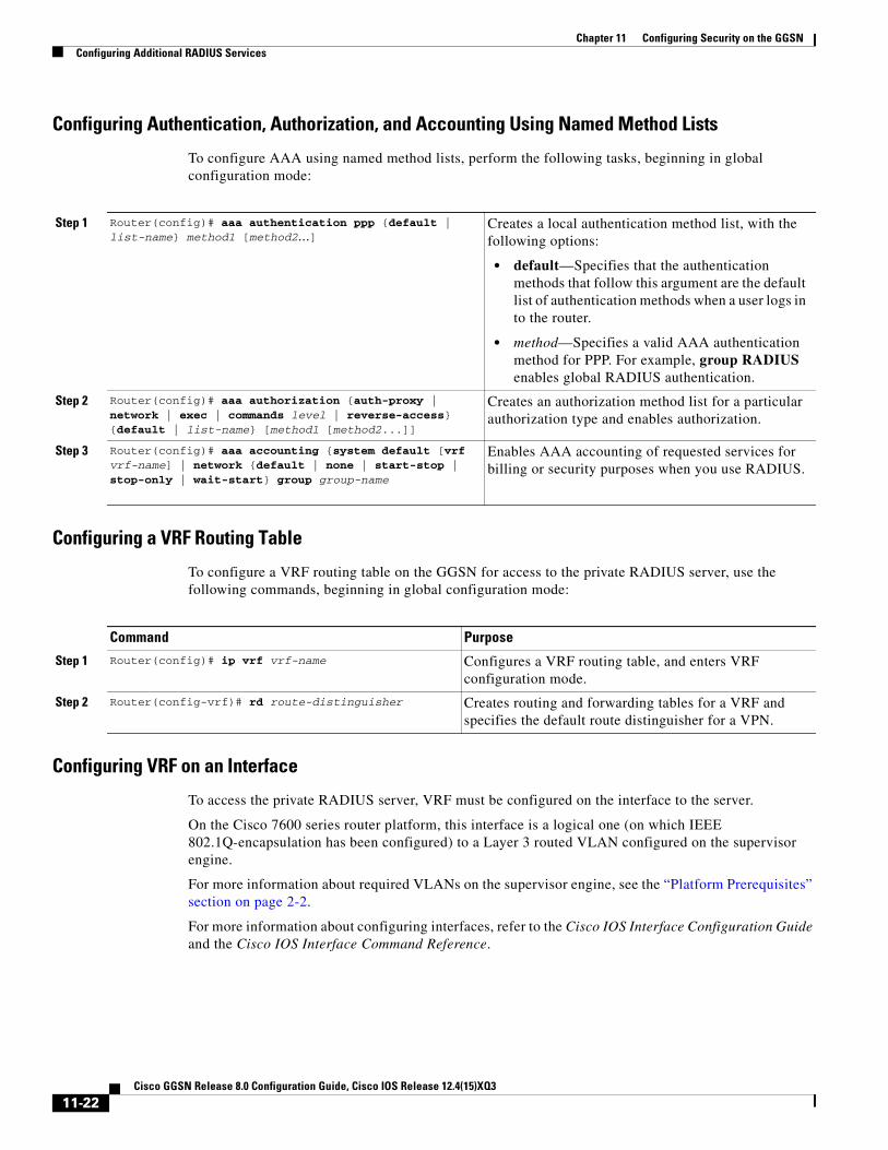
Chapter 11 Configuring Security on the GGSNConfiguring Additional RADIUS Services
Configuring Authentication, Authorization, and Accounting Using Named Method Lists
To configure AAA using named method lists, perform the following tasks, beginning in global configuration mode:
Configuring a VRF Routing Table
To configure a VRF routing table on the GGSN for access to the private RADIUS server, use the following commands, beginning in global configuration mode:
Configuring VRF on an Interface
To access the private RADIUS server, VRF must be configured on the interface to the server.
On the Cisco 7600 series router platform, this interface is a logical one (on which IEEE 802.1Q-encapsulation has been configured) to a Layer 3 routed VLAN configured on the supervisor engine.
For more information about required VLANs on the supervisor engine, see the “Platform Prerequisites” section on page 2-2.
For more information about configuring interfaces, refer to the Cisco IOS Interface Configuration Guide and the Cisco IOS Interface Command Reference.
Step 1 Router(config)# aaa authentication ppp {default | list-name} method1 [method2...]
Creates a local authentication method list, with the following options:
• default—Specifies that the authentication methods that follow this argument are the default list of authentication methods when a user logs in to the router.
• method—Specifies a valid AAA authentication method for PPP. For example, group RADIUS enables global RADIUS authentication.
Step 2 Router(config)# aaa authorization {auth-proxy | network | exec | commands level | reverse-access} {default | list-name} [method1 [method2...]]
Creates an authorization method list for a particular authorization type and enables authorization.
Step 3 Router(config)# aaa accounting {system default [vrf vrf-name] | network {default | none | start-stop | stop-only | wait-start} group group-name
Enables AAA accounting of requested services for billing or security purposes when you use RADIUS.
Command Purpose
Step 1 Router(config)# ip vrf vrf-name Configures a VRF routing table, and enters VRF configuration mode.
Step 2 Router(config-vrf)# rd route-distinguisher Creates routing and forwarding tables for a VRF and specifies the default route distinguisher for a VPN.
11-22Cisco GGSN Release 8.0 Configuration Guide, Cisco IOS Release 12.4(15)XQ3

Chapter 11 Configuring Security on the GGSNConfiguring Additional RADIUS Services
Configuring 802.1Q-Encapsulated Subinterfaces
To configure a subinterface that supports IEEE 802.1Q encapsulation to the associated VLAN on the supervisor engine, use the following commands, beginning in global configuration mode:
Configuring VRF Under an Access Point for Access to the Private RADIUS Server
After you have completed the prerequisite configuration tasks, you can configure access to a RADIUS server with a tunnel or without a tunnel.
The following sections describe the different methods you can use to configure access a RADIUS server:
• Configuring Access to a RADIUS Server Without a Tunnel
• Configuring Access to a RADIUS Server With a Tunnel
Configuring Access to a RADIUS Server Without a Tunnel
To configure access to the RADIUS server without a tunnel, you need to configure the vrf access point configuration command.
Note To configure access to a RADIUS server in the GPRS access point list, use the following commands, beginning in global configuration mode:
Command Purpose
Step 1 Router(config)# interface gigabitethernet slot/port.subinterface-number
Specifies the subinterface on which IEEE 802.1Q will be used.
Step 2 Router(config-if)# encapsulation dot1q vlanid Defines the encapsulation format as IEEE 802.1Q (dot1q), and specifies the VLAN identifier.
Step 3 Router(config-if)# ip address ip-address mask Sets a primary IP address for an interface.
Command Purpose
Step 1 Router(config)# gprs access-point-list list-name Specifies a name for a new access point list, or references the name of the existing access point list, and enters access-point list configuration mode.
Step 2 Router(config-ap-list)# access-point access-point-index
Specifies an index number for a new access point definition, or references an existing access point definition, and enters access point configuration mode.
Step 3 Router(config-access-point)# access-point-name apn-name
Specifies the network (or domain) name for a PDN that users can access from the GGSN at a defined access point.
Note The apn-name must match the APN that has been provisioned at the MS, HLR, and DNS server.
11-23Cisco GGSN Release 8.0 Configuration Guide, Cisco IOS Release 12.4(15)XQ3

Chapter 11 Configuring Security on the GGSNConfiguring Additional RADIUS Services
Configuring Access to a RADIUS Server With a Tunnel
If you have only a single interface to a RADIUS server from which you need to access one or more private RADIUS servers, you can configure an IP tunnel to access those private servers.
To configure access to the RADIUS server using a tunnel, perform the following tasks:
• Configuring the Private RADIUS Server Access Point (Required)
• Configuring the IP Tunnel (Required)
Step 4 Router(config-access-point)# aaa-group authentication server-group
Specifies a default AAA server group and assigns the type of AAA services to be supported by the server group for a particular access point on the GGSN, where:
• authentication—Assigns the selected server group for authentication services on the APN.
• server-group—Specifies the name of a AAA server group to be used for AAA services on the APN.
Note The name of the AAA server group that you specify must correspond to a server group that you configure using the aaa group server command.
Step 5 Router(config-access-point)# access-mode non-transparent
Specifies for the GGSN to act as a proxy for authentication.
Step 6 Router(config-access-point)# ip-address-pool radius-client
Specifies for the RADIUS server to provide the IP address pool for the current access point.
Note If you are using a dynamic address allocation method, then you must configure this command according to the appropriate IP address pool source.
Step 7 Router(config-access-point)# vrf vrf-name Configures VPN routing and forwarding at a GGSN access point, and associates the access point with a particular VRF instance.
Note The vrf-name argument should match the name of the VRF that you configured using the ip vrf command in the “Configuring Authentication, Authorization, and Accounting Using Named Method Lists” section on page 11-22.
Step 8 Router(config-access-point)# exit Exits access point configuration mode.
Command Purpose
11-24Cisco GGSN Release 8.0 Configuration Guide, Cisco IOS Release 12.4(15)XQ3

Chapter 11 Configuring Security on the GGSNConfiguring Additional RADIUS Services
Configuring the Private RADIUS Server Access PointTo configure access to a private RADIUS server in the GPRS access point list, use the following commands, beginning in global configuration mode:
Command Purpose
Step 1 Router(config)# gprs access-point-list list-name Specifies a name for a new access point list, or references the name of the existing access point list, and enters access-point list configuration mode.
Step 2 Router(config-ap-list)# access-point access-point-index
Specifies an index number for a new access point definition, or references an existing access point definition, and enters access point configuration mode.
Step 3 Router(config-access-point)# access-point name apn-name
Specifies the access point network ID, which is commonly an Internet domain name.
Note The apn-name must match the APN that has been provisioned at the mobile station (MS), home location register (HLR), and DNS server.
Step 4 Router(config-access-point)# access-mode {transparent | non-transparent}
(Optional) Specifies whether the GGSN requests user authentication at the access point. The available options are:
• transparent—No security authorization or authentication is requested by the GGSN for this access point. This is the default value.
• non-transparent—GGSN acts as a proxy for authenticating.
Step 5 Router(config-access-point)# access-type real Specifies an APN type that corresponds to an interface to an external network on the GGSN. Real is the default value.
11-25Cisco GGSN Release 8.0 Configuration Guide, Cisco IOS Release 12.4(15)XQ3

Chapter 11 Configuring Security on the GGSNConfiguring Additional RADIUS Services
Configuring the IP Tunnel
When you configure a tunnel, you might consider using loopback interfaces as the tunnel endpoints instead of real interfaces because loopback interfaces are always up.
To configure an IP tunnel to a private network, use the following commands, beginning in global configuration mode:
Step 6 Router(config-access-point)# ip-address-pool {dhcp-proxy-client | radius-client | local pool-name | disable}
(Optional) Specifies a dynamic address allocation method using IP address pools for the current access point. The available options are:
• dhcp-proxy-client—DHCP server provides the IP address pool.
• radius-client—RADIUS server provides the IP address pool.
• local—Specifies that a local pool provides the IP address. This option requires that the address range be configured using the aggregate access point configuration command and that a local pool has been configured using the ip local pool global configuration command.
• disable—Turns off dynamic address allocation.
Note If you are using a dynamic address allocation method, then you must configure this command according to the appropriate IP address pool source.
Step 7 Router(config-access-point)# vrf vrf-name Configures VPN routing and forwarding at a GGSN access point and associates the access point with a particular VRF instance.
Step 8 Router(config-access-point)# exit Exits access point configuration mode.
Command Purpose
Command Purpose
Step 1 Router(config)# interface tunnel number Configures a logical tunnel interface number.
Step 2 Router(config-if)# ip vrf forwarding vrf-name Associates a VRF instance with the interface.
Step 3 Router(config-if)# ip address ip-address mask [secondary]
Specifies an IP address for the tunnel interface.
Note This IP address is not used in any other part of the GGSN configuration.
Step 4 Router(config-if)# tunnel source {ip-address | type number}
Specifies the IP address (or interface type and port or card number) of the interface to the RADIUS server or a loopback interface.
Step 5 Router(config-if)# tunnel destination {hostname | ip-address}
Specifies IP address (or host name) of the private network that you can access from this tunnel.
11-26Cisco GGSN Release 8.0 Configuration Guide, Cisco IOS Release 12.4(15)XQ3

Chapter 11 Configuring Security on the GGSNConfiguring Additional RADIUS Services
Configuring a Route to the RADIUS Server Using VRF
Be sure a route exists between the VRF instance and the RADIUS server. You can verify connectivity by using the ping command from the VRF to the RADIUS server. To configure a route, you can use a static route or a routing protocol.
Configuring a Static Route Using VRF
To configure a static route using, use the following command, beginning in global configuration mode:
Verifying a Static Route Using VRF
To verify the static VRF route that you configured, use the show ip route vrf privileged EXEC command as shown in the following example:
GGSN# show ip route vrf vpn1 static
172.16.0.0/16 is subnetted, 1 subnetsC 172.16.0.1 is directly connected, Ethernet5/1C 10.100.0.3/8 is directly connected, Virtual-Access5
Command PurposeRouter(config)# ip route vrf vrf-name prefix mask [next-hop-address] [interface {interface-number}] [global] [distance] [permanent] [tag tag]
Configures a static IP route, where:
• vrf-name—Specifies the name of the VPN routing/forwarding (VRF) instance for the static route.
• prefix—Specifies the IP route prefix for the destination.
• mask—Specifies the prefix mask for the destination.
• next-hop-address—Specifies the IP address of the next hop that can be used to reach the destination network.
• interface interface-number—Specifies the network interface type and interface number that can be used to reach the destination network.
• global—Specifies that the given next hop address is in the non-VRF routing table.
• distance—Specifies an administrative distance for the route.
• permanent—Specifies that the route will not be removed, even if the interface shuts down.
• tag tag—Specifies a tag value that can be used as a “match” value for controlling redistribution via route maps.
11-27Cisco GGSN Release 8.0 Configuration Guide, Cisco IOS Release 12.4(15)XQ3
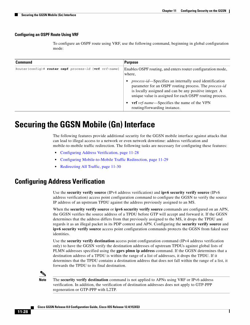
Chapter 11 Configuring Security on the GGSNSecuring the GGSN Mobile (Gn) Interface
Configuring an OSPF Route Using VRF
To configure an OSPF route using VRF, use the following command, beginning in global configuration mode:
Securing the GGSN Mobile (Gn) InterfaceThe following features provide additional security for the GGSN mobile interface against attacks that can lead to illegal access to a network or even network downtime: address verification and mobile-to-mobile traffic redirection. The following tasks are necessary for configuring these features:
• Configuring Address Verification, page 11-28
• Configuring Mobile-to-Mobile Traffic Redirection, page 11-29
• Redirecting All Traffic, page 11-30
Configuring Address VerificationUse the security verify source (IPv4 address verification) and ipv6 security verify source (IPv6 address verification) access point configuration command to configure the GGSN to verify the source IP address of an upstream TPDU against the address previously assigned to an MS.
When the security verify source or ipv6 security verify source commands are configured on an APN, the GGSN verifies the source address of a TPDU before GTP will accept and forward it. If the GGSN determines that the address differs from that previously assigned to the MS, it drops the TPDU and regards it as an illegal packet in its PDP context and APN. Configuring the security verify source and ipv6 security verify source access point configuration commands protects the GGSN from faked user identities.
Use the security verify destination access point configuration command (IPv4 address verification only) to have the GGSN verify the destination addresses of upstream TPDUs against global lists of PLMN addresses specified using the gprs plmn ip address command. If the GGSN determines that a destination address of a TPDU is within the range of a list of addresses, it drops the TPDU. If it determines that the TPDU contains a destination address that does not fall within the range of a list, it forwards the TPDU to its final destination.
Note The security verify destination command is not applied to APNs using VRF or IPv6 address verification. In addition, the verification of destination addresses does not apply to GTP-PPP regeneration or GTP-PPP with L2TP.
Command PurposeRouter(config)# router ospf process-id [vrf vrf-name] Enables OSPF routing, and enters router configuration mode,
where,
• process-id—Specifies an internally used identification parameter for an OSPF routing process. The process-id is locally assigned and can be any positive integer. A unique value is assigned for each OSPF routing process.
• vrf vrf-name—Specifies the name of the VPN routing/forwarding instance.
11-28Cisco GGSN Release 8.0 Configuration Guide, Cisco IOS Release 12.4(15)XQ3

Chapter 11 Configuring Security on the GGSNSecuring the GGSN Mobile (Gn) Interface
To configure IPv4 address verification on an access point, use the following command in access-point configuration mode:
Note Both the verification of IPv4 destination addresses and source addresses can be configured on an APN.
To configure IPv6 source address verification on an access point, use the following command in access-point configuration mode:
Configuring Mobile-to-Mobile Traffic RedirectionMobile-to-mobile traffic enters and exits through a Gn interface. Therefore, it is switched by the GGSN without ever going through a Gi interface on the network side. Because of this, firewalls deployed on the network side of a GGSN do not have an opportunity to verify this level of traffic.
Use the redirect intermobile ip access-point command to redirect mobile-to-mobile traffic to an external device (such as an external firewall) for verification.
Note On the Cisco 7600 series internet router platform, the mobile-to-mobile redirection feature requires that policy based routing (PBR) is configured on the supervisor engine and incoming VLAN interface from the Cisco SAMI, and that the next hop to route the packets that match the criteria is set using the set ip next-hop command.
Command PurposeRouter(config-access-point)# security verify {source | destination}
(Optional) Specifies that the GGSN verify the source or destination address in TPDUs received from a Gn interface.
Command Purpose
Router(config-access-point)# ipv6 security verify source (Optional) Configures the GGSN to verify the IPv6 source address of an upstream TPDU against the address previously assigned to an MS, use the ipv6 security verify source command in access-point configuration mode.
Command Purpose
Router(config-access-point)# redirect intermobile ip ip address
(Optional) Configures the GGSN to redirect all IPv4 mobile-to-mobile traffic to an external device.
Router(config-access-point)# ipv6 redirect intermobile ipv6-address
(Optional) Configures the GGSN to redirect all IPv6 mobile-to-mobile traffic to an external IPv6 device.
11-29Cisco GGSN Release 8.0 Configuration Guide, Cisco IOS Release 12.4(15)XQ3

Chapter 11 Configuring Security on the GGSNConfiguring Simultaneous Broadcast and Wait Accounting
Note Redirection of intermobile traffic does not occur on an ingress APN unless the TPDUs are exiting the same APN. In addition, redirection of TPDUs tunneled by L2TP from the ingress APN to the LNS of the PDN does not occur.
Redirecting All TrafficThe redirect all traffic feature enables you to do the following:
• Redirect all packets to a specified destination regardless of whether the destination address belongs to a mobile station (MS) on the same GGSN or not. If redirecting traffic using the Mobile-to-Mobile Redirect feature, only packets for which the destination address belongs to an MS that is active on the same GGSN can be redirected. If the receiving MS has no PDP context in the GGSN where the sending MS PDP context is created, the packets are dropped.
• Redirect all traffic to a specific destination when aggregate routes are configured.
To redirect all traffic to a specific IP address, issue the following command while in access-point configuration mode:
Configuring Simultaneous Broadcast and Wait AccountingWith Cisco GGSN Release 8.0 and later, broadcast and wait accounting can be configured to work together. The wait accounting feature is configured at the APN level, while broadcast accounting is specified at the AAA method level.
Broadcast accounting sends start, stop and interim accounting records to all the server groups configured in a method list. Within a server group, the accounting records are sent to the first active server. If the active server cannot be reached, then the accounting records are sent to the next server within a group.
Additionally, one or more server groups within a method list can be configured as “mandatory,” meaning that a server from that server group has to respond to the Accounting Start message. The APN-level wait accounting ensures that an accounting response has been received from all mandatory server groups before the PDP context is established.
The advantages of broadcasat and wait accounting together include:
• Accounting records are sent to multiple servers and once the entry is made, the user can start using different services.
• Records are sent to multiple AAA servers serve for redundancy purposes.
• A PDP context is established only when a valid Accounting Start record has been received by all essential servers, avoiding information loss.
• Broadcast records can be sent to as many as 10 server groups within a method-list.
Command Purpose
Router(config-access-point)# redirect all ip ip address (Optional) Configures the GGSN to redirect all IPv4 traffic to an external device.
Router(config-access-point)# ipv6 redirect all intermobile ipv6-address
(Optional) Configures the GGSN to redirect all IPv6 traffic to an external IPv6 device.
11-30Cisco GGSN Release 8.0 Configuration Guide, Cisco IOS Release 12.4(15)XQ3

Chapter 11 Configuring Security on the GGSNConfiguring Simultaneous Broadcast and Wait Accounting
When configuring broadcast and wait accounting together, note the following:
• Under the method list configuration, the mandatory keyword is available only if broadcast accounting is configured.
• If wait accounting is not required, broadcast accounting to all server groups is available without any mandatory groups defined.
• If you do not specify any mandatory server groups when configuring broadcast accounting, wait accounting will function as it does in Cisco GGSN Release 7.0 and prior releases.
• Wait accounting does not apply to PPP PDP contexts.
• A PDP is successfully created only when a Accounting response is received from all the mandatory servers.
• The periodic timer starts when an Accounting Response (PDP creation) is received.
Note More than one server-group can be defined as a mandatory server-group in a method list.
To configure broadcast and wait accounting on the GGSN, complete the following tasks, beginning in global configuration mode:
Command Purpose
Step 1 Router(config)# aaa accounting network methodlist-name Enables authentication, authorization, and accounting (AAA) accounting of requested services for billing or security purposes when you use RADIUS.
Step 2 Router(cfg-acct-mlist)# action-type {start-stop | stop-only | none}
Type of action to be performed on accounting records. Possible values are:
• start-stop—Sends a “start” accounting notice at the beginning of a process and a “stop” accounting notice at the end of a process.
• stop-only—Sends a “stop” accounting notice at the end of the requested user process.
• none—Disables accounting services on this line or interface.
Step 3 Router(cfg-acct-mlist)# broadcast (Optional) Enables sending accounting records to multiple AAA servers. Simultaneously sends accounting records to the first server in each group. If the first server is unavailable, failover occurs using the backup servers defined within that group.
Step 4 Router(cfg-acct-mlist)# group {server-group} [mandatory]
Specifies the server group. Optionally, specify mandatory to define this server group as mandatory. If a server group is mandatory, a server from the server group has to respond to the Accounting Start message.
Note Up to 10 server groups can be defined within a method list.
Step 5 Router(cfg-acct-mlist)# exit Exits from accounting method list mode.
11-31Cisco GGSN Release 8.0 Configuration Guide, Cisco IOS Release 12.4(15)XQ3

Chapter 11 Configuring Security on the GGSNPeriodic Accounting Timer
Periodic Accounting TimerThe Cisco IOS software supports a global AAA configuration command that enables the sending of periodic accounting records for AAA sessions. However, the GGSN does not use this configuration to send periodic accounting records for PDP contexts.
With Cisco GGSN Release 8.0 and later, the periodic accounting timer interval value is obtained using one of the following:
• Configured periodic timer at an APN level
• Configured periodic timer at the GGSN global configuration level
• An accounting-interim interval attribute in access-accept messages
When these configurations exist, “interim” type accounting records are sent at the configured interval for the applicable PDP contexts. The following precedence applies:
• The APN-level configuration
• GGSN global configuration
• Attribute 85 (in access-accept messages)
Note If the value is obtained through Attribute 85 in an access-accept message, the GGSN verifies that the minimum and maximum values are within range configured on the GGSN, and if not, the attribute is ignored. Additionally, if accounting is not enabled on the APN, Attribute 85 is ignored.
When the GGSN sends an interim update accounting (IAU) record, the periodic timer is reset so that next periodic accounting record will be sent after the periodic interval expires, starting from the instance when the IAU record is sent.
This limits the RADIUS accounting traffic as both types of records contain the same information. However, after a failover, the records sent out will be aligned with the original START record.
Caution If the aaa accounting update periodic command is configured on the GGSN, and GGSN-level periodic accounting is not configured, the GGSN will send interim accounting records after the Accounting Start message has been sent to AAA server. This might have adverse effects on the GGSN, therefore ensure that the aaa accounting update periodic command has not been configured.
Step 1 Router(config)# gprs access-point-list list_name Configures an access point list that you use to define public data network (PDN) access points on the GGSN.
Step 2 Router(config-ap-list)#access-point access-point-index Specifies an access point number and enters access point configuration mode.
Step 3 Router(config-access-point)#aaa-group accounting method-list name
Specifies an accounting server group.
Step 4 Router(config-access-point)# gtp-response-message wait-accounting
Configure APN to wait for a RADIUS accounting response before sending a Create PDP Context response to the SGSN.
Command Purpose
11-32Cisco GGSN Release 8.0 Configuration Guide, Cisco IOS Release 12.4(15)XQ3

Chapter 11 Configuring Security on the GGSNPeriodic Accounting Timer
When configuring periodic accounting timers on the GGSN, note the following:
• Timers are supported for PPP-Regen, IPv4, and IPv6 PDP’s. Timers do not apply to do PPP PDPs.
• The send/receive byte counts for a PDP is reset to 0 upon failover.
• Redundant systems should have their clocks synchronised with a mechanism such as NTP to ensure that their timer intervals to be accurate
• Periodic accounting on a redundant configuration maintains intervals across switchovers.
• A timer is initiated only on successful PDP creation, for example, in the case of wait accounting after a successful accounting response has been received.
Configuring a Default GGSN Periodic Accounting TimerTo enable a default periodic accounting value, to use for all APNs, use the following command while in global configuration mode:
Configuring an APN-Level Periodic Accounting TimerTo configure the periodic accounting timer on an APN, complete the following tasks, beginning in global configuration mode:
Note AAA global configuration value (aaa accounting update periodic minutes) will be ignored always. Also, unless APN accounting is enabled, the periodic accounting will not take effect regardless of how it is configured.
Command Purpose
Router(config)# gprs default aaa-accounting interim periodic minutes
Configures a default periodic accounting timer on the GGSN. Valid values are 15 to 71582. The default is no periodic accounting timer is configured globally.
Command Purpose
Step 1 Router(config)# gprs access-point-list list_name Configures an access point list.
Step 2 Router(config-ap-list)#access-point access-point-index Specifies an access point number and enters access point configuration mode.
Step 3 Router(config-access-point)#aaa-accounting interim periodic minutes
Configures a periodic accounting timer on an APN. Valid values are 15 to 71582. The default is no periodic accounting timer is configured at the APN level.
Step 4 Router(config-access-point)#aaa-accounting interim periodic radius
Enables the APN to accept the periodic accounting value (Attribute 85) sent by RADIUS.
11-33Cisco GGSN Release 8.0 Configuration Guide, Cisco IOS Release 12.4(15)XQ3

Chapter 11 Configuring Security on the GGSNConfiguration Examples
Configuration ExamplesThis section includes the following configuration examples for security on the GGSN:
• AAA Security Configuration Example, page 11-34
• RADIUS Server Global Configuration Example, page 11-34
• RADIUS Server Group Configuration Example, page 11-35
• RADIUS Response Message Configuration Example, page 11-36
• Address Verification and Mobile-to-Mobile Traffic Redirection Example, page 11-37
• “Periodic Accounting Timer Example” section on page 11-40
AAA Security Configuration ExampleThe following example shows how to enable AAA security globally on the router and how to specify global RADIUS authentication and authorization:
! Enables AAA globallyaaa new-model!! Creates a local authentication list for use on! serial interfaces running PPP using RADIUS!aaa authentication ppp abc group abc!! Enables authorization and creates an authorization ! method list for all network-related service requests! and enables authorization using a RADIUS server!aaa authorization network network abc group abc
For more information about configuring AAA, refer to the Cisco IOS Security Configuration Guide and Cisco IOS Security Command Reference publications.
RADIUS Server Global Configuration ExampleThe following example shows how to globally configure RADIUS server communication on the router:
! Specifies a global RADIUS server host at IP address 10.100.0.2! Port 1645 is destination port for authentication requests! Port 1646 is the destination port for accounting requests! Specifies the key “abc” for this radius host only!radius-server host 10.100.0.2 auth-port 1645 acct-port 1646 key abc!! Sets the authentication and encryption key to mykey for all ! RADIUS communications between the router and the RADIUS daemon!radius-server key mykey
Note Although you can configure the radius-server host command multiple times, the Cisco IOS software supports only one RADIUS server at the same IP address.
11-34Cisco GGSN Release 8.0 Configuration Guide, Cisco IOS Release 12.4(15)XQ3

Chapter 11 Configuring Security on the GGSNConfiguration Examples
For more information about configuring RADIUS security, refer to the Cisco IOS Security Configuration Guide and Cisco IOS Security Command Reference publications.
RADIUS Server Group Configuration ExampleThe following configuration example defines four AAA server groups on the GGSN: abc, abc1, abc2, and abc3, shown by the aaa group server commands.
Using the gprs default aaa-group command, two of these server groups are globally defined as default server groups: abc2 for authentication, and abc3 for accounting.
At access-point 1, which is enabled for authentication, the default global authentication server group of abc2 is overridden and the server group named abc is designated to provide authentication services on the APN. Notice that accounting services are not explicitly configured at that access point, but are automatically enabled because authentication is enabled. Because there is a globally defined accounting server-group defined, the server named abc3 will be used for accounting services.
At access-point 4, which is enabled for accounting using the aaa-accounting enable command, the default accounting server group of abc3 is overridden and the server group named abc1 is designated to provide accounting services on the APN.
Access-point 5 does not support any AAA services because it is configured for transparent access mode.
! Enables AAA globally!aaa new-model!! Defines AAA server groups! aaa group server radius abc server 10.2.3.4 auth-port 1645 acct-port 1646 server 10.6.7.8 auth-port 1645 acct-port 1646aaa group server radius abc1 server 10.10.0.1 auth-port 1645 acct-port 1646aaa group server radius abc2 server 10.2.3.4 auth-port 1645 acct-port 1646 server 10.10.0.1 auth-port 1645 acct-port 1646aaa group server abc3 server 10.6.7.8 auth-port 1645 acct-port 1646 server 10.10.0.1 auth-port 1645 acct-port 1646!! Configures AAA authentication! and authorization!aaa authentication ppp abc group abcaaa authentication ppp abc2 group abc2aaa authorization network abc group abc aaa accounting network abc start-stop group abcaaa accounting network abc1 start-stop group abc1aaa accounting network abc2 start-stop group abc2aaa accounting network abc3 start-stop group abc3!gprs access-point-list gprs access-point 1 access-mode non-transparent access-point-name www.pdn1.com!! Specifies a RADIUS server group! for use by the GGSN to authenticate! mobile users at this access point!
11-35Cisco GGSN Release 8.0 Configuration Guide, Cisco IOS Release 12.4(15)XQ3

Chapter 11 Configuring Security on the GGSNConfiguration Examples
aaa-group authentication abc! access-point 4 access-point-name www.pdn2.com!! Enables AAA accounting services! aaa-accounting enable!! Specifies a RADIUS server group! for use by the GGSN for accounting! services at this access point
aaa-group accounting abc1! access-point 5 access-point-name www.pdn3.com!! Configures default AAA server ! groups for the GGSN for authentication! and accounting services!gprs default aaa-group authentication abc2gprs default aaa-group accounting abc3!! Configures global RADIUS server hosts! and specifies destination ports for ! authentication and accounting requests!radius-server host 10.2.3.4 auth-port 1645 acct-port 1646 non-standardradius-server host 10.6.7.8 auth-port 1645 acct-port 1646 non-standardradius-server host 10.10.0.1 auth-port 1645 acct-port 1646 non-standardradius-server key ggsntel
Note Although you can configure the radius-server host command multiple times, the Cisco IOS software supports only one RADIUS server at the same IP address.
RADIUS Response Message Configuration ExampleThe following example globally configures the GGSN to wait for a RADIUS accounting response from the RADIUS server before sending a Create PDP Context response to the SGSN. The GGSN waits for a response for PDP context requests received across all access points, except access-point 1. RADIUS response message waiting has been overridden at access-point 1 by using the no gtp response-message wait-accounting command:
! Enables AAA globally!aaa new-model!! Defines AAA server group! aaa group server radius abc server 10.2.3.4 auth-port 1645 acct-port 1646 server 10.6.7.8 auth-port 1645 acct-port 1646!! Configures AAA authentication! and authorization!aaa authentication ppp abc group abc
11-36Cisco GGSN Release 8.0 Configuration Guide, Cisco IOS Release 12.4(15)XQ3

Chapter 11 Configuring Security on the GGSNConfiguration Examples
aaa authorization network abc group abcaaa accounting network abc start-stop group abc!gprs access-point-list gprs access-point 1 access-mode non-transparent access-point-name www.pdn1.com aaa-group authentication abc!! Disables waiting for RADIUS response! message at APN 1! no gtp response-message wait-accounting exitaccess-point 2 access-mode non-transparent access-point-name www.pdn2.com aaa-group authentication abc!! Enables waiting for RADIUS response! messages across all APNs (except APN 1)!gprs gtp response-message wait-accounting!! Configures global RADIUS server hosts! and specifies destination ports for ! authentication and accounting requests!radius-server host 10.2.3.4 auth-port 1645 acct-port 1646 non-standardradius-server host 10.6.7.8 auth-port 1645 acct-port 1646 non-standardradius-server key ggsntel
Address Verification and Mobile-to-Mobile Traffic Redirection ExampleThe following examples show how to enable IPv4 address verification and specify that IPv4 mobile-to-mobile traffic be redirected to an external device.
GGSN Configurationservice gprs ggsn!hostname t7600-7-2!ip cef!ip vrf vpn4 description abc_vrf rd 104:4!!interface Loopback2 description USED FOR DHCP2 - range IN dup prot range ip address 111.72.0.2 255.255.255.255!interface Loopback100 description GPRS GTP V-TEMPLATE IP ADDRESS ip address 9.9.9.72 255.255.255.0!interface GigabitEthernet0/0 no ip address!
11-37Cisco GGSN Release 8.0 Configuration Guide, Cisco IOS Release 12.4(15)XQ3

Chapter 11 Configuring Security on the GGSNConfiguration Examples
interface GigabitEthernet0/0.2 description Ga/Gn Interface encapsulation dot1Q 101 ip address 10.1.1.72 255.255.255.0 no cdp enable!interface GigabitEthernet0/0.3 encapsulation dot1Q 103 ip vrf forwarding vpn4 ip address 10.1.3.72 255.255.255.0 no cdp enable!interface GigabitEthernet0/0.95 description CNR and CAR encapsulation dot1Q 95 ip address 10.2.25.72 255.255.255.0!interface Virtual-Template1 description GTP v-access ip unnumbered Loopback100 encapsulation gtp gprs access-point-list gprs!! In case the ms is on another SAMI GGSNip route vrf vpn4 0.0.0.0 0.0.0.0 10.1.3.1!gprs access-point-list gprs access-point 7 access-point-name ms_redirect.com ip-address-pool dhcp-proxy-client aggregate auto dhcp-server 10.2.25.90 dhcp-gateway-address 111.72.0.2 vrf vpn4 ! In case the ms is on this GGSN. redirect intermobile ip 10.1.3.1 !
Supervisor Engine Configurationhostname 7600-a
interface FastEthernet9/15 description OUT to Firewall no ip address duplex half switchport switchport access vlan 162!interface FastEthernet9/16 description In from Firewall no ip address switchport switchport access vlan 163!interface Vlan103 description Vlan to GGSN redirect to FW ip address 10.1.3.1 255.255.255.0 ip policy route-map REDIRECT-TO-FIREWALL!interface Vlan162 ip address 162.1.1.1 255.255.255.0!interface Vlan163
11-38Cisco GGSN Release 8.0 Configuration Guide, Cisco IOS Release 12.4(15)XQ3

Chapter 11 Configuring Security on the GGSNConfiguration Examples
ip address 163.1.1.1 255.255.255.0!ip route 111.72.0.0 255.255.0.0 10.1.3.72ip route 111.73.0.0 255.255.0.0 10.1.3.73ip route 111.74.0.0 255.255.0.0 10.1.3.74ip route 111.75.0.0 255.255.0.0 10.1.3.75ip route 111.76.0.0 255.255.0.0 10.1.3.76!access-list 102 permit ip any any!route-map REDIRECT-TO-FIREWALL permit 10 match ip address 102 set ip next-hop 162.1.1.11!
Access to a Private RADIUS Server Using VRF Configuration ExampleThe following examples shows an example of configuring access to a private RADIUS server using VRF.
GGSN Configurationaaa new-model!
aaa group server radius vrf_aware_radius server-private 99.100.0.2 auth-port 1645 acct-port 1646 key cisco ip vrf!aaa authentication ppp vrf_aware_radius group vrf_aware_radiusaaa authorization network default local group radius aaa authorization network vrf_aware_radius group vrf_aware_radius aaa accounting network vrf_aware_radius start-stop group vrf_aware_radiusaaa session-id common
!ip vrf vpn2 rd 101:1!interface Loopback1 ip address 150.1.1.72 255.255.0.0!interface Tunnel2 ip vrf forwarding vpn2 ip address 80.80.72.72 255.255.255.0 tunnel source 150.1.1.72 tunnel destination 167.2.1.12!ip local pool vpn2_pool 100.72.0.1 100.72.255.255 group vpn2ip route vrf vpn2 0.0.0.0 0.0.0.0 Tunnel2!gprs access-point-list gprs access-point 1 access-point-name apn.vrf2.com access-mode non-transparent aaa-group authentication vrf_aware_radius aaa-group accounting vrf_aware_radius ip-address-pool local vpn2_pool aggregate 100.72.0.0 255.255.0.0 vrf vpn2 !
11-39Cisco GGSN Release 8.0 Configuration Guide, Cisco IOS Release 12.4(15)XQ3

Chapter 11 Configuring Security on the GGSNConfiguration Examples
Supervisor Engine Configuration...!interface FastEthernet9/5 switchport switchport access vlan 167!
interface Vlan167 ip address 167.1.1.1 255.255.0.0!ip route 150.1.1.72 255.255.255.255 10.1.1.72ip route 167.2.0.0 255.255.0.0 167.1.1.12!...
Periodic Accounting Timer ExampleThe following example shows a period accounting timer configured at the APN level and globally.
gprs default aaa-accounting interim periodic 60 ! gprs access-point-list APLIST access-point 100 access-point-name peracct.com access-mode non-transparent aaa-accounting interim update aaa-accounting interim periodic 15 aaa-group authentication radaccess aaa-group accounting default ip-address-pool radius-client gtp response-message wait-accounting !
11-40Cisco GGSN Release 8.0 Configuration Guide, Cisco IOS Release 12.4(15)XQ3

Cisco GGSN Release 8.0
C H A P T E R12
Configuring Dynamic Addressing on the GGSNThis chapter describes how to configure dynamic IP addressing on the gateway GRPS support node (GGSN).
Note The tasks in this chapter apply to IPv4 PDP contexts only. For information on IPv6 addressing, see Chapter 4, “Configuring IPv6 PDP Support on the GGSN.”
For a complete description of the GGSN commands in this chapter, refer to the Cisco GGSN Command Reference for the Cisco GGSN release you are using. To locate documentation of other commands that appear in this chapter, use the command reference master index or search online.
This chapter includes the following sections:
• Overview of Dynamic IP Addressing on the GGSN, page 12-1
• Configuring DHCP on the GGSN, page 12-2
• Configuring MS Addressing via Local Pools on the GGSN, page 12-10
• Configuring MS Addressing via RADIUS, page 12-12
• Configuring IP Overlapping Address Pools, page 12-12
• Configuring the NBNS and DNS Address for an APN, page 12-16
Overview of Dynamic IP Addressing on the GGSNThere are three methods for configuring the GGSN to assign IP addresses to mobile station users who need to access the public data network (PDN): Dynamic Host Configuration Protocol (DHCP) allocation, Remote Authentication Dial-In User Service (RADIUS) allocation, and local IP address pool allocation configured at the access point name (APN) or downloaded .
A method of dynamic IP addressing can be configured either globally or at the access-point configuration level.
12-1Configuration Guide, Cisco IOS Release 12.4(15)XQ3

Chapter 12 Configuring Dynamic Addressing on the GGSNConfiguring DHCP on the GGSN
Be sure that the following configuration guidelines are met to support the type of IP address allocation in use on your network:
• DHCP IP address allocation
– Be sure that you configure the scope of the addresses to be allocated on the same subnet as the loopback interface.
– Do not configure an IP address for users on the RADIUS server.
– Specify the peer default ip address dhcp command at the PPP virtual template interface.
– Specify the aaa authorization network method_list none command on the GGSN.
• RADIUS IP address allocation
– Be sure that users are configured on the RADIUS server using the complete username@domain format.
– Specify the no peer default ip address command at the PPP Virtual Template interface.
– For more information about configuring RADIUS services on the GGSN, see the “Configuring Security on the GGSN” chapter in this book.
• Local pool IP address allocation
– Be sure to configure a local pool using the ip local pool command.
– Specify the aaa authorization network method_list none command on the GGSN.
– Specify the peer default ip address pool pool-name command.
Note On the Cisco 7600 platform, dynamic address allocation using the DHCP or RADIUS server methods requires that the DHCP or RADIUS server be Layer 3 routeable from the supervisor engine.
Configuring DHCP on the GGSNYou can use local DHCP services within the Cisco IOS software, or you can configure the GGSN to use an external DHCP server such as the Cisco Network Registrar (CNR). For information about configuring internal DHCP services in the Cisco IOS software, refer to the Cisco IOS Configuration Fundamentals Configuration Guide.
The DHCP server can be specified in two ways:
• At the global configuration level, using the gprs default dhcp-server command
• At the access-point configuration level, using the dhcp-server command
To configure DHCP support on the GGSN, you must configure either the gprs default ip-address-pool global configuration command or the ip-address-pool access-point configuration command with the dhcp-proxy-client keyword option.
After you configure the access point for DHCP proxy client services, use the dhcp-server access-point configuration command to specify a DHCP server.
Use the ip-address argument to specify the IP address of the DHCP server. The second, optional ip-address argument can be used to specify the IP address of a backup DHCP server to be used in the event that the primary DHCP server is unavailable. If you do not specify a backup DHCP server, then no backup DHCP server is available.
12-2Cisco GGSN Release 8.0 Configuration Guide, Cisco IOS Release 12.4(15)XQ3

Chapter 12 Configuring Dynamic Addressing on the GGSNConfiguring DHCP on the GGSN
If you specify a DHCP server at the access-point level by using the dhcp-server command, then the server address specified at the access point overrides the address specified at the global level. If you do not specify a DHCP server address at the access-point level, then the address specified at the global level is used.
Therefore, you can have a global address setting and also one or more local access-point level settings if you need to use different DHCP servers for different access points.
Use the vrf keyword when the DHCP server itself is located within the address space of a VRF interface on the GGSN. If the DHCP server is located within the VRF address space, then the corresponding loopback interface for the dhcp-gateway-address must also be configured within the VRF address space.
This section contains the following information:
• Configuring DHCP Server Communication Globally, page 12-3
• Configuring DHCP at the GGSN Global Configuration Level, page 12-4
• Configuring a Local DHCP Server, page 12-8
• Configuration Example, page 12-8
Configuring DHCP Server Communication Globally This section describes how to configure a global DHCP server host that the GGSN can use to assign IP addresses to mobile users. You can configure additional DHCP server communication at the GGSN global configuration level.
To globally configure DHCP server communication on the router or instance of Cisco IOS software, use the following commands, beginning in global configuration mode:
Command Purpose
Step 1 Router(config)# ip address-pool {dhcp-proxy-client | local}
Specifies an IP address pool mechanism, where:
• dhcp-proxy-client—Specifies the router or instance of Cisco IOS software as the proxy-client between a third-party DHCP server and peers connecting to the router or IOS instance.
• local—Specifies the local address pool named “default”.
Note There is no default option for the ip address-pool command. If you configure a local address pool using the local keyword, you can also configure the optional commands in Step 4 and Step 5.
Step 2 Router(config)# ip dhcp-server {ip-address | name} Specifies the IP address or name of a DHCP server.
12-3Cisco GGSN Release 8.0 Configuration Guide, Cisco IOS Release 12.4(15)XQ3
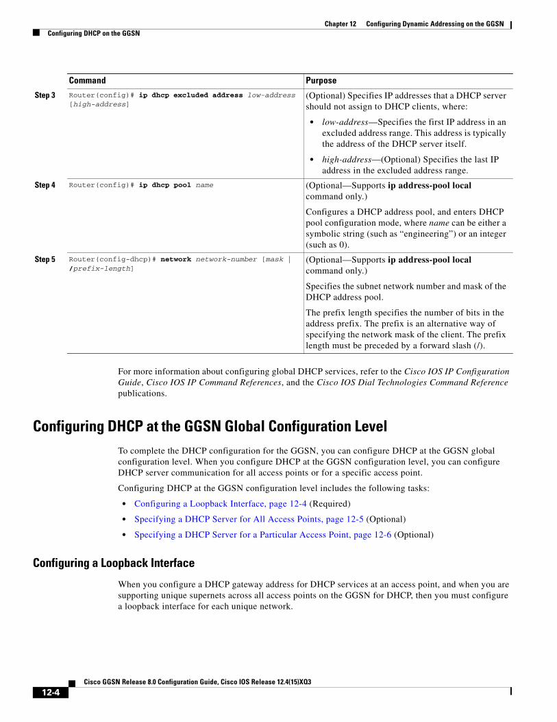
Chapter 12 Configuring Dynamic Addressing on the GGSNConfiguring DHCP on the GGSN
For more information about configuring global DHCP services, refer to the Cisco IOS IP Configuration Guide, Cisco IOS IP Command References, and the Cisco IOS Dial Technologies Command Reference publications.
Configuring DHCP at the GGSN Global Configuration LevelTo complete the DHCP configuration for the GGSN, you can configure DHCP at the GGSN global configuration level. When you configure DHCP at the GGSN configuration level, you can configure DHCP server communication for all access points or for a specific access point.
Configuring DHCP at the GGSN configuration level includes the following tasks:
• Configuring a Loopback Interface, page 12-4 (Required)
• Specifying a DHCP Server for All Access Points, page 12-5 (Optional)
• Specifying a DHCP Server for a Particular Access Point, page 12-6 (Optional)
Configuring a Loopback Interface
When you configure a DHCP gateway address for DHCP services at an access point, and when you are supporting unique supernets across all access points on the GGSN for DHCP, then you must configure a loopback interface for each unique network.
Step 3 Router(config)# ip dhcp excluded address low-address [high-address]
(Optional) Specifies IP addresses that a DHCP server should not assign to DHCP clients, where:
• low-address—Specifies the first IP address in an excluded address range. This address is typically the address of the DHCP server itself.
• high-address—(Optional) Specifies the last IP address in the excluded address range.
Step 4 Router(config)# ip dhcp pool name (Optional—Supports ip address-pool local command only.)
Configures a DHCP address pool, and enters DHCP pool configuration mode, where name can be either a symbolic string (such as “engineering”) or an integer (such as 0).
Step 5 Router(config-dhcp)# network network-number [mask | /prefix-length]
(Optional—Supports ip address-pool local command only.)
Specifies the subnet network number and mask of the DHCP address pool.
The prefix length specifies the number of bits in the address prefix. The prefix is an alternative way of specifying the network mask of the client. The prefix length must be preceded by a forward slash (/).
Command Purpose
12-4Cisco GGSN Release 8.0 Configuration Guide, Cisco IOS Release 12.4(15)XQ3

Chapter 12 Configuring Dynamic Addressing on the GGSNConfiguring DHCP on the GGSN
A loopback interface is a software-only interface that emulates an interface that is always up. It is a virtual interface supported on all platforms. The interface number is the number of the loopback interface that you want to create or configure. There is no limit on the number of loopback interfaces you can create.
To configure a loopback interface on the GGSN, use the following commands, beginning in global configuration mode:
Specifying a DHCP Server for All Access Points
When processing DHCP address allocation, the GGSN software first checks to see whether a DHCP server has been specified at the access-point configuration level. If a server has been specified, the GGSN uses the DHCP server specified at the access point. If no DHCP server is specified at the access-point configuration level, then the GGSN uses the default GGSN DHCP server.
Command Purpose
Step 1 Router(config)# interface loopback interface-number Defines a loopback interface on the GGSN, where interface-number identifies the loopback interface.
Step 2 Router(config-if)# ip address ip-address mask [secondary]
Specifies an IP address for the interface, where:
• ip-address—Specifies the IP address of the interface in dotted decimal format.
• mask—Specifies a subnet mask in dotted decimal format.
• secondary—Specifies that the configured address is a secondary IP address. If this keyword is omitted, the configured address is the primary IP address.
Note The ip-address corresponds to the IP address of the DHCP gateway address at the access point. The mask should be 255.255.255.255 to match the dhcp-gateway-address value exactly.
12-5Cisco GGSN Release 8.0 Configuration Guide, Cisco IOS Release 12.4(15)XQ3

Chapter 12 Configuring Dynamic Addressing on the GGSNConfiguring DHCP on the GGSN
To specify a DHCP server for all GGSN access points, use the following commands, beginning in global configuration mode:
Specifying a DHCP Server for a Particular Access Point
To override the default DHCP server configured for all access points, you can specify a different DHCP server for a particular access point. Or, if you choose not to configure a default GGSN DHCP server, you can specify a DHCP server at each access point.
Command Purpose
Step 1 Router(config)# gprs default ip-address-pool {dhcp-proxy-client | radius-client | disable}
Specifies a dynamic address allocation method using IP address pools for the GGSN, where:
• dhcp-proxy-client—Specifies that the GGSN dynamically acquires IP addresses for a mobile station (MS) from a DHCP server. Use this keyword to enable DHCP services.
• radius-client—Specifies that the GGSN dynamically acquires IP addresses for an MS from a RADIUS server.
• disable—Disables dynamic address allocation by the GGSN.
There is no default option for this command.
Step 2 Router(config)# gprs default dhcp-server {ip-address | name} [{ip-address | name}]
Specifies a primary (and backup) DHCP server from which the GGSN obtains IP address leases for mobile users, where:
• ip-address—Specifies the IP address of a DHCP server. The second (optional) ip-address argument specifies the IP address of a backup DHCP server.
• name—Specifies the host name of a DHCP server. The second (optional) name argument specifies the host name of a backup DHCP server.
12-6Cisco GGSN Release 8.0 Configuration Guide, Cisco IOS Release 12.4(15)XQ3

Chapter 12 Configuring Dynamic Addressing on the GGSNConfiguring DHCP on the GGSN
To specify a DHCP server for a particular access point, use the following commands, beginning in access-point configuration mode:
Command Purpose
Step 1 Router(config-access-point)# ip-address-pool {dhcp-proxy-client | radius-client | local pool-name | disable}
(Optional) Specifies a dynamic address allocation method using IP address pools for the current access point. The available options are:
• dhcp-proxy-client—DHCP server provides the IP address pool.
• radius-client—RADIUS server provides the IP address pool.
• local—Specifies that a local pool provides the IP address. This option requires that a local pool has been configured using the ip local pool global configuration command.
• disable—Turns off dynamic address allocation.
Note If you are using a dynamic address allocation method, then you must configure this command according to the appropriate IP address pool source.
Step 2 Router(config-access-point)# dhcp-server {ip-address} [ip-address] [vrf]
Specifies a primary (and backup) DHCP server that the GGSN uses at a particular access point to obtain IP address leases for mobile users for access to a PDN, where:
• ip-address—Specifies the IP address of a DHCP server. The second (optional) ip-address argument specifies the IP address of a backup DHCP server.
• vrf—DHCP server uses the VPN routing and forwarding (VRF) table that is associated with the APN.
Step 3 Router(config-access-point)# dhcp-gateway-address ip-address
Specifies the subnet in which the DHCP server should return addresses for DHCP requests for MS users entering a particular PDN access point.
Note You must configure a corresponding loopback interface with the same IP address as the DHCP gateway address.
12-7Cisco GGSN Release 8.0 Configuration Guide, Cisco IOS Release 12.4(15)XQ3

Chapter 12 Configuring Dynamic Addressing on the GGSNConfiguring DHCP on the GGSN
Configuring a Local DHCP Server
Note We do not recommend using a local DHCP server on the Cisco 7600 platform.
Although most networks use external DHCP servers, such as that available through the Cisco Network Registrar (CNR), you can also configure internal DHCP services on the GGSN. If you use local DHCP services on the GGSN, then there are a couple of commands that you should configure to improve the internal DHCP response times.
To optimize local DHCP services on the GGSN, use the following commands, beginning in global configuration mode:
Configuration ExampleThe following example shows a VRF configuration for vpn3 (without tunneling) using the ip vrf global configuration command. Because the ip vrf command establishes both VRF and CEF routing tables, notice that ip cef also is configured at the global configuration level to enable CEF switching at all of the interfaces.
The following other configuration elements must also associate the same VRF named vpn3:
• FastEthernet0/0 is configured as the Gi interface using the ip vrf forwarding interface configuration command.
• Access-point 2 implements VRF using the vrf command access-point configuration command.
The DHCP server at access-point 2 also is configured to support VRF. Notice that access-point 1 uses the same DHCP server, but is not supporting the VRF address space. The IP addresses for access-point 1 will apply to the global routing table:
aaa new-model!aaa group server radius abc server 10.2.3.4 server 10.6.7.8!aaa authentication ppp abc group abcaaa authorization network abc group abc aaa accounting network abc start-stop group abc!ip cef!ip vrf vpn3 rd 300:3!interface Loopback1 ip address 10.30.30.30 255.255.255.255!interface Loopback2
Command Purpose
Step 1 Router(config)# ip dhcp ping packets 0 Specifies that the Cisco IOS DHCP Server sends 0 packets to a pool address as part of a ping operation.
Step 2 Router(config)# ip dhcp ping timeout 100 Specifies that the Cisco IOS DHCP Server waits for a ping reply from an address pool for 100 milliseconds.
12-8Cisco GGSN Release 8.0 Configuration Guide, Cisco IOS Release 12.4(15)XQ3

Chapter 12 Configuring Dynamic Addressing on the GGSNConfiguring DHCP on the GGSN
ip vrf forwarding vpn3 ip address 10.27.27.27 255.255.255.255!interface FastEthernet0/0 ip vrf forwarding vpn3 ip address 10.50.0.1 255.255.0.0 duplex half!interface FastEthernet1/0 ip address 10.70.0.1 255.255.0.0 duplex half!interface loopback 1 ip address 10.8.0.1 255.255.255.0!interface Virtual-Template1 ip unnumber loopback 1 encapsulation gtp gprs access-point-list gprs!ip route 10.10.0.1 255.255.255.255 Virtual-Template1ip route vrf vpn3 10.100.0.5 255.255.255.0 fa0/0 10.50.0.2ip route 10.200.0.5 255.255.255.0 fa1/0 10.70.0.2!no ip http server!gprs access-point-list gprs access-point 1 access-point-name gprs.pdn.com ip-address-pool dhcp-proxy-client dhcp-server 10.200.0.5 dhcp-gateway-address 10.30.30.30 network-request-activation exit ! access-point 2 access-point-name gprs.pdn2.com access-mode non-transparent ip-address-pool dhcp-proxy-client dhcp-server 10.100.0.5 10.100.0.6 vrf dhcp-gateway-address 10.27.27.27 aaa-group authentication abc vrf vpn3 exit!gprs default ip-address-pool dhcp-proxy-client!radius-server host 10.2.3.4 auth-port 1645 acct-port 1646 non-standardradius-server host 10.6.7.8 auth-port 1645 acct-port 1646 non-standardradius-server key ggsntel
12-9Cisco GGSN Release 8.0 Configuration Guide, Cisco IOS Release 12.4(15)XQ3

Chapter 12 Configuring Dynamic Addressing on the GGSNConfiguring MS Addressing via Local Pools on the GGSN
Configuring MS Addressing via Local Pools on the GGSNAs the number of PDP contexts increases, allocating IP addresses via locally-configured address pools improves the PDP context activation rate. Whether or not addresses are allocated to MSs using local pools is specified at the access-point configuration level and requires that a local pool or pools of IP address have been configured on the GGSN using the ip local pool configuration command.
Hold Back Timer
The IP local pool hold back timer feature (recycle delay keyword option) enables you to configure a specific amount of time a newy-released IP address is held before being made available for reassignment. This ensures that an IP address recently released when a PDP session was deleted is not re-assigned to another PDP context before the IP-to-user relationship has been deleted from all back-end components of the system. If an IP address is reassgined to a new PDP context immediately, the back-end system could incorrectly associate the new user with the record of the previous user, and therefore associate the charging and service access of the new user to the previous user.
The hold back functionality is provided by the support of a new timestamp field added to the pool element data structure. When a request to allocate a specific address is made, if the address is available for reassignment, the current time is checked agains the timestamp field of the element. If that number is equal to, or exceeds the number of seconds configured for the recycle delay, the address is reassigned.
When a request is made to allocate the first free address from the free queue, the difference between the current timesteamp and the timestamp stored for the element is calculated. If the number is equal to, or exceeds, the configured recycle delay, the address is allocated. If the number is not equal to, or does not exceed the configured recycle delay, the address is not allocated for that request. (The free queue is a first-in first-out [FIFO] queue. Therefore, all other elements will have a great recycle delay than the first element.)
When an address assignment is blocked because an IP address is held for some time, a count of blocked address assignments that is maintained for the local pool is incremented.
Note The hold back timer feature does not support IPv6 local pools.
12-10Cisco GGSN Release 8.0 Configuration Guide, Cisco IOS Release 12.4(15)XQ3

Chapter 12 Configuring Dynamic Addressing on the GGSNConfiguring MS Addressing via Local Pools on the GGSN
To configure a local IP address pool, use the following command in global configuration mode:
To assign a local pool to an access-point, use the following command in access-point configuration mode:
Note Using VRF at the access point, you can configure APNs that use the same IP address pool (overlapping addresses). Fore more information on configuring VPN access via VRF from an access point, see the “VPN Access Using VRF Configuration Task Lists” section on page 8-13.
Command Purpose
Step 1 Router(config)#ip local pool {default | pool-name low-ip-address [high-ip-address]} [recycle delay seconds]
Configures a local pool of IP addresses to be used when a remote peer connects to a point-to-point interface, where:
• default—Default local address pool is used if no other pool is named.
• pool-name—Name of a specific local address pool.
• low-ip-address—Lowest IP address in the pool.
• high-ip-address—(Optional) Highest IP address in the pool. If this value is omitted, only the low-ip-address IP address argument is included in the local pool.
• recycle delay seconds—(Optional) The time, in seconds, addresses should be held before making them available for reassignment.
Command Purpose
Step 1 Router(config-access-point)# ip-address-pool local pool-name
(Optional) Specifies that a local pool provides the IP address.
12-11Cisco GGSN Release 8.0 Configuration Guide, Cisco IOS Release 12.4(15)XQ3

Chapter 12 Configuring Dynamic Addressing on the GGSNConfiguring MS Addressing via RADIUS
To verify the local pool configure, use the show ip local [pool name] command in privileged EXEC mode:
Router#show ip local poolPool Begin End Free In use Blockedpoola 10.8.8.1 10.8.8.5 5 0 0
Router #show ip local pool poolAPool Begin End Free In use Blockedpoola 10.8.8.1 10.8.8.5 5 0 0
Available addresses:10.8.8.1 10.8.8.2 10.8.8.3 10.8.8.4 10.8.8.5
Inuse addresses:None
Held addresses: Time RemainingNone
Configuration ExampleThe following is a configuration example of a local address pool configured at the APN.
!ip local pool local_pool1 128.1.0.1 128.1.255.254!access-point 1access-point-name gprs.pdn.comip-address-pool local local_pool1aggregate 128.1.0.0/16exit
Configuring MS Addressing via RADIUSDynamic IP addressing via a RADIUS server is configured at the access-point configuration level using the ip-address-pool access-point configuration command.
For more information about the ip-address-pool access-point configuration command, see “Configuring Additional Real Access Point Options” section on page 8-20. For more information about configuring RADIUS, see the Cisco IOS Security Configuration Guide.
Configuring IP Overlapping Address PoolsThe IP Overlapping Address Pools feature improves flexibility in assigning IP addresses dynamically. This feature allows you to configure overlapping IP address pool groups to create different address spaces and concurrently use the same IP addresses in different address spaces.
12-12Cisco GGSN Release 8.0 Configuration Guide, Cisco IOS Release 12.4(15)XQ3

Chapter 12 Configuring Dynamic Addressing on the GGSNConfiguring IP Overlapping Address Pools
IP Overlapping Address Pools gives greater flexibility in assigning IP addresses dynamically. It allows you to configure overlapping IP address pool groups to create different address spaces and concurrently use the same IP addresses in different address spaces.
With Cisco IOS Release 12.3(2)XB and later, the GGSN supports the concept of an IP address group to support multiple IP address spaces and still allow the verification of nonoverlapping IP address pools within a pool group. Pool names must be unique within the GGSN. The pool name carries an implicit group identifier because that pool name can be associated only with one group. Pools without an explicit group name are considered members of the base system group and are processed in the same manner as the original IP pool implementation.
Existing configurations are not affected by the new pool feature. The “group” concept is an extension of the existing ip local pool command. Processing of pools that are not specified as a member of a group is unchanged from the existing implementation.
To configure a local IP address pool group and verify that it exists, use the following commands in global configuration mode:
Configuration ExamplesThe following are configuration examples for configuring IP overlapping address pools.
• Defining Local Address Pooling as the Global Default, page 12-14
• Configuring Multiple Ranges of IP Addresses into One Pool Example, page 12-14
• Configuring IP Overlapping Address Pools on a GGSN on the Cisco 7600 Platform with Supervisor II / MSFC2 Example, page 12-14
Command Purpose
Step 1 Router(config)#ip local pool {default | pool-name low-ip-address [high-ip-address]}
Example: GGSN(config)# ip local pool testpool 10.2.2.1 10.2.2.10 group testgroup cache-size 10000
Configures a local pool of IP addresses to be used when a remote peer connects to a point-to-point interface, where:
• default—Defaults local address pool that is used if no other pool is named.
• pool-name—Name of a specific local address pool.
• low-ip-address—Lowest IP address in the pool.
• high-ip-address—(Optional) Highest IP address in the pool. If this value is omitted, only the low-ip-address IP address argument is included in the local pool.
Step 2 Router(config)# show ip local pool [poolname | [group group-name]]
Example: GGSN(config)# show ip local pool group testgroup testpool
Displays statistics for any defined IP address pools.
12-13Cisco GGSN Release 8.0 Configuration Guide, Cisco IOS Release 12.4(15)XQ3

Chapter 12 Configuring Dynamic Addressing on the GGSNConfiguring IP Overlapping Address Pools
Defining Local Address Pooling as the Global Default
The following example shows how to configure local pooling as the global default mechanism:
ip address-pool local ip local pool default 192.169.15.15 192.68.15.16
Configuring Multiple Ranges of IP Addresses into One Pool Example
The following example shows how to configure two ranges of IP addresses for one IP address pool:
ip local pool default 192.169.10.10 192.169.10.20 ip local pool default 192.169.50.25 192.169.50.50
Configuring IP Overlapping Address Pools on a GGSN on the Cisco 7600 Platform with Supervisor II / MSFC2 Example
The following example shows how to configure IP overlapping address pools on the Cisco 7600 platform
The following examples also show a partial configuration for two VPNs (vpn1 and vpn2) and their associated GRE tunnel configurations (Tunnel1 and Tunnel2).
On the GGSN:
service gprs ggsn!hostname 7600-7-2!ip cef!ip vrf vpn1 description GRE Tunnel 1 rd 100:1!ip vrf vpn2 description GRE Tunnel 3 rd 101:1!interface Loopback1 ip address 150.1.1.72 255.255.0.0!interface Loopback100 description GPRS GTP V-TEMPLATE IP ADDRESS ip address 9.9.9.72 255.255.255.0!interface Tunnel1 description VRF-GRE to PDN 7500(13) Fa0/1 ip vrf forwarding vpn1 ip address 50.50.52.72 255.255.255.0 tunnel source 150.1.1.72 tunnel destination 165.2.1.13!interface Tunnel2 description VRF-GRE to PDN PDN x(12) Fa3/0 ip vrf forwarding vpn2 ip address 80.80.82.72 255.255.255.0 tunnel source 150.1.1.72 tunnel destination 167.2.1.12!interface GigabitEthernet0/0.1 description Gi encapsulation dot1Q 100
12-14Cisco GGSN Release 8.0 Configuration Guide, Cisco IOS Release 12.4(15)XQ3

Chapter 12 Configuring Dynamic Addressing on the GGSNConfiguring IP Overlapping Address Pools
ip address 10.1.2.72 255.255.255.0!interface Virtual-Template1 description GTP v-access ip unnumbered Loopback100 encapsulation gtp gprs access-point-list gprs!router ospf 10 network 10.1.2.0 0.0.0.255 area 10 network 150.1.0.0 0.0.255.255 area 10!ip local pool vpn1_pool 100.2.0.1 100.2.255.255 group vpn1ip local pool vpn2_pool 100.2.0.1 100.2.255.255 group vpn2ip route vrf vpn1 0.0.0.0 255.255.255.0 Tunnel1ip route vrf vpn2 0.0.0.0 255.255.255.0 Tunnel2
gprs access-point-list gprs access-point 1 access-point-name apn.vrf1.com access-mode non-transparent aaa-group authentication ipdbfms ip-address-pool local vpn1_pool vrf vpn1 ! access-point 2 access-point-name apn.vrf2.com access-mode non-transparent aaa-group authentication ipdbfms ip-address-pool local vpn2_pool vrf vpn2 !
Related configuration on the Supervisor / MSFC2:
interface FastEthernet9/5 no ip address switchport switchport access vlan 167 no cdp enable!interface FastEthernet9/10 no ip address switchport switchport access vlan 165 no cdp enable!interface Vlan165 ip address 165.1.1.1 255.255.0.0!interface Vlan167 ip address 167.1.1.1 255.255.0.0!! provides route to tunnel endpoints on GGSNsrouter ospf 10 network 10.1.2.0 0.0.0.255 area 10 !! routes to tunnel endpoints on PDN!ip route 165.2.0.0 255.255.0.0 165.1.1.13ip route 167.2.0.0 255.255.0.0 167.1.1.12
12-15Cisco GGSN Release 8.0 Configuration Guide, Cisco IOS Release 12.4(15)XQ3

Chapter 12 Configuring Dynamic Addressing on the GGSNConfiguring the NBNS and DNS Address for an APN
Configuring the NBNS and DNS Address for an APNYou can configure a primary and secondary NetBIOS Name Service (NBNS) and domain name system (DNS) under an APN. This feature is benefits address allocation schemes where there is no mechanism to obtain these address. Also, for a RADIUS-based allocation scheme, it prevents the operator from having to configure a NBNS and DNS under each user profile.
The NBNS and DNS addresses can come from three possible sources: DHCP server, RADIUS server, or local APN configuration. The criterium for selecting the addresses depends on the IP address allocation scheme configured under the APN. Depending on the configuration, the criterium for selecting the DNS and NBNS addresses is as follows:
1. DHCP-based IP address allocation scheme (local and external)—NBNS address returned from the DHCP server is sent to the MS. If the DHCP server does not return an NBNS address, the local APN configuration is used.
2. RADIUS-based IP address allocation scheme—NBNS address returned from the RADIUS server (in Access-Accept responses) is used. If the RADIUS server does not return an NBNS address, the local APN configuration is used.
3. Local IP Address Pool-based IP address allocation scheme—Local APN configuration is used.
4. Static IP Addresses—Local APN configuration is used.
Note The GGSN sends NBNS and DNS addresses in the create PDP response only if the MS is requesting the DNS address in the PCO IE.
To specify a primary (and backup) NBNS to be sent in create PDP responses at the access point, use the nbns primary access-point configuration command. To remove the NBNS from the access-point configuration, use the no form of this command
nbns primary ip-address [secondary ip-address]
To specify a primary (and backup) DNS to be sent in create PDP responses at the access point, use the dns primary access-point configuration command. To remove the DNS from the access-point configuration, use the no form of this command
dns primary ip-address [secondary ip-address]
12-16Cisco GGSN Release 8.0 Configuration Guide, Cisco IOS Release 12.4(15)XQ3

Cisco GGSN Release 8.0
C H A P T E R13
Configuring Load Balancing on the GGSNThis chapter describes how to configure a gateway GPRS support node (GGSN) to support load balancing functions using the Cisco IOS software Server Load Balancing (SLB) feature. GTP load balancing provides increased reliability and availability when you are using multiple Cisco GGSNs or non-Cisco GGSNs in your GPRS/UMTS network.
For a complete description of the GGSN commands in this chapter, refer to the Cisco GGSN Command Reference for the Cisco GGSN release you are using. For a complete description of the other Cisco IOS SLB commands in this chapter, refer to the IOS Server Load Balancing feature module.
To locate documentation of other commands that appear in this chapter, use the command reference master index or search online.
This chapter includes the following sections:
• Overview of GTP Load Balancing, page 13-1
• Configuring GTP Load Balancing, page 13-7
• Monitoring and Maintaining the Cisco IOS SLB Feature, page 13-24
• Configuration Examples, page 13-26
Overview of GTP Load BalancingThis section provides an overview of the Cisco IOS SLB feature and GTP load balancing support on the GGSN. It includes the following sections:
• Overview of Cisco IOS SLB, page 13-1
• Overview of GTP Load Balancing, page 13-2
• GTP SLB Restrictions, page 13-7
Overview of Cisco IOS SLBThe Cisco SLB feature is an IOS-based solution that provides IP server load balancing. Using the Cisco IOS SLB feature, you can define a virtual server that represents a group of real servers in a cluster of network servers known as a server farm. In this environment, the clients connect to the IP address of the virtual server. When a client initiates a connection to the virtual server, the Cisco IOS SLB feature chooses a real server for the connection, based on a configured load-balancing algorithm.
The Cisco IOS SLB feature also provides firewall load balancing, which balances flows across a group of firewalls called a firewall farm.
13-1Configuration Guide, Cisco IOS Release 12.4(15)XQ3

Chapter 13 Configuring Load Balancing on the GGSNOverview of GTP Load Balancing
Figure 13-1 presents a logical view of a simple Cisco IOS SLB network.
Figure 13-1 Logical View of IOS SLB
Overview of GTP Load BalancingCisco IOS SLB provides GGSN GTP load balancing and increased reliability and availability for the GGSN. GGSN GTP load balancing supports a subset of the overall server load-balancing functions that are available in the Cisco IOS SLB feature. Therefore, the full scope of Cisco IOS SLB functions is not applicable to the general packet radio service/Universal Mobile Telecommunication System (GPRS/UMTS) environment. For more information about unsupported functions, see the “GTP SLB Restrictions” section on page 13-7.
When configuring GTP load balancing, a pool of GGSNs is configured as a server farm in Cisco IOS SLB. These are the GGSNs across which you want to load-balance GTP sessions. A virtual server instance is configured in Cisco IOS SLB to load balance GTP sessions across the GGSN farm. This virtual server is associated with the server farm that you configured in Cisco IOS SLB.
When configuring GTP load balancing, note the following:
• GTP load balancing is supported by using the Cisco IOS SLB feature on the supervisor engine.
• The IOS SLB on the supervisor engine processes only the create PDP context requests sent to the GGSN virtual IP address. When a create PDP context request is received, a real GGSN is selected based on the load at that time. Once the PDP context has been established, all subsequent transactions corresponding to the PDP contexts occurs directly between that GGSN and corresponding SGSN, bypassing the Cisco IOS SLB on the supervisor engine.
Client Client
ClientClient
IOS SLBdevice
Realserver
Realserver
Virtual server
Realserver
4577
0
13-2Cisco GGSN Release 8.0 Configuration Guide, Cisco IOS Release 12.4(15)XQ3

Chapter 13 Configuring Load Balancing on the GGSNOverview of GTP Load Balancing
• Additionally:
– Multiple virtual servers are supported
– Load-balanced real servers can be internal or external to the Cisco 7600 chassis
– Each virtual server must have one unique public IP address that is reachable from the SGSNs
– Each virtual server can correspond to one or more APNs.
– The DNS server used by the SGSNs to resolve the APNs to a GGSN IP address should use the GGSN virtual IP address.
Supported GTP Load Balancing Types
The Cisco IOS SLB supports two types of GTP load balancing:
• GTP Load Balancing Without GTP Cause Code Inspection, page 13-3
• GTP Load Balancing With GTP Cause Code Inspection, page 13-3
GTP Load Balancing Without GTP Cause Code Inspection
GTP load balancing without GTP cause code inspection enabled is recommended for Cisco GGSNs. It has the following characteristics:
• Can operate in dispatched mode or in directed server Network Address Translation (NAT) mode, but not in directed client NAT mode. In dispatched mode, the GGSNs must be Layer 2–adjacent to the Cisco IOS SLB device.
• Does not support stateful backup.
• Delivers tunnel creation messages destined to the virtual GGSN IP address to one of the real GGSNs, using the weighted round-robin load-balancing algorithm. See the “Weighted Round-Robin” section on page 13-4 for more information about this algorithm.
• Requires Dynamic Feedback Protocol (DFP) to account for GTPv1 secondary PDP contexts.
GTP Load Balancing With GTP Cause Code Inspection
GTP load balancing with GTP cause code inspection enabled allows Cisco IOS SLB to monitor all PDP context signaling flows to and from server farms. This enables Cisco IOS SLB to monitor GTP failure cause codes, detecting system-level problems in both Cisco and non-Cisco GGSNs.
Table 13-1 lists the Create PDP Context response cause codes and the corresponding actions taken by Cisco IOS SLB.
Table 13-1 PDP Create Response Cause Codes and Corresponding Cisco IOS SLB Actions
Cause Code Cisco IOS SLB Action
Request Accepted Establish session
No Resource Available Fail current real, reassign session, drop the response
All dynamic addresses are occupied Fail current real, reassign session, drop the response
No memory is available Fail current real, reassign session, drop the response
System Failure Fail current real, reassign session, drop the response
Missing or Unknown APN Forward the response
Unknown PDP Address or PDP type Forward the response
13-3Cisco GGSN Release 8.0 Configuration Guide, Cisco IOS Release 12.4(15)XQ3

Chapter 13 Configuring Load Balancing on the GGSNOverview of GTP Load Balancing
GTP load balancing with GTP cause code inspection enabled has the following characteristics:
• Must operate in directed server NAT mode.
• Assigns PDP context creates from a specific International Mobile Subscriber ID (IMSI) to the same GGSN, or, if GTP APN-aware load balancing is configured, to the same server farm.
• Supports stateful backup.
• Tracks the number of open PDP contexts for each GGSN or APN, which enables server farms to use the weighted least connections (leastconns) algorithm for GTP load balancing. See the “Weighted Least Connections” section on page 13-5 for more information about this algorithm.
• Enables Cisco IOS SLB to deny access to a virtual GGSN if the carrier code of the requesting IMSI does not match a specified value.
• Enables Cisco IOS SLB to support secondary IPDP contexts, even without DFP.
Cisco IOS SLB Algorithms Supported for GTP Load Balancing
The following two Cisco IOS SLB algorithms are supported for GTP load balancing:
• Weighted Round-Robin, page 13-4
• Weighted Least Connections, page 13-5
Weighted Round-Robin
The weighted round- robin algorithm specifies that the real server used for a new connection to the virtual server is chosen from the server farm in a circular fashion. Each real server is assigned a weight, n, that represents its capacity to handle connections, as compared to the other real servers associated with the virtual server. That is, new connections are assigned to a given real server n times before the next real server in the server farm is chosen.
For example, assume a server farm made up of three real servers: ServerA with n = 3, ServerB with n = 1, and ServerC with n = 2. The first three connections to the virtual server are assigned to ServerA, the fourth connection to ServerB, and the fifth and sixth connections to ServerC.
User Authentication Failed Forward the response
Semantic error in TFT operation Forward the response
Syntactic error in TFT operation Forward the response
Semantic error in packet filter Forward the response
Syntactic error in packet filter Forward the response
Mandatory IE incorrect Forward the response
Mandatory IE missing Forward the response
Optional IE incorrect Forward the response
Invalid message format Forward the response
Version not supported Forward the response
PDP context without TFT already activated
Fail current real, reassign session, drop the response
Table 13-1 PDP Create Response Cause Codes and Corresponding Cisco IOS SLB Actions
Cause Code Cisco IOS SLB Action
13-4Cisco GGSN Release 8.0 Configuration Guide, Cisco IOS Release 12.4(15)XQ3

Chapter 13 Configuring Load Balancing on the GGSNOverview of GTP Load Balancing
Note Assigning a weight of n = 1 to all of the servers in the server farm configures the Cisco IOS SLB device to use a simple round-robin algorithm. GTP load balancing without GTP cause code inspection enabled requires the weighted round-robin algorithm. A server farm that uses weighted least connections can be bound to a virtual server that provides GTP load balancing without GTP cause code inspection enabled, but you cannot place that virtual server INSERVICE. If you try to do so, Cisco IOS SLB issues an error message.
Weighted Least Connections
When GTP cause code inspection is enabled, GTP load balancing supports the Cisco IOS SLB weighted least connections algorithm.
The weighted least connections algorithm specifies that the next real server chosen from a server farm for a new connection to the virtual server is the server with the fewest active connections. Each real server is assigned a weight for this algorithm, also. When weights are assigned, the server with the fewest connections is determined on the basis of the number of active connections on each server and the relative capacity of each server. The capacity of a given real server is calculated as the assigned weight of that server divided by the sum of the assigned weights of all the real servers associated with that virtual server, or n1/(n1+n2+n3...).
For example, assume a server farm made up of three real servers: ServerA with n = 3, ServerB with n = 1, and ServerC with n = 2. ServerA would have a calculated capacity of 3/(3+1+2), or half of all active connections on the virtual server, ServerB would have a calculated capacity of one-sixth of all active connections, and ServerC one-third of all active connections. At any point in time, the next connection to the virtual server would be assigned to the real server whose number of active connections is farthest below its calculated capacity.
Note Assigning a weight of n = 1 to all of the servers in the server farm configures the Cisco IOS SLB device to use a simple least-connection algorithm. GTP load balancing without GTP cause code inspection enabled does not support the weighted least connections algorithm. GTP load balancing with GTP cause code inspection does support the weighted least connections algorithm.
Dynamic Feedback Protocol for Cisco IOS SLB
In GTP load balancing, Cisco IOS SLB detects when a PDP context is established, but it does not detect when PDP contexts are cleared, and therefore it cannot determine the number of open PDP contexts for each GGSN. Use the Cisco IOS SLB DFP to calculate GPRS/UMTS load-balancing weights dynamically.
With Cisco IOS SLB DFP support, a DFP manager in a load-balancing environment can initiate a TCP connection with a DFP agent. Thereafter, the DFP agent collects status information from one or more real host servers, converts the information to relative weights, and reports the weights to the DFP manager. The DFP manager factors in the weights when load balancing the real servers. In addition to reporting at user-defined intervals, the DFP agent sends an early report if there is a sudden change in a real server’s status.
13-5Cisco GGSN Release 8.0 Configuration Guide, Cisco IOS Release 12.4(15)XQ3

Chapter 13 Configuring Load Balancing on the GGSNOverview of GTP Load Balancing
The weights calculated by DFP override the static weights you define using the weight (server farm) command. If DFP is removed from the network, Cisco IOS SLB reverts to the static weights.
You can define Cisco IOS SLB as a DFP manager, as a DFP agent for another DFP manager (such as DistributedDirector), or as both at the same time. In such a configuration, Cisco IOS SLB sends periodic reports to DistributedDirector, which uses the information to choose the best server farm for each new connection request. Cisco IOS SLB then uses the same information to choose the best real server within the chosen server farm.
DFP also supports the use of multiple DFP agents from different client subsystems (such as Cisco IOS SLB and GPRS/UMTS) at the same time.
In GTP load balancing, you can define Cisco IOS SLB as a DFP manager and define a DFP agent on each GGSN in the server farm, and the DFP agent can report the weights of the GGSNs. The DFP agents calculate the weight of each GGSN, based on CPU utilization, processor memory, and the maximum number of PDP contexts that can be activated for each GGSN.
The weight for each GGSN is based primarily on the ratio of existing PDP contexts on the GGSN and the maximum number of allowed PDP contexts.
CPU and memory utilization become part of the weight calculation only after the utilization exceeds 85%. Because the maximum number of allowed PDP contexts is considered to be the GGSNs maximum load, you should carefully consider the value that you configure in the gprs maximum-pdp-context-allowed command, which defaults to 10,000 PDP contexts.
GTP IMSI Sticky Database Support
Cisco IOS SLB can select a GGSN, or APN if GTP APN-aware load balancing is configured, for a given International Mobile Subscriber ID (IMSI), and forward all subsequent Packet Data Protocol (PDP) create requests from the same IMSI to the selected GGSN or APN.
To enable this feature, Cisco IOS SLB uses a GTP IMSI sticky database, which maps each IMSI to its corresponding real server, in addition to its session database.
The Cisco IOS SLB creates a sticky database object when it processes the first create PDP context request for a given IMSI. The Cisco IOS SLB removes the sticky object when it receives a notification to do so from the real server, or as a result of inactivity. When the last PDP belonging to an IMSI is deleted, the GGSN notifies Cisco IOS SLB to remove the sticky object.
Sticky Database Support and GTP APN-Aware Load Balancing
The sticky IMSI feature prevents sessions from the same user for the same APN being assigned to different GGSNs. With server farm selection based on APN (APN-aware load balancing), the sticky IMSI feature ensures that a sticky entry is for the same server farm based on the APN before the IMSI can be issued. If a new create PDP context request is for a different APN, which causes GTP SLB to select a different server farm than the one for which the sticky entry was created, the server farm is respected over the real because if the real belongs to a different server farm, the serverfarm might not support the APN.
13-6Cisco GGSN Release 8.0 Configuration Guide, Cisco IOS Release 12.4(15)XQ3

Chapter 13 Configuring Load Balancing on the GGSNConfiguring GTP Load Balancing
GTP APN-Aware Load Balancing
With Cisco IOS software release 12.2(18) SRB and later on the supervisor engine, GTP APN-aware load balancing can be configured.
Using the GTP APN-aware feature, a set of APNs can be mapped to a server farm in the Cisco IOS SLB. Multiple server farms can be created, each supporting a different set of APNs. Create PDP context requests are balanced across APNs.
For information on configuring GTP APN-aware load balancing, see the “Configuring GTP APN-Aware Load Balancing” section on page 13-15.
GTP SLB Restrictions The following restrictions apply when configuring GTP load balancing:
• For GTP load balancing without GTP cause code inspection enabled:
– Operates in either dispatched mode or directed server NAT mode only
– Cannot load balance network-initiated PDP context requests
– Does not support the following Cisco IOS SLB functions:
- Bind IDs
- Client-assigned load balancing
- Slow Start
- Stateful backup (not supported on the Cisco 7600 platform)
- Weighted least connections load-balancing algorithm
• For GTP load balancing with GTP cause code inspection enabled:
– Operates in directed server NAT mode only
– Cannot load-balance network-initiated PDP context requests
– Requires either the SGSN or the GGSN to echo its peer
– Inbound and outbound traffic should be routed via Cisco IOS SLB
– Does not support the following Cisco IOS SLB functions:
- Bind IDs
- Client-assigned load balancing
- Slow Start
- Sticky connections
Configuring GTP Load BalancingThis section includes the following topics:
• GTP Load Balancing Configuration Task List, page 13-8
• Configuration Guidelines, page 13-8
13-7Cisco GGSN Release 8.0 Configuration Guide, Cisco IOS Release 12.4(15)XQ3

Chapter 13 Configuring Load Balancing on the GGSNConfiguring GTP Load Balancing
GTP Load Balancing Configuration Task ListThis section lists the tasks used to configure GTP load balancing. Detailed configuration information is contained in the referenced sections of this document or other documents. Required and optional tasks are indicated.
1. On the Cisco IOS SLB, complete the following tasks:
a. Configuring a Server Farm and Real Server, page 13-9 (Required)
b. Configuring a Virtual Server, page 13-11 (Required)
c. Configuring a GSN Idle Timer, page 13-14 (Optional if GTP cause code inspection is enabled)
d. Configuring DFP Support, page 13-14 (Optional, but recommended)
e. Configuring GTP APN-Aware Load Balancing, page 13-15 (Optional)
2. On the GGSN, complete the following tasks:
a. Configuring a Loopback Interface for GTP SLB, page 13-19 (Required)
b. Configuring DFP Support on the GGSN, page 13-20 (Optional, but recommended)
c. Configuring Messaging from the GGSN to the Cisco IOS SLB, page 13-21 (Optional)
3. Routing each GGSN to each associated serving GPRS support node (SGSN) (Required)
The route can be static or dynamic but the GGSN needs to be able to reach the SGSN. For more information, see the “Configuring a Route to the SGSN” section on page 8-4.
4. On the SGSN, route each SGSN to the virtual templates on each associated GGSN, and to the GGSN load-balancing virtual server (Required)
Configuration GuidelinesWhen configuring the network shared by Cisco IOS SLB and the GGSNs, keep the following considerations in mind:
• Specify static routes (using ip route commands) and real server IP addresses (using real commands) so that the Layer 2 information is correct and unambiguous.
• Configure the static route from the SGSN to the virtual server.
• Choose subnets carefully, using one of the following methods:
– Do not overlap virtual template address subnets.
– Specify next-hop addresses to real servers, not to interfaces on those servers.
• Cisco IOS SLB supports two types of GTP load balancing:
– GTP Load Balancing Without GTP Cause Code Inspection, page 13-3
– GTP Load Balancing With GTP Cause Code Inspection, page 13-3
• Cisco IOS SLB supports both GTP v0 and GTP v1. Support for GTP enables Cisco IOS SLB to become “GTP aware,” extending Cisco IOS SLB’s knowledge into Layer 5.
13-8Cisco GGSN Release 8.0 Configuration Guide, Cisco IOS Release 12.4(15)XQ3

Chapter 13 Configuring Load Balancing on the GGSNConfiguring GTP Load Balancing
• On the Cisco 7600 platform, the following apply:
– Multiple GTP virtual servers are supported.
– Load balanced real servers can be internal or external to the Cisco 7600 chassis.
– Each GTP virtual server must have one unique public IP address that is reachable from the SGSNs.
– Each virtual server can correspond to one or more APNs.
– The DNS server used by the SGSNs to resolve the APNs to a GGSN IP address should use the GTP virtual IP address.
• When configuring GTP APN-aware load balancing, note the following:
– Cisco IOS software release 12.2(18) SRB and later is required on the supervisor engine and Cisco GGSN Release 7.0, Cisco IOS Release 12.4(9)XG and later is required on the GGSN.
– GTP load balancing with GTP cause code inspection enabled is not supported.
– For a given IOS SLB GTP map, you can configure up to 100 apn commands, however, because APN maps can impact performance, we recommend that you do not configure more than 10 APN maps per vserver.
– The primary and backup virtual servers should have the same mapping rules.
– The same real cannot be configured in multiple server farms.
Configuring the Cisco IOS SLB for GTP Load BalancingTo configure GTP load balancing, you must complete the following tasks on the Cisco IOS SLB:
• Configuring a Server Farm and Real Server, page 13-9 (Required)
• Configuring a Virtual Server, page 13-11 (Required)
• Configuring a GSN Idle Timer, page 13-14 (Optional)
• Configuring DFP Support, page 13-14 (Optional, but recommended)
• Configuring GTP APN-Aware Load Balancing, page 13-15 (Optional)
• Verifying the Cisco IOS SLB Configuration, page 13-18 (Optional)
Configuring a Server Farm and Real Server
When you configure the server farm and real server on the Cisco IOS SLB for GTP load balancing, use the following guidelines to ensure proper configuration:
• If GTP cause code inspection is not enabled, accept the default setting (the weighted round-robin algorithm) for the predictor command.
If GTP cause code inspection is enabled, you can specify either the weighted round-robin algorithm (roundrobin) or the weighted least connections (leastconns) algorithm.
• Specify the IP addresses (virtual template addresses, for Cisco GGSNs) of the real servers performing the GGSN function, using the real command.
• Specify a reassign threshold less than the SGSN’s N3-REQUESTS counter value by using the reassign command.
13-9Cisco GGSN Release 8.0 Configuration Guide, Cisco IOS Release 12.4(15)XQ3

Chapter 13 Configuring Load Balancing on the GGSNConfiguring GTP Load Balancing
To configure a Cisco IOS SLB server farm, use the following commands, beginning in global configuration mode:
Command Purpose
Step 1 Router-SLB(config)# ip slb serverfarm serverfarm-nameRouter(config-slb-sfarm)#
Adds a server farm definition to the Cisco IOS SLB configuration, and enters server farm configuration mode.
Step 2 Router-SLB(config-slb-sfarm)# predictor [roundrobin | leastconns]
Specifies the algorithm to be used to determine how a real server is selected.
Note In GTP load balancing without GTP cause code inspection enabled, you must accept the default setting (the weighted round-robin algorithm).
See the following sections for more details about each algorithm:
• Weighted Round-Robin, page 13-4
• Weighted Least Connections, page 13-5
Step 3 Router-SLB(config-slb-sfarm)# nat server (Required if GTP cause code inspection is enabled; optional for GTP load balancing without cause code inspection enabled) Configures NAT server address translation mode on the server farm.
Step 4 Router-SLB(config-slb-sfarm)# real ip-address [port] Identifies a real GGSN as a member of a server farm, using the IP address of the GGSN’s virtual template interface, and enters real server configuration mode.
Step 5 Router-SLB(config-slb-real)# faildetect numconns number-conns [numclients number-clients]
(Optional) Specifies the number of consecutive connection failures and, optionally, the number of unique client connection failures, that constitute failure of the real server.
Step 6 Router-SLB(config-slb-real)# maxconns number-conns (Optional) Specifies the maximum number of active connections allowed on the real server at one time.
Note In GTP load balancing without cause code inspection enabled, the impact of this command is minimal because a session will last no longer than the duration specified with the ip gtp request command.
Step 7 Router-SLB(config-slb-real)# reassign threshold (Optional) Specifies the threshold of consecutive unacknowledged synchronizations or Create PDP Context requests that, if exceeded, results in an attempted connection to a different real server.
Step 8 Router-SLB(config-slb-real)# retry retry-value (Optional) Specifies the interval, in seconds, to wait between the detection of a server failure and the next attempt to connect to the failed server.
13-10Cisco GGSN Release 8.0 Configuration Guide, Cisco IOS Release 12.4(15)XQ3

Chapter 13 Configuring Load Balancing on the GGSNConfiguring GTP Load Balancing
Configuring a Virtual Server
When you configure the virtual server on the Cisco IOS SLB for GTP load balancing, use the following guidelines to ensure proper configuration:
• Configure a static route from the SGSN to the virtual server.
• Specify a virtual GGSN IP address as the virtual server, and use the udp keyword option.
• To load-balance GTP v1 sessions, specify port number 2123, if the GGSNs and SGSNs are in compliance with the ETSI standard, or specify port number 0 or any to configure an all-port virtual server (that is, a virtual server that accepts flows destined for all ports).
• To load-balance GTP v0 sessions, specify port number 3386, if the GGSNs and SGSNs are in compliance with the European Telecommunications Standards Institute (ETSI) standard, or specify port number 0 or any to configure an all-port virtual server.
• To enable GTP load balancing without GTP cause code inspection, specify the service gtp keyword option.
• To enable GTP load balancing with GTP cause code inspection, specify the service gtp-inspect keyword option.
In GTP load balancing without GTP cause code inspection enabled, when you configure the GTP idle timer using the idle command, specify a GTP idle timer greater than the longest possible interval between PDP context requests on the SGSN.
Step 9 Router-SLB(config-slb-real)# weight weighting-value (Optional) Specifies the real server’s workload capacity relative to other servers in the server farm.
Note If you use DFP, the static weights you define using the weight (server farm) command are overridden by the weights calculated by DFP. If DFP is removed from the network, Cisco IOS SLB reverts to the static weights.
Step 10 Router-SLB(config-slb-real)# inservice Enables the real server for use by Cisco IOS SLB.
Command Purpose
13-11Cisco GGSN Release 8.0 Configuration Guide, Cisco IOS Release 12.4(15)XQ3

Chapter 13 Configuring Load Balancing on the GGSNConfiguring GTP Load Balancing
To configure an Cisco IOS SLB virtual server, use the following commands, beginning in global configuration mode:
Command Purpose
Step 1 Router-SLB(config)# ip slb vserver virtual_server-name
Identifies a virtual server, and enters virtual server configuration mode.
Step 2 Router-SLB(config-slb-vserver)# virtual ip-addr [netmask [group]] {esp | gre | protocol}
or
Router(config-slb-vserver)# virtual ip-addr [netmask [group]] {tcp | udp} [port | any] [service service]
Specifies the virtual server IP address, type of connection, and optional TCP or UDP port number, Internet Key Exchange (IKE) Internet Security Association and Key Management Protocol (ISAKMP) or Wireless Session Protocol (WSP) setting, and service coupling.
Note For GTP load balancing:
– Specify a virtual GGSN IP address as the virtual server, and specify the udp keyword option.
– To load-balance GTP v1 sessions, specify port number 2123, if the GGSNs and SGSNs are in compliance with the ETSI standard, or specify port number 0 or any to configure an all-port virtual server (that is, a virtual server that accepts flows destined for all ports).
– To load-balance GTP v0 sessions, specify port number 3386, if the GGSNs and SGSNs are in compliance with the ETSI standard, or specify port number 0 or any to configure an all-port virtual server.
– To enable GTP load balancing without GTP cause code inspection, specify the service gtp keyword option.
– To enable GTP load balancing with GTP cause code inspection, specify the service gtp-inspect keyword option.
13-12Cisco GGSN Release 8.0 Configuration Guide, Cisco IOS Release 12.4(15)XQ3

Chapter 13 Configuring Load Balancing on the GGSNConfiguring GTP Load Balancing
Step 3 Router-SLB(config-slb-vserver)# serverfarm primary-farm [backup backup-farm [sticky]] [map map-id priority priority]
Associates a real server farm with a virtual server.
• backup—(Optional) Configures a backup server farm
• backup backup-farm [sticky]—(Optional) Configures a backup server farm and optionally specifies that sticky connections are to be used in the backup server farm.
• map map-id priority priority—(Optional) Associates an IOS SLB protocol map to a server farm for GTP APN-aware load balancing and defines the priority for that map. Maps are searched based on priority. The lower the number, the higher the priority.
Note Multiple instances of the serverfarm command are allowed if configured with the map keyword option. The default server farm (without the map keyword option) is limited to a single instance.
Note To change map configurations the virtual server must be taken out of service.
Note The NAT modes on the primary and backup server farms for each map must match.
Step 4 Router-SLB(config-slb-vserver)# idle [gtp request] duration
(Optional) Specifies the minimum amount of time that Cisco IOS SLB maintains connection context in the absence of packet activity.
The idle command specified without the gtp request keyword option controls the GTP idle timer for GTP load balancing without cause code inspection enable. The idle gtp request command controls the GTP idle timer for both GTP load balancing without cause code inspection enabled and for GTP load balancing with cause code inspection enabled. The idle gtp request is the recommended configuration.
Note In GTP load balancing without GTP cause code inspection enabled, specify a GTP idle timer greater than the longest possible interval between PDP context requests on the SGSN.
Step 5 Router-SLB(config-slb-vserver)# inservice Enables the virtual server for use by Cisco IOS SLB.
Command Purpose
13-13Cisco GGSN Release 8.0 Configuration Guide, Cisco IOS Release 12.4(15)XQ3

Chapter 13 Configuring Load Balancing on the GGSNConfiguring GTP Load Balancing
Configuring a GSN Idle Timer
When GTP cause code inspection is enabled, you can configure the amount of time that the Cisco IOS SLB will maintain sessions to and from and idle GGSN or SGSN.
To configure a GSN idle timer, enter the following command in global configuration mode on the Cisco IOS SLB:
Configuring DFP Support
You can define Cisco IOS SLB as a DFP manager, as a DFP agent for another DFP manager (such as DistributedDirector), or as both at the same time. Depending on your network configuration, you might enter the commands for configuring Cisco IOS SLB as a DFP manager and the commands for configuring Cisco IOS SLB as a DFP agent on the same device or on different devices.
To configure Cisco IOS SLB as a DFP manager, and to identify a DFP agent with which Cisco IOS SLB can initiate connections, use the following commands, beginning in global configuration mode:
Step 6 Router-SLB(config-slb-vserver)# client {ip-address network-mask [exclude] | gtp carrier-code [code]}
(Optional) Specifies which clients are allowed to use the virtual server.
Note GTP load balancing supports only the gtp carrier-code option, and only if GTP cause code inspection is enabled.
Step 7 Router-SLB(config-slb-vserver)# replicate casa listen-ip remote-ip port [interval] [password [0 | 7] password timeout]
(Optional) Configures a stateful backup of Cisco IOS SLB decision tables to a backup switch.
Note GTP load balancing without GTP cause code inspection enabled does not support this command.
Command Purpose
Command PurposeRouter-SLB(config)# ip slb timers gtp gsn duration Changes the amount of time that Cisco IOS SLB maintains
sessions to and from an idle GGSN or SGSN.
Command Description
Step 1 Router-SLB(config)# ip slb dfp [password [0|7] password [timeout]]
Configures DFP, supplies an optional password, and enters DFP configuration mode.
Step 2 Router-SLB(config-slb-dfp)# agent ip_address port-number [timeout [retry_count [retry_interval]]]
Identifies a DFP agent to which Cisco IOS SLB can connect.
13-14Cisco GGSN Release 8.0 Configuration Guide, Cisco IOS Release 12.4(15)XQ3

Chapter 13 Configuring Load Balancing on the GGSNConfiguring GTP Load Balancing
Configuring GTP APN-Aware Load Balancing
GTP APN-aware load balancing enables you to load balance across APNs.
When implementing GTP APN-aware load balancing, a set of APNs must be defined in a Cisco IOS SLB GTP map created on the IOS SLB. Then, the IOS SLB GTP map must be associated with a server farm under the virtual template on the IOS SLB.
To configure GTP APN-aware load balancing, complete the tasks in the following sections:
• Configuring a Cisco IOS SLB GTP Map for GTP APN-Aware Load Balancing, page 13-15
• Associating an IOS SLB GTP Map to a Server Farm on the Virtual Server, page 13-16
Prerequisites and Restrictions
When configuring GTP APN-aware load balancing, note the following:
• Cisco IOS software release 12.2(18) SRB and later is required on the supervisor engine and Cisco GGSN Release 7.0, Cisco IOS Release 12.4(9)XG and later is required on the GGSN.
• GTP load balancing with GTP cause code inspection enabled is not supported.
• For a given IOS SLB GTP map, you can configure up to 100 apn commands, however, because APN maps can impact performance, we recommend that you do not configure more than 10 APN maps per vserver.
• The primary and backup virtual servers should have the same mapping rules.
• The same real cannot be configured in multiple server farms.
Configuring a Cisco IOS SLB GTP Map for GTP APN-Aware Load Balancing
To enable APN-aware load balancing, an IOS SLB GTP map that groups certain APNs must be configured.
13-15Cisco GGSN Release 8.0 Configuration Guide, Cisco IOS Release 12.4(15)XQ3

Chapter 13 Configuring Load Balancing on the GGSNConfiguring GTP Load Balancing
To configure an IOS SLB GTP map for load balancing across APNs, use the following commands, beginning in global configuration mode:
Associating an IOS SLB GTP Map to a Server Farm on the Virtual Server
After an IOS SLB GTP map has been created, it must be associated to the server farm when configuring the virtual server.
Note To change map configurations the virtual server must be taken out of service. The NAT modes on the primary and backup server farms for each map must match.
Command Purpose
Step 1 Router-SLB(config)# ip slb map map-id protocol Configures an IOS SLB protocol map and enter SLB map configuration mode.
• map-id—IOS SLB protocol map identifier. The valid range is from 1 to 255. The map ID must be globally unique across all service types.
• protocol—Protocol associated with the map. This should match the vserver service type.
– gtp—For general packet radio service (GPRS) load balancing, configures an IOS SLB GPRS Tunneling Protocol (GTP) map and enters SLB GTP map configuration mode.
– radius—For RADIUS load balancing, configures an IOS SLB RADIUS map and enters SLB RADIUS map configuration mode.
Note With this release, GTP maps are supported.
Step 2 Router-SLB(config-slb-map)# apn string Configures an ASCII regular expression string to be matched against the access point name (APN) for general packet radio service (GPRS) load balancing.
Note For a given IOS SLB GTP map, you can configure up to 100 apn commands, however, because APN maps can impact performance, we recommend that you do not configure more than 10 APN maps per vserver.
13-16Cisco GGSN Release 8.0 Configuration Guide, Cisco IOS Release 12.4(15)XQ3

Chapter 13 Configuring Load Balancing on the GGSNConfiguring GTP Load Balancing
To specify a IOS SLB GTP map when associating a server farm with the virtual server, use the following command in virtual server configuration mode on the IOS SLB:
GTP APN-Aware Load Balancing Configuration Example
The following configuration example, from the IOS SLB, shows the IOS SLB GTP map configuration, and the map-to-server farm association under the virtual template.
!/* server-farm configurations */ip slb serverfarm farm1 real 10.0.0.1 inservice real 10.0.0.2 inserviceip slb serverfarm farm4 real 10.0.0.7 inservice real 10.0.0.8 inserviceip slb serverfarm farm5 real 10.0.0.9 inservice real 10.0.0.10 inservice!/* GTP maps for GTP APN-aware SLB */ip slb map 1 gtp apn www.*.eduip slb map 4 gtp apn abc.company1.com apn xyz.company2.comip slb map 5 gtp
Command PurposeRouter-SLB(config-slb-vserver)# serverfarm primary-farm [backup backup-farm [sticky]] [map map-id priority priority]
Associates a real server farm with a virtual server.
• backup—(Optional) Configures a backup server farm
• backup backup-farm [sticky]—(Optional) Configures a backup server farm and optionally specifies that sticky connections are to be used in the backup server farm.
• map map-id priority priority—(Optional) Associates an IOS SLB protocol map to a server farm for GTP APN-aware load balancing and defines the priority for that map. Maps are searched based on priority. The lower the number, the higher the priority.
Note Multiple instances of the serverfarm command are allowed if configured with the map keyword option. The default server farm (without the map keyword option) is limited to a single instance.
Note To change map configurations the virtual server must be taken out of service.
Note The NAT modes on the primary and backup server farms for each map must match.
13-17Cisco GGSN Release 8.0 Configuration Guide, Cisco IOS Release 12.4(15)XQ3

Chapter 13 Configuring Load Balancing on the GGSNConfiguring GTP Load Balancing
apn company3.com!/* associate the GTP map with server farm under virtual server */ ip slb vserver GGSN_SERVER virtual 10.10.10.10 udp 0 service gtp serverfarm farm1 map 1 priority 3 serverfarm farm2 backup farm4 map 1 priority 2 serverfarm farm4 map 4 priority 5 serverfarm farm5 map 5 priority 4 serverfarm farm6
Verifying the Cisco IOS SLB Configuration
This section describes how to verify the Cisco IOS SLB configuration. It includes the following topics:
• Verifying the Virtual Server, page 13-18
• Verifying the Server Farm, page 13-18
• Verifying Cisco IOS SLB Connectivity, page 13-19
Verifying the Virtual Server
The following show ip slb vserver command verifies the configuration of the virtual servers PUBLIC_HTTP and RESTRICTED_HTTP:
Router-SLB# show ip slb vserver
slb vserver prot virtual state conns-------------------------------------------------------------------PUBLIC_HTTP TCP 10.0.0.1:80 OPERATIONAL 0RESTRICTED_HTTP TCP 10.0.0.2:80 OPERATIONAL 0IOSSLB#
Verifying the Server Farm
The following show ip slb reals command displays the status of server farms PUBLIC and RESTRICTED, the associated real servers, and their status:
Router-SLB# show ip slb real
real farm name weight state conns---------------------------------------------------------------------10.1.1.1 PUBLIC 8 OPERATIONAL 010.1.1.2 PUBLIC 8 OPERATIONAL 010.1.1.3 PUBLIC 8 OPERATIONAL 010.1.1.20 RESTRICTED 8 OPERATIONAL 010.1.1.21 RESTRICTED 8 OPERATIONAL 0IOSSLB#
The following show ip slb serverfarm command displays the configuration and status of server farms PUBLIC and RESTRICTED:
Router-SLB# show ip slb serverfarm
server farm predictor nat reals bind id---------------------------------------------------PUBLIC ROUNDROBIN none 3 0RESTRICTED ROUNDROBIN none 2 0IOSSLB#
13-18Cisco GGSN Release 8.0 Configuration Guide, Cisco IOS Release 12.4(15)XQ3
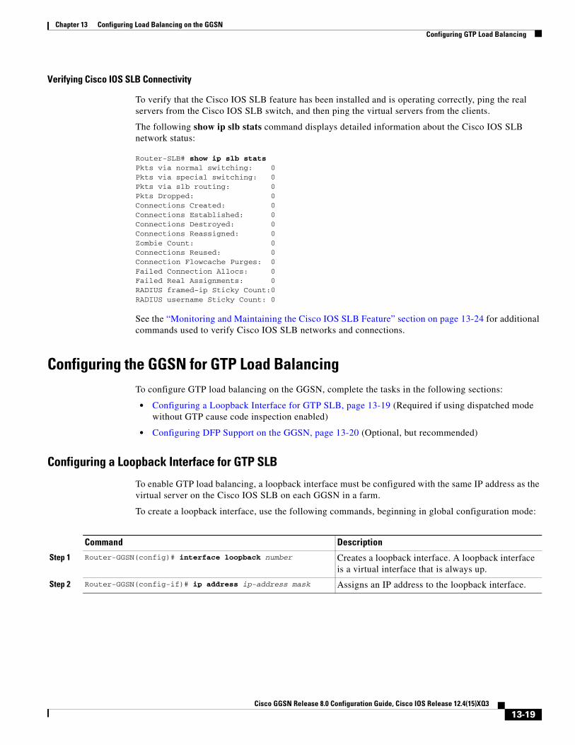
Chapter 13 Configuring Load Balancing on the GGSNConfiguring GTP Load Balancing
Verifying Cisco IOS SLB Connectivity
To verify that the Cisco IOS SLB feature has been installed and is operating correctly, ping the real servers from the Cisco IOS SLB switch, and then ping the virtual servers from the clients.
The following show ip slb stats command displays detailed information about the Cisco IOS SLB network status:
Router-SLB# show ip slb statsPkts via normal switching: 0Pkts via special switching: 0Pkts via slb routing: 0Pkts Dropped: 0Connections Created: 0Connections Established: 0Connections Destroyed: 0Connections Reassigned: 0Zombie Count: 0Connections Reused: 0Connection Flowcache Purges: 0Failed Connection Allocs: 0Failed Real Assignments: 0RADIUS framed-ip Sticky Count:0RADIUS username Sticky Count: 0
See the “Monitoring and Maintaining the Cisco IOS SLB Feature” section on page 13-24 for additional commands used to verify Cisco IOS SLB networks and connections.
Configuring the GGSN for GTP Load BalancingTo configure GTP load balancing on the GGSN, complete the tasks in the following sections:
• Configuring a Loopback Interface for GTP SLB, page 13-19 (Required if using dispatched mode without GTP cause code inspection enabled)
• Configuring DFP Support on the GGSN, page 13-20 (Optional, but recommended)
Configuring a Loopback Interface for GTP SLB
To enable GTP load balancing, a loopback interface must be configured with the same IP address as the virtual server on the Cisco IOS SLB on each GGSN in a farm.
To create a loopback interface, use the following commands, beginning in global configuration mode:
Command Description
Step 1 Router-GGSN(config)# interface loopback number Creates a loopback interface. A loopback interface is a virtual interface that is always up.
Step 2 Router-GGSN(config-if)# ip address ip-address mask Assigns an IP address to the loopback interface.
13-19Cisco GGSN Release 8.0 Configuration Guide, Cisco IOS Release 12.4(15)XQ3

Chapter 13 Configuring Load Balancing on the GGSNConfiguring GTP Load Balancing
Configuring DFP Support on the GGSN
To configure DFP support for GTP SLB, you must complete the following tasks:
• Configuring the GGSN as a DFP Agent, page 13-20
• Configuring the Maximum DFP Weight for a GGSN, page 13-20
• Configuring the Maximum Number of PDP Contexts for a GGSN, page 13-21
Configuring the GGSN as a DFP Agent
For complete information on configuring a DFP agent, refer to the DFP Agent Subsystem feature module.
To define the port number to be used by the DFP manager (the Cisco IOS SLB in this instance) to connect to the DFP agent, enter the following commands in order, beginning in global configuration mode:
Configuring the Maximum DFP Weight for a GGSN
If you use DFP with GTP load balancing, each GGSN that acts as a DFP agent has a maximum weight that it can send to a DFP manager. For each GGSN, you can accept the default maximum weight, or you can specify a different maximum weight.
To specify the maximum weight for a GGSN, use the following command in global configuration mode on the GGSN:
Command Description
Step 1 Router-GGSN(config)# ip dfp agent gprs Identifies a DFP agent subsystem and initiates DFP agent configuration mode.
Step 2 Router-GGSN(config-dfp)# interval seconds (Optional) Configures a DFP agent weight recalculation interval.
Step 3 Router-GGSN(config-dfp)# password [0|7] password [timeout]
Optional) Configures a DFP agent password for MD5 authentication.
Step 4 Router-GGSN(config-dfp)# port port-number Defines the port number to be used by the DFP manager to connect to the DFP agent.
Step 5 Router-GGSN(config-dfp)# inservice Enables the DFP agent for communication with a DFP manager. A DFP agent is inactive until both of the following conditions are met:
• The DFP agent has been enabled using the inservice (DFP agent) command.
• The client subsystem has changed the DFP agent's state to ACTIVE.
Command PurposeRouter-GGSN(config)# gprs dfp max-weight [max-weight-value]
Specifies the maximum weight of a GGSN that is acting as a DFP agent.
13-20Cisco GGSN Release 8.0 Configuration Guide, Cisco IOS Release 12.4(15)XQ3
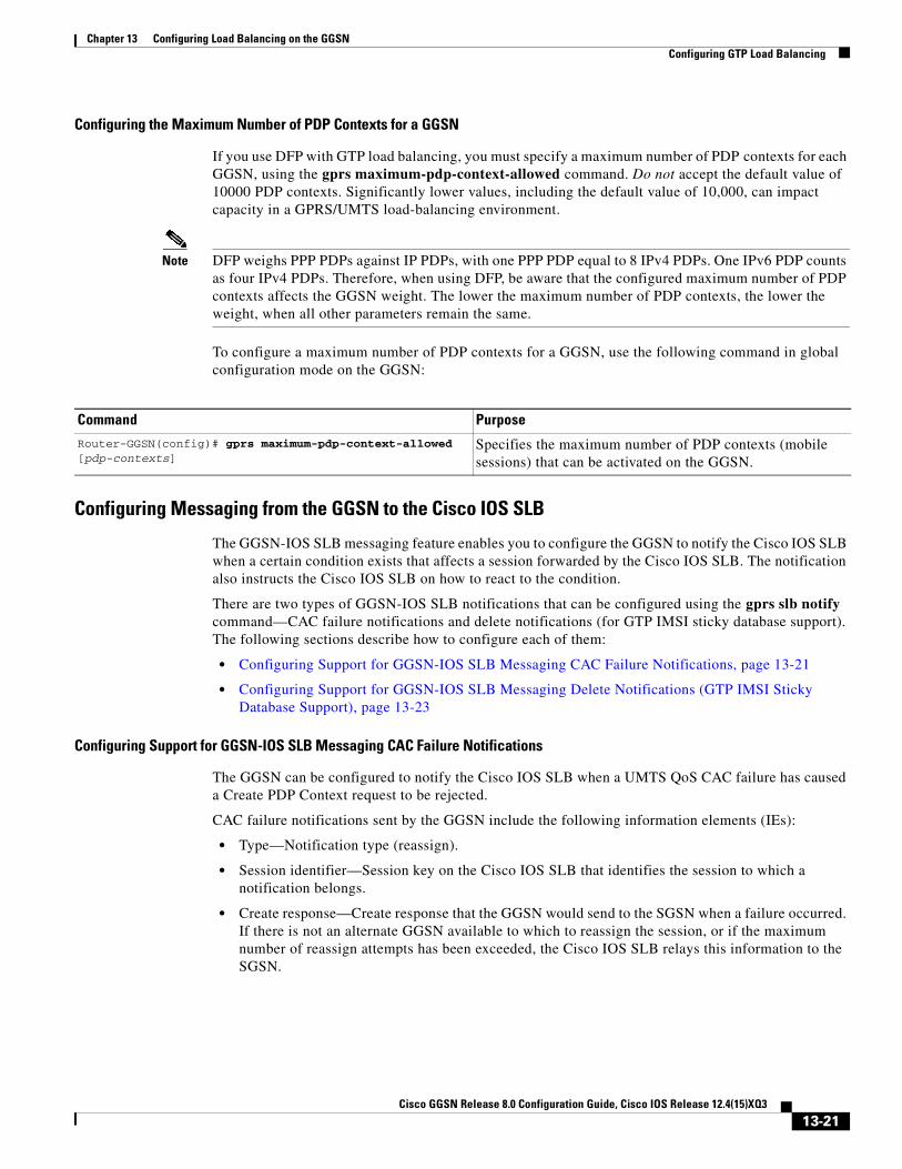
Chapter 13 Configuring Load Balancing on the GGSNConfiguring GTP Load Balancing
Configuring the Maximum Number of PDP Contexts for a GGSN
If you use DFP with GTP load balancing, you must specify a maximum number of PDP contexts for each GGSN, using the gprs maximum-pdp-context-allowed command. Do not accept the default value of 10000 PDP contexts. Significantly lower values, including the default value of 10,000, can impact capacity in a GPRS/UMTS load-balancing environment.
Note DFP weighs PPP PDPs against IP PDPs, with one PPP PDP equal to 8 IPv4 PDPs. One IPv6 PDP counts as four IPv4 PDPs. Therefore, when using DFP, be aware that the configured maximum number of PDP contexts affects the GGSN weight. The lower the maximum number of PDP contexts, the lower the weight, when all other parameters remain the same.
To configure a maximum number of PDP contexts for a GGSN, use the following command in global configuration mode on the GGSN:
Configuring Messaging from the GGSN to the Cisco IOS SLB
The GGSN-IOS SLB messaging feature enables you to configure the GGSN to notify the Cisco IOS SLB when a certain condition exists that affects a session forwarded by the Cisco IOS SLB. The notification also instructs the Cisco IOS SLB on how to react to the condition.
There are two types of GGSN-IOS SLB notifications that can be configured using the gprs slb notify command—CAC failure notifications and delete notifications (for GTP IMSI sticky database support). The following sections describe how to configure each of them:
• Configuring Support for GGSN-IOS SLB Messaging CAC Failure Notifications, page 13-21
• Configuring Support for GGSN-IOS SLB Messaging Delete Notifications (GTP IMSI Sticky Database Support), page 13-23
Configuring Support for GGSN-IOS SLB Messaging CAC Failure Notifications
The GGSN can be configured to notify the Cisco IOS SLB when a UMTS QoS CAC failure has caused a Create PDP Context request to be rejected.
CAC failure notifications sent by the GGSN include the following information elements (IEs):
• Type—Notification type (reassign).
• Session identifier—Session key on the Cisco IOS SLB that identifies the session to which a notification belongs.
• Create response—Create response that the GGSN would send to the SGSN when a failure occurred. If there is not an alternate GGSN available to which to reassign the session, or if the maximum number of reassign attempts has been exceeded, the Cisco IOS SLB relays this information to the SGSN.
Command Purpose
Router-GGSN(config)# gprs maximum-pdp-context-allowed [pdp-contexts]
Specifies the maximum number of PDP contexts (mobile sessions) that can be activated on the GGSN.
13-21Cisco GGSN Release 8.0 Configuration Guide, Cisco IOS Release 12.4(15)XQ3

Chapter 13 Configuring Load Balancing on the GGSNConfiguring GTP Load Balancing
The way you configure support for CAC failure notifications depends on whether the Cisco IOS SLB is operating in dispatched mode or directed server NAT mode. For information on each procedure, see the following sections:
• Configuring CAC Failure Notification Support when the Cisco IOS SLB is in Dispatched Mode, page 13-22
• Configuring CAC Failure Notification Support when the Cisco IOS SLB is in Directed Server NAT Mode, page 13-22
Configuring CAC Failure Notification Support when the Cisco IOS SLB is in Dispatched Mode
If the Cisco IOS SLB is functioning in dispatched mode, the virtual server that forwarded the Create PDP Context request to the GGSN is known to the GGSN, and the GGSN can send CAC failure notifications directly to the server.
To configure the GGSN to send CAC failure notifications to the Cisco IOS SLB when the Cisco IOS SLB is in dispatched mode, use the following command in global configuration mode:
To enable CAC failure notification support on the Cisco IOS SLB, use the following command in virtual server mode:
Configuring CAC Failure Notification Support when the Cisco IOS SLB is in Directed Server NAT Mode
If the Cisco IOS SLB is functioning in directed server NAT mode, the virtual server is not known to the GGSN. Therefore, in addition to configuring the GGSN to send CAC failure notifications to the Cisco IOS SLB, a list of virtual servers must be defined on the GGSN using the gprs slb vserver global configuration command, and the Cisco IOS SLB mode of operation must be defined using the gprs slb mode global configuration command.
Note If the Cisco IOS SLB operation mode and virtual servers are not defined on the GGSN when the Cisco IOS SLB is functioning in directed server NAT mode, support for CAC failure notification is not enabled, even if the gprs slb notify cac-failure and gtp notification cac commands are configured.
Command Description
Step 1 Router-GGSN(config)# gprs slb mode dispatched Defines dispatched as the Cisco IOS SLB operation mode for GGSN-IOS SLB messaging.
Note The default is dispatched mode.
Step 2 Router-GGSN(config)# gprs slb notify cac-failure Enables the GGSN to notify the Cisco IOS SLB when a UMTS QoS CAC failure has caused a Create PDP Context request to be rejected.
Command Purpose
Router-SLB(config-slb-vserver)# gtp notification cac count
Enables support of GGSN-IOS SLB messaging CAC failure notifications and configures the maximum number of times a rejected Create PDP Context can be reassigned to a new real GGSN. The default is 2 (which is 3 real selections per session, including the initial send).
13-22Cisco GGSN Release 8.0 Configuration Guide, Cisco IOS Release 12.4(15)XQ3

Chapter 13 Configuring Load Balancing on the GGSNConfiguring GTP Load Balancing
To enable the GGSN to send CAC failure notifications to the Cisco IOS SLB when the Cisco IOS SLB is in directed server NAT mode, use the following commands while in global configuration mode:
To enable CAC failure notification support on the Cisco IOS SLB, use the following command in virtual server mode:
Configuring Support for GGSN-IOS SLB Messaging Delete Notifications (GTP IMSI Sticky Database Support)
When support for delete notifications is configured on the GGSN and the Cisco IOS SLB, a sticky database entry is created on the Cisco IOS SLB when the first Create PDP Context request from a subscriber is received. When the last PDP context of that IMSI is deleted on the GGSN, the GGSN sends a delete notification to the Cisco IOS SLB that instructs the Cisco IOS SLB to remove the sticky entry from the database.
Note This configuration requires that the virtual virtual server configuration command be configured with the service gtp keywords specified.
Note If the sticky gtp imsi command is configured under multiple vservers, the group number configuration facilitate sharing of the sticky object in the event the same MS connects through different vservers. All vservers that have the same sticky group number share the sticky IMSI entry for a user.
Command Description
Step 1 Router-GGSN(config)# gprs slb mode directed Defines directed server NAT as the Cisco IOS SLB operation mode for GGSN-IOS SLB messaging.
Note The default is dispatched mode.
Step 2 Router-GGSN(config)# gprs slb notify cac-failure Enables the GGSN to notify the Cisco IOS SLB when a UMTS QoS CAC failure has caused a Create PDP Context request to be rejected.
Step 3 Router-GGSN(config)# gprs slb vserver ip_address [next-hop ip ip-address [vrf name]]
Configures the Cisco IOS SLB virtual server(s) to be notified by a GGSN when the condition defined using the gprs slb notify command occurs.
Optionally, also configures the IP address of the next-hop that can be used to reach the virtual server and specifies the VPN routing and forwarding instance.
Command Purpose
Router-SLB(config-slb-vserver)# gtp notification cac count
Enables support of GGSN-IOS SLB messaging CAC failure notifications and configures the maximum number of times a rejected Create PDP Context can be reassigned to a new real GGSN. The default is 2 (including the initial send, 3 real selections per session).
13-23Cisco GGSN Release 8.0 Configuration Guide, Cisco IOS Release 12.4(15)XQ3

Chapter 13 Configuring Load Balancing on the GGSNMonitoring and Maintaining the Cisco IOS SLB Feature
To configure the GGSN to send a delete notification to the Cisco IOS SLB when the last PDP context of an IMSI is deleted on the GGSN, complete the following tasks while in global configuration mode:
To configure GTP IMSI sticky database support on the Cisco IOS SLB, complete the following task while in virtual server configuration mode:
Monitoring and Maintaining the Cisco IOS SLB FeatureTo clear, obtain, and display GTP SLB information on the GGSN, use the following commands in privileged EXEC mode:
Command Description
Step 1 Router-GGSN(config)# gprs slb mode {dispatched | directed}
Defines the Cisco IOS SLB operation mode for GGSN-IOS SLB messaging. The default is dispatched mode.
Step 2 Router-GGSN(config)# gprs slb notify session-deletion Configures the GGSN to send a delete notification message to the Cisco IOS SLB when the last PDP context associated with an IMSI is deleted.
Step 3 Router-GGSN(config)# gprs slb vservers ip_address [next-hop ip ip-address [vrf name]]
Configures the Cisco IOS SLB virtual server(s) to be notified by a GGSN when the condition defined using the gprs slb notify command occurs.
Optionally, also configures the IP address of the next-hop that can be used to reach the virtual server and specifies the VPN routing and forwarding instance.
Command PurposeRouter-SLB(config-slb-vserver)# sticky gtp imsi [group number]
Enables Cisco IOS SLB to load-balance GTP Create PDP Context requests to the same real server that processed all previous create requests for a given IMSI.
Command Purpose
Router-GGSN# clear gprs slb statistics Clears Cisco IOS SLB statistics.
Router-GGSN# show gprs slb detail Displays all Cisco IOS SLB-related information, such as operation mode, virtual server addresses for GGSN-IOS SLB messaging, SLB notifications, and statistics.
Router-GGSN# show gprs slb mode Displays the Cisco IOS SLB mode of operation.
Router-GGSN# show gprs slb statistics Displays Cisco IOS SLB statistics.
Router-GGSN# show gprs slb vservers Displays a list of defined Cisco IOS SLB virtual servers for GGSN-IOS SLB messaging.
13-24Cisco GGSN Release 8.0 Configuration Guide, Cisco IOS Release 12.4(15)XQ3

Chapter 13 Configuring Load Balancing on the GGSNMonitoring and Maintaining the Cisco IOS SLB Feature
To obtain and display information about the GTP SLB on the Cisco IOS SLB, use the following commands in privileged EXEC mode on the Cisco IOS SLB:
Command PurposeRouter-SLB# show ip slb conns [vserver virtual_server-name | client ip-address | firewall firewallfarm-name] [detail]
Displays all connections handled by Cisco IOS SLB, or, optionally, only the connections associated with a particular virtual server or client.
Router-SLB# show ip slb dfp [agent agent_ip_address port-number | manager manager_ip_address | detail | weights]
Displays information about DFP and DFP agents, and about the weights assigned to real servers.
Router-SLB# show ip slb gtp {gsn [gsn-ip-address] | nsapi [nsapi-key] [detail]
Displays Cisco IOS SLB GTP information when GTP load balancing with cause code inspection is enabled.
Router-SLB# show ip slb map [id] Displays information about Cisco IOS SLB protocol maps.
Router-SLB# show ip slb reals [sfarm server-farm] [detail] Displays information about the real servers defined to Cisco IOS SLB.
Router-SLB# show ip slb replicate Displays information about the Cisco IOS SLB replication configuration.
Router-SLB# show ip slb serverfarms [name serverfarm-name] [detail]
Displays information about the server farms defined to Cisco IOS SLB.
Router-SLB show ip slb sessions [gtp | gtp-inspect | radius] [vserver virtual-server] [client ip-addr netmask] [detail]
Displays information about sessions handled by Cisco IOS SLB.
Note With GTP load balancing without cause code inspection, a session lasts no longer than the duration of the virtual server GTP idler time specified using the idle gtp request command.
Router=SLB# show ip slb stats Displays Cisco IOS SLB statistics.
Router-SLB# show ip slb sticky gtp imsi [id imsi] Displays only entries of the Cisco IOS SLB sticky database associated with the Cisco IOS SLB GTP IMSI sticky database, and shows all of the Network Service Access Point Identifiers (NSAPIs) that the user has used as primary PDPs.
Optionally, displays only those sticky database entries associated with the specified IMSI.
Router-SLB# show ip slb vserver [name virtual_server] [redirect] [detail]
Displays information about the virtual servers defined to Cisco IOS SLB.
13-25Cisco GGSN Release 8.0 Configuration Guide, Cisco IOS Release 12.4(15)XQ3

Chapter 13 Configuring Load Balancing on the GGSNConfiguration Examples
Configuration ExamplesThis section provides an example of the GGSN Cisco IOS SLB examples. For complete descriptions of the GGSN commands in this section, refer to the Cisco GGSN Release Command Reference. For complete descriptions of the Cisco IOS SLB commands in this section, refer to the IOS Server Load Balancing feature module documentation.
This section includes examples of Cisco IOS SLB with GTP load balancing and NAT configured on the Cisco 7600 platform:
• Cisco IOS SLB Configuration Example, page 13-26
• GGSN1 Configuration Example, page 13-27
Cisco IOS SLB Configuration Example
hostname 7600-a!ip slb probe PINGPROBE ping interval 3 faildetect 3!ip slb serverfarm SAMI1 nat server probe PINGPROBE! real 9.9.9.72 reassign 4 faildetect numconns 255 numclients 8 inservice! real 9.9.9.73 reassign 4 faildetect numconns 255 numclients 8 inservice! real 9.9.9.74 reassign 4 faildetect numconns 255 numclients 8 inservice! real 9.9.9.75 reassign 4 faildetect numconns 255 numclients 8 inservice! real 9.9.9.76 reassign 4 faildetect numconns 255 numclients 8 inservice!ip slb vserver V0-GGSN virtual 10.10.10.10 udp 3386 service gtp serverfarm SAMI1 idle gtp request 100 inservice!ip slb vserver V1-GGSN virtual 10.10.10.10 udp 2123 service gtp serverfarm SAMI1 idle gtp request 100
13-26Cisco GGSN Release 8.0 Configuration Guide, Cisco IOS Release 12.4(15)XQ3

Chapter 13 Configuring Load Balancing on the GGSNConfiguration Examples
inservice!ip slb dfp password ciscodfp 0 agent 9.9.9.72 1111 30 0 10 agent 9.9.9.73 1111 30 0 10 agent 9.9.9.74 1111 30 0 10 agent 9.9.9.75 1111 30 0 10 agent 9.9.9.76 1111 30 0 10!interface FastEthernet9/36 description TO SGSN no ip address switchport switchport access vlan 302!interface Vlan101 description Vlan to GGSN for GN ip address 10.1.1.1 255.255.255.0!interface Vlan302 ip address 40.0.2.1 255.255.255.0!router ospf 300 log-adjacency-changes summary-address 9.9.9.0 255.255.255.0 redistribute static subnets route-map GGSN-routes network 40.0.2.0 0.0.0.255 area 300 network 40.0.3.0 0.0.0.255 area 300!ip route 9.9.9.72 255.255.255.255 10.1.1.72ip route 9.9.9.73 255.255.255.255 10.1.1.73ip route 9.9.9.74 255.255.255.255 10.1.1.74ip route 9.9.9.75 255.255.255.255 10.1.1.75ip route 9.9.9.76 255.255.255.255 10.1.1.76!access-list 1 permit 9.9.9.0 0.0.0.255!route-map GGSN-routes permit 10 match ip address 1!!
GGSN1 Configuration Example
!ip dfp agent gprs port 1111 password ciscodfp 0 inservice!interface Loopback100 description GPRS GTP V-TEMPLATE IP ADDRESS ip address 9.9.9.72 255.255.255.0!interface GigabitEthernet0/0.2 description Gn Interface encapsulation dot1Q 101 ip address 10.1.1.72 255.255.255.0 no cdp enable!interface Virtual-Template1 description GTP v-access
13-27Cisco GGSN Release 8.0 Configuration Guide, Cisco IOS Release 12.4(15)XQ3

Chapter 13 Configuring Load Balancing on the GGSNConfiguration Examples
ip unnumbered Loopback100 encapsulation gtp gprs access-point-list gprs!! route to SGSNsip route 40.1.2.1 255.255.255.255 10.1.1.1ip route 40.2.2.1 255.255.255.255 10.1.1.1
13-28Cisco GGSN Release 8.0 Configuration Guide, Cisco IOS Release 12.4(15)XQ3

Cisco GGSN Release 8.0 Configu
A
P P E N D I X A Monitoring NotificationsThis appendix describes enabling and monitoring Gateway GPRS Support Node (GGSN) SNMP notifications in order to manage GPRS/UMTS-related issues. SNMP uses notifications to report events on a managed device. The notifications are traps or informs for different events.
Note This appendix covers enabling and monitoring GGSN SNMP notifications only. Additional types of SNMP notifications can be enabled on your Cisco router. For more information about the types of SNMP notifications you can enable, see the Cisco IOS Configuration Fundamentals, Release 12.4 documentation. Additionally, to display a list of notifications available on your Cisco router, enter the snmp-server enable traps ? command.
This appendix contains the following sections:
• SNMP Overview, page A-1
• Configuring MIB Support, page A-6
• Enabling SNMP Support, page A-9
• Enabling and Disabling SNMP Notifications, page A-9
• GGSN Notifications, page A-11
SNMP OverviewThe Simple Network Management Protocol (SNMP) is an application-layer protocol that provides a standardized framework and a common language used for monitoring and managing devices in a network.
The SNMP framework has three parts:
• SNMP manager—A system used to control and monitor the activities of network hosts using SNMP. The most common managing system is called a Network Management System (NMS). The term NMS can be applied to either a dedicated device used for network management, or the applications used on a network-management device. A variety of network management applications are available for use with SNMP. These features range from simple command-line applications to feature-rich graphical user interfaces (such as the CiscoWorks2000 line of products).
A-1ration Guide, Cisco IOS Release 12.4(15)XQ3

Appendix A Monitoring Notifications SNMP Overview
• SNMP agent—A software component in a managed device that maintains the data for the device and reports the data, as needed, to managing systems. The agent and MIB reside on the routing device (router, access server, or switch). To enable the SNMP agent on a managed device, you must define the relationship between the manager and the agent (see the “Enabling SNMP Support” section on page A-9).
• Management Information Base (MIB)—Collection of network-management information, organized hierarchically.
Instead of defining a large set of commands, SNMP places all operations in a get-request, get-next-request, and set-request format. For example, an SNMP manager can get a value from an SNMP agent or set a value in that SNMP agent.
MIB DescriptionA Management Information Base (MIB) is a collection of network-management information, organized hierarchically. The MIB consists of collections of managed objects identified by object identifiers. MIBs are accessed using a network-management protocol such as SNMP. A managed object (sometimes called a MIB object or an object) is one of a number of characteristics of a managed device, such as a router. Managed objects comprise one or more object instances, which are essentially variables. The Cisco implementation of SNMP uses the definitions of MIB II variables described in RFC 1213.
MIBs can contain two types of managed objects:
• Scalar objects—Define a single object instance (for example, ifNumber in the IF-MIB and bgpVersion in the BGP4-MIB).
• Columnar objects—Defines a MIB table that contains no rows or more than one row, and each row can contain one or more scalar objects, (for example, ifTable in the IF-MIB defines the interface).
System MIB variables are accessible through SNMP as follows:
• Accessing a MIB variable—Function is initiated by the SNMP agent in response to a request from the NMS. The agent retrieves the value of the requested MIB variable and responds to the NMS with that value.
• Setting a MIB variable—Function is initiated by the SNMP agent in response to a message from the NMS. The SNMP agent changes the value of the MIB variable to the value requested by the NMS.
SNMP NotificationsAn SNMP agent can notify the manager when important system events occur, such as the following:
• An interface or card starts or stops running
• Temperature thresholds are crossed
• Authentication failures occur
When an agent detects an alarm condition, the agent:
• Logs information about the time, type, and severity of the condition
• Generates a notification message, which it then sends to a designated IP host
A-2Cisco GGSN Release 8.0 Configuration Guide, Cisco IOS Release 12.4(15)XQ3

Appendix A Monitoring Notifications SNMP Overview
SNMP notifications are sent as either:
• Traps—Unreliable messages, which do not require receipt acknowledgment from the SNMP manager.
• Informs—Reliable messages, which are stored in memory until the SNMP manager issues a response. Informs use more system resources than traps.
Note Many commands use the word traps in the command syntax. Unless there is an option in the command to select either traps or informs, the keyword traps refers to either traps, informs, or both. Use the snmp-server host command to specify whether to send SNMP notifications as traps or informs.
When an agent detects an alarm condition, it logs information about the time, type, and severity of the condition and generates a notification message, which it then sends to a designated IP host.
SNMP notifications can be sent as either traps or informs. See the “Enabling SNMP Support” section on page A-9 for instructions on how to enable traps on the GGSN. See the “GGSN Notifications” section on page A-11 for information about GGSN traps.
The Cisco implementation of SNMP uses the definitions of SNMP traps described in RFC 1215.
SNMP VersionsCisco IOS software supports the following versions of SNMP:
• SNMPv1—The Simple Network Management Protocol: An Internet standard, defined in RFC 1157. Security is based on community strings.
• SNMPv2c—The community-string based administrative framework for SNMPv2. SNMPv2c is an update of the protocol operations and data types of SNMPv2p (SNMPv2 classic), and uses the community-based security model of SNMPv1.
• SNMPv3—Version 3 of SNMP. SNMPv3 uses the following security features to provide secure access to devices:
– Message integrity—Ensuring that a packet has not been tampered with in transit.
– Authentication—Determining that the message is from a valid source.
– Encryption—Scrambling the contents of a packet to prevent it from being learned by an unauthorized source.
A-3Cisco GGSN Release 8.0 Configuration Guide, Cisco IOS Release 12.4(15)XQ3

Appendix A Monitoring Notifications SNMP Overview
SNMPv1 and SNMPv2c
Both SNMPv1 and SNMPv2c use a community-based form of security. The community of managers who are able to access the agent MIB is defined by an IP address Access Control List and password.
SNMPv2c support includes a bulk-retrieval mechanism and more detailed error message reporting to management stations. The bulk-retrieval mechanism supports the retrieval of tables and large quantities of information, minimizing the number of round-trip transmissions required. SNMPv2c improved error handling support includes expanded error codes that distinguish different kinds of error conditions; these conditions are reported through a single error code in SNMPv1. Error return codes now report the error type. Three kinds of exceptions are also reported:
• no such object exceptions
• no such instance exceptions
• end of MIB view exceptions
SNMPv3
SNMPv3 provides the following security models and security levels:
• Security model—Authentication strategy that is set up for a user and the group in which the user resides.
• Security level—Permitted level of security within a security model.
A combination of a security model and a security level determines the security mechanism to be employed when handling an SNMP packet.
SNMP Security Models and Levels
Table 0-1 describes the security models and levels provided by the different SNMP versions.
Table 0-1 SNMP Security Models and Levels
Model Level Authentication Encryption Description
v1 noAuthNoPriv Community string
No Uses match on community string for authentication.
v2c noAuthNoPriv Community string
No Uses match on community string for authentication.
v3 noAuthNoPriv User name No Uses match on user name for authentication.
v3 authNoPriv MD5 or SHA No Provides authentication based on HMAC-MD5 or HMAC-SHA algorithm.
v3 authPriv MD5 or SHA DES Provides authentication based on HMAC-MD5 or HMAC-SHA algorithm. Also provides DES 56-bit encryption based on CBC-DES (DES-56) standard.
A-4Cisco GGSN Release 8.0 Configuration Guide, Cisco IOS Release 12.4(15)XQ3

Appendix A Monitoring Notifications SNMP Overview
You must configure the SNMP agent to use the version of SNMP supported by the management station. An agent can communicate with multiple managers; for this reason, you can configure the Cisco IOS software to support communications with one management station using the SNMPv1 protocol, one using the SNMPv2c protocol, and another using SMNPv3.
Requests for CommentsMIB modules are written in the SNMP MIB module language, and are typically defined in Request For Comments (RFC) documents submitted to the Internet Engineering Task Force (IETF). RFCs are written by individuals or groups for consideration by the Internet Society and the Internet community as a whole. Before being given RFC status, recommendations are published as Internet Draft (I-D) documents. RFCs that have become recommended standards are also labeled as standards (STD) documents. For more information, see the Internet Society and IETF websites (http://www.isoc.org and http://www.ietf.org).
We provide private MIB extensions with each Cisco system. Cisco enterprise MIBs comply with the guidelines described in the relevant RFCs unless otherwise noted in the documentation.
Object IdentifiersAn object identifier (OID) uniquely identifies a MIB object on a managed network device. The OID identifies the MIB object’s location in the MIB hierarchy, and provides a means of accessing the MIB object in a network of managed devices:
• Standard RFC MIB OIDs are assigned by the Internet Assigned Numbers Authority (IANA)
• Enterprise MIB OIDs are assigned by Cisco Assigned Numbers Authority (CANA).
Each number in the OID corresponds to a level of MIB hierarchy. For example, the OID 1.3.6.1.4.1.9.9.xyz represents the xyz-MIB whose location in the MIB hierarchy is as follows. Note that the numbers in parentheses are included only to help show correspondence to the MIB hierarchy. In actual use, OIDs are represented as numerical values only.
iso(1).org(3).dod(6).internet(1).private(4).enterprises(1).cisco(9).ciscoMgt(9).nn-MIB
You can uniquely identify a managed object, such as ifNumber in the IF-MIB, by its object name (iso.org.dod.internet.mgmt.enterprises.interfaces.ifNumber) or by its OID (1.3.6.1.2.1.2.1).
For a list of OIDs assigned to MIB objects, go to the following URL:
ftp://ftp.cisco.com/pub/mibs/oid/
Related Information and Useful LinksThe following URL provides access to general information about Cisco MIBs. Use the links on this page to access MIBs for download, and to access related information (such as application notes and OID listings).
• http://www.cisco.com/public/sw-center/netmgmt/cmtk/mibs.shtml
A-5Cisco GGSN Release 8.0 Configuration Guide, Cisco IOS Release 12.4(15)XQ3
Appendix A Monitoring Notifications Configuring MIB Support
TAC Information and FAQs
The following URLs provide access to SNMP information developed by the Cisco Technical Assistance Center (TAC):
• http://www.cisco.com/warp/public/477/SNMP/index.html is the Cisco TAC page for SNMP. It provides links to general SNMP information and tips for using SNMP to gather data.
• http://www.cisco.com/warp/public/477/SNMP/mibs_9226.shtml is a list of frequently asked questions (FAQs) about Cisco MIBs.
SNMP Configuration Information
The following URLs provide information about configuring SNMP:
• http://www.cisco.com/univercd/cc/td/doc/product/software/ios120/12cgcr/fun_c/fcprt3/fcmonitr.htmprovides general information about configuring SNMP support. It is part of the Cisco IOS Configuration Fundamentals Configuration Guide.
• http://www.cisco.com/univercd/cc/td/doc/product/software/ios120/12cgcr/fun_r/frprt3/frmonitr.htm provides information about SNMP commands. It is part of the Cisco IOS Configuration Fundamentals Command Reference.
Configuring MIB SupportThis chapter describes how to configure SNMP and MIB support on a Cisco router. It includes the following sections:
• Determining MIBs Included for Cisco IOS Releases, page A-6
• Downloading and Compiling MIBs, page A-7
• Enabling SNMP Support, page A-9
Determining MIBs Included for Cisco IOS ReleasesFollow these steps to determine which MIBs are included in the Cisco IOS release you are using:
Step 1 Go to the Feature Navigator home page http://tools.cisco.com/ITDIT/MIBS/servlet/index.
Step 2 Click MIB Locator to launch the application. The MIB Locator application allows you to find a MIB in the following three ways:
a. By release, platform family, and feature set—From the MIB Locator page:
• Click the drop-down menu and select the desired Cisco IOS software release.
• From the Platform Family menu, select 7600-SAMI. If you select the platform first, the system displays only those releases and feature sets that apply to the platform you have selected.
• From the Feature Set menu, select the appropriate GGSN release.
A-6Cisco GGSN Release 8.0 Configuration Guide, Cisco IOS Release 12.4(15)XQ3
Appendix A Monitoring Notifications Configuring MIB Support
b. By image name—From the MIB Locator page, enter the GGSN image name you are using into the Search by Image Name field and click Submit: (the following image name is an example):
c6svcsami-g8is-mz.124-15.XQ.bin
c. By MIB name—From the MIB Locator page, search for the MIB from the list of MIBs in the Search for a MIB menu. You can select one, or for a multiple selection, hold down the CTRL key, then click Submit.
Note After you make a selection, follow the links and instructions.
Downloading and Compiling MIBsThe following sections provide information about how to download and compile MIBs for the GGSN:
• Considerations for Working with MIBs
• Downloading MIBs
• Compiling MIBs
Considerations for Working with MIBs
While working with MIBs, consider the following:
Mismatches on Datatype Definitions
• Mismatches on datatype definitions might cause compiler errors or warning messages. Although Cisco MIB datatype definitions are not mismatched, standard RFC MIBs do mismatch. For example:
MIB A defines: SomeDatatype ::= INTEGER(0..100) MIB B defines: SomeDatatype ::= INTEGER(1..50)
This example is considered to be a trivial error and the MIB loads successfully with a warning message.
The next example is considered a nontrivial error (even though the two definitions are essentially equivalent), and the MIB is not successfully parsed.
MIB A defines: SomeDatatype ::= DisplayString MIB B defines: SomeDatatype ::= OCTET STRING (SIZE(0..255))
If your MIB compiler treats these as errors, or you want to delete the warning messages, edit one of the MIBs that define this same datatype so that the definitions match.
• Many MIBs import definitions from other MIBs. If your management application requires MIBs to be loaded, and you experience problems with undefined objects, you might want to load the following MIBs in this order:
SNMPv2-SMI.my SNMPv2-TC.my SNMPv2-MIB.my RFC1213-MIB.my IF-MIB.my
A-7Cisco GGSN Release 8.0 Configuration Guide, Cisco IOS Release 12.4(15)XQ3

Appendix A Monitoring Notifications Configuring MIB Support
CISCO-SMI.my CISCO-PRODUCTS-MIB.my CISCO-TC.my
• For additional information and SNMP technical tips, from the Locator page, click SNMP MIB Technical Tips and follow the links or go to the following URL:
http://www.cisco.com/pcgi-bin/Support/browse/psp_view.pl?p=Internetworking:SNMP&s=Implementation_and_Configuration#Samples_and_Tips
• For a list of SNMP object identifiers (OIDs) assigned to MIB objects, go to the following URL and click on SNMP Object Navigator and follow the links:
http://tools.cisco.com/ITDIT/MIBS/servlet/index
Note You must have a Cisco CCO name and password to access the MIB Locator.
• For information about how to download and compile Cisco MIBs, go to the following URL:
http://www.cisco.com/warp/public/477/SNMP/mibcompilers.html
Downloading MIBs
Follow these steps to download the MIBs onto your system if they are not already there:
Step 1 Review the considerations in the previous section (“Considerations for Working with MIBs”).
Step 2 Go to one of the following Cisco URLs. If the MIB you want to download is not there, try the other URL; otherwise, go to one of the URLs in Step 5.
ftp://ftp.cisco.com/pub/mibs/v2 ftp://ftp.cisco.com/pub/mibs/v1
Step 3 Click the link for a MIB to download that MIB to your system.
Step 4 Select File > Save or File > Save As to save the MIB on your system.
Step 5 You can download industry-standard MIBs from the following URLs:
• http://www.ietf.org
• http://www.atmforum.com
Compiling MIBs
If you plan to integrate the Cisco router with an SNMP-based management application, then you must also compile the MIBs for that platform. For example, if you are running HP OpenView on a UNIX operating system, you must compile platform MIBs with the HP OpenView Network Management System (NMS). For instructions, see the NMS documentation.
A-8Cisco GGSN Release 8.0 Configuration Guide, Cisco IOS Release 12.4(15)XQ3

Appendix A Monitoring Notifications Enabling SNMP Support
Enabling SNMP SupportThe following procedure summarizes how to configure the Cisco router for SNMP support.
For detailed information about SNMP commands, see the following Cisco documents:
• Cisco IOS Release 12.3 Configuration Fundamentals Configuration Guide, “Monitoring the Router and Network” section, available at the following URL:
http://www.cisco.com/univercd/cc/td/doc/product/software/ios122/122cgcr/ffun_c/index.htm
• Cisco IOS Release 12.3 Configuration Fundamentals Command Reference, Part 3: System Management Commands, “Router and Network Configuration Commands” section, available at the the following URL:
http://www.cisco.com/univercd/cc/td/doc/product/software/ios122/122cgcr/ffun_r/index.htm
To configure the Cisco router for SNMP support, follow these steps:
Step 1 Set up your basic SNMP configuration through the command line interface (CLI) on the router. Note that these basic configuration commands are issued for SNMPv2c. For SNMPv3, you must also set up SNMP users and groups. (See the preceding list of documents for command and setup information.)
a. Define SNMP read-only and read-write communities:
Router (config)# snmp-server community Read_Only_Community_Name roRouter (config)# snmp-server community Read_Write_Community_Name rw
b. Configure SNMP views (to limit the range of objects accessible to different SNMP user groups):
Router (config)# snmp-server view view_name oid-tree {included | excluded}
Enabling and Disabling SNMP NotificationsTo enable and disable SNMP Notifications, perform the tasks in the following sections:
• Enabling and Disabling GGSN Notifications via the CLI, page A-9
• Enabling and Disabling GGSN SNMP Notifications via SNMP, page A-10
• Enabling and Disabling GGSN SNMP Notifications via SNMP, page A-10
Enabling and Disabling GGSN Notifications via the CLITo use the command line interface (CLI) to enable the Cisco router to send GGSN SNMP notifications (traps or informs), perform the following steps.
Step 1 Make sure SNMP is configured on the router (see the “Enabling SNMP Support” section on page A-9).
Step 2 Identify (by IP address) the host to receive traps from the Cisco router:
Router(config)#snmp-server host host-address version SNMP version community/user(V3) udp-port <UDP port No>
A-9Cisco GGSN Release 8.0 Configuration Guide, Cisco IOS Release 12.4(15)XQ3

Appendix A Monitoring Notifications Enabling and Disabling SNMP Notifications
Step 3 Enable GGSN SNMP notifications on the Cisco router using the following command (enter a separate command for each type of notification you want to enable):
Router(config)#snmp-server enable traps gprs [apn | charging | ggsn | ggsn-apn | ggsn-general | ggsn-memory | ggsn-pdp | ggsn-service | gtp | csg | dcca]
Where:
• apn—Enables APN notifications.
• charging—Enables charging notifications.
• ggsn—Enables GGSN global notifications.
Note To prevent flooding, configuring the snmp-server enable traps gprs ggsn command enables all GGSN-related traps except for the cGgsnGlobalErrorNotif, cGgsnAccessPointNameNotif, and the cGgsnPacketDataProtocolNotif traps.
• ggsn-apn——Enables GGSN notifications specific to APN (cGgsnAccessPointNameNotif).
• ggsn-general—Enables GGSN general notifications (cGgsnGlobalErrorNotif).
• ggsn-pdp—Enables GGSN notifications specific to PDP (cGgsnPacketDataProtocolNotif).
• ggsn-service—Enables GGSN service-mode notifications.
• gtp—Enables GTP traps.
• csg—Enables GGSN CSG-specific notifications.
• dcca—Enables GGSN DCCA-specific notifications.
Note Issuing the snmp-server enable traps gprs command without a keyword option enables all GGSN SNMP notifications.
Step 4 To disable GGSN SNMP notifications on the Cisco router, enter the following command.
Router(config)# no snmp-server enable traps gprs
If you omit the notification type keyword (gprs in this example), all notifications are disabled.
Note We recommend that the snmp-server enable traps gtp command not be configured because all associated MIBs are deprecated.
Enabling and Disabling GGSN SNMP Notifications via SNMPAdditionally, GGSN SNMP Notifications can be enabled or disabled by setting the following objects to true(1) or false(2).
• cGgsnServiceNotifEnabled—Enables/disables GGSN service-mode notifications.
• cGgsnMemoryNotifEnabled—Enables/disable memory related notifications
• cGgsnGlobalErrorNotifEnabled—Enables GGSN general notifications
A-10Cisco GGSN Release 8.0 Configuration Guide, Cisco IOS Release 12.4(15)XQ3

Appendix A Monitoring Notifications GGSN Notifications
• cGgsnAccessPointNotifEnabled—Enables/disables cGgsnAccessPointNameNotif notification
• cGgsnPdpNotifEnabled—Enables/disables cGgsnPacketDataProtocolNotif notification
• cGgsnSACsgNotifEnabled— Enables/disables CSG state traps.
• cGgsnSADccaNotifEnabled—Enables/disables DCCA-related notifications
GGSN NotificationsThis section lists and briefly describes the notifications supported by GGSN MIBs and generated by the GGSN.
This section lists the following types of notifications:
• Global Notifications, page A-12
• Charging Notifications, page A-15
• Access-Point Notifications, page A-16
• Alarm Notifications, page A-17
A-11Cisco GGSN Release 8.0 Configuration Guide, Cisco IOS Release 12.4(15)XQ3

Appendix A Monitoring Notifications GGSN Notifications
Global NotificationsTable A-2 lists the global notifications supported by the CISCO-GGSN-MIB. To enable these notifica-tions to be sent, use the snmp-server enable traps grps global configuration command, with the ggsn, ggsn-apn, ggsn-memory, ggsn-pdp, ggsn-service, csg and/or dcca keyword option specified.
Note Issue a separate command for each keyword option.
Note cGgsnNotification (1.2.6.1.4.1.9.9.240.2.0.1) has been deprecated.
Table A-2 Global Notifications
Notification and Notification Objects Notes
cGgsnInServiceNotif (1.3.6.1.4.1.9.9.240.2.0.2) Sent when the GGSN is placed in operational (inService) mode.
The GGSN is placed in operational mode using the gprs service-mode operational global configuration command or by setting the cGgsnServiceMode object to inService(1).
The service mode is identified by cGgsnServiceModeStatus.
Enable the generation of this notification by setting cGgsnServiceNotifEnabled to true(1).
cGgsnMaintenanceNotif (1.3.6.1.4.1.9.9.240.2.0.3) Sent when the GGSN is placed is maintenance mode.
The GGSN is placed in maintenance mode using the gprs service-mode maintenance global configuration command or by setting the cGgsnServiceMode object to maintenance(2).
The service mode is identified by cGgsnServiceModeStatus.
Enable the generation of this notification by setting cGgsnServiceNotifEnabled to true(1).
cGgsnMemThresholdReachedNotif (1.3.6.1.4.1.9.9.240.2.0.4) Sent when the GGSN memory threshold has been reached.
The memory threshold is set using the gprs memory threshold global configuration command or by setting cGgsnMemoryThreshold.
Enable the generation of this notification by setting cGgsnMemoryNotifEnabled to true(1).
cGgsnMemThresholdClearedNotif (1.3.6.1.4.1.9.9.240.2.0.5) Sent when the GGSN retains the memory and falls below the configured threshold.
The memory threshold is set using the gprs memory threshold global configuration command or by setting cGgsnMemoryThreshold.
Enable the generation of this notification by setting cGgsnMemoryNotifEnabled to true(1).
A-12Cisco GGSN Release 8.0 Configuration Guide, Cisco IOS Release 12.4(15)XQ3

Appendix A Monitoring Notifications GGSN Notifications
cGgsnGlobalErrorNotif (1.3.6.1.4.1.9.9.240.2.0.8)
cGgsnGlobalErrorTypes cGgsnHistNotifSeverity cGgsnHistNotifTimestamp cGgsnHistNotifGgsnIpAddrType cGgsnHistNotifGgsnIpAddr cGgsnHistNotifInfo
Sent when a GGSN-related alarm has occurred.
If additional information is available for specific types of alarms, that information might be appended to the end of the notification in additional varbinds.
Enable the generation of this notification by setting the cGgsnGlobalErrorNotifEnabled to true(1).
Note To prevent flooding, cGgsnGlobalErrorNotif, cGgsnAccessPointNameNotif, and cGgsnPacketDataProtocolNotif replace cGgsnNotification in GGSN Release 5.1 and later.
For information about cGgsnGlobalErrorNotif alarms, see the “cGgsnGlobalErrorNotif” section on page A-19.
cGgsnAccessPointNameNotif (1.3.6.1.4.1.9.9.240.2.0.9)
cGgsnAccessPointErrorTypes cGgsnHistNotifSeverity cGgsnHistNotifTimestamp cGgsnHistNotifGgsnIpAddrType cGgsnHistNotifGgsnIpAddr cGgsnHistNotifInfo cGgsnNotifAccessPointName
Sent when an APN-related alarm has occurred.
If additional information is available for specific types of alarms, that information might be appended to the end of the notification in additional varbinds.
Enable the generation of this notification by setting the cGgsnAccessPointNotifEnabled to true(1).
Note To prevent flooding, cGgsnGlobalErrorNotif, cGgsnAccessPointNameNotif, and cGgsnPacketDataProtocolNotif replace cGgsnNotification in GGSN Release 5.1 and later.
For information about cGgsnAccessPointNameNotif alarms, see the “cGgsnAccessPointNameNotif” section on page A-20.
cGgsnPacketDataProtocolNotif (1.3.6.1.4.1.9.9.240.2.0.10)
cGgsnPacketDataProtoErrorTypes cGgsnHistNotifSeverity cGgsnHistNotifTimestamp cGgsnHistNotifGgsnIpAddrType cGgsnHistNotifGgsnIpAddr cGgsnHistNotifInfo cGgsnNotifAccessPointName cGgsnNotifPdpMsisdn cGgsnNotifPdpImsi
Sent when a user-related alarm has occurred.
If additional information is available for specific types of alarms, that information might be appended to the end of the notification in additional varbinds.
Enable the generation of this notification by setting the cGgsnPdpNotifEnabled to true(1).
Note To prevent flooding, cGgsnGlobalErrorNotif, cGgsnAccessPointNameNotif, and cGgsnPacketDataProtocolNotif replace cGgsnNotification in GGSN Release 5.1 and later.
For information about cGgsnPacketDataProtocolNotif alarms, see the “cGgsnPacketDataProtocolNotif” section on page A-22.
Table A-2 Global Notifications (continued)
Notification and Notification Objects Notes
A-13Cisco GGSN Release 8.0 Configuration Guide, Cisco IOS Release 12.4(15)XQ3

Appendix A Monitoring Notifications GGSN Notifications
Service-Aware Billing NotificationsTable A-2 lists service-aware billing notifications supported by the CISCO-GGSN-SER-VICE-AWARE-MIB. To enable these notifications to be sent, use the snmp-server enable traps grps global configuration command, with the csg and/or dcca keyword options specified.
Note Issue a separate command for each keyword option.
Table A-3 Service-Aware Billing Notifications
Notification and Notification Objects Notes
cGgsnSACsgStateUpNotif (1.3.6.1.4.1.9.9.497.2.0.1)
cGgsnSANotifCsgRealAddressType, cGgsnSANotifCsgRealAddress, cGgsnSANotifCsgVirtualAddrType, cGgsnSANotifCsgVirtualAddress, cGgsnSANotifCsgPort
Sent when the link to a CSG becomes active.
If a port number is not configured in the CSG group, the cGgsnSANotifCsgPort information will use the default value.
Enable the generation of this notification by setting the cGgsnSACsgNotifEnabled to true(1).
cGgsnSACsgStateDownNotif (1.3.6.1.4.1.9.9.497.2.0.2)
cGgsnSANotifCsgRealAddressType, cGgsnSANotifCsgRealAddress, cGgsnSANotifCsgVirtualAddrType, cGgsnSANotifCsgVirtualAddress, cGgsnSANotifCsgPort
Sent when the link to a CSG goes down.
If a port number is not configured in the CSG group, the cGgsnSANotifCsgPort information will use the default value.
Enable the generation of this notification by setting the cGgsnSACsgNotifEnabled to true(1).
cGgsnSADccaEndUsrServDeniedNotif (1.3.6.1.4.1.9.9.497.2.0.3)
cGgsnNotifPdpImsi cGgsnNotifPdpMsisdn
Sent when the credit control server denies the service request because of service restrictions.
When this notification is received on the category level, the DCCA client discards all future user traffic for that category on that PDP
Enable the generation of this notification by setting the cGgsnSADccaNotifEnabled to true(1).
cGgsnSADccaCreditLimReachedNotif (1.3.6.1.4.1.9.9.497.2.0.4)
cGgsnNotifPdpImsi cGgsnNotifPdpMsisdn
Sent when the credit limit is reached.
The credit control server denies the service request since the end users account could not cover the requested service. The client behaves as it does with CGgsnDccaEndUsrServDeniedNotif.
Enable the generation of this notification by setting the cGgsnSADccaNotifEnabled to true(1).
cGgsnSADccaUserUnknownNotif (1.3.6.1.4.1.9.9.497.2.0.5 )
cGgsnNotifPdpImsi cGgsnNotifPdpMsisdn
Sent when the specified end user is unknown to the credit-control server.
Such permanent failures cause the client to enter an Idle state. The client shall reject or terminate the PDP context depending on whether the result code was received in a CCA(Initial) or a CCA(Update).
Enable the generation of this notification by setting the cGgsnSADccaNotifEnabled to true(1).
A-14Cisco GGSN Release 8.0 Configuration Guide, Cisco IOS Release 12.4(15)XQ3

Appendix A Monitoring Notifications GGSN Notifications
Charging NotificationsTable A-4 lists the charging-related traps supported in the CISCO-GPRS-CHARGING-MIB. To enable these notifications to be sent, use the snmp-server enable traps gprs charging global configuration command.
cGgsnSADccaRatingFailedNotif (1.3.6.1.4.1.9.9.497.2.0.6)
cGgsnNotifPdpImsi cGgsnNotifPdpMsisdn
Sent when the credit control server cannot rate the service request due to insufficient rating input, incorrect AVP combination or because of an AVP or AVP value that is not recognized or supported in the rating.
Enable the generation of this notification by setting the cGgsnSADccaNotifEnabled to true(1).
cGgsnSADccaAuthRejectedNotif (1.3.6.1.4.1.9.9.497.2.0.7)
cGgsnNotifPdpImsi cGgsnNotifPdpMsisdn
Sent when the credit control server failed to authorize an end user.
The PDP context is deleted and the category blacklisted.
Enable the generation of this notification by setting the cGgsnSADccaNotifEnabled to true(1).
Table A-3 Service-Aware Billing Notifications (continued)
Notification and Notification Objects Notes
Table A-4 Charging Notifications
Notification and Notification Objects Notes
cgprsCgAlarmNotif (1.3.6.1.4.1.9.9.192.2.0.1)
cgprsCgAlarmHistType cgprsCgAlarmHistAddrType cgprsCgAlarmHistAddress cgprsCgAlarmHistSeverity cgprsCgAlarmHistInfo
Sent when a charging-related alarm is detected in the managed system.
This alarm is sent after an entry has been added to the cgprsCgAlarmHistTable.
Enable the generation of this notification by setting the cgprsCgAlarmEnable to true(1).
For information about cgprsCgAlarmNotif alarms, see the “CgprsCgAlarmNotif” section on page A-24.
cgprsCgGatewaySwitchoverNotif (1.3.6.1.4.1.9.9.192.2.0.2)
cgprsCgActiveChgGatewayAddrType cgprsCgActiveChgGatewayAddress cgprsCgOldChgGatewayAddress
Sent when the active charging gateway has switched.
The switchover to a new charging gateway occurs according to the value specified for the charging gateway switch timer. The charging gateway switch timer can be set using the
The charging gateway switch timer can be set using the gprs charging server-switch-timer global configuration command or by setting cgprsCgGroupSwitchOverTime. The priority in which a new charging gateway is selected can be configured using the gprs charging switchover priority global configuration command or by setting cgprsCgSwitchOverPriority.
Enable the generation of this notification by setting cgprsCGAlarmEnable to true(1).
A-15Cisco GGSN Release 8.0 Configuration Guide, Cisco IOS Release 12.4(15)XQ3

Appendix A Monitoring Notifications GGSN Notifications
Access-Point NotificationsTable A-5 lists access-point-related notifications supported by the CISCO-GPRS-ACC-PT-MIB. To enable these notifications to be sent, use the snmp-server enable traps gprs apn global configuration command.
cgprsCgInServiceModeNotif (1.3.6.1.4.1.9.9.192.2.0.3) Sent when the GGSN charging function is placed in operational mode.
The charging function of the GGSN is placed in operational mode using the gprs charging service-mode global configuration command or by setting the cgprsCgServiceMode object to operational(1).
Enable the generation of this notification by setting cgprsCGAlarmEnable to true(1).
cgprsCgMaintenanceModeNotif (1.3.6.1.4.1.9.9.192.2.0.4) Sent when the GGSN charging function is placed in maintenance mode.
The charging function of the GGSN is placed in maintenance mode using the gprs charging service-mode global configuration command or by setting the cgprsCgServiceMode object to maintenance(2).
Enable the generation of this notification by setting cgprsCGAlarmEnable to true(1).
Table A-4 Charging Notifications (continued)
Notification and Notification Objects Notes
Table A-5 Access-point Notifications
Notification and Notification Objects Notes
cgprsAccPtCfgNotif (1.3.6.1.4.1.9.9.183.2.0.1)
cgprsAccPtCfgNotifAccPtIndex cgprsAccPtCfgNotifReason
Sent when an access-point configuration has occurred.
This notification is sent after an entry has been added to the cgprsAccPtCfgNotifHistTable.
Enable the generation of this notification by setting the cgprsAccPtCfgNotifEnable to true(1).
For information about cgprsAccPtCfgNotif alarms, see the “cgprsAccPtCfgNotif” section on page A-26.
cgprsAccPtSecSrcViolNotif (1.3.6.1.4.1.9.9.183.2.0.2)
cgprsAccPtCfgNotifAccPtIndex cgprsAccPtMsAddrType cgprsAccPtMsAllocAddr cgprsAccPtMsNewAddr
Sent when a security violation has occurred, specifically, the GGSN determines that the source address of an upstream TPDU differs from that previously assigned to the MS.
Enable the generation of this notification using the security verify (for IPv4 PDPs) or ipv6 security verify source (for IPv6 PDPs) access-point configuration commands or by setting the cgprsAccPtVerifyUpStrTpduSrcAddr object to true(1).
cgprsAccPtSecDestViolNotif (1.3.6.1.4.1.9.9.183.2.0.3)
cgprsAccPtCfgNotifAccPtIndex cgprsAccPtMsAddrType cgprsAccPtMsAllocAddr cgprsAccPtMsTpduDstAddr
Sent when a security violation has occurred, specifically, the GGSN determines that the destination address of an upstream TPDU falls within the range of a user-defined global list of PLMN addresses.
Enable the generation of this notification using the security verify destination access-point configuration command or by setting the cgprsAccPtVerifyUpStrTpduDstAddr object to true(1).
A-16Cisco GGSN Release 8.0 Configuration Guide, Cisco IOS Release 12.4(15)XQ3

Appendix A Monitoring Notifications GGSN Notifications
GTP NotificationTable A-5 lists the GTP-related notification supported by the CISCO-GTP-MIB. To enable this notification to be sent, use the snmp-server enable traps gprs gtp global configuration command.
Alarm NotificationsDepending on the severity level, notifications are considered alarms or informational events. Notifications with a severity level of critical, major, or minor are classified as alarms. An alarm must be reported when an alarm state changes (assuming the alarm does not have a nonreported severity).
Informational events do not require state changes. An informational event is a warning that an abnormal condition that does not require corrective action has occurred. The informational even needs to be reported but is transient. No corrective action is required to fix the problem.
Table A-7 lists the severity levels and the required responses.
cgprsAccPtMaintenanceNotif (1.3.6.1.4.1.9.9.183.2.0.4)
cgprsAccPtCfgNotifAccPtIndex
Sent when the APN is placed in maintenance mode.
An APN is placed in maintenance mode using the service-mode maintenance access-point configuration command or by setting the cgprsAccPtOperationMode object to maintenance(1).
The service mode is identified by cGgsnServiceModeStatus.
Enable the generation of this notification by setting cgprsAccPtMaintenanceNotif to true(1).
cgprsAccPtInServiceNotif (1.3.6.1.4.1.9.9.183.2.0.5)
cgprsAccPtCfgNotifAccPtIndex
Sent when the APN is placed in operational mode.
An APN is placed in operational mode using the service-mode operational access-point configuration command or by setting cgprsAccPtOperationMode to inService(0).
The service mode is identified by cGgsnServiceModeStatus.
Enable the generation of this notification by setting cgprsAccPtMaintenanceNotif to true(1).
Table A-5 Access-point Notifications (continued)
Notification and Notification Objects Notes
Table A-6 GTP Notification
Notification and Notification Objects Notes
cGtpPathFailedNotification (1.3.6.1.4.1.9.9.188.2.0.1)
cGtpLastNoRespToEchoGSNIpAddrTyp cGtpLastNoRespToEchoGSNIpAddr
Sent when a GGSN peer (SGSN or charging gateway) fails to respond to the GTP echo request message for the time period of the N3-requests counter configured using the gprs gtp n3-requests global configuration command.
Enable the generation of this notification by setting the cGtpNotifEnable to true(1).
A-17Cisco GGSN Release 8.0 Configuration Guide, Cisco IOS Release 12.4(15)XQ3

Appendix A Monitoring Notifications GGSN Notifications
Alarms have a trap type associated with them. Table A-8 identifies the trap types that can be associated with an Alarm.
The following sections describe alarms supported by the following notifications:
• cGgsnGlobalErrorNotif, page A-19
• cGgsnAccessPointNameNotif, page A-20
• CgprsCgAlarmNotif, page A-24
• cgprsAccPtCfgNotif, page A-26
Table A-7 Notification Severity Levels
Severity Level Description
Critical A serious condition exists. If an action is recommended, clear critical alarms immediately.
Major A disruption of service has occurred. Clear this alarm immediately.
Minor No disruption of service has occurred, but clear this alarm as soon as possible.
Informational A warning that an abnormal condition that does not require corrective action has occurred. An informational event is reported but is transient. No corrective action is required by the management center to fix this problem.
Table A-8 Alarm Trap Types
Trap Type Description
1 (cleared) Indicates a previous alarm condition has been cleared. It is not required, unless specifically stated elsewhere on a case-by-case basis, that an alarm condition that has been cleared will produce a notification or other even t containing an alarm severity with this value.
2 (indeterminate) Indicates that the severity level cannot be determined.
3 (critical) A service-affecting condition has occurred and an immediate action is possibly required.
4 (major) A service-affecting condition has occurred and an urgent corrective action is possibly required.
5 (minor) A nonservice-affecting condition exists and corrective action should be taken in order to prevent a more serious condition (for example, a safety-affecting condition).
6 (warning) A potential or impending service or safety affection condition has been detected before any significant affects have been felt.
7 (info) The alarm condition does not meet any other severity definition. This can include important, but non--urgent notices or informational events.
A-18Cisco GGSN Release 8.0 Configuration Guide, Cisco IOS Release 12.4(15)XQ3
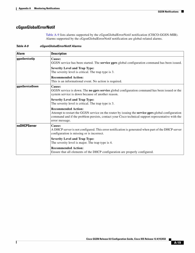
Appendix A Monitoring Notifications GGSN Notifications
cGgsnGlobalErrorNotif
Table A-9 lists alarms supported by the cGgsnGlobalErrorNotif notification (CISCO-GGSN-MIB). Alarms supported by the cGgsnGlobalErrorNotif notification are global-related alarms.
Table A-9 cGgsnGlobalErrorNotif Alarms
Alarm Description
ggsnServiceUp Cause: GGSN service has been started. The service gprs global configuration command has been issued.
Severity Level and Trap Type: The severity level is critical. The trap type is 3.
Recommended Action: This is an informational event. No action is required.
ggsnServiceDown Cause: GGSN service is down. The no gprs service global configuration command has been issued or the system service is down because of another reason.
Severity Level and Trap Type: The severity level is critical. The trap type is 3.
Recommended Action: Attempt to restart the GGSN service on the router by issuing the service gprs global configuration command and if the problem persists, contact your Cisco technical support representative with the error message.
noDHCPServer Cause: A DHCP server is not configured. This error notification is generated when part of the DHCP server configuration is missing or is incorrect.
Severity Level and Trap Type: The severity level is major. The trap type is 4.
Recommended Action: Ensure that all elements of the DHCP configuration are properly configured.
A-19Cisco GGSN Release 8.0 Configuration Guide, Cisco IOS Release 12.4(15)XQ3

Appendix A Monitoring Notifications GGSN Notifications
cGgsnAccessPointNameNotif
Table A-10 lists alarms supported by the cGgsnAccessPointNameNotif notification (CISCO-GGSN-MIB). Alarms supported by the cGgsnAccessPointNameNotif notification are APN-related alarms.
Table A-10 cGgsnAccessPointNameNotif Alarms
Alarm Description
noRadius Cause: A RADIUS server is not configured. This error notification is generated when part of the RADIUS server configuration is missing.
Severity Level and Trap Type: The severity level is major. The trap type is 4.
Recommended Actions:
1. Verify that the RADIUS server is properly configured and that you can ping it.
2. Ensure that the RADIUS server is configured properly.
Note The error message, issue a show running configuration and contact your Cisco technical support representative.
A-20Cisco GGSN Release 8.0 Configuration Guide, Cisco IOS Release 12.4(15)XQ3

Appendix A Monitoring Notifications GGSN Notifications
ipAllocationFail Cause: Dynamic IP allocation failed because of one of the following reasons:
1. One of the following DHCP or RADIUS server problem might have occurred:
a. The DHCP/RADIUS server IP address is configured incorrectly in the GGSN.
b. The DHCP/RADIUS server is reachable, but the configuration to allocate IP addresses might be incorrect.
c. The DHCP or RADIUS server is properly configured, but cannot be reached.
2. Dynamic IP allocation is disabled in the APN configuration.
3. The PAP or CHAP username and password information is missing from the RADIUS client in transparent mode. Therefore, this information is missing in the PDP activation request.
Severity Level and Trap Type: The severity level is major. The trap type is 4.
Recommended Actions:
1. Check the DHCP/RADIUS server configuration, ensuring that:
a. The DHCP/RADIUS server IP address configured on the GGSN is valid.
b. The DHCP/RADIUS server is properly configured to allocate IP addresses.
c. The DHCP/RADIUS server is reachable (via the ping command).
2. Configure IP allocation pool in the APN as either DHCP proxy client or RADIUS client.
3. If none of the above does not resolve the alarm condition, contact you Cisco technical support representative with the error message.
apnUnreachable Cause: A PDP activation has failed because the APN requested in the create PDP context request is not configured on the GGSN.
Severity Level and Trap Type: The severity level is major. The trap type is 4.
Recommended Action: Check the configuration of the corresponding APN. If the configuration appears to be correct, contact your Cisco technical support representative with the error message and saved output of the show running-config and show gprs access-point all commands.
Table A-10 cGgsnAccessPointNameNotif Alarms (continued)
Alarm Description
A-21Cisco GGSN Release 8.0 Configuration Guide, Cisco IOS Release 12.4(15)XQ3
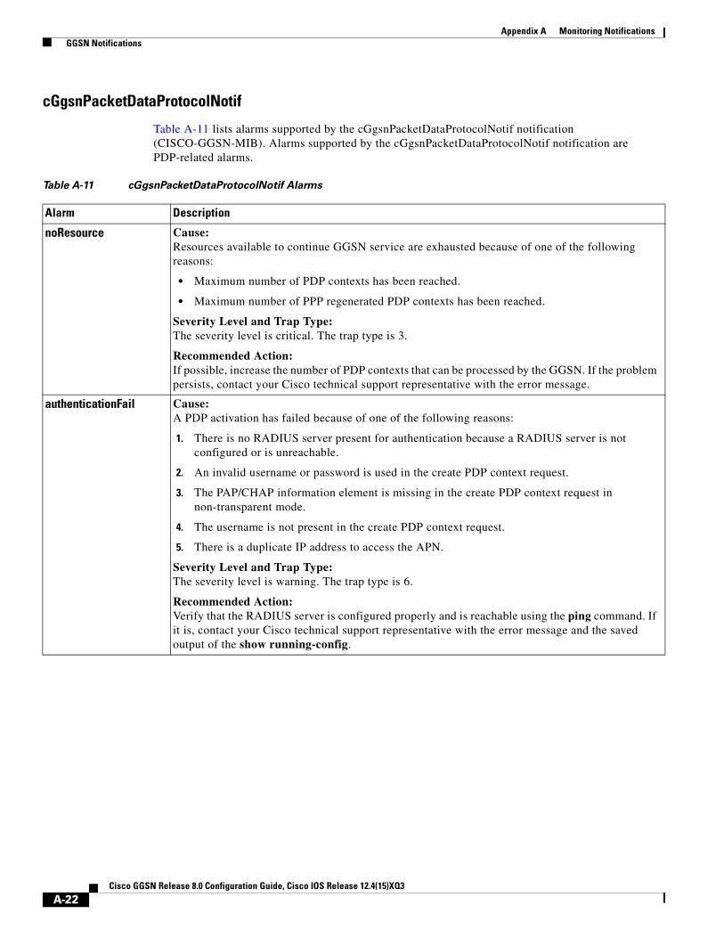
Appendix A Monitoring Notifications GGSN Notifications
cGgsnPacketDataProtocolNotif
Table A-11 lists alarms supported by the cGgsnPacketDataProtocolNotif notification (CISCO-GGSN-MIB). Alarms supported by the cGgsnPacketDataProtocolNotif notification are PDP-related alarms.
Table A-11 cGgsnPacketDataProtocolNotif Alarms
Alarm Description
noResource Cause: Resources available to continue GGSN service are exhausted because of one of the following reasons:
• Maximum number of PDP contexts has been reached.
• Maximum number of PPP regenerated PDP contexts has been reached.
Severity Level and Trap Type: The severity level is critical. The trap type is 3.
Recommended Action: If possible, increase the number of PDP contexts that can be processed by the GGSN. If the problem persists, contact your Cisco technical support representative with the error message.
authenticationFail Cause: A PDP activation has failed because of one of the following reasons:
1. There is no RADIUS server present for authentication because a RADIUS server is not configured or is unreachable.
2. An invalid username or password is used in the create PDP context request.
3. The PAP/CHAP information element is missing in the create PDP context request in non-transparent mode.
4. The username is not present in the create PDP context request.
5. There is a duplicate IP address to access the APN.
Severity Level and Trap Type: The severity level is warning. The trap type is 6.
Recommended Action: Verify that the RADIUS server is configured properly and is reachable using the ping command. If it is, contact your Cisco technical support representative with the error message and the saved output of the show running-config.
A-22Cisco GGSN Release 8.0 Configuration Guide, Cisco IOS Release 12.4(15)XQ3

Appendix A Monitoring Notifications GGSN Notifications
ccrInitFail Cause: The CCR(Initial) is sent to a Diameter server and the Tx time expired before receiving a CCA(Initial) response.
Severity Level and Trap Type: The severity level is major. The trap type is 4.
Recommended Action: The action on the PDP context creation is determined by the credit control failure handling (CCFH) configuration. Check the Diameter server and DCCA Tx timer and CCFH configurations on the GGSN to ensure they have been configured correctly.
quotaPushFail Cause: The quota push failed because: 1) the path between the CSG and quota server process on the GGSN is down, or 2) the CSG sent a negative Quota Push response for a Quota Push request.
Severity Level and Trap Type: The severity level is major. The trap type is 4.
Recommended Action: Check the CSG configuration, and the quota server configuration on the GGSN and the path state between the two. If the condition persists, contact your Cisco technical support representative with the error message.
Table A-11 cGgsnPacketDataProtocolNotif Alarms (continued)
Alarm Description
A-23Cisco GGSN Release 8.0 Configuration Guide, Cisco IOS Release 12.4(15)XQ3

Appendix A Monitoring Notifications GGSN Notifications
CgprsCgAlarmNotif
Table A-12 lists alarms supported by the CgprsCgAlarmNotif notification (CISCO-GPRS-CHARGING-MIB). Alarms supported by the CgprsCgAlarmNotif notification are alarms related to the charging functions of the GGSN.
Table A-12 CgprsCgAlarmNotif Alarms
Alarm Description
cgprsCgAlarmCgDown Cause: The charging gateway (primary, secondary, and tertiary) is down because it is not configured or there is a missing response to a nodealive request on the charging gateway path.
Severity Level and Trap Type: The severity level is critical. The trap type is 3.
Recommended Action: Verify that a charging gateway configuration exists and that the correct IP address is assigned. If it is, then the charging gateway is down.
cgprsCgAlarmCgUp Cause: The charging gateway is up.
Severity Level and Trap Type: The severity level is critical. The trap type is 3.
Recommended Action: This is an informational event. No action is required.
cgprsCgAlarmTransFailure Cause: The GGSN has repeatedly failed to receive a response from the charging gateway for data record transfer requests.
Severity Level and Trap Type: The severity level is critical. The trap type is 3.
Recommended Action: Verify that the charging gateways are properly configured on the GGSN and charging functionality is active.
cgprsCgAlarmTransSuccess Cause: The GGSN has successfully sent data record transfer requests to the charging gateway after the failure.
Severity Level and Trap Type: The severity level is critical. The trap type is 3.
Recommended Action: This is an informational event. No action is required.
cgprsCgAlarmCapacityFull Cause: The GGSN buffer is full and subsequent packets might be dropped.
Severity Level and Trap Type: The severity level is critical. The trap type is 3.
Recommended Action: Confirm the value configured for the gprs charging send-buffer global configuration command, and if possible, increase the number of bytes configured for the buffer.
A-24Cisco GGSN Release 8.0 Configuration Guide, Cisco IOS Release 12.4(15)XQ3

Appendix A Monitoring Notifications GGSN Notifications
cgprsCgAlarmCapacityFree Cause: The GGSN is able to buffer G-CDR after a failure to buffer G-CDRs has occurred.
Severity Level and Trap Type: The severity level is critical. The trap type is 3.
Recommended Action: This is an informational event. No action is required.
cgprsCgAlarmEchoFailure Cause: The GGSN has failed to receive an echo response from the charging gateway to an echo request.
Severity Level and Trap Type: The severity level is critical. The trap type is 3.
Recommended Action: Verify that the charging gateways are properly configured on the GGSN. If the condition persists, contact your Cisco technical support representative with the error message.
cgprsCgAlarmEchoRestored Cause: The GGSN has received an echo response from the charging gateway after an cgprsCgAlarmEchoFailure was sent.
Severity Level and Trap Type: The severity level is critical. The trap type is 3.
Recommended Action: This is an informational event. No action required.
cgprsCgAlarmChargingDisabled Cause: Indicates that charging transactions on the GGSN are disabled.
Severity Level and Trap Type: The severity level is critical. The trap type is 3.
Recommended Action: This is an informational event. No action is required.
cgprsCgAlarmChargingEnabled Cause: Indicates that charging transactions on the GGSN are enabled.
Severity Level and Trap Type: The severity level is critical. The trap type is 3.
Recommended Action: This is an informational event. No action is required.
cgprsCgGatewaySwitchoverNotif Cause: Indicates that the active charging gateway has switched.
Recommended Action: This is an informational event. Determine why the charging gateway switchover occurred.
Table A-12 CgprsCgAlarmNotif Alarms (continued)
Alarm Description
A-25Cisco GGSN Release 8.0 Configuration Guide, Cisco IOS Release 12.4(15)XQ3

Appendix A Monitoring Notifications GGSN Notifications
cgprsAccPtCfgNotif
Table A-13 lists alarms supported by the cgprsAccPtCfgNotif notification (CISCO-GPRS-ACC-PT-MIB).
cgprsCgInServiceModeNotif Cause: Indicates that the GGSN charging function has been placed in in-service/operational mode from maintenance mode.
Recommended Action: This is an informational event. No action is required.
cgprsCgMaintenanceModeNotif Cause: Indicates that the GGSN charging function has been placed in maintenance mode from in-service/operational mode.
Recommended Action: This is an informational event. No action is required.
Table A-12 CgprsCgAlarmNotif Alarms (continued)
Alarm Description
Table A-13 cgprsAccPtCfgNotif
Alarm Description
cgprsAccPtCfgNotif Cause: The access point configuration has been created, modified, or deleted.
Severity Level and Trap Type: Not applicable
Recommended Action: This is an informational event. No action is required.
A-26Cisco GGSN Release 8.0 Configuration Guide, Cisco IOS Release 12.4(15)XQ3