cisco ccnp certification courseware · static route routing issues •need a route to connect over...
TRANSCRIPT


1
IMPLEMENTING TELEWORKER SERVICES
Teleworker Connectivity
• Branch offices and teleworkers can connect via cable modems or DSL
• Both utilize PPP to provide authentication and accounting ability since neither is native to Ethernet/ATM
– Cable modems
• Governed by Data over Cable Service Interface Specification (DOCSIS)
• Uses PPPoE
– DSL
• Uses PPPoA

2
IPSEC
IPSEC
• IPSEC
– Supports IP traffic only
– Traditionally supports unicast traffic only
– Provides security by offering authentication and encryption
– Can be used in the following VPN configuration
• DMVPN (Dynamic Multipoint Virtual Private Network)
• Virtual Tunnel interfaces (VTI)
• GET (Group Encrypted Transport)

3
What is IPSec?
• A IP Security framework that includes multiple protocols and algorithms
• Provides for:
–Authentication of every IP packet
–Verification of data integrity for each packet
–Confidentiality of packet payload
–Anti-replay protection to verify each packet is unique
IPSec Components
• Security Protocols
–Authentication Header (AH)
–Encapsulating Security Payload (ESP)
• Key Management
–ISAKMP, IKE, SKEME
• Security Algorithms
–DES, 3DES, AES

4
IPSec Security Protocols
• Encapsulating Security Payload (ESP)
–IP Protocol 50
–Provides confidentiality, integrity, origin authentication, and anti-replay
• Authentication Header (AH)
–IP Protocol 51
–Provides integrity, origin authentication, and anti-replay
• Security protocols can operate in tunnel mode or transport mode
Transport Mode
Data L4 Hdr Original IP HDr
Data L4 Hdr Original IP HDr
AH
Authenticated
Data L4 Hdr Original IP HDr
Original
AH
ESP ESP ESP
Trailer ESP
Auth.
Authenticated
Encrypted

5
Tunnel Mode
Data L4 Hdr Original IP HDr
Original
Data L4 Hdr AH
ESP
AH Original IP HDr
Data L4 Hdr New
IP HDr ESP
Original IP HDr
ESP Trailer
ESP Auth.
Authenticated
Authenticated
Encrypted
New IP HDr
Implementing IPSec VPNs
IKE Policies
IPSec Transform Sets
Crypto ACL

6
Implementing IPSec VPNs
1. Establish ISAKMP policy
2. Configure IPSec transform set
3. Configure crypto ACL
4. Configure crypto map
5. Apply crypto map to interface
1. Establish ISAKMP policy
Crypto isakmp policy 1
authentication pre-shared
hash sha
encryption aes 128
group 2
!
Crypto isakmp key SECRET address 172.16.0.2
A B E1 172.16.0.1 E1 172.16.0.2 E0 10.1.0.0/16 E0 10.2.0.0/16
Crypto isakmp policy 5 authentication pre-shared hash sha encryption aes 128 group 2 ! Crypto isakmp key SECRET address 172.16.0.1
7
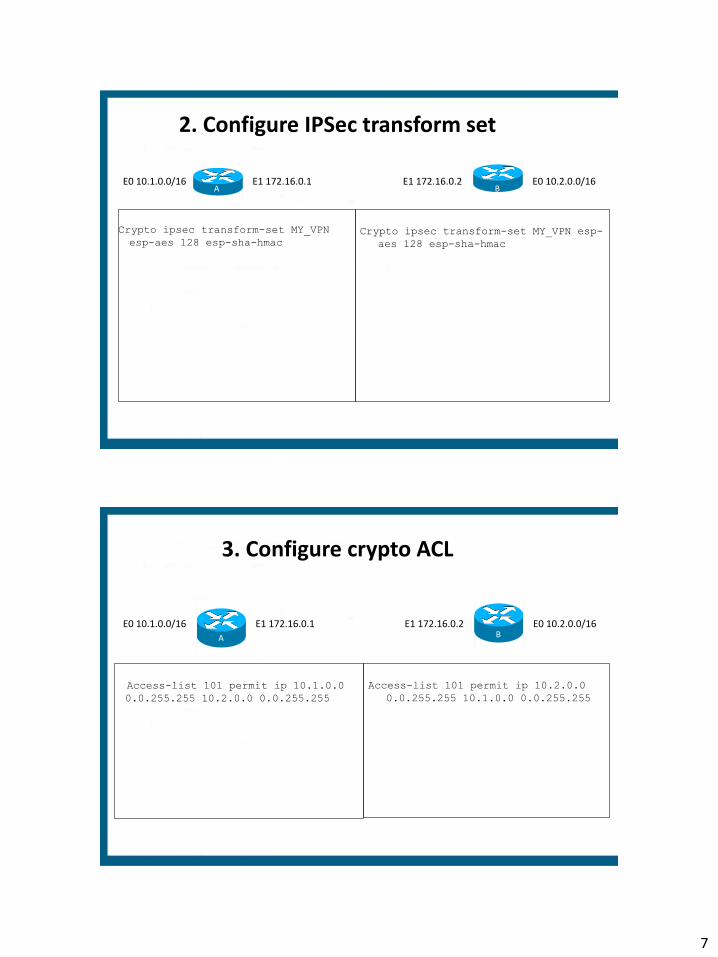
2. Configure IPSec transform set
Crypto ipsec transform-set MY_VPN
esp-aes 128 esp-sha-hmac
Crypto ipsec transform-set MY_VPN esp-
aes 128 esp-sha-hmac
A B E1 172.16.0.1 E1 172.16.0.2 E0 10.1.0.0/16 E0 10.2.0.0/16
3. Configure crypto ACL
Access-list 101 permit ip 10.1.0.0
0.0.255.255 10.2.0.0 0.0.255.255
Access-list 101 permit ip 10.2.0.0
0.0.255.255 10.1.0.0 0.0.255.255
A
B E1 172.16.0.1 E1 172.16.0.2 E0 10.1.0.0/16 E0 10.2.0.0/16

8
4. Configure crypto map
Crypto map VPN_TO_ROUTERB 10 ipsec-
isakmp
set peer 172.16.0.2
match address 101
set transform-set MY_VPN
Crypto map VPN_TO_ROUTERA 10 ipsec-
isakmp
set peer 172.16.0.1
match address 101
set transform-set MY_VPN
A B
E1 172.16.0.1 E1 172.16.0.2 E0 10.1.0.0/16 E0 10.2.0.0/16
5. Apply crypto map to interface
Interface ethernet 1
ip address 172.16.0.1 255.255.0.0
crypto map VPN_TO_ROUTERB
!
Ip route 10.2.0.0 255.255.0.0
172.16.0.2
Interface ethernet 1
ip address 172.16.0.2 255.255.0.0
crypto map VPN_TO_ROUTERA
!
Ip route 10.1.0.0 255.255.0.0
172.16.0.1
A
B E1 172.16.0.1 E1 172.16.0.2 E0 10.1.0.0/16 E0 10.2.0.0/16

9
GRE VPNS
GRE and GRE over IPSEC
WHY GRE?
• GRE can encapsulate and tunnel any protocol, IPSEC is limited to IP
• GRE can encapsulate unicast, multicast, and broadcast traffic, IPSEC is traditionally limited to just unicast
• Hence GRE can be used to tunnel dynamic routing protocols
• Major weakness within GRE: extremely limited security

10
GRE Tunnels
Data L4 Hdr Original IP HDr
Original
Data L4 Hdr Original IP HDr
GRE IP Hdr GRE
Routing over GRE tunnel
Interface tunnel 0
ip address 192.168.5.5 255.255.255.252
tunnel source serial 0/0
tunnel destination 172.17.0.1
tunnel mode gre ip
!
Router eigrp 1
network 192.168.5.4 0.0.0.3
network 192.168.1.0 0.0.0.255
!
Ip route 0.0.0.0 0.0.0.0 172.16.0.254
Interface tunnel 1
ip address 192.168.5.6 255.255.255.252
tunnel source serial 0/0
tunnel destination 172.16.0.1
tunnel mode gre ip
!
Router eigrp 1
network 192.168.5.4 0.0.0.3
network 192.168.2.0 0.0.0.255
!
Ip route 0.0.0.0 0.0.0.0 172.17.0.254
B
s0/0 172.16.0.1
s0/0 172.17.0.1 A
Fa0/0 192.168.1.1
Fa0/0 192.168.2.1

11
Routing over GRE
Tunneling issues:
• Tunnel interface numbers do not have to match
• The tunnel source must be a local interface that is reachable over the WAN connection
• The tunnel destination must be an address of the remote router that is reachable over the WAN
• The tunnel interfaces must be on the same network to form neighborship
Static Route
Routing issues
• Need a route to connect over the WAN/internet
–Ip route 0.0.0.0 0.0.0.0 <next-hop ip> !Not remote tunnel endpoint!
• EIGRP neighbor commands are unnecessary because GRE will convert the EIGRP multicast traffic to unicast
• EIGRP autonomous system numbers must match
• EIGRP network statements must enable directly connected networks
–LAN interface
–Tunnel interface
–NOT the WAN interface as it is connected to the internet

12
GRE Over IPSec
• Commonly used on Internet
• Emulates WAN to provide hub-and-spoke topology
Data L4 Hdr IP HDr GRE IP Hdr ESP IP Hdr Tunnel ESP Trailer
Data L4 Hdr IP HDr GRE ESP IP Hdr Transport ESP Trailer
GRE over IPSEC
• GRE configuration requires
–Tunnel source
–Tunnel destination
–Tunnel IP address
• IPSEC configuration requires a crypto map
–The crypto ACL must reference GRE traffic instead of the LAN traffic

13
GRE over IPSEC configuration
Access-list 110 permit gre host 10.10.0.1 host 10.20.0.1
Crypto map VPN 10 ipsec-isakmp
set peer 10.20.0.1
set transform-set BRANCH_VPN
match address 110
Interface tunnel 0
ip address 192.168.0.1 255.255.255.0
tunnel source serial 0/0
tunnel destination 10.20.0.1
crypto map VPN
interface serial 0/0
ip address 10.10.0.1 255.255.255.0
crypto map VPN
•Crypto map name must match, case sensitive •ACL must reference GRE traffic from one tunnel endpoint to the other and be referenced within the crypto map
Implement IPv6 Routing

14
IPv6 TOPICS
• Comparison with IPv4
• Addressing
• Address Assignment
• Routing
• Transition Methods
IPv4 versus IPv6
How IPv6 is better

15
IPv6 Enhancements
• No more broadcasts • Built-in in support for anycast addresses • IP mobility is built-in • IPSEC is mandatory
– Routing protocols no longer have any authentication methods as they rely on IPv6 IPSEC
• Number of Addresses – In IPv4 address depletion and routing table size are major
concerns. In IPv6 these concerns are alleviated: • 128 bit totaling approximately 3.4x 10^38 • Route summarization much more effective • Furthermore there is no need for NAT/PAT
IPv6 Header Enhancements
• Header length fixed at 40 bytes, IPv4 header 20 bytes
• No more L3 Checksum
– Simpler and more efficient than IPv4 despite increased size
• Next Header field – specifies the next encapsulated protocol
• Flow label– to improve QOS and monitoring

16
IPv6 Addressing
Rules and Examples
Addressing
• All addresses are 128 bits
• CIDR notation used to denote subnet mask
• Write as sequence of eight sets of four hex digits (16 bits each) separated by colons
• Can be written shorthand:
– Lead zeros in a quartet may be omitted
– Contiguous all-zero groups may be replaced by “::” but only one such group can be replaced

17
IPv6 Addressing Example
• 3ffe:3700:0200:00ff:0000:0000:0000:0001
can be written:
• 3ffe:3700:200:ff:0:0:0:1
or:
• 3ffe:3700:200:ff::1
IPv6 Address Types
• IPv6 defines three types of addresses or scopes:
– Unicast
• Global: public addresses
• Link local: not routable; used for router and neighbor discovery
• Unique local: equivalent of RFC 1918 addresses (site local addresses have been deprecated); uses FD00::/8
– Anycast— Address specifies a set of hosts/servers for a given organization's application. A packet sent to an anycast address is delivered to one of the hosts identified by that address, usually the closest one as defined by the routing protocol.
• All nodes should provide uniform service
• Suitable for load-balancing and content-delivery services
• (config-if)#ipv6 address <address> anycast
– Multicast— Same concept as IPv4 multicast.
18
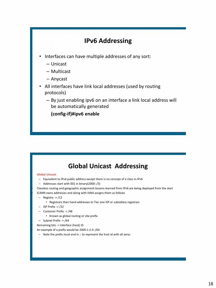
IPv6 Addressing
• Interfaces can have multiple addresses of any sort:
– Unicast
– Multicast
– Anycast
• All interfaces have link local addresses (used by routing protocols)
– By just enabling ipv6 on an interface a link local address will be automatically generated
(config-if)#ipv6 enable
Global Unicast Addressing • Global Unicast
– Equivalent to IPv4 public address except there is no concept of a class in IPv6
– Addresses start with 001 in binary(2000::/3)
• Classless routing and geographic assignment lessons learned from IPv6 are being deployed from the start
• ICANN owns addresses and along with IANA assigns them as follows
– Registry -> /12
• Registrars then hand addresses to Tier one ISP or subsidiary registrars
– ISP Prefix -> /32
– Customer Prefix -> /48
• Known as global routing or site prefix
– Subnet Prefix -> /64
• Remaining bits -> Interface (host) ID
• An example of a prefix would be 2000:1:2:3::/64
– Note the prefix must end in :: to represent the host id with all zeros

19
Link-Local (unicast) Addresses
• Link-Local Unicast
– No real equivalent in IPv4
– Start with FE80::/10
– Used by routing protocols, neighbor discovery, and router discovery
– Also used to denote next-hop addresses within the IPv6 routing table
– Can be automatically created using EUI-64 variants or manually specified
• (config-if)#ipv6 address <address> link-local
Multicasting
• Multicast
– FF00::/8
– FF02::/16 link local addresses, for example
• FF02::1 all hosts
• FF02::2 all routers in a local segment
• FF02::5 ALL OSPF router
• FF02::6 DR and BDR
• FF02::9 RIPng
• FF02::A EIGRP
• FF02::1:2 unknown DHCP servers (dhcp relay agent function)

20
Other Notable IPv6 Addresses
• ::/0 is the notation for a default route
– (config)#ipv6 route ::/0 s0/0/0
• ::1/128 is the loopback address
– Equivalent of 127.0.0.1
• ::/128 is the notation for an unspecified route or address
Address Assignment

21
IPv6 Address Assignment
• Hosts can be configured with an IP address via 3 methods
– Static or manual addressing
– DHCPv6
• Stateful, roughly the same as DHCPv4
• Does not assign default gateway addresses however
• (config-if)#ipv6 address dhcp
– Stateless Autoconfiguration
– No equivalent in IPv4
– No need for stateful DHCP
– Uses EUI-64 to generate host address
– Uses stateless DHCP to acquire DNS information
Static or Manual addressing
(config-if)#ipv6 address address/prefix-length [eui-64]
• EUI-64: automatically configure a host address
(config-if)#ipv6 address 3FFE:2E::/64 eui-64
OR
(config-if)#ipv6 address 2001:2:3::1/64
OR
(config-if)#ipv6 enable

22
EUI-64
• Used to automatically generate a unique host (interface) ID
• 48 bit MAC address is split and FF-FE is added in the middle to make up 64 bit host address
• 7th bit of first octet is set to 1 to specify the address as unique (Group/Local bit)
• For example the MAC address 005C:99D0:CF34 becomes 025C:99FF:FED0:CF34 for the host portion of an IPv6 address
Stateless Auto-configuration
• Part of Neighbor Discovery Protocol (ICMP) • Multicast traffic including
– Router Solicitation (RS) messages • Source address is link-local unicast, destination address is FF02::2 • From host to all routers • Host sends message to acquire the IP address of its router • To configure cisco device as a host using stateless autoconfig
– (config)#ipv6 address autoconfig – Router Advertisement (RA) messages
• Source address is link-local unicast, destination address is FF02::1 • From router to all hosts • The router advertises its address along with one or more prefix • #show ipv6 router shows cached RA messages

23
Stateless Autoconfiguration
• Routers send Router Advertisement (RA) messages that may include:
– Whether nodes could use address auto-configuration
– One or more on-link IPv6 prefixes that nodes on the local link could use
– Lifetime information for each prefix
– Whether the router sending the advertisement should be used as a default router
– Additional information for hosts, such as the hop limit and MTU a host should use
ICMP: Neighbor Discovery
• Address Resolution Protocol was used to resolve IP address to MAC addresses
• ARP was broadcast based and no longer exists in IPv6
• Effectively replaced by Neighbor Discovery protocol
• #Show ipv6 neighbors shows NDP cache
• PCs send out Neighbor Solicitation (NS) messages to resolve MAC addresses and listen for Neighbor Advertisements (NA) as a response
• Uses solicited node multicast addresses
– FF02::1:FF:0/104
• Last 24 bits based on IPv6 address
– MAC address: 01005e followed by the last 23 bits of IPv6 address

24
DAD and Inverse NDP
Duplicate Address Detection
– NS message with one’s own solicited multicast address
– If response received then there is a duplicate address
Inverse Neighbor Discovery
– Replaces inverse ARP in Frame-relay networks
– Uses inverse NS and inverse NA messages
Routing
Static routes, dynamic routing protocols and redistribution

25
IPv6 Routing
• Static
• RIPng
• OSPFv3
• EIGRP for IPv6
• MP-BGP4
• IS-IS for IPv6
IPv6 Routing enabled with
(config)#ipv6 unicast-routing
Routing Protocols
• No more network commands, all protocols enabled on a per-interface level
• No native authentication methods, all protocols use IPv6 ESP/AH (IPv6 IPSEC)
• Neighbors do not have to be on the same subnet in EIGRP and OSPFv3
• Routing table shows Local (L) routes with /128 masks to represent host addresses
– #show ipv6 route
• Redistribution
– Host routes (L for local) are not redistributed
– Seed metric for RIPng=source IGP metric
– No subnets keyword for OSPFv3 as there is no classful concepts in IPv6
– Directly connected networks are not automatically redistributed
• Redistribute command must have the keyword include-connected

26
Static Routing
• (config)#ipv6 route <prefix/mask> <next-hop IP address>
• (config)#ipv6 route ::/0 2000:1:2::1
• Can use any valid next-hop IP address
• If link-local address is used for the next-hop address then you must configure the exit interface and link-local address
– (config)#ipv6 route 2003:12::/64 s0/0/0 FE80:1::1
RIPng
• Essentially the same as RIPv2
• Globally enable RIPng process
– (config)#ipv6 router rip <name> enable
• Enable individual interfaces to run RIPng
– (config-if)#ipv6 rip <name>
• Link local and host routes not advertised
• Seed metric into RIPng for redistribution is based on the source IGP metric

27
Differences between OSPF v2 and v3
• Multiple OSPF instances can run over a single link
– Cannot select specific interface addresses via ACLs or any other method into a given OSPF process.
• Uses link-local addresses to find adjacent neighbors
• 224.0.0.5 is now FF02::5
• 224.0.0.6 is now FF02::6
Differences between OSPF v2 and v3 (cont.)
• New LSA types
– Link LSAs (type 8): link-local flooding
– Intra-area prefix (type 9): generated by ABR and sent to backbone

28
OSPFv3 Configuration
1. Enable IPv6 routing
(config)#ipv6 unicast-routing
2. Enter Router Configuration mode
(config)#ipv6 router ospf 1
3. Assign 32-bit Router ID
(config-router)#router-id 1.1.1.1
OSPFv3 Configuration
4. Enable OSPF process on a per interface basis
(config)#interface ethernet 0
(config-if)#ipv6 ospf 1 area 0
(config)#interface serial 0
(config-if)#ipv6 ospf 1 area 1

29
OSPFv3 Configuration
5. (optional) Configure parameters on the interface
(config-if)#ipv6 ospf priority 255
(config-if)#ipv6 ospf cost 20
6. (optional) Configure summarization
(config)#ipv6 router ospf 1
(config-router)#area 1 range 2001:0DB8::/48
OSPFv3 Example
E0 2001:F8C:32::1/64 E1 2001:F8C:33::1/64
Area 0 Area 1
ipv6 unicast-routing
!
interface ethernet 0
ipv6 address 2001:F8C:32::1/64
ipv6 ospf 1 area 0
ipv6 ospf 1 priority 0
!
interface ethernet 1
ipv6 address 2001:F8C:33::1/64
ipv6 ospf 1 area 1
!
ipv6 router ospf 1
router-id 1.1.1.1

30
Verifying OSPFv3 Router#show ipv6 ospf interface FastEthernet0/0 is up, line protocol is up Link Local Address FE80::205:5FFF:FED3:5808, Interface ID 3 Area 1, Process ID 1, Instance ID 0, Router ID 172.16.3.3 Network Type BROADCAST, Cost: 1 Transmit Delay is 1 sec, State BDR, Priority 1 Designated Router (ID) 172.16.6.6, local address FE80::205:5FFF:FED3:6408 Backup Designated router (ID) 172.16.3.3, local address FE80::205:5FFF:FED3:5808 Timer intervals configured, Hello 10, Dead 40, Wait 40, Retransmit 5 Hello due in 00:00:05 Index 1/1/1, flood queue length 0 Next 0x0(0)/0x0(0)/0x0(0) Last flood scan length is 12, maximum is 12 Last flood scan time is 0 msec, maximum is 0 msec Neighbor Count is 1, Adjacent neighbor count is 1 Adjacent with neighbor 172.16.6.6 (Designated Router) Suppress hello for 0 neighbor(s)
Troubleshooting OSPFv3
• Clear ipv6 ospf process
– Re-establishes adjacencies
– repopulates the OSPF database
– runs the shortest path first (SPF) algorithm

31
EIGRP
• Also uses router-id
• Also does not advertise link local or host routes
• Neighbors do not have to be on the same subnet
• Shutdown by default, need to issue the no shutdown command
– This command exists for OSPFv3 as well but OSPFv3 is enabled by default
Transition Methods
Coexistence with IPv4 networks
Dual-stack, Tunneling, and NAT-PT

32
Transition Approaches 1. Dual Stack
-systems configured with IPv4 and IPv6 addresses -IPv4 and IPv6 routing protocols can be run simultaneously
2. NAT-PT • Translate the entire IPv4 header to IPv6 and vice versa • Can utilize DNS as application layer gateway • Deprecated
3. Tunneling • IPv6 packets encapsulated within IPv4 • Configured between dual-stack routers or hosts • 5 types of tunnels
• Manually Configured Tunnels (MCT) • GRE • 6to4 tunnels • ISATAP • IPv4 compatible tunnels (deprecated)
Tunneling
• Less configuration of IPv6 as compared to dual-stack but more overhead due to tunneling.
• Two categories of tunneling
– Point to point (static)
• GRE
• Manually Configured Tunnels (MCT)
– Multipoint (automatic)
• 6to4
• ISATAP

33
Tunneling
• Point to point – Configure tunnel source and destination – Support dynamic routing protocols – Good if there is frequent usage as there is less work per packet
• Multipoint
– Configure only tunnel source – Dynamically learns tunnel destination based on destination IPv6
address or IPv6 next-hop address – More addressing rules – IPv4 address embedded into IPv6 address – Do not support routing protocols, therefore need static routes
Tunneling – 6to4 tunnels
• IPv4 protocol 41
• Each site receives a /48 prefix comprised of
– 2002::/16 (address range specifically assigned to 6to4)
– Followed by IPv4 address
» Use the IPv4 address specified as the tunnel source
• Automatic, allows for multiple destinations
• Used for the Internet
– Manual tunneling
• IPv4 protocol 41

34
Configuring IPv6 Tunnels: Manual
A B
IPv6 IPv6
IPv4
IPv4: 192.168.1.1/24
IPv6:2001:16F9::1/64 IPv4: 192.168.200.88/24
IPv6:2001:16F9::2/64 interface tunnel 0
ipv6 address 2001:16F9::1/64
tunnel source 192.168.1.1
tunnel destination 192.168.200.88
tunnel mode ipv6ip
interface tunnel 0
ipv6 address 2001:16F9::2/64
tunnel source 192.168.200.88
tunnel destination 192.168.1.1
tunnel mode ipv6ip
Configuring IPv6 Tunnels: GRE
A B
IPv6 IPv6
IPv4
IPv4: 192.168.1.1/24
IPv6:2001:16F9::1/64 IPv4: 192.168.200.88/24
IPv6:2001:16F9::2/64 interface tunnel 0
ipv6 address 2001:16F9::1/64
tunnel source 192.168.1.1
tunnel destination 192.168.200.88
interface tunnel 0
ipv6 address 2001:16F9::2/64
tunnel source 192.168.200.88
tunnel destination 192.168.1.1
tunnel mode gre ip

35
Configuring 6to4 Tunnels
• Point-to-multipoint model (multiple destinations)
• Destination is determined by extracting IPv4 address from IPv6 address
– IPv4 address is converted to hex
– Start with 2002::/16
– /48 bit prefix with 2nd and 3rd quartet derived from IPv4 address of tunnel source
interface tunnel 0
ipv6 address 2002:C0A8:6301::1/64
tunnel source ethernet 0
tunnel mode ipv6ip 6to4
interface ethernet 0
ip address 192.168.99.1 255.255.255.0
192.168.99.1 = C0A8:6301

1
1
TShoot
642-832
135 Minutes
790 pass
2
Exam Details
• 3 multiple choice questions to start with • Upon completing them there are 12 trouble tickets to resolve based on the
same topology • Each of the trouble tickets follows the same format in terms of questions
1. What device has the problem? 2. What technology is the problem related to?
– The answer for the first question changes the answers for this question 3. What command/concept would resolve the problem?
– The answer for the 2nd question change the answers for this question – Once a trouble ticket is completed you cannot come back to it, however
you can abort a trouble ticket and try a different one. – In other words you can do the 12 trouble tickets in any order

2
3
Exam details
– Take a look at the following link
– www.cisco.com/web/learning/le3/le2/le37/le10/tshoot_demo.html
– Once a trouble ticket is completed you cannot come back to it, however you can abort a trouble ticket and try a different one.
– In other words you can do the 12 trouble tickets in any order
4
Network Maintenance Models
• FCAPS: 5 stage ISO standard
• ITIL: IT Infrastructure Library-defines a collection of best practice recommendations
• TMN: Telecommunications Management Network, a ITU-T variation of FCAPS
• PPDIOO: Cisco lifecycle services maintenance model

3
5
FCAPS
• Is a network management strategy
• FCAPS stands for
• Fault
• Configuration
• Accounting
• Performance
• Security
6
FCAPS
• Fault: Network problems or faults are found and fixed.
• Configuration: The network is monitored and controlled. This includes keeping track of hardware and software on the network and any modifications to them.
• Accounting: Network resources are distributed and used equitably; end users and departments are charged for their network use.
• Performance: Network congestion and bottlenecks are minimized.
• Security: Only the people who really need access to specific network resources are allowed to use them - this applies equally to outside hackers and internal users
4
7
NTP
• Network Time Protocol
• Uses UDP port 123
• Used to synchronize time
• If you have multiple NTP servers then the NTP protocol itself figures out the most reliable time source
8
Logging
%LINK-3-UPDOWN: Interface Loopback7, changed state to up
%LINEPROTO-5-UPDOWN: Line protocol on Interface Loopback7
• What is the name for level 3 logging?
• What is the name for level 5 logging?
• What would the command logging console warning do?
• What is the command to log to a buffer? To a syslog server?

5
9
Management
EEM, IP SLA CLI Management
NTP
SDM, CNA GUI Management
TFTP, SCP backups
SYSLOG
10
Management Terms
• NTP=Network Time Protocol
• Syslog=a logging protocol
• TFTP=Trivial File Transfer Protocol
• IP SLA=IP Service Level Agreement
• GUI= graphical user interface
• CLI=Command-line interface

6
11
Management Terms
• CNA=Cisco Network Assistant
– A GUI used to manage multiple devices
• SCP=Secure Copy Protocol
• EEM=Embedded Event Manager
– Used for event detection, can be CLI or TCL script based
• SDM=Security Device Manager
– A GUI for Cisco Routers
12
PPDIOO
• Cisco network lifecycle – Prepare
• Develop Strategies for new developments – Plan
• Develop Network requirements – Design
• Develop Design documents – Implement
• Implement, Configure, Verify – Operate
• Maintain network health – Optimize
• Proactively manage and fine tune

7
13
Troubleshooting Methods
• Top-down
• Bottom-up
• Divide and Conquer
• Follow the traffic path
• Comparing Configurations
• Component swapping
Technology Review

8
DHCP
• DHCP provides IP addresses, subnet masks, default gateway information, etc.
• DHCP traffic flow (DORA)
– Discover—Broadcast from client to server
– Offer—Server to client
– Request—Client to server
– Acknowledgement—Server to client
• DHCP requests are broadcasts
– Routers do not forward broadcasts by default
– Routers can act as DHCP servers, clients, or forward on DHCP requests as unicasts
DHCP Server Configuration
Router(config)#ip dhcp pool pool-name
Router(config-dhcp)#network network [mask | prefix-length]
Router(config-dhcp)#default-router address
Router(config)#ip dhcp excluded-address address
Router(config)#ip dhcp excluded-address start-address end-address

9
DHCP Server Example ip dhcp excluded-address 192.168.1.10 192.168.1.19
ip dhcp pool BRANCHOFFICE
network 192.168.1.0/24
domain-name branchoffice.com
dns-server 192.168.1.18 192.168.1.19
option 150 ip 192.168.1.17
default-router 192.168.1.10
lease 30
ip dhcp excluded-address 172.16.0.1 172.0.10
!
ip dhcp pool CORPORATE
network 172.16.0.0 255.255.0.0
domain-name corporate.com
dns-server 172.16.0.2
!
interface fastethernet0/0
ip address 172.16.0.1 255.255.0.0
!
interface fastethernet0/1
ip address 172.17.0.1 255.255.0.0
--Create multiple pools for multiple subnets
DHCP Server Example

10
IP Helper
• Routers block broadcasts
• DHCP requests are broadcast
• IP helper takes broadcasts and converts them to unicast
DHCP Client DHCP Server
Broadcast request Unicast request
ip helper-address 10.0.0.10
10.0.0.10
(config-if)#ip helper-address <A.B.C.D>
On the closest interface (SVI or routed) to the PC
NAT
Router(config)#interface ethernet 0/0
Router(config-if)#ip address 10.10.10.10 255.255.255.252
Router(config-if)#ip nat inside
Router(config)#interface serial 0/0/0
Router(config-if)#ip address 200.200.200.201 255.255.255.252
Router(config-if)#ip nat outside
Router(config)#access-list 1 permit 10.0.0.0 0.255.255.255
Router(config)#ip nat inside source list 1 interface s0/0/0 overload
Key points: •IP NAT inside command must be issued on the internal interface •IP NAT outside must be issued on the external interface •The ACL must reference all internal IP addresses •Keyword overload allows the public address to be reused

11
Routing Review
• BGP – Neighbourship – Redistribution
• OSPF
– Neighbourship – Redistribution
• Route-maps
• EIGRP – Redistribution
• Route-maps – Neighbourship
Switching Review
• VLANs
• Trunks
• Etherchannels
• HSRP
– Tracking
– Elections
12
Miscellaneous Review
• DHCP
– Server
– IP Helper Address
• Vlan Access-map
– ACL
• NAT
– ACL
Game Plan
• Follow a strategy
• If you get lost stop running random commands and focus on your game plan
• If you get lost and frustrated to the point of losing control of the exam, abort the trouble ticket and start fresh with another scenario.

13
Game Plan
• Where would you start?
– IPconfig on the PC
• IF there is no IP address?
– Correct Vlan assignment
– Functional trunk
– DHCP helper address
– DHCP server
Game Plan
• Where would you start?
– IPconfig on the PC
• IF there is an IP address?
– Ping the default gateway
» If you can’t then the problem is between you and the default gateway

14
Game Plan
• Where would you start?
– IPconfig on the PC
• IF there is an IP address?
– Ping the default gateway
» If you can then go to DSW1
» run show ip route
» Do you have a route to the outside world?
» If not then the problem is most likely?
Game Plan
• Where would you start?
– IPconfig on the PC
• IF there is an IP address?
– Ping the default gateway
» If you can then go to DSW1
» run show ip route
» Do you have a route to the outside world?
» If so then you should be able to get out of the LAN
» So what would you do?

15
False Logic or Sound logic?
• Scenario 1
– PC1 has no IP address
– R4 is the DHCP server with an IP address of 10.2.2.1
– DSW1 has a ip helper-address of 10.99.99.1 for vlan X
– Fix the helper address?
• Scenario 2
– PC1 can ping its default-gateway (DSW1)
– DSW1 can ping R4
– Is the problem is between Router 4 and R1?

1
SWITCH
REVIEW SCENARIOS
VLAN
Choose 4 steps in creating a VLAN implementation plan:
References to design documents
Rollback guidelines
Detailed step by step Implementation
Time to perform steps
VTP assignments

2
VLAN
• Choose 4 steps in a VLAN-based verification plan
– Verify whether switchports have been pruned
– Verify whether vlans have been created
– Verify that there is inter-switch communication
– Verify creation of virtual interfaces
– Verify which ports are configured as promiscuous
– Verify vlan assignments on ports
VLAN: Network Requirements
• CHOOSE 4:
– Number of subnets
– Trunk/VTP assignments
– VLAN to IP mappings
– VLAN port assignments
– Location of each VLAN
– End to end dynamic trunk assignments

3
Baseline QOS Model
Prioritize the following traffic:
1. Interactive Video
2. Voice
3. Call signaling
4. Routing Protocols
5. Network Management
6. Streaming Video
Fill in the Blanks
MANAGEMENT NETWORK SYSTEM
IP SLA
RSTP
Dual-Power Supplies
NSF
SSO
NTP

4
7
Fa0/8-9 VLAN 20
HR Fa0/10-11 VLAN 21
SALES Fa0/12-13 VLAN 22 MGMT
Fa0/3 Fa0/3
Fa0/4 Fa0/4 SWA SWB
Set up trunking between SWA and SWB
using Fa0/3 – 4. Ensure that all vlans
including vlan 1 are tagged. Furthermore
use an open standard aggregation protocol
to configure these switches while ensuring
SWB is in control of the negotiation. Allow
traffic only from these vlans across the
trunk.
Make sure SWB is the root bridge for all
vlans.
On SWA configure an IP address of
192.168.5.25/24 for management. Also
configure the VLANs 20, 21, and 22 on
SWA. Add the ports designated by the
topology map to the respective VLANs
allow them to skip the STP delays.
Configuration Exercise 1
8
Fa0/8-9 VLAN 20
Fa0/10-11 VLAN 21
Fa0/12-13 VLAN 22
Fa0/3 Fa0/3
Fa0/4 Fa0/4 SWA SWB
SWA CONT’D: (config)#interface po1
(config-if)#no shutdown
(config-if)#interface range fa0/3 – 4
(config-range-if)#channel-group 1 mode passive
(config-range-if)#no shutdown
(config-range-if)#interface po1
(config-if)#switchport trunk encap dot1q
(config-if)#switchport mode trunk
(config-if)#switchport trunk native vlan 99
(config-if)#switchport trunk allowed vlan 1,20,21,22
(config-if)#interface vlan 1
(config-if)#ip address 192.168.5.25 255.255.255.0
(config-if)#no shutdown
Show vlan to verify vlans and port assignments
Show int vlan1 to verify ip address
Show interface trunk and show etherchannel summary
to verify trunks and port-channels after completing SWB.
Show run
SWA CONFIGURATION: (config)#vlan 20
(config-vlan)#name HR
(config-vlan)# vlan 21
(config-vlan)#name SALES
(config-vlan)#vlan 22
(config-vlan)#name MGMT
(config-vlan)#vlan 99
(config-vlan)#interface range fa0/8 – 9
(config-range-if)#switchport mode access
(config-range-if)#spanning-tree portfast
(config-range-if)#switchport access vlan 20
(config-range-if)#interface range fa0/10 – 11
(config-range-if)#switchport mode access
(config-range-if)#spanning-tree portfast
(config-range-if)#switchport access vlan 21
(config-range-if)#interface range fa0/12 – 13
(config-range-if)#switchport mode access
(config-range-if)#spanning-tree portfast
(config-range-if)#switchport access vlan 22
SOLUTION CONTINUED

5
9
Fa0/8-9 VLAN 20
Fa0/10-11 VLAN 21
Fa0/12-13 VLAN 22
Fa0/3 Fa0/3
Fa0/4 Fa0/4 SWA SWB
SWB CONFIGURATION:
! Show vlan to verify 99 is native vlan and fa0/3 – 4 are not assigned
to a vlan
(config)#vlan 20
(config-vlan)#name HR
(config-vlan)# vlan 21
(config-vlan)#name SALES
(config-vlan)#vlan 22
(config-vlan)#name MGMT
(config)#spanning-tree vlan 1,20,21,22 priority 4096
SOLUTION
Show interface trunk and show etherchannel
summary to verify trunks and port-channels
after completing SWB.
Show run
Show spanning-tree to verify root bridge
configuration
SWB CONFIGURATION CONT’D
config)#interface po1
(config-range-if)#no shutdown
(config-if)#interface range fa0/3 – 4
(config-range-if)#no switchport access vlan 98
(config-range-if)#channel-group 1 mode active
(config-range-if)#no shutdown
(config)#interface po1
(config-if)#switchport trunk encap dot1q
(config-range-if)#switchport mode trunk
(config-range-if)#switchport trunk native vlan 99
(config-range-if)#switchport trunk allowed vlan 1,20,21,22
10.0.0.1/24
VLAN 12 172.16.1.32/27
VLAN 15 172.17.1.64/27
192.168.10.0/24
Fa0/1
AS 1001
Scenario: Configure the switch so that hosts can ping 10.0.0.1. Enable EIGRP and create the appropriate routed interfaces. Assume the interface vlans use the first available ip address within the subnet.
Configuration Exercise 2
192.168.10.0/24
172.16.1.32/27
172.17.1.64/27
200.200.200.0/24

6
10.0.0.1/24
VLAN 12 172.16.1.32/27
VLAN 15 172.17.1.64/27
192.168.10.0/24
Fa0/1
AS 1001
On Layer 3 Switch: !
Ip routing Interface fa0/1 No switchport Ip address 192.168.10.? 255.255.255.0 No shutdown Interface vlan 12 Ip address 172.16.1.33 255.255.255.224 No shutdown Interface vlan 15 Ip address 172.17.1.65 255.255.255.224 No shutdown
SOLUTION
On Layer 3 Switch (cont’d): Router eigrp 1001 Network 192.168.10.0 0.0.0.255 Network 172.17.1.64 0.0.0.31 Network 172.16.1.32 0.0.0.31 Show ip route to verify both directly connected and EIGRP Routes Show ip interface brief to verify issues with directly connected Interfaces Show run
12
On the access switch ASW1: Add the configuration that will
have users connected to fa0/1 authenticate before connecting
to the network. Radius server ip address 172.120.39.46 and
its password is rad123.
On the core switch DSW1: add the configuration that will
restrict VLAN 20 to the address range 172.120.40.0/24.
Packets from 172.120.40/24 network should be passed on
VLAN 20 all other traffic should be dropped.
Configuration Exercise 3

7
13
On the access switch ASW1: Add the configuration that will have users
connected to fa0/1 authenticate before connecting to the network. Radius server
ip address 172.120.39.46 and its password is rad123.
On Switch closest to the hosts:
ASW1>enable
ASW1#conf t
ASW1(config)#aaa new-model
ASW1(config)#radius-server host 172.120.39.46 key
rad123
ASW1(config)#aaa authentication dot1x default group
radius
ASW1(config)#dot1x system-auth-control
ASW1(config)#interface fa0/1
ASW1(config-if)#switchport mode access
ASW1(config-if)#dot1x port-control auto
SOLUTION
14
On the core switch DSW1: add the configuration that will restrict VLAN 20 to the
address range 172.120.40.0/24. Packets from 172.120.40/24 network should be
passed on VLAN 20 all other traffic should be dropped.
On Switch closest to the Server farm:
DSW1>enable
DSW1#conf t
DSW1(config)#access-list 1 permit 172.120.40.0 0.0.0.255
DSW1(config)#vlan access-map TEST 10
DSW1(config-access-map)#match ip address 1
DSW1(config-access-map)#action forward
DSW1(config-access-map)#exit
DSW1(config)#vlan access-map TEST 20
DSW1(config-access-map)#action drop
DSW1(config-access-map)#exit
DSW1(config)#vlan filter TEST vlan-list 20
SOLUTION CONTINUED

1
ROUTE
REVIEW SCENARIOS
1. In R3 routing table you want to see only 2 routing entries for the 10.0.0.0 network 2. R3 is not advertising connected and summary routes as desired 3. R3 should be able to ping R2.
Eigrp 100 eigrp stub receive-only

2
1. In R3 routing table you want to see only 2 routing entries for the 10.0.0.0 network
2. R3 is not advertising connected and summary routes as desired
Eigrp 100 eigrp stub receive-only
!Show run to find AS number On R3 Router eigrp 100 no eigrp stub receive-only eigrp stub On R4 Interface s0/0 ip summary-address eigrp 100 10.0.0.0 255.0.0.0 !Show ip route on R3 to verify it is receiving only 2 routes !Ping to verify connectivity
1#show ip eigrp topology all-links IP EIGRP Topology Table for AS (3333)/ID (172.29.10.1) P 172.29.3.128/25, 2 successors, FD is 30720 via 172.29.10.2 (30720/28160), FA0/1 Via 172.29.3.2 (30720/28160), FA0/3 P 10.19.0.0/24, 1 successors, FD is 156160 via 172.29.3.2 (156160/128256), FA0/3 Via 172.29.10.2 (157720/155160), FA0/1 P 172.29.10.0/24, 1 successor, FD is 28160 via Connected, FA0/1 P 172.29.0.0/30, 1 successors, FD is 20514560 via 172.29.1.1 (20514560/205122000), FA0/2 Via 172.29.10.2 (20516120/20513560), FA0/1 P 172.29.1.0/24, 1 successor, FD is 28160 via Connected, FA0/2 P 172.29.2.0/24, 1 successors, FD is 30720 via 172.29.10.2 (30720/28160), FA0/1 Via 172.29.3.2 (33280/30720), FA0/3 P 172.29.3.0/24, 1 successor, FD is 28160 via Connected, FA0/3
Which 3 routes will be installed for 172.29.3.128/25 and 172.29.2.0/24? Which 2 networks does the Switch1 have feasible successors for? Which 3 networks is the 172.29.10.2 directly connected to?
EIGRP

3
1#show ip eigrp topology all-links IP EIGRP Topology Table for AS (3333)/ID (172.29.10.1) P 172.29.3.128/25, 2 successors, FD is 30720 via 172.29.10.2 (30720/28160), FA0/1 Via 172.29.3.2 (30720/28160), FA0/3 P 10.19.0.0/24, 1 successors, FD is 156160 via 172.29.3.2 (156160/128256), FA0/3 Via 172.29.10.2 (157720/155160), FA0/1 P 172.29.10.0/24, 1 successor, FD is 28160 via Connected, FA0/1 P 172.29.0.0/30, 1 successors, FD is 20514560 via 172.29.1.1 (20514560/205122000), FA0/2 Via 172.29.10.2 (20516120/20513560), FA0/1 P 172.29.1.0/24, 1 successor, FD is 28160 via Connected, FA0/2 P 172.29.2.0/24, 1 successors, FD is 30720 via 172.29.10.2 (30720/28160), FA0/1 Via 172.29.3.2 (33280/30720), FA0/3 P 172.29.3.0/24, 1 successor, FD is 28160 via Connected, FA0/3
Which 3 routes will be installed for 172.29.3.128/25 and 172.29.2.0/24? Which 2 networks does the Switch1 have feasible successors for? Which 3 networks is the 172.29.10.2 directly connected to?
D 172.29.3.128/25[90/30720] via 172.29.3.2 D 172.29.3.128/25[90/30720] via 172.29.10.2 D 172.29.2.0/24[90/30720] via 172.29.10.2
172.29.0.0/30 10.19.0.0/24
172.29.2.0/24 172.29.3.128/25 172.29.10.0/24
EIGRP SCALABILITY QUESTION
Integrate 2 companies Stubs
512k Frame Relay Hub and
Spoke
Redistribution
Wan connectivity to external
supplier
Bandwidth
Management
Low Speed WAN Authentication
Organize the following scenarios with the appropriate feature

4
EIGRP SCALABILITY ANSWER
Integrate 2 companies Redistribution
512k Frame Relay Hub and Spoke Stubs
Wan connectivity to external supplier Authentication
Low Speed WAN Bandwidth Management
OSPF REVIEW SCENARIOS

5
Hostname: RouterA
S0/0: 192.168.5.9/30
Hostname: RouterB
S0/1: 192.168.5.10/30
RouterA RouterB RouterC Area 1 Area 0 Area 2
S0/0 S0/1
Objectives: Configure RouterA S0/0 interface in Area 1 Configure RouterB S0/1 interface in Area 1 Use the Mask that will allow only those interfaces to be part of the area Area 1 should not receive any external or inter-area routes (except the default route)
Hostname: RouterA
S0/0: 192.168.5.9/30
Hostname: RouterB
S0/1: 192.168.5.10/30
RouterA RouterB RouterC Area 1 Area 0 Area 2
S0/0 S0/1
RouterA(config)#router ospf 1 RouterA(config-router)#network 192.168.5.9 0.0.0.0 area 1 RouterA(config-router)#area 1 stub RouterB(config)#router ospf 1 RouterB(config-router)#network 192.168.5.10 0.0.0.0 area 1 RouterB(config-router)#area 1 stub no-summary !Show ip route on RA to see default route as an O IA*

6
10.243.0.1/30 10.243.0.2/30 10.147.5.2/30
10.147.5.1/30
10.134.104.2/30
10.134.104.1/30
172.16.44.1/24 172.16.2.2/30 172.16.2.1/30
172.16.30.1/24
Loop0: 3.121.201.44/32 Loop0: 7.2.16.1.3/32
Area 0
Area 3
L3SW2 L3SW1
R2 R1
L3SW1 %LINEPROTO-5-UPDOWN Line on interface FastEthernet0/1, changed state to down
FA0/1
What route would be removed from all router's routing table because of the error above?
A. 10.243.0.0/30 B. 10.147.5.0/30 C. 172.16.2.0/30 D. 10.134.104.0/30
Answer: A
10.243.0.1/30 10.243.0.2/30 10.147.5.2/30
10.147.5.1/30
10.134.104.2/30
10.134.104.1/30
172.16.44.1/24 172.16.2.2/30 172.16.2.1/30
172.16.30.1/24
Loop0: 3.121.201.44/32 Loop0: 7.2.16.1.3/32
Area 0
Area 3
L3SW2 L3SW1
R2 R1
A. O 10.243.0.0 [110/2] via 10.147.5.1 B. O IA 10.243.0.0 [110/2] via 10.147.5.1 C. O 10.134.104.0 [110/2] via 10.147.5.1 D. O IA 10.134.104.0 [110/2] via 10.147.5.1 E. O IA 3.121.201.44 [110/2] via 10.147.5.1 F. O IA 7.2.161.93 [110/2] via 10.147.5.1
R1 has lost connectivity to R2. The following is R1's current route table: 172.16.0.0/16 is variably subnetted, 3 subnets, 2 masks IA 172.16.30.0/24 (110/11) via 10.141.25.1, 00:00:03, FastEthernet0/0 IA 172.16.44.0/24 (110/12) via 10.141.25.1, 00:00:03, FastEthernet0/0 IA 172.16.2.0/30 (110/21via 10.141.25.1, 00:00:03, FastEthernet0/0 10.0.0.0/30 is subnetted, 1 subnets C 10.147.25.0 is directly connected, FastEthernet0/0 Which expected route is missing from R1's route table based on the topology during the maintenance period?
Answer: C

7
Area BACKBONE(0) Number of interfaces in this area is 1 Area has no authentication SPF algorithm last executed 00:00:31.280 ago SPF algorithm executed 5 times Area ranges are Number of LSA 13, Checksum Sum 0x16F0FD Number of opaque Link LSA 0, Checksum Sum 0x00000 Number of DCbilities LSA 0 Number of Indication LSA 0 Number of DoNotAge 0 Flood list length 0 Area 3 Number of interfaces in this area is 1 Area has no authentication SPF algorithm last executed 00:00:31.280 ago SPF algorithm executed 5 times Area ranges are Number of LSA 5, Checksum Sum 0x16F0FD Number of opaque Link LSA 0, Checksum Sum 0x00000 Number of DCbilities LSA 0 Number of Indication LSA 0 Number of DoNotAge 0 Flood list length 0 What is causing the different missing routes throughout the network? A. Area 3 has been configured as a stub network B. Area 3 has been configured to use the same interface as Area 0 C. Area 0 is discontiguous D. Area 3 is configured with authentication
Answer: C
10.243.0.1/30
10.243.0.2/30
10.147.5.2/30
10.147.5.1/30
10.134.104.2/30
10.134.104.1/30
172.16.44.1/24
172.16.2.2/30 172.16.2.1/30
172.16.30.1/24
Loop0: 3.121.201.44/32
Loop0: 7.2.16.1.3/32
Area 0
Area 3
L3SW2 L3SW1
R2 R1
L3SW1 %LINEPROTO-5-UPDOWN Line on interface FastEthernet0/1, changed state to down
FA0/1
Which config command on L3SW1 with a similar command on L3SW2 will provide an immediate solution to the missing route problem?
A. no area 3 stub B. no area 3 stub no-summary C. area 3 virtual-link 7.2.16.93 D. area 3 virtual-link 172.16.2.2
10.243.0.1/30 10.243.0.2/30 10.147.5.2/30
10.147.5.1/30
10.134.104.2/30
10.134.104.1/30
172.16.44.1/24 172.16.2.2/30 172.16.2.1/30
172.16.30.1/24
Loop0: 3.121.201.44/32 Loop0: 7.2.16.93/32
Area 0
Area 3
L3SW2 L3SW1
R2 R1
Answer: C
8
BGP REVIEW SCENARIOS
BGP Metrics
• Answer the following questions
– Choose from MED, Weight, and Local Preference
• What path attribute is local to the router and not advertised?
• What attribute is advertised to neighboring autonomous systems?
• What attribute is replicated within the autonomous system?
• What attribute is useful if one router has multiple exit points out of the autonomous system?
• What attribute is useful if an AS has multiple entry points into another autonomous system?

9
Put the following in the right order:
Weight
Local Preference
AS-Path
MED
Router ID
Originate route
Show Commands
• Answer the following questions by choosing from the following commands
– Show ip route bgp --Show ip bgp neighbor
– Show ip bgp --Show ip bgp summary
• Which command would show you the administrative distance of your BGP routes
• Which command would show you the BGP path selection criteria
• Which command would show you BGP messages and state?
• Which command would show you information about memory usage and paths?

10
IPv6 Review Scenarios
IPv6 Transition Methods
NAT-PT?
Route tags?
6to4?
IPSEC?
ISATAP?
GRE?
Which one of the following is a valid method to transition from IPv4 to IPv6?

11
Configure Policy-based Routing
Server
Farm
LAN
FA0/0
All web traffic from the LAN should use
interface serial 1 to get to the Server
farm
Policy Based Routing Example
On Router A:
access-list 100 permit tcp any any eq 80
!
route-map PBR permit 10
match ip address 100
set ip next-hop 172.17.1.2
!
interface fa0/0
ip policy route-map PBR
!show route-map to verify hits against policy
Server
Farm
LAN
FA0/0

12
Redistribution
A C D
E
EIGRP 50
OSPF
10.0.0.0
Serial 0/0
Fa0/0
s0/0
e2
Fa0/0
e1
EIGRP and OSPF have already been configured. Ensure that all users can get to the 10.0.0.0/8. You should be able to ping the 10.0.0.1 interface from RouterA at the completion of the exercise. The company wants to make sure that there is redundancy however only the best path should be used for routing by Default.
Area 10 Area 20
Loopback 0 Fa0/1
Redistribution
A C D
E
EIGRP 50
OSPF
10.0.0.0
Serial 0/0
Fa0/0
s0/0
e2
Fa0/0
e1
RD Router eigrp 50 redistribute ospf 1 metric 100000 1 1 1 1500 Router ospf 1 redistribute eigrp 50 metric 1 subnets RC: Router eigrp 50 distance eigrp 90 100 redistribute ospf 1 metric 10 1000000 1 1 1500 Router ospf 1 redistribute eigrp 50 metric 50 subnets
Area 10
Area 20
Loopback 0 Fa0/1