cisco c880 m5 bios setup guide...with the enter key. press the f12 function key in post window. if...
TRANSCRIPT
Cisco C880 M5 BIOS Setup Guide
November 2017
Americas Headquarters Cisco Systems, Inc. 170 West Tasman Drive San Jose, CA 95134-1706 USA http://www.cisco.com Tel: 408 526-4000 800 553-NETS (6387) Fax: 408 527-0883

THE SPECIFICATIONS AND INFORMATION REGARDING THE PRODUCTS IN THIS MANUAL ARE SUBJECT TO CHANGE WITHOUT NOTICE. ALL STATEMENTS, INFORMATION, AND RECOMMENDATIONS IN THIS MANUAL ARE BELIEVED TO BE ACCURATE BUT ARE PRESENTED WITHOUT WARRANTY OF ANY KIND, EXPRESS OR IMPLIED. USERS MUST TAKE FULL RESPONSIBILITY FOR THEIR APPLICATION OF ANY PRODUCTS. THE SOFTWARE LICENSE AND LIMITED WARRANTY FOR THE ACCOMPANYING PRODUCT ARE SET FORTH IN THE INFORMATION PACKET THAT SHIPPED WITH THE PRODUCT AND ARE INCORPORATED HEREIN BY THIS REFERENCE. IF YOU ARE UNABLE TO LOCATE THE SOFTWARE LICENSE OR LIMITED WARRANTY, CONTACT YOUR CISCO REPRESENTATIVE FOR A COPY. The Cisco implementation of TCP header compression is an adaptation of a program developed by the University of California, Berkeley (UCB) as part of UCB’s public domain version of the UNIX operating system. All rights reserved. Copyright © 1981, Regents of the University of California. NOTWITHSTANDING ANY OTHER WARRANTY HEREIN, ALL DOCUMENT FILES AND SOFTWARE OF THESE SUPPLIERS ARE PROVIDED “AS IS” WITH ALL FAULTS. CISCO AND THE ABOVE-NAMED SUPPLIERS DISCLAIM ALL WARRANTIES, EXPRESSED OR IMPLIED, INCLUDING, WITHOUT LIMITATION, THOSE OF MERCHANTABILITY, FITNESS FOR A PARTICULAR PURPOSE AND NONINFRINGEMENT OR ARISING FROM A COURSE OF DEALING, USAGE, OR TRADE PRACTICE. IN NO EVENT SHALL CISCO OR ITS SUPPLIERS BE LIABLE FOR ANY INDIRECT, SPECIAL, CONSEQUENTIAL, OR INCIDENTAL DAMAGES, INCLUDING,WITHOUT LIMITATION, LOST PROFITS OR LOSS OR DAMAGE TO DATA ARISING OUT OF THE USE OR INABILITY TO USE THIS MANUAL, EVEN IF CISCO OR ITS SUPPLIERS HAVE BEEN ADVISED OF THE POSSIBILITY OF SUCH DAMAGES. Cisco and the Cisco logo are trademarks or registered trademarks of Cisco and/or its affiliates in the U.S. and other countries. To view a list of Cisco trademarks, go to this URL: www.cisco.com/go/trademarks. Third-party trademarks mentioned are the property of their respective owners. The use of the word partner does not imply a partnership relationship between Cisco and any other company. (1110R) Any Internet Protocol (IP) addresses used in this document are not intended to be actual addresses. Any examples, command display output, and figures included in the document are shown for illustrative purposes only. Any use of actual IP addresses in illustrative content is unintentional and coincidental. © 2017 Cisco Systems, Inc. All rights reserved.

BIOS Setup Guide Cisco C880 M5 3
Content 1 Introduction ............................................................................................... 5
2 Navigating the BIOS setup ...................................................................... 7
2.1 Open the BIOS setup ................................................................................ 7 2.2 Legacy OptionROM window .................................................................... 9 2.3 Open the Boot menu immediately ........................................................ 10 2.4 Screen design ......................................................................................... 11 2.5 Exiting the BIOS setup ........................................................................... 12
3 Information menu ................................................................................... 13
3.1 System Information menu ..................................................................... 15
4 Configuration menu ............................................................................... 16
4.1 Onboard Devices Configuration ........................................................... 18 4.2 PCI Subsystem Configuration ............................................................... 19 4.2.1 OpROM Scan Configuration menu ....................................................... 21 4.3 CPU Configuration ................................................................................. 22 4.4 Memory configuration ............................................................................ 31 4.5 SATA Configuration ............................................................................... 33 4.6 CSM Configuration ................................................................................. 34 4.7 Security Configuration ........................................................................... 36 4.8 USB Configuration ................................................................................. 37 4.8.1 USB Port Security ................................................................................... 38 4.9 Super IO Configuration .......................................................................... 38 4.10 UEFI Network Stack Configuration ....................................................... 39 4.11 Power Configuration .............................................................................. 40 4.11.1 Wake-Up Resources ............................................................................... 40 4.12 iSCSI Configuration ................................................................................ 41 4.12.1 MAC Selection ........................................................................................ 41

BIOS Setup Guide Cisco C880 M5 4
4.12.2 Attempt Configuration ........................................................................... 42 4.12.3 Delete Attempts ...................................................................................... 46 4.12.4 Changes Attempt Order ......................................................................... 46 4.13 Driver Health ........................................................................................... 46
5 Management menu ................................................................................. 47
5.1 iRMC LAN Parameters Configuration .................................................. 53 5.2 Console Redirection .............................................................................. 56
6 Security menu ........................................................................................ 57
6.1 Secure Boot Configuration ................................................................... 60 6.1.1 Custom Secure Boot Option ................................................................. 61
7 Boot menu .............................................................................................. 67
7.1 Boot Maintenance Manager .................................................................. 70 7.1.1 Boot Options .......................................................................................... 70 7.1.2 Boot From File ........................................................................................ 72 7.1.3 Set Time Out Value ................................................................................ 72 7.1.4 Legacy Boot Options ............................................................................. 72
8 Exit menu ................................................................................................ 75
Appendix A Recommended setting of UEFI ................................................... 77
Index 80

Introduction
BIOS Setup Guide Cisco C880 M5 5
1 Introduction BIOS setup provides settings for system functions and the hardware configuration for your system. Any changes you make take effect as soon as you save the settings and quit BIOS setup. The individual menus in BIOS setup provide settings for the following areas: Information – System Information
Configuration – System configuration
Management – iRMC(*) Information and configuration
Security – Security functions
Boot – Configuration of the start-up sequence
Exit – Save and quit
The setting options depend on the hardware configuration of your system. (*) iRMC : integrated Remote Management Controller

Introduction
BIOS Setup Guide Cisco C880 M5 6
Notational conventions
The meanings of fonts and symbols used in this manual are as follows:
Italics Commands, menu items, path names, and file name
[ADMIN] Items which are able to operate by Administrator privilege
[USER] Items which are able to operate by User privilege or Administrator privilege.
[APPLY] Items to be immediately reflected without resetting when saving changes. System Reset is necessary when changing the item where this mark is not described.
“Quotation marks” Names of chapters and terms that are being emphasized
► Actives that must be performed in the shown order
Abc
Key on the keyboard
Additional information, notes and tips
References, if not observed your health, the operability of your system, or the security of your data is endangered

Navigating the BIOS setup
BIOS Setup Guide Cisco C880 M5 7
2 Navigating the BIOS setup 2.1 Open the BIOS setup ► Start the system and wait until the screen output appears. ► If Authentication window is displayed, enter the password and confirm it
with the Enter key. ► Press the F2 function key or Delete key in POST window. ► If Authentication window is displayed, enter the password and confirm it
with the Enter key. The BIOS setup (Information menu) will be displayed on the screen.
When the BIOS setup does not appear:
– If the Information menu does not appear by pressing the F2 function key or Delete key, reset system by Reset Button or by Reset instruction in iRMC Web-UI.
Figure 1: Example for the "Authentication" window

Navigating the BIOS setup
BIOS Setup Guide Cisco C880 M5 8
Figure 2: Example for the "POST" window

Navigating the BIOS setup
BIOS Setup Guide Cisco C880 M5 9
2.2 Legacy OptionROM window After POST window, this window is displayed when Legacy OptionROM built-in PCI Device is read. Whether the Legacy Option ROM is read depends on the setting. The contents displayed depends on the PCI Device. The following is the condition to be read Legacy OptionROM. PCI Express Card
BIOS setting Legacy OptionROM
window CSM Configuration OpROM Scan
Configuration Launch CSM OpROM Policy PCI Express Slot
Disabled Not displayed Enabled UEFI Only Not displayed Enabled Legacy Only Disabled Not displayed Enabled Legacy Only Enabled Displayed
Onboard Device
BIOS setting Legacy OptionROM
window CSM Configuration Onboard
Devices Configuration
Launch CSM OpROM Policy PCI Express Slot Disabled Not displayed Enabled UEFI Only Not displayed Enabled Legacy Only Disabled Not displayed Enabled Legacy Only other than
Disabled Displayed

Navigating the BIOS setup
BIOS Setup Guide Cisco C880 M5 10
2.3 Open the Boot menu immediately Use this function if you do not want to start your system from the first drive that is set in the Boot menu. ► Start the system and wait until the screen output appears. ► If Authentication window is displayed, enter the password and confirm it
with the Enter key. ► Press the F12 function key in POST window. ► If Authentication window is displayed, enter the password and confirm it
with the Enter key. The Boot menu will be displayed as a popup window.
Figure 3: Example for the "Boot menu" window
1 Popup “Boot menu” 2 Boot option list ► Use the or cursor keys to select the drive from which you want to start
the operating system, and confirm your selection by pressing the Enter key. The selection options are the same as in the Boot menu.
► If the ESC key is pressed, system is booted from boot device at the top of Boot option list.
Navigating the BIOS setup
BIOS Setup Guide Cisco C880 M5 11
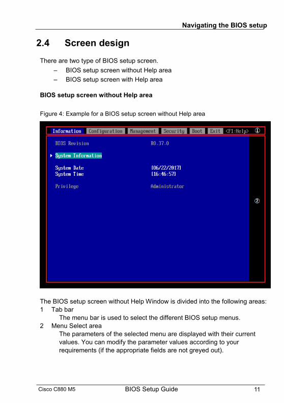
2.4 Screen design There are two type of BIOS setup screen.
– BIOS setup screen without Help area – BIOS setup screen with Help area
BIOS setup screen without Help area Figure 4: Example for a BIOS setup screen without Help area
The BIOS setup screen without Help Window is divided into the following areas: 1 Tab bar
The menu bar is used to select the different BIOS setup menus. 2 Menu Select area
The parameters of the selected menu are displayed with their current values. You can modify the parameter values according to your requirements (if the appropriate fields are not greyed out).

Navigating the BIOS setup
BIOS Setup Guide Cisco C880 M5 12
BIOS setup screen with Help area Figure 5: Example for a BIOS setup screen with Help area
The BIOS setup screen with Help Window is divided into the following areas: 1 Tab bar
The menu bar is used to select the different BIOS setup menus. 2 Menu Select area
The parameters of the selected menu are displayed with their current values. You can modify the parameter values according to your requirements (if the appropriate fields are not greyed out).
3 Menu Select Help area Brief information is displayed in the help area.
4 Operations Help area The operations area lists the keys available for use with BIOS setup.
2.5 Exiting the BIOS setup ► In the Exit menu select the required parameter and press the Enter key.

Information menu
BIOS Setup Guide Cisco C880 M5 13
3 Information menu This menu displays information of BIOS Revision, System Time/Date and Privilege.
Figure 6: Example for the “Information menu”
BIOS Revision
Displays the BIOS Revision on the system. System Information [USER]
The System Information window displays an overview about the system configuration. This includes CPU, memory and LAN configuration data.
System Time / System Date [USER] [APPLY] Displays the current date/time set on the system. The system time has the format HH:MM:SS The system date has the format MM/DD/YYYY.

Information menu
BIOS Setup Guide Cisco C880 M5 14
To change the current time/date settings enter the new time/date in the System Time/System Date fields respectively. Use the Tab key to move the cursor within the System Time and the System Date fields.
If the system time and date are lost after you switch the system off and back on again, the lithium battery is empty and needs to be replaced.
Privilege Displays the current Access Privilege in BIOS setup utility. Administrator
In case Administrator password was entered or the system is not password protected the Access Privilege is Administrator.
User If the User Password was set and User password was entered the user will have User level.
If Administrator and User password are assigned the Access Privilege depends on the password used for entering BIOS setup utility.
Information menu
BIOS Setup Guide Cisco C880 M5 15
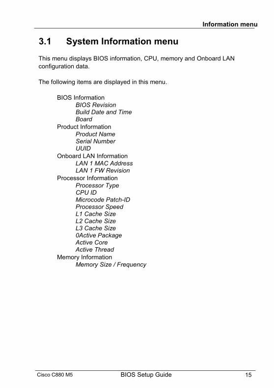
3.1 System Information menu This menu displays BIOS information, CPU, memory and Onboard LAN configuration data. The following items are displayed in this menu.
BIOS Information BIOS Revision Build Date and Time Board
Product Information Product Name Serial Number UUID
Onboard LAN Information LAN 1 MAC Address LAN 1 FW Revision
Processor Information Processor Type CPU ID Microcode Patch-ID Processor Speed L1 Cache Size L2 Cache Size L3 Cache Size 0Active Package Active Core Active Thread
Memory Information Memory Size / Frequency

Configuration menu
BIOS Setup Guide Cisco C880 M5 16
4 Configuration menu CAUTION! Only change the default settings if required for a special purpose. Incorrect settings in this menu can result in malfunctions on your system!
Figure 7: Example for the “Configuration menu”
Onboard Devices Configuration [USER] Calls a submenu used to configure Onboard Devices. Some of them are only available under special preconditions (see “4.1 Onboard Devices Configuration” on page 18).
PCI Subsystem Configuration [USER] Calls a submenu used to set up the PCI subsystem configuration (see ”4.2 PCI Subsystem Configuration” page on 19).

Configuration menu
BIOS Setup Guide Cisco C880 M5 17
CPU Configuration [USER] Calls a submenu used to make additional processor settings (see “4.3 CPU Configuration” page on 22). The adjustment options available in this submenu depend on the processor being used.
Memory Configuration [USER] Calls a submenu used to setup the memory subsystems (see "4.4 Memory configuration” page on 31).
SATA Configuration [USER] Calls a submenu containing the settings for the corresponding SATA controller (see “4.5 SATA Configuration” on page 33).
CSM Configuration [USER] Opens the submenu for configuring the Compatibility Support Module (CSM) (see ”4.6 CSM Configuration” on page 34).
Security Configuration [USER] Calls a submenu used to set up the TPM device (see “4.7 Security Configuration” on page 36). If the system has no TPM devices, this item is not displayed.
USB Configuration [USER] Calls a submenu used to set up the USB components on the system board (see “4.8 USB Configuration” on page 37).
Super IO Configuration [USER] Calls a submenu used to configure System Super IO Chip parameters (see ”4.9 Super IO Configuration” on page 38).
UEFI Network Stack Configuration [USER] Calls a submenu used to set up the UEFI network stack (see “4.10 UEFI Network Stack Configuration” on page 39).
Power Configuration [USER] Calls a submenu used to set up the Power Management (see ”4.11Power Configuration” on page 40).
iSCSI Configuration [ADMIN] Calls a submenu used to configure a UEFI driver for a LAN controller (see “4.12 iSCSI Configuration” on page 41).

Configuration menu
BIOS Setup Guide Cisco C880 M5 18
Driver Health [USER]
Calls a submenu to refer Driver status (see “4.13 Driver Health” on page 46).
The contents displayed in this submenu are driver dependent. Cisco C880 M5 does not guarantee the contents displayed in this submenu.
PCI Device Setting menus other than above menu are displayed by EFI Driver of each PCI Device. Contents displayed depend on the EFI Driver.
4.1 Onboard Devices Configuration Opens the submenu to configure Onboard LAN Devices. LAN Controller [ADMIN]
Specifies whether the Onboard LAN can be used. Disabled
Onboard LAN Controller is disabled. Onboard LAN cannot be used.
Enabled [Initial Value] Onboard LAN Controller is enabled. Onboard LAN can be used.
LAN 1 Oprom [ADMIN]
This parameter specifies whether an Option ROM should be started and if so which type of Option ROM. Whether to start with UEFI boot or with Legacy boot depends on the setting of “Launch PXE OpROM Policy” in “CSM Configuration menu”. Disabled
Do not start any Option ROM. PXE [Initial Value]
Starts the PXE Option ROM to provide the functionality for booting via PXE.
iSCSI Starts the iSCSI Option ROM to provide the functionality for booting via SCSI. In case LAN Controller is disabled, this item is not displayed.

Configuration menu
BIOS Setup Guide Cisco C880 M5 19
4.2 PCI Subsystem Configuration The following parameters can be set in this menu. ASPM Support [ADMIN]
Active State Power Management (ASPM) is used to power-manage the PCI Express links, thus consuming less power. Even if ASPM is generally enabled by this selection, it will only be enabled for a specific link if the appropriate PCI Express expansion card or onboard controller supports it also. Disabled [Initial Value]
ASPM is disabled. Power consumption for PCI Express links is not reduced. Best compatibility.
L1 only Low power mode of the PCI Express links is set to L1. Tradeoff between compatibility and energy saving. The latency for PCI Express devices may increase if ASPM is not disabled. Several expansion cards do not support this feature correctly, which may lead to an undefined system behavior.
Above 4G Decoding [ADMIN] Specifies if memory resources above the 4 GB address boundary can be assigned to PCI devices. The selection depends on the operating system and the populated adapter cards. Disabled
Only memory resources below the 4 GB address boundary will be assigned to the PCI devices.
Enabled [Initial Value] Memory resources above the 4 GB address boundary may be assigned to PCI devices, which are capable of 64-bit address decoding. It may be required if the populated PCI Express devices (e.g. coprocessors adapter cards) are claiming a huge amount of memory resources, which no longer fits into the address space below 4 GB.

Configuration menu
BIOS Setup Guide Cisco C880 M5 20
OpROM Scan Configuration [USER] Calls a submenu to enable or disable the legacy Option ROMs of the PCI Express expansion cards (see ”4.2.1 OpROM Scan Configuration menu” page on 21).
Configuration menu
BIOS Setup Guide Cisco C880 M5 21
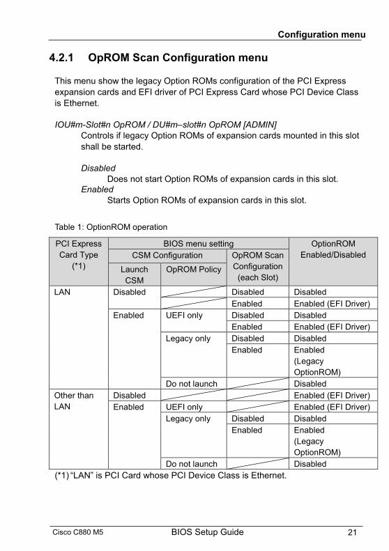
4.2.1 OpROM Scan Configuration menu
This menu show the legacy Option ROMs configuration of the PCI Express expansion cards and EFI driver of PCI Express Card whose PCI Device Class is Ethernet. IOU#m-Slot#n OpROM / DU#m–slot#n OpROM [ADMIN]
Controls if legacy Option ROMs of expansion cards mounted in this slot shall be started. Disabled
Does not start Option ROMs of expansion cards in this slot. Enabled
Starts Option ROMs of expansion cards in this slot.
Table 1: OptionROM operation
PCI Express Card Type
(*1)
BIOS menu setting OptionROM Enabled/Disabled CSM Configuration OpROM Scan
Configuration (each Slot)
Launch CSM
OpROM Policy
LAN Disabled Disabled Disabled Enabled Enabled (EFI Driver)
Enabled UEFI only Disabled Disabled Enabled Enabled (EFI Driver)
Legacy only Disabled Disabled Enabled Enabled
(Legacy OptionROM)
Do not launch Disabled Other than LAN
Disabled Enabled (EFI Driver) Enabled UEFI only Enabled (EFI Driver)
Legacy only Disabled Disabled Enabled Enabled
(Legacy OptionROM)
Do not launch Disabled (*1) “LAN” is PCI Card whose PCI Device Class is Ethernet.

Configuration menu
BIOS Setup Guide Cisco C880 M5 22
4.3 CPU Configuration The following parameters can be set in this menu. Hyper-Threading [ADMIN]
Hyper-threading technology allows a single physical processor core to appear as several logical processors. With this technology the operating system can better utilize the internal processor resources, which in turn leads to increased performance. The advantages of this technology can only be used by an operating system which supports ACPI. This setting has no effect on operating systems which do not support ACPI. Disabled
An ACPI operating system can only use the first logical processor of a processor core. This setting should only be used if hyper-threading technology has not been correctly implemented in the ACPI operating system.
Enabled [Initial Value] An ACPI operating system can use all logical processors within a physical processor.
Active Processor Cores [ADMIN] For processors that contain multiple processor cores, the number of active processor cores can be limited. Inactive processor cores will not be used and hidden from the operating system. 0…28 can always be selected regardless of the actual core number of the CPU. If selected number is more than the core number of the CPU, all available processor cores are active. 0 [Initial Value]
All available processor cores are active and can be used. 1...28
Only the selected number of processor cores are active. The remaining processor cores are deactivated.
This selection may solve problems with specific software packages or system licenses.

Configuration menu
BIOS Setup Guide Cisco C880 M5 23
Hardware Prefetcher [ADMIN] If activated memory content, that is likely required, is preloaded automatically to the cache when the memory bus is inactive. Fetching content form cache instead of memory reduces the latency especially for applications with linear data access.
With this parameter you can change the performance settings for non-standard applications. It is recommended that you should adhere to the default settings for standard applications.
Disabled Deactivates the hardware prefetcher of the CPU.
Enabled [Initial Value] Activates the hardware prefetcher of the CPU.
Adjacent Cache Line Prefetch [ADMIN]
Available if the processor offers a mechanism for loading an additional adjacent 64 Byte cache line during every cache request of the processor. This will increase cache hit ratio for applications with high spatial locality.
With this parameter you can change the performance settings for non-standard applications. It is recommended that you should adhere to the default settings for standard applications.
Disabled The processor loads the requested cache line.
Enabled [Initial Value] The processor loads the requested cache line and the adjacent cache line.
DCU Streamer Prefetcher [ADMIN] If activated data content, that is likely required, is preloaded automatically to the L1 data cache when the memory bus is inactive. Fetching content from cache instead of memory reduces the latency especially for applications with linear data access.
With this parameter you can change the performance settings for non-standard applications. It is recommended that you should adhere to the default settings for standard applications.
Disabled Deactivates the DCU Streamer Prefetcher of the CPU.
Enabled [Initial Value]

Configuration menu
BIOS Setup Guide Cisco C880 M5 24
Activates the DCU Streamer Prefetcher of the CPU.
DCU IP Prefetcher [USER] Performance gains are expected when code is organized sequentially and in contiguous memory.
With this parameter you can change the performance settings for non-standard applications. It is recommended that you should adhere to the default settings for standard applications.
Disabled Deactivates the DCU IP Prefetch of the CPU.
Enabled [Initial Value] Activates the DCU IP Prefetch of the CPU.
Intel Virtualization Technology [ADMIN]
Supports the virtualization of platform hardware and several software environments, based on VMX (Virtual Machine Extensions) to support the use of several software environments using virtual computers. Virtualization technology extends the processor support for virtualization purposes with the 16 Bit and 32 Bit protected modes and with the EM64T (Intel® Extended Memory 64 Technology) mode. Disabled
A VMM (Virtual Machine Monitor) cannot use the additional hardware features.
Enabled [Initial Value] A VMM can use the additional hardware features.
Intel VT-d [ADMIN]
Intel VT-d (Virtualization Technology for Directed I/O) provides hardware support for sharing I/O devices between multiple virtual machines. VMMs (Virtual Machine Monitors) can use Intel VT-d for managing multiple virtual machines accessing the same physical I/O device. Disabled
Intel VT-d is disabled and not available for VMMs. Enabled/ [Initial Value]
Intel VT-d for VMMs is enabled.

Configuration menu
BIOS Setup Guide Cisco C880 M5 25
Intel TXT Support [ADMIN] Sets Enabled/Disabled of Intel Trusted Execution Technology function. To enable Intel TXT support, it is required that “Enabled” is set in both “Intel Vt-d” menu and “Security Configuration” menu. Disabled [Initial Value]
Intel TXT function is enabled. Enabled
Intel TXT function is disabled.
Power Technology [ADMIN] Configures CPU power management features. Disabled
CPU power management features are disabled. Energy Efficient
CPU power management features are optimized for energy efficiency.
Custom [Initial Value] Additional Setup items to configure CPU power management will be usable.
Enhanced SpeedStep [ADMIN] Defines the processor voltage and frequency. EIST (Enhanced Intel SpeedStep(R) Technology) is an energy saving function. This menu is displayed when “Custom“ is set in “Power Technology” menu.
The processor voltage is adapted to the respective system requirements. A reduction in the clock frequency causes less power to be required by the system.
Disabled Enhanced SpeedStep functionality is disabled.
Enabled [Initial Value] Enhanced SpeedStep functionality is enabled.

Configuration menu
BIOS Setup Guide Cisco C880 M5 26
Turbo Mode [ADMIN] Allows the processor to run faster than the marked frequency if the OS requests the highest performance state (P0). This feature is also known as Intel® Turbo Boost Technology. This menu is displayed when “Custom“ is set in “Power Technology” menu. Disabled
Turbo Mode is disabled. Enabled [Initial Value]
Turbo Mode is enabled.
Energy Performance [ADMIN] Energy efficiency policy for the processor on non-legacy Operating Systems. This is an input for the processor for tuning the power consumption and the performance. This menu is displayed when “Custom“ is set in “Power Technology” menu. Performance [Initial Value]
Optimization is strongly toward performance, even at the expense of energy efficiency.
Balanced Performance Weight optimization toward performance, while conserving energy.
Balanced Energy Weight optimization toward energy conservation, with good performance.
Energy Efficient Optimization is strongly toward energy efficiency, even at the expense of performance. According to its power policy the operating system may also decide not to use the mode, which is selected in setup. It may also overrule the setup and select one of the other modes instead.
Override OS Energy Performance [ADMIN]
Prevents the OS from overruling any energy efficiency policy setting of the setup. This menu is displayed when “Custom“ is set in “Power Technology” menu. This menu is gray out when “OOB mode“ is set in “HWPM Support” menu.

Configuration menu
BIOS Setup Guide Cisco C880 M5 27
Disabled [Initial Value]
Override OS Energy Performance is disabled. Enabled
Override OS Energy Performance is enabled.
Utilization Profile [ADMIN] The Energy - Performance ratio can be optimized for different system utilizations. This menu is displayed when “Custom“ is set in “Power Technology” menu. This menu is gray out when “OOB mode“ is set in “HWPM Support” menu. Even [Initial Value]
Energy - Performance optimized for balanced system utilization. Unbalanced
Performance optimized for highly unbalanced system utilization.
P-state Coordination [ADMIN] Change P-STATE Coordination type. This menu is displayed when “Custom“ is set in “Power Technology” menu. HW_ALL [Initial Value]
Processor hardware adjusts the P-state between all logical processors in the package.
SW_ALL OS Power Manager (OSPM) coordinates the P-state between all logical processors in the physical package. All logic processors initiates transitions.
SW_ANY OS Power Manager (OSPM) coordinates the P-state between all logical processors in the package. Transitions may be initiated by any logical processor in the domain.
HWPM Support (Hardware Power Management) [ADMIN] HWPM Support for CPU for better Energy performance. This menu is displayed when “Custom“ is set in “Power Technology” menu or when “Disabled“ is set in “Enhanced SpeedStep” menu.
Disabled
HWPM function is disabled. Native mode [Initial Value]

Configuration menu
BIOS Setup Guide Cisco C880 M5 28
HWPM function is enabled. HWPM operates in NATIVE mode. OOB mode
HWPM function is enabled. HWPM operates in Out of Bound mode.
Native mode with no legacy HWPM function is enabled. HWPM operates in NATIVE mode and no legacy
CPU C1E Support [ADMIN]
If supported by the operating system the processor will be stopped when possible to save power. This menu is displayed when “Custom“ is set in “Power Technology” menu. Disabled [Initial Value]
C1E Power State functionality is not available. Enabled
C1E Power State functionality is available.
CPU C6 Report [ADMIN] Passes processor C6 state as ACPI C-3 state to OSPM to enable Processor Deep Power Down Technology. This menu is displayed when “Custom“ is set in “Power Technology” menu. Disabled [Initial Value]
CPU C6 is not exposed as ACPI C-3 state to OSPM. Enabled
CPU C6 is exposed as ACPI C-3 state to OSPM.
Package C State limit [ADMIN] Allows to configure processor C state limit. This menu is displayed when “Custom“ is set in “Power Technology” menu. C0 [Initial Value]
C0 is the C state limit. C2
C2 is the C state limit. C6
C6 is the C state limit. C6 (Retention)
C6 Retention is the C state limit.

Configuration menu
BIOS Setup Guide Cisco C880 M5 29
UPI Link Frequency Select [ADMIN]
The UPI frequency can be set to the commonly supported frequencies of the CPUs. Auto [Initial Value]
The BIOS will find out the maximum speed depending on the CPU(s) and chipset present in your system.
9.6 GT/s, 10.4 GT/s (CPU dependent) Possible speed settings vary with CPU(s) and chipset so different values are displayed depending on your system. Choose one of the values to explicitly set the speed the UPI links will be run at.
Uncore Frequency Override [ADMIN] Configures the processor uncore frequency to improve the I/O performance. Disabled [Initial Value]
The processor autonomously controls the frequency in a predefined range to save power.
Maximum The frequency is always set to its predefined maximum. This may result in an increased power consumption.
Nominal The processor autonomously controls the frequency in a predefined range to save power, but not above its nominal frequency.
Perfmon and DFX devices [ADMIN] Enable/Disable Performance monitor and DFX devices. Disabled [Initial Value]
Performance monitor and DFX devices are not available. Enabled
Performance monitor and DFX devices are available.
ACPI MSCT [ADMIN] /Enable/Disable creating of ACPI Maximum System Characteristics Table (ACPI MSCT). Disabled
Creating ACPI MSCT is not available. Enabled [Initial Value]

Configuration menu
BIOS Setup Guide Cisco C880 M5 30
Creating ACPI MSCT is available.
Uncore Frequency Scaling [ADMIN] Configures the processor uncore frequency. Disabled
The processor autonomously controls the frequency in a predefined range. This may result in a decreased power consumption.
Enabled [Initial Value] The frequency is always set to its predefined maximum.
Data Poisoning [ADMIN]
Enable/Disable Data Poisoning function. Disabled
Data poisoning function is not available. Enabled [Initial Value]
Data poisoning function is available.
Sub NUMA Clustering [ADMIN] If SNC (Sub NUMA Clustering) is enabled by the end user BIOS will configure an additional NUMA node per socket, which will optimize the performance on highly NUMA oriented workloads. For Sub NUMA Clustering systems isochronous application have to be disabled and early snooping is not supported. Auto [Initial Value]
If selected SNC will be enabled if system configuration does allow this.
Enabled SNC will be enabled.
Disabled SNC will be disabled.

Configuration menu
BIOS Setup Guide Cisco C880 M5 31
4.4 Memory configuration The following parameters can be set in this menu. Some of them are only available under special preconditions. PPR Type [ADMIN]
Selects the Post Package Repair (PPR) type.
Disabled The repair process will never be initiated.
Hard PPR [Initial Value] The repair process will be permanently. The defective row is no longer available, even after a reset or a power down.
Soft PPR The repair process will only be temporary. After a reset or a power down, the previous configuration will be restored again.
Patrol Scrub [ADMIN] Specifies whether the full memory will periodically be screened in the background. Correctable memory errors will be detected and corrected before an accumulation of such errors may lead to an uncorrectable memory error. Disabled [Initial Value]
No background memory screening will be performed, resulting in increased performance.
Enabled Background memory screening will be performed, resulting in increased reliability.
DDR4 Command/Address Parity Check and Retry [ADMIN] Enable/Disable DDR4 Command/Address Parity Check and Retry. If the performance is given priority, this function should be disabled. Disabled [Initial Value]
DDR4 Command/Address Parity Check and Retry function is not available.
Enabled DDR4 Command/Address Parity Check and Retry function is available.

Configuration menu
BIOS Setup Guide Cisco C880 M5 32
DDR4 Write Data CRC Protection [ADMIN] Enable/Disable DDR4 Write Data CRC Protection. If the performance is given priority, this function should be disabled. Disabled [Initial Value]
DDR4 Write Data CRC Protection function is not available. Enabled
DDR4 Write Data CRC Protection function is available.
FastBoot Mode [ADMIN] Enable/Disable FastBoot Mode. This function shortens the start-up time of system power on. When this function is enabled, start-up time might become not constant. If you want to keep start-up time constant, select Disabled. Disabled [Initial Value]
FastBoot Mode is not available. Enabled
FastBoot Mode is available.

Configuration menu
BIOS Setup Guide Cisco C880 M5 33
4.5 SATA Configuration The following parameters can be set in this menu. Some of them are only available under special preconditions. SATA Mode [ADMIN]
Defines in which mode the SATA ports operate. AHCI [Initial Value]
SATA interface is in AHCI Mode. RAID
SATA interface is in RAID Mode.
SATA Controller [ADMIN] Enables or disables the onboard SATA controller. Disabled
SATA Controller is not available. Enabled [Initial Value]
SATA Controller is available.
SATA Port0 (M.2 Slot#0) The M.2 SATA device name mounted to M.2 slot#0 is displayed. This menu is displayed when “AHCI” is set in “SATA Mode” menu.
SATA Port6 (M.2 Slot#1) The M.2 SATA device name mounted to M.2 slot#1 is displayed. This menu is displayed when “AHCI” is set in “SATA Mode” menu.
Configuration menu
BIOS Setup Guide Cisco C880 M5 34
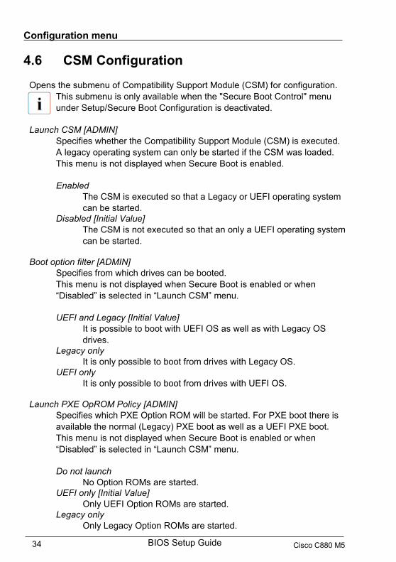
4.6 CSM Configuration Opens the submenu of Compatibility Support Module (CSM) for configuration.
This submenu is only available when the "Secure Boot Control" menu under Setup/Secure Boot Configuration is deactivated.
Launch CSM [ADMIN] Specifies whether the Compatibility Support Module (CSM) is executed. A legacy operating system can only be started if the CSM was loaded. This menu is not displayed when Secure Boot is enabled. Enabled
The CSM is executed so that a Legacy or UEFI operating system can be started.
Disabled [Initial Value] The CSM is not executed so that an only a UEFI operating system can be started.
Boot option filter [ADMIN]
Specifies from which drives can be booted. This menu is not displayed when Secure Boot is enabled or when “Disabled” is selected in “Launch CSM” menu. UEFI and Legacy [Initial Value]
It is possible to boot with UEFI OS as well as with Legacy OS drives.
Legacy only It is only possible to boot from drives with Legacy OS.
UEFI only It is only possible to boot from drives with UEFI OS.
Launch PXE OpROM Policy [ADMIN]
Specifies which PXE Option ROM will be started. For PXE boot there is available the normal (Legacy) PXE boot as well as a UEFI PXE boot. This menu is not displayed when Secure Boot is enabled or when “Disabled” is selected in “Launch CSM” menu. Do not launch
No Option ROMs are started. UEFI only [Initial Value]
Only UEFI Option ROMs are started. Legacy only
Only Legacy Option ROMs are started.

Configuration menu
BIOS Setup Guide Cisco C880 M5 35
Launch Storage OpROM policy [ADMIN]
Specifies which Storage Option ROM will be started. This menu is not displayed when Secure Boot is enabled or when “Disabled” is selected in “Launch CSM” menu. Do not launch
No Storage Option ROMs are started. UEFI only [Initial Value]
Only UEFI Storage Option ROMs are started. Legacy only
Only Legacy Storage Option ROMs are started.
Other PCI device ROM priority [ADMIN] Specifies which option ROM is booted for devices other than the network, mass storage or video. This menu is not displayed when Secure Boot is enabled or when “Disabled” is selected in “Launch CSM” menu. UEFI only [Initial Value]
Only UEFI Option ROMs are booted. Legacy only
Only Legacy Option ROMs are booted.
Configuration menu
BIOS Setup Guide Cisco C880 M5 36
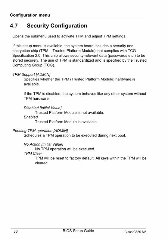
4.7 Security Configuration Opens the submenu used to activate TPM and adjust TPM settings. If this setup menu is available, the system board includes a security and encryption chip (TPM – Trusted Platform Module) that complies with TCG Specification 2.0. This chip allows security-relevant data (passwords etc.) to be stored securely. The use of TPM is standardized and is specified by the Trusted Computing Group (TCG). TPM Support [ADMIN]
Specifies whether the TPM (Trusted Platform Module) hardware is available. If the TPM is disabled, the system behaves like any other system without TPM hardware. Disabled [Initial Value]
Trusted Platform Module is not available. Enabled
Trusted Platform Module is available.
Pending TPM operation [ADMIN] Schedules a TPM operation to be executed during next boot. No Action [Initial Value]
No TPM operation will be executed. TPM Clear
TPM will be reset to factory default. All keys within the TPM will be cleared.

Configuration menu
BIOS Setup Guide Cisco C880 M5 37
4.8 USB Configuration USB Devices
Displays number of available USB devices, USB keyboards, USB Mouse and USB Hubs.
Legacy USB Support [ADMIN] Enables Legacy USB support. AUTO option disables legacy support if no USB devices are connected. DISABLE option will keep USB devices available only for EFI applications. Enabled [Initial Value]
Legacy USB Support is available. Disabled
Legacy USB Support is not available. Auto
Legacy USB Support will be disabled if no USB devices are connected.
USB Port Security [USER] Calls USB port Security menu.
Configuration menu
BIOS Setup Guide Cisco C880 M5 38
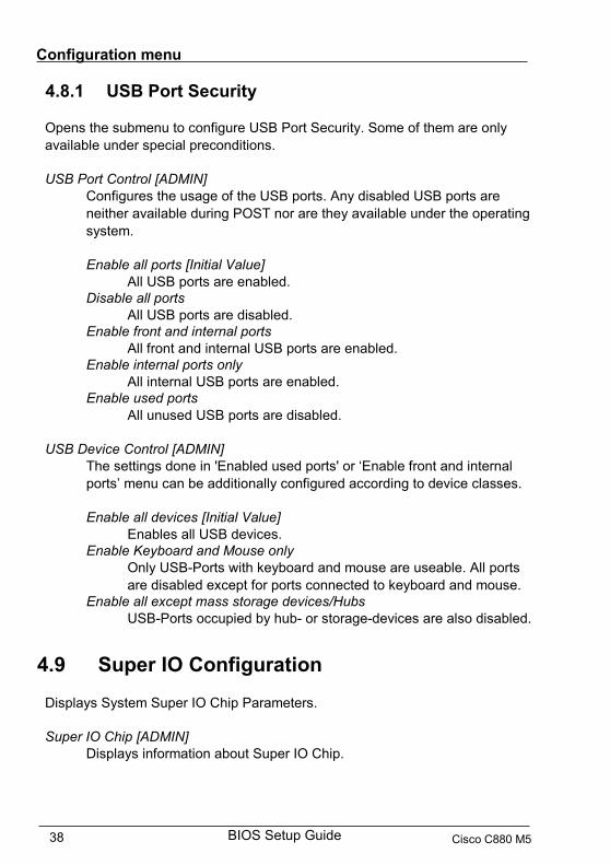
4.8.1 USB Port Security
Opens the submenu to configure USB Port Security. Some of them are only available under special preconditions. USB Port Control [ADMIN]
Configures the usage of the USB ports. Any disabled USB ports are neither available during POST nor are they available under the operating system. Enable all ports [Initial Value]
All USB ports are enabled. Disable all ports
All USB ports are disabled. Enable front and internal ports
All front and internal USB ports are enabled. Enable internal ports only
All internal USB ports are enabled. Enable used ports
All unused USB ports are disabled.
USB Device Control [ADMIN] The settings done in 'Enabled used ports' or ‘Enable front and internal ports’ menu can be additionally configured according to device classes. Enable all devices [Initial Value]
Enables all USB devices. Enable Keyboard and Mouse only
Only USB-Ports with keyboard and mouse are useable. All ports are disabled except for ports connected to keyboard and mouse.
Enable all except mass storage devices/Hubs USB-Ports occupied by hub- or storage-devices are also disabled.
4.9 Super IO Configuration Displays System Super IO Chip Parameters. Super IO Chip [ADMIN]
Displays information about Super IO Chip.

Configuration menu
BIOS Setup Guide Cisco C880 M5 39
4.10 UEFI Network Stack Configuration Network Stack [ADMIN]
Configures whether the UEFI Network Stack is available for network access under UEFI. E.g.: is the UEFI Network Stack not available there is no UEFI installation possible via PXE. Disabled
The UEFI Network Stack is not available. Enabled [Initial Value]
The UEFI Network Stack is available.
Ipv4 PXE Support [ADMIN] Enable Ipv4 PXE Boot Support. If disabled IPV4 PXE boot option will not be created. This menu is displayed when “Enabled” is selected in “Network Stack” menu. Disabled
Ipv4 PXE boot option is not available. Enabled [Initial Value]
Ipv4 PXE boot option is available.
Ipv6 PXE Support [ADMIN] Enable Ipv6 PXE Boot Support. If disabled IPV6 PXE boot option will not be created. This menu is displayed when “Enabled” is selected in “Network Stack” menu. Disabled
Ipv6 PXE boot option is not available. Enabled [Initial Value]
Ipv6 PXE boot option is available.

Configuration menu
BIOS Setup Guide Cisco C880 M5 40
4.11 Power Configuration The following parameters can be set in this menu. Some of them are only available under special preconditions. Wake-Up Resources
Calls a submenu used to make settings for Wake-Up Resources. (See “4.11.1 Wake-Up Resources” on page 40)
4.11.1 Wake-Up Resources
LAN [ADMIN] Determines whether the system can be switched on via a LAN controller (on the system board or expansion card). Disabled
The system cannot be switched on via a LAN controller. Enabled [Initial Value]
The system can be switched on via a LAN controller.
Wake On LAN boot [ADMIN] Specifies the system behavior when switched on by means of network signals. This menu is displayed when “Enabled” is selected in “LAN” menu. Boot Sequence [Initial Value]
The system boots up according to the device sequence specified in the Boot menu when switched on via LAN.
Force LAN Boot The system is booted remotely via LAN when switched on via LAN.

Configuration menu
BIOS Setup Guide Cisco C880 M5 41
4.12 iSCSI Configuration If a UEFI driver for a LAN/CNA controller (onboard CNA or PCI Express card) is loaded the parameter for booting via iSCSI can be configured here. Display format of a LAN port in this menu.
MAC: macaddress, PFA: Bus bus | Dev device | Func function macaddress : MAC Address of LAN Port bus : PCI Bus Number of LAN Port (Decimal) device : PCI Device Number of LAN Port (Decimal) function : PCI Function Number of LAN Port (Decimal)
iSCSI Initiator Name [ADMIN]
The worldwide unique name of the initiator. Only iqn. format is accepted. (4 - 223 characters)
Add an Attempt [ADMIN] Calls a submenu of MAC Selection.
Attempt attemptname [ADMIN] Calls a submenu of Attempt configuration menu.
Delete Attempt [ADMIN] Calls a submenu of Delete Attempt.
Change Attempt Order [ADMIN] Calls a submenu of Change Attempt Order.
4.12.1 MAC Selection
In this menu, the Attempt Configuration menu of each LAN port is displayed. Only settable LAN ports are displayed. Macaddress [ADMIN]
Calls a submenu of Attempt Configuration of each port.
Configuration menu
BIOS Setup Guide Cisco C880 M5 42
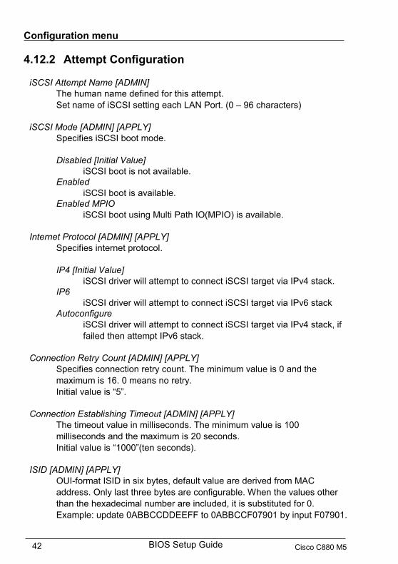
4.12.2 Attempt Configuration
iSCSI Attempt Name [ADMIN] The human name defined for this attempt. Set name of iSCSI setting each LAN Port. (0 – 96 characters)
iSCSI Mode [ADMIN] [APPLY] Specifies iSCSI boot mode. Disabled [Initial Value]
iSCSI boot is not available. Enabled
iSCSI boot is available. Enabled MPIO
iSCSI boot using Multi Path IO(MPIO) is available.
Internet Protocol [ADMIN] [APPLY] Specifies internet protocol. IP4 [Initial Value]
iSCSI driver will attempt to connect iSCSI target via IPv4 stack. IP6
iSCSI driver will attempt to connect iSCSI target via IPv6 stack Autoconfigure
iSCSI driver will attempt to connect iSCSI target via IPv4 stack, if failed then attempt IPv6 stack.
Connection Retry Count [ADMIN] [APPLY]
Specifies connection retry count. The minimum value is 0 and the maximum is 16. 0 means no retry. Initial value is “5”.
Connection Establishing Timeout [ADMIN] [APPLY] The timeout value in milliseconds. The minimum value is 100 milliseconds and the maximum is 20 seconds. Initial value is “1000”(ten seconds).
ISID [ADMIN] [APPLY] OUI-format ISID in six bytes, default value are derived from MAC address. Only last three bytes are configurable. When the values other than the hexadecimal number are included, it is substituted for 0. Example: update 0ABBCCDDEEFF to 0ABBCCF07901 by input F07901.

Configuration menu
BIOS Setup Guide Cisco C880 M5 43
Enable DHCP [ADMIN] [APPLY] Enable/Disable DHCP. This menu is not displayed when “Autoconfigure” is selected in “Internet Protocol” menu. [] [Initial Value]
DHCP is disabled. [X]
DHCP is enabled.
Initiator IP Address / Initiator Subnet Mask [ADMIN] [APPLY] Enter IP address/Subnet Mask of iSCSI initiator in dotted-decimal notation. This menu is not displayed when “[X]” is selected in “Enable DHCP” menu or when “IPv6/Autoconfigure” is selected in “Internet Protocol” menu.(7 – 15 characters) Initial value is “0.0.0.0”.
Gateway [ADMIN] [APPLY] Enter Gateway in dotted-decimal notation. This menu is not displayed when “[X]” is selected in “Enable DHCP” menu or when “IPv6/Autoconfigure” is selected in “Internet Protocol” menu.(7 – 15 characters) Initial value is “0.0.0.0”.
Get Target info via DHCP [ADMIN] [APPLY] Enable/Disable getting information of iSCSI target from DHCP server. This menu is not displayed when “Autoconfigure” is selected in “Internet Protocol” menu or when “[]” is selected in “Enable DHCP” menu. [] [Initial Value]
DHCP is disabled. [X]
DHCP is enabled.
Target Name [ADMIN] [APPLY] Set IQN name of iSCSI target. Only iqn. format is accepted. (4 – 223 characters) This menu is not displayed when “Autoconfigure” is selected in “Internet Protocol” menu or when “[X]” is selected in “Get target info via DHCP” menu.

Configuration menu
BIOS Setup Guide Cisco C880 M5 44
Target IP Address [ADMIN] [APPLY] Enter IP address of iSCSI target in dotted-decimal notation. This menu is not displayed when “Autoconfigure” is selected in “Internet Protocol” menu or when “[X]” is selected in “Get target info via DHCP” menu. (2 – 39 characters) Initial value is “0.0.0.0”.
Target Port [ADMIN] [APPLY] Set TCP listen port of iSCSI target. This menu is not displayed when “Autoconfigure” is selected in “Internet Protocol” menu or when “[X]” is selected in “Get target info via DHCP” menu. Numeric values from 0 to 65535 are possible. Initial value is “3260”.
Boot LUN [ADMIN] [APPLY] Set LUN Number of iSCSI target. This menu is not displayed when “Autoconfigure” is selected in “Internet Protocol” menu or when “[X]” is selected in “Get target info via DHCP” menu. (1 – 20 characters) Initial value is “0”. Hexadecimal representation of the LU number. Examples are:
4752-3A4F-6b7e-2F99 6734-9-156f-127 4186-9
Authentication Type [ADMIN] [APPLY]
Set Authentication Type. CHAP [Initial Value]
Authentication Type is Challenge-Handshake Authentication Protocol (CHAP).
None Authentication is none.
CHAP Type [ADMIN] [APPLY]
Set CHAP Type. This menu is displayed when “CHAP” is selected in “Authentication Type” menu.

Configuration menu
BIOS Setup Guide Cisco C880 M5 45
One way [Initial Value] CHAP is set to one way.
Mutual CHAP is set to mutual way.
CHAP Name [ADMIN] [APPLY]
Set CHAP user name. This menu is displayed when “CHAP” is selected in “Authentication Type” menu. (0 – 126 characters)
CHAP Secret [ADMIN] [APPLY] Set CHAP password. The minimum length is 12 bytes and the maximum length is 16 bytes. This menu is displayed when “CHAP” is selected in “Authentication Type” menu. (12 – 16 characters)
Reverse CHAP Name [ADMIN] [APPLY] Set Reverse CHAP user name. This menu is displayed when “CHAP” is selected in “Authentication Type” menu and “Mutual” is selected in “CHAP Type” menu. (0 – 126 characters)
Reverse CHAP Secret [ADMIN] [APPLY] Set Reverse CHAP password. The minimum length is 12 bytes and the maximum length is 16 bytes. This menu is displayed when “CHAP” is selected in “Authentication Type” menu and “Mutual” is selected in “CHAP Type” menu. (12 – 16 characters)
Save Changes [ADMIN] Save setting. Must reboot system manually to reflect changes.
Back to Previous Page [ADMIN] Back to Previous Page.

Configuration menu
BIOS Setup Guide Cisco C880 M5 46
4.12.3 Delete Attempts
In this menu, iSCSI settings can be deleted on a LAN port. By selecting the displayed device path, a menu for deleting a boot option is displayed. Commit Changes and Exit [ADMIN]
Exit this menu reflecting the change.
Discard Changes and Exit [ADMIN] Discard changes and Exit this menu.
4.12.4 Changes Attempt Order
In this menu, iSCSI settings can change the priority in the iSCSI setting. Change Attempt Order [ADMIN]
Change the priority in the iSCSI setting. Move the cursor to iSCSI Attempt Name which you change the order. Pressing the + key or the - key increases or decreases the priority of iSCSI Attempt Name.
Commit Changes and Exit [ADMIN] Exit this menu reflecting the change.
Discard Changes and Exit [ADMIN] Discard changes and Exit this menu.
4.13 Driver Health This function is not supported. The contents displayed are driver dependent. Cisco C880 M5 does not guarantee the contents displayed in this submenu.

Management menu
BIOS Setup Guide Cisco C880 M5 47
5 Management menu The following parameters can be set in this menu. Some of them are only available under special preconditions.
Figure 8: Example for the “Management menu”
Firmware Version
iRMC firmware version is displayed. SDRR Version
SDRR version is displayed. Asset Tag [ADMIN] [APPLY]
Displays the Asset Tag field of SMBIOS Type 3 (system housing chassis). For changing or inserting the Asset Tag select this setup option and press the Enter key. A window opens and you can type a character string or change the existing character string. Only alpha-numeric entries are allowed.

Management menu
BIOS Setup Guide Cisco C880 M5 48
Boot Retry Counter [ADMIN]
Specifies the maximum number of attempts to boot the operating system. Each failed attempt is followed by a system reboot after the time set in Boot Watchdog has expired. Other critical system errors also result in a system reboot and a counter decrement. After the last attempt, the system is ultimately powered off. Allowed values are: 0 to 7 number of possible retries Pressing the + key or the - key increases or decreases this value. Initial value is “3”
Power Cycle Delay [ADMIN] Specifies the minimum time that must be expired before the system can be switched on again after it has been switched off. Allowed values are: 0 sec. to 15 sec. Pressing the + key or the - key increases or decreases this value. Initial value is “7”
ASR&R Boot Delay [ADMIN]
Specifies the system reboot delay after the system shuts down as a result of an error (e.g. excessively high temperature). The system is rebooted after the set wait time has expired. Allowed values are: 0 min. to 30 min. Pressing the + key or the - key increases or decreases this value. Initial value is “2”
Temperature Monitoring [ADMIN]
Specifies if a system power-on request is executed, depending on the ambient temperature. Disabled [Initial Value]
A system power-on request is executed independent of the ambient temperature.
Enabled Prevents a system power-on if the ambient temperature is above the upper threshold value or below the lower threshold value.

Management menu
BIOS Setup Guide Cisco C880 M5 49
Fan Control [ADMIN] Specifies controlling of fans. Auto [Initial Value]
All fans are properly controlled according to the temperature. Full
All fans set to full speed and CPU performance to maximum. When all fans set to full speed, the server makes a very loud noise. You should not set to “Full” unless there are special requirements.
Event Log Full Mode [ADMIN]
Specifies whether or not the System Event Log can be overwritten. Overwrite [Initial Value]
If the System Event Log is full, additional events overwrite the oldest entries in the System Event Log. In this case, newer events are more important than older events.
Maintain If the System Event Log is full, no further events are entered. The System Event Log file must be cleared first before additional events can be entered. In this case, older events are more important than newer events.
Load iRMC Default Values [ADMIN]
Specifies whether the iRMC default values are loaded or not. No [Initial Value]
No action is taken. Yes
The iRMC default values are loaded when you choose Commit Changes and Exit to exit the BIOS setup utility. Any BIOS setup utility settings that affect the iRMC are not lost by this setting. The setting is automatically set to No after the default values are loaded.
Management menu
BIOS Setup Guide Cisco C880 M5 50
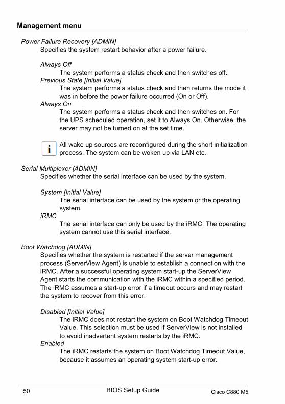
Power Failure Recovery [ADMIN] Specifies the system restart behavior after a power failure. Always Off
The system performs a status check and then switches off. Previous State [Initial Value]
The system performs a status check and then returns the mode it was in before the power failure occurred (On or Off).
Always On The system performs a status check and then switches on. For the UPS scheduled operation, set it to Always On. Otherwise, the server may not be turned on at the set time. All wake up sources are reconfigured during the short initialization process. The system can be woken up via LAN etc.
Serial Multiplexer [ADMIN] Specifies whether the serial interface can be used by the system. System [Initial Value]
The serial interface can be used by the system or the operating system.
iRMC The serial interface can only be used by the iRMC. The operating system cannot use this serial interface.
Boot Watchdog [ADMIN]
Specifies whether the system is restarted if the server management process (ServerView Agent) is unable to establish a connection with the iRMC. After a successful operating system start-up the ServerView Agent starts the communication with the iRMC within a specified period. The iRMC assumes a start-up error if a timeout occurs and may restart the system to recover from this error. Disabled [Initial Value]
The iRMC does not restart the system on Boot Watchdog Timeout Value. This selection must be used if ServerView is not installed to avoid inadvertent system restarts by the iRMC.
Enabled The iRMC restarts the system on Boot Watchdog Timeout Value, because it assumes an operating system start-up error.
Management menu
BIOS Setup Guide Cisco C880 M5 51
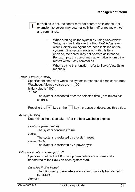
If Enabled is set, the server may not operate as intended. For example, the server may automatically turn off or restart without any commands.
– When starting up the system by using ServerView Suite, be sure to disable the Boot Watchdog, even when ServerView Agent has been installed on the system. If the system starts up with this item enabled, the server may not operate as intended. For example, the server may automatically turn off or restart without any commands.
– When setting this function, refer to ServerView Suite manuals.
Timeout Value [ADMIN]
Specifies the time after which the system is rebooted if enabled via Boot Watchdog. Allowed values are 1...100. Initial value is “100”. 1...100
The system is rebooted after the selected time (in minutes) has expired.
Pressing the + key or the - key increases or decreases this value.
Action [ADMIN] Determines the action taken after the boot watchdog expires. Continue [Initial Value]
The system continues to run. Reset
The system is restarted by a system reset. Power Cycle
The system is restarted by a power cycle.
BIOS Parameter Backup [USER] Specifies whether the BIOS setup parameters are automatically transferred to the iRMC on each system start. Disabled [Initial Value]
The BIOS setup parameters are not automatically transferred to the iRMC.
Enabled

Management menu
BIOS Setup Guide Cisco C880 M5 52
The BIOS setup parameters are automatically transferred to the iRMC on each system start.
iRMC LAN Parameters Configuration [USER] Calls a submenu used to make settings for the Remote Management Controller (see ”5.1 iRMC LAN Parameters Configuration” on page 53).
Console Redirection [USER] Calls a submenu used to make settings for the terminal communication (see “5.2 Console Redirection” on page 56).

Management menu
BIOS Setup Guide Cisco C880 M5 53
5.1 iRMC LAN Parameters Configuration The following parameters can be set in this menu. Some of them are only available under special preconditions.
iRMC MAC Address
Shows the MAC address of the iRMC. The iRMC MAC address is divided in blocks, separated by colons.
Management LAN Port [ADMIN]
Specifies which LAN interface can be used by the iRMC. The iRMC and the onboard LAN can share the LAN interface or the iRMC can use a separate LAN interface. Management [Initial Value]
The iRMC uses a separate LAN interface. Shared
The iRMC and the onboard LAN share the LAN interface.
Management LAN Speed [ADMIN] Specifies the speed for the management LAN port. Auto [Initial Value]
The speed is automatically negotiated by the LAN controller. 100 Mbit/s Full Duplex
Maximum speed at 100 Mbit/s. Simultaneous transmission in both directions is possible.
100 Mbit/s Half Duplex Maximum speed at 100 Mbit/s. Transmission is only possible in one direction at a time.
10 Mbit/s Full Duplex Fixed speed at 10 Mbit/s. Simultaneous transmission in both directions is possible.
10 Mbit/s Half Duplex Fixed speed at 10 Mbit/s. Transmission is only possible in one direction at a time.
1000 Mbit/s Maximum speed at 1000 Mbit/s.
Management VLAN [ADMIN] Enables the support of IEEE 802.1q VLAN (virtual LAN) headers for IPMI over IP sessions on IEEE 802.3 Ethernet.

Management menu
BIOS Setup Guide Cisco C880 M5 54
Enabled Enables the support of IEEE 802.1q VLAN (virtual LAN) headers for IPMI over IP sessions on IEEE 802.3 Ethernet.
Disabled [Initial Value] Disables the support of IEEE 802.1q VLAN (virtual LAN) headers for IPMI over IP sessions on IEEE 802.3 Ethernet.
VLAN ID [ADMIN] Value the VLAN headers are tagged with. Allowed values are: 0 ... 4094 Initial value is “0”.
VLAN Priority [ADMIN] Value for the VLAN user priority field to be used. Allowed values are: 0 ... 7 Initial value is “0”.
iRMC IPv4 LAN Stack [ADMIN] [APPLY]
Configures whether the IPv4 LAN Stack is available for the iRMC. Disabled
The IPv4 LAN Stack is not available for the iRMC. Enabled [Initial Value]
The IPv4 LAN Stack is available for the iRMC.
IP configuration [ADMIN] Specifies whether DHCP (Dynamic Host Configuration Protocol) support for the iRMC is used. An IP address can automatically be assigned to iRMC from a DHCP server in the network via the DHCP network protocol. This menu is displayed when “Enabled” is selected in “iRMC IPv4 LAN Stack” menu. use DHCP
The DHCP support for the iRMC is used. Local IP Address, Subnet Mask, and Gateway Address will be requested from the DHCP server.
use static configuration [Initial Value] The DHCP support for the iRMC is disabled. Local IP Address, Subnet Mask, and Gateway Address have to be entered manually.

Management menu
BIOS Setup Guide Cisco C880 M5 55
IP Address [ADMIN] [APPLY] Specifies IP address of the iRMC. Numeric values from 0 to 255 are possible. This menu is displayed when “Enabled” is selected in “iRMC IPv4 LAN Stack” menu.
Subnet Mask [ADMIN] [APPLY] Specifies the subnet mask of the iRMC. Uses the same subnet mask as in the 0operating system. Numeric values from 0 to 255 are possible. This menu is displayed when “Enabled” is selected in “iRMC IPv4 LAN Stack” menu.
Gateway Address [ADMIN] [APPLY] Specifies the gateway address of the iRMC. Numeric values from 0 to 255 are possible. This menu is displayed when “Enabled” is selected in “iRMC IPv4 LAN Stack” menu.
iRMC IPv6 LAN Stack [ADMIN] [APPLY] Configures if the IPv6 LAN Stack of the iRMC is available. Disabled
The IPv6 LAN Stack of the iRMC is not available. Enabled [Initial Value]
The IPv6 LAN Stack of the iRMC is available.
Unique Local Address [ADMIN] Displays the IPv6 address. The IP address is split into blocks separated by colons. This menu is displayed when “Enabled” is selected in “iRMC IPv6 LAN Stack” menu.
Link Local address [ADMIN] Displays the IPv6 address. The IP address is split into blocks separated by colons. This menu is displayed when “Enabled” is selected in “iRMC IPv6 LAN Stack” menu.

Management menu
BIOS Setup Guide Cisco C880 M5 56
IPv6 Router [ADMIN] Displays the address of the IPv6 router. The IP address is split into blocks separated by colons. This menu is displayed when “Enabled” is selected in “iRMC IPv6 LAN Stack” menu.
IPv6 Gateway [ADMIN]
Displays the address of the IPv6 gateway. The IP address is split into blocks separated by colons. This menu is displayed when “Enabled” is selected in “iRMC IPv6 LAN Stack” menu.
5.2 Console Redirection The following parameters can be set in this menu.
Console Redirection [ADMIN]
Specifies the interface used for communication with the terminal. Disabled
The terminal interface is disabled. Serial 1 [Initial Value]
The terminal uses the first serial interface.
Security menu
BIOS Setup Guide Cisco C880 M5 57
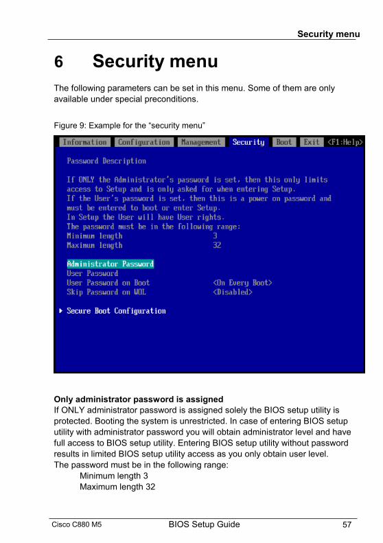
6 Security menu The following parameters can be set in this menu. Some of them are only available under special preconditions.
Figure 9: Example for the “security menu”
Only administrator password is assigned If ONLY administrator password is assigned solely the BIOS setup utility is protected. Booting the system is unrestricted. In case of entering BIOS setup utility with administrator password you will obtain administrator level and have full access to BIOS setup utility. Entering BIOS setup utility without password results in limited BIOS setup utility access as you only obtain user level. The password must be in the following range:
Minimum length 3 Maximum length 32

Security menu
BIOS Setup Guide Cisco C880 M5 58
Administrator AND user password are assigned If administrator and user password are assigned the BIOS setup utility rights depend on the entered password. Entering BIOS setup utility with administrator password results in full BIOS setup utility access, typing the user password results in limited access. Booting the system is possible with user password as well as with administrator password.
Deleting Administrator Password clears the User Password as well. If User Password is assigned the system cannot auto boot (e.g. automatic restoration after error occurrence). If your system needs auto boot, don’t set user password or set “Disabled“ in “User Password on Boot” item.
After three times password attempts, the system does not accept key input and cannot boot. If this happens, turn off the server, turn it back on, and then enter the correct password. Administrator Password [ADMIN] [APPLY]
When you press the Enter key, a window opens where you can define the administrator password. Enter a character string to define a password. If you confirm an empty password field, the password will be deleted.
To call up the complete BIOS setup utility, you need the administrator access privilege. If the administrator password is assigned the user password allows only a very limited access to the BIOS setup utility.
User Password [USER] [APPLY] When you press the Enter key, a window opens where you can define the user password. Enter a character string to define a password. The user password prevents unauthorized access to your system.
User Password on Boot [ADMIN] Specifies whether a User Password prompt appears when booting. On every Boot [Initial Value]
The password prompt appears on all boot. Disabled
The password is always taken from non-volatile storage and there is no password prompt displayed.

Security menu
BIOS Setup Guide Cisco C880 M5 59
Skip Password on WOL [ADMIN] [APPLY]
Establishes whether the user password is bypassed or must be entered when booting with Wake On LAN. Disabled [Initial Value]
The user password must be entered via the keyboard when booting the operating system.
Enabled The user password is deactivated when booting with Wake On LAN.
Secure Boot Configuration [ADMIN]
Calls a submenu used to define a firmware authentication process (see "6.1 Secure Boot Configuration" on page 60).

Security menu
BIOS Setup Guide Cisco C880 M5 60
6.1 Secure Boot Configuration Opens the submenu for configuring Secure Boot. Secure Boot Configuration defines a firmware execution authentication process. As an industry standard, Secure Boot defines how platform firmware manages certificates, authenticates firmware, and how the operating system interfaces with this process. Secure Boot Configuration is based on the Public Key Infrastructure (PKI) process to authenticate modules before they are allowed to execute. Secure Boot [ADMIN]
Indicates whether the Secure Boot function is active. [] [Initial Value]
Secure Boot is not active. [X]
Secure Boot is active.
Secure Boot Mode [ADMIN] Specifies whether the Key Management submenu is available. Standard Mode [Initial Value]
The Key Management submenu is not available. Custom Mode
The Key Management submenu is available.
This setting returns “Standard Mode” when you exit this menu.
Custom Secure Boot Options [ADMIN] Calls a submenu used to define a firmware authentication process (see "6.1.1 Custom Secure Boot Option" on page 61). This menu is displayed when “Custom Mode” is selected in “Secure Boot Mode” menu.
Security menu
BIOS Setup Guide Cisco C880 M5 61
6.1.1 Custom Secure Boot Option
Submenu for deleting, changing and adding the key and signature databases required for Secure Boot. Load Default Key [ADMIN]
Choose to Load Default Key. Initial Key is loaded. PK Options [ADMIN]
Calls a submenu of PK Options. (see "6.1.1.1 PK Options" on page 62) KEK Options [ADMIN]
Calls a submenu of KEK Options. (see "6.1.1.2 KEK Options" on page 63)
DB Options [ADMIN]
Calls a submenu of DB Options. (see "6.1.1.3 DB Options" on page 64) DBX Options [ADMIN]
Calls a submenu of DBX Options. (see "6.1.1.4 DBX Options" on page 65)
DBT Options [ADMIN]
Calls a submenu of DBT Options. (see "6.1.1.5 DBT Options" on page 66)

Security menu
BIOS Setup Guide Cisco C880 M5 62
PK Options Submenu for Setting the PK. Enroll PK [ADMIN]
Shows a submenu of Enroll PK.
Delete PK [ADMIN] Select by space key and press the Y key. The PK is deleted and [Secure Boot] is disabled.
Enroll PK [ADMIN] Select new PK in [Enroll PK Using File]. The submenu of [Save PK File] is shown.
Save PK File [ADMIN] Submenu for registering the PK.
Commit Changes and Exit [ADMIN] To save the PK File and exit this menu, select Commit Changes and Exit followed by Yes.
Discard Changes and Exit [ADMIN]
Select Discard Changes and Exit followed by Yes to discard the PK File.

Security menu
BIOS Setup Guide Cisco C880 M5 63
KEK Options Submenu for Setting the KEK. Enroll KEK [ADMIN]
Shows a submenu of Enroll KEK.
Delete KEK [ADMIN] Select by space key and press the Y key. The KEK is deleted and [Secure Boot] is disabled.
Enroll KEK [ADMIN] Submenu for Enrolling the KEK. Enroll KEK Using File [ADMIN]
The submenu of [Save KEK File] is shown.
Signature GUID [ADMIN] Set GUID. Input digit character in 11111111-2222-3333-4444-1234567890ab format. (36 characters)
Commit Changes and Exit [ADMIN]
To save the KEK File and exit this menu, select Commit Changes and Exit followed by Yes.
Discard Changes and Exit [ADMIN]
Select Discard Changes and Exit followed by Yes to discard the KEK File.
Delete KEK [ADMIN] Submenu for Delete the KEK. Select by space key and press the Y key.

Security menu
BIOS Setup Guide Cisco C880 M5 64
DB Options Submenu for Setting the DB. Enroll Signature [ADMIN]
Calls a submenu of Enroll Signature. Delete Signature [ADMIN]
Calls a submenu of Delete Signature.
Enroll Signature [ADMIN] Submenu for registering the DB.
Enroll Signature Using File [ADMIN]
The submenu of [Save KEK File] is shown.
Signature GUID [ADMIN] Set GUID. Input digit character in 11111111-2222-3333-4444-1234567890ab format. (36 characters)
Commit Changes and Exit [ADMIN]
To save the DB File and exit this menu, select Commit Changes and Exit followed by Yes.
Discard Changes and Exit [ADMIN]
Select Discard Changes and Exit followed by Yes to discard the DB File.
Delete Signature Submenu for Delete the DB. Select by space key and press the Y key.
Security menu
BIOS Setup Guide Cisco C880 M5 65
DBX Options Submenu for Setting the DBX. Enroll Signature [ADMIN]
Calls a submenu of Enroll Signature. Delete Signature [ADMIN]
Calls a submenu of Delete Signature.
Enroll Signature [ADMIN] Submenu for registering the DBX.
Enroll Signature Using File [ADMIN]
The submenu of [Save KEK File] is shown.
Signature GUID [ADMIN] Set GUID. Input digit character in 11111111-2222-3333-4444-1234567890ab format. (36 characters)
Signature Format [ADMIN]
Select Signature format.
SHA256 Signature format is SHA256.
SHA384 Signature format is SHA384.
SHA512 Signature format is SHA512.
RAW [Initial Value] Signature format is RAW.
Commit Changes and Exit [ADMIN]
To save the DBX File and exit this menu, select Commit Changes and Exit followed by Yes.
Discard Changes and Exit [ADMIN]
Select Discard Changes and Exit followed by Yes to discard the DBX File.
Delete Signature [ADMIN] Submenu for Delete the DBX. Select by space key and press the Y key.

Security menu
BIOS Setup Guide Cisco C880 M5 66
DBT Options Submenu for Setting the DBT. Enroll Signature [ADMIN]
Calls a submenu of Enroll Signature. Delete Signature [ADMIN]
Calls a submenu of Delete Signature.
Enroll Signature [ADMIN] Submenu for registering the DBT.
Enroll Signature Using File [ADMIN]
The submenu of [Save KEK File] is shown.
Signature GUID [ADMIN] Set GUID. Input digit character in 11111111-2222-3333-4444-1234567890ab format.
Commit Changes and Exit [ADMIN]
To save the DBT File and exit this menu, select Commit Changes and Exit followed by Yes.
Discard Changes and Exit [ADMIN]
Select Discard Changes and Exit followed by Yes to discard the DBT File.
Delete Signature [ADMIN] Submenu for Delete the DBX. Select by space key and press the Y key.
Boot menu
BIOS Setup Guide Cisco C880 M5 67
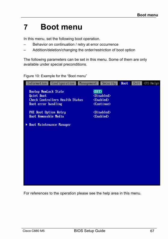
7 Boot menu In this menu, set the following boot operation. – Behavior on continuation / retry at error occurrence – Addition/deletion/changing the order/restriction of boot option The following parameters can be set in this menu. Some of them are only available under special preconditions.
Figure 10: Example for the “Boot menu”
For references to the operation please see the help area in this menu.

Boot menu
BIOS Setup Guide Cisco C880 M5 68
Bootup NumLock State [USER] [APPLY] Determines the setting of the NumLock function when the system is started up. NumLock controls the usage of the numeric keypad. On
NumLock is enabled and the numeric keypad can be used. Off [Initial Value]
NumLock is disabled and the cursor functions of the numeric keys can be used. The Num indicator on the keyboard reports the current Bootup NumLock State. The Num key on the keyboard allows to toggle between On and Off.
Quiet Boot [USER] [APPLY] The boot logo is displayed on the screen instead of the POST startup information. Disabled [Initial Value]
The POST startup information will be displayed on the screen. Enabled
The boot logo is displayed.
Check Controllers Health Status [ADMIN] When UEFI driver optional ROM of the PCI device supports the Controller Health interface, UEFI FW can query it to UEFI driver optional ROM Health Status that UEFI FW manages. Disabled
Health Status of the controller is not checked by UEFI FW. Enabled [Initial Value]
Health Status of the controller is checked by UEFI FW.
Boot error handling [ADMIN] Defines whether the system boot process is paused and the system halted when an error is detected. Continue [Initial Value]
The system boot is not paused. The error is ignored as far as possible.
Pause and wait for key If an error is detected during POST the system boot pauses.

Boot menu
BIOS Setup Guide Cisco C880 M5 69
PXE Boot Option Retry [ADMIN] Specifies if NON-EFI based PXE boot options will be retried without waiting for user input. Disabled [Initial Value]
NON-EFI boot options would not be retried without waiting for user input.
Enabled NON-EFI boot options will be retried without waiting for user input.
Boot Removable Media [ADMIN]
Specifies if support for booting to removable devices such as USB-Stick is available. Disabled
Booting to removable devices is deactivated. Enabled [Initial Value]
Booting to removable devices is activated.
Boot Maintenance Manager [ADMIN] Calls a submenu used to set up the Boot. (see "7.1 Boot Maintenance Manager" on page 70)

Boot menu
BIOS Setup Guide Cisco C880 M5 70
7.1 Boot Maintenance Manager The following parameters can be set in this menu.
– Creation / deletion / rearrangement of boot options. – Booting from the boot loader file. – Boot from CD / DVD drive. – Key input waiting time on POST screen.
Boot Options [ADMIN]
Calls a submenu of Boot Options. (see "7.1.1 Boot Options" on page 70)
Boot From File [ADMIN] Calls a submenu of Boot From File. (see "7.1.2 Boot From File" on page 72)
Set Time Out Value [ADMIN] Calls a submenu of Set Time Out Value. (see "7.1.3 Set Time Out Value" on page 72)
Reset System [ADMIN] Resets the system.
Legacy Boot Options Menu [ADMIN] Calls a submenu of Legacy Boot Options Menu. (see "7.1.4 Legacy Boot Options" on page 72)
7.1.1 Boot Options
Add / delete / reorder boot option can be set in this menu. Add Boot Option [ADMIN]
Calls a submenu of Add Boot Option. (see "7.1.1.1 Add Boot Option" on page 71)
Delete Boot Option [ADMIN] Calls a submenu of Delete Boot Option. (see "7.1.1.2 Delete Boot Option" on page 71)
Change Boot Option [ADMIN] Calls a submenu of Change Boot Order. (see "7.1.1.3 Change Boot Order" on page 71)

Boot menu
BIOS Setup Guide Cisco C880 M5 71
Add Boot Option List of the device paths that can be added to the boot option. Only UEFI Boot Option can be added in this menu. Legacy Boot Option cannot be added in this menu. By selecting the displayed device path, a menu for adding a boot option is displayed. In this menu, the screen transition cannot be performed by the Esc key. Changing this item is immediately reflected without resetting.
Delete Boot Option The boot option can be deleted in this menu. Only UEFI Boot Option can be deleted in this menu. Legacy Boot Option cannot be deleted in this menu. In this menu, the screen transition cannot be performed by the Esc key. By selecting the displayed device path, a menu for deleting a boot option is displayed. Changing this item is immediately reflected without resetting. Commit Changes and Exit [ADMIN]
To save changes and exit this menu, select Commit Changes and Exit followed by Yes.
Discard Changes and Exit [ADMIN] To discard changes and exit this menu, select Discard Changes and Exit followed by Yes.
Change Boot Order Change the order of boot option. Boot order of both UEFI Boot Option and Legacy Boot Option can be changed. However, the Legacy boot option can be changed only in the order of type (Floppy, HARDDISK, CDROM, NET, etc.). The order within each type can be changed within the Legacy Boot Option Menu. Move the cursor to Boot option which you change the order. Pressing the + key or the - key increases or decreases the priority of Boot option. In this menu, the screen transition cannot be performed by the Esc key. Changing this item is immediately reflected without resetting. Commit Changes and Exit [ADMIN]
To save changes and exit this menu, select Commit Changes and Exit followed by Yes.
Discard Changes and Exit [ADMIN] To discard changes and exit this menu, select Discard Changes and Exit followed by Yes.
Boot menu
BIOS Setup Guide Cisco C880 M5 72
7.1.2 Boot From File
List the device path of the bootable OS boot loader file. By selecting the displayed device path, boot is executed from the selected boot loader file.
7.1.3 Set Time Out Value
The key input wait time in POST window can be set up in this menu. Auto Boot Time-Out [ADMIN] [APPLY]
To set wait time in POST window. “0” means no wait. Numeric values from 0 to 65535 are possible. Initial value is “10”.
Commit Changes and Exit [ADMIN] To save changes and exit this menu, select Commit Changes and Exit followed by Yes.
Discard Changes and Exit [ADMIN] To discard changes and exit this menu, select Discard Changes and Exit followed by Yes.
7.1.4 Legacy Boot Options
The order of legacy boot options can be set up in this menu. Set Legacy Floppy Driver Order [ADMIN]
Calls a submenu of Legacy Floppy Driver Order. (see "7.1.4.1 Set Legacy Floppy Driver Order " on page 73)
Set Legacy HARDDISK Driver Order [ADMIN] Calls a submenu of Legacy HARDDISK Driver Order. (see "7.1.4.2 Set Legacy HARDDISK Driver Order" on page 73)
Set Legacy CDROM Driver Order [ADMIN] Calls a submenu of Legacy CDROM Driver Order. (see "7.1.4.3 Set Legacy CDROM Driver Order" on page 73)
Set Legacy NET Driver Order [ADMIN] Calls a submenu of Legacy NET Driver Order. (see "7.1.4.4 Set Legacy NET Driver Order" on page 74)
Boot menu
BIOS Setup Guide Cisco C880 M5 73
Set Legacy Floppy Driver Order The order of Legacy Floppy Driver can be set up in this menu. Floppy Drive #n [ADMIN] [APPLY]
Select Legacy Floppy Drive to boot with the priority in all Legacy Floppy Drive. Items are displayed as many as the number of existing Legacy Floppy Drives, and n is displayed in two digit decimal number. When Disabled is selected, it is not possible to boot from the device with the nth priority.
Commit Changes and Exit [ADMIN]
To save changes and exit this menu, select Commit Changes and Exit followed by Yes.
Discard Changes and Exit [ADMIN] To discard changes and exit this menu, select Discard Changes and Exit followed by Yes
Set Legacy HARDDISK Driver Order The order of Legacy HARDDISK Driver Order can be set up in this menu.
HardDisk Drive #n [ADMIN] [APPLY]
Select Legacy HARDDISK Driver to boot with the priority in all Legacy HARDDISK Driver. Items are displayed as many as the number of existing Legacy HARDDISK Drivers, and n is displayed in two digit decimal number. When Disabled is selected, it is not possible to boot from the device with the nth priority.
Commit Changes and Exit [ADMIN]
To save changes and exit this menu, select Commit Changes and Exit followed by Yes.
Discard Changes and Exit [ADMIN] To discard changes and exit this menu, select Discard Changes and Exit followed by Yes
Set Legacy CDROM Driver Order The order of Legacy CDROM Driver Order can be set up in this menu.
ATAPI CDROM Driver #n [ADMIN] [APPLY]
Select Legacy CDROM Driver to boot with the priority in all Legacy

Boot menu
BIOS Setup Guide Cisco C880 M5 74
CDROM Driver. Items are displayed as many as the number of existing Legacy CDROM Drivers, and n is displayed in two digit decimal number. When Disabled is selected, it is not possible to boot from the device with the nth priority.
Commit Changes and Exit [ADMIN]
To save changes and exit this menu, select Commit Changes and Exit followed by Yes.
Discard Changes and Exit [ADMIN] To discard changes and exit this menu, select Discard Changes and Exit followed by Yes
Set Legacy NET Driver Order The order of Legacy CDROM Driver Order can be set up in this menu. NET Drive #n [ADMIN] [APPLY]
Select Legacy NET Driver to boot with the priority in all Legacy NET Driver. Items are displayed as many as the number of existing Legacy NET Drivers, and n is displayed in two digit decimal number. When Disabled is selected, it is not possible to boot from the device with the nth priority.
Commit Changes and Exit [ADMIN]
To save changes and exit this menu, select Commit Changes and Exit followed by Yes.
Discard Changes and Exit [ADMIN] To discard changes and exit this menu, select Discard Changes and Exit followed by Yes

Exit menu
BIOS Setup Guide Cisco C880 M5 75
8 Exit menu The following parameters can be set in this menu.
Figure 11: Example for the “Exit menu”
Commit settings and Exit [USER]
To save the current menu entries and exit the BIOS setup utility, select Commit Changes and Exit followed by Yes. The new settings will be effective and the POST continues as long as no changed option requires a reset.
Discard settings and Exit [USER] Select Discard Changes and Exit followed by Yes to discard the changes you have made since entering BIOS setup utility or since invoking Save Changes. The BIOS setup utility will be closed and the POST continues.
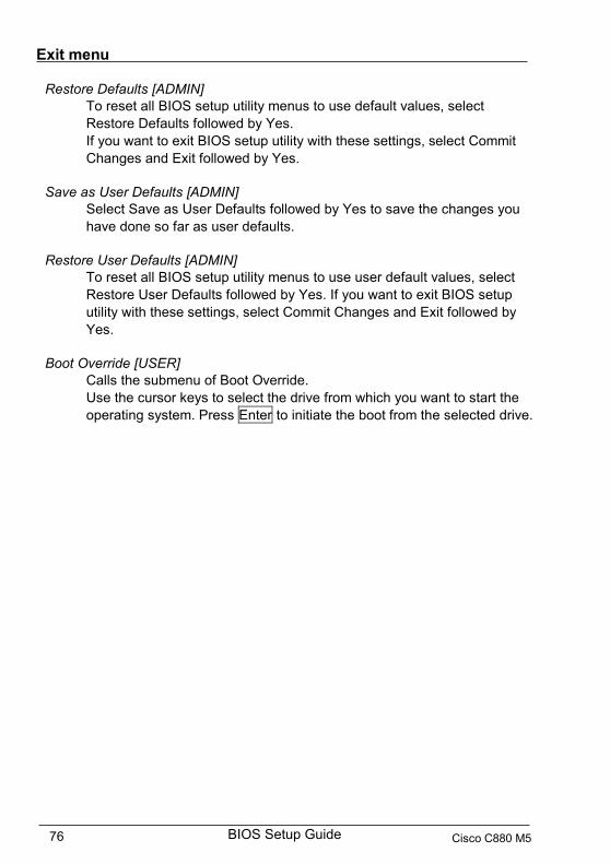
Exit menu
BIOS Setup Guide Cisco C880 M5 76
Restore Defaults [ADMIN] To reset all BIOS setup utility menus to use default values, select Restore Defaults followed by Yes. If you want to exit BIOS setup utility with these settings, select Commit Changes and Exit followed by Yes.
Save as User Defaults [ADMIN] Select Save as User Defaults followed by Yes to save the changes you have done so far as user defaults.
Restore User Defaults [ADMIN] To reset all BIOS setup utility menus to use user default values, select Restore User Defaults followed by Yes. If you want to exit BIOS setup utility with these settings, select Commit Changes and Exit followed by Yes.
Boot Override [USER] Calls the submenu of Boot Override. Use the cursor keys to select the drive from which you want to start the operating system. Press Enter to initiate the boot from the selected drive.

Appendix A Recommended setting of UEFI
BIOS Setup Guide Cisco C880 M5 77
Appendix A Recommended setting of UEFI
When they leave the factory, Cisco C880 M5 servers are already configured with BIOS standard settings, which provide an optimal ratio between performance and energy efficiency for the most common application scenarios. And yet there are situations in which it may be necessary to deviate from standard settings and thus configure the server - depending on requirements - for the maximum possible throughput (performance), the minimum possible latency (low latency), or the maximum possible energy saving (energy efficiency). The following tables list recommendations for BIOS options, which optimize the Cisco C880 M5 servers either for best performance, low latency or maximum energy efficiency. Many of the BIOS options listed here have interdependencies. This can result in certain changes to specific options alone displaying undesirable system behavior and only having the desired effect when further options are also changed at the same time. Before changes are made to the BIOS options contained in the following tables, it is expressly recommended to see the description of “4 Configuration menu”. Furthermore, any changes should first be examined in a test environment for the required effect, before transferring them to the production environment. UEFI Setup
Menu
UEFI Option Setting(*1) Performance Low latency Energy
Efficiency
CPU
Configuration
Hyper-Threading - Disabled
- Enabled Enabled Disabled Enabled
Active Processor
Cores
- 0…28 0 1…28 0
Hardware
Prefetcher
- Disabled
- Enabled Enabled Enabled Disabled
Adjacent Cache
Line Prefetch
- Disabled
- Enabled Enabled Enabled Disabled
DCU Streamer
Prefetcher
- Disabled
- Enabled Enabled Enabled Disabled
DCU Ip
Prefetcher
- Disabled
- Enabled Enabled Enabled Disabled

Appendix A Recommended setting of UEFI
BIOS Setup Guide Cisco C880 M5 78
UEFI Setup
Menu
UEFI Option Setting(*1) Performance Low latency Energy
Efficiency
Intel
Virtualization
Technology
- Disabled - Enabled
Disabled Disabled Disabled
Power
Technology
- Disabled
- Energy
Efficient
- Custom
Custom Custom Custom
Enhanced
SpeedStep (*2)
- Disabled
- Enabled Enabled Enabled
Turbo Mode (*2) - Disabled
- Enabled Enabled Enabled Enabled
Energy
Performance
(*2)
- Performance - Balanced
Performance
- Balanced
Energy
- Energy
Efficient
Performance Performance Energy
Efficient
Override OS
Energy
Performance
(*2)(*3)
- Disabled - Enabled
Disabled Disabled Disabled
P-State
Coordination (*2)
- HW_ALL - SW_ALL
- SW_ANY
HW_ALL HW_ALL HW_ALL
HWPM Support
(*2)
- Disabled
- Native mode - OOB mode
- Native mode
with no legacy
Native mode
Native mode
Native mode
CPU C1E
Support (*2)
- Disabled - Enabled
Disabled Disabled Enabled
CPU C6 Report
(*2)
- Disabled - Enabled
Disabled Disabled Enabled
Package C State
limit (*2)
- C0 - C2
- C6
- C6 (Retention)
C0 C0 No Limit
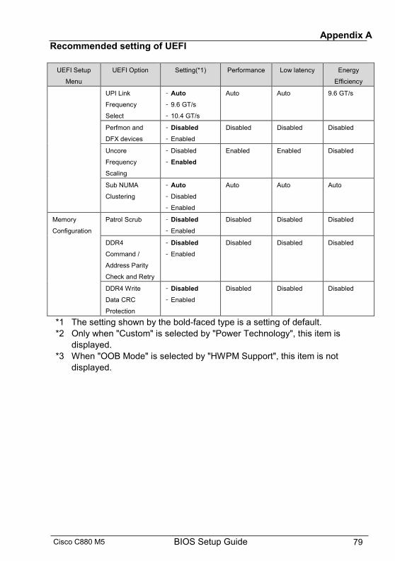
Appendix A Recommended setting of UEFI
BIOS Setup Guide Cisco C880 M5 79
UEFI Setup
Menu
UEFI Option Setting(*1) Performance Low latency Energy
Efficiency
UPI Link
Frequency
Select
- Auto - 9.6 GT/s
- 10.4 GT/s
Auto Auto 9.6 GT/s
Perfmon and
DFX devices
- Disabled - Enabled
Disabled Disabled Disabled
Uncore
Frequency
Scaling
- Disabled
- Enabled Enabled Enabled Disabled
Sub NUMA
Clustering
- Auto - Disabled
- Enabled
Auto Auto Auto
Memory
Configuration
Patrol Scrub - Disabled - Enabled
Disabled Disabled Disabled
DDR4
Command /
Address Parity
Check and Retry
- Disabled - Enabled
Disabled Disabled Disabled
DDR4 Write
Data CRC
Protection
- Disabled - Enabled
Disabled Disabled Disabled
*1 The setting shown by the bold-faced type is a setting of default. *2 Only when "Custom" is selected by "Power Technology", this item is
displayed. *3 When "OOB Mode" is selected by "HWPM Support", this item is not
displayed.
Index
BIOS Setup Guide Cisco C880 M5 80
Index
A Above 4G Decoding, 19 ACPI MSCT, 29 Action, 51 Active Processor Cores, 22 Add an Attempt, 41 Add Boot Option, 70 Adjacent Cache Line Prefetch, 23 Administrator Password, 58 ASPM Support, 19 ASR&R Boot Delay, 48 Asset Tag, 47 ATAPI CDROM Driver, 73 Attempt attemptname, 41 Authentication Type, 44 Auto Boot Time-Out, 72
B BIOS Parameter Backup, 51 BIOS Revision, 13 Boot error handling, 68 Boot LUN, 44 Boot Maintenance Manager, 69 Boot option filter, 34 Boot Override, 76 Boot Removable Media, 69 Boot Retry Counter, 48 Boot Watchdog, 50 Bootup NumLock State, 68
C Change Attempt Order, 41 Change Boot Option, 70 CHAP Name, 45 CHAP Secret, 45 CHAP Type, 44 Check Controllers Health Status, 68 Commit settings and Exit, 75
Connection Establishing Timeout, 42 Connection Retry Count, 42 Console Redirection, 52 CPU C1E Support, 28 CPU C6 Report, 28 CPU Configuration, 17 CSM Configuration, 17 Custom Secure Boot Options, 60
D Data Poisoning, 30 DB Options, 61 DBT Options, 61 DBX Options, 61 DCU IP Prefetcher, 24 DCU Streamer Prefetcher, 23 DDR4 Command/Address Parity
Check and Retry, 31 DDR4 Write Data CRC Protection, 32 Delete Attempt, 41 Delete Boot Option, 70 Disabled, 19 Discard settings and Exit, 75 Driver Health, 18
E Enable CPU HWPM, 27 Enable DHCP, 43 Energy Performance, 26 Enhanced SpeedStep, 25 Event Log Full Mode, 49
F Fan Control, 49 FastBoot Mode, 32 Firmware Version, 47 Floppy Drive, 73

Index
BIOS Setup Guide Cisco C880 M5 81
G Gateway, 43 Gateway Address, 55 Get Target info via DHCP, 43
H HardDisk Drive, 73 Hardware Prefetcher, 23 Hyper-Threading, 22
I Initiator IP Address / Initiator Subnet
Mask, 43 Intel TXT Support, 25 Intel Virtualization Technology, 24 Internet Protocol, 42 IOU#m-Slot#n OpROM / DU#m–
slot#n OpROM, 21 IP Address, 55 IP configuration, 54 IPv6 Gateway, 56 IPv6 Router, 56 iRMC IPv4 LAN Stack, 54 iRMC IPv6 LAN Stack, 55 iRMC Lan Parameters Configuration,
52 iRMC MAC Address, 53 iSCSI Attempt Name, 42 iSCSI Configuration, 17 iSCSI Initiator Name, 41 iSCSI Mode, 42 ISID, 42
K KEK Options, 61
L LAN, 40 LAN 1 Oprom, 18 LAN Controller, 18 Launch CSM, 34 Launch PXE OpROM Policy, 34 Launch Storage OpROM policy, 35
Legacy USB Support, 37 Link Local address, 55 Load Default Key, 61 Load iRMC Default Values, 49
M Management LAN Port, 53 Management LAN Speed, 53 Management VLAN, 53 Memory Configuration, 17
N NET Drive, 74
O Onboard Devices Configuration, 16 OpROM Scan Configuration, 20 Other PCI device ROM priority, 35 Override OS Energy Performance, 26
P Package C State limit, 28 Patrol Scrub, 31 PCI Subsystem Configuration, 16 Perfmon and DFX devices, 29 PK Options, 61 Power Configuration, 17 Power Cycle Delay, 48 Power Failure Recovery, 50 Power Technology, 25 PPR Type, 31 Privilege, 14 P-state Coordination, 27 PXE Boot Option Retry, 69 PXE-IPV4, 39 PXE-IPV6, 39
Q Quiet Boot, 68

Index
BIOS Setup Guide Cisco C880 M5 82
R Restore Defaults, 76 Restore User Defaults, 76 Reverse CHAP Name, 45 Reverse CHAP Secret, 45
S SATA Configuration, 17 SATA Controller, 33 SATA Mode, 33 SATA Port0 (M.2 Slot#0), 33 SATA Port6 (M.2 Slot#1), 33 Save as User Defaults, 76 SDRR Version, 47 Secure Boot, 60 Secure Boot Configuration, 59 Secure Boot Mode, 60 Security Configuration, 17 Serial Multiplexer, 50 Set Legacy CDROM Driver Order, 72 Set Legacy Floppy Driver Order, 72 Set Legacy HARDDISK Driver Order,
72 Set Legacy NET Driver Order, 72 Skip Password on WOL, 59 SNC Enable, 30 Subnet Mask, 55 Super IO Chip, 38 Super IO Configuration, 17 System Information, 13 System Time / System Date, 13
T Target IP Address, 44
Target Name, 43 Target Port, 44 Temperature Monitoring, 48 Timeout Value, 51 TPM2 Operation, 36 TPM2 Support, 36 Turbo Mode, 26
U UEFI Network Stack, 39 UEFI Network Stack Configuration, 17 Uncore Frequency Override, 29 Uncore Frequency Scaling, 30 Unique Local Address, 55 UPI Link Frequency Select, 29 USB Configuration, 17 USB Device Control, 38 USB Devices, 37 USB Port Control, 38 USB Port Security, 37 User Password, 58 User Password on Boot, 58 Utilization Profile, 27
V VLAN ID, 54 VLAN Priority, 54 VT-d, 24
W Wake On LAN boot, 40 Wake-up Resources, 40