cisco asr 5000 3g home nodeb gateway … · ranap reset procedures ... configuring dscp marking for...
TRANSCRIPT

Cisco ASR 5x00 Series 3G Home NodeB
Gateway Administration Guide
Version 14.0
Last Updated May 31, 2013
Americas Headquarters Cisco Systems, Inc. 170 West Tasman Drive San Jose, CA 95134-1706 USA http://www.cisco.com Tel: 408 526-4000 800 553-NETS (6387) Fax: 408 527-0883
Text Part Number: OL-27198-03

THE SPECIFICATIONS AND INFORMATION REGARDING THE PRODUCTS IN THIS MANUAL ARE SUBJECT TO CHANGE WITHOUT NOTICE. ALL
STATEMENTS, INFORMATION, AND RECOMMENDATIONS IN THIS MANUAL ARE BELIEVED TO BE ACCURATE BUT ARE PRESENTED WITHOUT
WARRANTY OF ANY KIND, EXPRESS OR IMPLIED. USERS MUST TAKE FULL RESPONSIBILITY FOR THEIR APPLICATION OF ANY PRODUCTS.
THE SOFTWARE LICENSE AND LIMITED WARRANTY FOR THE ACCOMPANYING PRODUCT ARE SET FORTH IN THE INFORMATION PACKET THAT SHIPPED
WITH THE PRODUCT AND ARE INCORPORATED HEREIN BY THIS REFERENCE. IF YOU ARE UNABLE TO LOCATE THE SOFTWARE LICENSE OR LIMITED
WARRANTY, CONTACT YOUR CISCO REPRESENTATIVE FOR A COPY.
The Cisco implementation of TCP header compression is an adaptation of a program developed by the University of California, Berkeley (UCB) as part of UCB’s public domain
version of the UNIX operating system. All rights reserved. Copyright © 1981, Regents of the University of California.
NOTWITHSTANDING ANY OTHER WARRANTY HEREIN, ALL DOCUMENT FILES AND SOFTWARE OF THESE SUPPLIERS ARE PROVIDED “AS IS” WITH ALL
FAULTS. CISCO AND THE ABOVE-NAMED SUPPLIERS DISCLAIM ALL WARRANTIES, EXPRESSED OR IMPLIED, INCLUDING, WITHOUT LIMITATION, THOSE
OF MERCHANTABILITY, FITNESS FOR A PARTICULAR PURPOSE AND NONINFRINGEMENT OR ARISING FROM A COURSE OF DEALING, USAGE, OR TRADE
PRACTICE.
IN NO EVENT SHALL CISCO OR ITS SUPPLIERS BE LIABLE FOR ANY INDIRECT, SPECIAL, CONSEQUENTIAL, OR INCIDENTAL DAMAGES, INCLUDING,
WITHOUT LIMITATION, LOST PROFITS OR LOSS OR DAMAGE TO DATA ARISING OUT OF THE USE OR INABILITY TO USE THIS MANUAL, EVEN IF CISCO OR
ITS SUPPLIERS HAVE BEEN ADVISED OF THE POSSIBILITY OF SUCH DAMAGES.
Cisco and the Cisco Logo are trademarks of Cisco Systems, Inc. and/or its affiliates in the U.S. and other countries. A listing of Cisco's trademarks can be found at
www.cisco.com/go/trademarks. Third party trademarks mentioned are the property of their respective owners. The use of the word partner does not imply a partnership relationship
between Cisco and any other company.
Any Internet Protocol (IP) addresses and phone numbers used in this document are not intended to be actual addresses and phone numbers. Any examples, command display
output, network topology diagrams, and other figures included in the document are shown for illustrative purposes only. Any use of actual IP addresses or phone numbers in
illustrative content is unintentional and coincidental.
Cisco ASR 5x00 Series 3G Home NodeB Gateway Administration Guide
© 2013 Cisco Systems, Inc. All rights reserved.

Cisco ASR 5x00 Series 3G Home NodeB Gateway Administration Guide ▄ OL-27198-03 iii
CONTENTS
About this Guide ................................................................................................ ix Conventions Used .................................................................................................................................... x Contacting Customer Support ..................................................................................................................xi Additional Information .............................................................................................................................. xii
HNB Gateway in Wireless Network ................................................................. 13 Product Description ................................................................................................................................ 14
HNB Access Network Elements ......................................................................................................... 15 Home NodeB ................................................................................................................................. 15 Security Gateway (SeGW) ............................................................................................................. 16 HNB Gateway (HNB-GW) .............................................................................................................. 16 HNB Management System (HMS) ................................................................................................. 16
Licenses ............................................................................................................................................. 16 Platform Requirements....................................................................................................................... 17
Network Deployment and Interfaces ...................................................................................................... 18 HNB Gateway in 3G UMTS Network ................................................................................................. 18 Supported Logical Interfaces ............................................................................................................. 18
Features and Functionality - Base Software .......................................................................................... 21 AAA Server Group Support ................................................................................................................ 22 AAL2 Establish and Release Support ................................................................................................ 22 Access Control List Support ............................................................................................................... 22 ANSI T1.276 Compliance ................................................................................................................... 23 ATM VC Management Support .......................................................................................................... 23 Cell Broadcasting Service (CBS) Support.......................................................................................... 24 Congestion Control and Management Support .................................................................................. 24 DHCP Interface Support Between HNB-GW and HMS ..................................................................... 25 RADIUS Change of Authorization Extensions ................................................................................... 26 Emergency Call Handling ................................................................................................................... 26 GTP-U Tunnels Management Support............................................................................................... 27 HNB-UE Access Control .................................................................................................................... 27 HNB Management Function ............................................................................................................... 28 Hybrid Access Mode Support ............................................................................................................. 28 Intra-Domain Multiple CN Support Through Iu-Flex ........................................................................... 29 Iu Signalling Link Management Support ............................................................................................ 30 IuH User-Plane Transport Bearer Handling Support ......................................................................... 30 Multiple HNB-GW Service Support .................................................................................................... 30 Multiple MSC Selection without Iu-Flex.............................................................................................. 31 Network Access Control Functions through SeGW ........................................................................... 32
Authentication and Key Agreement (AKA) ..................................................................................... 32 3GPP AAA Server Support ............................................................................................................ 32 X.509 Certificate-based Authentication Support ............................................................................ 32
Open Access Mode Support .............................................................................................................. 33 QoS Management with DSCP Marking .............................................................................................. 34 RADIUS Support ................................................................................................................................ 34 UE Management Function for Pre-Rel-8 UEs .................................................................................... 35 System Management Features .......................................................................................................... 35

▀ Contents
▄ Cisco ASR 5x00 Series 3G Home NodeB Gateway Administration Guide
iv OL-27198-03
Management System Overview ..................................................................................................... 36 Bulk Statistics Support ................................................................................................................... 37 Threshold Crossing Alerts (TCA) Support ..................................................................................... 39 ANSI T1.276 Compliance ............................................................................................................... 40
Features and Functionality - Optional Enhanced Feature Software....................................................... 41 Dynamic RADIUS Extensions (Change of Authorization) .................................................................. 41 IP Security (IPSec) ............................................................................................................................. 42 Session Recovery ............................................................................................................................... 42 Web Element Management System ................................................................................................... 43
How HNB-GW Works ............................................................................................................................. 44 HNB Provisioning and Registration Procedure .................................................................................. 44 UE Registration Procedure ................................................................................................................. 46
UE Registration Procedure of Non-CSG UEs or Non-CSG HNBs ................................................ 46 Iu Connection Procedures .................................................................................................................. 48
Iu Connection Establishment Procedure ........................................................................................ 48 Network Initiated Iu Connection Release Procedure ..................................................................... 50
Paging and Serving RNS Relocation Procedures .............................................................................. 52 Paging Procedure .......................................................................................................................... 52 SRNS Relocation Procedure.......................................................................................................... 52
RANAP Reset Procedures ................................................................................................................. 53 HNB Initiated RANAP Reset Procedure ........................................................................................ 53 CN Initiated RANAP Reset Procedure ........................................................................................... 53 HNB-GW Initiated RANAP Reset Procedure ................................................................................. 53
Supported Standards .............................................................................................................................. 55 3GPP References ............................................................................................................................... 55 IETF References ................................................................................................................................ 56 ITU-T Recommendations ................................................................................................................... 58 Object Management Group (OMG) Standards .................................................................................. 59
Understanding the Service Operation ............................................................ 61 Terminology ............................................................................................................................................ 62
Contexts ............................................................................................................................................. 62 Logical Interfaces ............................................................................................................................... 62 Bindings .............................................................................................................................................. 64 Services and Networks ....................................................................................................................... 64
HNB-GW Service Configuration Procedures ................................................. 67 Information Required to Configure the System as an HNB-GW ............................................................ 68
Required Local Context Configuration Information ............................................................................ 68 Required System-Level Configuration Information ............................................................................ 69 Required Source Context Configuration Information ......................................................................... 71 Required Destination Context Configuration Information ................................................................... 73
RTP Pool Configuration .......................................................................................................................... 75 IPv4 RTP Pool Creation Over IuCS ................................................................................................... 75 IPv4 RTP Pool Creation Over Iuh ...................................................................................................... 76 RTP IP Pool Configuration Verification .............................................................................................. 76
HNB-GW Service Configuration ............................................................................................................. 78 Hashing Algorithm Configuration ........................................................................................................ 79 Iuh Interface Configuration ................................................................................................................. 80 SS7 Routing Domain Configuration ................................................................................................... 80 Peer Server Id Configuration for PS Core Network ............................................................................ 81 Peer Server Id Configuration for CS Core Network ........................................................................... 81 SCCP Network Instance Configuration .............................................................................................. 82 HNB-PS Network Configuration ......................................................................................................... 83 HNB-CS Network Configuration ......................................................................................................... 83

Contents ▀
Cisco ASR 5x00 Series 3G Home NodeB Gateway Administration Guide ▄ OL-27198-03 v
HNB-GW Global Configuration .......................................................................................................... 84 HNB-GW Service Configuration ......................................................................................................... 84 GTP-U Service Configuration ............................................................................................................. 86 x.509 Certificate Configuration ........................................................................................................... 86 Security Gateway and Crypto map Template Configuration .............................................................. 87 Multiple MSC Selection without Iu-Flex Configuration ....................................................................... 89 Open Access Mode Configuration ..................................................................................................... 89 Hybrid Access Mode Configuration .................................................................................................... 90 CBS Configuration .............................................................................................................................. 90 Verifying HNB-GW Configuration ....................................................................................................... 91
DSCP Marking Configuration ................................................................................................................. 92 Configuring DSCP Marking over Iuh Interface ................................................................................... 92 Configuring DSCP Marking for Data Packet over Iu Interface ........................................................... 92 Creating and Associating DSCP Template for Control Packets over Iu Interface ............................. 93
DHCP Configuration ............................................................................................................................... 94 Configuring DHCP Service ................................................................................................................. 94 Configuring Subscriber Template for HNB ......................................................................................... 94
IuCS over ATM Configuration ................................................................................................................ 96 Configuring the SONET Card ............................................................................................................. 96 Configuring Linkset Id and ATM Parameters ..................................................................................... 96 Configuring ALCAP Service and AAL2 Node .................................................................................... 97 Configuring the ATM Port ................................................................................................................... 98 Associating ALCAP Service with HNB-CS Network Service ............................................................. 98
Iu-Flex Configuration ............................................................................................................................ 100 Iu-Flex over IuCS Interface Configuration ........................................................................................ 100 Iu-Flex over IuPS Interface Configuration ........................................................................................ 101
Logging Facility Configuration .............................................................................................................. 102 Displaying Logging Facility ............................................................................................................... 102
Congestion Control Configuration ........................................................................................................ 104 Configuring the Congestion Control Threshold ................................................................................ 104 Configuring Service Congestion Policies ......................................................................................... 104 Configuring New Call Policy ............................................................................................................. 105
Alarm and Alert Trap Configuration ...................................................................................................... 106 SNMP-MIB Traps for HNB-GW Service ............................................................................................... 107 Event IDs for HNB-GW Service ............................................................................................................ 108
Monitoring the Service ................................................................................... 111 Monitoring System Status and Performance ........................................................................................ 112 Monitoring Logging Facility ................................................................................................................... 115 Clearing Statistics and Counters .......................................................................................................... 116
Troubleshooting the Service ......................................................................... 117 Test Commands ................................................................................................................................... 118
Using the GTPU Test Echo Command ............................................................................................ 118 Using the GTPv0 Test Echo Command ........................................................................................... 118 Using the IPsec Tunnel Test Command .......................................................................................... 119
Performance Improvement Commands ............................................................................................... 120 Turning off IPC Message Aggregation To Reduce Latency Towards Core Network ...................... 120
Engineering Rules........................................................................................... 121 DHCP Service Engineering Rules ........................................................................................................ 122 HNB-GW Engineering Rules ................................................................................................................ 123 Interface and Port Engineering Rules .................................................................................................. 124
IuCS Interface Rules ........................................................................................................................ 124 IuPS Interface Rules ........................................................................................................................ 124
▀ Contents
▄ Cisco ASR 5x00 Series 3G Home NodeB Gateway Administration Guide
vi OL-27198-03
Service Engineering Rules ................................................................................................................... 125
CoA, RADIUS DM, and Session Redirection (Hotlining) ............................. 127 RADIUS Change of Authorization and Disconnect Message ............................................................... 128
CoA Overview ................................................................................................................................... 128 DM Overview .................................................................................................................................... 128 License Requirements ...................................................................................................................... 128 Enabling CoA and DM ...................................................................................................................... 128
Enabling CoA and DM .................................................................................................................. 129 CoA and DM Attributes ................................................................................................................ 129 CoA and DM Error-Cause Attribute ............................................................................................. 130 Viewing CoA and DM Statistics ................................................................................................... 131
Session Redirection (Hotlining) ............................................................................................................ 134 Overview ........................................................................................................................................... 134
License Requirements ................................................................................................................. 134 Operation .......................................................................................................................................... 134
ACL Rule ...................................................................................................................................... 134 Redirecting Subscriber Sessions ................................................................................................. 134 Session Limits On Redirection ..................................................................................................... 135 Stopping Redirection .................................................................................................................... 135 Handling IP Fragments ................................................................................................................ 135 Recovery ...................................................................................................................................... 135 AAA Accounting ........................................................................................................................... 135
Viewing the Redirected Session Entries for a Subscriber ................................................................ 135
IP Security ........................................................................................................ 141 Overview ............................................................................................................................................... 143
Applicable Products and Relevant Sections .................................................................................... 144 IPSec Terminology ............................................................................................................................... 147
Crypto Access Control List (ACL) ..................................................................................................... 147 Transform Set ................................................................................................................................... 147 ISAKMP Policy ................................................................................................................................. 147 Crypto Map ....................................................................................................................................... 147
Manual Crypto Maps .................................................................................................................... 148 ISAKMP Crypto Maps .................................................................................................................. 148 Dynamic Crypto Maps .................................................................................................................. 148
Implementing IPSec for PDN Access Applications............................................................................... 149 How the IPSec-based PDN Access Configuration Works ................................................................ 149 Configuring IPSec Support for PDN Access .................................................................................... 150
Implementing IPSec for Mobile IP Applications .................................................................................... 152 How the IPSec-based Mobile IP Configuration Works ..................................................................... 152 Configuring IPSec Support for Mobile IP.......................................................................................... 154
Implementing IPSec for L2TP Applications .......................................................................................... 156 How IPSec is Used for Attribute-based L2TP Configurations .......................................................... 156 Configuring Support for L2TP Attribute-based Tunneling with IPSec .............................................. 158 How IPSec is Used for PDSN Compulsory L2TP Configurations .................................................... 159 Configuring Support for L2TP PDSN Compulsory Tunneling with IPSec ........................................ 160 How IPSec is Used for L2TP Configurations on the GGSN ............................................................. 161 Configuring GGSN Support for L2TP Tunneling with IPSec ............................................................ 162
Transform Set Configuration ................................................................................................................. 163 Configuring Transform Set ............................................................................................................... 163 Verifying the Crypto Transform Set Configuration ........................................................................... 163
ISAKMP Policy Configuration ............................................................................................................... 165 Configuring ISAKMP Policy .............................................................................................................. 165 Verifying the ISAKMP Policy Configuration ...................................................................................... 166

Contents ▀
Cisco ASR 5x00 Series 3G Home NodeB Gateway Administration Guide ▄ OL-27198-03 vii
ISAKMP Crypto Map Configuration ...................................................................................................... 167 Configuring ISAKMP Crypto Maps ................................................................................................... 167 Verifying the ISAKMP Crypto Map Configuration ............................................................................ 168
Dynamic Crypto Map Configuration ..................................................................................................... 170 Configuring Dynamic Crypto Maps .................................................................................................. 170 Verifying the Dynamic Crypto Map Configuration ............................................................................ 170
Manual Crypto Map Configuration ........................................................................................................ 172 Configuring Manual Crypto Maps ..................................................................................................... 172 Verifying the Manual Crypto Map Configuration .............................................................................. 173
Crypto Map and Interface Association ................................................................................................. 175 Applying Crypto Map to an Interface ................................................................................................ 175 Verifying the Interface Configuration with Crypto Map ..................................................................... 175
FA Services Configuration to Support IPSec ....................................................................................... 177 Modifying FA service to Support IPSec ............................................................................................ 177 Verifying the FA Service Configuration with IPSec .......................................................................... 178
HA Service Configuration to Support IPSec ......................................................................................... 179 Modifying HA service to Support IPSec ........................................................................................... 179 Verifying the HA Service Configuration with IPSec .......................................................................... 180
RADIUS Attributes for IPSec-based Mobile IP Applications ................................................................ 181 LAC Service Configuration to Support IPSec ....................................................................................... 182
Modifying LAC service to Support IPSec ......................................................................................... 182 Verifying the LAC Service Configuration with IPSec ........................................................................ 183
Subscriber Attributes for L2TP Application IPSec Support .................................................................. 184 PDSN Service Configuration for L2TP Support.................................................................................... 185
Modifying PDSN service to Support Attribute-based L2TP Tunneling ............................................. 185 Modifying PDSN service to Support Compulsory L2TP Tunneling .................................................. 186 Verifying the PDSN Service Configuration for L2TP ........................................................................ 186
Redundant IPSec Tunnel Fail-Over ..................................................................................................... 187 Supported Standards ....................................................................................................................... 187
Redundant IPSec Tunnel Fail-over Configuration ................................................................................ 188 Configuring Crypto Group ................................................................................................................ 188 Modify ISAKMP Crypto Map Configuration to Match Crypto Group ................................................ 189 Verifying the Crypto Group Configuration ........................................................................................ 189
Dead Peer Detection (DPD) Configuration........................................................................................... 191 Configuring Crypto Group ................................................................................................................ 191 Verifying the DPD Configuration ...................................................................................................... 192
APN Template Configuration to Support L2TP .................................................................................... 193 Modifying APN Template to Support L2TP ...................................................................................... 193 Verifying the APN Configuration for L2TP........................................................................................ 194
IPSec for LTE/SAE Networks ............................................................................................................... 195 Encryption Algorithms ...................................................................................................................... 195 HMAC Functions .............................................................................................................................. 195 Diffie-Hellman Groups ...................................................................................................................... 195 Dynamic Node-to-Node IPSec Tunnels ........................................................................................... 196 ACL-based Node-to-Node IPSec Tunnels ....................................................................................... 196 Traffic Selectors ............................................................................................................................... 196 Authentication Methods .................................................................................................................... 197 X.509 Certificate-based Peer Authentication ................................................................................... 197 Certificate Revocation Lists .............................................................................................................. 199 Child SA Rekey Support .................................................................................................................. 199 IKEv2 Keep-Alive Messages (Dead Peer Detection) ....................................................................... 200 E-UTRAN/EPC Logical Network Interfaces Supporting IPSec Tunnels .......................................... 200 IPSec Tunnel Termination ................................................................................................................ 201
IPSec for Femto-UMTS Networks ........................................................................................................ 202

▀ Contents
▄ Cisco ASR 5x00 Series 3G Home NodeB Gateway Administration Guide
viii OL-27198-03
Authentication Methods .................................................................................................................... 202 Crypto map Template Configuration ................................................................................................ 202 X.509 Certificate-based Peer Authentication ................................................................................... 203
Certificate Revocation Lists.......................................................................................................... 205 Child SA Rekey Support .............................................................................................................. 205 IKEv2 Keep-Alive Messages (Dead Peer Detection) ................................................................... 205 IPSec Tunnel Termination ............................................................................................................ 206 x.509 Certificate Configuration ..................................................................................................... 206

Cisco ASR 5x00 Series 3G Home NodeB Gateway Administration Guide ▄ OL-27198-03 ix
About this Guide
This document pertains to the features and functionality that run on and/or that are related to the Cisco® ASR 5x00
Chassis.

About this Guide
▀ Conventions Used
▄ Cisco ASR 5x00 Series 3G Home NodeB Gateway Administration Guide
x OL-27198-03
Conventions Used The following tables describe the conventions used throughout this documentation.
Icon Notice Type Description
Information Note Provides information about important features or instructions.
Caution Alerts you of potential damage to a program, device, or system.
Warning Alerts you of potential personal injury or fatality. May also alert you of potential electrical hazards.
Typeface Conventions Description
Text represented as a screen
display
This typeface represents displays that appear on your terminal screen, for example: Login:
Text represented as commands This typeface represents commands that you enter, for example: show ip access-list
This document always gives the full form of a command in lowercase letters. Commands
are not case sensitive.
Text represented as a command variable
This typeface represents a variable that is part of a command, for example: show card slot_number
slot_number is a variable representing the desired chassis slot number.
Text represented as menu or sub-
menu names
This typeface represents menus and sub-menus that you access within a software
application, for example:
Click the File menu, then click New

About this Guide
Contacting Customer Support ▀
Cisco ASR 5x00 Series 3G Home NodeB Gateway Administration Guide ▄ OL-27198-03 xi
Contacting Customer Support Use the information in this section to contact customer support.
Refer to the support area of http://www.cisco.com for up-to-date product documentation or to submit a service request.
A valid username and password are required to access this site. Please contact your Cisco sales or service representative
for additional information.
About this Guide
▀ Additional Information
▄ Cisco ASR 5x00 Series 3G Home NodeB Gateway Administration Guide
xii OL-27198-03
Additional Information Refer to the following guides for supplemental information about the system:
Cisco ASR 5000 Installation Guide
Cisco ASR 5000 System Administration Guide
Cisco ASR 5x00 Command Line Interface Reference
Cisco ASR 5x00 Thresholding Configuration Guide
Cisco ASR 5x00 SNMP MIB Reference
Web Element Manager Installation and Administration Guide
Cisco ASR 5x00 AAA Interface Administration and Reference
Cisco ASR 5x00 GTPP Interface Administration and Reference
Cisco ASR 5x00 Release Change Reference
Cisco ASR 5x00 Statistics and Counters Reference
Cisco ASR 5x00 Gateway GPRS Support Node Administration Guide
Cisco ASR 5x00 HRPD Serving Gateway Administration Guide
Cisco ASR 5000 IP Services Gateway Administration Guide
Cisco ASR 5x00 Mobility Management Entity Administration Guide
Cisco ASR 5x00 Packet Data Network Gateway Administration Guide
Cisco ASR 5x00 Packet Data Serving Node Administration Guide
Cisco ASR 5x00 System Architecture Evolution Gateway Administration Guide
Cisco ASR 5x00 Serving GPRS Support Node Administration Guide
Cisco ASR 5x00 Serving Gateway Administration Guide
Cisco ASR 5000 Session Control Manager Administration Guide
Cisco ASR 5000 Packet Data Gateway/Tunnel Termination Gateway Administration Guide
Release notes that accompany updates and upgrades to the StarOS for your service and platform

Cisco ASR 5x00 Series 3G Home NodeB Gateway Administration Guide ▄ OL-27198-03 13
Chapter 1 HNB Gateway in Wireless Network
The Cisco® provides 3GPP wireless carriers with a flexible solution that functions as a Home NodeB Gateway (HNB-
GW) in HNB Access Network to connect UEs with existing UMTS networks.
The Home NodeB Gateway works as a gateway for Home NodeBs (HNBs) to access the core networks. The HNB-GW
concentrates connections from a large amount of HNBs through IuH interface and terminates the connection to existing
Core Networks (CS or PS) using standard Iu (IuCS or IuPS) interface.
This overview provides general information about the HNB Gateway including:
Product Description
Network Deployment and Interfaces
Features and Functionality - Base Software
Features and Functionality - Optional Enhanced Feature Software
How HNB-GW Works
Supported Standards

HNB Gateway in Wireless Network
▀ Product Description
▄ Cisco ASR 5x00 Series 3G Home NodeB Gateway Administration Guide
14 OL-27198-03
Product Description The Home NodeB Gateway is the HNB network access concentrator used to connect the Home NodeBs (HNBs)/Femto
Access Point (FAP) to access the UMTS network through HNB Access Network. It aggregates Home Node-B or Femto
Access Points to a single network element and then integrates them into the Mobile Operators Voice, Data and
Multimedia networks.
Femtocell is an important technology and service offering that enables new Home and Enterprise service capabilities for
Mobile Operators and Converged Mobile Operators (xDSL/Cable/FFTH plus Wireless). The Femtocell network consists
of a plug-n-play customer premise device generically called a Home NodeB (HNB) with limited range radio access in
home or Enterprise. The HNB will auto-configure itself with the Operators network and the user can start making voice,
data and multimedia calls.
The figure given describes a high level view of UMTS network with Femtocell and HNB-GW.
Figure 1. HNB-GW Deployment in 3G UMTS Network
Once a secure tunnel has been established between the HNB and the SeGW and the HNB has been configured by the
HMS, the Operator has to connect the Femtocell network to their Core Network and services. There are several
interworking approaches to Circuit Switch (CS) and Packet Switch (PS) domains. One approach is to make the
Femtocell network appear as a standard Radio Access Network (RAN) to the Core Network. In addition to the HNB,
SeGW and HMS the RAN approach requires a network element generically called a Femto Gateway (FGW/HNB-GW).
The HNB-GW provides interworking and aggregation of large amount of Femtocell sessions toward standard CN
interfaces (IuPS/IuCS). In this approach services and mobility are completely transparent to CN elements (e.g. MSC,
xGSN).
HNB Gateway in Wireless Network
Product Description ▀
Cisco ASR 5x00 Series 3G Home NodeB Gateway Administration Guide ▄ OL-27198-03 15
The other approach is to connect the Femtocell to an IMS Network to provide CS services to subscribers when on the
Femtocell and deploy a new network element generically called a Convergence Server to provide service continuity and
mobility over standard interfaces at the MSC layer (e.g GSM-MAP, IS-41). These two approaches are clearly different
in how CS based services and mobility are achieved.
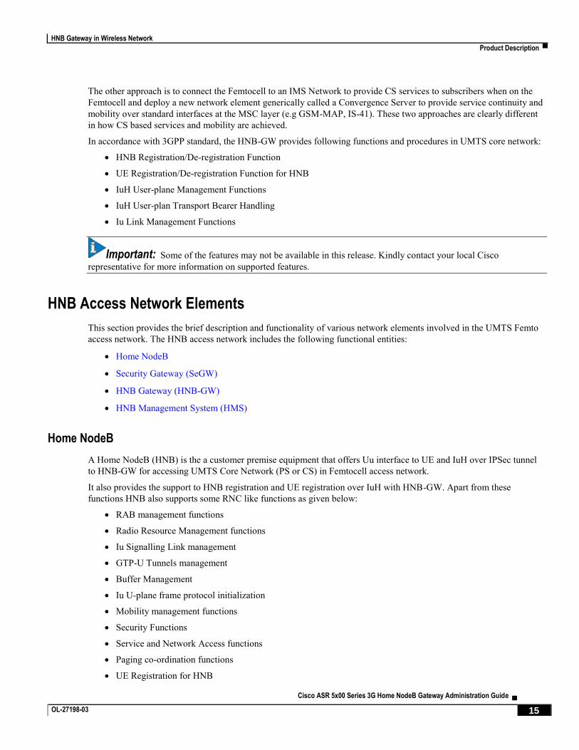
In accordance with 3GPP standard, the HNB-GW provides following functions and procedures in UMTS core network:
HNB Registration/De-registration Function
UE Registration/De-registration Function for HNB
IuH User-plane Management Functions
IuH User-plan Transport Bearer Handling
Iu Link Management Functions
Important: Some of the features may not be available in this release. Kindly contact your local Cisco
representative for more information on supported features.
HNB Access Network Elements
This section provides the brief description and functionality of various network elements involved in the UMTS Femto
access network. The HNB access network includes the following functional entities:
Home NodeB
Security Gateway (SeGW)
HNB Gateway (HNB-GW)
HNB Management System (HMS)
Home NodeB
A Home NodeB (HNB) is the a customer premise equipment that offers Uu interface to UE and IuH over IPSec tunnel
to HNB-GW for accessing UMTS Core Network (PS or CS) in Femtocell access network.
It also provides the support to HNB registration and UE registration over IuH with HNB-GW. Apart from these
functions HNB also supports some RNC like functions as given below:
RAB management functions
Radio Resource Management functions
Iu Signalling Link management
GTP-U Tunnels management
Buffer Management
Iu U-plane frame protocol initialization
Mobility management functions
Security Functions
Service and Network Access functions
Paging co-ordination functions
UE Registration for HNB

HNB Gateway in Wireless Network
▀ Product Description
▄ Cisco ASR 5x00 Series 3G Home NodeB Gateway Administration Guide
16 OL-27198-03
IuH user-plane Management functions
Security Gateway (SeGW)
Security Gateway is a logical entity in Cisco HNB-GW.
Basic function of this entity are:
Authentication of HNB
Providing access to HMS and HNB-GW
This entity terminates the secure tunnelling for IuH and TR-069 between HNB and HNB-GW and HMS respectively. In this implementation it is an optional element which is situated on HNB-GW.
HNB Gateway (HNB-GW)
The HNB-GW provides the access to Femto user to UMTS core network. It acts as an access gateway to HNB and
concentrates connections from a large amount of HNBs. The IuH interface is used between HNB and HNB-GW and
HNB-GW connects with the Core Networks (CS or PS) using the generic Iu (IuCS or IuPS) or Gn interface.
It also terminates Gn and other interfaces from UMTS core networks to provide mobile data services to HNB and to
interact with HMS to perform HNB authentication and authorization.
HNB Management System (HMS)
It is a network element management system for HNB access. Management interface between HNB and HMS is based
on TR-069 family of standards.
It performs following functions while managing HNB access network:
Facilitates HNB-GW discovery for HNB
Provision of configuration data to the HNB
Performs location verification of HNB and assigns appropriate serving elements (HMS, Security Gateway and
HNB-GW)
The HNB Management System (HMS) comprises of the following functional entities:
File Server: used for file upload or download, as instructed by TR-069 manager
TR-069 Manager: Performs CM, FM and PM functionality to the HNB through Auto-configuration server
(HMS)
Licenses
The HNB-GW is a licensed Cisco product. Separate session and feature licenses may be required. Contact your Cisco
account representative for detailed information on specific licensing requirements. For information on installing and
verifying licenses, refer to the Managing License Keys section of the Software Management Operations chapter in the
System Administration Guide.

HNB Gateway in Wireless Network
Product Description ▀
Cisco ASR 5x00 Series 3G Home NodeB Gateway Administration Guide ▄ OL-27198-03 17
Platform Requirements
The HNB-GW service runs on a Cisco® ASR 5x00 chassis running StarOS Rel. 10 or later. The chassis can be
configured with a variety of components to meet specific network deployment requirements. For additional information,
refer to the Installation Guide for the chassis and/or contact your Cisco account representative.

HNB Gateway in Wireless Network
▀ Network Deployment and Interfaces
▄ Cisco ASR 5x00 Series 3G Home NodeB Gateway Administration Guide
18 OL-27198-03
Network Deployment and Interfaces This section describes the supported interfaces and deployment scenario of HNB-GW in 3G Femto access network.
The following information is provided in this section:
HNB Gateway in 3G UMTS Network
Supported Logical Interfaces
HNB Gateway in 3G UMTS Network
The following figure displays simplified network views of the HNB-GW in an Femto access network accessing UMTS
PS or CS Core Network.
Figure 2. HNB-GW in UMTS Network and Interfaces
Supported Logical Interfaces
This section provides the brief information on supported interfaces on HNB-GW node.
In support of both mobile and network originated subscriber UE contexts, the HNB-GW provides the following network
interface support:
IuH Interface: This interface is the reference point for the control plane protocol between Home NodeB and
HNB-GW. IuH uses SCTP over IPSec IKEv2 tunnel as the transport layer protocol for guaranteed delivery of
signaling messages between HNB-GW and Home NodeB.
HNB Gateway in Wireless Network
Network Deployment and Interfaces ▀
Cisco ASR 5x00 Series 3G Home NodeB Gateway Administration Guide ▄ OL-27198-03 19
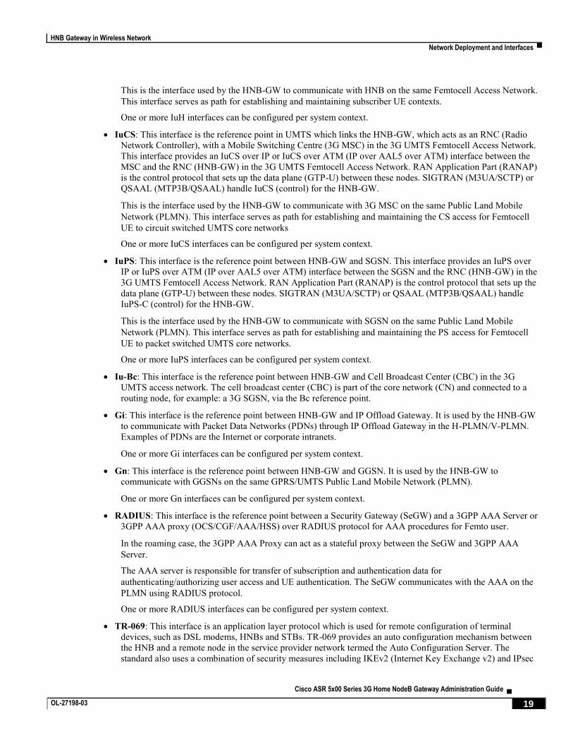
This is the interface used by the HNB-GW to communicate with HNB on the same Femtocell Access Network.
This interface serves as path for establishing and maintaining subscriber UE contexts.
One or more IuH interfaces can be configured per system context.
IuCS: This interface is the reference point in UMTS which links the HNB-GW, which acts as an RNC (Radio
Network Controller), with a Mobile Switching Centre (3G MSC) in the 3G UMTS Femtocell Access Network.
This interface provides an IuCS over IP or IuCS over ATM (IP over AAL5 over ATM) interface between the
MSC and the RNC (HNB-GW) in the 3G UMTS Femtocell Access Network. RAN Application Part (RANAP)
is the control protocol that sets up the data plane (GTP-U) between these nodes. SIGTRAN (M3UA/SCTP) or
QSAAL (MTP3B/QSAAL) handle IuCS (control) for the HNB-GW.
This is the interface used by the HNB-GW to communicate with 3G MSC on the same Public Land Mobile
Network (PLMN). This interface serves as path for establishing and maintaining the CS access for Femtocell
UE to circuit switched UMTS core networks
One or more IuCS interfaces can be configured per system context.
IuPS: This interface is the reference point between HNB-GW and SGSN. This interface provides an IuPS over
IP or IuPS over ATM (IP over AAL5 over ATM) interface between the SGSN and the RNC (HNB-GW) in the
3G UMTS Femtocell Access Network. RAN Application Part (RANAP) is the control protocol that sets up the
data plane (GTP-U) between these nodes. SIGTRAN (M3UA/SCTP) or QSAAL (MTP3B/QSAAL) handle
IuPS-C (control) for the HNB-GW.
This is the interface used by the HNB-GW to communicate with SGSN on the same Public Land Mobile
Network (PLMN). This interface serves as path for establishing and maintaining the PS access for Femtocell
UE to packet switched UMTS core networks.
One or more IuPS interfaces can be configured per system context.
Iu-Bc: This interface is the reference point between HNB-GW and Cell Broadcast Center (CBC) in the 3G
UMTS access network. The cell broadcast center (CBC) is part of the core network (CN) and connected to a
routing node, for example: a 3G SGSN, via the Bc reference point.
Gi: This interface is the reference point between HNB-GW and IP Offload Gateway. It is used by the HNB-GW
to communicate with Packet Data Networks (PDNs) through IP Offload Gateway in the H-PLMN/V-PLMN.
Examples of PDNs are the Internet or corporate intranets.
One or more Gi interfaces can be configured per system context.
Gn: This interface is the reference point between HNB-GW and GGSN. It is used by the HNB-GW to
communicate with GGSNs on the same GPRS/UMTS Public Land Mobile Network (PLMN).
One or more Gn interfaces can be configured per system context.
RADIUS: This interface is the reference point between a Security Gateway (SeGW) and a 3GPP AAA Server or
3GPP AAA proxy (OCS/CGF/AAA/HSS) over RADIUS protocol for AAA procedures for Femto user.
In the roaming case, the 3GPP AAA Proxy can act as a stateful proxy between the SeGW and 3GPP AAA
Server.
The AAA server is responsible for transfer of subscription and authentication data for
authenticating/authorizing user access and UE authentication. The SeGW communicates with the AAA on the
PLMN using RADIUS protocol.
One or more RADIUS interfaces can be configured per system context.
TR-069: This interface is an application layer protocol which is used for remote configuration of terminal
devices, such as DSL modems, HNBs and STBs. TR-069 provides an auto configuration mechanism between
the HNB and a remote node in the service provider network termed the Auto Configuration Server. The
standard also uses a combination of security measures including IKEv2 (Internet Key Exchange v2) and IPsec

HNB Gateway in Wireless Network
▀ Network Deployment and Interfaces
▄ Cisco ASR 5x00 Series 3G Home NodeB Gateway Administration Guide
20 OL-27198-03
(IP Security) protocols to authenticate the operator and subscriber and then guarantee the privacy of the data
exchanged.
One TR-069 interface can be configured per HNB node.
DHCP: This is the interface used by the HNB-GW to communicate with a Dynamic Host Control Protocol
(DHCP) Server. The system can be configured to dynamically provide IP addresses for HNBs from the DHCP
server.
Important: DHCP interface support is available in StarOS Release 14.0 and later only.

HNB Gateway in Wireless Network
Features and Functionality - Base Software ▀
Cisco ASR 5x00 Series 3G Home NodeB Gateway Administration Guide ▄ OL-27198-03 21
Features and Functionality - Base Software
This section describes the features and functions supported by default in base software on HNB-GW service and do not
require any additional license to implement the functionality with the HNB-GW service.
Following features and supports are discussed in this section:
AAA Server Group Support
AAL2 Establish and Release Support
Access Control List Support
ANSI T1.276 Compliance
ATM VC Management Support
Cell Broadcasting Service (CBS) Support
Congestion Control and Management Support
DHCP Interface Support on HNB-GW to HMS
Dynamic RADIUS Extensions (Change of Authorization)
Emergency Call Handling
GTP-U Tunnels Management Support
HNB-UE Access Control
HNB Management Function
Hybrid Access Mode Support
Intra-Domain Multiple CN Support Through Iu-Flex
Iu Signalling Link Management Support
IuH User-Plane Transport Bearer Handling Support
Multiple HNB-GW Service Support
Multiple MSC Selection without Iu-Flex
Network Access Control Functions through SeGW
Open Access Mode Support
QoS Management with DSCP Marking
RADIUS Support
System Management Features
UE Management Function for Pre-Rel-8 UEs

HNB Gateway in Wireless Network
▀ Features and Functionality - Base Software
▄ Cisco ASR 5x00 Series 3G Home NodeB Gateway Administration Guide
22 OL-27198-03
AAA Server Group Support
Value-added feature to enable VPN service provisioning for enterprise or MVNO customers. Enables each corporate
customer to maintain its own AAA servers with its own unique configurable parameters and custom dictionaries.
This feature provides support for up to 800 AAA (RADIUS and Diameter) server groups and 800 NAS IP addresses that
can be provisioned within a single context or across the entire chassis. A total of 128 servers can be assigned to an
individual server group. Up to 1,600 accounting, authentication and/or mediation servers are supported per chassis and
may be distributed across a maximum of 1,000 nodes. This feature also enables the AAA servers to be distributed across
multiple nodes within the same context.
Important: For more information on AAA Server Group configuration, if you are using StarOS 12.3 or an earlier
release, refer to the AAA and GTPP Interface Administration and Reference. If you are using StarOS 14.0 or a later
release, refer to the AAA Interface Administration and Reference.
AAL2 Establish and Release Support
Support to establish and release of ATM adaptation layer 2 (AAL2) channel within an ATM virtual connection by the
HNB-GW in complete or partial compliance with the following standards:
3GPP TS 25.414 V9.0.0 (2009-12): 3rd Generation Partnership Project; Technical Specification Group Radio
Access Network; UTRAN Iu interface data transport and transport signalling (Release 9)
3GPP TS 25.415 V8.0.0 (2008-12): 3rd Generation Partnership Project; Technical Specification Group Radio
Access Network; UTRAN Iu interface user plane protocols (Release 8)
3GPP TS 25.467 V8.0.0. (2008-12): 3rd Generation Partnership Project; Technical Specification Group Radio
Access Network; UTRAN architecture for 3G Home NodeB; Stage 2 (Release 8)
3GPP TS 25.467 V9.1.0 (2009-12): 3rd Generation Partnership Project; Technical Specification Group Radio
Access Network; UTRAN architecture for 3G Home Node B (HNB); Stage 2 (Release 9)
ITU-T Recommendation Q.2630.1: AAL type2 signalling protocol (Capability Set 1)
ITU-T Recommendation Q.2630.2: AAL type2 signalling protocol (Capability Set 2)
ITU-T Recommendation I.363.2 B: ISDN ATM Adaptation Layer (AAL) Specification: Type 2 AAL
ITU-T Recommendation I.366.1: Segmentation and Reassembly Service Specific Convergence Sublayer for
the AAL type 2
The HNB-GW connects to core network elements like MSC and SGSN over IuCS and IuPS interfaces respectively. The
Iu interface towards core network elements could either by IP based or ATM based. To provide ATM based interface
support, Cisco HNB-GW provides AAL2 support on system in order to establish a voice bearer with MSC.
Access Control List Support
Access Control Lists provide a mechanism for controlling (i.e permitting, denying, redirecting, etc.) packets in and out
of the system.
IP access lists, or Access Control Lists (ACLs) as they are commonly referred to, are used to control the flow of packets
into and out of the system. They are configured on a per-context basis and consist of “rules” (ACL rules) or filters that
control the action taken on packets that match the filter criteria

HNB Gateway in Wireless Network
Features and Functionality - Base Software ▀
Cisco ASR 5x00 Series 3G Home NodeB Gateway Administration Guide ▄ OL-27198-03 23
Once configured, an ACL can be applied to any of the following:
An individual interface
All traffic facilitated by a context (known as a policy ACL)
An individual subscriber
All subscriber sessions facilitated by a specific context
There are two primary components of an ACL:
Rule: A single ACL consists of one or more ACL rules. As discussed earlier, the rule is a filter configured to
take a specific action on packets matching specific criteria. Up to 128 rules can be configured per ACL.
Each rule specifies the action to take when a packet matches the specifies criteria. This section discusses the
rule actions and criteria supported by the system.
Rule Order: A single ACL can consist of multiple rules. Each packet is compared against each of the ACL rules,
in the order in which they were entered, until a match is found. Once a match is identified, all subsequent rules
are ignored.
Important: For more information on Access Control List configuration, refer IP Access Control List chapter in
System Administration Guide.
ANSI T1.276 Compliance
ANSI T1.276 specifies security measures for Network Elements (NE). In particular it specifies guidelines for password
strength, storage, and maintenance security measures.
ANSI T1.276 specifies several measures for password security.
These measures include:
Password strength guidelines
Password storage guidelines for network elements
Password maintenance, e.g. periodic forced password changes
These measures are applicable to the systems and the Web Element Manager since both require password
authentication. A subset of these guidelines where applicable to each platform will be implemented. A known subset of
guidelines, such as certificate authentication, are not applicable to either product. Furthermore, the platforms support a
variety of authentication methods such as RADIUS and SSH which are dependent on external elements. ANSI T1.276
compliance in such cases will be the domain of the external element. ANSI T1.276 guidelines will only be implemented
for locally configured operators.
ATM VC Management Support
Support for Asynchronous Transfer Mode (ATM) virtual circuits (VC) management function of AAL2 and AAL5
protocol by the HNB-GW in accordance with the following standards:
3GPP TR 29.814 V7.1.0 (2007-06): 3rd Generation Partnership Project; Technical Specification Group Core
Networks and Terminals Feasibility Study on Bandwidth Savings at Nb Interface with IP transport (Release 7)
HNBGW supports PVC (permanent virtual circuits) connections with CN nodes for AAL2 and AAL5 type of traffic.
The Common Part Sublayer (CPS) payload which is carried out by the AAL2 protocol over ATM is also configurable
with this feature. It provides the dynamic Common Part Sublayer (CPS) payload configuration for AAL2 protocol
HNB Gateway in Wireless Network
▀ Features and Functionality - Base Software
▄ Cisco ASR 5x00 Series 3G Home NodeB Gateway Administration Guide
24 OL-27198-03
traffic over ATM for negotiation between HNB-GW and MSC during call. Default size for payload is 45 but values may
range from 1 to 64 Bytes. This feature makes the operator to choose the CPS payload size dynamically.
Cell Broadcasting Service (CBS) Support
Cell Broadcast is a mobile technology that allows a text or binary message to be distributed to all mobile equipments
and similar devices connected to a set of cells or within a designated geographical area. Cell broadcast messages are
destined to radio cells rather than a specific or a few mobile terminals.
This technology is used in deploying location-based subscriber services for simultaneous delivery of messages to
multiple users in a specific geographical area. Cell Broadcast Center (CBC), located at the operator side, is a node
which is a source of CBS and connected to RNC in UMTS networks via standardized interface over TCP/IP protocol.
The RNC-CBC interface (Iu-BC)is described in the 3GPP standard TS25.419. CBC sends broadcasting messages to the
RNC with a list of cells/service areas (where the message is to be broadcasted) at a repetation rate at which the messages
will be broadcasted. This repetation rate depends on the type of info in the CBS messages; for example,road traffic
information will require more frequent transmission than weather information.
In case of Femto UMTS network, RNC is replaced with Home NodeB (HNB) and HNB-GW and therefore the CBC is
connected to HNB-GW through Iu-BC interface. HNB-GW routes the broadcasting messages to HNB using the
available SCTP connection with HNB. In order to exchange the broadcasting messages, Service Area Broadcast
Protocol (SABP) is used between the CBC and HNB-GW. HNB-GW forwards these SABP messages individually to
respective HNBs corresponding to the Service Area(s) present in the Service-Area list of received SABP messages by
constructing new SABP messages. HNB-originated SABP messages are individually forwarded by HNB-GW to CBC.
HNB-GW acts as an aggregator for the incoming SABP response messages from HNBs and forwards the combined
SABP message to the CBC.
Following are the major functions of SABP:
Message Handling: Broadcasting of new CB messages, amend and improve the existing broadcast messages
and to halt broadcast of particular messages.
Load Handling:Ascertaining the load on broadcast channels at any specific point of time.
Error Handling: Reporting of some basic error situations, where there are no function-specific error messages
defined.
Reset: Function to end the CB message broadcasting to specific service areas by the CBC.
Congestion Control and Management Support
Congestion Control monitors the system for conditions that could potentially degrade performance when the system is
under heavy load. Typically, these conditions are temporary (for example, high CPU or memory utilization) and are
quickly resolved. However, continuous or large numbers of these conditions within a specific time interval may have an
impact the system’s ability to service subscriber sessions. Congestion control helps identify such conditions and invokes
policies for addressing the situation.
Congestion control operation is based on configuring the following:
Congestion Condition Thresholds: Thresholds dictate the conditions for which congestion control is enabled
and establishes limits for defining the state of the system (congested or clear). These thresholds function in a
way similar to operation thresholds that are configured for the system as described in the Thresholding
Configuration Guide. The primary difference is that when congestion thresholds are reached, a service
congestion policy and an SNMP trap, starCongestion, are generated.

HNB Gateway in Wireless Network
Features and Functionality - Base Software ▀
Cisco ASR 5x00 Series 3G Home NodeB Gateway Administration Guide ▄ OL-27198-03 25
A threshold tolerance dictates the percentage under the configured threshold that must be reached in order for
the condition to be cleared. An SNMP trap, starCongestionClear, is then triggered.
Port Utilization Thresholds: If you set a port utilization threshold, when the average utilization of all
ports in the system reaches the specified threshold, congestion control is enabled.
Port-specific Thresholds: If you set port-specific thresholds, when any individual port-specific
threshold is reached, congestion control is enabled system-wide.
Service Congestion Policies: Congestion policies are configurable for each service. These policies dictate how
services respond when the system detects that a congestion condition threshold has been crossed.
Important: For more information on Congestion Control support, refer Congestion Control chapter in System
Administration Guide.
DHCP Interface Support Between HNB-GW and HMS
DHCP interface support at HNB-GW is provided to allocate IP address to HNB using DHCP procedure. Without this
support IP address is allocated using locally configured IP pool. HNB connects to HNB Security Gateway (Se-GW) via
IPSec tunnel. During IPSec tunnel establishment, HNB Se-GW allocates IP address to HNB. Femtocell provisioning
system needs HNB IP address. This is achieved by co-locating this system with DHCP server. HNB Se-GW then uses
DHCP procedure to allocate IP address to HNB.
Following is a typical message flow when HNB-GW performs as DHCP proxy:
1. HNB initiates IKE transaction by sending IKE SA INIT message to share encryption parameters.
2. Se-GW on HNB-GW responds with IKE SA INIT to confirm encryption parameters and the nonce.
3. HNB sends IKE Auth Request and includes IDi, IDr and configuration payload to request the IP address. IDi is
the IKE ID of HNB-GW.
4. HNB-GW initiates Authentication with AAA Server. HNB and AAA server exchange EAP messages.
5. Finally AAA server confirms successful authentication of HNB to HNB-GW and Subscriber template is selected
and aaa-data is returned to SessMGR by AAAMGR which contains necessary configuration and AAA returned
values.
6. HNB-GW, as with previous EAP messages, relays EAP success over IKE Auth to HNB. Steps 4, 5 and 6 are not
performed in case of certificate based authentication.
7. HNB then initiates IKE Auth request to authenticate the SA. HNB-GW selects the IP address allocation method
using the configuration from AAA-data. Method is configured to be DHCP-proxy in subscriber template. To
initiate DHCP transaction, DHCP-service is used. A suitable DHCP service is selected using configuration
parameters in AAA-data.
8. DHCP-service selects a DHCP servers using local configuration and starts DHCP transaction. DHCP
DISCOVER message is unicasted to every configured server. CID (IKE ID of HNB taken from IDi) is sent in
DHCP option (61) “Client Identifier”. The GIADDR is the DHCP Relay/Proxy IP, i.e. the IP to which the
DHCP service is bound. The GIADDR is used by the DHCP server to select the IP pool while allocating the IP.
9. If one of the DHCP servers responds (DHCP server [9] uses Failover protocol [11]) with DHCP OFFER
providing the IP address. HNB-GW validates the provided IP address with local pool to check if the address is
already being allotted to some other HNB. If so, DHCP transaction is not continued further and the HNB IKE
establishment is rejected.
10. Upon successful IP address validation for uniqueness, HNB-GW sends DHCP REQUEST message providing the
same IP address and CID. Note that Every DHCP message is sent to every configured server.
11. DHCP reserves the IP address and sends DHCP ACK confirming the IP address.
12. HNB-GW sends IKE Auth Response with allotted IP address to HNB in configuration response payload.
For this support HNB-GW is configured to communicate with DHCP server at port 61610 only and uses IKE-id of HNB
as DHCP client only.

HNB Gateway in Wireless Network
▀ Features and Functionality - Base Software
▄ Cisco ASR 5x00 Series 3G Home NodeB Gateway Administration Guide
26 OL-27198-03
Important: For more information on DHCP interface configuration, refer HNB-GW Service Configuration
Procedures.
RADIUS Change of Authorization Extensions
Important: Dynamic extensions other than RADIUS Change of Authorization (CoA) and Disconnect Message
(DM) are not supported on HNB-GW.
Dynamic RADIUS extension support provide operators with greater control over subscriber sessions by providing the
ability to dynamically manage HNB-UE White-List and/or disconnect the subscriber session.
This functionality is based on the RFC 3576, Dynamic Authorization Extensions to Remote Authentication Dial In User
Service (RADIUS), July 2003 standard.
The system supports the configuration and use of the following dynamic RADIUS extensions:
Change of Authorization: The system supports CoA messages from the AAA server to change data filters
associated with a subscriber session. The CoA request message from the AAA server must contain attributes to
identify NAS and the subscriber session and a data filter ID for the data filter to apply to the subscriber session.
Disconnect Message: The DM message is used to disconnect subscriber sessions in the system from a RADIUS
server. The DM request message should contain necessary attributes to identify the subscriber session.
The above extensions can be used to dynamically re-direct subscriber bearer to an alternate address for performing
functions such as provisioning, access control, and/or session disconnect.
Important: For more information on dynamic RADIUS extensions support, refer CoA, RADIUS, And Session
Redirection (Hotlining) chapter in System Administration Guide.
Emergency Call Handling
The HNB-GW supports the handling of Emergency call in accordance with the following standards:
3GPP TS 25.467 V9.3.0 (2010-06): 3rd Generation Partnership Project; Technical Specification Group Radio
Access Network; UTRAN architecture for 3G Home Node B (HNB); Stage 2 (Release 9)
3GPP TS 33.102 V9.1.0 (2009-12): 3rd Generation Partnership Project; Technical Specification Group Services
and System Aspects; 3G Security; Security architecture Release 9)
The HNB-GW provides access for all UE/HNB when emergency call initiated. In case of non CSG UEs or non CSG
HNBs, after Emergency call is finished, the context established between the HNB and operator’s core network entities
for UEs, who can not get access over the HNB, will be de-registered to prevent the UE from accessing non-emergency
services. However if the UE remains idle for value equal to ue-idle-time, then it will be de-registered.
HNB-GW handles the emergency call in following way:
Authentication: In case of emergency call, HNB sends a UE REGISTRATION REQUEST message with
“Registration cause” as emergency call and excludes the “UE Permanent identity” (i.e IMSI) and HNB-GW
does not perform access control for emergency call case.
Single Iu and Single RAB: In case of emergency call, HNB-GW does not allow multiple RABs for UE. This
means that UE must have only one Iu connection, either CS or PS, and have only one RAB on that Iu

HNB Gateway in Wireless Network
Features and Functionality - Base Software ▀
Cisco ASR 5x00 Series 3G Home NodeB Gateway Administration Guide ▄ OL-27198-03 27
connection. HNB-GW implements “Single IU, Single RAB policy” when UE registration comes with
Emergency.
The RUA-CONNECT has an IE called “establishment cause” which can take values as “Normal” or
“Emergency”. If UE-registration was due to emergency then RUA-CONNECT must contain “Emergency”. If
RUA-CONNECT contains “normal” then HNB-GW rejects it.
While rejecting RUA connection or RAB connection the HNB-GW uses following reject cause:
RUA - Misc: unspecified
RAB - Misc: unspecified
If UE-registration is normal then both (normal and emergency) RUA-CONNECT is allowed.
GTP-U Tunnels Management Support
Support to manage the GTP-U tunnels between HNB-GW and GSNs by in accordance with the following standards:
3GPP TS 25.467 V9.1.0 (2009-12): 3rd Generation Partnership Project; Technical Specification Group Radio
Access Network; UTRAN architecture for 3G Home Node B (HNB); Stage 2 (Release 9)
3GPP TS 25.468 V9.0.0 (2009-12): 3rd Generation Partnership Project; Technical Specification Group Radio
Access Network; UTRAN Iuh Interface RANAP User Adaptation (RUA) signalling (Release 9)
3GPP TS 25.469 V9.0.0 (2009-12): 3rd Generation Partnership Project; Technical Specification Group Radio
Access Network; UTRAN Iuh interface Home Node B Application Part (HNBAP) signalling (Release 9)
3GPP TS 29.060 V9.0.0 (2009-09): 3rd Generation Partnership Project; Technical Specification Group Core
Network and Terminals; General Packet Radio Service (GPRS); GPRS Tunnelling Protocol (GTP) across the
Gn and Gp interface (Release 9)
HNB-GW supports establishment of GTPU tunnels for each RAB over the IuPS interface. HNB-GW terminates the
GTP-U tunnels coming from CN (SGSN) and initiates separate GTP-U tunnel towards HNB.
HNB-UE Access Control
UE/HNB access control support in 3G UMTS HNB Access Network is provided on HNB-GW through IMSI White list
database and AAA attribute processing. This feature is in accordance with following standards:
3GPP TS 23.003 V8.9.0 (2010-06): 3rd Generation Partnership Project; Technical Specification Group Core
Network and Terminals; Numbering, addressing and identification (Release 8)
3GPP TS 25.467 V9.3.0 (2010-06): 3rd Generation Partnership Project; Technical Specification Group Radio
Access Network; UTRAN architecture for 3G Home Node B (HNB); Stage 2 (Release 9)
3GPP TS 25.469 V9.2.0 (2010-06): 3rd Generation Partnership Project; Technical Specification Group Radio
Access Network; UTRAN Iuh interface Home Node B (HNB) Application Part (HNBAP) signalling (Release
9)
IETF RFC-2865, Remote Authentication Dial In User Service (RADIUS), June 2000
The HNB-GW provides UE registration and de-registration procedure for the HNB to convey Rel-8 UE identification
data to the HNB-GW in order to perform access control for the UE in the HNB-GW. The UE Registration also
establishes a UE specific context identifier to be used between HNB and HNB-GW. The procedure triggered when the
UE attempts to access the HNB via an initial NAS message and there is no context in the HNB allocated for that UE.

HNB Gateway in Wireless Network
▀ Features and Functionality - Base Software
▄ Cisco ASR 5x00 Series 3G Home NodeB Gateway Administration Guide
28 OL-27198-03
For pre-Release 8 UEs, which do not support CSG and does not listen for CSG-ID, the HNB-GW ensures that a UE is
authorized to access a particular Femtocell. To perform access control check for pre-Release 8 UE, HNB-GW maintains
a per-HNB Whitelist. This whitelist consists of IMSIs which are allowed to access that particular HNB. The whitelist is
stored in the HMS and is downloaded to HNB-GW when HNB-REGISTRATION procedure happens.
HNB Management Function
Support for HNB registration and de-registration in 3G UMTS HNB Access Network accordance with the following
standards:
3GPP TS 25.469 V8.1.0 (2009-03): 3rd Generation Partnership Project; Technical Specification Group Radio
Access Network; UTRAN Iuh interface Home Node B Application Part (HNBAP) signalling (Release 8)
IETF RFC 4960, Stream Control Transmission Protocol, December 2007
The HNB-GW provides HNB registration and de-registration procedure to register the HNB with the HNB-GW. This
procedure enables the HNB-GW to provide service and core network connectivity for the HNB. On HNB-GW node this
procedure is the first HNBAP procedure triggered after the SCTP association has become operational between HNB and
HNB-GW.
HNB management function processes the HNB/UE access control procedure through White-List processing on HNB-
GW node. Dynamic update of White-List gives the dynamic HNB management ability to HNB-GW.
Hybrid Access Mode Support
A Closed HNB provides services only to the mobile subscribers which are member of the associated access control
database (IMSI Whitelist). An HNB operating in Hybrid (Semi-Open) access mode provides services to other mobile
subscribers along with members of the associated access control database whereas an Open HNB provides its services to
any mobile subscriber.
HNB-GW supports Hybrids Access mode for Hybrid HNBs to expand its access control to Open, closed, and Hybrid
HNB access.
This feature provides following procedure for Hybrid Access HNB registration on HNB-GW:
Hybrid HNB registration:
1. HNB-GW associates a set of access-controlled IMSIs (whitelist) with every Hybrid-HNB. For a Hybrid
HNB, the whitelist is send by AAA-server in the Radius-Access-Accept message to the HNB-GW.
The whitelist associated with a Hybrid HNB can also be empty.
2. HNB-GW supports the modification of the whitelists associated with Hybrid HNBs. AAA-Server can
send a COA message to the HNB-GW to change the whitelist associated with a Hybrid HNB.
HNB-GW doesnot support modification of the cell-access-mode of registered HNBs using RADIUS
CoA message.
HNB-GW supports Open, Closed and Hybrid access mode HNBs simultaneously.
HNB-GW provides a configuration to disable the registration of Hybrid HNBs.
UE registration:
1. HNB-GW supports guaranteed successful registration of the access-controlled (whitelisted) UEs
associated with Hybrid HNBs.
2. A configuration is provided to control the maximum number of simultaneously registered non-access-
controlled UEs from a Hybrid HNB.

HNB Gateway in Wireless Network
Features and Functionality - Base Software ▀
Cisco ASR 5x00 Series 3G Home NodeB Gateway Administration Guide ▄ OL-27198-03 29
Paging: Support paging of UEs simultaneously via Open, Closed and Hybrid HNBs
Hand-in and Hand-out: HNB-GW supports UEs’ hand-in/hand-out relocation requests towards/from Hybrid
HNBs. HNB-GW supports hand-in relocation for access-controlled UEs only.
Important: For more information on Hybrid Access Mode support configuration, refer Hybrid Access Mode
Configuration section of HNB-GW Administration Guide.
Intra-Domain Multiple CN Support Through Iu-Flex
Iu-Flex is the routing functionality for intra domain connection of HNB-GW nodes to multiple CN nodes (MSC/SGSN).
It provides a routing mechanism and related functionality on HNB-GW to enable it to route information of different
Core Network (CN) nodes with in the CS or PS domain. It is implemented in accordance with the following standards:
3GPP TS 23.236 V9.0.0 (2009-12): 3rd Generation Partnership Project; Technical Specification Group Services
and System Aspects; Intra-domain connection of Radio Access Network (RAN) nodes to multiple Core
Network (CN) nodes (Release 9)
3GPP TS 25.468 V9.2.0 (2010-06): 3rd Generation Partnership Project; Technical Specification Group Radio
Access Network; UTRAN Iuh Interface RANAP User Adaptation (RUA) signalling (Release 9)
HNB-GW supports Iu-Flex routing mechanism and other applications like many-to-many relation and load-sharing
between CN nodes with HNB-GW and CN node pooling. This mechanism provides following benefits to network
operator:
Eliminates the single point of failure between an RNC/HNB-GW and a CN Node.
Ensures geographical redundancy, as a pool can be distributed across sites.
Minimizes subscriber impact during service, maintenance, or node additions or replacements.
Increases overall capacity via load sharing across the MSCs/SGSNs in a pool.
Reduces the need/frequency for inter-CN node RAUs. This substantially reduces signaling load and data transfer
delays.
Supports load redistribution with the MSC/SGSN offloading procedure.
To incorporate the concept of multiple CN nodes, Iu-Flex introduces the concept of “pool-areas” which is enabled by
the routing mechanism in HNB GW. A pool-area is served by multiple CN nodes (MSCs or SGSNs) in parallel which
share the traffic of this area between each other. Furthermore, pool-areas may overlap. From a RAN perspective a pool-
area comprises all LA(s)/RA(s) of one or more RNC/BSC or HNBGW that are served by a certain group of CN nodes in
parallel. One or more of the CN nodes in this group may in addition serve LAs/RAs outside this pool-area or may also
serve other pool-areas. This group of CN nodes is also referred to as MSC pool or SGSN pool respectively.
The Iu-Flex enables a few different application scenarios with certain characteristics. The service provision by multiple
CN nodes within a pool-area enlarges the served area compared to the service area of one CN node. This results in
reduced inter CN node updates, handovers and relocations and it reduces the HLR/HSS update traffic. The configuration
of overlapping pool-areas allows to separate the overall traffic into different UE moving pattern, e.g. pool-areas where
each covers a separate residential area and all the same city centre. Other advantages of multiple CN nodes in a pool-
area are the possibility of capacity upgrades by additional CN nodes in the pool-area or the increased service availability
as other CN nodes may provide services in case one CN node in the pool-area fails.

HNB Gateway in Wireless Network
▀ Features and Functionality - Base Software
▄ Cisco ASR 5x00 Series 3G Home NodeB Gateway Administration Guide
30 OL-27198-03
Iu Signalling Link Management Support
Support for Iu signal link management function for HNB-GW in accordance with the following standards:
3GPP TS 25.412 V8.0.0 (2008-12): 3rd Generation Partnership Project; Technical Specification Group Radio
Access Network; UTRAN Iu interface signalling transport (Release 8)
3GPP TS 25.413 V7.9.0 (2008-06): 3rd Generation Partnership Project; Technical Specification Group Radio
Access Network; UTRAN Iu interface RANAP signalling (Release 7)
3GPP TS 25.414 V9.0.0 (2009-12): 3rd Generation Partnership Project; Technical Specification Group Radio
Access Network; UTRAN Iu interface data transport and transport signalling (Release 9)
HNBGW supports RANAP protocol for management of IuPS/IuCS connections. The IU connection on the IuPS/IuCS
interface is realized using an SCCP connection towards SGSN/MSC. The SCCP could be over SIGTRAN or ATM.
IuH User-Plane Transport Bearer Handling Support
Support for transfer of CS as well as PS data over IP on the IuH interface:
3GPP TS 25.467 V8.0.0. (2008-12): 3rd Generation Partnership Project; Technical Specification Group Radio
Access Network; UTRAN architecture for 3G Home NodeB; Stage 2 (Release 8)
HNB-GW supports GTP-U v1 for PS traffic transport and RTP/RTCP for CS traffic transport on IuH interface. HNB-
GW terminates the GTPU tunnels and RTP sessions at itself for each tunnel/session between CN and HNB.
Multiple HNB-GW Service Support
Support for multiple HNB-GW service on same chassis in one or multiple context is provided with this feature support.
With support of mulitple HNB-GW service on same chassis operator can utilize the various combination of subscriber
access network and connectivity model.
This feature can also be utilized if operator wants to use specific HNB-GW services for residential and enterprise
service on the same chasiss.

HNB Gateway in Wireless Network
Features and Functionality - Base Software ▀
Cisco ASR 5x00 Series 3G Home NodeB Gateway Administration Guide ▄ OL-27198-03 31
Figure 3. Multiple HNB-GW Service on Single Chassis
In order to associate multiple HNB-GW services with the same CS/PS network and to associate a particular HNB-GW
service with more than one CS/PS network a dynamic association procedure is supported.
A unique logical RNC represents each CS/PS network on chassis and is assigned an RNC-ID as global RNC id.
When RUA Connect Request is received at HNB-GW, CS/PS network is selected based on values of mcc, mnc and rnc-
id configured in radio network plmn of HNB-GW service and in CS/PS network.
Multiple HNB-GW services in the same context can share the same RTP Pool however a single GTP-U Service cannot
be shared among multiple HNB-GW Services. Similarly, multiple PS networks cannot share a single GTP-U service but
multiple CS networks can share the same RTP Pool and ALCAP Service.
Important: For more information on multiple HNB-GW service configuration, refer HNB-GW Administration
Guide.
Multiple MSC Selection without Iu-Flex
Support for multiple MSC selection in a CS core network is provided with this feature support.
HNBGW can connect to multiple MSC and SGSN through Iu-Flex or LAC mapping. This feature implements the
multiple MSC selection using LAC.
For this support the HNB-GW uses HNB's LAC, received during registration procedure in
HNB_REGISTER_REQUEST message, to distribute RANAP-Initial UE message to an MSC. It maps the LAC with
MSC point code and a set of LACs configured for each MSC, connected to the HNB-GW.
In the HNBGW, to select an MSC based on the LAC the following algorithm is used:
If both Iu-Flex and LACs are configured for a MSC, then Iu-Flex is used to select a MSC.
If only Iu-Flex is configured then Iu-Flex is used for selecting MSC.
If only LACs are configured then MSC is selected using LAC from HNB.
If both Iu-Flex and LACs are not configured in the HNBGW, it selects default MSC.

HNB Gateway in Wireless Network
▀ Features and Functionality - Base Software
▄ Cisco ASR 5x00 Series 3G Home NodeB Gateway Administration Guide
32 OL-27198-03
Network Access Control Functions through SeGW
These functions enable secure user and device level authentication between the authenticator component of the HNB-
GW and a 3GPP HSS/AuC and RADIUS-based AAA interface support.
This section describes following features:
Authentication and Key Agreement (AKA)
3GPP AAA Server Support
X.509 Certificate-based Authentication Support
Authentication and Key Agreement (AKA)
HNB-GW provides Authentication and Key Agreement mechanism for user authentication procedure over the HNB
Access Network. The Authentication and Key Agreement (AKA) mechanism performs authentication and session key
distribution in networks. AKA is a challenge- response based mechanism that uses symmetric cryptography.
The AKA is the procedure that take between the user and network to authenticate themselves towards each other and to
provide other security features such as integrity and confidentiality protection.
In a logical order this follows the following procedure:
1. Authentication: Performs authentication by, identifying the user to the network; and identifying the network to
the user.
2. Key agreement: Performs key agreement by, generating the cipher key; and generating the integrity key.
3. Protection: When the AKA procedure is performed it protects, the integrity of messages; confidentiality of
signalling data; and confidentiality of user data
3GPP AAA Server Support
This interface between the SeGW and AAA Server provides a secure connection carrying authentication, authorization,
and related information. in accordance with the following standards:
3GPP TS 33.320 V9.1.0 (2010-03): 3rd Generation Partnership Project; Technical Specification Group Services
and System Aspects; Security of Home Node B (HNB) / Home evolved Node B (HeNB) (Release 9)
This reference point is located between 3GPP AAA Server/Proxy and HNB-GW. The functionality of this reference
point is to enable following requirements on SeGW:
The SeGW shall be authenticated by the HNB using a SeGW certificate.
The SeGW shall authenticate the HNB based on HNB certificate.
The SeGW authenticates the hosting party of the HNB in cooperation with the AAA server using EAP-AKA.
The SeGW shall allow the HNB access to the core network only after successful completion of all required
authentications.
Any unauthenticated traffic from the HNB shall be filtered out at the SeGW
X.509 Certificate-based Authentication Support
HNB-GW supports X.509 Certificate-based authentication to HNB/UE for a public key infrastructure (PKI) for single
sign-on (SSO) and Privilege Management Infrastructure (PMI). X.509 specifies the standard formats for public key
certificates, certificate revocation lists, attribute certificates, and a certification path validation algorithm.

HNB Gateway in Wireless Network
Features and Functionality - Base Software ▀
Cisco ASR 5x00 Series 3G Home NodeB Gateway Administration Guide ▄ OL-27198-03 33
Open Access Mode Support
An Open HNB provides its services to any mobile subscriber in Femto network. This feature is intended to provide
Open access mode support on an UMTS HNB-GW. Open access HNBs can be deployed in public places like airports to
increase the indoor coverage or to offload the traffic from the macro cell.
This feature provides following procedure for Open Access HNB registration on HNB-GW:
OPEN HNB registration:
1. On receiving HNB-REGISTER-REQ from HNB, HNB-GW sends RADIUS-Access-Request to AAA-
server. HNB-GW will not care whether HNB has sent cell-access-mode in the register request or not.
2. AAA-server performs authentication and authorization. If this is successful AAA-server sends
RADIUS-Access-Accept to HNB-GW. Then AAA-server includes the Whitelist attribute in the
response. AAA-server prepare Whitelist attribute in the following manner:
Cell-access-mode field in the Whitelist attribute will be set to “Open”.
Number-of-IMSIs field in the Whitelist attribute will be set to 0 (zero).
IMSIs will not be included in the Whitelist attribute.
3. HNB-GW overrides the cell-access-mode value received from HNB by the one received from AAA-
server.
4. HNB-GW discards “IMSI List” received for an Open Access-mode HNB from AAA-server in Access-
Accept or COA message.
5. AAA server sends access-mode as 0 (Closed mode) or 1 (Hybrid mode) or 2 (Open mode). If it sends
any other value in Access-Accept, then HNB-GW shall send HNB-REGISTER-REJECT with
Unauthorised-HNB cause.
Important: HNB-GW support both “Open” mode and “Closed” mode HNBs simultaneously.
In case HNB registration is disabled the HNB-GW sends HNB-REGISTER-REJECT with O&M
Intervention cause.
UE registration:
1. HNB-GW does not perform access control check of any UE registration request received from an Open
Access-mode HNB.
2. HNB-GW also does not perform any check on the UE-identity received in the registration request from
an Open Access mode HNB.
RUA Connect: HNB-GW does not check IMSI received in RANAP-CommonId if the same was not received
from HNB in UE-REGISTER-REQ.
Paging:
1. Paging received without paging-area is sent to all Open HNBs. CS Paging received with paging-area is
sent to those Open HNBs whose LAC (received in HNB-REG-REQ) matches with the one received in
paging message.
2. PS Paging received with paging-area is sent to those Open HNBs whose LAC and RAC (received in
HNB-REG-REQ) matches with those received in paging message.
3. If sending paging towards open HNBs is disabled the paging with or without paging-area will not be
sent to any Open HNB.
On receiving a relocation request, relocation proceeds only if target Closed HNB is found. If UE is currently registered
via Open HNB, then that registration will be cleaned up.

HNB Gateway in Wireless Network
▀ Features and Functionality - Base Software
▄ Cisco ASR 5x00 Series 3G Home NodeB Gateway Administration Guide
34 OL-27198-03
Important: For more information on Open Access Mode support configuration, refer Open Access Mode
Configuration section of HNB-GW Administration Guide.
QoS Management with DSCP Marking
Differentiated Services Code Point (DSCP) marking over IuH interface support in 3G UMTS HNB Access Network is
provided on HNB-GW for traffic quality management in accordance with following standards:
3GPP TS 25.414 V9.0.0 (2009-12): 3rd Generation Partnership Project; Technical Specification Group Radio
Access Network; UTRAN Iu interface data transport and transport signalling (Release 9)
3GPP TS 25.468 V9.2.0 (2010-06): 3rd Generation Partnership Project; Technical Specification Group Radio
Access Network; UTRAN Iuh Interface RANAP User Adaptation (RUA) signalling (Release 9)
3GPP TS 25.469 V9.2.0 (2010-06): 3rd Generation Partnership Project; Technical Specification Group Radio
Access Network; UTRAN Iuh interface Home Node B (HNB) Application Part (HNBAP) signalling (Release
9)
IETF RFC 2474, Definition of the Differentiated Services Field (DS Field) in the IPv4 and IPv6 Headers
IETF RFC 4594, Configuration Guidelines for DiffServ Service Classes
IETF RFC 4960, Stream Control Transmission Protocol
In a fixed line-mobile convergence scenario, the user data and signaling traffic from a UE is forwarded by an HNB to
HNB-GW over IuH interface. IP is used as network layer for IuH. RTP/ RTCP or GTP over UDP/IP form transport for
user data. SCTP/IP is used for control signaling over IuH.
These data and control packets traverse public Internet before reaching HNB-GW and vice-a-versa for the downlink
traffic. RTP typically carries jitter-sensitive real-time media data such as voice and video. RTCP carries media
reception/ transmit feedback that is not delay sensitive. GTP carries generic, non-media data. These various traffic
types, each, deserve different QoS handling by the IP nodes they traverse between HNB and HNB-GW. Thus DSCP
codes are assigned in the IP headers of the traffic such that intermediate IP nodes can provide differentiated QoS
treatment to the traffic for an acceptable end-user experience.
HNB-GW supports DSCP marking of the traffic on IuH and Iu interface for downlink traffic towards HNB and for
uplink traffic towards CN when IP transport is used for IuCS or IuPS.
Important: For more information on DSCP marking configuration, refer DSCP Marking Configuration section
of HNB-GW Administration Guide.
RADIUS Support
In HNB-GW the RADIUS support provides a mechanism for performing authorization and authentication for subscriber
sessions based on the following standards:
RFC-2618, RADIUS Authentication Client MIB, June 1999
RFC-2620, RADIUS Accounting Client MIB, June 1999
RFC-2865, Remote Authentication Dial In User Service (RADIUS), June 2000
RFC-2866, RADIUS Accounting, June 2000
RFC-2867, RADIUS Accounting Modifications for Tunnel Protocol Support, June 2000

HNB Gateway in Wireless Network
Features and Functionality - Base Software ▀
Cisco ASR 5x00 Series 3G Home NodeB Gateway Administration Guide ▄ OL-27198-03 35
RFC-2868, RADIUS Attributes for Tunnel Protocol Support, June 2000
RFC-2869, RADIUS Extensions, June 2000
Within context configured on the system, there are AAA and RADIUS protocol-specific parameters that can be
configured. The RADIUS protocol-specific parameters are further differentiated between RADIUS Authentication
server RADIUS Accounting server interaction.
Among the RADIUS parameters that can be configured are:
Priority: Dictates the order in which the servers are used allowing for multiple servers to be configured in a
single context.
Routing Algorithm: Dictate the method for selecting among configured servers. The specified algorithm
dictates how the system distributes AAA messages across the configured AAA servers for new sessions. Once
a session is established and an AAA server has been selected, all subsequent AAA messages for the session
will be delivered to the same server.
In the event that a single server becomes unreachable, the system attempts to communicate with the other servers that
are configured. The system also provides configurable parameters that specify how it should behave should all of the
RADIUS AAA servers become unreachable.
Important: For more information on RADIUS AAA configuration, if you are using StarOS 12.3 or an earlier
release, refer to the AAA and GTPP Interface Administration and Reference. If you are using StarOS 14.0 or a later
release, refer to the AAA Interface Administration and Reference.
UE Management Function for Pre-Rel-8 UEs
Support for Pre-Rel-8 UE registration and de-registration in 3G UMTS HNB Access Network in accordance with the
following standards:
3GPP TS 25.467 V8.0.0. (2008-12): 3rd Generation Partnership Project; Technical Specification Group Radio
Access Network; UTRAN architecture for 3G Home NodeB; Stage 2 (Release 8)
3GPP TS 25.469 V8.1.0 (2009-03): 3rd Generation Partnership Project; Technical Specification Group Radio
Access Network; UTRAN Iuh interface Home Node B Application Part (HNBAP) signalling (Release 8)
IETF RFC 4960, Stream Control Transmission Protocol, December 2007
The HNB-GW provides UE registration and de-registration procedure for the HNB to convey pre-Rel-8 UE
identification data to the HNB-GW in order to perform access control for the UE in the HNB-GW. The UE Registration
also establishes a UE specific context identifier to be used between HNB and HNB-GW. The procedure triggered when
the UE attempts to access the HNB via an initial NAS message and there is no context in the HNB allocated for that UE.
System Management Features
This section describes following features:
Management System Overview
Bulk Statistics Support
Threshold Crossing Alerts (TCA) Support
ANSI T1.276 Compliance

HNB Gateway in Wireless Network
▀ Features and Functionality - Base Software
▄ Cisco ASR 5x00 Series 3G Home NodeB Gateway Administration Guide
36 OL-27198-03
Management System Overview
The system's management capabilities are designed around the Telecommunications Management Network (TMN)
model for management - focusing on providing superior quality network element (NE) and element management system
(Web Element Manager) functions. The system provides element management applications that can easily be integrated,
using standards-based protocols (CORBA and SNMPv1, v2), into higher-level management systems - giving wireless
operators the ability to integrate the system into their overall network, service, and business management systems. In
addition, all management is performed out-of-band for security and to maintain system performance.
Operation and Maintenance module of chassis offers comprehensive management capabilities to the operators and
enables them to operate the system more efficiently. There are multiple ways to manage the system either locally or
remotely using its out-of-band management interfaces. These include:
Using the command line interface (CLI)
Remote login using Telnet, and Secure Shell (SSH) access to CLI through SPIO card's Ethernet management
interfaces
Local login through the Console port on SPIO card using an RS-232 serial connection
Using the Web Element Manager application
Supports communications through 10 Base-T, 100 Base-TX, 1000 Base-TX, or 1000
Base-SX (optical gigabit Ethernet) Ethernet management interfaces on the SPIO
Client-Server model supports any browser (i.e. Microsoft Internet Explorer v5.0 and above or Netscape v4.7 or
above, and others)
Supports Common Object Request Broker Architecture (CORBA) protocol and Simple Network Management
Protocol version 1 (SNMPv1) for fault management
Provides complete Fault, Configuration, Accounting, Performance, and Security (FCAPS) capabilities
Can be easily integrated with higher-level network, service, and business layer applications using the Object
Management Group's (OMG’s) Interface Definition Language (IDL)
The following figure demonstrates these various element management options and how they can be utilized within the
wireless carrier network.

HNB Gateway in Wireless Network
Features and Functionality - Base Software ▀
Cisco ASR 5x00 Series 3G Home NodeB Gateway Administration Guide ▄ OL-27198-03 37
Figure 4. Element Management System
Important: HNB-GW management functionality is enabled for console-based access by default. For
GUI-based management support, refer WEM Installation and Administration Guide.
Important: For more information on command line interface based management, refer Command Line
Interface Reference.
Bulk Statistics Support
The system's support for bulk statistics allows operators to choose to view not only statistics that are of importance to
them, but also to configure the format in which it is presented. This simplifies the post-processing of statistical data
since it can be formatted to be parsed by external, back-end processors.
When used in conjunction with the Web Element Manager, the data can be parsed, archived, and graphed.

HNB Gateway in Wireless Network
▀ Features and Functionality - Base Software
▄ Cisco ASR 5x00 Series 3G Home NodeB Gateway Administration Guide
38 OL-27198-03
The system can be configured to collect bulk statistics (performance data) and send them to a collection server (called a
receiver). Bulk statistics are statistics that are collected in a group. The individual statistics are grouped by schema.
Following is a partial list of supported schemas:
System: Provides system-level statistics
Card: Provides card-level statistics
Port: Provides port-level statistics
GTP-U: Provides GPRS Tunneling Protocol - User message statistics
HNB-AAL2: Provides ATM adaptation layer 2 (AAL2) protocol level-statistics
HNB-ALCAP: Provides Access Link Control Application Part (ALCAP) service-level statistics
CS-Network-RANAP: Provides RANAP-level statistics for HNB-CS network
CS-Network-RTP: Provides RTP protocol-level statistics for HNB-CS network
HNB-GW-HNBAP: Provides HNBAP-level statistics for HNB-GW service
HNB-GW-HNBAP-ACCESS-CLOSED: Provides HNBAP-level statistics filtered for HNBs registered for
Closed access mode with HNB-GW service
HNB-GW-HNBAP-ACCESS-HYBRID: Provides HNBAP-level statistics filtered for HNBs registered for
Hybrid access mode with HNB-GW service
HNB-GW-HNBAP-ACCESS-OPEN: Provides HNBAP-level statistics filtered for HNBs registered for Open
access mode with HNB-GW service
HNB-GW-RANAP: Provides RANAP-level statistics for HNB-GW service
HNB-GW-RANAP-ACCESS-CLOSED: Provides RANAP-level statistics filtered for HNBs registered for
Closed access mode with HNB-GW service
HNB-GW-RANAP-ACCESS-HYBRID: Provides RANAP-level statistics filtered for HNBs registered for
Hybrid access mode with HNB-GW service
HNB-GW-RANAP-ACCESS-OPEN: Provides RANAP-level statistics filtered for HNBs registered for Open
access mode with HNB-GW service
HNB-GW-RTP: Provides RTP protocol-level statistics for HNB-GW service
HNB-GW-RUA: Provides RUA protocol-level statistics for HNB-GW service
HNB-GW-RUA-ACCESS-CLOSED: Provides RUA protocol-level statistics filtered for HNBs registered for
Closed access mode with HNB-GW service
HNB-GW-RUA-ACCESS-HYBRID: Provides RUA protocol-level statistics filtered for HNBs registered for
Hybrid access mode with HNB-GW service
HNB-GW-RUA-ACCESS-OPEN: Provides RUA protocol-level statistics filtered for HNBs registered for
Open access mode with HNB-GW service
HNB-GW-SCTP: Provides HNB -SCTP protocol-level statistics
PS-Network--RANAP: Provides RANAP-level statistics for HNB-PS network
SCCP: Provides SCCP service-level statistics at system-level
SS7Link: Provides SS7 link configuration related statistics at system-level
SS7 Routing Domain: Provides SS7 Routing domain configuration related statistics at system level

HNB Gateway in Wireless Network
Features and Functionality - Base Software ▀
Cisco ASR 5x00 Series 3G Home NodeB Gateway Administration Guide ▄ OL-27198-03 39
The system supports the configuration of up to 4 sets (primary/secondary) of receivers. Each set can be configured with
to collect specific sets of statistics from the various schemas. Statistics can be pulled manually from the IMG or sent at
configured intervals. The bulk statistics are stored on the receiver(s) in files.
The format of the bulk statistic data files can be configured by the user. Users can specify the format of the file name,
file headers, and/or footers to include information such as the date, IMG host name, IMG uptime, the IP address of the
system generating the statistics (available for only for headers and footers), and/or the time that the file was generated.
When the Web Element Manager is used as the receiver, it is capable of further processing the statistics data through
XML parsing, archiving, and graphing.
The Bulk Statistics Server component of the Web Element Manager parses collected statistics and stores the information
in the PostgreSQL database. If XML file generation and transfer is required, this element generates the XML output and
can send it to a Northbound NMS or an alternate bulk statistics server for further processing.
Additionally, if archiving of the collected statistics is desired, the Bulk Statistics server writes the files to an alternative
directory on the server. A specific directory can be configured by the administrative user or the default directory can be
used. Regardless, the directory can be on a local file system or on an NFS-mounted file system on the Web Element
Manager server.
Threshold Crossing Alerts (TCA) Support
Thresholding on the system is used to monitor the system for conditions that could potentially cause errors or outage.
Typically, these conditions are temporary (i.e high CPU utilization, or packet collisions on a network) and are quickly
resolved. However, continuous or large numbers of these error conditions within a specific time interval may be
indicative of larger, more severe issues. The purpose of thresholding is to help identify potentially severe conditions so
that immediate action can be taken to minimize and/or avoid system downtime.
The system supports Threshold Crossing Alerts for certain key resources such as CPU, memory, number of sessions etc.
With this capability, the operator can configure threshold on these resources whereby, should the resource depletion
cross the configured threshold, a SNMP Trap would be sent.
The following thresholding models are supported by the system:
Alert: A value is monitored and an alert condition occurs when the value reaches or exceeds the configured high
threshold within the specified polling interval. The alert is generated then generated and/or sent at the end of
the polling interval.
Alarm: Both high and low threshold are defined for a value. An alarm condition occurs when the value reaches
or exceeds the configured high threshold within the specified polling interval. The alert is generated then
generated and/or sent at the end of the polling interval.
Thresholding reports conditions using one of the following mechanisms:
SNMP traps: SNMP traps have been created that indicate the condition (high threshold crossing and/or clear) of
each of the monitored values.
Generation of specific traps can be enabled or disabled on the chassis. Ensuring that only important faults get
displayed. SNMP traps are supported in both Alert and Alarm modes.
Logs: The system provides a facility called threshold for which active and event logs can be generated. As with
other system facilities, logs are generated Log messages pertaining to the condition of a monitored value are
generated with a severity level of WARNING.
Logs are supported in both the Alert and the Alarm models.
Alarm System: High threshold alarms generated within the specified polling interval are considered
“outstanding” until a the condition no longer exists or a condition clear alarm is generated. “Outstanding”

HNB Gateway in Wireless Network
▀ Features and Functionality - Base Software
▄ Cisco ASR 5x00 Series 3G Home NodeB Gateway Administration Guide
40 OL-27198-03
alarms are reported to the system's alarm subsystem and are viewable through the Alarm Management menu in
the Web Element Manager.
The Alarm System is used only in conjunction with the Alarm model.
Important: For more information on threshold crossing alert configuration, refer Thresholding
Configuration Guide.
ANSI T1.276 Compliance
ANSI T1.276 specifies security measures for Network Elements (NE). In particular it specifies guidelines for password
strength, storage, and maintenance security measures.
ANSI T1.276 specifies several measures for password security. These measures include:
Password strength guidelines
Password storage guidelines for network elements
Password maintenance, e.g. periodic forced password changes
These measures are applicable to the systems and the Web Element Manager since both require password
authentication. A subset of these guidelines where applicable to each platform will be implemented. A known subset of
guidelines, such as certificate authentication, are not applicable to either product. Furthermore, the platforms support a
variety of authentication methods such as RADIUS and SSH which are dependent on external elements. ANSI T1.276
compliance in such cases will be the domain of the external element. ANSI T1.276 guidelines will only be implemented
for locally configured operators.

HNB Gateway in Wireless Network
Features and Functionality - Optional Enhanced Feature Software ▀
Cisco ASR 5x00 Series 3G Home NodeB Gateway Administration Guide ▄ OL-27198-03 41
Features and Functionality - Optional Enhanced Feature Software
This section describes the optional enhanced features and functions support with HNB-GW service.
Important: Some of the following features may require the purchase of an additional license to implement the
functionality with the HNB-GW service.
This section describes following features:
Dynamic RADIUS Extensions (Change of Authorization)
IP Security (IPSec)
Session Recovery
Web Element Management System
Dynamic RADIUS Extensions (Change of Authorization)
Dynamic RADIUS extension support provide operators with greater control over subscriber PDP contexts by providing
the ability to dynamically redirect data traffic, and or disconnect the PDP context.
This functionality is based on the RFC 3576, Dynamic Authorization Extensions to Remote Authentication Dial In User
Service (RADIUS), July 2003 standard.
The system supports the configuration and use of the following dynamic RADIUS extensions:
Change of Authorization: The system supports CoA messages from the AAA server to change data filters
associated with a subscriber session. The CoA request message from the AAA server must contain attributes to
identify NAS and the subscriber session and a data filter ID for the data filter to apply to the subscriber session.
Disconnect Message: The DM message is used to disconnect subscriber sessions in the system from a RADIUS
server. The DM request message should contain necessary attributes to identify the subscriber session.
The above extensions can be used to dynamically re-direct subscriber PDP contexts to an alternate address for
performing functions such as provisioning and/or account set up. This functionality is referred to as Session Redirection,
or Hotlining.
Session redirection provides a means to redirect subscriber traffic to an external server by applying ACL rules to the
traffic of an existing or a new subscriber session. The destination address and optionally the destination port of TCP/IP
or UDP/IP packets from the subscriber are rewritten so the packet is forwarded to the designated redirected address.
Return traffic to the subscriber has the source address and port rewritten to the original values. The redirect ACL may be
applied dynamically by means of the Radius Change of Authorization (CoA) extension.
Important: For more information on dynamic RADIUS extensions support, refer CoA, RADIUS, And Session
Redirection (Hotlining) in this guide.

HNB Gateway in Wireless Network
▀ Features and Functionality - Optional Enhanced Feature Software
▄ Cisco ASR 5x00 Series 3G Home NodeB Gateway Administration Guide
42 OL-27198-03
IP Security (IPSec)
IP Security provides a mechanism for establishing secure tunnels from mobile subscribers to pre-defined endpoints (i.e.
enterprise or home networks) in accordance with the following standards:
RFC 2401, Security Architecture for the Internet Protocol
RFC 2402, IP Authentication Header (AH)
RFC 2406, IP Encapsulating Security Payload (ESP)
RFC 2409, The Internet Key Exchange (IKE)
RFC-3193, Securing L2TP using IPSEC, November 2001
IP Security (IPSec) is a suite of protocols that interact with one another to provide secure private communications across
IP networks. These protocols allow the system to establish and maintain secure tunnels with peer security gateways.
IPSec tunnel supports AAA and DHCP address overlapping. Address overlapping is meant for multiple customers using
the same IP address for AAA/DHCP servers. The AAA and DHCP control messages are sent over IPSec tunnels and
AAA/DHCP packets required to be encrypted are decided as per the ACL configuration done for specific session.
Important: For more information on IPSec configuration, refer HNB-GW Service Configuration section.
Session Recovery
The Session Recovery feature provides seamless failover and reconstruction of subscriber session information in the
event of a hardware or software fault within the system preventing a fully connected user session from being
disconnected.
Session recovery is performed by mirroring key software processes (e.g. session manager and AAA manager) within the
system. These mirrored processes remain in an idle state (in standby-mode), wherein they perform no processing, until
they may be needed in the case of a software failure (e.g. a session manager task aborts). The system spawns new
instances of “standby mode” session and AAA managers for each active Control Processor (CP) being used.
Additionally, other key system-level software tasks, such as VPN manager, are performed on a physically separate
packet processing card to ensure that a double software fault (e.g. session manager and VPN manager fails at same time
on same card) cannot occur. The packet processing card used to host the VPN manager process is in active mode and is
reserved by the operating system for this sole use when session recovery is enabled.
The additional hardware resources required for session recovery include a standby System Processor Card (SPC) and a
standby packet processing card.
There are two modes for Session Recovery.
Task recovery mode: Wherein one or more session manager failures occur and are recovered without the need
to use resources on a standby packet processing card. In this mode, recovery is performed by using the
mirrored “standby-mode” session manager task(s) running on active packet processing cards. The “standby-
mode” task is renamed, made active, and is then populated using information from other tasks such as AAA
manager.
Full packet processing card recovery mode: Used when a packet processing card hardware failure occurs, or
when a packet processing card migration failure happens. In this mode, the standby packet processing card is
made active and the “standby-mode” session manager and AAA manager tasks on the newly activated packet
processing card perform session recovery.

HNB Gateway in Wireless Network
Features and Functionality - Optional Enhanced Feature Software ▀
Cisco ASR 5x00 Series 3G Home NodeB Gateway Administration Guide ▄ OL-27198-03 43
Session/Call state information is saved in the peer AAA manager task because each AAA manager and session manager
task is paired together. These pairs are started on physically different packet processing cards to ensure task recovery.
Important: For more information on this feature, refer Session Recovery chapter in System Administration
Guide.
Web Element Management System
Provides a Graphical User Interface (GUI) for performing Fault, Configuration, Accounting, Performance, and Security
(FCAPS) management of the system.
The Web Element Manager is a Common Object Request Broker Architecture (CORBA)-based application that
provides complete Fault, Configuration, Accounting, Performance, and Security (FCAPS) management capability for
the system.
For maximum flexibility and scalability, the Web Element Manager application implements a client-server architecture.
This architecture allows remote clients with Java-enabled web browsers to manage one or more systems via the server
component which implements the CORBA interfaces. The server component is fully compatible with the fault-tolerant
Sun® Solaris® operating system.
The following figure demonstrates various interfaces between the Cisco Web Element Manager and other network
components.
Figure 5. Web Element Manager Network Interfaces
Important: For more information on WEM support, refer WEM Installation and Administration Guide.

HNB Gateway in Wireless Network
▀ How HNB-GW Works
▄ Cisco ASR 5x00 Series 3G Home NodeB Gateway Administration Guide
44 OL-27198-03
How HNB-GW Works This section provides information on the function and procedures of the HNB-GW in a wireless network and presents
message flows for different stages of session setup.
The following procedures are supported in this release:
HNB Provisioning and Registration Procedure
UE Registration Procedure
Iu Connection Procedures
Paging and Serving RNS Relocation Procedures
RANAP Reset Procedures
HNB Provisioning and Registration Procedure
This section describes the call flow for HNB provisioning and registration procedure.
The following figure and the text that follows describe the message flow for HNB provisioning and registration with
HNB-GW procedure.

HNB Gateway in Wireless Network
How HNB-GW Works ▀
Cisco ASR 5x00 Series 3G Home NodeB Gateway Administration Guide ▄ OL-27198-03 45
Figure 6. HNB Provisioning and Registration Setup Call Flow
1. HNB initialization is performed to obtain HNB configuration from the HNB Management System (HMS).
Similarly, HNB-GW discovery is performed to obtain the initial serving HNB-GW information.
2. A secure tunnel is established from the HNB to the Security Gateway.
3. Location verification shall be performed by the HMS based on information sent by the HNB (e.g. macro
neighbor cell scans, global navigational satellite system type of information etc.). HMS determines the serving
elements and provides the HNB-GW, HMS and Security Gateway to the HNB. The HMS also provisions
configuration parameters to the HNB only after successful location verification in the HMS.
4. Reliable transport setup (SCTP) completed and the HNB sets up a SCTP transport session to a well-defined port
on the serving HNB-GW. HNB Registration procedure started.
5. The HNB attempts to register with the serving HNB-GW using a HNB-REGISTER-REQUEST message. This
message may contains:
HNB Location Information: The HNB provides location information via use of one or more of the
following mechanisms:
detected macro coverage information (e.g. GERAN and/or UMTS cell information)
geographical co-ordinates (e.g. via use of GPS, etc)
HNB Gateway in Wireless Network
▀ How HNB-GW Works
▄ Cisco ASR 5x00 Series 3G Home NodeB Gateway Administration Guide
46 OL-27198-03
Internet connectivity information (e.g. IP address).
HNB Identity: the HNB has a globally unique and permanent identity.
HNB Operating Parameters: Such as the selected LAC, RAC, SAC, etc.
6. The HNB-GW uses the information from the HNB-REGISTER-REQUEST message to perform access control
of the HNB (e.g. whether a particular HNB is allowed to operate in a given location, etc). If the HNB-GW
accepts the registration attempt the PLMN-ID received in the request shall be used to lookup the PLMN to
RNC id mapping table and corresponding RNC-ID shall be returned in the HNB-REGISTER-ACCEPT
message else the HNB-GW may reject the registration request (e.g. due to network congestion, blacklisted
HNB, unauthorized HNB location, etc). In reject case, the HNB-GW shall respond with a HNB-REGISTER-
REJECT indicating the reject cause.
Important: The HNB shall start broadcasting only after successful registration with the HNB-GW.
UE Registration Procedure
This section describes the UE registration procedures for HNB provides means for the HNB to convey UE identification
data to the HNB-GW in order to perform access control for the UE in the HNB GW. The UE Registration also informs
the HNB-GW of the specific HNB where the UE is located.
The UE registration procedure generally triggers when the UE attempts to access the HNB through an initial NAS
message and there is no context id in the HNB for specific UE.
UE Registration procedure is described for following scenarios:
UE Registration Procedure of Non-CSG UEs or Non-CSG HNBs
UE Registration Procedure of Non-CSG UEs or Non-CSG HNBs
This procedure is applicable for non-CSG UEs or HNBs.
The following figure and the text that follows describe the message flow for UE registration procedure of Non-CSG
UEs or Non-CSG HNBs:

HNB Gateway in Wireless Network
How HNB-GW Works ▀
Cisco ASR 5x00 Series 3G Home NodeB Gateway Administration Guide ▄ OL-27198-03 47
Figure 7. UE Registration Call Flow for Non-CSG UEs or Non-CSG HNBs
1. Upon camping on the HNB, the UE initiates an initial NAS procedure (e.g. LU Procedure) by establishing an
RRC connection with the HNB. UE capabilities are reported to the HNB as part of the RRC Connection
establishment procedure.

HNB Gateway in Wireless Network
▀ How HNB-GW Works
▄ Cisco ASR 5x00 Series 3G Home NodeB Gateway Administration Guide
48 OL-27198-03
2. The UE then transmits a RRC Initial Direct Transfer message carrying the initial NAS message (e.g. Location
Updating Request message) with identity (IMSI or TMSI).
3. The HNB checks UE capabilities provided in step 1, if these indicate that CSG is not supported and if the
identity of the UE (provided during RRC Connection Establishment) is unknown at the HNB being accessed,
i.e. no Context id exists for the UE, the HNB initiates UE registration towards HNB-GW (step 6-8).
4. Before starting the UE Registration procedure, HNB optionally triggers the Identification procedure asking for
the UE IMSI, if such identity is not provided during the RRC Connection Establishment. If the HNB has a
context id for the UE, the UE registration procedure is not performed nor the Identification procedure.
5. The HNB may optionally perform access control based on IMSI and provided access control list.
6. The HNB attempts to register the UE on the HNB-GW by transmitting the UE-REGISTER-REQUEST. The
message contains at a minimum:
UE Identity: IMSI of the (U)SIM associated with the UE and the indication about UE capabilities
provided in step 1.
Important: The UE IMSI provided in the UE-REGISTER message is unauthenticated.
7. The HNB-GW checks UE capabilities and if these indicate that CSG is not supported the HNB-GW shall
perform access control for the particular UE attempting to utilize the specific HNB.
8. If the HNB-GW accepts the UE registration attempt it shall allocate a context-id for the UE and respond with a
UE-REGISTER-ACCEPT message, including the context-id, to the HNB. If the HNB-GW chooses to not
accept the incoming UE registration request then the HNB-GW shall respond with a UE-REGISTRATION-
REJECT message.
9. The HNB then sends a RUA (RANAP User Adaptation) CONNECT message containing the RANAP Initial UE
message to HNB-GW.
10. The reception of the RUA CONNECT message at the HNB-GW triggers the setup of SCCP connection by the
HNB-GW towards the CN. HNB-GW forwards the Initial UE Message to CN.
11. The CN response with a SCCP Connection Confirm message to HNB-GW.
12. The UE then continue with the NAS procedure (e.g. Location Updating procedure) towards the CN, via HNB
and the HNB-GW.
Iu Connection Procedures
This section describes call flow for Iu connection procedures on HNB-GW.
Following procedure call flows are described for Iu connection procedures between HNB, HNB-GW, and SGSN/MSC
in core network:
Iu Connection Establishment Procedure
Network Initiated Iu Connection Release Procedure
Iu Connection Establishment Procedure
This procedure is applicable for establishment of IuH and IuPS/IuCS connection between HNB to HNB-GW and HNB-
GW to SGSN/MSC in core network.
The following figure and the text that follows describe the message flow for an Iu connection establishment procedure.

HNB Gateway in Wireless Network
How HNB-GW Works ▀
Cisco ASR 5x00 Series 3G Home NodeB Gateway Administration Guide ▄ OL-27198-03 49
Figure 8. Iu Connection Establishment Call Flow
1. Upon receiving of UE-REGISTER-ACCEPT message from HNB-GW, the HNB then sends a RUA CONNECT
message to HNB-GW containing the RANAP Initial UE message.
2. The reception of the RUA CONNECT message at the HNB-GW triggers the setup of SCCP connection by the
HNB-GW towards the CN (SGSN/MSC). HNB-GW forwards the Initial UE Message.
3. The CN responses with a SCCP Connection Confirm message.
4. The UE then continue with the authentication and security procedures towards the CN, via HNB and the HNB-
GW.
5. The SGSN/MSC performs Direct Transfer procedure with HNB-GW and sends SCCP-DATA-FORM1 REQ to
HNB-GW.

HNB Gateway in Wireless Network
▀ How HNB-GW Works
▄ Cisco ASR 5x00 Series 3G Home NodeB Gateway Administration Guide
50 OL-27198-03
6. The HNB-GW uses the information received in Direct Transfer procedure from CN and forwards the same to
HNB through RUA-DIRECT-TRANSFER message.
7. On successful acceptance of RUA-DIRECT-TRANSFER message the HNB responds to HNB-GW and sends
RUA-DIRECT-TRANSFER Response message to HNB-GW.
8. On reception of successful acceptance of RUA-DIRECT-TRANSFER message from HNB, the HNB-GW sends
SCCP-DATA-FORM1 (Direct Transfer) Response message to CN (SGSN/MSC). This completes the
establishment of IuH and IuPS/IuCS connection through HNB, HNB-GW, and SGSN/MSC in core network.
Network Initiated Iu Connection Release Procedure
This procedure is applicable for release of IuH and IuPS/IuCS connection between HNB to HNB-GW and HNB-GW to
SGSN/MSC in core network.
The following figure and the text that follows describe the message flow for an Iu connection release procedure initiated
by CN (SGSN/MSC).

HNB Gateway in Wireless Network
How HNB-GW Works ▀
Cisco ASR 5x00 Series 3G Home NodeB Gateway Administration Guide ▄ OL-27198-03 51
Figure 9. Network Initiated Iu Connection Release Call Flow
1. User session is established between UE and CN via HNB and HNB-GW over Iu interface and CN (SGSN/MSC)
starts RANAP Iu Release procedure with HNB-GW and sends SCCP-DATA-FORM1 REQ with RANAP Iu
Release command to HNB-GW.
2. The HNB-GW uses the information received in SCCP-DATA-FORM1 REQ with RANAP Iu Release procedure
from CN and forwards the same to HNB through RUA-DIRECT-TRANSFER message with RANAP Iu
Release command.
3. On reception of RANAP Iu Release command in RUA-DIRECT-TRANSFER message the HNB triggers the
RCC Connection Release procedure and responds to HNB-GW with RANAP Iu Release Complete command
in RUA-DISCONNECT Response message.
4. On reception of successful RANAP Iu Release Complete command in RUA-DISCONNECT Response message
from HNB, the HNB-GW sends RANAP Iu Release Complete command in SCCP-DATA-FORM1 Response
message to CN (SGSN/MSC).

HNB Gateway in Wireless Network
▀ How HNB-GW Works
▄ Cisco ASR 5x00 Series 3G Home NodeB Gateway Administration Guide
52 OL-27198-03
5. On reception of RANAP Iu Release Complete command in SCCP-DATA-FORM1 Response message from
HNB-GW, CN sends SCCP-RELEASED message to HNB-GW and triggers the associated SCCP connection.
On reception of SCCP-RELEASED message from CN, the HNB-GW sends RUA-DISCONNECT message to
HNB and disconnect the IuH connection with HNB.
6. After successful completion of RUA-DISCONNECT procedure and IuH connection release, HNB-GW sends
SCCP-RELEASE-COMPLETE message to CN and HNB-GW confirms the IuPS/IuCS connection released
between HNB-GW and CN.
Paging and Serving RNS Relocation Procedures
This section describes the call flow for network-initiated paging and SRNS relocation procedures on HNB-GW.
Following procedure call flows are described for Paging and SRNS relocation procedures between HNB, HNB-GW,
and SGSN/MSC in core network:
Paging Procedure
SRNS Relocation Procedure
Paging Procedure
This procedure is applicable for establishment of IuH and IuPS/IuCS connection between HNB to HNB-GW and HNB-
GW to SGSN/MSC in core network.
The following text describes the call flow for Paging procedure on HNB-GW:
1. HNB-GW receives Paging from SGSN/MSC. HNB-GW finds out if any UE is registered with that IMSI.
2. If a UE is registered then HNB-GW sends the Paging message to the HNB through which the UE is registered.
3. If no registered UE is found then HNB-GW finds out the list of HNBs which have IMSI received in the message
in their respective Whitelist.
4. If one or more HNBs were found, and Paging message contained LAI, then HNB-GW compares the HNB’s
PLMN-ID and LAC values against LAI received in the Paging. The HNB which do not have matching values
is dropped from this list.
5. If one or more HNBs were found, and Paging message contained RAI, then HNB-GW compares the HNB’s
PLMN-ID, LAC and RAC values against RAI received in the Paging. The HNB which do not have matching
values is dropped from this list.
6. If Paging message did not have Paging-area then list of HNBs is same as what was found in step 1 otherwise list
of HNBs is as found in step 2 or step 3.
If this list is empty then Paging message is dropped. Otherwise HNB-GW sends Paging message to these
HNBs.
SRNS Relocation Procedure
This procedure is applicable for intra-CN or inter-CN handover procedure between HNB to HNB-GW and HNB-GW to
SGSN/MSC in core network.
The following text describes the call flow for SRNS relocation procedure on HNB-GW:
1. HNB-GW receives Relocation-Request from SGSN/MSC in case subscriber moves from Macrocell to Femtocell
in a connected mode.
2. If the request does not contain IMSI (i.e. for an emergency call), HNB-GW sends Relocation-Request-Reject
with an appropriate cause.
3. . If the request contains IMSI, HNB-GW finds the list of registered HNBs which have this IMSI in their white-
list. If there is no such HNB found, HNB-GW sends Relocation-Request-Reject with appropriate cause.

HNB Gateway in Wireless Network
How HNB-GW Works ▀
Cisco ASR 5x00 Series 3G Home NodeB Gateway Administration Guide ▄ OL-27198-03 53
4. If there is only one such HNB found which has this IMSI in its white-list, HNB-GW sends Relocation-Request
to this HNB.
5. If there are more than one such HNBs found which have this IMSI in their whitelist, then HNBGW looks for
Home-HNB for this IMSI. If there are more than one Home-HNB found then HNB-GW sends Relocation-
Request-Reject with appropriate cause.
6. If there are multiple HNBs registered which have this IMSI in their whitelist but only one Home-HNB found,
HNBGW sends Relocation-Request to this HNB.
RANAP Reset Procedures
This section describes the call flow for various RANAP Reset procedures supported in HNB-GW.
Following procedure call flows are described for RANAP Reset procedures between HNB, HNB-GW, and SGSN/MSC
in core network:
HNB Initiated RANAP Reset Procedure
CN Initiated RANAP Reset Procedure
HNB-GW Initiated RANAP Reset Procedure
HNB Initiated RANAP Reset Procedure
This procedure is applicable for HNB-initiated RANAP Reset procedure between HNB, HNB-GW, and SGSN/MSC in
core network.
The following text describes the call flow for HNB-initiated RANAP Reset procedure:
1. HNB sends RANAP-RESET command message to HNB-GW for a session.
2. HNB-GW identifies the all affected Iu connection for particular HNB and sends RESET-ACK message to HNB.
3. HNB-GW sends SCCP_Released (SCCP-RLSD) message to CN to release the SCCP connection for each
affected Iu connection for particular HNB.
4. CN (SGSN/MSC) sends the SCCP_Release_Complete (SCCP-RLC) message to HNB-GW and release the
SCCP connection for requested HNB.
CN Initiated RANAP Reset Procedure
This procedure is applicable for HNB-initiated RANAP Reset procedure between HNB, HNB-GW, and SGSN/MSC in
core network.
The following text describes the call flow for HNB-initiated RANAP Reset procedure:
1. CN (SGSN/MSC) sends RANAP-RESET command message to HNB-GW for a session.
2. On receiving RANAP-RESET from CN, the HNB-GW starts Guard timer for configured timeout duration.
3. HNB-GW identifies the all affected Iu connections and sends RUA-DISCONNECT message to HNB.
4. On expiry of Guard timer the HNB-GW sends the RESET-ACK message to CN.
HNB-GW Initiated RANAP Reset Procedure
This procedure is applicable for HNB-GW-initiated RANAP Reset procedure between HNB, HNB-GW, and
SGSN/MSC in core network.
The HNB-GW initiates RESET towards CN node in following scenarios:

HNB Gateway in Wireless Network
▀ How HNB-GW Works
▄ Cisco ASR 5x00 Series 3G Home NodeB Gateway Administration Guide
54 OL-27198-03
The HNB-GW is reloaded or service restarted and SCCP Subsystem Number (SSN) allowed from CN
(SGSN/MSC) node is received.
The received SSN Prohibited or Point-code Address Inaccessible indication comes for a CN node, HNB-GW
start a configurable timer.
If SSN allowed indication comes before timer expires, the timer is stopped.
On timer expiry HNB-GW deletes all SCCP connections towards the CN node.
If SSN Allowed indication comes after timer expiry, HNB-GW sends RANAP-RESET command
message to the CN node.
The RANAP-RESET from HNB-GW is sent only if HNB-GW-initiated RANAP-RESET is configured in HNB-GW
service.

HNB Gateway in Wireless Network
Supported Standards ▀
Cisco ASR 5x00 Series 3G Home NodeB Gateway Administration Guide ▄ OL-27198-03 55
Supported Standards The HNB-GW complies with the following standards for 3G UMTS Femto wireless data services.
3GPP References
IETF References
ITU-T Recommendations
Object Management Group (OMG) Standards
3GPP References
3GPP TS 23.003 V8.9.0 (2010-06): 3rd Generation Partnership Project; Technical Specification Group Core
Network and Terminals; Numbering, addressing and identification (Release 8)
3GPP TS 23.041 V10.3.0 (2012-03): 3rd Generation Partnership Project; Technical Specification Group Core
Network and Terminals; Technical realization of Cell Broadcast Service (CBS) (Release 10)
3GPP TS 25.412 V8.0.0 (2008-12): 3rd Generation Partnership Project; Technical Specification Group Radio
Access Network; UTRAN Iu interface signalling transport (Release 8)
3GPP TS 25.413 V7.9.0 (2008-06): 3rd Generation Partnership Project; Technical Specification Group Radio
Access Network; UTRAN Iu interface RANAP signalling (Release 7)
3GPP TS 25.414 V9.0.0 (2009-12): 3rd Generation Partnership Project; Technical Specification Group Radio
Access Network; UTRAN Iu interface data transport and transport signalling (Release 9)
3GPP TS 25.415 V8.0.0 (2008-12): 3rd Generation Partnership Project; Technical Specification Group Radio
Access Network; UTRAN Iu interface user plane protocols (Release 8)
3GPP TS 25.467 V8.0.0. (2008-12): 3rd Generation Partnership Project; Technical Specification Group Radio
Access Network; UTRAN architecture for 3G Home NodeB; Stage 2 (Release 8)
3GPP TS 25.467 V9.1.0 (2009-12): 3rd Generation Partnership Project; Technical Specification Group Radio
Access Network; UTRAN architecture for 3G Home Node B (HNB); Stage 2 (Release 9)
3GPP TS 25.467 V9.3.0 (2010-06): 3rd Generation Partnership Project; Technical Specification Group Radio
Access Network; UTRAN architecture for 3G Home Node B (HNB); Stage 2 (Release 9)
3GPP TS 25.468 V8.0.0 (2008-12): 3rd Generation Partnership Project; Technical Specification Group Radio
Access Network; UTRAN IuH Interface RANAP User Adaptation (RUA) signalling (Release 8)
3GPP TS 25.468 V9.0.0 (2009-12): 3rd Generation Partnership Project; Technical Specification Group Radio
Access Network; UTRAN Iuh Interface RANAP User Adaptation (RUA) signalling (Release 9)
3GPP TS 25.468 V9.2.0 (2010-06): 3rd Generation Partnership Project; Technical Specification Group Radio
Access Network; UTRAN Iuh Interface RANAP User Adaptation (RUA) signalling (Release 9)
3GPP TS 25.469 V8.1.0 (2009-03): 3rd Generation Partnership Project; Technical Specification Group Radio
Access Network; UTRAN Iuh interface Home Node B Application Part (HNBAP) signalling (Release 8)
3GPP TS 25.469 V9.0.0 (2009-12): 3rd Generation Partnership Project; Technical Specification Group Radio
Access Network; UTRAN Iuh interface Home Node B Application Part (HNBAP) signalling (Release 9)

HNB Gateway in Wireless Network
▀ Supported Standards
▄ Cisco ASR 5x00 Series 3G Home NodeB Gateway Administration Guide
56 OL-27198-03
3GPP TS 25.469 V9.2.0 (2010-06): 3rd Generation Partnership Project; Technical Specification Group Radio
Access Network; UTRAN Iuh interface Home Node B (HNB) Application Part (HNBAP) signalling (Release
9)
3GPP TS 29.060 V9.0.0 (2009-09): 3rd Generation Partnership Project; Technical Specification Group Core
Network and Terminals; General Packet Radio Service (GPRS); GPRS Tunnelling Protocol (GTP) across the
Gn and Gp interface (Release 9)
3GPP TR 29.814 V7.1.0 (2007-06): 3rd Generation Partnership Project; Technical Specification Group Core
Networks and Terminals Feasibility Study on Bandwidth Savings at Nb Interface with IP transport (Release 7)
3GPP TS 33.320 V9.1.0 (2010-13): 3rd Generation Partnership Project; Technical Specification Group Services
and System Aspects; Security of Home Node B (HNB) / Home evolved Node B (HeNB) (Release 9)
3GPP TS 23.236 V8.0.0 (2008-12): 3rd Generation Partnership Project; Technical Specification Group Services
and System Aspects; Intra-domain connection of Radio Access Network(RAN) nodes to multiple Core
Network(CN) nodes (Release 8)
IETF References
RFC-768, User Datagram Protocol (UPD), August 1980
RFC-791, Internet Protocol (IP), September 1982
RFC-793, Transmission Control Protocol (TCP), September 1981
RFC-894, A Standard for the Transmission of IP Datagrams over Ethernet Networks, April 1984
RFC-1089, SNMP over Ethernet, February 1989
RFC-1144, Compressing TCP/IP headers for low-speed serial links, February 1990
RFC-1155, Structure & identification of management information for TCP/IP-based internets, May 1990
RFC-1157, Simple Network Management Protocol (SNMP) Version 1, May 1990
RFC-1212, Concise MIB Definitions, March 1991
RFC-1213, Management Information Base for Network Management of TCP/IP-based Internets: MIB-II, March
1991
RFC-1215, A Convention for Defining Traps for use with the SNMP, March 1991
RFC-1224, Techniques for managing asynchronously generated alerts, May 1991
RFC-1256, ICMP Router Discovery Messages, September 1991
RFC-1305, Network Time Protocol (Version 3) Specification, Implementation and Analysis, March 1992
RFC-1398, Definitions of Managed Objects for the Ethernet-Like Interface Types, January 1993
RFC-1418, SNMP over OSI, March 1993
RFC-1570, PPP LCP Extensions, January 1994
RFC-1643, Definitions of Managed Objects for the Ethernet-like Interface Types, July 1994
RFC-1701, Generic Routing Encapsulation (GRE), October 1994
RFC-1850, OSPF Version 2 Management Information Base, November 1995
RFC-1901, Introduction to Community-based SNMPv2, January 1996
RFC-1902, Structure of Management Information for Version 2 of the Simple Network Management Protocol
(SNMPv2), January 1996

HNB Gateway in Wireless Network
Supported Standards ▀
Cisco ASR 5x00 Series 3G Home NodeB Gateway Administration Guide ▄ OL-27198-03 57
RFC-1903, Textual Conventions for Version 2 of the Simple Network Management Protocol (SNMPv2),
January 1996
RFC-1904, Conformance Statements for Version 2 of the Simple Network Management Protocol (SNMPv2),
January 1996
RFC-1905, Protocol Operations for Version 2 of the Simple Network Management Protocol (SNMPv2), January
1996
RFC-1906, Transport Mappings for Version 2 of the Simple Network Management Protocol (SNMPv2), January
1996
RFC-1907, Management Information Base for Version 2 of the Simple Network Management Protocol
(SNMPv2), January 1996
RFC-1908, Coexistence between Version 1 and Version 2 of the Internet-standard Network Management
Framework, January 1996
RFC-1918, Address Allocation for Private Internets, February 1996
RFC-1919, Classical versus Transparent IP Proxies, March 1996
RFC-2002, IP Mobility Support, May 1995
RFC-2003, IP Encapsulation within IP, October 1996
RFC-2004, Minimal Encapsulation within IP, October 1996
RFC-2005, Applicability Statement for IP Mobility Support, October 1996
RFC-2118, Microsoft Point-to-Point Compression (MPPC) Protocol, March 1997
RFC 2131, Dynamic Host Configuration Protocol
RFC-2136, Dynamic Updates in the Domain Name System (DNS UPDATE)
RFC-2211, Specification of the Controlled-Load Network Element Service
RFC-2246, The Transport Layer Security (TLS) Protocol Version 1.0, January 1999
RFC-2328, OSPF Version 2, April 1998
RFC-2344, Reverse Tunneling for Mobile IP, May 1998
RFC-2394, IP Payload Compression Using DEFLATE, December 1998
RFC 2401, Security Architecture for the Internet Protocol
RFC 2402, IP Authentication Header (AH)
RFC 2406, IP Encapsulating Security Payload (ESP)
RFC 2409, The Internet Key Exchange (IKE)
RFC-2460, Internet Protocol Version 6 (IPv6)
RFC-2461, Neighbor Discovery for IPv6
RFC-2462, IPv6 Stateless Address Autoconfiguration
RFC-2474, Definition of the Differentiated Services Field (DS Field) in the IPv4 and IPv6 Headers
RFC-2486, The Network Access Identifier (NAI), January 1999
RFC-2571, An Architecture for Describing SNMP Management Frameworks, April 1999
RFC-2572, Message Processing and Dispatching for the Simple Network Management Protocol (SNMP), April
1999
RFC-2573, SNMP Applications, April 1999

HNB Gateway in Wireless Network
▀ Supported Standards
▄ Cisco ASR 5x00 Series 3G Home NodeB Gateway Administration Guide
58 OL-27198-03
RFC-2574, User-based Security Model (USM) for version 3 of the Simple Network Management Protocol
(SNMPv3), April 1999
RFC-4594, Configuration Guidelines for DiffServ Service Classes
RFC-2597, Assured Forwarding PHB Group, June 1999
RFC-2598, Expedited Forwarding PHB, June 1999
RFC-2618, RADIUS Authentication Client MIB, June 1999
RFC-2620, RADIUS Accounting Client MIB, June 1999
RFC-2661, Layer Two Tunneling Protocol “L2TP”, August 1999
RFC-2697, A Single Rate Three Color Marker, September 1999
RFC-2698, A Two Rate Three Color Marker, September 1999
RFC-2784, Generic Routing Encapsulation (GRE) - March 2000, IETF
RFC-2794, Mobile IP Network Access Identifier Extension for IPv4, March 2000
RFC-2809, Implementation of L2TP Compulsory Tunneling via RADIUS, April 2000
RFC-2845, Secret Key Transaction Authentication for DNS (TSIG), May 2000
RFC-2865, Remote Authentication Dial In User Service (RADIUS), June 2000
RFC-2866, RADIUS Accounting, June 2000
RFC-2867, RADIUS Accounting Modifications for Tunnel Protocol Support, June 2000
RFC-2868, RADIUS Attributes for Tunnel Protocol Support, June 2000
RFC-2869, RADIUS Extensions, June 2000
RFC-4960, Stream Control Transmission Protocol
RFC-3007, Secure Domain Name System (DNS) Dynamic Update, November 2000
RFC-3012, Mobile IPv4 Challenge/Response Extensions, November 2000
RFC-3056, Connection of IPv6 Domains via IPv4 Clouds, February 2001
RFC-3101 OSPF-NSSA Option, January 2003
RFC-3143, Known HTTP Proxy/Caching Problems, June 2001
RFC-3193, Securing L2TP using IPSEC, November 2001
RFC-3314, Recommendations for IPv6 in Third Generation Partnership Project (3GPP) Standards, September
2002
RFC-3316, Internet Protocol Version 6 (IPv6) for Some Second and Third Generation Cellular Hosts, April 2003
RFC-3706, A Traffic-Based Method of Detecting Dead Internet Key Exchange (IKE) Peers, February 2004
RFC-3543, Registration Revocation in Mobile IPv4, August 2003
RFC 3588, Diameter Base Protocol, September 2003
RFC 4006, Diameter Credit-Control Application, August 2005
RFC-4306, Internet Key Exchange (IKEv2) Protocol, December 2005
ITU-T Recommendations
ITU-T Recommendation Q.2630.1 - AAL type2 signalling protocol (Capability Set 1)

HNB Gateway in Wireless Network
Supported Standards ▀
Cisco ASR 5x00 Series 3G Home NodeB Gateway Administration Guide ▄ OL-27198-03 59
ITU-T Recommendation Q.2630.2 - AAL type2 signalling protocol (Capability Set 2)
ITU-T Recommendation I.361 B-ISDN ATM layer specification
ITU-T Recommendation I.363.2 B-ISDN ATM Adaptation Layer (AAL) Specification: Type 2 AAL
ITU-T Recommendation I.366.1 Segmentation and Reassembly Service Specific Convergence Sublayer for the
AAL type 2
ITU-T Recommendation Q.2150.1 AAL type 2 signaling transport converter on broadband MTP
ITU-T Recommendation E.164 - The international public telecommunication numbering plan
ITU-T Recommendation E.191 - B-ISDN addressing
Object Management Group (OMG) Standards
CORBA 2.6 Specification 01-09-35,Object Management Group


Cisco ASR 5x00 Series 3G Home NodeB Gateway Administration Guide ▄ OL-27198-03 61
Chapter 2 Understanding the Service Operation
The system provides wireless carriers with a flexible solution for providing Security Gateway (SeGW) and Home-
NodeB Gateway (HNB-GW) functionality for 3G UMTS networks.
The system functioning as an HNB-GW is capable of supporting the following types of subscriber sessions:
CS Session over IuCS: The subscriber is provided voice, video, and CS data service on circuit switch session
through MSC in CS network.
PS Session over IuPS: The subscriber is provided packet switch connection with different traffic class on PS
session with GSN in PS.
Network-initiated Sessions: Network-initiated session procedures include Paging, RANAP-Reset, Service RNS
Relocation etc. from CN side on HNB-GW for a specific subscriber session and in turn HNB-GW initiates the
required procedures with HNBs and CNs.
Prior to connecting to the command line interface (CLI) and beginning the system's configuration, there are important
things to understand about how the system supports these applications. This chapter provides terminology and
background information that must be considered before attempting to configure the system.

Understanding the Service Operation
▀ Terminology
▄ Cisco ASR 5x00 Series 3G Home NodeB Gateway Administration Guide
62 OL-27198-03
Terminology This section defines some of the terms used in the chapters that follow.
Contexts
A context is a logical grouping or mapping of configuration parameters that pertain to various physical ports, logical IP
interfaces, and services. A context can be thought of as a virtual private network (VPN).
The system supports the configuration of multiple contexts. Each is configured and operates independently from the
others. Once a context has been created, administrative users can then configure services, logical IP interfaces,
subscribers, etc.for that context. Administrative users would then bind the logical interfaces to physical ports.
Contexts can also be assigned domain aliases, wherein if a subscriber’s domain name matches one of the configured
alias names for that context, then that context is used.
Contexts on the system can be categorized as follows:
Source context: Also referred to as the “ingress” context, this context provides the subscriber’s point-of-entry in
the system. It is also the context in which services are configured. For example, in a 3G UMTS network, the
HNB access radio network containing the Home-NodeBs (HNBs) would communicate with the system via IuH
interfaces configured within the source context as part of the HNB-GW service.
Destination context: Also referred to as the “egress” context, this context is where a subscriber is provided
connectivity to core network (such as access to the MSC, SGSN, GGSN etc.) as configured on HNB-GW
service and related services. For example, the system’s destination context would be configured with the IuCS,
IuPS, Gn, Gi or IP offload interfaces facilitating subscriber data traffic to/from the core network (MSC, SGSN,
GGSN) or other PDN (Mobile Data Service or Internet.
AAA context: This context provides AAA functionality for subscriber bearer contexts and/or administrative user
sessions and contains the policies and logical interfaces for communication between Security Gateway (SeGW)
and a 3GPP AAA Server or 3GPP AAA proxy (OCS/CGF/AAA/HSS) over AAA interface for authentication
and authorization procedures for Femto user.
In the roaming case, the 3GPP AAA Proxy can act as a stateful proxy between SeGW and 3GPP AAA Server.
The AAA server is responsible for transfer of subscription and authentication data for
authenticating/authorizing user access and UE authentication. The SeGW communicates with the AAA on the
PLMN using AAA interface.
Important: To ensure scalability, authentication functionality for subscriber sessions should
not be configured in the local context.
For administrative users, authentication functionality can either be configured in the local context or be
authenticated in the same context as subscribers.
Local context: This is the default context on the system used to provide out-of-band management functionality.
Logical Interfaces
This section describes the logical interface supported on HNB-GW.

Understanding the Service Operation
Terminology ▀
Cisco ASR 5x00 Series 3G Home NodeB Gateway Administration Guide ▄ OL-27198-03 63
Prior to allowing the flow of user data, the port must be associated with a virtual circuit or tunnel called a logical
interface. A logical interface within the system is defined as the logical assignment of a virtual router instance that
provides higher-layer protocol transport, such as Layer 3 IP addressing. Interfaces are configured as part of the VPN
context and are independent from the physical port that will be used to bridge the virtual interfaces to the network.
Logical interfaces are assigned to IP addresses and are bound to a specific port during the configuration process. Logical
interfaces are also associated with services through bindings. Services are bound to an IP address that is configured for a
particular logical interface. When associated, the interface takes on the characteristics of the functions enabled by the
service. For example, if an interface is bound to an HNB-GW service, it will function as an IuH interface between the
SeGW (HNB-GW) service and the HNB. Services are defined later in this section.
In support of both mobile and network originated subscriber UE contexts, the HNB-GW provides the following network
interface support:
IuH Interface: This interface is the reference point for the control plane protocol between Home NodeB and
HNB-GW. IuH uses SCTP over IPSec IKEv2 tunnel as the transport layer protocol for guaranteed delivery of
signaling messages between HNB-GW and Home NodeB.
This is the interface used by the HNB-GW to communicate with HNB on the same Femtocell Access Network.
This interface serves as path for establishing and maintaining subscriber UE contexts.
One or more IuH interfaces can be configured per system context.
IuCS: This interface is the reference point in UMTS which links the HNB-GW, which acts as an RNC (Radio
Network Controller), with a Mobile Switching Centre (3G MSC) in the 3G UMTS Femtocell Access Network.
This interface provides an IuCS over IP or IuCS over ATM (IP over AAL5 over ATM) interface between the
MSC and the RNC (HNB-GW) in the 3G UMTS Femtocell Access Network. RAN Application Part (RANAP)
is the control protocol that sets up the data plane (GTP-U) between these nodes. SIGTRAN (M3UA/SCTP) or
QSAAL (MTP3B/QSAAL) handle IuCS (control) for the HNB-GW.
This is the interface used by the HNB-GW to communicate with 3G MSC on the same Public Land Mobile
Network (PLMN). This interface serves as path for establishing and maintaining the CS access for Femtocell
UE to circuit switched UMTS core networks
One or more IuCS interfaces can be configured per system context.
IuPS: This interface is the reference point between HNB-GW and SGSN. This interface provides an IuPS over
IP or IuPS over ATM (IP over AAL5 over ATM) interface between the SGSN and the RNC (HNB-GW) in the
3G UMTS Femtocell Access Network. RAN Application Part (RANAP) is the control protocol that sets up the
data plane (GTP-U) between these nodes. SIGTRAN (M3UA/SCTP) or QSAAL (MTP3B/QSAAL) handle
IuPS-C (control) for the HNB-GW.
This is the interface used by the HNB-GW to communicate with SGSN on the same Public Land Mobile
Network (PLMN). This interface serves as path for establishing and maintaining the PS access for Femtocell
UE to packet switched UMTS core networks.
One or more IuPS interfaces can be configured per system context.
Gi: This interface is the reference point between HNB-GW and IP Offload Gateway. It is used by the HNB-GW
to communicate with Packet Data Networks (PDNs) through IP Offload Gateway in the H-PLMN/V-PLMN.
Examples of PDNs are the Internet or corporate intranets.
One or more Gi interfaces can be configured per system context.
Gn: This interface is the reference point between HNB-GW and GGSN. It is used by the HNB-GW to
communicate with GGSNs on the same GPRS/UMTS Public Land Mobile Network (PLMN).
One or more Gn interfaces can be configured per system context.
RADIUS: This interface is the reference point between a Security Gateway (SeGW) and a 3GPP AAA Server or
3GPP AAA proxy (OCS/CGF/AAA/HSS) over RADIUS protocol for AAA procedures for Femto user.

Understanding the Service Operation
▀ Terminology
▄ Cisco ASR 5x00 Series 3G Home NodeB Gateway Administration Guide
64 OL-27198-03
In the roaming case, the 3GPP AAA Proxy can act as a stateful proxy between the SeGW and 3GPP AAA
Server.
The AAA server is responsible for transfer of subscription and authentication data for
authenticating/authorizing user access and UE authentication. The SeGW communicates with the AAA on the
PLMN using RADIUS protocol.
One or more RADIUS interfaces can be configured per system context.
TR-069: This interface is an application layer protocol which is used for remote configuration of terminal
devices, such as DSL modems, HNBs and STBs. TR-069 provides an auto configuration mechanism between
the HNB and a remote node in the service provider network termed the Auto Configuration Server. The
standard also uses a combination of security measures including IKEv2 (Internet Key Exchange v2) and IPsec
(IP Security) protocols to authenticate the operator and subscriber and then guarantee the privacy of the data
exchanged.
One TR-069 interface can be configured per HNB node.
DHCP: This is the interface used by the HNB-GW to communicate with a Dynamic Host Control Protocol
(DHCP) Server. The system can be configured to dynamically provide IP addresses for HNBs from the DHCP
server in HMS.
One or more DHCP interface can be configured per system context.
Bindings
A binding is an association between “elements” within the system. There are two types of bindings: static and dynamic.
Static binding is accomplished through the configuration of the system. Static bindings are used to associate:
A specific logical interface (configured within a particular context) to a physical port. Once the interface is
bound to the physical port, traffic can flow through the context just as if it were any physically defined circuit.
Static bindings support any encapsulation method over any interface and port type.
A service to an IP address assigned to a logical interface within the same context. This allows the interface to
take on the characteristics (i.e., support the protocols) required by the service. For example, a GGSN service
bound to a logical interface will cause the logical interface to take on the characteristics of a Gn interface
within a GPRS/UMTS network.
Dynamic binding associates a subscriber to a specific egress context based on the configuration of their profile or
system parameters. This provides a higher degree of deployment flexibility as it allows a wireless carrier to support
multiple services and facilitates seamless connections to multiple networks.
Services and Networks
This section describes the services configured on HNB-GW to support various functionality.
Services are configured within a context and enable certain functionality. The following services can be configured on
the system:
HNB-GW services: HNB-GW services are configured in Context configuration mode to support both mobile-
initiated and network-requested user contexts. The HNB-GW service must be bound to a logical interface
within the same context. Once bound, the interface takes on the characteristics of an IuH interface. Multiple
services can be bound to the same logical interface. Therefore, a single physical port can facilitate multiple IuH
interfaces.

Understanding the Service Operation
Terminology ▀
Cisco ASR 5x00 Series 3G Home NodeB Gateway Administration Guide ▄ OL-27198-03 65
Radio Network PLMN: The Radio Network PLMN is configured in HNB-GW service to associate PLMNs
with HNB-GW.
In StarOS 12.1 and earlier, the PLMN specific configuration e.g. RNC id and association of CS or PS network
shall be configured under the HNB-Radio Network PLMN configuration mode.
In StarOS Release 14.0 and later, the PLMN specific configuration e.g. RNC id and association of CS or PS
network shall be configured under the HNB-CS and HNB-PS configuration mode respectively.
CS Network: CS Network is a context independent configuration to define circuit switched networks. This
circuit switched network configuration provides parameters for one or more MSCs where CS-domain Iu-
connections shall be routed. In a typical deployment HNB-GW is connected to only one MSC.
In StarOS 12.1 and earlier, the CS network configured at the system level need to be associated with a Radio
Network PLMN configured within HNB-GW service with desired granularity; PLMN level or location-area in
that PLMN.
In StarOS Release 14.0 and later, the CS network configured at the system level need to be associated with a
SCCP Network configured at Gloal Configuration mode.
PS Network: PS Network is a context independent configuration to define packet switched networks. This
packet switched network configuration provides parameters for one or more SGSN where PS-domain Iu-
connections shall be routed. In a typical deployment HNB-GW is connected to only one SGSN.
In StarOS Release 12.1 and earlier, the PS network configured at the system level need to be associated with a
Radio Network PLMN configured within HNB-GW service with desired granularity.
In StarOS Release 14.0 and later, the PS network configured at the system level need to be associated with a
SCCP Network configured at Gloal Configuration mode.
GTP-U services: GTP-U services are configured in Context configuration mode in pair of two services; one for
GTP-U tunnel support towards HNB on IuH interface and another for GTP-U tunnel support towards the core
network on IuPS interface to communicate with SGSN respectively.
The system supports multiple GTP-U interface connections over this service. Although this service can be
configured in any independent context, but for IuH interface it must be configured in the same context as HNB-
GW; i.e. source context.
Following figure illustrates the relationship between services, interfaces, and contexts within the HNB-GW system for
HNB access 3G UMTS networks.

Understanding the Service Operation
▀ Terminology
▄ Cisco ASR 5x00 Series 3G Home NodeB Gateway Administration Guide
66 OL-27198-03
Figure 10. Service, Interface, and Context Relationship Within the System
The source context used to service a subscriber session is the same as the context in which the HNB-GW service is
configured. Each HNB-GW service is bound to an IP address in a source context. The HNBs select which IP address to
use, typically by using DNS. Once a UE has established a bearer context with an HNB-GW, the HNBs continue to use
the same context as the subscriber anchored to that HNB-GW.
The destination contexts used to service a subscriber session to connect with CN.
The system determines the configuration used in destination context based on the parameter contained within the
information received from HNB and also the configuration in HNB-GW service. The AAA context or AAA
configuration in source context uses that context for subscriber authentication.

Cisco ASR 5x00 Series 3G Home NodeB Gateway Administration Guide ▄ OL-27198-03 67
Chapter 3 HNB-GW Service Configuration Procedures
This chapter is meant to be used in conjunction with the other chapters that describes the information needed to
configure the system to support HNB-GW functionality for use in HNB access networks.
It is recommended that you identify the options from the previous chapters that are required for your specific
deployment. You can then use the procedures in this chapter to configure those options.
This chapter describes following:
Information Required to Configure the System as an HNB-GW
RTP Pool Configuration
HNB-GW Service Configuration
DSCP Marking Configuration
DHCP Configuration
IuCS over ATM Configuration
Iu-Flex Configuration
Logging Facility Configuration
Congestion Control Configuration
Alarm and Alert Trap Configuration
SNMP-MIB Traps for HNB-GW Service
Event IDs for HNB-GW Service
Important: At least one packet card must be made active prior to service configuration. Information and
instructions for configuring the packet cards to be active can be found in the Configuring System Settings chapter of the
System Administration Guide.
Caution: While configuring any base-service or enhanced feature, it is highly recommended to take care of
conflicting or blocked IP addresses and port numbers for binding or assigning. In association with some service steering
or access control features, like Access Control List configuration, use of inappropriate port number may result in
communication loss. Refer respective feature configuration document carefully before assigning any port number or IP
address for communication with internal or external network.

HNB-GW Service Configuration Procedures
▀ Information Required to Configure the System as an HNB-GW
▄ Cisco ASR 5x00 Series 3G Home NodeB Gateway Administration Guide
68 OL-27198-03
Information Required to Configure the System as an HNB-GW This section provides a high-level series of steps and the associated configuration file examples for configuring the
system to perform as an HNB-GW node in a test environment. Information provided in this section includes the
following:
Required Local Context Configuration Information
Required System-Level Configuration Information
Required Source Context Configuration Information
Required Destination Context Configuration Information
Required Local Context Configuration Information
The following table lists the information that is required to configure the local context on an HNB-GW.
Table 1. Required Information for Local Context Configuration
Required Information
Description
Management Interface Configuration
Interface name An identification string between 1 and 79 characters (alpha and/or numeric) by which the interface will be
recognized by the system. Multiple names are needed if multiple interfaces will be configured.
IP address and
subnet IPv4 addresses assigned to the interface. Multiple addresses and subnets are needed if multiple interfaces will be configured.
Physical port
number The physical port to which the interface will be bound. Ports are identified by the chassis slot number
where the line card resides followed by the number of the physical connector on the card. For example, port
17/1 identifies connector number 1 on the card in slot 17. A single physical port can facilitate multiple interfaces.
Gateway IP address Used when configuring static IP routes from the management interface(s) to a specific network.
Security
administrator name The name or names of the security administrator with full rights to the system.
Security
administrator
password
Open or encrypted passwords can be used.
Remote access
type(s) The type of remote access that will be used to access the system such as telnetd, sshd, and/or ftpd.

HNB-GW Service Configuration Procedures
Information Required to Configure the System as an HNB-GW ▀
Cisco ASR 5x00 Series 3G Home NodeB Gateway Administration Guide ▄ OL-27198-03 69
Required System-Level Configuration Information
The following table lists the information that is required to configure at the system-level Global configuration mode
(context independent) to support 3G UMTS Femto support.
Table 2. Required Information for System Configuration
Required Information Description
SS7 Routing Domain Configuration
SS7 Routing
Domain id and
variant
An identification for SS7 routing domain and must be an integer between 1 and 12 by which the SS7
routing domain will be identified and configured. A variant can be configured for the SS7 routing domain. some of them are:
ansi: American National Standards Institute (U.S.A.)
bici: Broadband Intercarrier Interface standard
china: Chinese standard
itu: International Telecommunication Union (ITU-T) Telecommunication Standardization Sector
ntt: Japanese standard
ttc: Japanese standard
Sub Service Field
(SSF) A network indicator in the subservice field for SS7 message signal units (MSUs). It can be configured with any of the following indicators:
International
National
Reserved
Spare
Application Server
Process (ASP)
instance
An M3UA Application Server Process (ASP) instance identified from 1 through 4. This instance need to configure end point address as well.
Peer server id Specifies a peer server instance to setup a SIGTRAN peer for sending and receiving M3UA traffic. Up to
49 peer servers can be defined. A peer server id configuration may contain:
Routing context for peer server to use
Self point code in SS7 type address
Operational Mode
Peer Server Process (PSP) instance

HNB-GW Service Configuration Procedures
▀ Information Required to Configure the System as an HNB-GW
▄ Cisco ASR 5x00 Series 3G Home NodeB Gateway Administration Guide
70 OL-27198-03
Required Information Description
Peer Server Process
(PSP) instance Specifies the peer server process instance in peer server id. The instance must be an integer from 1 to 4. A PSP instance configuration need to define:
PSP mode: client or server
Exchange mode: double ended or single ended
End point address in SS7 address format
Association of ASP instance
Signaling Connection Control Part (SCCP) Network Instance Configuration
SCCP Network
Instance and variant An identification for SCCP network instance and must be an integer between 1 and 12 by which the SCCP
network instance will be identified and configured. A variant can be configured for the SS7 routing domain. some of them are:
ansi: American National Standards Institute (U.S.A.)
china: Chinese standard
itu: International Telecommunication Union (ITU-T) Telecommunication Standardization Sector
ntt: Japanese standard
ttc: Japanese standard
SS7 Routing
Domain id and
variant
An identification for SS7 routing domain and must be an integer between 1 and 12 by which the SS7
routing domain will be identified and associated with this SCCP network instance.
Destination point
code Specifies the destination point code (DPC) in SS7 address format along with SSN and SCCP version.
Circuit Switched Network Configuration
Circuit Switched
Network instance An identification string between 1 and 63 characters (alpha and/or numeric) by which the Circuit Switched
Core Networks instance which needs to be associated with HNB Radio Network PLMN id. An HNB-CS network instance is required for Femto UMTS access over IuCS/Iu-Flex interface between
HNB-GW service and CS networks elements; i.e. MSC/VLR.
Multiple CS network instances (maximum 8) can be configured on a system.
SCCP Network id Specifies a predefined Signaling Connection Control Part (SCCP) network id in at system level in Global
configuration mode to be associated with the CS network instance in order to route the messages towards
MSC/VLR over IuCS interface.
RTP IP Pool name An identification string from 1 to 63 characters (alpha and/or numeric) by which the RTP pool is
configured and associated with CS network configuration to allocate RTP IP address to session managers
in HNB-GW service over IuCS towards CS core networks.
Default MSC point
code Specifies the default MSC point-code with HNB-CS network instance. This MSC point code (SS7 address)
is used when HNB-GW is to be connected to only one MSC with in a CS network or as default MSC for
all HNBs connected through specific HNB-CS network instance.
Packet Switched Network Configuration

HNB-GW Service Configuration Procedures
Information Required to Configure the System as an HNB-GW ▀
Cisco ASR 5x00 Series 3G Home NodeB Gateway Administration Guide ▄ OL-27198-03 71
Required Information Description
Packet Switched
Network instance An identification string between 1 and 63 characters (alpha and/or numeric) by which the Packet Switched
Core Networks instance which needs to be associated with HNB Radio Network PLMN id. An HNB-CS network instance is required for Femto UMTS access over IuPS/Iu-Flex interface between
HNB-GW service and PS networks elements; i.e. SGSN.
Multiple PS network instances (maximum 8) can be configured on a system.
SCCP Network id Specifies a predefined Signaling Connection Control Part (SCCP) network id in at system level in Global
configuration mode to be associated with the PS network instance in order to route the messages towards
SGSN over IuPS interface.
GTP-U service
name An identification string from 1 to 63 characters (alpha and/or numeric) by which the GTP-U service can be
associated with HNB-GW system in PS network instance for GTP-U tunnel towards core network. It is
pre-configured in destination context. Multiple names are needed if multiple GTP services is used.
Important: One GTP-U service can be associated in PS network instance to provide
GTP-U tunnel over IuPS interface towards PS core network and another GTP-U service needs to
be associated in HNB-GW service instance for GTP-U tunnel over Iuh interface towards HNB.
Default SGSN point
code Specifies the default SGSN point-code with HNB-CS network instance. This SGSN point code (SS7
address) is used when HNB-GW is to be connected to only one SGSN with in a PS network or as default
SGSN for all HNBs connected through specific HNB-PS network instance.
Required Source Context Configuration Information
The following table lists the information that is required to configure the Source context on an HNB-GW.
Table 3. Required Information for Source Context Configuration
Required Information Description
Source context name An identification string from 1 to 79 characters (alpha and/or numeric) by which the Source context is
recognized by the system.Generally it is identified as source context.
Interface name An identification string between 1 and 79 characters (alpha and/or numeric) by which the interface is
recognized by the system. Multiple names are needed if multiple interfaces will be configured.
IP address and
subnet IPv4 addresses assigned to the interface. Multiple addresses and subnets are needed if multiple interfaces will be configured.
Physical port
number The physical port to which the interface will be bound. Ports are identified by the chassis slot number
where the line card resides followed by the number of the physical connector on the card. For example,
port 17/1 identifies connector number 1 on the card in slot 17. A single physical port can facilitate multiple
interfaces.
Gateway IP address Used when configuring static IP routes from the management interface(s) to a specific network.
Iuh Interface Configuration (To/from Home-NodeB)

HNB-GW Service Configuration Procedures
▀ Information Required to Configure the System as an HNB-GW
▄ Cisco ASR 5x00 Series 3G Home NodeB Gateway Administration Guide
72 OL-27198-03
Required Information Description
HNB-GW service
Name An identification string from 1 to 63 characters (alpha and/or numeric) by which the HNB-GW service can
be identified on the system. It is configured in Context configuration mode.Multiple names are needed if
multiple HNB-GW services will be configured.
HNB-GW Service Configuration
Iuh interface IP
address IPv4 addresses assigned to the Iuh interface as SCTP bond address. This address will be used for binding the SCTP (local bind address(es)) to communicate with the HNBs
using GTP-U.The HNB-GW passes this IP address during setting up the SCTP association with the HNB.
Multiple addresses and subnets are needed if multiple interfaces will be configured.
Iuh SCTP Port The physical port to which the Iuh interface will be bound. The local SCTP port used to communicate with
the HNBs over Iuh interface.
RTP IP address This is the IP address of HNB-GW which is configured as RTP address and sent to HNB to map the RTP
streams with this IP address on HNB-GW. This configuration is required at HNB-GW to communicate
with MSC/VLR over IuCS-over-IP tunnel.
RTP IP Pool name An identification string from 1 to 63 characters (alpha and/or numeric) by which the RTP pool is
configured and associated with HNB-GW service to allocate RTP IP address to Session Manager instances
over Iuh towards HNB.
Optional Security Gateway Configuration
Security Gateway IP
address This is the IP Address where the SeGW service is bound and shall be provided to HNB during SeGW-
Discovery. Only one SeGW IP address can be configured.
IPsec Crypto-map Template Configuration
EAP profile This is the profile to be used to provide authenticator modes for incoming packets on Security Gateway. Only one EAP profile can be configured.
IP Pool for IPsec
Tunnel Specifies the IP pool to assign IP address for IPsec traffic to use.
IKEv2 Transform
set IKEv2 transform set for IKE security association.
IPsec Crypto-map
Template Specifies the Crypto-map template to be used for IPsec IKEv2 tunneling for the interface configured as an
Iuh. This crypto-map template is to be associated with HNB-GW service if SeGW is enabled and bind with
HNB-GW service.
Only one IPsec Crypto-map Template can be configured.
AAA Server Group
Context name Specifies the name of the context in which a AAA server group is configured for association with SeGW
for AAA parameters during subscriber authentication phases.
AAA Server Group
name Specifies the AAA server group already configured in a context and is to be used for first/second phase of
authentication of subscriber while using SeGW functionality in an HNB-GW service.
RTP Pool Configuration
RTP IP Pool name An identification string from 1 to 63 characters (alpha and/or numeric) by which the RTP pool can be
identified on the system to allocate RTP IP address to session manager instances over Iuh towards HNB. It
is to be associated with HNB-GW service.
Radio Network PLMN Configuration

HNB-GW Service Configuration Procedures
Information Required to Configure the System as an HNB-GW ▀
Cisco ASR 5x00 Series 3G Home NodeB Gateway Administration Guide ▄ OL-27198-03 73
Required Information Description
Public Land Mobile
Network (PLMN)
Identifiers
Mobile Country Code (MCC): The MCC can be configured to any integer value from 0 to 999.
Mobile Network Code (MNC): The MNC can be configured to any integer value from 0 to 999.
Radio Network
Controller (RNC)
identifier
Specify the RNC id which shall be provided to HNB during HNB-REGISTRATION procedure.
Depending upon the requirement the RNC-ID can be provided with the desired granularity in HNB-PS
networks or HNB-CS Network Configuration.
GTP-U service name An identification string from 1 to 63 characters (alpha and/or numeric) by which the GTP-U service can be
associated with HNB-GW system in HNB-GW service for GTP-U tunnel towards HNB access network
(HNB). It is pre-configured in Context configuration mode. Multiple names are needed if multiple GTP-U services is used.
Important: One GTP-U service can be associated with HNB-GW service instance to
provide GTP-U tunnel over Iuh interface towards HNB access network (HNB) and another
GTP-U service needs to be associated with PS network instance for GTP-U tunnel over IuPS
interface towards PS core network to GSNs.
GTP-U Tunnel Innerves Configuration
GTP-U service name An identification string from 1 to 63 characters (alpha and/or numeric) by which the GTP-U service can be
associated with HNB-GW system for GTP-U tunnel towards HNB access network (HNB). Various control
parameters can be configured for GTP-U packet transmission. Multiple names are needed if multiple GTP services is used.
GTP-U Tunnel
interface IP address IPv4 addresses assigned to the interface as GTP-U bond address. This address will be used for binding the GTP-U service (local bind address(es)) for sending/receiving
GTP-U packets from/to HNB using GTP-U tunnel.
Multiple addresses and subnets are needed if multiple interfaces will be configured.
GTP-U Tunnel
interface Port The physical port to which the Iuh interface will be bound. The local GTP-U port used to communicate
with the HNB over GTP-U tunnel interface.
Required Destination Context Configuration Information
The following table lists the information that is required to configure the destination context.
Table 4. Required Information for Destination Context Configuration
Required Information
Description
Destination
context name An identification string from 1 to 79 characters (alpha and/or numeric) by which the destination context will
be recognized by the system.
Interface name An identification string between 1 and 79 characters (alpha and/or numeric) by which the interface is
recognized by the system. Multiple names are needed if multiple interfaces will be configured.

HNB-GW Service Configuration Procedures
▀ Information Required to Configure the System as an HNB-GW
▄ Cisco ASR 5x00 Series 3G Home NodeB Gateway Administration Guide
74 OL-27198-03
Required Information
Description
IP address and
subnet IPv4 addresses assigned to the interface. Multiple addresses and subnets are needed if multiple interfaces will be configured.
Physical port
number The physical port to which the interface will be bound. Ports are identified by the chassis slot number where
the line card resides followed by the number of the physical connector on the card. For example, port 17/1
identifies connector number 1 on the card in slot 17. A single physical port can facilitate multiple interfaces.
Gateway IP
address Used when configuring static IP routes from the management interface(s) to a specific network.
GTP-U Tunnel Interface Configuration
GTP-U service
name An identification string from 1 to 63 characters (alpha and/or numeric) by which the GTP-U service can be
associated with HNB-GW system in PS network instance for GTP-U tunnel towards core network. Various
control parameters can be configured for GTP-U packet transmission. Multiple names are needed if multiple GTP services is used.
GTP-U Tunnel
interface IP
address
IPv4 addresses assigned to the interface as GTP-U bond address. This address will be used for binding the GTP-U service (local bind address(es)) for sending/receiving GTP-
U packets from/to PS core network using GTP-U tunnel.
Multiple addresses and subnets are needed if multiple interfaces will be configured.
GTP-U Tunnel
interface Port The physical port to which the Iuh interface will be bound. The local GTP-U port used to communicate with
the PS core network over GTP-U tunnel interface.
RTP Pool Configuration
RTP IP Pool name An identification string from 1 to 63 characters (alpha and/or numeric) by which the RTP pool can be
identified on the system to allocate RTP IP address to session manager instances over IuCS towards CS core
networks. It is to be associated with PS network configuration.

HNB-GW Service Configuration Procedures
RTP Pool Configuration ▀
Cisco ASR 5x00 Series 3G Home NodeB Gateway Administration Guide ▄ OL-27198-03 75
RTP Pool Configuration This configuration sets the IP pools for assigning IP addresses per session manager. The session manager acts as a
mediator between HNB and MSC, shielding the IP address details of either end-point from the other one. It works on
both way of connection in establishing a RTP session between the HNB and HNB-GW over Iuh and between HNB-GW
and the core network over IuCSoIP. Upon successful authentication of HNB, the session manager instances are assigned
with a RTP IP addresses during HNB-GW service bringing up and similarly for CS-network connectivity in case of
IuCSoIP.
IP addresses can be dynamically assigned from a single pool/a group of IP pools/a group of IP pool groups. The
addresses/IP pools/ IP pool groups are placed into a queue in each pool or pool group. An address is assigned from the
head of the queue and, when released, returned to the end. This method is known as least recently used (LRU).
When a group of pools have the same priority, an algorithm is used to determine a probability for each pool based on the
number of available addresses, then a pool is chosen based on the probability. This method, over time, allocates
addresses evenly from the group of pools.
Important: Note that setting different priorities on each individual pool can cause addresses in some pools to be
used more frequently.
To configure the RTP IP pool:
Step 1 Create the RTP IP pool for IPv4 addresses in source context for RTP pool allocation over Iuh interface by applying the
example configuration in the IPv4 RTP Pool Creation Over IuCS section.
Step 2 Create the RTP IP pool for IPv4 addresses in destination context for RTP pool allocation over IuCS interface by
applying the example configuration in the IPv4 RTP Pool Creation Over Iuh section.
Step 3 Verify your RTP IP pool configuration by applying the example configuration in the RTP IP Pool Configuration
Verification section.
Step 4 Save your configuration to flash memory, an external memory device, and/or a network location using the Exec mode
command save configuration. For additional information on how to verify and save configuration files, refer to the
System Administration Guide and the Command Line Interface Reference.
IPv4 RTP Pool Creation Over IuCS
Use the following example to create the IPv4 address RTP pool for RTP address allocation over IuCS
interface towards CS core network.
configure
context <dest_ctxt_name>
ip pool <cs_ip_pool_name> <ip_address/mask>
end
Notes:

HNB-GW Service Configuration Procedures
▀ RTP Pool Configuration
▄ Cisco ASR 5x00 Series 3G Home NodeB Gateway Administration Guide
76 OL-27198-03
<cs_ip_pool_name> is name of the IP pool configured in destination context named <dest_ctxt_name> and
to be associated with CS Network Configuration to allocate RTP end point address towards CS network over
IuCS interface.
IP pool size needs to be determined on the number of sessMgr instances on HNB-GW. It uses one IP address for
each session manager instance of user.
To ensure proper operation with CS network configuration, RTP IP pools should be configured within a
destination context.
For more information on commands/keywords that configure additional parameters and options, refer ip pool
command section in Context Configuration Mode Commands chapter of Command Line Interface Reference.
IPv4 RTP Pool Creation Over Iuh
Use the following example to create the IPv4 address RTP pool for RTP address allocation over Iuh interface
towards HNB.
configure
context <dest_ctxt_name>
ip pool <ip_pool_name> <ip_address/mask>
end
Notes:
<ip_pool_name> is name of the IP pool configured in destination context named <dest_ctxt_name> and
associated with HNB-GW service to allocate the RTP end point address in HNB-GW service over Iuh
interface.
To ensure proper operation with HNB-GW configuration, RTP IP pools must be configured within the same
context as HNB-GW.
IP pool size needs to be determined on the number of sessMgr instances on HNB-GW. It uses one IP address for
each session manager instance of user.
To ensure proper operation with CS network configuration, RTP IP pools should be configured within a
destination context.
Each address in the pool requires approximately 24 bytes of memory. Therefore, in order to conserve available
memory, the number of pools may need to be limited depending on the number of addresses to be configured
and the type and number of data processing cards installed.
Setting different priorities on individual pools can cause addresses in some pools to be used more frequently.
For more information on commands/keywords that configure additional parameters and options, refer ip pool
command section in Context Configuration Mode Commands chapter of Command Line Interface Reference.
RTP IP Pool Configuration Verification
Step 1 Verify that your IPv4 address pool configured properly by entering the following command in Exec Mode:
show ip pool

HNB-GW Service Configuration Procedures
RTP Pool Configuration ▀
Cisco ASR 5x00 Series 3G Home NodeB Gateway Administration Guide ▄ OL-27198-03 77
The output from this command will look similar to the sample shown below. In this example all IP pools
were configured in the isp1 context.
context : isp1:
+-----Type: (P) - Public (R) - Private
| (S) - Static (E) - Resource
|
|+----State: (G) - Good (D) - Pending Delete (R)-Resizing
||
||++--Priority: 0..10 (Highest (0) .. Lowest (10))
||||
||||+-Busyout: (B) - Busyout configured
|||||
|||||
vvvvv Pool Name Start Address Mask/End Address Used Avail
----- --------- --------------- --------------- ------ ------
PG00 ipsec 12.12.12.0 255.255.255.0 0 254
RG00 pool3 30.30.0.0 255.255.0.0 0 65534
SG00 pool2 20.20.0.0 255.255.0.0 10 65524
PG00 pool1 10.10.0.0 255.255.0.0 0 65534
SG00 vpnpool 192.168.1.250 192.168.1.254 0 5
Total Pool Count: 5

HNB-GW Service Configuration Procedures
▀ HNB-GW Service Configuration
▄ Cisco ASR 5x00 Series 3G Home NodeB Gateway Administration Guide
78 OL-27198-03
HNB-GW Service Configuration HNB-GW services are configured within source contexts and allow the system to function as an HNB-GW in the 3G
UMTS wireless data network.
Important: This section provides the minimum instruction set for configuring an HNB-GW service
that allows the system to process bearer contexts with IPsec authentication on SeGW. Commands that
configure additional HNB-GW service properties are provided in the different chapters of Command Line
Interface Reference.
These instructions assume that you have already configured the system level configuration as described in System
Administration Guide.
To configure the system to work as HNB-GW service with SeGW enabled:
Step 1 Optional. Configure threshold parameters by applying the example configuration in the Total HNB-GW Session
Thresholds chapter in Thresholding Configuration Guide.
Step 2 Optional. Configure system to enable logging facilities for HNB-GW service session subscriber and protocols by
applying the example configuration in the Logging Facility Configuration section.
Step 3 Optional. Configure congestion control parameters for HNB-GW service instance on system by applying the example
configuration in the Congestion Control Policy Configuration section.
Step 4 Optional. Enable and configure the SNMP Traps to generate alarms and alerts from system for various events and
thresholds for HNB-GW service instance by applying the example configuration in the Alarm and Alert Trap
Configuration section.
Step 5 Configure system to use source Boxer Internal address (SBIA) in hashing function for ECMP-LAG distribution of RTP
traffic over IuCS interface for by applying the example configuration in the Hashing Algorithm Configuration section.
Step 6 Create an interface in source context for Iuh interface by applying the example configuration in the Iuh Interface
Configuration section.
Step 7 Configure SS7 routing domain by applying the example configuration in the SS7 Routing Domain Configuration
section.
Step 8 Configure Peer Server identity for Circuit Switched (CS) core network in SS7 routing domain by applying the example
configuration in the Peer Server Id Configuration for CS Core Network section.
Step 9 Configure Peer Server identity for Packet Switched (PS) core network in SS7 routing domain by applying the example
configuration in the Peer Server Id Configuration for PS Core Network section.
Step 10 Configure SCCP network id with national variant by applying the example configuration in the SCCP Network Instance
Configuration section.
Step 11 Configure CS network parameters by applying the example configuration in the HNB-CS Network Configuration
section.
Step 12 Configure PS network parameters by applying the example configuration in the HNB-PS Network Configuration
section.

HNB-GW Service Configuration Procedures
HNB-GW Service Configuration ▀
Cisco ASR 5x00 Series 3G Home NodeB Gateway Administration Guide ▄ OL-27198-03 79
Step 13 Configure GTP-U service parameters by applying the example configuration in the GTP-U Service Configuration
section.
Step 14 Configure RTP pool parameters by applying the example configuration in the RTP Pool Configuration section.
Step 15 Create and configure the global parameters for HNB-GW service(s) configured on a single chassis by applying the
example configuration in the HNB-GW Global Configuration section.
Step 16 Create and configure the HNB-GW service and associate related parameters with HNB-GW by applying the example
configuration in the HNB-GW Service Configuration section.
Step 17 Optional. Configure Security Gateway parameters with Crypto-template and enable SeGW by associating it with HNB-
GW to enabling SeGW by applying the example configuration in the Security Gateway and Crypto Template
Configuration section.
Step 18 Optional. Configure x.509 security certificate for FAP with Crypto-template by applying the example configuration in
the x.509 Certificate Configuration section.
Step 19 Optional. Modify the HNB-CS Network configuration to support multiple MSC selection without Iu-Flex by applying
the example configuration in the Multiple MSC Selection without Iu-Flex Configuration section.
Step 20 Optional. Modify the HNB-GW service configuration to support the Open Access mode support for open HNBs and
paging parameters by applying the example configuration in the Open Access Mode Configuration section.
Step 21 Optional. Modify the HNB-GW service configuration to support the Hybrid Access mode support for Hybrid HNBs and
paging parameters by applying the example configuration in the Hybrid Access Mode Configuration section.
Step 22 Optional. Modify the HNB-GW service configuration to support the Cell Broadcasting Service (CBS) by applying the
example configuration in the CBS Configuration section.
Step 23 Verify your HNB-GW configuration by following the steps in the HNB-GW Service Configuration Verification section.
Step 24 Save your configuration to flash memory, an external memory device, and/or a network location using the Exec mode
command save configuration. For additional information on how to verify and save configuration files, refer to the
System Administration Guide and the Command Line Interface Reference.
Hashing Algorithm Configuration
Use the following example to configure the system to use SBIA for hashing algorithm in ECMP-LAG for even
distribution of RTP packets over IuCS interface:
Caution: This configuration is mandatory for standalone HNB-GW deployment and highly
recommended in other deployment scenarios where HNB-GW is used in combination with other services.
configure
ecmp-lag hash use-sbia-only
end
Notes:
This is a global configuration level command and will apply to all services configured on chassis.

HNB-GW Service Configuration Procedures
▀ HNB-GW Service Configuration
▄ Cisco ASR 5x00 Series 3G Home NodeB Gateway Administration Guide
80 OL-27198-03
This configuration provides the even distribution of RTP traffic seen over IuCS interface.
If this option is not chosen, system uses IP Source Address, IP Destination Address, IP Protocol and Source
Boxer Internal Address as inputs to the hashing algorithm for ECMP-LAG distribution.
Iuh Interface Configuration
Use the following example to configure the Iuh interfaces in source context:
configure
context <vpn_ctxt_name> -noconfirm
interface <intf_name>
ip address <ip_address>
end
Notes:
<vpn_ctxt_name> is name of the source context in which HNB-GW service is to configure.
<intf_name> is name of the interface which is to be used for Iuh reference between HNB-GW and HNB.
SS7 Routing Domain Configuration
Use the following example to configure the SS7 routing domain id for HNB-GW service on system:
configure
ss7-routing-domain <Ss7rd_id> variant <v_type> -noconfirm
ssf {international | national | reserved | spare}
asp instance <asp_instance>
end-point address <end_point_address> context <end_ctxt_name>
end-point bind
end
Notes:
<end_point_address> is IP address of the end point associated with application server process for M3UA
end-point parameters in a specific SS7 routing domain instance.
<end_ctxt_name> is name of the context which is associated with end point IP address for application server
process for M3UA end-point parameters in a specific SS7 routing domain instance.
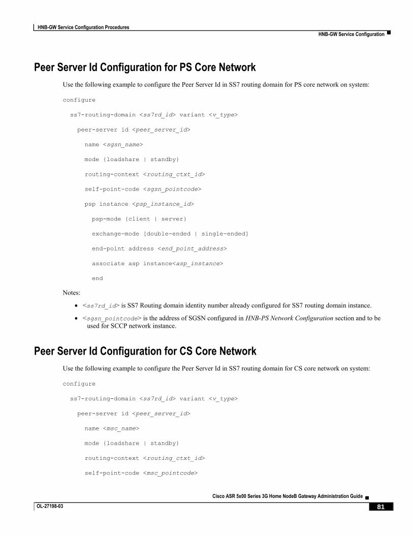
HNB-GW Service Configuration Procedures
HNB-GW Service Configuration ▀
Cisco ASR 5x00 Series 3G Home NodeB Gateway Administration Guide ▄ OL-27198-03 81
Peer Server Id Configuration for PS Core Network
Use the following example to configure the Peer Server Id in SS7 routing domain for PS core network on system:
configure
ss7-routing-domain <ss7rd_id> variant <v_type>
peer-server id <peer_server_id>
name <sgsn_name>
mode {loadshare | standby}
routing-context <routing_ctxt_id>
self-point-code <sgsn_pointcode>
psp instance <psp_instance_id>
psp-mode {client | server}
exchange-mode [double-ended | single-ended]
end-point address <end_point_address>
associate asp instance<asp_instance>
end
Notes:
<ss7rd_id> is SS7 Routing domain identity number already configured for SS7 routing domain instance.
<sgsn_pointcode> is the address of SGSN configured in HNB-PS Network Configuration section and to be
used for SCCP network instance.
Peer Server Id Configuration for CS Core Network
Use the following example to configure the Peer Server Id in SS7 routing domain for CS core network on system:
configure
ss7-routing-domain <ss7rd_id> variant <v_type>
peer-server id <peer_server_id>
name <msc_name>
mode {loadshare | standby}
routing-context <routing_ctxt_id>
self-point-code <msc_pointcode>

HNB-GW Service Configuration Procedures
▀ HNB-GW Service Configuration
▄ Cisco ASR 5x00 Series 3G Home NodeB Gateway Administration Guide
82 OL-27198-03
psp instance <psp_instance_id>
psp-mode {client | server}
exchange-mode [double-ended | single-ended]
end-point address <end_point_address>
associate asp instance <asp_instance>
end
Notes:
<ss7rd_id> is SS7 Routing domain identity number already configured for SS7 routing domain instance.
<msc_pointcode> is the address of MSC configured in HNB-CS Network Configuration section and to be used
for SCCP network instance.
SCCP Network Instance Configuration
Use the following example to configure the SCCP network instance to be associated with HNB-GW service on system:
configure
sccp-network <sccp_id> variant <v_type> -noconfirm
self-point-code <ss7_pointcode>
associate ss7-routing-domain <ss7rd_id>
destination dpc <sgsn_pointcode> name <dpc_route_name>
destination dpc <sgsn_pointcode> version <sccp_variant>
destination dpc <sgsn_pointcode> ssn <dest_subsystem_num>
destination dpc <msc_pointcode> name <dpc_route_name>
destination dpc <msc_pointcode> version <sccp_variant>
destination dpc <msc_pointcode> ssn <dest_subsystem_num>
end
Notes:
<sccp_id> is SCCP network identifier to be associated with HNB-GW.
<v_type> is type of variant to be used for SCCP network instance.
<sgsn_pointcode> is the address of SGSN configured in HNB-PS Network Configuration section and to be
used for SCCP network instance.
<msc_pointcode> is the address of MSC configured in HNB-CS Network Configuration section and to be used
for SCCP network instance.

HNB-GW Service Configuration Procedures
HNB-GW Service Configuration ▀
Cisco ASR 5x00 Series 3G Home NodeB Gateway Administration Guide ▄ OL-27198-03 83
HNB-PS Network Configuration
Use following example to configure the packet switched network parameters at system level to support HNB-GW
service on system:
configure
ps-network <ps_network_name> -noconfirm
global-rnc-id mcc <mcc_num> mnc <mnc_num> id <rnc_id>
ranap reset {ack-timeout <timer_value> | guard-timeout <g_timer> | hnbgw-initiated |
max-retransmissions <retries>}
associate sccp-network <sccp_network_id>
associate gtpu-service <gtpu_ps_svc_name> context <dest_ctxt_name>
sgsn point-code <sgsn_point_code>
no sgsn deadtime
map core-network-id cn_id point-code <sgsn_point_code>
end
Notes:
<ps_network_name> is name of the packet switched network used with HNB-GW for IuPS session.
<sgsn_point_code> is address of the SGSN in SS7 point code format to be used for packet switched traffic
through HNB-GW.
<gtpu_svc_name> is name of the GTP-U service configured in <gtpu_ctxt_name> to provide GTP-U tunnel
over IuPS interface for packet switched traffic towards PS-CN.
HNB-CS Network Configuration
Use following example to configure the circuit switched network parameters at system level to support HNB-GW
service on system:
configure
cs-network <cs_network_name> -noconfirm
global-rnc-id mcc <mcc_num> mnc <mnc_num> id <rnc_id>
ranap reset {ack-timeout <timer_value> | guard-timeout <g_timer> | hnbgw-initiated |
max-retransmissions <retries>}
associate rtp-pool <cs_ip_pool_name> context <dest_ctxt_name>
associate sccp-network <sccp_network_id>
msc point-code <msc_point_code>

HNB-GW Service Configuration Procedures
▀ HNB-GW Service Configuration
▄ Cisco ASR 5x00 Series 3G Home NodeB Gateway Administration Guide
84 OL-27198-03
no msc deadtime
map core-network-id cn_id point-code <msc_point_code>
end
Notes:
<cs_network_name> is name of the HNB-CS Network used with HNB-GW for IuPS session.
<msc_point_code> is address of the MSC in SS7 point code format to be used for circuit switched call
through HNB-GW.
<cs_ip_pool_name> is name of the IP pool configured in destination context named <dest_ctxt_name> to
allocate RTP end point address in this CS network over IuCS interface.
HNB-GW Global Configuration
Use the following example to configure the HNB-GW Global parameters on system to provide global parameters to all
HNB-GW service on a single chassis.
configure
hnbgw-global
access-control-db { imsi-purge-timeout <purge_timeout> | immediate }
tnnsf-timer <timer_value>
sctp alpha-rto <alpha_rto_dur>
sctp beta-rto <beta_rto_dur>
sctp max-retx [init | path | assoc] <max_retry>
sctp max-in-strms <in_strms>
sctp max-out-strms <out_strms>
end
Notes:
Global parameters for HNB-GW services on a chassis are provided through this configuration.
HNB-GW Service Configuration
Use the following example to configure a single of multiple HNB-GW service on system in source context to provide
access to HNBs towards core networks:
configure
sgsn-global

HNB-GW Service Configuration Procedures
HNB-GW Service Configuration ▀
Cisco ASR 5x00 Series 3G Home NodeB Gateway Administration Guide ▄ OL-27198-03 85
aggregate-ipc-msg { linkmgr | sessmgr } { flush-frequency frequency | num-msgs
number_msgs }
exit
context <vpn_ctxt_name>
hnbgw-service <hnbgw_svc_name> -noconfirm
sctp bind address <ip_address>
sctp bind port <sctp_port>
rtp mux
rtcp report interval <dur>
associate rtp-pool <ip_pool_name>
associate gtpu-service <gtpu_iuh_svc_name>
no handin cn-domain cs
radio-network-plmn mcc <mcc> mnc <mnc_code>
rnc-id <rnc_id>
end
Notes:
aggregate-ipc-msg is an optional command supplied through SGSN Global Configuration mode and used to
reduce the latency of IPC messages in SessMgr or LinkMgr towards CN. For more information, refer
Performance Improvement Commands section in Troubleshooting the Service chapter of this guide.
<vpn_ctxt_name> is name of the source context in which HNB-GW service is configured.
<hnbgw_svc_name> is name of the HNB-GW service which is to be configured for used for Iuh reference
between HNB-GW and HNB. Multiple HNB-GW service can be configured in a single or multiple context on a
single chassis.
<ip_address> is the SCTP IP address on which is HNB will communicate with HNB-GW and has
characteristics of Iuh interface.
<gtpu_iuh_svc_name> is name of the GTP-U service configured in <vpn_ctxt_name> to provide GTP-U
tunnel over Iuh interface towards HNB.
<ip_pool_name> is name of the IP pool configured in source context named <vpn_ctxt_name> to allocate
RTP end point address to session manager instance in HNB-GW service over Iuh interface.
rtcp report interval <dur> command configures the generation of RTCP packet/ report types on a per
HNB-GW service instance basis and sets the specified time interval <dur> in seconds between two
consecutive RTCP reports.
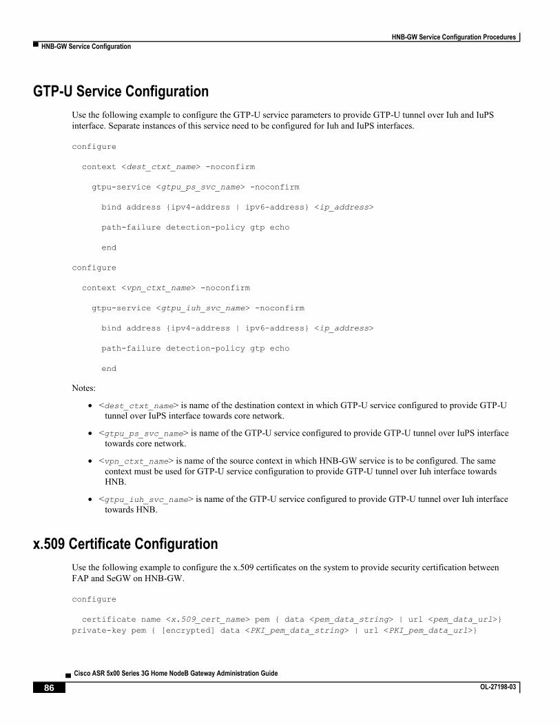
HNB-GW Service Configuration Procedures
▀ HNB-GW Service Configuration
▄ Cisco ASR 5x00 Series 3G Home NodeB Gateway Administration Guide
86 OL-27198-03
GTP-U Service Configuration
Use the following example to configure the GTP-U service parameters to provide GTP-U tunnel over Iuh and IuPS
interface. Separate instances of this service need to be configured for Iuh and IuPS interfaces.
configure
context <dest_ctxt_name> -noconfirm
gtpu-service <gtpu_ps_svc_name> -noconfirm
bind address {ipv4-address | ipv6-address} <ip_address>
path-failure detection-policy gtp echo
end
configure
context <vpn_ctxt_name> -noconfirm
gtpu-service <gtpu_iuh_svc_name> -noconfirm
bind address {ipv4-address | ipv6-address} <ip_address>
path-failure detection-policy gtp echo
end
Notes:
<dest_ctxt_name> is name of the destination context in which GTP-U service configured to provide GTP-U
tunnel over IuPS interface towards core network.
<gtpu_ps_svc_name> is name of the GTP-U service configured to provide GTP-U tunnel over IuPS interface
towards core network.
<vpn_ctxt_name> is name of the source context in which HNB-GW service is to be configured. The same
context must be used for GTP-U service configuration to provide GTP-U tunnel over Iuh interface towards
HNB.
<gtpu_iuh_svc_name> is name of the GTP-U service configured to provide GTP-U tunnel over Iuh interface
towards HNB.
x.509 Certificate Configuration
Use the following example to configure the x.509 certificates on the system to provide security certification between
FAP and SeGW on HNB-GW.
configure
certificate name <x.509_cert_name> pem { data <pem_data_string> | url <pem_data_url>}
private-key pem { [encrypted] data <PKI_pem_data_string> | url <PKI_pem_data_url>}

HNB-GW Service Configuration Procedures
HNB-GW Service Configuration ▀
Cisco ASR 5x00 Series 3G Home NodeB Gateway Administration Guide ▄ OL-27198-03 87
ca-certificate name <ca_root_cert_name> pem { data <pem_data_string> | url
<pem_data_url>}
exit
crypto template <segw_crypto_template> ikev2-dynamic
authentication local certificate
authentication remote certificate
keepalive interval <dur> timeout <dur_timeout>
certificate <x.509_cert_name>
ca-certificate list ca-cert-name <ca_root_cert_name>
payload <crypto_payload_name> match childsa [match {ipv4 | ipv6}]
ip-address-alloc dynamic
ipsec transform-setlist <ipsec_trans_set>
end
configure
context <vpn_ctxt_name>
subscriber default
ip context-name <vpn_ctxt_name>
ip address pool name <ip_pool_name>
end
Notes:
<vpn_ctxt_name> is name of the source context in which HNB-GW service is configured.
<x.509_cert_name> is name of the x.509 certificate where PEM data <pem_data_string> and PKI
<PKI_pem_data_string> is configured.
<ca_root_cert_name> is name of the CA root certificate where PEM data <pem_data_string> is
configured for CPE.
Security Gateway and Crypto map Template Configuration
Use the following example to configure the IPsec profile and Crypto map template enabling SeGW on HNB-GW for
IPsec tunneling.
configure
context <vpn_ctxt_name>

HNB-GW Service Configuration Procedures
▀ HNB-GW Service Configuration
▄ Cisco ASR 5x00 Series 3G Home NodeB Gateway Administration Guide
88 OL-27198-03
eap-profile <eap_prof_name>
mode authentication-pass-through
exit
ip pool ipsec <ip_address> <subnetmask>
ipsec transform-set <ipsec_trans_set>
exit
ikev2 transform-set <ikev2_trans_set>
exit
crypto template <crypto_template>
authentication eap-profile <eap_prof_name>
exit
ikev2-ikesa transform-set list <ikev2_trans_set>
payload <crypto_payload_name> match childsa [match {ipv4 | ipv6}]
ip-address-alloc dynamic
ipsec transform-setlist <ipsec_trans_set>
exit
ikev2-ikesa keepalive-user-activity
end
configure
context <vpn_ctxt_name>
hnbgw-service <hnbgw_svc_name>
security-gateway bind address <segw_ip_address> crypto-template <crypto_template>
context <segw_ctxt_name>
end
Notes:
<vpn_ctxt_name> is name of the source context in which HNB-GW service is configured.
<segw_ctxt_name> is name of the context in which Se-GW service is configured. By default it takes context
where HNB-GW service is configured.
<hnbgw_svc_name> is name of the HNB-GW service which is to be configured for used for Iuh reference
between HNB-GW and HNB.

HNB-GW Service Configuration Procedures
HNB-GW Service Configuration ▀
Cisco ASR 5x00 Series 3G Home NodeB Gateway Administration Guide ▄ OL-27198-03 89
Multiple MSC Selection without Iu-Flex Configuration
Use the following example to configure the multiple MSC selection over IuCS interface for MSC pooling and sharing.
configure
cs-network <cs_network_name>
associate sccp-network <sccp_network_id>
map lac range <lac_start> to <lac_end> point-code <msc_point_code>
end
Notes:
<cs_network_name> is name of the HNB-CS network which is already configured and associated with HNB-
GW service.
<sccp_network_id> is the identifier used for the SCCP network which is already configured and associated
with HNB-CS Network <cs_network_name>.
LAC value must be an integer between 0 and 65535.
Open Access Mode Configuration
Use the following example to configure the Open Access Mode for open HNBs in an HNB-GW service instance. It also
includes the paging optimization configuration for open HNBs.
configure
context <vpn_ctxt_name>
hnbgw-service <hnbgw_svc_name> -noconfirm
hnb-access-mode open max-registered-ue <reg_ue>
end
configure
hnbgw-global
paging open-hnb [ hnb-where-ue-registered fallback ] {always | never | only-if-with-
paging-area}
end
Notes:
<vpn_ctxt_name> is name of the source context in which HNB-GW service is configured.
<hnbgw_svc_name> is name of the HNB-GW service in which Open Access mode support is to be configured.
<reg_ue> is number of the UEs allowed to be registered through any Open HNB in Open Access Mode
support. By default 16 UEs are allowed.

HNB-GW Service Configuration Procedures
▀ HNB-GW Service Configuration
▄ Cisco ASR 5x00 Series 3G Home NodeB Gateway Administration Guide
90 OL-27198-03
Hybrid Access Mode Configuration
Use the following example to configure the Hybrid Access Mode for hybrid HNBs in an HNB-GW service instance. It
also includes the paging optimization configuration for hybrid HNBs.
configure
context <vpn_ctxt_name>
hnbgw-service <hnbgw_svc_name> -noconfirm
hnb-access-mode hybrid max-non-access-controlled-ue <reg_ue_hyb>
hnb-access-mode mismatch-action { accept-aaa-value | hnb-reg-rej }
end
configure
hnbgw-global
paging open-hnb [ hnb-where-ue-registered fallback ] {always | never | only-if-with-
paging-area}
hybrid-hnb [ hnb-where-ue-registered [ hnbs-having-imsi-in-whitelist fallback [ always
| never | only-if-with-paging-area ] | fallback [always | never |only-if-with-paging-
area]]| hnbs-having-imsi-in-whitelist fallback [always | never |only-if-with-paging-area]
| always | never | only-if-with-paging-area ]
end
Notes:
<vpn_ctxt_name> is name of the source context in which HNB-GW service is configured.
<hnbgw_svc_name> is name of the HNB-GW service in which Open Access mode support is to be configured.
<reg_ue_hyb> is number of the UEs allowed to be registered through any Hybrid HNB in Hybrid Access
Mode support. By default 16 UEs are allowed.
CBS Configuration
Use the following example to configure the cell broadcasting service for open, close, and hybrid HNBs in an HNB-GW
service instance. Up to 16 HNB-GW services can be associated with a CBS service.
configure
context <ctxt_name>
cbs-service <cbs_svc_name>
bind address <ip_address>
cbc-server address <cbc_ip_address>

HNB-GW Service Configuration Procedures
HNB-GW Service Configuration ▀
Cisco ASR 5x00 Series 3G Home NodeB Gateway Administration Guide ▄ OL-27198-03 91
sabp timer <timer_in_secs>
end
configure
context <ctxt_name>
hnbgw-service <hnbgw_svc_name> -noconfirm
associate cbs-service <cbs_svc_name>
end
Notes:
<ctxt_name> is name of the source context in which HNB-GW service is configured.
<hnbgw_svc_name> is name of the HNB-GW service in which Open Access mode support is to be configured.
<ip_address> is the IPv4 type IP address of CBS service.
<cbc_ip_address> is the IPv4 type IP address of CBC server.
<timer_in_secs> is the SABP timer which is the wait time for receiving the SABP response from a peer. It is
an integer value between 1 and 300. If not configured, the default value for this timer is taken as 10 seconds.
Verifying HNB-GW Configuration
This section shows the configuration parameters configured for HNB-GW service.
Step 1 Verify that your HNB-GW services were created and configured properly by entering the following command in Exec
Mode:
show hnbgw-service hnbgw-service <hnbgw_svc_name>}
The output of this command displays concise listing of HNB-GW service parameter settings as configured on
system.
Step 2 Verify configuration errors of your HNB-GW services by entering the following command in Exec Mode:
show configuration errors section hnbgw-service}
The output of this command displays current configuration errors and warning information for the target
configuration file as specified for HNB-GW service

HNB-GW Service Configuration Procedures
▀ DSCP Marking Configuration
▄ Cisco ASR 5x00 Series 3G Home NodeB Gateway Administration Guide
92 OL-27198-03
DSCP Marking Configuration To configure DSCP marking for control and data packet over Iuh and Iu interface for HNB-GW service:
Step 1 Modify HNB-GW service to configure the DSCP marking for SCTP and UDP packets over Iuh interface by applying
the example configuration in the Configuring DSCP Marking over Iuh Interface section.
Step 2 Modify HNB-GW service to configure the DSCP marking for UDP packets over Iu interface by applying the example
configuration in the Configuring DSCP Marking for Data Packet over Iu Interface section.
Step 3 Modify SGSN-Global configuration to create the DSCP template for SCTP packets and modify PSP Instance to
associate this DSCP template for downlink packets with particular PSP intance by applying the example configuration
in the Creating and Associating DSCP Template for Control Packets over Iu Interface section.
Step 4 Save your configuration to flash memory, an external memory device, and/or a network location using the Exec mode
command save configuration. For additional information on how to verify and save configuration files, refer to the
System Administration Guide and the Command Line Interface Reference.
Configuring DSCP Marking over Iuh Interface
To configure the DSCP marking over Iuh interface for SCTP and UDP packets modify the HNB-GW service by
applying the following example configuration:
configure
context <vpn_ctxt_name>
hnbgw-service <hnbgw_svc_name> -noconfirm
ip iuh-qos-dscp protocol { sctp | udp } payload { all | gtpu | rtcp | rtp } { af11
| af12 | af13 | af21 | af22 | af23 | af31 | af32 | af33 | af41 | af42 | af43 | be | cs1 |
cs2 | cs3 | cs4 | cs5 | cs6 | cs7 | ef }
end
Notes:
<vpn_ctxt_name> is name of the source context in which HNB-GW service is configured.
<hnbgw_svc_name> is name of the HNB-GW service in which Open Access mode support is to be configured.
For more commands and keyword options, refer Command Line Interface Reference.
Configuring DSCP Marking for Data Packet over Iu Interface
To configure the DSCP marking over Iu interface for UDP packets modify the HNB-GW service by applying the
following example configuration:
configure
context <vpn_ctxt_name>

HNB-GW Service Configuration Procedures
DSCP Marking Configuration ▀
Cisco ASR 5x00 Series 3G Home NodeB Gateway Administration Guide ▄ OL-27198-03 93
hnbgw-service <hnbgw_svc_name> -noconfirm
ip iu-qos-dscp protocol udp payload { all | gtpu | rtcp | rtp } { af11 | af12 |
af13 | af21 | af22 | af23 | af31 | af32 | af33 | af41 | af42 | af43 | be | cs1 | cs2 |
cs3 | cs4 | cs5 | cs6 | cs7 | ef }
end
Notes:
<vpn_ctxt_name> is name of the source context in which HNB-GW service is configured.
<hnbgw_svc_name> is name of the HNB-GW service in which Open Access mode support is to be configured.
For more commands and keyword options, refer Command Line Interface Reference.
Creating and Associating DSCP Template for Control Packets over Iu Interface
To create a DSCP template and associating it with particular PSP instance for SCTP packets over Iu interface modify
the SGSN Gloal and PSP instance Configuration mode by applying the following example configuration:
configure
sgsn-global
dscp-template <sctp_dscp_template> -noconfirm
control-packet qos-dscp { af11 | af12 | af13 | af21 | af22 | af23 | af31 | af32 |
af33 | af41 | af42 | af43 | be | cs1 | cs2 | cs3 | cs4 | cs5 | cs6 | cs7 | ef }
end
configure
ss7-routing-domain <ss7rd_id> variant <v_type>
peer-server id <peer_server_id>
psp instance <psp_instance_id>
associate dscp-template downlink <sctp_dscp_template>
Notes:
<ss7rd_id> is pre-configured SS7 Routing Domain instance for HNB-GW service.
<peer_server_id> is pre-configured Peer server id configured in SS7 Routing Domain instance for HNB-GW
service.
<psp_instance_id> is pre-configured PSP instance id configured for Peer-Server id in SS7 Routing Domain
instance for HNB-GW service.
<sctp_dscp_template> is the DSCP tempate created in SGSN Global mode for SCTP DSCP marking and
associated with PSP instance in SS7 Routing Domain instance for HNB-GW service.

HNB-GW Service Configuration Procedures
▀ DHCP Configuration
▄ Cisco ASR 5x00 Series 3G Home NodeB Gateway Administration Guide
94 OL-27198-03
DHCP Configuration To configure DHCP Proxy interface support on chassis for HNB-GW service:
Step 1 Create a DHCP service specific to HNB-GW service by applying the example configuration in the Configuring DHCP
Service section.
Step 2 Create a subscriber template for HNB clients sesssion and associate the DHCP service with created subscriber template
by applying the example configuration in the Configuring Subscriber Template for HNB section.
Step 3 Save your configuration to flash memory, an external memory device, and/or a network location using the Exec mode
command save configuration. For additional information on how to verify and save configuration files, refer to the
System Administration Guide and the Command Line Interface Reference.
Configuring DHCP Service
Configure a DHCP service for DHCP interface support in the HNB-GW service by applying the following example
configuration:
configure
context <vpn_ctxt_name>
dhcp-service <dhcp_svc_name> -noconfirm
dhcp client-identifier ike-id
dhcp server selection-algorithm use-all
dhcp server <dhcp_server_ip>
dhcp server port 61610
end
Notes:
<vpn_ctxt_name> is name of the source context in which HNB-GW service is configured.
<dhcp_svc_name> is name of the DHCP service configured in Context Configuration mode for DHCP
interface support in HNB-GW service.
<dhcp_server_ip> IP address of the DHCP server associated with DHCP service for DHCP interface support
in HNB-GW service.
For more commands and keyword options, refer Command Line Interface Reference.
Configuring Subscriber Template for HNB
Configure the subscriber template to associate the DHCP service for HNB clients by applying the following example
configuration:

HNB-GW Service Configuration Procedures
DHCP Configuration ▀
Cisco ASR 5x00 Series 3G Home NodeB Gateway Administration Guide ▄ OL-27198-03 95
configure
context <vpn_ctxt_name>
subscriber default
dhcp service <dhcp_svc_name> context <vpn_ctxt_name>
end
Notes:
<vpn_ctxt_name> is name of the source context in which DHCP service is configured.
<dhcp_svc_name> is name of the pre-configured DHCP service configured in Context Configuration mode for
DHCP interface support in HNB-GW service.
For more commands and keyword options, refer Command Line Interface Reference.

HNB-GW Service Configuration Procedures
▀ IuCS over ATM Configuration
▄ Cisco ASR 5x00 Series 3G Home NodeB Gateway Administration Guide
96 OL-27198-03
IuCS over ATM Configuration To configure IuCS-over-ATM on HNB-GW service:
Step 1 Configure and activate the SONET card by applying the example configuration in the Configuring the SONET Card
section.
Step 2 Modify the configured SS7 Routing Domain configuration with Linkset Id and ATM parameters by applying the
example configuration in the Configuring Linkset Id and ATM Parameters section.
Step 3 Configure ALCAP service and AAL2 node parameters by applying the example configuration in the Configuring
ALCAP Service and AAL2 Node section.
Step 4 Configure the ATM port and PVC for AAL2 and AAL5 type of PVC by applying the example configuration in the
Configuring the ATM Port section.
Step 5 Modify the configured HNB-CS Network service configuration to associate ALCAP service for IuCS-over-ATM
support by applying the example configuration in the Associating ALCAP Service with HNB-CS Network Service
section.
Step 6 Save your configuration to flash memory, an external memory device, and/or a network location using the Exec mode
command save configuration. For additional information on how to verify and save configuration files, refer to the
System Administration Guide and the Command Line Interface Reference.
Configuring the SONET Card
To configure a SONET card for IuCS-over-ATM facility, apply the following example configuration:
configure
card <sonet_card_num>
framing {sonet | SDH}
no shutdown
end
Notes:
For other configuration procedures of ATM card, refer Creating and Configuring ATM Interfaces and Ports
section in System Administration Guide.
For more commands and keyword options, refer Command Line Interface Reference.
Configuring Linkset Id and ATM Parameters
To configure the linkset id and ATM parameters you need to modify existing SS7 Routing domain configuration by
applying the following example:
configure

HNB-GW Service Configuration Procedures
IuCS over ATM Configuration ▀
Cisco ASR 5x00 Series 3G Home NodeB Gateway Administration Guide ▄ OL-27198-03 97
ss7-routing-domain <ss7rd_id> variant <v_type>
ssf {international | national | reserved | spare}
linkset id <linkset_id>
self-point-code <self_pointcode>
adjacent-point-code <adj_pointcode>
link id <link_id> link-type atm-broadband
priority <link_priority_value>
signaling-link-code <sig_link_code>
exit
exit
route destination-point-code <rd_pointcode> linkset-id <linkset_id>
end
Notes:
<ss7rd_id> is pre-configured SS7 Routing Domain instance configured at the system level to provide IuCS-
over-ATM support to HNB-GW service.
Configuring ALCAP Service and AAL2 Node
To configure the ALCAP service with AAL2 node a nd AAL2 path parameters apply the following example:
configure
context <alcap_ctxt_name>
alcap-service <alcap_svc_name> -noconfirm
associate ss7-routing-domain <ss7rd_id>
self-point-code <alcap_pointcode>
aal2-route endpoint <AESA_route_endpoint> aal2-node <aal2_node_name>
aal2-node <aal2_node_name>
point-code <aal2_pointcode>
aal2-path-id <aal2_path_id> [block]
end
Notes:

HNB-GW Service Configuration Procedures
▀ IuCS over ATM Configuration
▄ Cisco ASR 5x00 Series 3G Home NodeB Gateway Administration Guide
98 OL-27198-03
<alcap_ctxt_name> is name of the context in which ALCAP service is configured.
<alcap_svc_name> is name of the ALCAP service which is to be configured for IuCS-over-ATM between
HNB-GW and CS core network.
<ss7rd_id> is a pre-configured SS7 routing domain instance.
<alcap_pointcode> is address of the ALCAP node in SS7 point code notation.
Configuring the ATM Port
To configure ATM port for IuCS-over-ATM facility, apply the following example configuration:
configure
port atm <sonet_card_num>/<port_num>
no shutdown
pvc vpi <vpi_num> vci <aal5_vci_num> type aal5
no shutdown
bind link ss7-routing-domain <ss7rd_id> linkset-id <linkset_id> link-id <link_id>
exit
pvc vpi <vpi_num> vci <aal2_vci_num> type aal2 cps-payload-size <cps_paylod_size>
no shutdown
bind alcap-service <alcap_svc_name> context <alcap_ctxt_name> aal2-node
<aal2_node_name> aal2-path <aal2_path_id>
end
Notes:
<alcap_ctxt_name> is name of the context in which ALCAP service is configured.
<alcap_svc_name> is name of the pre-configured ALCAP service which is bound to ATM port for IuCS-over-
ATM between HNB-GW and CS core network.
<aal2_node_name> is a pre-configured AAL2 node in ALCAP Service Configuration mode.
<aal2_path_id> is a pre-configured identifier for AAL2 path in AAL2 Node Configuration mode.
Associating ALCAP Service with HNB-CS Network Service
To associate a pre-configured ALCAP service with HNB-CS Network Service for IuCS-over-ATM function, apply the
following example configuration:
configure
cs-network <cs_network_name>

HNB-GW Service Configuration Procedures
IuCS over ATM Configuration ▀
Cisco ASR 5x00 Series 3G Home NodeB Gateway Administration Guide ▄ OL-27198-03 99
associate alcap-service <alcap_svc_name> context <alcap_ctxt_name>
end
Notes:
<cs_network_name> is a pre-configured HNB-CS Network service associated with HNB-GW for CS session.
<alcap_svc_name> is name of the ALCAP service configured in destination context named
<alcap_ctxt_name> to provide IuCS over ATM support through this CS network.

HNB-GW Service Configuration Procedures
▀ Iu-Flex Configuration
▄ Cisco ASR 5x00 Series 3G Home NodeB Gateway Administration Guide
100 OL-27198-03
Iu-Flex Configuration To configure Iu-Flex support on HNB-GW service:
Step 1 Modify the configured HNB-CS Network configuration with Iu-Flex parameters by applying the example configuration
in the Iu-Flex over IuCS Interface Configuration section.
Step 2 Modify the configured HNB-PS Network configuration with Iu-Flex parameters by applying the example configuration
in the Iu-Flex over IuPS Interface Configuration section.
Step 3 Save your configuration to flash memory, an external memory device, and/or a network location using the Exec mode
command save configuration. For additional information on how to verify and save configuration files, refer to the
System Administration Guide and the Command Line Interface Reference.
Iu-Flex over IuCS Interface Configuration
Use the following example to configure the Iu-Flex feature over IuCS interface for MSC pooling and sharing.
configure
cs-network <cs_network_name>
map idnns range <idnns_start> to <idnns_end> point-code <msc_point_code> [ backup
point-code <bkup_msc_point_code>]
map nri range <nri_start> to <nri_end> point-code <msc_point_code>
nri length <nri_value>
null-nri <null_nri_value>
offload-msc point-code <msc_point_code>
end
Notes:
<cs_network_name> is name of the HNB-CS network which is already configured and associated with HNB-
GW service.
<nri_value> must be an integer between 1 and 10. A zero NRI length value disables the Iu-Flex feature on
HNB-GW service.
offload-msc point-code <msc_point_code> command enables the exclusion of specific primary MSC
during NAS Node Selection Function (NNSF) procedure when it needs to be off-loaded while using Iu-Flex
functionality on HNB-GW node.
Important: Offload check is only for the primary point code and NOT for the backup point code. This command
can be used for planned maintenance as well.

HNB-GW Service Configuration Procedures
Iu-Flex Configuration ▀
Cisco ASR 5x00 Series 3G Home NodeB Gateway Administration Guide ▄ OL-27198-03 101
Iu-Flex over IuPS Interface Configuration
Use the following example to configure the Iu-Flex feature over IuPS interface for SGSN pooling and sharing.
configure
ps-network <ps_network_name>
map idnns range <idnns_start> to <idnns_end> point-code <sgsn_point_code> [ backup
point-code <bkup_sgsn_point_code>]
map nri range <nri_start> to <nri_end> point-code <sgsn_point_code>
nri length <nri_value>
null-nri <null_nri_value>
offload-sgsn point-code <sgsn_point_code>
end
Notes:
<sgsn_network_name> is name of the HNB-PS network which is already configured and associated with
HNB-GW service.
<nri_value> must be an integer between 1 and 10. A zero NRI length value disables the Iu-Flex feature on
HNB-GW service.
offload-sgsn point-code <sgsn_point_code> command enables the exclusion of specific primary
SGSN during NAS Node Selection Function (NNSF) procedure when it needs to be off-loaded while using Iu-
Flex functionality on HNB-GW node.
Important: Offload check is only for the primary point code and NOT for the backup point code. This command
can be used for planned maintenance as well.

HNB-GW Service Configuration Procedures
▀ Logging Facility Configuration
▄ Cisco ASR 5x00 Series 3G Home NodeB Gateway Administration Guide
102 OL-27198-03
Logging Facility Configuration Use the following example to configure the HNB-GW system to enable the logging and debug facilities for HNB-GW
subscriber and related protocols.
Important: This section provides the minimum instruction set for configuring logging facilities for
system monitoring that allows the user to monitor the events and logging. Commands that configure
additional logging facilities are provided in the Exec Mode Command chapter of Command Line Interface
Reference.
configure
logging console
logging display event-verbosity {min | concise | full}
logging filter runtime facility aal2 { critical | error | warning | unusual | info |
trace | debug }
logging filter runtime facility alcap { critical | error | warning | unusual | info |
trace | debug }
logging filter runtime facility alcapmgr { critical | error | warning | unusual | info
| trace | debug }
logging filter runtime facility diameter { critical | error | warning | unusual | info
| trace | debug }
logging filter runtime facility hnb-gw { critical | error | warning | unusual | info |
trace | debug }
logging filter runtime facility hnbmgr { critical | error | warning | unusual | info |
trace | debug }
logging filter runtime facility sccp { critical | error | warning | unusual | info |
trace | debug }
logging filter runtime facility sctp { critical | error | warning | unusual | info |
trace | debug }
logging filter runtime facility threshold { critical | error | warning | unusual | info
| trace | debug }
Important: Refer System Administration Guide for more information on logging facility configuration.
Displaying Logging Facility
This section shows the logging facility event logs for logging facilities enabled on HNB-GW node.

HNB-GW Service Configuration Procedures
Logging Facility Configuration ▀
Cisco ASR 5x00 Series 3G Home NodeB Gateway Administration Guide ▄ OL-27198-03 103
Step 1 Verify the logging facilities configured on HNB-GW system node by entering the following command in Exec Mode:
show logging [ active | verbose]
The output of this command provides the display of event logs for configured logging facilities.

HNB-GW Service Configuration Procedures
▀ Congestion Control Configuration
▄ Cisco ASR 5x00 Series 3G Home NodeB Gateway Administration Guide
104 OL-27198-03
Congestion Control Configuration To configure Congestion Control functionality:
Step 1 Configure Congestion Control Threshold by applying the example configuration in the Configuring the Congestion
Control Threshold section.
Step 2 Configure Service Congestion Policies by applying the example configuration in the Configuring Service Congestion
Policies section.
Step 3 Optional. Operator can configure the system to reject all new incoming calls to specific or all HNB-GW service
instance in a busy-out or planned maintenance or for troubleshooting by applying the example configuration in the
Configuring New Call Policy section.
Step 4 Save your configuration to flash memory, an external memory device, and/or a network location using the Exec mode
command save configuration. For additional information on how to verify and save configuration files, refer to the
System Administration Guide and the Command Line Interface Reference.
Configuring the Congestion Control Threshold
To configure congestion control threshold, apply the following example configuration:
configure
congestion-control threshold max-sessions-per-service-utilization <percent>
congestion-control threshold tolerance <percent>
end
Notes:
There are several additional threshold parameters. See the Global Configuration Mode chapter of the Command
Line Interface Reference for more information.
The tolerance is the percentage under a configured threshold that dictates the point at which the condition is
cleared.
Repeat this configuration as needed for additional thresholds.
Configuring Service Congestion Policies
To create a congestion control policy, apply the following example configuration:
configure
congestion-control policy hnbgw-service action { drop | none | reject }
end
Notes:

HNB-GW Service Configuration Procedures
Congestion Control Configuration ▀
Cisco ASR 5x00 Series 3G Home NodeB Gateway Administration Guide ▄ OL-27198-03 105
For HNB-GW service sessions reject is the default action.
Configuring New Call Policy
To create a new call policy in a busy our or planned maintenance or other operator intervened scenario, apply the
following example configuration:
newcall policy hnbgw-service [all | name <hnbgw_svc_name>] reject
Notes:
For HNB-GW service sessions reject is the default action for all new calls coming on a specific or all HNB-
GW service instance.

HNB-GW Service Configuration Procedures
▀ Alarm and Alert Trap Configuration
▄ Cisco ASR 5x00 Series 3G Home NodeB Gateway Administration Guide
106 OL-27198-03
Alarm and Alert Trap Configuration To enable and configure the SNMP Traps to generate alarms and alerts from system for various events and thresholds in
HNB-GW service, apply the following example configuration:
configure
snmp trap { enable | suppress} [congestion] {ThreshTotalHNBGWHnbSess |
ThreshTotalHNBGWIuSess | ThreshTotalHNBGWUeSess} [ target <trap_collector>]
snmp trap { enable | suppress} {ThreshTotalHNBGWHnbSess | ThreshTotalHNBGWIuSess |
ThreshTotalHNBGWUeSess} [ target <trap_collector>]
snmp trap { enable | suppress} HNBGWALCAPNodeReset [ target <trap_collector>]
snmp trap { enable | suppress} HNBGWALCAPPathBlock [ target <trap_collector>]
snmp trap { enable | suppress} HNBGWALCAPPathReset [ target <trap_collector>]
snmp trap { enable | suppress} HNBGWALCAPPathUnBlock [ target <trap_collector>]
snmp trap { enable | suppress} HNBGWMSCRanapReset [ target <trap_collector>]
snmp trap { enable | suppress} HNBGWSGSNRanapReset [ target <trap_collector>]
snmp trap { enable | suppress} HNBGWServiceStart [ target <trap_collector>]
snmp trap { enable | suppress} HNBGWServiceStop [ target <trap_collector>]
snmp trap { enable | suppress} HNBGWServiceStop [ target <trap_collector>]
end
Notes:
There are several additional SNMP Traps which can be configured. Refer Global Configuration Mode chapter of
the Command Line Interface Reference for more information.
For more information on SNMP Traps, refer System SNMP-MIB Reference.
Repeat this configuration as needed for additional traps.

HNB-GW Service Configuration Procedures
SNMP-MIB Traps for HNB-GW Service ▀
Cisco ASR 5x00 Series 3G Home NodeB Gateway Administration Guide ▄ OL-27198-03 107
SNMP-MIB Traps for HNB-GW Service SNMP traps are used to manage and monitor the service on HNB-GW node.
Supported SNMP traps and its id are indicated in the following table.
Table 5. SNMP Traps and Object Ids
Traps Object Id
starThreshHNBGWHnbSess starentTraps 484
starThreshClearHNBGWHnbSess starentTraps 485
starThreshHNBGWUeSess starentTraps 486
starThreshClearHNBGWUeSess starentTraps 487
starThreshHNBGWIuSess starentTraps 488
starThreshClearHNBGWIuSess starentTraps 489
starHNBGWSGSNRanapReset starentTraps 1155
starHNBGWMSCRanapReset starentTraps 1156
starALCAPNodeReset starentTraps 1157
starALCAPPathReset starentTraps 1158
starALCAPBlock starentTraps 1159
starALCAPUnBlock starentTraps 1160
Important: For more information on SNMP trap configuration and supported object ids, refer System SNMP-
MIB Reference.
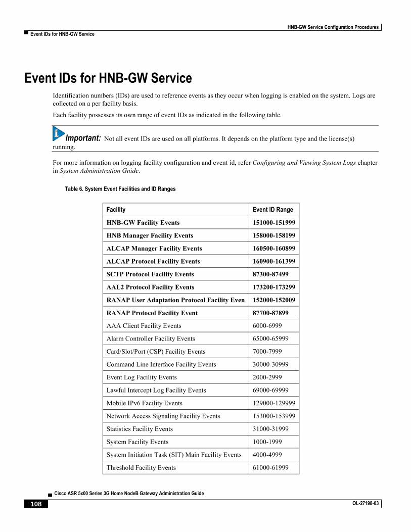
HNB-GW Service Configuration Procedures
▀ Event IDs for HNB-GW Service
▄ Cisco ASR 5x00 Series 3G Home NodeB Gateway Administration Guide
108 OL-27198-03
Event IDs for HNB-GW Service Identification numbers (IDs) are used to reference events as they occur when logging is enabled on the system. Logs are
collected on a per facility basis.
Each facility possesses its own range of event IDs as indicated in the following table.
Important: Not all event IDs are used on all platforms. It depends on the platform type and the license(s)
running.
For more information on logging facility configuration and event id, refer Configuring and Viewing System Logs chapter
in System Administration Guide.
Table 6. System Event Facilities and ID Ranges
Facility Event ID Range
HNB-GW Facility Events 151000-151999
HNB Manager Facility Events 158000-158199
ALCAP Manager Facility Events 160500-160899
ALCAP Protocol Facility Events 160900-161399
SCTP Protocol Facility Events 87300-87499
AAL2 Protocol Facility Events 173200-173299
RANAP User Adaptation Protocol Facility Even 152000-152009
RANAP Protocol Facility Event 87700-87899
AAA Client Facility Events 6000-6999
Alarm Controller Facility Events 65000-65999
Card/Slot/Port (CSP) Facility Events 7000-7999
Command Line Interface Facility Events 30000-30999
Event Log Facility Events 2000-2999
Lawful Intercept Log Facility Events 69000-69999
Mobile IPv6 Facility Events 129000-129999
Network Access Signaling Facility Events 153000-153999
Statistics Facility Events 31000-31999
System Facility Events 1000-1999
System Initiation Task (SIT) Main Facility Events 4000-4999
Threshold Facility Events 61000-61999

HNB-GW Service Configuration Procedures
Event IDs for HNB-GW Service ▀
Cisco ASR 5x00 Series 3G Home NodeB Gateway Administration Guide ▄ OL-27198-03 109
Facility Event ID Range
Virtual Private Network Facility Events 5000-5999


Cisco ASR 5x00 Series 3G Home NodeB Gateway Administration Guide ▄ OL-27198-03 111
Chapter 4 Monitoring the Service
This chapter provides information for monitoring service status and performance using the show commands found in
the Command Line Interface (CLI). These command have many related keywords that allow them to provide useful
information on all aspects of the system ranging from current software configuration through call activity and status.
The selection of keywords described in this chapter is intended to provided the most useful and in-depth information for
monitoring the system. For additional information on these and other show command keywords, refer to the Command
Line Interface Reference.
In addition to the CLI, the system supports the sending of Simple Network Management Protocol (SNMP) traps that
indicate status and alarm conditions. Refer to the SNMP MIB Reference Guide for a detailed listing of these traps.

Monitoring the Service
▀ Monitoring System Status and Performance
▄ Cisco ASR 5x00 Series 3G Home NodeB Gateway Administration Guide
112 OL-27198-03
Monitoring System Status and Performance This section contains commands used to monitor the status of tasks, managers, applications and other software
components in the system. Output descriptions for most of the commands are located in the Counters and Statistics
Reference.
Table 7. System Status and Performance Monitoring Commands
To do this: Enter this command:
View HNB-GW Service Information
View HNB-GW services running on chassis show hnbgw session all
View summary of HNB-GW sessions running on chassis show hnbgw session summary
View detailed information of HNB-GW sessions show hnbgw session full
Monitor HNB-GW Subscriber Session Information
Monitor HNB-GW subscribers by call identifier monitor subscriber callid call_id
Monitor HNB-GW subscribers by user name identifier monitor subscriber usernamesubscriber_name
Monitor HNB-GW subscribers by IMSI value monitor subscriber imsiimsi
Monitor HNB-GW subscribers by IP address of UE monitor subscriber ipaddripv4_address
Monitoring HNB and UE by Protocol Monitoring
Monitor HNB through Protocol Monitoring monitor protocol Use following protocol options for HNB monitoring:
SCTP
HNBAP
RUA
RADIUS-AUTH
RADIUS-COA

Monitoring the Service
Monitoring System Status and Performance ▀
Cisco ASR 5x00 Series 3G Home NodeB Gateway Administration Guide ▄ OL-27198-03 113
To do this: Enter this command:
Monitor UE through Protocol Monitoring monitor protocol Use following protocol options for HNB monitoring:
HNBAP
RUA
RANAP
SCCP
ALCAP
AAL2
GTP-U
RTP
View Subscriber Information
Display Session Resource Status
View session resource status show resources session
Display Subscriber Configuration Information
View locally configured subscriber profile settings (must be in
context where subscriber resides) show subscribers configuration username subscriber_name
View remotely configured subscriber profile settings show subscribers aaa-configuration username subscriber_name
View Subscribers Currently Accessing the System
View a listing of subscribers currently accessing the system show subscribers hnbgw-only all
View information for a specific subscriber show subscribers hnbgw-only full username username
View Subscriber Counters
View counters for a specific subscriber show subscribers counters username subscriber_name
View Recovered Session Information
View session state information and session recovery status show subscriber debug-info { callid | msid |
username }
View Session Statistics and Information
Display Historical Session Counter Information
View all historical information for all sample intervals show session counters historical
Display Session Duration Statistics
View session duration statistics show session duration
Display Session State Statistics

Monitoring the Service
▀ Monitoring System Status and Performance
▄ Cisco ASR 5x00 Series 3G Home NodeB Gateway Administration Guide
114 OL-27198-03
To do this: Enter this command:
View session state statistics show session progress
Display Session Subsystem and Task Statistics Refer to the System Software Task and Subsystem Descriptions appendix of the System Administration Guide for additional
information on the Session subsystem and its various manager tasks.
View GTPU Manager statistics show session subsystem facility gtpumgr all
View HNB-GW Manager statistics show session subsystem facility hnbmgr all
View Session Manager statistics show session subsystem facility sessmgr all
View AAL2 protocol facility statistics show logs facility aal2
View ALCAP service facility statistics show logs facility alcap
View ALCAP Manager facility statistics show logs facility alcapmgr
View HNB-GW Manager facility statistics show logs facility hnb-gw
View HNB Manager facility statistics show logs facility hnbmgr
View GTPU Manager Instance statistics show gtpu statistics gtpumgr-instance gtpu_instance
Display Session Disconnect Reasons
View session disconnect reasons specific to HNB-GW service show hnbgw disconnect-reasons
View session disconnect reasons with verbose output show session disconnect-reasons
View HNB-GW Service Configuration
Display a HNB-GW Service Status
View all configured HNB-GW services configuration in detail show hnbgw-service all verbose
View configuration errors in HNB-GW section in detail show configuration errors section hnbgw-
service verbose
View HNB-GW Related Statistics
View HNB-GW service counters filtered on an HNB-GW service show hnbgw counters hnbgw-service hnb_gw_svc_name
View HNB-GW service counters filtered by an HNB id show hnbgw counters hnbid hnb_identifier
View HNB-GW service statistics filtered on an HNB-GW service show hnbgw statistics hnbgw-service hnbgw_svc_name verbose
View HNB-GW service statistics filtered by an HNB id show hnbgw statistics hnbid hnb_identifier
View GTP-U Service Statistics
View GTP-U peer information show gtpu statistics peer-address ip_address
View GTP-U Service information show gtpu statistics gtpu-service gtpu_svc_name

Monitoring the Service
Monitoring Logging Facility ▀
Cisco ASR 5x00 Series 3G Home NodeB Gateway Administration Guide ▄ OL-27198-03 115
Monitoring Logging Facility This section contains commands used to monitor the logging facility active for specific tasks, managers, applications
and other software components in the system.
Table 8. Logging Facility Monitoring Commands
To do this: Enter this command:
Monitor logging facility for specific session
based on Call-id on system
logging trace callid call_id
Monitor logging facility based on IP address
used in session on system
logging trace ipaddr ip_address
Monitor logging facility based on MS
Identity used in session on system
logging trace msid ms_identifier
Monitor logging facility based on user name
used in session on system
logging trace username name
Monitor AAL2 logging facility on HNB-GW
system
logging filter active facility aal2 { critical | error |
warning | unusual | info | trace | debug }
Monitor Diameter logging facility on HNB-
GW system
logging filter active facility diameter { critical | error |
warning | unusual | info | trace | debug }
Monitor ALCAP logging facility on HNB-
GW system
logging filter active facility alcap { critical | error |
warning | unusual | info | trace | debug }
Monitor HNB-GW service logging facility
on HNB-GW system
logging filter active facility hnbgw { critical | error |
warning | unusual | info | trace | debug }
Monitor HNBManager logging facility on
HNB-GW system
logging filter active facility hnbmgr { critical | error |
warning | unusual | info | trace | debug }
Monitor SCCP logging facility on HNB-GW
system
logging filter active facility sccp { critical | error |
warning | unusual | info | trace | debug }
Monitor SCTP logging facility on HNB-GW
system
logging filter active facility sctp { critical | error |
warning | unusual | info | trace | debug }
Monitor threshold logging facility on HNB-
GW system
logging filter active facility threshold { critical | error |
warning | unusual | info | trace | debug }

Monitoring the Service
▀ Clearing Statistics and Counters
▄ Cisco ASR 5x00 Series 3G Home NodeB Gateway Administration Guide
116 OL-27198-03
Clearing Statistics and Counters It may be necessary to periodically clear statistics and counters in order to gather new information. The system provides
the ability to clear statistics and counters based on their grouping (AAL2, ALCAP, HNB, HNB-GW, GTP-U, etc.).
Statistics and counters can be cleared using the CLI clear command. Refer to Command Line Interface Reference for
detailed information on using this command.

Cisco ASR 5x00 Series 3G Home NodeB Gateway Administration Guide ▄ OL-27198-03 117
Chapter 5 Troubleshooting the Service
This chapter provides information and instructions for using the system command line interface (CLI) for
troubleshooting issues that may arise during service operation.

Troubleshooting the Service
▀ Test Commands
▄ Cisco ASR 5x00 Series 3G Home NodeB Gateway Administration Guide
118 OL-27198-03
Test Commands In the event that an issue was discovered with an installed application or line card, depending on the severity, it may be
necessary to take corrective action.
The system provides several redundancy and fail-over mechanisms to address issues with application and line cards in
order to minimize system downtime and data loss. These mechanisms are described in the sections that follow.
Using the GTPU Test Echo Command
This command tests the HNB-GW’s ability to exchange GPRS Tunneling Protocol user plane (GTP-U) packets with the
specified peer nodes which can be useful in troubleshooting and/or monitoring.
The test is performed by the system sending GTP-U echo request messages to the specified node(s) and waiting for a
response.
Important: This command must be executed from within the context in which at least one HNB-GW
service is configured.
The command has the following syntax:
gtpu test echo src-address src_ip_address{ all | sgsn-address ip_address }
Keyword/Variable Description
src-address src_ip_address
Specifies the IP address of an interface configured on the system. NOTE: The IP address of the system’s interface must be bound to a configured HNB-GW service
prior to executing this command.
all Specifies that GTP-U echo requests will be sent to all Nodes that currently have sessions with the
HNB-GW service.
The following figure displays a sample of this command’s output showing a successful GTPU echo-test from an HNB-
GW service bound to address 192.168.157.32 to an SGSN with an address of 192.168.157.2.
GTPU test echo
--------------
SGSN: 192.168.157.2 Tx/Rx: 1/1 RTT(ms): 24 (COMPLETE)
Using the GTPv0 Test Echo Command
This command tests the HNB-GW’s ability to exchange GPRS Tunneling Protocol version 0 (GTPv0) packets with the
specified SGSNs which can be useful troubleshooting and/or monitoring.
The test is performed by the system sending GTPv0 echo request messages to the specified SGSN(s) and waiting for a
response.

Troubleshooting the Service
Test Commands ▀
Cisco ASR 5x00 Series 3G Home NodeB Gateway Administration Guide ▄ OL-27198-03 119
Important: This command must be executed from within the context in which at least one HNB-GW
service is configured.
The command has the following syntax:
gtpv0 test echo src-address src_ip_address { all | sgsn-address ip_address }
Keyword/Variable Description
src-address src_ip_address
Specifies the IP address of an interface configured on the system. NOTE: The IP address of the system’s interface must be bound to a configured HNB-GW service
prior to executing this command.
all Specifies that GTP-U echo requests will be sent to all Nodes that currently have sessions with the
HNB-GW service.
sgsn-address ip_address
Specifies that GTPv0 echo requests will be sent to a specific SGSN. ip_address is the address
of the SGSN to receiving the requests.
The following figure displays a sample of this command’s output showing a successful GTPv0 echo-test from an HNB-
GW service bound to address 192.168.157.32 to an SGSN with an address of 192.168.157.2.
GTPv0 test echo
--------------
SGSN: 192.168.157.2 Tx/Rx: 1/1 RTT(ms):14 (COMPLETE)Recovery: 210(0xD2)
Using the IPsec Tunnel Test Command
This command tests the system’s ability to communicate through an IPsec Tunnel. This functionality is useful for
troubleshooting and/or monitoring.
The command has the following syntax:
test ipsec tunnel ip-pool ip_pool_name destination-ip des_ip_address source-ip
src_ip_address
Keyword/Variable Description
ip_pool_name The name of the IP pool configured for IPsec Tunnel. ip_pool_name can be from 1 to 63 alpha and/or
numeric characters in length and is case sensitive.
des_ip_address The IP address of destination node of IPsec tunnel.
src_ip_address The IP address of source node of IPsec tunnel.

Troubleshooting the Service
▀ Performance Improvement Commands
▄ Cisco ASR 5x00 Series 3G Home NodeB Gateway Administration Guide
120 OL-27198-03
Performance Improvement Commands In the event that an issue of IPC message latency towards core network was discovered with HNB-GW service, it may
be necessary to take corrective/preventive action.
The system provides a latency reduction mechanisms in SGSN Global Service Configuration Mode to address latency
issues in order to minimize the latency towards core network. These mechanism is described in the section that follow.
Turning off IPC Message Aggregation To Reduce Latency Towards Core Network
This command enables/disables aggregation of IPC messages in the link manager (linkmgr) and session manager
(sessmgr).
This command includes options to configure the frequency of aggregated message flushing and the number of packets to
be buffered before the flush.
At the HNB-GW node, this command provides a solution to reduce latency while sending the IPC messages toward CN.
Important: This command must be executed from SGSN Global Service Configuration Mode within
the context in which the HNB-GW service is configured. Refer Command Line Interface Reference for more
information on this command.
The command has the following syntax:
aggregate-ipc-msg {linkmgr | sessmgr } {flush-frequency frequency | num-msgs
number_msgs }
default aggregate-ipc-msg {linkmgr | sessmgr }
Keyword/Variable Description
default Resets the managers to default values for flushing; i.e. 1.
linkmgr Selects the linkmgr to configure the number of IPC messages to be aggregated and frequency of
flushing.
sessmgr Selects the sessmgr to configure the number of IPC messages to be aggregated and frequency of
flushing.
flush-frequency frequency
Configure the frequency, in 100-millisecond intervals, that the aggregated IPC messages will be
flushed.
frequency : Enter an integer from 1 to 3. Default is 1.
num-msgs number_msgs Configure the number of IPC messages to aggregate before flushing.
number_msgs : Enter the integer 1 (to disable aggregation) or an integer from 2 to 164 to define
the number of messages. Default is 10.

Cisco ASR 5x00 Series 3G Home NodeB Gateway Administration Guide ▄ OL-27198-03 121
Chapter 6 Engineering Rules
This section provides engineering rules or guidelines that must be considered prior to configuring the system for your
network deployment.
This appendix describes following engineering rules for HNB-GW service:
DHCP Service Engineering Rules
HNB-GW Engineering Rules
Service Engineering Rules

Engineering Rules
▀ DHCP Service Engineering Rules
▄ Cisco ASR 5x00 Series 3G Home NodeB Gateway Administration Guide
122 OL-27198-03
DHCP Service Engineering Rules The following engineering rule applies to the DHCP Service:
Up to 8 DHCP servers may be configured per DHCP service.
A maximum of 3 DHCP server can be tried for a call.

Engineering Rules
HNB-GW Engineering Rules ▀
Cisco ASR 5x00 Series 3G Home NodeB Gateway Administration Guide ▄ OL-27198-03 123
HNB-GW Engineering Rules The following engineering rules apply when the system is configured as an HNB-GW:
A maximum of 16 HNB-GW service can be configured on a system which is further limited to a maximum of
256 services (regardless of type) can be configured per system.
A maximum of 16 CS-network instances can be configured on system for HNB-GW network function but
multiple HNB-GW services can be associated with the same CS-network instance.
A maximum of 16 PS-network instances can be configured on system for HNB-GW network function but
multiple HNB-GW services can be associated with the same PS-network instance.
A particular HNB-GW service can be associated with more than one CS/PS network entity.
A maximum of 12 HNB-SCCP-network instance can be configured on system for HNB-GW network function.
A maximum of 4 HNB-ALCAP service can be configured on system for HNB-GW network function.
A maximum of 4 Radio Network PLMN ids can be configured in an HNB-GW service.
A maximum of 4 unique RNC ids can be configured in a Radio Network PLMN.
A maximum of 1 SeGW IP address can be associated with an HNB-GW service.

Engineering Rules
▀ Interface and Port Engineering Rules
▄ Cisco ASR 5x00 Series 3G Home NodeB Gateway Administration Guide
124 OL-27198-03
Interface and Port Engineering Rules The rules discussed in this section pertain to both the Ethernet 10/100 and Ethernet 1000 Line Cards and the four-port
Quad Gig-E Line Card and the type of interfaces they facilitate.
IuCS Interface Rules
When supporting CS networks, the system can be configured to provide IuCS interface support and connects to the
MSC in a CS network in same the PLMN.
The following engineering rules apply to the IuCS interface between the HNB-GW and MSC:
An IuCS interface is created once the IP address of a logical interface is bound to an ASP-IP defined in the SS7-
RD-instance which is defined in SCCP Network instance which is defined in CS Network configuration based
on destination point-code.
The logical interface(s) that will be used to facilitate the IuCS interface(s) must be configured within the egress
context.
CS Network services must be configured within the local context.
Multiple MSCs (maximum 25) can be configured through IuCS interfaces within the HNB-GW service instance.
IuPS Interface Rules
When supporting PS networks, the system can be configured to provide IuPS interface support and connects to the
SGSN in a PS network in the same PLMN.
The following engineering rules apply to the IuPS interface between the HNB-GW and SGSN:
An IuPS interface is created once the IP address of a logical interface is bound to a PS Network service.
The logical interface(s) that will be used to facilitate the IuPS interface(s) must be configured within the egress
context.
PS Network services must be configured within the local context at the system level.
Multiple SGSNs (maximum 25) can be configured through IuPS interfaces within the HNB-GW service
instance.

Engineering Rules
Service Engineering Rules ▀
Cisco ASR 5x00 Series 3G Home NodeB Gateway Administration Guide ▄ OL-27198-03 125
Service Engineering Rules The following engineering rules apply to services configured within the system:
A maximum of 256 services (regardless of type) can be configured per system.
Caution: Large numbers of services greatly increase the complexity of management and may impact
overall system performance (i.e. resulting from such things as system handoffs). Therefore, it is
recommended that a large number of services only be configured if your application absolutely requires it.
Please contact your local service representative for more information.


Cisco ASR 5x00 Series 3G Home NodeB Gateway Administration Guide ▄ OL-27198-03 127
Chapter 7 CoA, RADIUS DM, and Session Redirection (Hotlining)
This chapter describes Change of Authorization (CoA), Disconnect Message (DM), and Session Redirect (Hotlining)
support in the system. RADIUS attributes, Access Control Lists (ACLs) and filters that are used to implement these
features are discussed. The product administration guides provide examples and procedures for configuration of basic
services on the system. It is recommended that you select the configuration example that best meets your service model,
and configure the required elements for that model, as described in this Administration Guide, before using the
procedures in this chapter.
Important: Not all functions, commands, and keywords/variables are available or supported for all network
function or services. This depends on the platform type and the installed license(s).

CoA, RADIUS DM, and Session Redirection (Hotlining)
▀ RADIUS Change of Authorization and Disconnect Message
▄ Cisco ASR 5x00 Series 3G Home NodeB Gateway Administration Guide
128 OL-27198-03
RADIUS Change of Authorization and Disconnect Message This section describes how the system implements CoA and DM RADIUS messages and how to configure the system to
use and respond to CoA and DM messages.
CoA Overview
The system supports CoA messages from the AAA server to change data filters associated with a subscriber session.
The CoA request message from the AAA server must contain attributes to identify NAS and the subscriber session and a
data filter ID for the data filter to apply to the subscriber session. The filter-id attribute (attribute ID 11) contains the
name of an Access Control List (ACL). For detailed information on configuring ACLs, refer to the IP Access Control
Lists chapter in the System Administration Guide.
If the system successfully executes a CoA request, a CoA-ACK message is sent back to the RADIUS server and the data
filter is applied to the subscriber session. Otherwise, a CoA-NAK message is sent with an error-cause attribute without
making any changes to the subscriber session.
Important: Changing ACL and rulebase together in a single CoA is not supported. For this, two separate CoA
requests can be sent through AAA server requesting for one attribute change per request.
DM Overview
The DM message is used to disconnect subscriber sessions in the system from a RADIUS server. The DM request
message should contain necessary attributes to identify the subscriber session. If the system successfully disconnects the
subscriber session, a DM-ACK message is sent back to the RADIUS server, otherwise, a DM-NAK message is sent
with proper error reasons.
License Requirements
The RADIUS Change of Authorization (CoA) and Disconnect Message (DM) are licensed Cisco features. A separate
feature license may be required. Contact your Cisco account representative for detailed information on specific licensing
requirements. For information on installing and verifying licenses, refer to the Managing License Keys section of the
Software Management Operations chapter in the System Administration Guide.
Enabling CoA and DM
To enable RADIUS Change of Authorization and Disconnect Message:
Step 1 Enable the system to listen for and respond to CoA and DM messages from the RADIUS server as described in the
Enabling CoA and DM section.
Step 2 Save your configuration to flash memory, an external memory device, and/or a network location using the Exec mode
command save configuration. For additional information on how to verify and save configuration files, refer to the
System Administration Guide and the Command Line Interface Reference.

CoA, RADIUS DM, and Session Redirection (Hotlining)
RADIUS Change of Authorization and Disconnect Message ▀
Cisco ASR 5x00 Series 3G Home NodeB Gateway Administration Guide ▄ OL-27198-03 129
Step 3 View CoA and DM message statistics as described in the Viewing CoA and DM Statistics section.
Important: Commands used in the configuration examples in this section provide base functionality to
the extent that the most common or likely commands and/or keyword options are presented. In many cases,
other optional commands and/or keyword options are available. Refer to the Command Line Interface
Reference for complete information regarding all commands. Not all commands and keywords/variables are
available or supported. This depends on the platform type and the installed license(s).
Enabling CoA and DM
Use the following example to enable the system to listen for and respond to CoA and DM messages from the RADIUS
server:
configure
context <context_name>
radius change-authorize-nas-ip <ipv4/ipv6_address>
end
Notes:
<context_name> must be the name of the AAA context where you want to enable CoA and DM.
For more information on configuring the AAA context, if you are using StarOS 12.3 or an earlier release, refer
to the Configuring Context-Level AAA Functionality section of the AAA and GTPP Interface Administration
and Reference. If you are using StarOS 14.0 or a later release, refer to the AAA Interface Administration and
Reference.
A number of optional keywords and variables are available for the radius change-authorize-nas-ip
command. For more information regarding this command please refer to the Command Line Interface
Reference.
CoA and DM Attributes
For CoA and DM messages to be accepted and acted upon, the system and subscriber session to be affected must be
identified correctly.
To identify the system, use any one of the following attributes:
NAS-IP-Address: NAS IP address if present in the CoA/DM request should match with the NAS IP address.
NAS-Identifier: If this attribute is present, its value should match to the nas-identifier generated for the
subscriber session
To identify the subscriber session, use any one of the following attributes.
If 3GPP2 service is configured the following attribute is used for correlation identifier:
3GPP2-Correlation-ID: The values should exactly match the 3GPP2-correlation-id of the subscriber
session. This is one of the preferred methods of subscriber session identification.
If 3GPP service is configured the following attributes are used for different identifiers:
3GPP-IMSI: International Mobile Subscriber Identification (IMSI) number should be validated and
matched with the specified IMSI for specific PDP context.

CoA, RADIUS DM, and Session Redirection (Hotlining)
▀ RADIUS Change of Authorization and Disconnect Message
▄ Cisco ASR 5x00 Series 3G Home NodeB Gateway Administration Guide
130 OL-27198-03
3GPP-NSAPI: Network Service Access Point Identifier (NSAPI) should match to the NSAPI specified
for specific PDP context.
User-Name: The value should exactly match the subscriber name of the session. This is one of the preferred
methods of subscriber session identification.
Framed-IP-Address: The values should exactly match the framed IP address of the session.
Calling-station-id: The value should match the Mobile Station ID.
To specify the ACL to apply to the subscriber session, use the following attribute:
Filter-ID: CoA only. This must be the name of an existing Access Control List. If this is present in a CoA
request, the specified ACL is immediately applied to the specified subscriber session. The Context
Configuration mode command, radius attribute filter-id direction, controls in which direction filters are
applied.
The following attributes are also supported:
Event-Timestamp: This attribute is a timestamp of when the event being logged occurred.
If 3GPP2 service is configured following additional attributes are supported:
3GPP2-Disconnect-Reason: This attribute indicates the reason for disconnecting the user. This attribute
may be present in the RADIUS Disconnect-request Message from the Home Radius server to the
PDSN.
3GPP2-Session-Termination-Capability: When CoA and DM are enabled by issuing the radius change-
authorize-nas-ip command, this attribute is included in a RADIUS Access-request message to the
Home RADIUS server and contains the value 3 to indicate that the system supports both Dynamic
authorization with RADIUS and Registration Revocation for Mobile IPv4. The attribute is also
included in the RADIUS Access-Accept message and contains the preferred resource management
mechanism by the home network, which is used for the session and may include values 1 through 3.
CoA and DM Error-Cause Attribute
The Error-Cause attribute is used to convey the results of requests to the system. This attribute is present when a CoA or
DM NAK or ACK message is sent back to the RADIUS server.
The value classes of error causes are as follows:
0-199, 300-399 reserved
200-299 - successful completion
400-499 - errors in RADIUS server
500-599 - errors in NAS/Proxy
The following error cause is sent in ACK messages upon successful completion of a CoA or DM request:
201- Residual Session Context Removed
The following error causes are sent in NAK messages when a CoA or DM request fails:
401 - Unsupported Attribute
402 - Missing Attribute
403 - NAS Identification Mismatch
404 - Invalid Request
405 - Unsupported Service

CoA, RADIUS DM, and Session Redirection (Hotlining)
RADIUS Change of Authorization and Disconnect Message ▀
Cisco ASR 5x00 Series 3G Home NodeB Gateway Administration Guide ▄ OL-27198-03 131
406 - Unsupported Extension
501 - Administratively Prohibited
503 - Session Context Not Found
504 - Session Context Not Removable
506 - Resources Unavailable
Viewing CoA and DM Statistics
View CoA and DM message statistics by entering the following command:
show session subsystem facility aaamgr
The following is a sample output of this command.
1 AAA Managers
807 Total aaa requests 0 Current aaa requests
379 Total aaa auth requests 0 Current aaa auth requests
0 Total aaa auth probes 0 Current aaa auth probes
0 Total aaa auth keepalive 0 Current aaa auth keepalive
426 Total aaa acct requests 0 Current aaa acct requests
0 Total aaa acct keepalive 0 Current aaa acct keepalive
379 Total aaa auth success 0 Total aaa auth failure
0 Total aaa auth purged 0 Total aaa auth cancelled
0 Total auth keepalive success 0 Total auth keepalive failure
0 Total auth keepalive purged
0 Total aaa auth DMU challenged
367 Total radius auth requests 0 Current radius auth requests
2 Total radius auth requests retried
0 Total radius auth responses dropped
0 Total local auth requests 0 Current local auth requests
12 Total pseudo auth requests 0 Current pseudo auth requests
0 Total null-username auth requests (rejected)
0 Total aaa acct completed 0 Total aaa acct purged
0 Total acct keepalive success 0 Total acct keepalive timeout

CoA, RADIUS DM, and Session Redirection (Hotlining)
▀ RADIUS Change of Authorization and Disconnect Message
▄ Cisco ASR 5x00 Series 3G Home NodeB Gateway Administration Guide
132 OL-27198-03
0 Total acct keepalive purged
0 Total aaa acct cancelled
426 Total radius acct requests 0 Current radius acct requests
0 Total radius acct requests retried
0 Total radius acct responses dropped
0 Total gtpp acct requests 0 Current gtpp acct requests
0 Total gtpp acct cancelled 0 Total gtpp acct purged
0 Total null acct requests 0 Current null acct requests
54 Total aaa acct sessions 5 Current aaa acct sessions
3 Total aaa acct archived 0 Current aaa acct archived
0 Current recovery archives 0 Current valid recovery records
2 Total aaa sockets opened 2 Current aaa sockets open
0 Total aaa requests pend socket open
0 Current aaa requests pend socket open
0 Total radius requests pend server max-outstanding
0 Current radius requests pend server max-outstanding
0 Total aaa radius coa requests 0 Total aaa radius dm requests
0 Total aaa radius coa acks 0 Total aaa radius dm acks
0 Total aaa radius coa naks 0 Total aaa radius dm naks
2 Total radius charg auth 0 Current radius charg auth
0 Total radius charg auth succ 0 Total radius charg auth fail
0 Total radius charg auth purg 0 Total radius charg auth cancel
0 Total radius charg acct 0 Current radius charg acct
0 Total radius charg acct succ 0 Total radius charg acct purg
0 Total radius charg acct cancel
357 Total gtpp charg 0 Current gtpp charg
357 Total gtpp charg success 0 Total gtpp charg failure
0 Total gtpp charg cancel 0 Total gtpp charg purg
0 Total prepaid online requests 0 Current prepaid online requests

CoA, RADIUS DM, and Session Redirection (Hotlining)
RADIUS Change of Authorization and Disconnect Message ▀
Cisco ASR 5x00 Series 3G Home NodeB Gateway Administration Guide ▄ OL-27198-03 133
0 Total prepaid online success 0 Current prepaid online failure
0 Total prepaid online retried 0 Total prepaid online cancelled
0 Current prepaid online purged
0 Total aaamgr purged requests
0 SGSN: Total db records
0 SGSN: Total sub db records
0 SGSN: Total mm records
0 SGSN: Total pdp records
0 SGSN: Total auth records

CoA, RADIUS DM, and Session Redirection (Hotlining)
▀ Session Redirection (Hotlining)
▄ Cisco ASR 5x00 Series 3G Home NodeB Gateway Administration Guide
134 OL-27198-03
Session Redirection (Hotlining)
Important: Functionality described for this feature in this segment is not applicable for HNB-GW sessions.
Overview
Session redirection provides a means to redirect subscriber traffic to an external server by applying ACL rules to the
traffic of an existing or a new subscriber session. The destination address and optionally the destination port of TCP/IP
or UDP/IP packets from the subscriber are rewritten so the packet is forwarded to the designated redirected address.
Return traffic to the subscriber has the source address and port rewritten to the original values. The redirect ACL may be
applied dynamically by means of the RADIUS Change of Authorization (CoA) feature.
Note that the session redirection feature is only intended to redirect a very small subset of subscribers at any given time.
The data structures allocated for this feature are kept to the minimum to avoid large memory overhead in the session
managers.
License Requirements
The Session Redirection (Hotlining) is a licensed Cisco feature. A separate feature license may be required. Contact
your Cisco account representative for detailed information on specific licensing requirements. For information on
installing and verifying licenses, refer to the Managing License Keys section of the Software Management Operations
chapter in the System Administration Guide.
Operation
ACL Rule
An ACL rule named readdress server supports redirection of subscriber sessions. The ACL containing this rule must
be configured in the destination context of the user. Only TCP and UDP protocol packets are supported. The ACL rule
allows specifying the redirected address and an optional port. The source and destination address and ports (with respect
to the traffic originating from the subscriber) may be wildcarded. If the redirected port is not specified, the traffic will be
redirected to the same port as the original destination port in the datagrams. For detailed information on configuring
ACLs, refer to the IP Access Control Lists chapter in the System Administration Guide. For more information on
readdress server, refer to the ACL Configuration Mode Commands chapter of the Command Line Interface Reference.
Redirecting Subscriber Sessions
An ACL with the readdress server rule is applied to an existing subscriber session through CoA messages from the
RADIUS server. The CoA message contains the 3GPP2-Correlation-ID, User-Name, Acct-Session-ID, or Framed-IP-
Address attributes to identify the subscriber session. The CoA message also contains the Filter-Id attribute which
specifies the name of the ACL with the readdress server rule. This enables applying the ACL dynamically to existing
subscriber sessions. By default, the ACL is applied as both the input and output filter for the matching subscriber unless
the Filter-Id in the CoA message bears the prefix in: or out:.
For information on CoA messages and how they are implemented in the system, refer to the RADIUS Change of
Authorization and Disconnect Message section.
CoA, RADIUS DM, and Session Redirection (Hotlining)
Session Redirection (Hotlining) ▀
Cisco ASR 5x00 Series 3G Home NodeB Gateway Administration Guide ▄ OL-27198-03 135
Important: Changing ACL and rulebase together in a single CoA is not supported. For this, two separate CoA
requests can be sent through AAA server requesting for one attribute change per request.
Session Limits On Redirection
To limit the amount of memory consumed by a session manager a limit of 2000 redirected session entries per session
manager is allocated. This limit is equally shared by the set of subscribers who are currently being redirected. Whenever
a redirected session entry is subject to revocation from a subscriber due to an insufficient number of available session
entries, the least recently used entry is revoked.
Stopping Redirection
The redirected session entries for a subscriber remain active until a CoA message issued from the RADIUS server
specifies a filter that does not contain the readdress server ACL rule. When this happens, the redirected session entries
for the subscriber are deleted.
All redirected session entries are also deleted when the subscriber disconnects.
Handling IP Fragments
Since TCP/UDP port numbers are part of the redirection mechanism, fragmented IP datagrams must be reassembled
before being redirected. Reassembly is particularly necessary when fragments are sent out of order. The session
manager performs reassembly of datagrams and reassembly is attempted only when a datagram matches the redirect
server ACL rule. To limit memory usage, only up to 10 different datagrams may be concurrently reassembled for a
subscriber. Any additional requests cause the oldest datagram being reassembled to be discarded. The reassembly
timeout is set to 2 seconds. In addition, the limit on the total number of fragments being reassembled by a session
manager is set to 1000. If this limit is reached, the oldest datagram being reassembled in the session manager and its
fragment list are discarded. These limits are not configurable.
Recovery
When a session manager dies, the ACL rules are recovered. The session redirect entries have to be re-created when the
MN initiates new traffic for the session. Therefore when a crash occurs, traffic from the Internet side is not redirected to
the MN.
AAA Accounting
Where destination-based accounting is implemented, traffic from the subscriber is accounted for using the original
destination address and not the redirected address.
Viewing the Redirected Session Entries for a Subscriber
View the redirected session entries for a subscriber by entering the following command:
show subscribers debug-info { callid <id> | msid <id> | username <name> }
The following command displays debug information for a subscriber with the MSID 0000012345:

CoA, RADIUS DM, and Session Redirection (Hotlining)
▀ Session Redirection (Hotlining)
▄ Cisco ASR 5x00 Series 3G Home NodeB Gateway Administration Guide
136 OL-27198-03
show subscribers debug-info msid 0000012345
The following is a sample output of this command:
username: user1 callid: 01ca11b1 msid: 0000100003
Card/Cpu: 4/2
Sessmgr Instance: 7
Primary callline:
Redundancy Status: Original Session
Checkpoints Attempts Success Last-Attempt Last-Success
Full: 27 26 15700ms 15700ms
Micro: 76 76 4200ms 4200ms
Current state: SMGR_STATE_CONNECTED
FSM Event trace:
State Event
SMGR_STATE_OPEN SMGR_EVT_NEWCALL SMGR_STATE_NEWCALL_ARRIVED SMGR_EVT_ANSWER_CALL
SMGR_STATE_NEWCALL_ANSWERED SMGR_EVT_LINE_CONNECTED SMGR_STATE_LINE_CONNECTED
SMGR_EVT_LINK_CONTROL_UP SMGR_STATE_LINE_CONNECTED SMGR_EVT_AUTH_REQ
SMGR_STATE_LINE_CONNECTED SMGR_EVT_IPADDR_ALLOC_SUCCESS
SMGR_STATE_LINE_CONNECTED SMGR_EVT_AUTH_SUCCESS
SMGR_STATE_LINE_CONNECTED SMGR_EVT_UPDATE_SESS_CONFIG
SMGR_STATE_LINE_CONNECTED SMGR_EVT_LOWER_LAYER_UP
Data Reorder statistics
Total timer expiry: 0 Total flush (tmr expiry): 0
Total no buffers: 0 Total flush (no buffers): 0
Total flush (queue full): 0 Total flush (out of range):0
Total flush (svc change): 0 Total out-of-seq pkt drop: 0
Total out-of-seq arrived: 0
IPv4 Reassembly Statistics:
Success: 0 In Progress: 0
Failure (timeout): 0 Failure (no buffers): 0
Failure (other reasons): 0
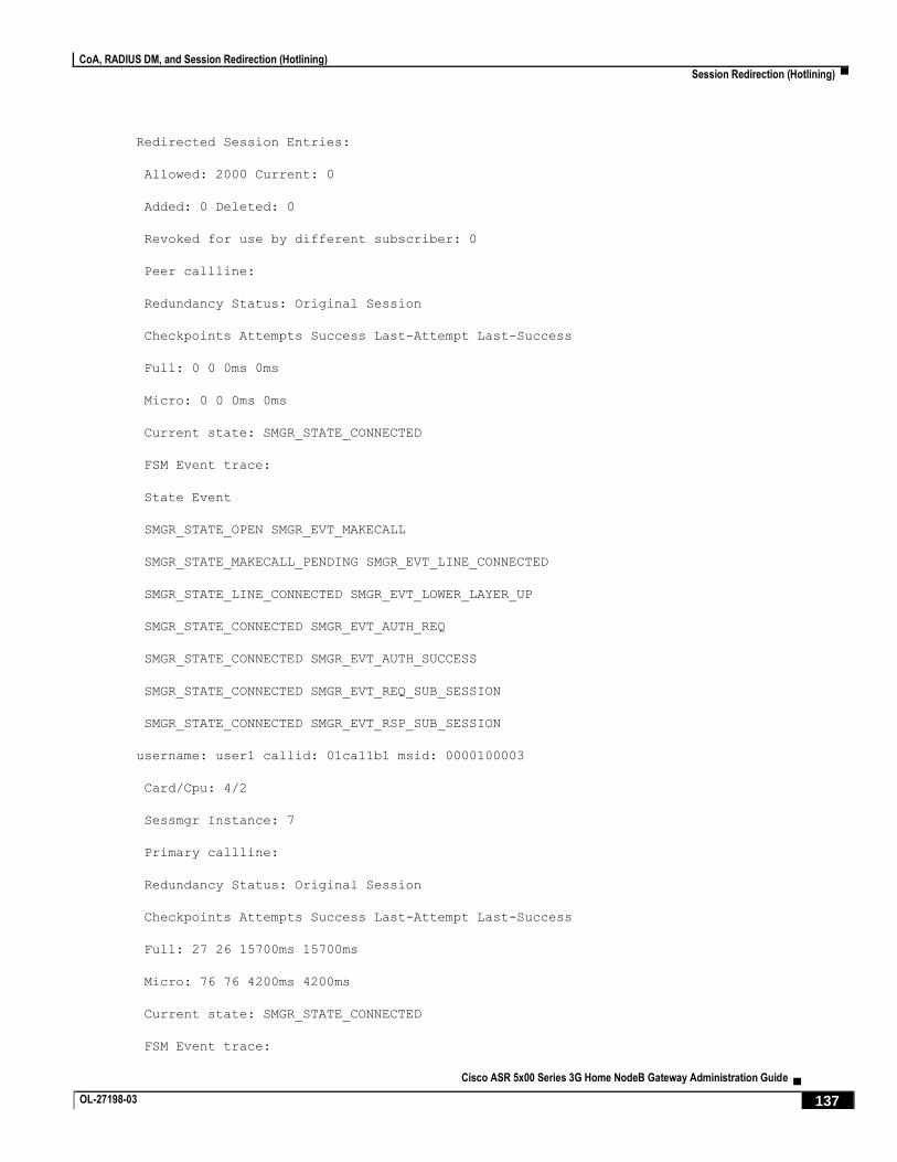
CoA, RADIUS DM, and Session Redirection (Hotlining)
Session Redirection (Hotlining) ▀
Cisco ASR 5x00 Series 3G Home NodeB Gateway Administration Guide ▄ OL-27198-03 137
Redirected Session Entries:
Allowed: 2000 Current: 0
Added: 0 Deleted: 0
Revoked for use by different subscriber: 0
Peer callline:
Redundancy Status: Original Session
Checkpoints Attempts Success Last-Attempt Last-Success
Full: 0 0 0ms 0ms
Micro: 0 0 0ms 0ms
Current state: SMGR_STATE_CONNECTED
FSM Event trace:
State Event
SMGR_STATE_OPEN SMGR_EVT_MAKECALL
SMGR_STATE_MAKECALL_PENDING SMGR_EVT_LINE_CONNECTED
SMGR_STATE_LINE_CONNECTED SMGR_EVT_LOWER_LAYER_UP
SMGR_STATE_CONNECTED SMGR_EVT_AUTH_REQ
SMGR_STATE_CONNECTED SMGR_EVT_AUTH_SUCCESS
SMGR_STATE_CONNECTED SMGR_EVT_REQ_SUB_SESSION
SMGR_STATE_CONNECTED SMGR_EVT_RSP_SUB_SESSION
username: user1 callid: 01ca11b1 msid: 0000100003
Card/Cpu: 4/2
Sessmgr Instance: 7
Primary callline:
Redundancy Status: Original Session
Checkpoints Attempts Success Last-Attempt Last-Success
Full: 27 26 15700ms 15700ms
Micro: 76 76 4200ms 4200ms
Current state: SMGR_STATE_CONNECTED
FSM Event trace:

CoA, RADIUS DM, and Session Redirection (Hotlining)
▀ Session Redirection (Hotlining)
▄ Cisco ASR 5x00 Series 3G Home NodeB Gateway Administration Guide
138 OL-27198-03
State Event
SMGR_STATE_OPEN SMGR_EVT_NEWCALL
SMGR_STATE_NEWCALL_ARRIVED SMGR_EVT_ANSWER_CALL
SMGR_STATE_NEWCALL_ANSWERED SMGR_EVT_LINE_CONNECTED
SMGR_STATE_LINE_CONNECTED SMGR_EVT_LINK_CONTROL_UP
SMGR_STATE_LINE_CONNECTED SMGR_EVT_AUTH_REQ
SMGR_STATE_LINE_CONNECTED SMGR_EVT_IPADDR_ALLOC_SUCCESS
SMGR_STATE_LINE_CONNECTED SMGR_EVT_AUTH_SUCCESS
SMGR_STATE_LINE_CONNECTED SMGR_EVT_UPDATE_SESS_CONFIG
SMGR_STATE_LINE_CONNECTED SMGR_EVT_LOWER_LAYER_UP
Data Reorder statistics
Total timer expiry: 0 Total flush (tmr expiry): 0
Total no buffers: 0 Total flush (no buffers): 0
Total flush (queue full): 0 Total flush (out of range):0
Total flush (svc change): 0 Total out-of-seq pkt drop: 0
Total out-of-seq arrived: 0
IPv4 Reassembly Statistics:
Success: 0 In Progress: 0
Failure (timeout): 0 Failure (no buffers): 0
Failure (other reasons): 0
Redirected Session Entries:
Allowed: 2000 Current: 0
Added: 0 Deleted: 0
Revoked for use by different subscriber: 0
Peer callline:
Redundancy Status: Original Session
Checkpoints Attempts Success Last-Attempt Last-Success
Full: 0 0 0ms 0ms
Micro: 0 0 0ms 0ms
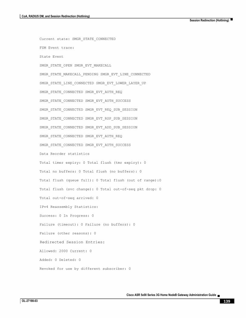
CoA, RADIUS DM, and Session Redirection (Hotlining)
Session Redirection (Hotlining) ▀
Cisco ASR 5x00 Series 3G Home NodeB Gateway Administration Guide ▄ OL-27198-03 139
Current state: SMGR_STATE_CONNECTED
FSM Event trace:
State Event
SMGR_STATE_OPEN SMGR_EVT_MAKECALL
SMGR_STATE_MAKECALL_PENDING SMGR_EVT_LINE_CONNECTED
SMGR_STATE_LINE_CONNECTED SMGR_EVT_LOWER_LAYER_UP
SMGR_STATE_CONNECTED SMGR_EVT_AUTH_REQ
SMGR_STATE_CONNECTED SMGR_EVT_AUTH_SUCCESS
SMGR_STATE_CONNECTED SMGR_EVT_REQ_SUB_SESSION
SMGR_STATE_CONNECTED SMGR_EVT_RSP_SUB_SESSION
SMGR_STATE_CONNECTED SMGR_EVT_ADD_SUB_SESSION
SMGR_STATE_CONNECTED SMGR_EVT_AUTH_REQ
SMGR_STATE_CONNECTED SMGR_EVT_AUTH_SUCCESS
Data Reorder statistics
Total timer expiry: 0 Total flush (tmr expiry): 0
Total no buffers: 0 Total flush (no buffers): 0
Total flush (queue full): 0 Total flush (out of range):0
Total flush (svc change): 0 Total out-of-seq pkt drop: 0
Total out-of-seq arrived: 0
IPv4 Reassembly Statistics:
Success: 0 In Progress: 0
Failure (timeout): 0 Failure (no buffers): 0
Failure (other reasons): 0
Redirected Session Entries:
Allowed: 2000 Current: 0
Added: 0 Deleted: 0
Revoked for use by different subscriber: 0


Cisco ASR 5x00 Series 3G Home NodeB Gateway Administration Guide ▄ OL-27198-03 141
Chapter 8 IP Security
This chapter provides information on configuring an enhanced or extended service. The product Administration Guides
provide examples and procedures for configuration of basic services on the system. It is recommended that you select
the configuration example that best meets your service model, and configure the required elements for that model, as
described in the respective product Administration Guide, before using the procedures in this chapter.
Important: The IP Security is a licensed Cisco feature. A separate feature license may be required. Contact your
Cisco account representative for detailed information on specific licensing requirements. For information on installing
and verifying licenses, refer to the Managing License Keys section of the Software Management Operations chapter in
the System Administration Guide.
Caution: IPSec parameter configurations saved using this release may not function properly with older software
releases.
This chapter contains the following sections:
Overview
IPSec Terminology
Implementing IPSec for PDN Access Applications
Implementing IPSec for Mobile IP Applications
Implementing IPSec for L2TP Applications
Transform Set Configuration
ISAKMP Policy Configuration
ISAKMP Crypto Map Configuration
Dynamic Crypto Map Configuration
Manual Crypto Map Configuration
Crypto Map and Interface Association
FA Services Configuration to Support IPSec
HA Service Configuration to Support IPSec
RADIUS Attributes for IPSec-based Mobile IP Applications
LAC Service Configuration to Support IPSec
Subscriber Attributes for L2TP Application IPSec Support
PDSN Service Configuration for L2TP Support
Redundant IPSec Tunnel Fail-Over

IP Security
▀ Session Redirection (Hotlining)
▄ Cisco ASR 5x00 Series 3G Home NodeB Gateway Administration Guide
142 OL-27198-03
Redundant IPSec Tunnel Fail-over Configuration
Dead Peer Detection (DPD) Configuration
APN Template Configuration to Support L2TP
IPSec for LTE/SAE Networks

IP Security
Overview ▀
Cisco ASR 5x00 Series 3G Home NodeB Gateway Administration Guide ▄ OL-27198-03 143
Overview IP Security (IPSec) is a suite of protocols that interact with one another to provide secure private communications across
IP networks. These protocols allow the system to establish and maintain secure tunnels with peer security gateways.
IPSec can be implemented on the system for the following applications:
PDN Access: Subscriber IP traffic is routed over an IPSec tunnel from the system to a secure gateway on the
packet data network (PDN) as determined by access control list (ACL) criteria. This application can be
implemented for both core network service and HA-based systems. The following figure shows IPSec
configurations.
Figure 11. IPSec Applications
Mobile IP: Mobile IP control signals and subscriber data is encapsulated in IPSec tunnels that are established
between foreign agents (FAs) and home agents (HAs) over the Pi interfaces.
Important: Once an IPSec tunnel is established between an FA and HA for a particular
subscriber, all new Mobile IP sessions using the same FA and HA are passed over the tunnel
regardless of whether or not IPSec is supported for the new subscriber sessions. Data for existing
Mobile IP sessions is unaffected.
L2TP: L2TP-encapsulated packets are routed from the system to an LNS/secure gateway over an IPSec tunnel.

IP Security
▀ Overview
▄ Cisco ASR 5x00 Series 3G Home NodeB Gateway Administration Guide
144 OL-27198-03
Note that: IPSec can be implemented for both attribute-based and compulsory tunneling applications for 3GPP2
services.
Applicable Products and Relevant Sections
The IPSec feature is supported for various products. The following table indicates the products on which the feature is
supported and the relevant sections within the chapter that pertain to that product.
Applicable Product(s) Refer to Sections
PDSN/FA/HA Implementing IPSec for PDN Access Applications
Implementing IPSec for Mobile IP Applications
Transform Set Configuration
ISAKMP Policy Configuration
ISAKMP Crypto Map Configuration
Dynamic Crypto Map Configuration
Manual Crypto Map Configuration
Crypto Map and Interface Association
FA Services Configuration to Support IPSec
HA Service Configuration to Support IPSec
RADIUS Attributes for IPSec-based Mobile IP Applications
LAC Service Configuration to Support IPSec
Subscriber Attributes for L2TP Application IPSec Support
PDSN Service Configuration for L2TP Support
Redundant IPSec Tunnel Fail-Over
Dead Peer Detection (DPD) Configuration

IP Security
Overview ▀
Cisco ASR 5x00 Series 3G Home NodeB Gateway Administration Guide ▄ OL-27198-03 145
Applicable Product(s) Refer to Sections
GGSN/FA/HA Implementing IPSec for PDN Access Applications
Implementing IPSec for Mobile IP Applications
Implementing IPSec for L2TP Applications
Transform Set Configuration
ISAKMP Policy Configuration
ISAKMP Crypto Map Configuration
Dynamic Crypto Map Configuration
Manual Crypto Map Configuration
Crypto Map and Interface Association
FA Services Configuration to Support IPSec
HA Service Configuration to Support IPSec
RADIUS Attributes for IPSec-based Mobile IP Applications
LAC Service Configuration to Support IPSec
Redundant IPSec Tunnel Fail-Over
Dead Peer Detection (DPD) Configuration
TAPN Template Configuration to Support L2TP

IP Security
▀ Overview
▄ Cisco ASR 5x00 Series 3G Home NodeB Gateway Administration Guide
146 OL-27198-03
Applicable Product(s) Refer to Sections
ASN GW Implementing IPSec for PDN Access Applications
Implementing IPSec for Mobile IP Applications
Implementing IPSec for L2TP Applications
Transform Set Configuration
ISAKMP Policy Configuration
ISAKMP Crypto Map Configuration
Dynamic Crypto Map Configuration
Manual Crypto Map Configuration
Crypto Map and Interface Association
FA Services Configuration to Support IPSec
HA Service Configuration to Support IPSec
RADIUS Attributes for IPSec-based Mobile IP Applications
LAC Service Configuration to Support IPSec
Subscriber Attributes for L2TP Application IPSec Support
Redundant IPSec Tunnel Fail-Over
Dead Peer Detection (DPD) Configuration
IP Security
IPSec Terminology ▀
Cisco ASR 5x00 Series 3G Home NodeB Gateway Administration Guide ▄ OL-27198-03 147
IPSec Terminology There are four items related to IPSec support on the system that must be understood prior to beginning configuration.
They are:
Crypto Access Control List (ACL)
Transform Set
ISAKMP Policy
Crypto Map
Crypto Access Control List (ACL)
As described in the IP Access Control Lists chapter of this guide, ACLs on the system define rules, usually permissions,
for handling subscriber data packets that meet certain criteria. Crypto ACLs, however, define the criteria that must be
met in order for a subscriber data packet to be routed over an IPSec tunnel.
Unlike other ACLs that are applied to interfaces, contexts, or one or more subscribers, crypto ACLs are matched with
crypto maps. In addition, crypto ACLs contain only a single rule while other ACL types can consist of multiple rules.
Prior to routing, the system examines the properties of each subscriber data packet. If the packet properties match the
criteria specified in the crypto ACL, the system will initiate the IPSec policy dictated by the crypto map.
Transform Set
Transform Sets are used to define IPSec security associations (SAs). IPSec SAs specify the IPSec protocols to use to
protect packets.
Transform sets are used during Phase 2 of IPSec establishment. In this phase, the system and a peer security gateway
negotiate one or more transform sets (IPSec SAs) containing the rules for protecting packets. This negotiation ensures
that both peers can properly protect and process the packets.
ISAKMP Policy
Internet Security Association Key Management Protocol (ISAKMP) policies are used to define Internet Key Exchange
(IKE) SAs. The IKE SAs dictate the shared security parameters (i.e. which encryption parameters to use, how to
authenticate the remote peer, etc.) between the system and a peer security gateway.
During Phase 1 of IPSec establishment, the system and a peer security gateway negotiate IKE SAs. These SAs are used
to protect subsequent communications between the peers including the IPSec SA negotiation process.
Crypto Map
Crypto Maps define the tunnel policies that determine how IPSec is implemented for subscriber data packets.
There are three types of crypto maps supported by the system. They are:
Manual crypto maps

IP Security
▀ IPSec Terminology
▄ Cisco ASR 5x00 Series 3G Home NodeB Gateway Administration Guide
148 OL-27198-03
ISAKMP crypto maps
Dynamic crypto maps
Manual Crypto Maps
These are static tunnels that use pre-configured information (including security keys) for establishment. Because they
rely on statically configured information, once created, the tunnels never expire; they exist until their configuration is
deleted.
Manual crypto maps define the peer security gateway to establish a tunnel with, the security keys to use to establish the
tunnel, and the IPSec SA to be used to protect data sent/received over the tunnel. Additionally, manual crypto maps are
applied to specific system interfaces.
Important: Because manual crypto map configurations require the use of static security keys (associations), they
are not as secure as crypto maps that rely on dynamically configured keys. Therefore, it is recommended that they only
be configured and used for testing purposes.
ISAKMP Crypto Maps
These tunnels are similar to manual crypto maps in that they require some statically configured information such as the
IP address of a peer security gateway and that they are applied to specific system interfaces.
However, ISAKMP crypto maps offer greater security because they rely on dynamically generated security associations
through the use of the Internet Key Exchange (IKE) protocol.
When ISAKMP crypto maps are used, the system uses the pre-shared key configured for map as part of the Diffie-
Hellman (D-H) exchange with the peer security gateway to initiate Phase 1 of the establishment process. Once the
exchange is complete, the system and the security gateway dynamically negotiate IKE SAs to complete Phase 1. In
Phase 2, the two peers dynamically negotiate the IPSec SAs used to determine how data traversing the tunnel will be
protected.
Dynamic Crypto Maps
These tunnels are used for protecting L2TP-encapsulated data between the system and an LNS/security gateway or
Mobile IP data between an FA service configured on one system and an HA service configured on another.
The system determines when to implement IPSec for L2TP-encapsulated data either through attributes returned upon
successful authentication for attribute based tunneling, or through the configuration of the LAC service used for
compulsory tunneling.
The system determines when to implement IPSec for Mobile IP based on RADIUS attribute values as well as the
configurations of the FA and HA service(s).

IP Security
Implementing IPSec for PDN Access Applications ▀
Cisco ASR 5x00 Series 3G Home NodeB Gateway Administration Guide ▄ OL-27198-03 149
Implementing IPSec for PDN Access Applications This section provides information on the following topics:
How the IPSec-based PDN Access Configuration Works
Configuring IPSec Support for PDN Access
In covering these topics, this section assumes that ISAKMP crypto maps are configured/used as opposed to manual
crypto maps.
How the IPSec-based PDN Access Configuration Works
The following figure and the text that follows describe how sessions accessing a PDN using IPSec are processed by the
system.
Figure 12. IPSec PDN Access Processing
Table 9. IPSec PDN Access Processing
Step Description
1. A subscriber session or PDP context Request, in GGSN service, arrives at the system.
2. The system processes the subscriber session or request as it would typically.
3. Prior to routing the session packets, the system compares them against configured Access Control Lists (ACLs).

IP Security
▀ Implementing IPSec for PDN Access Applications
▄ Cisco ASR 5x00 Series 3G Home NodeB Gateway Administration Guide
150 OL-27198-03
Step Description
4. The system determines that the packet matches the criteria of an ACL that is associated with a configured crypto map.
5. From the crypto map, the system determines the following:
The map type, in this case ISAKMP
The pre-shared key used to initiate the Internet Key Exchange (IKE) and the IKE negotiation mode
The IP address of the security gateway
Whether perfect forward secrecy (PFS) should be enabled for the IPSec SA and if so, what group should be used
IPSec SA lifetime parameters
The name of a configured transform set defining the IPSec SA
6. To initiate the IKE SA negotiation, the system performs a Diffie-Hellman exchange of the pre-shared key specified in the
crypto map with the specified peer security gateway.
7. The system and the security gateway negotiate an ISAKMP policy (IKE SA) to use to protect further communications.
8. Once the IKE SA has been negotiated, the system negotiates an IPSec SA with the security gateway using the transform
method specified in the transform sets.
9. Once the IPSec SA has been negotiated, the system protects the data according to the IPSec SAs established during step 8
and sends it over the IPSec tunnel.
Configuring IPSec Support for PDN Access
This section provides a list of the steps required to configure IPSec functionality on the system in support of PDN
access. Each step listed refers to a different section containing the specific instructions for completing the required
procedure.
Important: These instructions assume that the system was previously configured to support subscriber data
sessions either as a core service or an HA. In addition, parameters configured using this procedure must be configured in
the same destination context on the system.
Step 1 Configure one or more IP access control lists (ACLs) according to the information and instructions located in IP Access
Control Lists chapter of this guide.
Step 2 Configure one or more transform sets according to the instructions located in the Transform Set Configuration section
of this chapter.
Step 3 Configure one or more ISAKMP policies according to the instructions located in the ISAKMP Policy Configuration
section of this chapter.
Step 4 Configure an ipsec-isakmp crypto map according to the instructions located in the ISAKMP Crypto Map Configuration
section of this chapter.
Step 5 Apply the crypto map to an interface on the system according to the instructions located in the Crypto Map and
Interface Association section of this chapter.

IP Security
Implementing IPSec for PDN Access Applications ▀
Cisco ASR 5x00 Series 3G Home NodeB Gateway Administration Guide ▄ OL-27198-03 151
Step 6 Save your configuration to flash memory, an external memory device, and/or a network location using the Exec mode
command save configuration. For additional information on how to verify and save configuration files, refer to the
System Administration Guide and the Command Line Interface Reference.

IP Security
▀ Implementing IPSec for Mobile IP Applications
▄ Cisco ASR 5x00 Series 3G Home NodeB Gateway Administration Guide
152 OL-27198-03
Implementing IPSec for Mobile IP Applications This section provides information on the following topics:
How the IPSec-based Mobile IP Configuration Works
Configuring IPSec Support for Mobile IP
How the IPSec-based Mobile IP Configuration Works
The following figure and the text that follows describe how Mobile IP sessions using IPSec are processed by the system.
Figure 13. IPSec-based Mobile IP Session Processing

IP Security
Implementing IPSec for Mobile IP Applications ▀
Cisco ASR 5x00 Series 3G Home NodeB Gateway Administration Guide ▄ OL-27198-03 153
Table 10. IPSec-based Mobile IP Session Processing
Step Description
1. FA service receives a Mobile IP registration request from the mobile node.
2. FA sends an Access-Request to the FAAA server with the 3GPP2-IKE-Secret-Request attribute equal to yes.
3. The FAAA proxies the request to the HAAA.
4. The HAAA returns an Access-Accept message including the following attributes:
3GPP2-Security-Level set to 3 for IPSec tunnels and registration messages
3GPP2-MIP-HA-Address indicating the IP address of the HA that the FA is to communicate with.
3GPP2-KeyId providing an identification number for the IKE secret (alternatively, the keys may be statically
configured for the FA and/or HA)
3GPP2-IKE-Secret indicating the pre-shared secret to use to negotiate the IKE SA
5. The FAAA passes the accept message to the FA with all of the attributes.
6. The FA determines if an IPSec SA already exists based on the HA address supplied. If so, that SA will be used. If not, a
new IPSec SA will be negotiated.
7. The FA determines the appropriate crypto map to use for IPSec protection based on the HA address attribute. It does this by
comparing the address received to those configured using the isakmp peer-ha command. From the crypto map, the
system determines the following:
The map type, in this case dynamic
Whether perfect forward secrecy (PFS) should be enabled for the IPSec SA and if so, what group should be used
IPSec SA lifetime parameters
The name of one or more configured transform set defining the IPSec SA
8. To initiate the IKE SA negotiation, the FA performs a Diffie-Hellman (D-H) exchange of the ISAKMP secret specified in
the IKE secret attribute with the peer HA dictated by the HA address attribute. Included in the exchange is the Key ID
received from the HAAA.
9. Upon receiving the exchange, the HA sends an access request to the HAAA with the following attributes:
3GPP2-S-Request (note that this attribute is not used if the IPSec keys are statically configured)
3GPP2-User-name (the username specified is the IP addresses of the FA and HA).
The password used in the access request is the RADIUS shared secret.
10. The HAAA returns an Access-Accept message to the HA with the following attributes:
3GPP2-S indicating the “S” secret used to generate the HA’s response to the D-H exchange
3GPP2-S-Lifetime indicating the length of time that the “S” secret is valid
3GPP2-Security-Level set to 3 for IPSec tunnels and registration messages (optional)

IP Security
▀ Implementing IPSec for Mobile IP Applications
▄ Cisco ASR 5x00 Series 3G Home NodeB Gateway Administration Guide
154 OL-27198-03
Step Description
11. The HA determines the appropriate crypto map to use for IPSec protection based on the FA’s address. It does this by
comparing the address received to those configured using the isakmp peer-fa command. From the crypto map, the
system determines the following:
The map type, in this case dynamic
Whether perfect forward secrecy (PFS) should be enabled for the IPSec SA and if so, what group should be used
IPSec SA lifetime parameters
The name of one or more configured transform set defining the IPSec SA
12. The HA creates a response to the D-H exchange using the “S” secret and the Key ID sent by the FA.
13. The HA sends IKE SA negotiation D-H exchange response to the FA.
14. The FA and the HA negotiate an ISAKMP (IKE) policy to use to protect further communications.
15. Once the IKE SA has been negotiated, the system negotiates an IPSec SA with the security gateway using the transform
method specified in the transform sets.
16. Once the IPSec SA has been negotiated, the system protects the data according to the IPSec SAs established during step 15
and sends it over the IPSec tunnel.
Important: Once an IPSec tunnel is established between an FA and HA for a particular subscriber, all new
Mobile IP sessions using the same FA and HA are passed over the tunnel regardless of whether or not IPSec is
supported for the new subscriber sessions. Data for existing Mobile IP sessions is unaffected.
Configuring IPSec Support for Mobile IP
This section provides a list of the steps required to configure IPSec functionality on the system in support of Mobile IP.
Each step listed refers to a different section containing the specific instructions for completing the required procedure.
Important: These instructions assume that the systems were previously configured to support subscriber data
sessions either as an FA or an HA.
Step 1 Configure one or more transform sets for the FA system according to the instructions located in the Transform Set
Configuration section of this chapter.
The transform set(s) must be configured in the same context as the FA service.
Step 2 Configure one or more ISAKMP policies or the FA system according to the instructions located in the ISAKMP Policy
Configuration section of this chapter.
The ISAKMP policy(ies) must be configured in the same context as the FA service.
Step 3 Configure an ipsec-isakmp crypto map or the FA system according to the instructions located in the Dynamic Crypto
Map Configuration section of this chapter.
The crypto map(s) must be configured in the same context as the FA service.
IP Security
Implementing IPSec for Mobile IP Applications ▀
Cisco ASR 5x00 Series 3G Home NodeB Gateway Administration Guide ▄ OL-27198-03 155
Step 4 Optional. Configure DPD for the FA to help prevent IPSec tunnel state mismatches between the FA and HA according
to the instructions located in the Dead Peer Detection (DPD) Configuration section of this chapter.
Important: Though the use of DPD is optional, it is recommended in order to ensure service
availability.
Step 5 Configure the FA Service or the FA system according to the instructions located in the FA Services Configuration to
Support IPSec section of this chapter.
Step 6 Configure one or more transform sets for the HA system according to the instructions located in the Transform Set
Configuration section of this chapter.
The transform set(s) must be configured in the same context as the HA service.
Step 7 Configure one or more ISAKMP policies or the HA system according to the instructions located in the ISAKMP Policy
Configuration section of this chapter.
The ISAKMP policy(ies) must be configured in the same context as the HA service.
Step 8 Configure an ipsec-isakmp crypto map or the HA system according to the instructions located in the Dynamic Crypto
Map Configuration section of this chapter.
The crypto map(s) must be configured in the same context as the HA service.
Step 9 Optional. Configure DPD for the HA to help prevent IPSec tunnel state mismatches between the FA and HA according
to the instructions located in the Dead Peer Detection (DPD) Configuration section of this chapter.
Important: Though the use of DPD is optional, it is recommended in order to ensure service
availability.
Step 10 Configure the HA Service or the HA system according to the instructions located in the section of this chapter.
Step 11 Configure the required attributes for RADIUS-based subscribers according to the information located in the RADIUS
Attributes for IPSec-based Mobile IP Applications section of this chapter.
Step 12 Save your configuration to flash memory, an external memory device, and/or a network location using the Exec mode
command save configuration. For additional information on how to verify and save configuration files, refer to the
System Administration Guide and the Command Line Interface Reference.

IP Security
▀ Implementing IPSec for L2TP Applications
▄ Cisco ASR 5x00 Series 3G Home NodeB Gateway Administration Guide
156 OL-27198-03
Implementing IPSec for L2TP Applications This section provides information on the following topics:
How IPSec is Used for Attribute-based L2TP Configurations
Configuring Support for L2TP Attribute-based Tunneling with IPSec
How IPSec is Used for PDSN Compulsory L2TP Configurations
Configuring Support for L2TP PDSN Compulsory Tunneling with IPSec
How IPSec is Used for L2TP Configurations on the GGSN
Configuring GGSN Support for L2TP Tunneling with IPSec
How IPSec is Used for Attribute-based L2TP Configurations
The following figure and the text that follows describe how IPSec-encrypted attribute-based L2TP sessions are
processed by the system.

IP Security
Implementing IPSec for L2TP Applications ▀
Cisco ASR 5x00 Series 3G Home NodeB Gateway Administration Guide ▄ OL-27198-03 157
Figure 14. Attribute-based L2TP, IPSec-Encrypted Session Processing
Table 11. Attribute-based L2TP, IPSec-Encrypted Session Processing
Step Description
1. A subscriber session arrives at the system.
2. The system attempts to authenticate the subscriber with the AAA server.
3. The profile attributes returned upon successful authentication by the AAA server indicate that session data is to be tunneled
using L2TP. In addition, attributes specifying a crypto map name and ISAKMP secret are also supplied indicating that IP
security is also required.
4. The system determines that the crypto map name supplied matches a configured crypto map.

IP Security
▀ Implementing IPSec for L2TP Applications
▄ Cisco ASR 5x00 Series 3G Home NodeB Gateway Administration Guide
158 OL-27198-03
Step Description
5. From the crypto map, the system determines the following:
The map type, in this case dynamic
Whether perfect forward secrecy (PFS) should be enabled for the IPSec SA and if so, what group should be used
IPSec SA lifetime parameters
The name of one or more configured transform set defining the IPSec SA
6. To initiate the IKE SA negotiation, the system performs a Diffie-Hellman exchange of the ISAKMP secret specified in the
profile attribute with the specified peer LNS/security gateway.
7. The system and the LNS/security gateway negotiate an ISAKMP (IKE) policy to use to protect further communications.
8. Once the IKE SA has been negotiated, the system negotiates an IPSec SA with the LNS/security gateway using the
transform method specified in the transform sets.
9. Once the IPSec SA has been negotiated, the system protects the L2TP encapsulated data according to the IPSec SAs
established during step 9 and sends it over the IPSec tunnel.
Configuring Support for L2TP Attribute-based Tunneling with IPSec
This section provides a list of the steps required to configure IPSec functionality on the system in support of attribute-
based L2TP tunneling. Each step listed refers to a different section containing the specific instructions for completing
the required procedure.
Important: These instructions assume that the system was previously configured to support subscriber data
sessions and L2TP tunneling either as a PDSN or an HA. In addition, with the exception of subscriber attributes, all
other parameters configured using this procedure must be configured in the same destination context on the system as
the LAC service.
Step 1 Configure one or more transform sets according to the instructions located in the Transform Set Configuration section
of this chapter.
Step 2 Configure one or more ISAKMP policies according to the instructions located in the ISAKMP Policy Configuration
section of this chapter.
Step 3 Configure an ipsec-isakmp crypto map according to the instructions located in the Dynamic Crypto Map Configuration
section of this chapter.
Step 4 Configure the subscriber profile attributes according to the instructions located in the Subscriber Attributes for L2TP
Application IPSec Support section of this chapter.
Step 5 Save your configuration to flash memory, an external memory device, and/or a network location using the Exec mode
command save configuration. For additional information on how to verify and save configuration files, refer to the
System Administration Guide and the Command Line Interface Reference.

IP Security
Implementing IPSec for L2TP Applications ▀
Cisco ASR 5x00 Series 3G Home NodeB Gateway Administration Guide ▄ OL-27198-03 159
How IPSec is Used for PDSN Compulsory L2TP Configurations
The following figure and the text that follows describe how IPSec-encrypted PDSN compulsory L2TP sessions are
processed by the system.
Figure 15. PDSN Compulsory L2TP, IPSec-Encrypted Session Processing
Table 12. PDSN Compulsory L2TP, IPSec-Encrypted Session Processing
Step Description
1. A subscriber session arrives at a PDSN service on the system that is configured to perform compulsory tunneling. The
system uses the LAC service specified in the PDSN service’s configuration.
2. The LAC service dictates the peer LNS to use and also specifies the following parameters indicating that IP security is also
required:
Crypto map name
ISAKMP secret
3. The system determines that the crypto map name supplied matches a configured crypto map.

IP Security
▀ Implementing IPSec for L2TP Applications
▄ Cisco ASR 5x00 Series 3G Home NodeB Gateway Administration Guide
160 OL-27198-03
Step Description
4. From the crypto map, the system determines the following:
The map type, in this case dynamic
Whether perfect forward secrecy (PFS) should be enabled for the IPSec SA and if so, what group should be used
IPSec SA lifetime parameters
The name of one or more configured transform set defining the IPSec SA
5. To initiate the IKE SA negotiation, the system performs a Diffie-Hellman exchange of the ISAKMP secret specified by the
attribute with the specified peer LNS/security gateway.
6. The system and the LNS/security gateway negotiate an ISAKMP policy (IKE SA) to use to protect further
communications.
7. Once the IKE SA has been negotiated, the system negotiates an IPSec SA with the LNS/security gateway.
8. Once the IPSec SA has been negotiated, the system protects the L2TP encapsulated data according to the rules specified in
the transform set and sends it over the IPSec tunnel.
Configuring Support for L2TP PDSN Compulsory Tunneling with IPSec
This section provides a list of the steps required to configure IPSec functionality on the system in support of PDSN
compulsory L2TP tunneling. Each step listed refers to a different section containing the specific instructions for
completing the required procedure.
Important: These instructions assume that the system was previously configured to support PDSN compulsory
tunneling subscriber data sessions. In addition, all parameters configured using this procedure must be configured in the
same destination context on the system as the LAC service.
Step 1 Configure one or more transform sets according to the instructions located in the Transform Set Configuration section
of this chapter.
Step 2 Configure one or more ISAKMP policies according to the instructions located in the ISAKMP Policy Configuration
section of this chapter.
Step 3 Configure an ipsec-isakmp crypto map according to the instructions located in the Dynamic Crypto Map Configuration
section of this chapter.
Step 4 Configure the subscriber profile attributes according to the instructions located in the Subscriber Attributes for L2TP
Application IPSec Support section of this chapter.
Step 5 Save your configuration to flash memory, an external memory device, and/or a network location using the Exec mode
command save configuration. For additional information on how to verify and save configuration files, refer to the
System Administration Guide and the Command Line Interface Reference.

IP Security
Implementing IPSec for L2TP Applications ▀
Cisco ASR 5x00 Series 3G Home NodeB Gateway Administration Guide ▄ OL-27198-03 161
How IPSec is Used for L2TP Configurations on the GGSN
The following figure and the text that follows describe how IPSec-encrypted attribute-based L2TP sessions are
processed by the system.
Figure 16. GGSN PDP Context Processing with IPSec-Encrypted L2TP
Table 13. GGSN PDP Context Processing with IPSec-Encrypted L2TP
Step Description
1. A subscriber session/PDP Context Request arrives at the system.
2. The configuration of the APN accessed by the subscriber indicates that session data is to be tunneled using L2TP. In
addition, attributes specifying a crypto map name and ISAKMP secret are also supplied indicating that IP security is also
required.
3. The system determines that the crypto map name supplied matches a configured crypto map.

IP Security
▀ Implementing IPSec for L2TP Applications
▄ Cisco ASR 5x00 Series 3G Home NodeB Gateway Administration Guide
162 OL-27198-03
Step Description
4. From the crypto map, the system determines the following:
The map type, in this case dynamic
Whether perfect forward secrecy (PFS) should be enabled for the IPSec SA and if so, what group should be used
IPSec SA lifetime parameters
The name of one or more configured transform set defining the IPSec SA
5. To initiate the IKE SA negotiation, the system performs a Diffie-Hellman exchange of the ISAKMP secret specified in the
profile attribute with the specified peer LNS/security gateway.
6. The system and the LNS/security gateway negotiate an ISAKMP (IKE) policy to use to protect further communications.
7. Once the IKE SA has been negotiated, the system negotiates an IPSec SA with the LNS/security gateway using the
transform method specified in the transform sets.
8. Once the IPSec SA has been negotiated, the system protects the L2TP encapsulated data according to the IPSec SAs
established during step 9 and sends it over the IPSec tunnel.
Configuring GGSN Support for L2TP Tunneling with IPSec
This section provides a list of the steps required to configure the GGSN to encrypt L2TP tunnels using IPSEC. Each
step listed refers to a different section containing the specific instructions for completing the required procedure.
Important: These instructions assume that the system was previously configured to support subscriber PDP
contexts and L2TP tunneling either as a GGSN. In addition, all parameters configured using this procedure must be
configured in the same destination context on the system as the LAC service.
Step 1 Configure one or more transform sets according to the instructions located in the Transform Set Configuration section
of this chapter.
Step 2 Configure one or more ISAKMP policies according to the instructions located in the ISAKMP Policy Configuration
section of this chapter.
Step 3 Configure an ipsec-isakmp crypto map according to the instructions located in the Dynamic Crypto Map Configuration
section of this chapter.
Step 4 Configure APN support for encrypting L2TP tunnels using IPSec according to the instructions located in the APN
Template Configuration to Support L2TP section of this chapter.
Step 5 Save your configuration to flash memory, an external memory device, and/or a network location using the Exec mode
command save configuration. For additional information on how to verify and save configuration files, refer to the
System Administration Guide and the Command Line Interface Reference.

IP Security
Transform Set Configuration ▀
Cisco ASR 5x00 Series 3G Home NodeB Gateway Administration Guide ▄ OL-27198-03 163
Transform Set Configuration This section provides instructions for configuring transform sets on the system.
Important: This section provides the minimum instruction set for configuring transform set on your system. For
more information on commands that configure additional parameters and options, refer to the Context Configuration
Mode Commands and Crypto Transform Configuration Mode chapters in the Command Line Interface Reference.
To configure the crypto transform set for IPSec:
Step 1 Configure crypto transform set by applying the example configuration in the Configuring Transform Set section.
Step 2 Verify your Crypto Transform Set configuration by following the steps in the Verifying the Crypto Transform Set
Configuration section.
Step 3 Save your configuration to flash memory, an external memory device, and/or a network location using the Exec mode
command save configuration. For additional information on how to verify and save configuration files, refer to the
System Administration Guide and the Command Line Interface Reference.
Configuring Transform Set
Use the following example to create the crypto transform set on your system:
configure
context <ctxt_name>
crypto ipsec transform-set <transform_name> ah hmac { md5-96 | none |sha1-96 } esp
hmac { { md5-96 | none | sha1-96 } { cipher {des-cbc | 3des-cbc | aes-cbc } | none }
mode { transport | tunnel }
end
Notes:
<ctxt_name> is the system context in which you wish to create and configure the crypto transform set(s).
<transform_name> is the name of the crypto transform set in the current context that you want to configure for
IPSec configuration.
For more information on parameters, refer to the IPSec Transform Configuration Mode Commands chapter in
the Command Line Interface Reference.
Verifying the Crypto Transform Set Configuration
These instructions are used to verify the crypto transform set(s) was/were configured.
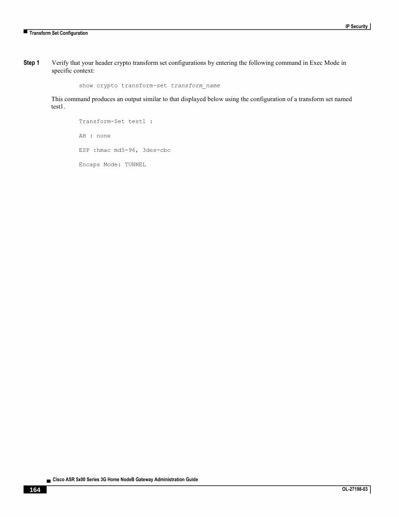
IP Security
▀ Transform Set Configuration
▄ Cisco ASR 5x00 Series 3G Home NodeB Gateway Administration Guide
164 OL-27198-03
Step 1 Verify that your header crypto transform set configurations by entering the following command in Exec Mode in
specific context:
show crypto transform-set transform_name
This command produces an output similar to that displayed below using the configuration of a transform set named
test1.
Transform-Set test1 :
AH : none
ESP :hmac md5-96, 3des-cbc
Encaps Mode: TUNNEL

IP Security
ISAKMP Policy Configuration ▀
Cisco ASR 5x00 Series 3G Home NodeB Gateway Administration Guide ▄ OL-27198-03 165
ISAKMP Policy Configuration This section provides instructions for configuring ISAKMP policies on the system. ISAKMP policy configuration is
only required if the crypto map type is either ISAKMP or Dynamic.
Important: This section provides the minimum instruction set for configuring ISAKMP policies on the system.
For more information on commands that configure additional parameters and options, refer to the Context Configuration
Mode Commands and ISAKMP Configuration Mode Commands chapters in the Command Line Interface Reference.
To configure the ISAKMP policy for IPSec:
Step 1 Configure crypto transform set by applying the example configuration in the Configuring ISAKMP Policy section.
Step 2 Verify your ISAKMP policy configuration by following the steps in the Verifying the ISAKMP Policy Configuration
section.
Step 3 Save your configuration to flash memory, an external memory device, and/or a network location using the Exec mode
command save configuration. For additional information on how to verify and save configuration files, refer to the
System Administration Guide and the Command Line Interface Reference.
Configuring ISAKMP Policy
Use the following example to create the ISAKMP policy on your system:
configure
context <ctxt_name>
ikev1 policy <priority>
encryption { 3des-cbc | des-cbc }
hash { md5 | sha1 }
group { 1 | 2 | 3 | 4 | 5 }
lifetime <time>
end
Notes:
<ctxt_name> is the system context in which you wish to create and configure the ISAKMP policy.
<priority> dictates the order in which the ISAKMP policies are proposed when negotiating IKE SAs.
For more information on parameters, refer to the ISAKMP Configuration Mode Commands chapter in the
Command Line Interface Reference.

IP Security
▀ ISAKMP Policy Configuration
▄ Cisco ASR 5x00 Series 3G Home NodeB Gateway Administration Guide
166 OL-27198-03
Verifying the ISAKMP Policy Configuration
These instructions are used to verify the ISAKMP policy configuration.
Step 1 Verify that your ISAKMP policy configuration by entering the following command in Exec Mode in specific context:
show crypto isakmp policy priority
This command produces an output similar to that displayed below that displays the configuration of an ISAKMP policy
with priority 1.
1 ISAKMP Policies are configured
Priority : 1
Authentication Method : preshared-key
Lifetime : 120 seconds
IKE group : 5
hash : md5
encryption : 3des-cbc
Caution: Modification(s) to an existing ISAKMP policy configuration will not take effect until the
related security association has been cleared. Refer to the clear crypto security-association
command located in the Exec Mode Commands chapter of the Command Line Interface Reference for more
information.
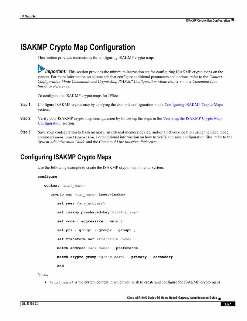
IP Security
ISAKMP Crypto Map Configuration ▀
Cisco ASR 5x00 Series 3G Home NodeB Gateway Administration Guide ▄ OL-27198-03 167
ISAKMP Crypto Map Configuration This section provides instructions for configuring ISAKMP crypto maps.
Important: This section provides the minimum instruction set for configuring ISAKMP crypto maps on the
system. For more information on commands that configure additional parameters and options, refer to the Context
Configuration Mode Commands and Crypto Map ISAKMP Configuration Mode chapters in the Command Line
Interface Reference.
To configure the ISAKMP crypto maps for IPSec:
Step 1 Configure ISAKMP crypto map by applying the example configuration in the Configuring ISAKMP Crypto Maps
section.
Step 2 Verify your ISAKMP crypto map configuration by following the steps in the Verifying the ISAKMP Crypto Map
Configuration section.
Step 3 Save your configuration to flash memory, an external memory device, and/or a network location using the Exec mode
command save configuration. For additional information on how to verify and save configuration files, refer to the
System Administration Guide and the Command Line Interface Reference.
Configuring ISAKMP Crypto Maps
Use the following example to create the ISAKMP crypto map on your system:
configure
context <ctxt_name>
crypto map <map_name> ipsec-isakmp
set peer <agw_address>
set isakmp preshared-key <isakmp_key>
set mode { aggressive | main }
set pfs { group1 | group2 | group5 }
set transform-set <transform_name>
match address <acl_name> [ preference ]
match crypto-group <group_name> { primary | secondary }
end
Notes:
<ctxt_name> is the system context in which you wish to create and configure the ISAKMP crypto maps.
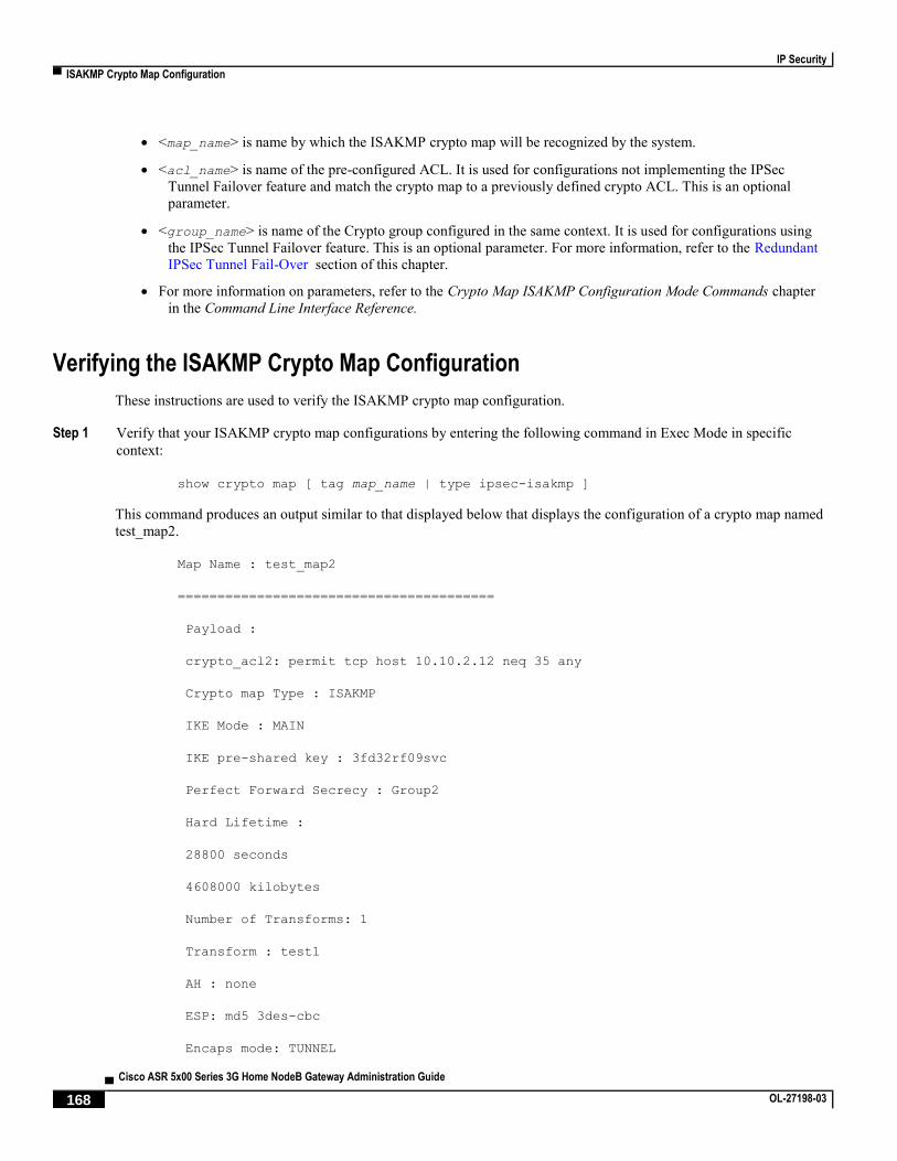
IP Security
▀ ISAKMP Crypto Map Configuration
▄ Cisco ASR 5x00 Series 3G Home NodeB Gateway Administration Guide
168 OL-27198-03
<map_name> is name by which the ISAKMP crypto map will be recognized by the system.
<acl_name> is name of the pre-configured ACL. It is used for configurations not implementing the IPSec
Tunnel Failover feature and match the crypto map to a previously defined crypto ACL. This is an optional
parameter.
<group_name> is name of the Crypto group configured in the same context. It is used for configurations using
the IPSec Tunnel Failover feature. This is an optional parameter. For more information, refer to the Redundant
IPSec Tunnel Fail-Over section of this chapter.
For more information on parameters, refer to the Crypto Map ISAKMP Configuration Mode Commands chapter
in the Command Line Interface Reference.
Verifying the ISAKMP Crypto Map Configuration
These instructions are used to verify the ISAKMP crypto map configuration.
Step 1 Verify that your ISAKMP crypto map configurations by entering the following command in Exec Mode in specific
context:
show crypto map [ tag map_name | type ipsec-isakmp ]
This command produces an output similar to that displayed below that displays the configuration of a crypto map named
test_map2.
Map Name : test_map2
========================================
Payload :
crypto_acl2: permit tcp host 10.10.2.12 neq 35 any
Crypto map Type : ISAKMP
IKE Mode : MAIN
IKE pre-shared key : 3fd32rf09svc
Perfect Forward Secrecy : Group2
Hard Lifetime :
28800 seconds
4608000 kilobytes
Number of Transforms: 1
Transform : test1
AH : none
ESP: md5 3des-cbc
Encaps mode: TUNNEL

IP Security
ISAKMP Crypto Map Configuration ▀
Cisco ASR 5x00 Series 3G Home NodeB Gateway Administration Guide ▄ OL-27198-03 169
Local Gateway: Not Set
Remote Gateway: 192.168.1.1
Caution: Modification(s) to an existing ISAKMP crypto map configuration will not take effect until
the related security association has been cleared. Refer to the clear crypto security-association
command located in the Exec Mode Commands chapter of the Command Line Interface Reference for more
information.
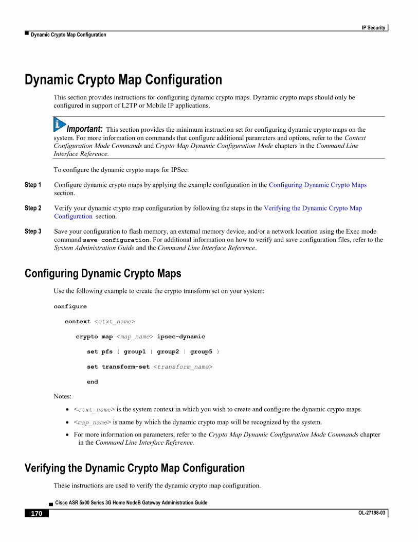
IP Security
▀ Dynamic Crypto Map Configuration
▄ Cisco ASR 5x00 Series 3G Home NodeB Gateway Administration Guide
170 OL-27198-03
Dynamic Crypto Map Configuration This section provides instructions for configuring dynamic crypto maps. Dynamic crypto maps should only be
configured in support of L2TP or Mobile IP applications.
Important: This section provides the minimum instruction set for configuring dynamic crypto maps on the
system. For more information on commands that configure additional parameters and options, refer to the Context
Configuration Mode Commands and Crypto Map Dynamic Configuration Mode chapters in the Command Line
Interface Reference.
To configure the dynamic crypto maps for IPSec:
Step 1 Configure dynamic crypto maps by applying the example configuration in the Configuring Dynamic Crypto Maps
section.
Step 2 Verify your dynamic crypto map configuration by following the steps in the Verifying the Dynamic Crypto Map
Configuration section.
Step 3 Save your configuration to flash memory, an external memory device, and/or a network location using the Exec mode
command save configuration. For additional information on how to verify and save configuration files, refer to the
System Administration Guide and the Command Line Interface Reference.
Configuring Dynamic Crypto Maps
Use the following example to create the crypto transform set on your system:
configure
context <ctxt_name>
crypto map <map_name> ipsec-dynamic
set pfs { group1 | group2 | group5 }
set transform-set <transform_name>
end
Notes:
<ctxt_name> is the system context in which you wish to create and configure the dynamic crypto maps.
<map_name> is name by which the dynamic crypto map will be recognized by the system.
For more information on parameters, refer to the Crypto Map Dynamic Configuration Mode Commands chapter
in the Command Line Interface Reference.
Verifying the Dynamic Crypto Map Configuration
These instructions are used to verify the dynamic crypto map configuration.

IP Security
Dynamic Crypto Map Configuration ▀
Cisco ASR 5x00 Series 3G Home NodeB Gateway Administration Guide ▄ OL-27198-03 171
Step 1 Verify that your dynamic crypto map configurations by entering the following command in Exec Mode in specific
context:
show crypto map [ tag map_name | type ipsec-dynamic ]
This command produces an output similar to that displayed below using the configuration of a dynamic crypto map
named test_map3.
Map Name : test_map3
========================================
Crypto map Type : ISAKMP (Dynamic)
IKE Mode : MAIN
IKE pre-shared key :
Perfect Forward Secrecy : Group2
Hard Lifetime :
28800 seconds
4608000 kilobytes
Number of Transforms: 1
Transform : test1
AH : none
ESP: md5 3des-cbc
Encaps mode: TUNNEL
Local Gateway: Not Set
Remote Gateway: Not Set
Caution: Modification(s) to an existing dynamic crypto map configuration will not take effect until
the related security association has been cleared. Refer to the clear crypto security-association
command located in the Exec Mode Commands chapter of the Command Line Interface Reference for more
information.

IP Security
▀ Manual Crypto Map Configuration
▄ Cisco ASR 5x00 Series 3G Home NodeB Gateway Administration Guide
172 OL-27198-03
Manual Crypto Map Configuration This section provides instructions for configuring manual crypto maps on the system.
Important: Because manual crypto map configurations require the use of static security keys (associations), they
are not as secure as crypto maps that rely on dynamically configured keys. Therefore, it is recommended that they only
be configured and used for testing purposes.
Important: This section provides the minimum instruction set for configuring manual crypto maps on the
system. For more information on commands that configure additional parameters and options, refer to the Context
Configuration Mode Commands and Crypto Map Manual Configuration Mode chapters in the Command Line Interface
Reference.
To configure the manual crypto maps for IPSec:
Step 1 Configure manual crypto map by applying the example configuration in the Configuring Manual Crypto Maps section.
Step 2 Verify your manual crypto map configuration by following the steps in the Verifying the Manual Crypto Map
Configuration section.
Step 3 Save your configuration to flash memory, an external memory device, and/or a network location using the Exec mode
command save configuration. For additional information on how to verify and save configuration files, refer to the
System Administration Guide and the Command Line Interface Reference.
Configuring Manual Crypto Maps
Use the following example to create the manual crypto map on your system:
configure
context <ctxt_name>
crypto map <map_name> ipsec-manual
set peer <agw_address>
match address <acl_name> [ preference ]
set transform-set <transform_name>
set session-key { inbound | outbound } { ah <ah_spi> [ encrypted ] key <ah_key>
| esp <esp_spi> [ encrypted ] cipher <encryption_key> [ encrypted ] authenticator
<auth_key> }
end
Notes:
<ctxt_name> is the system context in which you wish to create and configure the manual crypto maps.

IP Security
Manual Crypto Map Configuration ▀
Cisco ASR 5x00 Series 3G Home NodeB Gateway Administration Guide ▄ OL-27198-03 173
<map_name> is name by which the manual crypto map will be recognized by the system.
<acl_name> is name of the pre-configured ACL. It is used for configurations not implementing the IPSec
Tunnel Failover feature and match the crypto map to a previously defined crypto ACL. This is an optional
parameter.
The length of the configured key must match the configured algorithm.
<group_name> is name of the Crypto group configured in the same context. It is used for configurations using
the IPSec Tunnel Failover feature. This is an optional parameter.
For more information on parameters, refer to the Crypto Map Manual Configuration Mode Commands chapter in
the Command Line Interface Reference.
Verifying the Manual Crypto Map Configuration
These instructions are used to verify the manual crypto map configuration.
Step 1 Verify that your manual crypto map configurations by entering the following command in Exec Mode in specific
context:
show crypto map [ tag map_name | type ipsec-manual ]
This command produces an output similar to that displayed below that displays the configuration of a crypto map named
test_map.
Map Name : test_map
========================================
Payload :
crypto_acl1: permit tcp host 1.2.3.4 gt 30 any
Crypto map Type : manual(static)
Transform : test1
Encaps mode: TUNNEL
Transmit Flow
Protocol : ESP
SPI : 0x102 (258)
Hmac : md5, key: 23d32d23cs89
Cipher : 3des-cbc, key: 1234asd3c3d
Receive Flow
Protocol : ESP
SPI : 0x101 (257) Hmac : md5, key: 008j90u3rjp

IP Security
▀ Manual Crypto Map Configuration
▄ Cisco ASR 5x00 Series 3G Home NodeB Gateway Administration Guide
174 OL-27198-03
Cipher : 3des-cbc, key: sdfsdfasdf342d32
Local Gateway: Not Set
Remote Gateway: 192.168.1.40
Caution: Modification(s) to an existing manual crypto map configuration will not take effect until
the related security association has been cleared. Refer to the clear crypto security-association
command located in the Exec Mode Commands chapter of the Command Line Interface Reference for more
information.

IP Security
Crypto Map and Interface Association ▀
Cisco ASR 5x00 Series 3G Home NodeB Gateway Administration Guide ▄ OL-27198-03 175
Crypto Map and Interface Association This section provides instructions for applying manual or ISAKMP crypto maps to interfaces configured on the system.
Dynamic crypto maps should not be applied to interfaces.
Important: This section provides the minimum instruction set for applying manual or ISAKMP crypto maps to
an interface on the system. For more information on commands that configure additional parameters and options, refer
to the Command Line Interface Reference.
To apply the crypto maps to an interface:
Step 1 Configure a manual or ISAKMP crypto map by applying the example configuration in any of the following sections:
Step 2 Apply desired crypto map to system interface by following the steps in the Applying Crypto Map to an Interface
section
Step 3 Verify your manual crypto map configuration by following the steps in the Verifying the Interface Configuration with
Crypto Map section.
Step 4 Save your configuration to flash memory, an external memory device, and/or a network location using the Exec mode
command save configuration. For additional information on how to verify and save configuration files, refer to the
System Administration Guide and the Command Line Interface Reference.
Applying Crypto Map to an Interface
Use the following example to apply an existing crypto map to an interface on your system:
configure
context <ctxt_name>
interface <interface_name>
crypto-map <map_name>
end
Notes:
<ctxt_name> is the system context in which the interface is configured to apply crypto map.
<interface_name> is the name of a specific interface configured in the context to which the crypto map will
be applied.
<map_name> is name of the preconfigured ISAKMP or a manual crypto map.
Verifying the Interface Configuration with Crypto Map
These instructions are used to verify the interface configuration with crypto map.

IP Security
▀ Crypto Map and Interface Association
▄ Cisco ASR 5x00 Series 3G Home NodeB Gateway Administration Guide
176 OL-27198-03
Step 1 Verify that your interface is configured properly with crypto map by entering the following command in Exec Mode in
specific context:
show configuration context ctxt_name | grep interface
The interface configuration aspect of the display should look similar to that shown below. In this example an interface
named 20/6 was configured with a crypto map called isakmp_map1.
interface 20/6
ip address 192.168.4.10 255.255.255.0
crypto-map isakmp_map1

IP Security
FA Services Configuration to Support IPSec ▀
Cisco ASR 5x00 Series 3G Home NodeB Gateway Administration Guide ▄ OL-27198-03 177
FA Services Configuration to Support IPSec This section provides instructions for configuring FA services to support IPSec.
These instructions assume that the FA service was previously configured and system is ready to serve as an FA.
Important: This section provides the minimum instruction set for configuring an FA service to support IPSec on
the system. For more information on commands that configure additional parameters and options, refer to the Command
Line Interface Reference.
To configure the FA service to support IPSec:
Step 1 Modify FA service configuration by following the steps in the Modifying FA service to Support IPSec section
Step 2 Verify your FA service configuration by following the steps in the Verifying the FA Service Configuration with IPSec
section.
Step 3 Save your configuration to flash memory, an external memory device, and/or a network location using the Exec mode
command save configuration. For additional information on how to verify and save configuration files, refer to the
System Administration Guide and the Command Line Interface Reference.
Modifying FA service to Support IPSec
Use the following example to modify FA service to support IPSec on your system:
configure
context <ctxt_name>
fa-service <fa_svc_name>
isakmp peer-ha <ha_address> crypto-map <map_name> [ secret <preshared_secret> ]
isakmp default crypto-map <map_name> [ secret <preshared_secret> ]
end
Notes:
<ctxt_name> is the system context in which the FA service is configured to support IPSec.
<fa_svc_name> is name of the FA service for which you are configuring IPSec.
<ha_address> is IP address of the HA service to which FA service will communicate on IPSec.
<map_name> is name of the preconfigured ISAKMP or a manual crypto map.
A default crypto map for the FA service to be used in the event that the AAA server returns an HA address that
is not configured as an ISAKMP peer HA.
For maximum security, the default crypto map should be configured in addition to peer-ha crypto maps instead
of being used to provide IPSec SAs to all HAs. Note that once an IPSec tunnel is established between the FA
and HA for a particular subscriber, all new Mobile IP sessions using the same FA and HA are passed over the

IP Security
▀ FA Services Configuration to Support IPSec
▄ Cisco ASR 5x00 Series 3G Home NodeB Gateway Administration Guide
178 OL-27198-03
tunnel regardless of whether or not IPSec is supported for the new subscriber sessions. Data for existing
Mobile IP sessions is unaffected.
Verifying the FA Service Configuration with IPSec
These instructions are used to verify the FA service to support IPSec.
Step 1 Verify that your FA service is configured properly with IPSec by entering the following command in Exec Mode in
specific context:
show fa-service { name service_name | all }
The output of this command is a concise listing of FA service parameter settings configured on the system.

IP Security
HA Service Configuration to Support IPSec ▀
Cisco ASR 5x00 Series 3G Home NodeB Gateway Administration Guide ▄ OL-27198-03 179
HA Service Configuration to Support IPSec This section provides instructions for configuring HA services to support IPSec.
These instructions assume that the HA service was previously configured and system is ready to serve as an HA.
Important: This section provides the minimum instruction set for configuring an HA service to support IPSec on
the system. For more information on commands that configure additional parameters and options, refer to the Command
Line Interface Reference.
To configure the HA service to support IPSec:
Step 1 Modify HA service configuration by following the steps in the Modifying HA service to Support IPSec section
Step 2 Verify your HA service configuration by following the steps in the Verifying the HA Service Configuration with IPSec
section.
Step 3 Save your configuration to flash memory, an external memory device, and/or a network location using the Exec mode
command save configuration. For additional information on how to verify and save configuration files, refer to the
System Administration Guide and the Command Line Interface Reference.
Modifying HA service to Support IPSec
Use the following example to modify an existing HA service to support IPSec on your system:
configure
context <ctxt_name>
ha-service <ha_svc_name>
isakmp aaa-context <aaa_ctxt_name>
isakmp peer-fa <fa_address> crypto-map <map_name> [ secret <preshared_secret> ]
end
Notes:
<ctxt_name> is the system context in which the FA service is configured to support IPSec.
<ha_svc_name> is name of the HA service for which you are configuring IPSec.
<fa_address> is IP address of the FA service to which HA service will communicate on IPSec.
<aaa_ctxt_name> name of the context through which the HA service accesses the HAAA server to fetch the
IKE S Key and S Lifetime parameters.
<map_name> is name of the preconfigured ISAKMP or a manual crypot map.

IP Security
▀ HA Service Configuration to Support IPSec
▄ Cisco ASR 5x00 Series 3G Home NodeB Gateway Administration Guide
180 OL-27198-03
Verifying the HA Service Configuration with IPSec
These instructions are used to verify the HA service to support IPSec.
Step 1 Verify that your HA service is configured properly with IPSec by entering the following command in Exec Mode in
specific context:
show ha-service { name service_name | all }
The output of this command is a concise listing of HA service parameter settings configured on the system.

IP Security
RADIUS Attributes for IPSec-based Mobile IP Applications ▀
Cisco ASR 5x00 Series 3G Home NodeB Gateway Administration Guide ▄ OL-27198-03 181
RADIUS Attributes for IPSec-based Mobile IP Applications As described in the How the IPSec-based Mobile IP Configuration Works section of this chapter, the system uses
attributes stored in a subscriber’s RADIUS profile to determine how IPSec should be implemented.
The table below lists the attributes that must be configured in the subscriber’s RADIUS attributes to support IPSec for
Mobile IP. These attributes are contained in the following dictionaries:
3GPP2
3GPP2-835
Starent
Starent-835
Starent-VSA1
Starent-VSA1-835
Table 14. Attributes Used for Mobile IP IPSec Support
Attribute Description Variable
3GPP2-
Security-
Level
This attribute indicates the type of security
that the home network mandates on the
visited network.
Integer value:
3 : Enables IPSec for tunnels and registration messages
4 : Disables IPSec
3GPP2 -
KeyId
This attribute contains the opaque IKE
Key Identifier for the FA/HA shared IKE
secret.
Supported value for the first eight bytes is the network-order FA IP
address in hexadecimal characters.
Supported value for the next eight bytes is the network-order HA IP
address in hexadecimal characters.
Supported value for the final four bytes is a timestamp in network
order, indicating when the key was created, and is the number of
seconds since January 1, 1970, UTC.
3GPP2-IKE-
Secret
This attribute contains the FA/HA shared
secret for the IKE protocol. This attribute
is salt-encrypted.
A binary string of 1 to 127 bytes.
3GPP2-S This attribute contains the 'S' secret
parameter used to make the IKE pre-
shared secret.
A binary string of the value of 'S' consisting of 1 to 127 characters.
3GPP2- S-
Lifetime
This attribute contains the lifetime of the
'S' secret parameter used to make the IKE
pre-shared secret.
An integer in network order, indicating the time in seconds since
January 1, 1970 00:00
UTC. Note that this is equivalent to the Unix operating system
expression of time.

IP Security
▀ LAC Service Configuration to Support IPSec
▄ Cisco ASR 5x00 Series 3G Home NodeB Gateway Administration Guide
182 OL-27198-03
LAC Service Configuration to Support IPSec This section provides instructions for configuring LAC services to support IPSec.
Important: These instructions are required for compulsory tunneling. They should only be performed for
attribute-based tunneling if the Tunnel-Service-Endpoint, the SN1-Tunnel-ISAKMP-Crypto-Map, or the SN1 -Tunnel-
ISAKMP-Secret are not configured in the subscriber profile.
These instructions assume that the LAC service was previously configured and system is ready to serve as an LAC
server.
Important: This section provides the minimum instruction set for configuring an LAC service to support IPSec
on the system. For more information on commands that configure additional parameters and options, refer to the
Command Line Interface Reference.
To configure the LAC service to support IPSec:
Step 1 Modify LAC service configuration by following the steps in the Modifying LAC service to Support IPSec section.
Step 2 Verify your LAC service configuration by following the steps in the Verifying the LAC Service Configuration with
IPSec section.
Step 3 Save your configuration to flash memory, an external memory device, and/or a network location using the Exec mode
command save configuration. For additional information on how to verify and save configuration files, refer to the
System Administration Guide and the Command Line Interface Reference.
Modifying LAC service to Support IPSec
Use the following example to modify an existing LAC service to support IPSec on your system:
configure
context <ctxt_name>
lac-service <lac_svc_name>
peer-lns <ip_address> [encrypted] secret <secret> [crypto-map <map_name> {
[encrypted] isakmp-secret <secret> } ] [ description <text> ] [ preference <integer>]
isakmp aaa-context <aaa_ctxt_name>
isakmp peer-fa <fa_address> crypto-map <map_name> [ secret <preshared_secret> ]
end
Notes:
<ctxt_name> is the destination context where the LAC service is configured to support IPSec.

IP Security
LAC Service Configuration to Support IPSec ▀
Cisco ASR 5x00 Series 3G Home NodeB Gateway Administration Guide ▄ OL-27198-03 183
<lac_svc_name> is name of the LAC service for which you are configuring IPSec.
<lns_address> is IP address of the LNS node to which LAC service will communicate on IPSec.
<aaa_ctxt_name> name of the context through which the HA service accesses the HAAA server to fetch the
IKE S Key and S Lifetime parameters.
<map_name> is name of the preconfigured ISAKMP or a manual crypot map.
Verifying the LAC Service Configuration with IPSec
These instructions are used to verify the LAC service to support IPSec.
Step 1 Verify that your LAC service is configured properly with IPSec by entering the following command in Exec Mode in
specific context:
show lac-service nameservice_name
The output of this command is a concise listing of LAC service parameter settings configured on the system.

IP Security
▀ Subscriber Attributes for L2TP Application IPSec Support
▄ Cisco ASR 5x00 Series 3G Home NodeB Gateway Administration Guide
184 OL-27198-03
Subscriber Attributes for L2TP Application IPSec Support In addition to the subscriber profile attributes listed in the RADIUS and Subscriber Profile Attributes Used section of the
L2TP Access Concentrator chapter in this guide, the table below lists the attributes required to support IPSec for use
with attribute-based L2TP tunneling.
These attributes are contained in the following dictionaries:
Starent
Starent-835
Table 15. Subscriber Attributes for IPSec encrypted L2TP Support
RADIUS Attribute Local SubscriberAttribute
Description Variable
SN1-Tunnel-
ISAKMP-
Crypto-Map
tunnel l2tp crypto-map The name of a crypto map
configured on the system.
A salt-encrypted ascii string specifying the
crypto-map to use for this subscriber. It can be
tagged, in which case it is treated as part of a
tunnel group.
SN1 -Tunnel-
ISAKMP- Secret
tunnel l2tp crypto-map
isakmp-secret
The pre-shared secret that will
be used as part of the D-H
exchange to negotiate an IKE
SA.
A salt-encrypted string specifying the IKE
secret. It can be tagged, in which case it is
treated as part of a tunnel group.

IP Security
PDSN Service Configuration for L2TP Support ▀
Cisco ASR 5x00 Series 3G Home NodeB Gateway Administration Guide ▄ OL-27198-03 185
PDSN Service Configuration for L2TP Support PDSN service configuration is required for compulsory tunneling and optional for attribute-based tunneling.
For attribute-based tunneling, a configuration error could occur such that upon successful authentication, the system
determines that the subscriber session requires L2TP but can not determine the name of the context in which the
appropriate LAC service is configured from the attributes supplied. As a precautionary, a parameter has been added to
the PDSN service configuration options that will dictate the name of the context to use. It is strongly recommended that
this parameter be configured.
This section contains instructions for modifying the PDSN service configuration for either compulsory or attribute-
based tunneling.
These instructions assume that the PDSN service was previously configured and system is ready to serve as a PDSN.
This section provides the minimum instruction set for configuring an L2TP service on the PDSN system. For more
information on commands that configure additional parameters and options, refer to the Command Line Interface
Reference.
To configure the PDSN service to support L2TP:
Step 1 Modify PDSN service to configure compulsory tunneling or attribute-based tunneling by applying the example
configuration in any of the following sections:
Modifying PDSN service to Support Attribute-based L2TP Tunneling
Modifying PDSN service to Support Compulsory L2TP Tunneling
Step 2 Verify your LAC service configuration by following the steps in the Verifying the PDSN Service Configuration for
L2TP section.
Step 3 Save your configuration to flash memory, an external memory device, and/or a network location using the Exec mode
command save configuration. For additional information on how to verify and save configuration files, refer to the
System Administration Guide and the Command Line Interface Reference.
Modifying PDSN service to Support Attribute-based L2TP Tunneling
Use the following example to modify an existing PDSN service to support attribute-based L2TP tunneling on your
system:
configure
context <ctxt_name>
pdsn-service <pdsn_svc_name>
ppp tunnel-context <lac_ctxt_name>
end
Notes:
<ctxt_name> is the destination context where the PDSN service is configured.

IP Security
▀ PDSN Service Configuration for L2TP Support
▄ Cisco ASR 5x00 Series 3G Home NodeB Gateway Administration Guide
186 OL-27198-03
<pdsn_svc_name> is name of the PDSN service for which you are configuring attribute-based L2TP tunneling.
<lac_ctxt_name> is the name of the destination context where the LAC service is located.
Modifying PDSN service to Support Compulsory L2TP Tunneling
Use the following example to modify an existing PDSN service to support compulsory L2TP tunneling on your system:
configure
context <ctxt_name>
pdsn-service <pdsn_svc_name>
ppp tunnel-context <lac_ctxt_name>
ppp tunnel-type l2tp
end
Notes:
<ctxt_name> is the destination context where the PDSN service is configured.
<pdsn_svc_name> is name of the PDSN service for which you are configuring attribute-based L2TP tunneling.
<lac_ctxt_name> is name of the destination context where the LAC service is located.
Verifying the PDSN Service Configuration for L2TP
These instructions are used to verify the PDSN service to support L2TP.
Step 1 Verify that your PDSN service is configured properly with L2TP by entering the following command in Exec Mode in
specific context:
show pdsn-service name service_name
The output of this command is a concise listing of PDSN service parameter settings configured on the system.

IP Security
Redundant IPSec Tunnel Fail-Over ▀
Cisco ASR 5x00 Series 3G Home NodeB Gateway Administration Guide ▄ OL-27198-03 187
Redundant IPSec Tunnel Fail-Over The Redundant IPSec Tunnel Fail-Over functionality is included with the IPSec feature license and allows the
configuration of a secondary ISAKMP crypto map-based IPSec tunnel over which traffic is routed in the event that the
primary ISAKMP crypto map-based tunnel cannot be used.
This feature introduces the concept of crypto (tunnel) groups when using IPSec tunnels for access to packet data
networks (PDNs). A crypto group consists of two configured ISAKMP crypto maps. Each crypto map defines the IPSec
policy for a tunnel. In the crypto group, one tunnel serves as the primary, the other as the secondary (redundant). Note
that the method in which the system determines to encrypt user data in an IPSec tunnel remains unchanged.
Group tunnels are perpetually maintained with IPSec Dead Peer Detection (DPD) packets exchanged with the peer
security gateway.
Important: The peer security gateway must support RFC 3706 in order for this functionality to function
properly.
When the system determines that incoming user data traffic must be routed over one of the tunnels in a group, the
system automatically uses the primary tunnel until either the peer is unreachable (the IPSec DPD packets cease), or the
IPSec tunnel fails to re-key. If the primary peer becomes unreachable, the system automatically begins to switch user
traffic to the secondary tunnel. The system can be configured to either automatically switch user traffic back to the
primary tunnel once the corresponding peer security gateway is reachable and the tunnel is configured, or require
manual intervention to do so.
This functionality also supports the generation of Simple network Management Protocol (SNMP) notifications
indicating the following conditions:
Primary Tunnel is down: A primary tunnel that was previously "up" is now "down" representing an error
condition.
Primary Tunnel is up: A primary tunnel that was previously "down" is now "up".
Secondary tunnel is down: A secondary tunnel that was previously "up" is now "down" representing an error
condition.
Secondary Tunnel is up: A secondary tunnel that was previously "down" is now "up".
Fail-over successful: The switchover of user traffic was successful. This is generated for both primary-to-
secondary and secondary-to-primary switchovers.
Unsuccessful fail-over: An error occurred when switching user traffic from either the primary to secondary
tunnel or the secondary to primary tunnel.
Supported Standards
Support for the following standards and requests for comments (RFCs) has been added with the Redundant IPSec
Tunnel Fail-over functionality:
RFC 3706, A Traffic-Based Method of Detecting Dead Internet Key Exchange (IKE) Peers, February 2004

IP Security
▀ Redundant IPSec Tunnel Fail-over Configuration
▄ Cisco ASR 5x00 Series 3G Home NodeB Gateway Administration Guide
188 OL-27198-03
Redundant IPSec Tunnel Fail-over Configuration This section provides information and instructions for configuring the Redundant IPSec Tunnel Fail-over feature. These
instructions assume that the system was previously configured to support subscriber data sessions either as a core
service or an HA.
Important: Parameters configured using this procedure must be configured in the same context on the system.
Important: The system supports a maximum of 32 crypto groups per context. However, configuring crypto
groups to use the same loopback interface for secondary IPSec tunnels is not recommended and may compromise
redundancy on the chassis.
Important: This section provides the minimum instruction set for configuring crypto groups on the system. For
more information on commands that configure additional parameters and options, refer Command Line Interface
Reference.
To configure the Crypto group to support IPSec:
Step 1 Configure a crypto group by following the steps in the Configuring Crypto Group section
Step 2 Configure one or more ISAKMP policies according to the instructions provided in the ISAKMP Policy Configuration
section of this chapter.
Step 3 Configure IPSec DPD settings using the instructions provided in the Dead Peer Detection (DPD) Configuration section
of this chapter.
Step 4 Configure an ISAKMP crypto map for the primary and secondary tunnel according to the instructions provided in the
ISAKMP Crypto Map Configuration section of this chapter.
Step 5 Match the existing ISAKMP crypto map to Crypto group by following the steps in the Modify ISAKMP Crypto Map
Configuration to Match Crypto Group section
Step 6 Verify your Crypto Group configuration by following the steps in the Verifying the Crypto Group Configuration
section.
Step 7 Save your configuration to flash memory, an external memory device, and/or a network location using the Exec mode
command save configuration. For additional information on how to verify and save configuration files, refer to the
System Administration Guide and the Command Line Interface Reference.
Configuring Crypto Group
Use the following example to configure a crypto group on your system for redundant IPSec tunnel fail-over support:
configure
context <ctxt_name>
ikev1 keepalive dpd interval <dur> timeout <dur> num-retry <retries>

IP Security
Redundant IPSec Tunnel Fail-over Configuration ▀
Cisco ASR 5x00 Series 3G Home NodeB Gateway Administration Guide ▄ OL-27198-03 189
crypto-group <group_name>
match address <acl_name> [ <preference> ]
switchover auto [ do-not-revert ]
end
Notes:
<ctxt_name> is the destination context where the Crypto Group is to be configured.
<group_name> is name of the Crypto group you want to configure for IPSec tunnel failover support.
<acl_name> is name of the pre-configured crypto ACL. It is used for configurations not implementing the
IPSec Tunnel Failover feature and match the crypto map to a previously defined crypto ACL. For more
information on crypto ACL, refer Crypto Access Control List (ACL) section of this chapter.
Modify ISAKMP Crypto Map Configuration to Match Crypto Group
Use the following example to match the crypto group with ISAKMP crypto map on your system:
configure
context <ctxt_name>
crypto map <map_name1> ipsec-isakmp
match crypto-group <group_name> primary
end
configure
context <ctxt_name>
crypto map <map_name> ipsec-isakmp
match crypto-group <group_name> secondary
end
Notes:
<ctxt_name> is the system context in which you wish to create and configure the ISAKMP crypto maps.
<group_name> is name of the Crypto group configured in the same context for IPSec Tunnel Failover feature.
<map_name1> is name of the preconfigured ISAKMP crypto map to match with crypto group as primary.
<map_name2> is name of the preconfigured ISAKMP crypto map to match with crypto group as secondary.
Verifying the Crypto Group Configuration
These instructions are used to verify the crypto group configuration.

IP Security
▀ Redundant IPSec Tunnel Fail-over Configuration
▄ Cisco ASR 5x00 Series 3G Home NodeB Gateway Administration Guide
190 OL-27198-03
Step 1 Verify that your system is configured properly with crypto group by entering the following command in Exec Mode in
specific context:
show crypto group [ summary | name group_name ]
The output of this command is a concise listing of crypto group parameter settings configured on the system.

IP Security
Dead Peer Detection (DPD) Configuration ▀
Cisco ASR 5x00 Series 3G Home NodeB Gateway Administration Guide ▄ OL-27198-03 191
Dead Peer Detection (DPD) Configuration This section provides instructions for configuring the Dead Peer Detection (DPD).
Defined by RFC 3706, Dead Peer Detection (DPD) is used to simplify the messaging required to verify communication
between peers and tunnel availability.
DPD is configured at the context level and is used in support of the IPSec Tunnel Failover feature (refer to the
Redundant IPSec Tunnel Fail-Over section) and/or to help prevent tunnel state mismatches between an FA and HA
when IPSec is used for Mobile IP applications. When used with Mobile IP applications, DPD ensures the availability of
tunnels between the FA and HA. (Note that the starIPSECDynTunUp and starIPSECDynTunDown SNMP traps are
triggered to indicate tunnel state for the Mobile IP scenario.)
Regardless of the application, DPD must be supported/configured on both security peers. If the system is configured
with DPD but it is communicating with a peer that does not have DPD configured, IPSec tunnels still come up.
However, the only indication that the remote peer does not support DPD exists in the output of the show crypto
isakmp security-associations summary command.
Important: If DPD is enabled while IPSec tunnels are up, it will not take affect until all of the tunnels are
cleared.
Important: DPD must be configured in the same context on the system as other IPSec Parameters.
To configure the Crypto group to support IPSec:
Step 1 Enable dead peer detection on system in support of the IPSec Tunnel Failover feature by following the steps in the
Configuring Crypto Group section
Step 2 Verify your Crypto Group configuration by following the steps in the Verifying the DPD Configuration section.
Step 3 Save your configuration to flash memory, an external memory device, and/or a network location using the Exec mode
command save configuration. For additional information on how to verify and save configuration files, refer to the
System Administration Guide and the Command Line Interface Reference.
Configuring Crypto Group
Use the following example to configure a crypto group on your system for redundant IPSec tunnel fail-over support:
configure
context <ctxt_name>
ikev1 keepalive dpd interval <dur> timeout <dur> num-retry <retries>
end
Notes:
<ctxt_name> is the destination context where the Crypto Group is to be configured.

IP Security
▀ Dead Peer Detection (DPD) Configuration
▄ Cisco ASR 5x00 Series 3G Home NodeB Gateway Administration Guide
192 OL-27198-03
Verifying the DPD Configuration
These instructions are used to verify the dead peer detection configuration.
Step 1 Verify that your system is configured properly with crypto group with DPD by entering the following command in Exec
Mode in specific context:
show crypto group [ summary | name group_name ]
The output of this command is a concise listing of crypto group parameter settings configured on the system.

IP Security
APN Template Configuration to Support L2TP ▀
Cisco ASR 5x00 Series 3G Home NodeB Gateway Administration Guide ▄ OL-27198-03 193
APN Template Configuration to Support L2TP This section provides instructions for adding L2TP support for APN templates configured on the system.
These instructions assume that the APN template was previously configured on this system.
Important: This section provides the minimum instruction set for configuring an APN template to support L2TP
for APN. For more information on commands that configure additional parameters and options, refer to the Command
Line Interface Reference. To configure the APN to support L2TP:
Step 1 Modify preconfigured APN template by following the steps in the Modifying APN Template to Support L2TP section
Step 2 Verify your APN configuration by following the steps in the Verifying the APN Configuration for L2TP section.
Step 3 Save your configuration to flash memory, an external memory device, and/or a network location using the Exec mode
command save configuration. For additional information on how to verify and save configuration files, refer to the
System Administration Guide and the Command Line Interface Reference.
Modifying APN Template to Support L2TP
Use the following example to modify APN template to support L2TP:
configure
context <ctxt_name>
apn <apn_name>
tunnel l2tp [ peer-address <lns_address> [ [ encrypted ] secret <l2tp_secret> ]
[ preference <num> ] [ tunnel-context <tunnel_ctxt_name> ] [ local-address
<agw_ip_address> ] [ crypto-map <map_name> { [ encrypted ] isakmp-secret <crypto_secret>
} ]
end
Notes:
<ctxt_name> is the system context in which the APN template is configured.
<apn_name> is name of the preconfigured APN template in which you want to configure L2TP support.
<lns_address> is IP address of the LNS node to which this APN will communicate.
<tunnel_ctxt_name> is the L2TP context in which the L2TP tunnel is configured.
<agw_ip_address> is the local IP address of the GGSN in which this APN template is configured.
<map_name> is the preconfigured crypto map (ISAKMP or manual) which is to use for L2TP.

IP Security
▀ APN Template Configuration to Support L2TP
▄ Cisco ASR 5x00 Series 3G Home NodeB Gateway Administration Guide
194 OL-27198-03
Verifying the APN Configuration for L2TP
These instructions are used to verify the APN template configuration for L2TP.

IP Security
IPSec for LTE/SAE Networks ▀
Cisco ASR 5x00 Series 3G Home NodeB Gateway Administration Guide ▄ OL-27198-03 195
IPSec for LTE/SAE Networks The Cisco MME (Mobility Management Entity), S-GW (Serving Gateway), and P-GW (Packet Data Network Gateway)
support IPSec and IKEv2 encryption using IPv4 and IPv6 addressing in LTE/SAE (Long Term Evolution/System
Architecture Evolution) networks. IPSec and IKEv2 encryption enables network domain security for all IP packet-
switched networks, providing confidentiality, integrity, authentication, and anti-replay protection via secure IPSec
tunnels.
Encryption Algorithms
IPSec for LTE/SAE supports the following control and data path encryption algorithms:
AES-CBC-128 (Advanced Encryption Standard-Cipher Block Chaining-128)
AES-CBC-256 (Advanced Encryption Standard-Cipher Block Chaining-256)
DES-CBC (Data Encryption Standard-Cipher Block Chaining)
3DES-CBC (Triple Data Encryption Standard-Cipher Bock Chaining)
HMAC Functions
IPSec for LTE/SAE supports the following data path HMAC (Hash-based Message Authentication Code) functions:
AES-XCBC-MAC-96 (Advanced Encryption Standard-X Cipher Block Chaining-Message Authentication Code-
96)
MD5-96 (Message Digest 5-96)
SHA1-96 (Secure Hash Algorithm 1-96)
IPSec for LTE/SAE supports the following control path HMAC (Hash-based Message Authentication Code) functions:
AES-XCBC-MAC-96 (Advanced Encryption Standard-X Cipher Block Chaining-Message Authentication Code-
96)
MD5-96 (Message Digest 5-96)
SHA1-96 (Secure Hash Algorithm 1-96)
SHA2-256-128 (Secure Hash Algorithm 2-256-128)
SHA2-384-192 (Secure Hash Algorithm 2-384-192)
SHA2-512-256 (Secure Hash Algorithm 2-512-256)
Diffie-Hellman Groups
IPSec for LTE/SAE supports the following Diffie-Hellman groups for IKE and Child SAs (Security Associations):
Diffie-Hellman Group 1: 768-bit MODP (Modular Exponential) Group
Diffie-Hellman Group 2: 1024-bit MODP Group

IP Security
▀ IPSec for LTE/SAE Networks
▄ Cisco ASR 5x00 Series 3G Home NodeB Gateway Administration Guide
196 OL-27198-03
Diffie-Hellman Group 5: 1536-bit MODP Group
Diffie-Hellman Group 14: 2048-bit MODP Group
None: No Diffie-Hellman Group (no perfect forward secrecy)
Dynamic Node-to-Node IPSec Tunnels
IPSec for LTE/SAE enables network nodes to initiate an IPSec tunnel with another node for secure signaling and data
traffic between the nodes, enabling up to 64K dynamic, service-integrated IPSec tunnels per chassis. Once established, a
dynamic node-to-node IPSec tunnel continues to carry all of the signaling and/or bearer traffic between the nodes.
Dynamic node-to-node IPSec for LTE/SAE is supported on the S1-MME interface for signaling traffic between the
eNodeB and the MME, on the S1-U interface for data traffic between the eNodeB and the S-GW, and on the S5
interface for data traffic between the S-GW and the P-GW.
Dynamic node-to-node IPSec gets configured using dynamic IKEv2 crypto templates, which are used to specify
common cryptographic parameters for the IPSec tunnels such as the encryption algorithm, HMAC function, and Diffie-
Hellman group. Additional information necessary for creating node-to-node IPSec tunnels such as revocation lists are
fetched dynamically from the IPSec tunnel requests.
For configuration instructions for dynamic node-to-node IPSec, see the configuration chapter in the administration
guides for the MME, S-GW, and P-GW.
ACL-based Node-to-Node IPSec Tunnels
Node-to-node IPSec for LTE/SAE can also be configured using crypto ACLs (Access Control Lists), which define the
matching criteria used for routing subscriber data packets over an IPSec tunnel. ACL-based node-to-node IPSec tunnels
are supported on the S1-MME interface for signaling traffic between the eNodeB and the MME, on the S1-U interface
for data traffic between the eNodeB and the S-GW, and on the S5 interface for data traffic between the S-GW and the P-
GW.
Unlike other ACLs that are applied to interfaces, contexts, or to one or more subscribers, crypto ACLs are applied via
matching criteria to crypto maps, which define tunnel policies that determine how IPSec is implemented for subscriber
data packets. Prior to routing, the system examines the properties of each subscriber data packet. If the packet properties
match the criteria specified in the crypto ACL, the system initiates the IPSec policy dictated by the crypto map. ACL-
based node-to-node IPSec tunnels are configured using either IKEv2-IPv4 or IKEv2-IPv6 crypto maps for IPv4 or IPv6
addressing.
Up to 150 ACL-based node-to-node IPSec tunnels are supported on the system, each with one SA bundle that includes
one Tx and one Rx endpoint. However, to avoid significant performance degradation, dynamic node-to-node IPSec
tunnels are recommended. If ACL-based node-to-node IPSec tunnels are used, a limit of about ten ACL-based node-to-
node IPSec tunnels per system is recommended.
For configuration instructions for ACL-based node-to-node IPSec, see the configuration chapter in the administration
guides for the MME, S-GW, and P-GW.
For more information on ACLs, see the System Administration Guide.
Traffic Selectors
Per RFC 4306, when a packet arrives at an IPSec subsystem and matches a 'protect' selector in its Security Policy
Database (SPD), the subsystem must protect the packet via IPSec tunneling. Traffic selectors enable an IPSec subsystem
to accomplish this by allowing two endpoints to share information from their SPDs. Traffic selector payloads contain

IP Security
IPSec for LTE/SAE Networks ▀
Cisco ASR 5x00 Series 3G Home NodeB Gateway Administration Guide ▄ OL-27198-03 197
the selection criteria for packets being sent over IPSec security associations (SAs). Traffic selectors can be created on
the P-GW, S-GW, and MME for dynamic node-to-node IPSec tunnels during crypto template configuration by
specifying a range of peer IPv4 or IPV6 addresses from which to carry traffic over IPSec tunnels.
For example, consider an eNodeB with an IP address of 1.1.1.1 and an S-GW with a service address of 2.2.2.2. The S-
GW is registered to listen for IKE requests from the eNodeBs in the network using the following information:
Local Address: 2.2.2.2
Peer Address Network: 1.1.0.0 Mask: 255.255.0.0
Payload ACL (Access Control List): udp host 2.2.2.2 eq 2123 1.1.0.0 0.0.255.255
When an IKE request arrives the S-GW from eNodeB address 1.1.1.1, the IPSec subsystem converts the payload ACL
to: udp host 2.2.2.2 eq 2123 host 1.1.1.1, and this payload becomes the traffic selector for the IPSec tunnel being
negotiated.
To properly accommodate control traffic between IPSec nodes, each child SA must include at least two traffic selectors:
one with a well-known port in the source address, and one with a well-known port in the destination address. Continuing
the example above, the final traffic selectors would be:
Destination port as well-known port: udp host 2.2.2.2 1.1.0.0 0.0.255.255 eq 2123
Source port as well-known port: udp host 2.2.2.2 eq 2123 1.1.0.0 0.0.255.255
Note that for ACL-based node-to-node IPSec tunnels, the configured crypto ACL becomes the traffic selector with no
modification.
Authentication Methods
IPSec for LTE/SAE includes the following authentication methods:
PSK (Pre-Shared Key) Authentication: A pre-shared key is a shared secret that was previously shared between
two network nodes. IPSec for LTE/SAE supports PSK such that both IPSec nodes must be configured to use
the same shared secret.
X.509 Certificate-based Peer Authentication: IPSec for LTE/SAE supports X.509 certificate-based peer
authentication and CA (Certificate Authority) certificate authentication as described below.
X.509 Certificate-based Peer Authentication
X.509 specifies standard formats for public key certificates, certificate revocation lists, attribute certificates, and a
certification path validation algorithm. X.509 certificates are configured on each IPSec node so that it can send the
certificate as part of its IKE_AUTH_REQ for the remote node to authenticate it. These certificates can be in PEM
(Privacy Enhanced Mail) or DER (Distinguished Encoding Rules) format, and can be fetched from a repository via
HTTP or FTP.
CA certificate authentication is used to validate the certificate that the local node receives from a remote node during an
IKE_AUTH exchange.
A maximum of sixteen certificates and sixteen CA certificates are supported per system. One certificate is supported per
service, and a maximum of four CA certificates can be bound to one crypto template.
For configuration instructions for X.509 certificate-based peer authentication, see the configuration chapter in the
administration guides for the MME, S-GW, and P-GW.

IP Security
▀ IPSec for LTE/SAE Networks
▄ Cisco ASR 5x00 Series 3G Home NodeB Gateway Administration Guide
198 OL-27198-03
The figure below shows the message flow during X.509 certificate-based peer authentication. The table that follows the
figure describes each step in the message flow.
Figure 17. X.509 Certificate-based Peer Authentication
Table 16. X.509 Certificate-based Peer Authentication
Step Description
1. The peer node initiates an IKEv2 exchange with the local node, known as the IKE_SA_INIT exchange, by issuing an
IKE_SA_INIT Request to negotiate cryptographic algorithms, exchange nonces, and perform a Diffie-Hellman exchange
with the local node.
2. The local node responds with an IKE_SA_INIT Response by choosing a cryptographic suite from the initiator’s offered
choices, completing the Diffie-Hellman and nonce exchanges with the peer node. In addition, the local node includes the
list of CA certificates that it will accept in its CERTREQ payload. For successful peer authentication, the CERTREQ
payload must contain at least one CA certificate that is in the trust chain of the peer certificate. At this point in the
negotiation, the IKE_SA_INIT exchange is complete and all but the headers of all the messages that follow are encrypted
and integrity-protected.

IP Security
IPSec for LTE/SAE Networks ▀
Cisco ASR 5x00 Series 3G Home NodeB Gateway Administration Guide ▄ OL-27198-03 199
Step Description
3. The peer node initiates an IKE_AUTH exchange with the local node by including the IDi payload, setting the CERT
payload to the peer certificate, and including the AUTH payload containing the signature of the previous IKE_SA_INIT
Request message (in step 1) generated using the private key of the peer certificate. The authentication algorithm used to
generate the AUTH payload is also included in the AUTH payload. The peer node also includes the CERTREQ payload
containing the list of SHA-1 hash algorithms for local node authentication. For successful server authentication, the
CERTREQ payload must contain at least one CA certificate that is in the trust chain of the peer certificate.
4. Using the CA certificate corresponding to the peer certificate, the local node first verifies that the peer certificate in the
CERT payload has not been modified and the identity included in the IDi corresponds to the identity in the peer certificate.
If the verification is successful, using the public key of the peer certificate, the local node generates the expected AUTH
payload and compares it with the received AUTH payload. If they match, the authentication of the peer node is successful.
Otherwise, the local node sends an IKEv2 Notification message indicating authentication failure.
5. The local node responds with the IKE_AUTH Response, including the IDr payload, setting the CERT payload to the local
node certificate, and including the AUTH payload containing the signature of the IKE_SA_INIT Response message (in step
2) generated using the private key of the local node certificate. The authentication algorithm used to generate the AUTH
payload is also included in the AUTH payload.
6. Using the CA certificate corresponding to the local node certificate, the peer node first verifies that the local node
certificate in the CERT payload has not been modified. If the verification is successful, using the public key of the local
node certificate, the peer generates the expected AUTH payload and compares it with the received AUTH payload. If they
match, the local node authentication is successful. This completes the IKE_AUTH exchange.
7. An IPSec SA gets established between the peer node and the local node. If more IPSec SAs are needed, either the peer or
local node can initiate the creation of additional Child SAs using a CREATE_CHILD_SA exchange.
Certificate Revocation Lists
Certificate revocation lists track certificates that have been revoked by the CA (Certificate Authority) and are no longer
valid. Per RFC 3280, during certificate validation, IPSec for LTE/SAE checks the certificate revocation list to verify
that the certificate the local node receives from the remote node has not expired and hence is still valid.
During configuration via the system CLI, one certificate revocation list is bound to each crypto template and can be
fetched from its repository via HTTP or FTP.
Child SA Rekey Support
Rekeying of an IKEv2 Child Security Association (SA) occurs for an already established Child SA whose lifetime
(either time-based or data-based) is about to exceed a maximum limit. The IPSec subsystem initiates rekeying to replace
the existing Child SA. During rekeying, two Child SAs exist momentarily (500ms or less) to ensure that transient
packets from the original Child SA are processed by the IPSec node and not dropped.
Child SA rekeying is disabled by default, and rekey requests are ignored. This feature gets enabled in the Crypto
Configuration Payload Mode of the system’s CLI.

IP Security
▀ IPSec for LTE/SAE Networks
▄ Cisco ASR 5x00 Series 3G Home NodeB Gateway Administration Guide
200 OL-27198-03
IKEv2 Keep-Alive Messages (Dead Peer Detection)
IPSec for LTE/SAE supports IKEv2 keep-alive messages, also known as Dead Peer Detection (DPD), originating from
both ends of an IPSec tunnel. Per RFC 3706, DPD is used to simplify the messaging required to verify communication
between peers and tunnel availability. You configure DPD on each IPSec node. You can also disable DPD, and the node
will not initiate DPD exchanges with other nodes. However, the node always responds to DPD availability checks
initiated by another node regardless of its DPD configuration.
E-UTRAN/EPC Logical Network Interfaces Supporting IPSec Tunnels
The figure below shows the logical network interfaces over which secure IPSec tunnels can be created in an E-
UTRAN/EPC (Evolved UMTS Terrestrial Radio Access Network/Evolved Packet Core) network. The table that follows
the figure provides a description of each logical network interface.
Figure 18. E-UTRAN/EPC Logical Network Interfaces Supporting IPSec Tunnels
Table 17. E-UTRAN/EPC Logical Network Interfaces Supporting IPSec Tunnels
Interface Description

IP Security
IPSec for LTE/SAE Networks ▀
Cisco ASR 5x00 Series 3G Home NodeB Gateway Administration Guide ▄ OL-27198-03 201
Interface Description
S1-MME
Interface
This interface is the reference point for the control plane protocol between the eNodeB and the MME. The S1-
MME interface uses S1-AP (S1- Application Protocol) over SCTP (Stream Control Transmission Protocol) as the
transport layer protocol for guaranteed delivery of signaling messages between the MME and the eNodeB (S1).
When configured, the S1-AP over SCTP signaling traffic gets carried over an IPSec tunnel.
When a subscriber UE initiates a connection with the eNodeB, the eNodeB initiates an IPSec tunnel with the MME,
and SCTP signaling for all subsequent subscriber UEs served by this MME gets carried over the same IPSec tunnel.
The MME can also initiate an IPSec tunnel with the eNodeB when the following conditions exist:
The first tunnel setup is always triggered by the eNodeB. This is the tunnel over which initial SCTP
exchanges occur.
The MME initiates additional tunnels to the eNodeB after an SCTP connection is set up if the MME is
multi-homed: a tunnel is initiated from MME's second address to the eNodeB.
The eNodeB is multi-homed: tunnels are initiated from the MME's primary address to each secondary
address of the eNodeB.
Both of the prior two conditions: a tunnel is initiated from each of MME's addresses to each address of the
eNodeB.
S1-U
Interface
This interface is the reference point for bearer channel tunneling between the eNodeB and the S-GW.
Typically, the eNodeB initiates an IPSec tunnel with the S-GW over this interface for subscriber data traffic. But the
S-GW may also initiate an IPSec tunnel with the eNodeB, if required.
S5
Interface
This interface is the reference point for tunneling between the S-GW and the P-GW.
Based on the requested APN from a subscriber UE, the MME selects both the S-GW and the P-GW that the S-GW
connects to. GTP-U data traffic is carried over the IPSec tunnel between the S-GW and P-GW for the current and
all subsequent subscriber UEs.
IPSec Tunnel Termination
IPSec tunnel termination occurs during the following scenarios:
Idle Tunnel Termination: When a session manager for a service detects that all subscriber sessions using a
given IPSec tunnel have terminated, the IPSec tunnel also gets terminated after a timeout period.
Service Termination: When a service running on a network node is brought down for any reason, all
corresponding IPSec tunnels get terminated. This may be caused by the interface for a service going down, a
service being stopped manually, or a task handling an IPSec tunnel restarting.
Unreachable Peer: If a network node detects an unreachable peer via Dead Peer Detection (DPD), the IPSec
tunnel between the nodes gets terminated. DPD can be enabled per P-GW, S-GW, and MME service via the
system CLI during crypto template configuration.
E-UTRAN Handover Handling: Any IPSec tunnel that becomes unusable due to an E-UTRAN network
handover gets terminated, while the network node to which the session is handed initiates a new IPSec tunnel
for the session.

IP Security
▀ IPSec for Femto-UMTS Networks
▄ Cisco ASR 5x00 Series 3G Home NodeB Gateway Administration Guide
202 OL-27198-03
IPSec for Femto-UMTS Networks The Cisco HNB-GW (Home-NodeB Gateway) supports IPSec and IKEv2 encryption using IPv4 addressing in Femto-
UMTS IPSec and IKEv2 encryption enables network domain security for all IP packet-switched networks, providing
confidentiality, integrity, authentication, and anti-replay protection via secure IPSec tunnels.
Authentication Methods
IPSec for Femto-UMTS includes the following authentication methods:
PSK (Pre-Shared Key) Authentication: A pre-shared key is a shared secret that was previously shared between
two network nodes. IPSec for Femto-UMTS supports PSK such that both IPSec nodes must be configured to
use the same shared secret.
X.509 Certificate-based Peer Authentication: IPSec for Femto-UMTS supports X.509 certificate-based peer
authentication and CA (Certificate Authority) certificate authentication as described below.
Crypto map Template Configuration
Use the following example to configure the IPsec profile and Crypto map template to associate with SeGW and
enabling IPsec tunneling.
configure
context <vpn_ctxt_name>
eap-profile <eap_prof_name>
mode authentication-pass-through
exit
ip pool ipsec <ip_address> <subnetmask>
ipsec transform-set <ipsec_trans_set>
exit
ikev2 transform-set <ikev2_trans_set>
exit
crypto template <crypto_template>
authentication eap-profile <eap_prof_name>
exit
ikev2-ikesa transform-set list <ikev2_trans_set>
payload <crypto_payload_name> match childsa [match {ipv4 | ipv6}]

IP Security
IPSec for Femto-UMTS Networks ▀
Cisco ASR 5x00 Series 3G Home NodeB Gateway Administration Guide ▄ OL-27198-03 203
ip-address-alloc dynamic
ipsec transform-setlist <ipsec_trans_set>
exit
ikev2-ikesa keepalive-user-activity
end
configure
context <vpn_ctxt_name>
hnbgw-service <hnbgw_svc_name>
security-gateway bind address <segw_ip_address> crypto-template <crypto_template>
context <segw_ctxt_name>
end
Notes:
<vpn_ctxt_name> is name of the source context in which HNB-GW service is configured.
<segw_ctxt_name> is name of the context in which Se-GW service is configured. By default it takes context
where HNB-GW service is configured.
<hnbgw_svc_name> is name of the HNB-GW service which is to be configured for used for Iuh reference
between HNB-GW and HNB.
X.509 Certificate-based Peer Authentication
X.509 specifies standard formats for public key certificates, certificate revocation lists, attribute certificates, and a
certification path validation algorithm. X.509 certificates are configured on each IPSec node so that it can send the
certificate as part of its IKE_AUTH_REQ for the remote node to authenticate it. These certificates can be in PEM
(Privacy Enhanced Mail) or DER (Distinguished Encoding Rules) format, and can be fetched from a repository via
HTTP or FTP.
CA certificate authentication is used to validate the certificate that the local node receives from a remote node during an
IKE_AUTH exchange.
A maximum of sixteen certificates and sixteen CA certificates are supported per system. One certificate is supported per
service, and a maximum of four CA certificates can be bound to one crypto template.
The figure below shows the message flow during X.509 certificate-based peer authentication. The table that follows the
figure describes each step in the message flow.

IP Security
▀ IPSec for Femto-UMTS Networks
▄ Cisco ASR 5x00 Series 3G Home NodeB Gateway Administration Guide
204 OL-27198-03
Figure 19. X.509 Certificate-based Peer Authentication
Table 18. X.509 Certificate-based Peer Authentication
Step Description
1. The peer node initiates an IKEv2 exchange with the local node, known as the IKE_SA_INIT exchange, by issuing an
IKE_SA_INIT Request to negotiate cryptographic algorithms, exchange nonces, and perform a Diffie-Hellman exchange
with the local node.
2. The local node responds with an IKE_SA_INIT Response by choosing a cryptographic suite from the initiator’s offered
choices, completing the Diffie-Hellman and nonce exchanges with the peer node. In addition, the local node includes the
list of CA certificates that it will accept in its CERTREQ payload. For successful peer authentication, the CERTREQ
payload must contain at least one CA certificate that is in the trust chain of the peer certificate. At this point in the
negotiation, the IKE_SA_INIT exchange is complete and all but the headers of all the messages that follow are encrypted
and integrity-protected.

IP Security
IPSec for Femto-UMTS Networks ▀
Cisco ASR 5x00 Series 3G Home NodeB Gateway Administration Guide ▄ OL-27198-03 205
Step Description
3. The peer node initiates an IKE_AUTH exchange with the local node by including the IDi payload, setting the CERT
payload to the peer certificate, and including the AUTH payload containing the signature of the previous IKE_SA_INIT
Request message (in step 1) generated using the private key of the peer certificate. The authentication algorithm used to
generate the AUTH payload is also included in the AUTH payload. The peer node also includes the CERTREQ payload
containing the list of SHA-1 hash algorithms for local node authentication. For successful server authentication, the
CERTREQ payload must contain at least one CA certificate that is in the trust chain of the peer certificate.
4. Using the CA certificate corresponding to the peer certificate, the local node first verifies that the peer certificate in the
CERT payload has not been modified and the identity included in the IDi corresponds to the identity in the peer certificate.
If the verification is successful, using the public key of the peer certificate, the local node generates the expected AUTH
payload and compares it with the received AUTH payload. If they match, the authentication of the peer node is successful.
Otherwise, the local node sends an IKEv2 Notification message indicating authentication failure.
5. The local node responds with the IKE_AUTH Response, including the IDr payload, setting the CERT payload to the local
node certificate, and including the AUTH payload containing the signature of the IKE_SA_INIT Response message (in step
2) generated using the private key of the local node certificate. The authentication algorithm used to generate the AUTH
payload is also included in the AUTH payload.
6. Using the CA certificate corresponding to the local node certificate, the peer node first verifies that the local node
certificate in the CERT payload has not been modified. If the verification is successful, using the public key of the local
node certificate, the peer generates the expected AUTH payload and compares it with the received AUTH payload. If they
match, the local node authentication is successful. This completes the IKE_AUTH exchange.
7. An IPSec SA gets established between the peer node and the local node. If more IPSec SAs are needed, either the peer or
local node can initiate the creation of additional Child SAs using a CREATE_CHILD_SA exchange.
Certificate Revocation Lists
Certificate revocation lists track certificates that have been revoked by the CA (Certificate Authority) and are no longer
valid. Per RFC 3280, during certificate validation, IPSec for Femto-UMTS checks the certificate revocation list to verify
that the certificate the local node receives from the remote node has not expired and hence is still valid.
During configuration via the system CLI, one certificate revocation list is bound to each crypto template and can be
fetched from its repository via HTTP or FTP.
Child SA Rekey Support
Rekeying of an IKEv2 Child Security Association (SA) occurs for an already established Child SA whose lifetime
(either time-based or data-based) is about to exceed a maximum limit. The IPSec subsystem initiates rekeying to replace
the existing Child SA. During rekeying, two Child SAs exist momentarily (500ms or less) to ensure that transient
packets from the original Child SA are processed by the IPSec node and not dropped.
Child SA rekeying is disabled by default, and rekey requests are ignored. This feature gets enabled in the Crypto
Configuration Payload Mode of the system’s CLI.
IKEv2 Keep-Alive Messages (Dead Peer Detection)
IPSec for Femto-UMTS supports IKEv2 keep-alive messages, also known as Dead Peer Detection (DPD), originating
from both ends of an IPSec tunnel. Per RFC 3706, DPD is used to simplify the messaging required to verify
communication between peers and tunnel availability. You configure DPD on each IPSec node. You can also disable
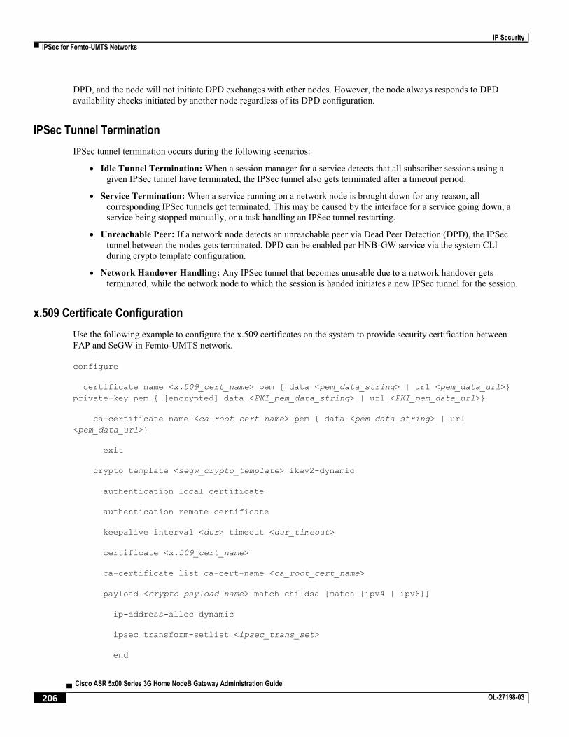
IP Security
▀ IPSec for Femto-UMTS Networks
▄ Cisco ASR 5x00 Series 3G Home NodeB Gateway Administration Guide
206 OL-27198-03
DPD, and the node will not initiate DPD exchanges with other nodes. However, the node always responds to DPD
availability checks initiated by another node regardless of its DPD configuration.
IPSec Tunnel Termination
IPSec tunnel termination occurs during the following scenarios:
Idle Tunnel Termination: When a session manager for a service detects that all subscriber sessions using a
given IPSec tunnel have terminated, the IPSec tunnel also gets terminated after a timeout period.
Service Termination: When a service running on a network node is brought down for any reason, all
corresponding IPSec tunnels get terminated. This may be caused by the interface for a service going down, a
service being stopped manually, or a task handling an IPSec tunnel restarting.
Unreachable Peer: If a network node detects an unreachable peer via Dead Peer Detection (DPD), the IPSec
tunnel between the nodes gets terminated. DPD can be enabled per HNB-GW service via the system CLI
during crypto template configuration.
Network Handover Handling: Any IPSec tunnel that becomes unusable due to a network handover gets
terminated, while the network node to which the session is handed initiates a new IPSec tunnel for the session.
x.509 Certificate Configuration
Use the following example to configure the x.509 certificates on the system to provide security certification between
FAP and SeGW in Femto-UMTS network.
configure
certificate name <x.509_cert_name> pem { data <pem_data_string> | url <pem_data_url>}
private-key pem { [encrypted] data <PKI_pem_data_string> | url <PKI_pem_data_url>}
ca-certificate name <ca_root_cert_name> pem { data <pem_data_string> | url
<pem_data_url>}
exit
crypto template <segw_crypto_template> ikev2-dynamic
authentication local certificate
authentication remote certificate
keepalive interval <dur> timeout <dur_timeout>
certificate <x.509_cert_name>
ca-certificate list ca-cert-name <ca_root_cert_name>
payload <crypto_payload_name> match childsa [match {ipv4 | ipv6}]
ip-address-alloc dynamic
ipsec transform-setlist <ipsec_trans_set>
end

IP Security
IPSec for Femto-UMTS Networks ▀
Cisco ASR 5x00 Series 3G Home NodeB Gateway Administration Guide ▄ OL-27198-03 207
configure
context <vpn_ctxt_name>
subscriber default
ip context-name <vpn_ctxt_name>
ip address pool name <ip_pool_name>
end
Notes:
<vpn_ctxt_name> is name of the source context in which HNB-GW service is configured.
<x.509_cert_name> is name of the x.509 certificate where PEM data <pem_data_string> and PKI
<PKI_pem_data_string> is configured.
<ca_root_cert_name> is name of the CA root certificate where PEM data <pem_data_string> is
configured for CPE.