cisco aironet six-element dual-band mimo patch … headquarters: cisco systems, inc., 170 west...
TRANSCRIPT

Cisco Aironet Six-Element Dual-Band MIMO Patch Array Antenna (AIR-ANT25137NP-R)
June 3, 2011This document describes the AIR-ANT25137NP-R antenna and provides instructions for mounting it. The antenna is a six-element, dual-band, multiple-input and multiple-output (MIMO), patch array antenna that operates in the 2.4- and 5-GHz frequency ranges. The antenna is designed for use in indoor and outdoor environments with Cisco Aironet 3502P Access Points.
The following information is provided in this document:
• Technical Specifications, page 2
• System Requirements, page 6
• Safety Instructions, page 7
• Installation Notes, page 8
• Choosing a Mounting Location, page 9
• Installing the Antenna, page 9
• Painting the Antenna, page 14
• Obtaining Documentation and Submitting a Service Request, page 16
Americas Headquarters: Cisco Systems, Inc., 170 West Tasman Drive, San Jose, CA 95134-1706 USA
Technical Specifications
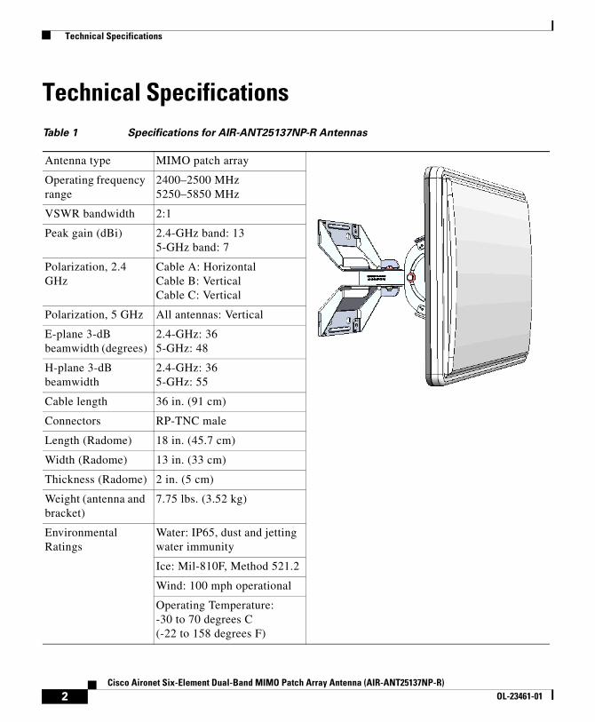
Technical SpecificationsTable 1 Specifications for AIR-ANT25137NP-R Antennas
Antenna type MIMO patch array
Operating frequency range
2400–2500 MHz5250–5850 MHz
VSWR bandwidth 2:1
Peak gain (dBi) 2.4-GHz band: 135-GHz band: 7
Polarization, 2.4 GHz
Cable A: HorizontalCable B: VerticalCable C: Vertical
Polarization, 5 GHz All antennas: Vertical
E-plane 3-dB beamwidth (degrees)
2.4-GHz: 365-GHz: 48
H-plane 3-dB beamwidth
2.4-GHz: 365-GHz: 55
Cable length 36 in. (91 cm)
Connectors RP-TNC male
Length (Radome) 18 in. (45.7 cm)
Width (Radome) 13 in. (33 cm)
Thickness (Radome) 2 in. (5 cm)
Weight (antenna and bracket)
7.75 lbs. (3.52 kg)
Environmental Ratings
Water: IP65, dust and jetting water immunity
Ice: Mil-810F, Method 521.2
Wind: 100 mph operational
Operating Temperature: -30 to 70 degrees C (-22 to 158 degrees F)
2Cisco Aironet Six-Element Dual-Band MIMO Patch Array Antenna (AIR-ANT25137NP-R)
OL-23461-01
Technical Specifications
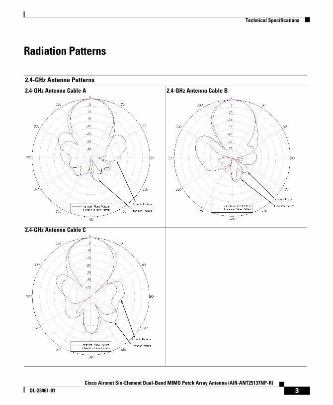
Radiation Patterns
2.4-GHz Antenna Patterns
2.4-GHz Antenna Cable A 2.4-GHz Antenna Cable B
2.4-GHz Antenna Cable C
3Cisco Aironet Six-Element Dual-Band MIMO Patch Array Antenna (AIR-ANT25137NP-R)
OL-23461-01

Technical Specifications
5-GHz Antenna Patterns
5-GHz Antenna Cable A 5-GHz Antenna Cable B
5-GHz Antenna Cable C
4Cisco Aironet Six-Element Dual-Band MIMO Patch Array Antenna (AIR-ANT25137NP-R)
OL-23461-01

Technical Specifications
Antenna and Bracket DimensionsFigure 1 and Figure 2 show the overal dimensions of the antenna and bracket.
Figure 1 Rear View of Antenna and Bracket
5Cisco Aironet Six-Element Dual-Band MIMO Patch Array Antenna (AIR-ANT25137NP-R)
OL-23461-01

System Requirements
Figure 2 Side View of Antenna and Bracket
System RequirementsThis antenna is designed for use with Cisco Aironet 3502P Access Points. The antenna can be mounted on a wall, ceiling, or pole with a maximum diameter of 3 inches (7.62 cm).
6Cisco Aironet Six-Element Dual-Band MIMO Patch Array Antenna (AIR-ANT25137NP-R)
OL-23461-01

Safety Instructions
Safety Instructions
Warning IMPORTANT SAFETY INSTRUCTIONS
This warning symbol means danger. You are in a situation that could cause bodily injury. Before you work on any equipment, be aware of the hazards involved with electrical circuitry and be familiar with standard practices for preventing accidents. Use the statement number provided at the end of each warning to locate its translation in the translated safety warnings that accompanied this device. Statement 1071
SAVE THESE INSTRUCTIONS
Warning Only trained and qualified personnel should be allowed to install, replace, or service this equipment.Statement 1030
Warning In order to comply with radio frequency (RF) exposure limits, the antennas for this product should be positioned no less than 6.56 ft (2 m) from your body or nearby persons. Statement 339
Follow these safety instructions when installing your antenna.
• Plan your installation procedure carefully and completely before you begin.
• If you are installing an antenna for the first time, for your own safety as well as others, seek professional assistance. Consult your dealer, who can explain which mounting method to use for the location where you intend to install the antenna.
• Select your installation site with safety, as well as performance, in mind. Remember that electric power cables and telephone lines look alike. For your safety, assume that any line is an electric power line until determined otherwise.
• Call your local power company or building maintenance organization if you are unsure about cables close to your mounting location.
7Cisco Aironet Six-Element Dual-Band MIMO Patch Array Antenna (AIR-ANT25137NP-R)
OL-23461-01

Installation Notes
• When installing your antenna, do not use a metal ladder. Do dress properly: shoes with rubber soles and heels, rubber gloves, and a long sleeved shirt or jacket.
• If an accident or emergency occurs with the power lines, call for qualified emergency help immediately.
Installation NotesBecause antennas transmit and receive radio signals, they are susceptible to RF obstructions and common sources of interference that can reduce throughput and range of the device to which they are connected. Follow these guidelines to ensure the best possible performance:
• Mount the antenna to utilize its propagation characteristics. This antenna is designed to radiate energy in a somewhat narrow beam from the front of the antenna. It should be aimed into the intended coverage area.
• Keep the antenna away from metal obstructions such as heating and air-conditioning ducts, large ceiling trusses, building superstructures, and major power cabling runs. If necessary, use a rigid conduit to lower the antenna away from these obstructions.
• The density of the materials used in a building’s construction determines the number of walls the signal must pass through and still maintain adequate coverage. Consider the following before choosing the location to install your antenna:
– Signals penetrate paper, vinyl and drywall the easiest. A signal can penetrate five or six walls constructed of drywall or wood.
– Signals are more heavily attenuated passing through concrete and solid-wood walls.
– Signals often reflect off thick metal walls and may not penetrate at all.
• Install the antenna away from microwave ovens and 2-GHz cordless phones. These products can cause signal interference because they operate in the same frequency range as the device to which your antenna is connected.
8Cisco Aironet Six-Element Dual-Band MIMO Patch Array Antenna (AIR-ANT25137NP-R)
OL-23461-01

Choosing a Mounting Location
Choosing a Mounting LocationThe antenna should be mounted clear of any obstructions to the side or front of the enclosure. Keep in mind that this antenna should be aimed into the intended coverage area, so you should mount the antenna so that the desired mechanical tilt can be achieved. If possible, mount the antenna near the access point so you can use the shortest possible connecting cables.
Installing the AntennaYou can install the antenna on any flat surface or on a pole with a maximum diameter of 3 inches (7.62 cm). The antenna and mounting bracket are assembled and connected together when shipped. When mounting the antenna you only need to connect the bracket to the mounting surface and adjust the antenna orientation.
Tools and Equipment RequiredYou will need these tools to loosen and tighten the adjustment bolts on the bracket:
• A 10-mm wrench or socket
To mount the antenna on a wall or ceiling, you will need these supplies:
• Four mounting screws or bolts and wall anchors
Note The fasteners and mounting surface should be capable of maintaining a minimum pullout force of 150 pounds (68 kg) to support the weight of the antenna and bracket plus the potential wind loading on the antenna.
9Cisco Aironet Six-Element Dual-Band MIMO Patch Array Antenna (AIR-ANT25137NP-R)
OL-23461-01

Installing the Antenna
To mount the antenna on a pole or mast, you will need these supplies:
• Two U-bolts
Note Cisco recommends using a guillotine-style U-bolt or a U-bolt with a notched, toothed backing plate to ensure proper support and permanent positioning.
Note The pole or mast must be rigid enough to hold the weight of the antenna plus the associated forces produced by wind loads. In addition, the pole or mast must be structurally strong enough to withstand the clamping force of the U-bolts.
You may need the following tools and equipment, which are not provided:
• A drill and drill bit
• A pencil
Mounting on a Wall or CeilingFollow these steps to mount your antenna on a wall or ceiling.
Step 1 Remove the antenna and bracket from the shipping container. The antenna and bracket are attached and the bracket is locked in place to facilitate shipping.
Step 2 Use a 10-mm wrench to loosen and remove the adjustment bolt from the shipping position (Figure 3).
10Cisco Aironet Six-Element Dual-Band MIMO Patch Array Antenna (AIR-ANT25137NP-R)
OL-23461-01
Installing the Antenna
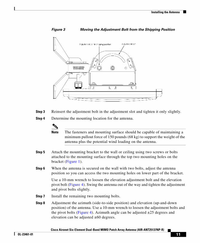
Figure 3 Moving the Adjustment Bolt from the Shipping Position
Step 3 Reinsert the adjustment bolt in the adjustment slot and tighten it only slightly.
Step 4 Determine the mounting location for the antenna.
Note The fasteners and mounting surface should be capable of maintaining a minimum pullout force of 150 pounds (68 kg) to support the weight of the antenna plus the potential wind loading on the antenna.
Step 5 Attach the mounting bracket to the wall or ceiling using two screws or bolts attached to the mounting surface through the top two mounting holes on the bracket (Figure 1).
Step 6 When the antenna is secured on the wall with two bolts, adjust the antenna position so you can access the two mounting holes on lower part of the bracket.
Use a 10-mm wrench to loosen the elevation adjustment bolt and the elevation pivot bolt (Figure 4). Swing the antenna out of the way and tighten the adjustment and pivot bolts slightly.
Step 7 Install the remaining two mounting bolts.
Step 8 Adjustment the azimuth (side-to-side position) and elevation (up-and-down position) of the antenna. Use a 10-mm wrench to loosen the adjustment bolts and the pivot bolts (Figure 4). Azimuth angle can be adjusted ±25 degrees and elevation can be adjusted ±60 degrees.
11Cisco Aironet Six-Element Dual-Band MIMO Patch Array Antenna (AIR-ANT25137NP-R)
OL-23461-01

Installing the Antenna
Step 9 After you adjust the antenna position, tighten the adjustment bolts and the pivot bolts. Tighten all bolts to 7 ± 0.5 lb-ft. (9.5 Nm).
Step 10 Connect the antenna cable to the access point.
Figure 4 Azimuth and Elevation Adjustment
12Cisco Aironet Six-Element Dual-Band MIMO Patch Array Antenna (AIR-ANT25137NP-R)
OL-23461-01

Installing the Antenna
Mounting on a Pole or MastThe antenna can be mounted on a pole or mast using two U-bolts (not provided).
Note Cisco recommends using a guillotine-style U-bolt or a U-bolt with a notched, toothed backing plate to ensure proper support and permanent positioning.
To mount the antenna on a pole or mast, follow these steps.
Note The pole or mast must be rigid enough to hold the weight of the antenna plus the associated forces produced by wind loads. In addition, the mast must be structurally strong enough to withstand the clamping force of the U-bolts.
Step 1 Follow steps 1 through 4 from “Mounting on a Wall or Ceiling”: Remove the antenna and bracket from the shipping container, move the adjustment bolt from the shipping position to the adjustment slot, and select a mounting location.
Step 2 Position the antenna, mounting bracket, and U-bolts on the mast.
Step 3 Tighten the U-bolts until the antenna is secure on the mast.
Once the antenna is secured on the mast, you can adjust the azimuth and elevation.
Step 4 To adjust the azimuth and elevation, use a 10-mm wrench to loosen the adjustment bolts and the main pivot bolt (Figure 4). Azimuth can be adjusted ±60 degrees and elevation can be adjusted ±60 degrees.
Step 5 After you adjust the antenna position, tighten the adjustment bolts and the pivot bolts. Tighten all bolts to 7 ± 0.5 lb-ft. (9.5 Nm).
Step 6 Connect the antenna cable to the access point.
13Cisco Aironet Six-Element Dual-Band MIMO Patch Array Antenna (AIR-ANT25137NP-R)
OL-23461-01

Painting the Antenna
Suggested CableCisco recommends a high-quality, low-loss cable for use with the antenna.
Note Coaxial cable loses efficiency as the frequency increases, resulting in signal loss. The cable should be kept as short as possible because cable length also determines the amount of signal loss (the longer the run, the greater the loss).
Painting the AntennaPainting the antenna and the bracket does not affect its performance if you use standard exterior-grade, oil-based or latex paint. Do not use metallic or metallic-flake paints, which will degrade antenna performance.
Note Before painting the antenna, cover the vent on the back of the antenna with masking tape to prevent clogging (Figure 5).
Cisco recommends Krylon Fusion for Plastic or Rust-Oleum for Plastic (which might require a primer coat). For best results, follow the surface preparation suggestions from the paint manufacturer.
14Cisco Aironet Six-Element Dual-Band MIMO Patch Array Antenna (AIR-ANT25137NP-R)
OL-23461-01

Painting the Antenna
Figure 5 Vent on Rear of Antenna
15Cisco Aironet Six-Element Dual-Band MIMO Patch Array Antenna (AIR-ANT25137NP-R)
OL-23461-01

Obtaining Documentation and Submitting a Service Request
Obtaining Documentation and Submitting a Service Request
For information on obtaining documentation, submitting a service request, and gathering additional information, see the monthly What’s New in Cisco Product Documentation, which also lists all new and revised Cisco technical documentation, at:
http://www.cisco.com/en/US/docs/general/whatsnew/whatsnew.html
Subscribe to the What’s New in Cisco Product Documentation as a Really Simple Syndication (RSS) feed and set content to be delivered directly to your desktop using a reader application. The RSS feeds are a free service and Cisco currently supports RSS Version 2.0.
Cisco and the Cisco Logo are trademarks of Cisco Systems, Inc. and/or its affiliates in the U.S. and other countries. A listing of Cisco's trademarks can be found at www.cisco.com/go/trademarks. Third party trademarks mentioned are the property of their respective owners. The use of the word partner does not imply a partnership relationship between Cisco and any other company. (1005R)
16Cisco Aironet Six-Element Dual-Band MIMO Patch Array Antenna (AIR-ANT25137NP-R)
OL-23461-01