cisco aironet 350 seri es bridge hardware installation guide · vii cisco aironet 350 series bridge...
TRANSCRIPT

Corporate HeadquartersCisco Systems, Inc.170 West Tasman DriveSan Jose, CA 95134-1706 USAhttp://www.cisco.comTel: 408 526-4000
800 553-NETS (6387)Fax: 408 526-4100
Cisco Aironet 350 Series Bridge Hardware Installation Guide
Text Part Number: OL-0658-01

THE SPECIFICATIONS AND INFORMATION REGARDING THE PRODUCTS IN THIS MANUAL ARE SUBJECT TO CHANGE WITHOUT NOTICE. ALL STATEMENTS, INFORMATION, AND RECOMMENDATIONS IN THIS MANUAL ARE BELIEVED TO BE ACCURATE BUT ARE PRESENTED WITHOUT WARRANTY OF ANY KIND, EXPRESS OR IMPLIED. USERS MUST TAKE FULL RESPONSIBILITY FOR THEIR APPLICATION OF ANY PRODUCTS.
THE SOFTWARE LICENSE AND LIMITED WARRANTY FOR THE ACCOMPANYING PRODUCT ARE SET FORTH IN THE INFORMATION PACKET THAT SHIPPED WITH THE PRODUCT AND ARE INCORPORATED HEREIN BY THIS REFERENCE. IF YOU ARE UNABLE TO LOCATE THE SOFTWARE LICENSE OR LIMITED WARRANTY, CONTACT YOUR CISCO REPRESENTATIVE FOR A COPY.
The following information is for FCC compliance of Class A devices: This equipment has been tested and found to comply with the limits for a Class A digital device, pursuant to part 15 of the FCC rules. These limits are designed to provide reasonable protection against harmful interference when the equipment is operated in a commercial environment. This equipment generates, uses, and can radiate radio-frequency energy and, if not installed and used in accordance with the instruction manual, may cause harmful interference to radio communications. Operation of this equipment in a residential area is likely to cause harmful interference, in which case users will be required to correct the interference at their own expense.
The following information is for FCC compliance of Class B devices: The equipment described in this manual generates and may radiate radio-frequency energy. If it is not installed in accordance with Cisco’s installation instructions, it may cause interference with radio and television reception. This equipment has been tested and found to comply with the limits for a Class B digital device in accordance with the specifications in part 15 of the FCC rules. These specifications are designed to provide reasonable protection against such interference in a residential installation. However, there is no guarantee that interference will not occur in a particular installation.
Modifying the equipment without Cisco’s written authorization may result in the equipment no longer complying with FCC requirements for Class A or Class B digital devices. In that event, your right to use the equipment may be limited by FCC regulations, and you may be required to correct any interference to radio or television communications at your own expense.
You can determine whether your equipment is causing interference by turning it off. If the interference stops, it was probably caused by the Cisco equipment or one of its peripheral devices. If the equipment causes interference to radio or television reception, try to correct the interference by using one or more of the following measures:
• Turn the television or radio antenna until the interference stops.
• Move the equipment to one side or the other of the television or radio.
• Move the equipment farther away from the television or radio.
• Plug the equipment into an outlet that is on a different circuit from the television or radio. (That is, make certain the equipment and the television or radio are on circuits controlled by different circuit breakers or fuses.)
Modifications to this product not authorized by Cisco Systems, Inc. could void the FCC approval and negate your authority to operate the product.
The Cisco implementation of TCP header compression is an adaptation of a program developed by the University of California, Berkeley (UCB) as part of UCB’s public domain version of the UNIX operating system. All rights reserved. Copyright © 1981, Regents of the University of California.
NOTWITHSTANDING ANY OTHER WARRANTY HEREIN, ALL DOCUMENT FILES AND SOFTWARE OF THESE SUPPLIERS ARE PROVIDED “AS IS” WITH ALL FAULTS. CISCO AND THE ABOVE-NAMED SUPPLIERS DISCLAIM ALL WARRANTIES, EXPRESSED OR IMPLIED, INCLUDING, WITHOUT LIMITATION, THOSE OF MERCHANTABILITY, FITNESS FOR A PARTICULAR PURPOSE AND NONINFRINGEMENT OR ARISING FROM A COURSE OF DEALING, USAGE, OR TRADE PRACTICE.
IN NO EVENT SHALL CISCO OR ITS SUPPLIERS BE LIABLE FOR ANY INDIRECT, SPECIAL, CONSEQUENTIAL, OR INCIDENTAL DAMAGES, INCLUDING, WITHOUT LIMITATION, LOST PROFITS OR LOSS OR DAMAGE TO DATA ARISING OUT OF THE USE OR INABILITY TO USE THIS MANUAL, EVEN IF CISCO OR ITS SUPPLIERS HAVE BEEN ADVISED OF THE POSSIBILITY OF SUCH DAMAGES.
Cisco Aironet 350 Series Bridge Hardware Installation GuideCopyright ©2004 Cisco Systems, Inc. All rights reserved.
CCSP, the Cisco Square Bridge logo, Cisco Unity, Follow Me Browsing, FormShare, and StackWise are trademarks of Cisco Systems, Inc.; Changing the Way We Work, Live, Play, and Learn, and iQuick Study are service marks of Cisco Systems, Inc.; and Aironet, ASIST, BPX, Catalyst, CCDA, CCDP, CCIE, CCIP, CCNA, CCNP, Cisco, the Cisco Certified Internetwork Expert logo, Cisco IOS, Cisco Press, Cisco Systems, Cisco Systems Capital, the Cisco Systems logo, Empowering the Internet Generation, Enterprise/Solver, EtherChannel, EtherFast, EtherSwitch, Fast Step, GigaDrive, GigaStack, HomeLink, Internet Quotient, IOS, IP/TV, iQ Expertise, the iQ logo, iQ Net Readiness Scorecard, LightStream, Linksys, MeetingPlace, MGX, the Networkers logo, Networking Academy, Network Registrar, Packet, PIX, Post-Routing, Pre-Routing, ProConnect, RateMUX, Registrar, ScriptShare, SlideCast, SMARTnet, StrataView Plus, SwitchProbe, TeleRouter, The Fastest Way to Increase Your Internet Quotient, TransPath, and VCO are registered trademarks of Cisco Systems, Inc. and/or its affiliates in the United States and certain other countries.
All other trademarks mentioned in this document or Website are the property of their respective owners. The use of the word partner does not imply a partnership relationship between Cisco and any other company. (0406R)
iiiCisco Aironet 350 Series Bridge Hardware Installation Guide
OL-1412-01
C O N T E N T S
Preface vii
Objectives vii
Audience vii
Organization viii
Conventions viii
Related Publications ix
Obtaining Documentation ix
Cisco.com ix
Ordering Documentation x
Documentation Feedback x
Obtaining Technical Assistance x
Cisco TAC Website x
Opening a TAC Case xi
TAC Case Priority Definitions xi
Obtaining Additional Publications and Information xi
C H A P T E R 1 Overview 1-1
Key Features 1-2
Inline Power 1-2
Antenna Connectors 1-2
Ethernet and Serial Ports 1-2
Indicator Lights 1-3
Network Configuration Examples 1-4
Root Unit on a Wired LAN 1-4
Repeater Unit That Extends Wireless Range 1-5
Bridge Operating as a Root Access Point 1-6
Bridge Specifications 1-7
C H A P T E R 2 Installation 2-1
Cautions and Warnings 2-2
Installation Guidelines 2-3
Basic Guidelines 2-3
Antenna Options 2-3
Contents
ivCisco Aironet 350 Series Bridge Hardware Installation Guide
OL-1412-01
Unpacking the Bridge 2-5
Package Contents 2-5
Connecting the Antenna Cable 2-6
Connecting the Ethernet Cables 2-6
C H A P T E R 3 Basic Configuration 3-1
Before You Start 3-2
Summary of Configuration Steps 3-2
Using the IP Setup Utility 3-2
Obtaining and Installing IPSU 3-2
Finding the Bridge’s IP Address 3-3
Setting the Bridge’s IP Address and SSID 3-4
Entering Basic Settings 3-4
Using an Internet Browser 3-5
Using the Command-Line Interface 3-8
Default Basic Settings 3-16
C H A P T E R 4 Troubleshooting 4-1
Checking the Top Panel Indicators 4-2
Checking Basic Settings 4-3
SSID 4-3
WEP Keys 4-3
Encryption Enabled/Disabled 4-4
Device Out of Range 4-4
Resetting to the Default Configuration 4-5
A P P E N D I X A Translated Safety Warnings 7
Explosive Device Proximity Warning 8
Lightning Activity Warning 9
Installation Warning 9
Circuit Breaker (15A) Warning 10
Installation and Grounding Warning 12
A P P E N D I X B Declarations of Conformity and Regulatory Information B-1
Manufacturers Federal Communication Commission Declaration of Conformity Statement B-2
Department of Communications – Canada B-3
Canadian Compliance Statement B-3
Contents
vCisco Aironet 350 Series Bridge Hardware Installation Guide
OL-1412-01
European Community, Switzerland, Norway, Iceland, and Liechtenstein B-3
Declaration of Conformity with Regard to the R&TTE Directive 1999/5/EC B-3
Declaration of Conformity for RF Exposure B-5
Guidelines for Operating Cisco Aironet Access Points and Bridges in Japan B-5
Declaration of Conformity Statements B-6
Declaration of Conformity Statement for European Union Countries B-6
A P P E N D I X C Antenna Basics C-1
Antenna System C-2
General Antenna and Safety Tips C-3
Lightning Arrestors C-3
Antenna Cable C-4
Antenna Types C-4
Basic Antenna Alignment C-5
Performing a Link Test C-6
I N D E X

Contents
viCisco Aironet 350 Series Bridge Hardware Installation Guide
OL-1412-01
viiCisco Aironet 350 Series Bridge Hardware Installation Guide
OL-1412-01
Preface
This section describes the objectives, audience, organization, and conventions of the Cisco Aironet 350 Series Bridge Hardware Installation Guide.
ObjectivesThis publication explains the steps for initial setup and configuration of the Cisco Aironet 350 Series Bridge (here after referred to as the bridge). This publication also provides troubleshooting information and detailed specifications.
AudienceThis publication is for the person installing and configuring a bridge for the first time. The installer should be familiar with network structures, terms, and concepts.

viiiCisco Aironet 350 Series Bridge Hardware Installation Guide
OL-1412-01
PrefaceOrganization
OrganizationThis guide contains the following sections:
Chapter 1, “Overview,” describes the features and specifications of bridges.
Chapter 2, “Installation,” provides basic installation instructions.
Chapter 3, “Basic Configuration,” describes how to enter basic configuration settings.
Chapter 4, “Troubleshooting,” provides solutions to potential problems encountered during setup.
Appendix A, “Translated Safety Warnings,” lists translations of the safety warnings in this publication.
Appendix B, “Declarations of Conformity and Regulatory Information,” describes the regulatory conventions to which the bridge conforms and provides guidelines for operating bridges in Japan.
Appendix C, “Antenna Basics,” provides basic antenna information.
ConventionsThis publication uses the following conventions to convey instructions and information:
• Commands and keywords are in boldface type.
Note Means reader take note. Notes contain helpful suggestions or references to materials not contained in this manual.
Caution Means reader be careful. In this situation, you might do something that could result in equipment damage or loss of data.
ixCisco Aironet 350 Series Bridge Hardware Installation Guide
OL-1412-01
PrefaceRelated Publications
Warning The warning symbol means danger. You are in a situation that could cause bodily injury. Before you work on any equipment, be aware of the hazards involved with electrical circuitry and be familiar with standard practices for preventing accidents. To see translations of the warnings that appear in this publication, refer to Appendix A in this manual.
Related PublicationsFor more information about bridges and related products, refer to the following publications:
• Quick Start Guide: Cisco Aironet 350 Series Bridge describes how to connect and power up the bridge, assign an IP address, and configure the bridge for basic operation.
• Cisco Aironet 350 Series Bridge Software Configuration Guide describes the bridge’s management system and explains how to configure the bridge.
• Release Notes for Cisco Aironet 350 Series Bridges describes features and caveats for the 350 series bridges.
• Cisco Secure Access Control Server for Windows 2000/NT Servers Version 2.6 User Guide provides complete instructions for using Cisco Secure ACS, including steps for configuring Cisco Secure ACS to support Access Points and bridges.
• Quick Start Guide: Cisco Aironet Wireless LAN Adapters describes how to install and configure PC and PCI card client adapters for use in a wireless LAN.
• Cisco Aironet Wireless LAN Adapters Hardware Installation Guide provides hardware features, physical and performance characteristics, and installation instructions for PC and PCI card client adapters.
• Cisco Aironet Wireless LAN Adapters Software Configuration Guide provides instructions for installing and using the wireless client adapter utilities.
• Mounting Instructions for the Cisco Aironet 350 Series Bridges.
Obtaining DocumentationCisco documentation and additional literature are available on Cisco.com. Cisco also provides several ways to obtain technical assistance and other technical resources. These sections explain how to obtain technical information from Cisco Systems.
Cisco.comYou can access the most current Cisco documentation on the World Wide Web at this URL:
http://www.cisco.com/univercd/home/home.htm
You can access the Cisco website at this URL:
http://www.cisco.com
International Cisco websites can be accessed from this URL:
http://www.cisco.com/public/countries_languages.shtml
xCisco Aironet 350 Series Bridge Hardware Installation Guide
OL-1412-01
PrefaceDocumentation Feedback
Ordering DocumentationYou can find instructions for ordering documentation at this URL:
http://www.cisco.com/univercd/cc/td/doc/es_inpck/pdi.htm
You can order Cisco documentation in these ways:
• Registered Cisco.com users (Cisco direct customers) can order Cisco product documentation from the Ordering tool:
http://www.cisco.com/en/US/partner/ordering/index.shtml
• Nonregistered Cisco.com users can order documentation through a local account representative by calling Cisco Systems Corporate Headquarters (California, USA) at 408 526-7208 or, elsewhere in North America, by calling 800 553-NETS (6387).
Documentation FeedbackYou can submit e-mail comments about technical documentation to [email protected].
You can submit comments by using the response card (if present) behind the front cover of your document or by writing to the following address:
Cisco SystemsAttn: Customer Document Ordering170 West Tasman DriveSan Jose, CA 95134-9883
We appreciate your comments.
Obtaining Technical AssistanceFor all customers, partners, resellers, and distributors who hold valid Cisco service contracts, the Cisco Technical Assistance Center (TAC) provides 24-hour-a-day, award-winning technical support services, online and over the phone. Cisco.com features the Cisco TAC website as an online starting point for technical assistance. If you do not hold a valid Cisco service contract, please contact your reseller.
Cisco TAC WebsiteThe Cisco TAC website provides online documents and tools for troubleshooting and resolving technical issues with Cisco products and technologies. The Cisco TAC website is available 24 hours a day, 365 days a year. The Cisco TAC website is located at this URL:
http://www.cisco.com/tac
Accessing all the tools on the Cisco TAC website requires a Cisco.com user ID and password. If you have a valid service contract but do not have a login ID or password, register at this URL:
http://tools.cisco.com/RPF/register/register.do

xiCisco Aironet 350 Series Bridge Hardware Installation Guide
OL-1412-01
PrefaceObtaining Additional Publications and Information
Opening a TAC CaseUsing the online TAC Case Open Tool is the fastest way to open P3 and P4 cases. (P3 and P4 cases are those in which your network is minimally impaired or for which you require product information.) After you describe your situation, the TAC Case Open Tool automatically recommends resources for an immediate solution. If your issue is not resolved using the recommended resources, your case will be assigned to a Cisco TAC engineer. The online TAC Case Open Tool is located at this URL:
http://www.cisco.com/tac/caseopen
For P1 or P2 cases (P1 and P2 cases are those in which your production network is down or severely degraded) or if you do not have Internet access, contact Cisco TAC by telephone. Cisco TAC engineers are assigned immediately to P1 and P2 cases to help keep your business operations running smoothly.
To open a case by telephone, use one of the following numbers:
Asia-Pacific: +61 2 8446 7411 (Australia: 1 800 805 227) EMEA: +32 2 704 55 55 USA: 1 800 553-2447
For a complete listing of Cisco TAC contacts, go to this URL:
http://www.cisco.com/warp/public/687/Directory/DirTAC.shtml
TAC Case Priority DefinitionsTo ensure that all cases are reported in a standard format, Cisco has established case priority definitions.
Priority 1 (P1)—Your network is “down” or there is a critical impact to your business operations. You and Cisco will commit all necessary resources around the clock to resolve the situation.
Priority 2 (P2)—Operation of an existing network is severely degraded, or significant aspects of your business operation are negatively affected by inadequate performance of Cisco products. You and Cisco will commit full-time resources during normal business hours to resolve the situation.
Priority 3 (P3)—Operational performance of your network is impaired, but most business operations remain functional. You and Cisco will commit resources during normal business hours to restore service to satisfactory levels.
Priority 4 (P4)—You require information or assistance with Cisco product capabilities, installation, or configuration. There is little or no effect on your business operations.
Obtaining Additional Publications and InformationInformation about Cisco products, technologies, and network solutions is available from various online and printed sources.
• Cisco Marketplace provides a variety of Cisco books, reference guides, and logo merchandise. Go to this URL to visit the company store:
http://www.cisco.com/go/marketplace/
• The Cisco Product Catalog describes the networking products offered by Cisco Systems, as well as ordering and customer support services. Access the Cisco Product Catalog at this URL:
http://cisco.com/univercd/cc/td/doc/pcat/

xiiCisco Aironet 350 Series Bridge Hardware Installation Guide
OL-1412-01
PrefaceObtaining Additional Publications and Information
• Cisco Press publishes a wide range of general networking, training and certification titles. Both new and experienced users will benefit from these publications. For current Cisco Press titles and other information, go to Cisco Press online at this URL:
http://www.ciscopress.com
• Packet magazine is the Cisco quarterly publication that provides the latest networking trends, technology breakthroughs, and Cisco products and solutions to help industry professionals get the most from their networking investment. Included are networking deployment and troubleshooting tips, configuration examples, customer case studies, tutorials and training, certification information, and links to numerous in-depth online resources. You can access Packet magazine at this URL:
http://www.cisco.com/packet
• iQ Magazine is the Cisco bimonthly publication that delivers the latest information about Internet business strategies for executives. You can access iQ Magazine at this URL:
http://www.cisco.com/go/iqmagazine
• Internet Protocol Journal is a quarterly journal published by Cisco Systems for engineering professionals involved in designing, developing, and operating public and private internets and intranets. You can access the Internet Protocol Journal at this URL:
http://www.cisco.com/ipj
• Training—Cisco offers world-class networking training. Current offerings in network training are listed at this URL:
http://www.cisco.com/en/US/learning/index.html

C H A P T E R
1-1Cisco Aironet 350 Series Bridge Hardware Installation Guide
OL-1412-01
1Overview
Cisco Aironet 350 Series Bridges are wireless LAN transceivers that connect two or more remote networks into a single LAN. The bridge can also be used as a rugged access point, providing network access to wireless client devices.
The bridge uses a browser-based management system, but you can also configure the bridge using a terminal emulator, a Telnet session, or Simple Network Management Protocol (SNMP).
The bridge contains a metal enclosure having adequate fire resistance and low smoke-producing characteristics suitable for operation in a building’s environmental air space in accordance with Section 300-22(c) of the NEC. The bridge also supports an extended operating temperature range suitable for use in covered outside environments.
This chapter provides information on the following topics:
• Key features
• Network configuration examples
• Bridge specifications

1-2Cisco Aironet 350 Series Bridge Hardware Installation Guide
OL-1412-01
Chapter 1 OverviewKey Features
Key FeaturesThis section describes the key features of the bridge:
• Inline power
• Antenna connectors
• Ethernet and serial ports
• Indicator lights
Inline PowerThe bridge receives power through the Ethernet cable, so you don’t need to run a separate power cord to the bridge. Plug the Ethernet cable into the Ethernet port on the back of the bridge and plug the other end into one of three possible power sources:
• A Cisco Aironet power injector
• A switch with inline power, such as the Cisco Catalyst 3524-PWR-XL switch
• A power patch panel, such as the Cisco Catalyst Inline Power Patch Panel
Note Cisco Aironet 340 series bridges rely on a separate power supply plugged into the power port on the back of the bridge.
Caution Cisco Aironet power injectors are designed for use with 350 series access points and bridges only. Using the power injector with other Ethernet-ready devices can damage the equipment.
Caution The operational voltage range for Cisco Aironet 350 series access points and bridges is 24 to 60 VDC. Higher voltage can damage the equipment.
Antenna ConnectorsThe bridge is equipped with dual reverse-polarity TNC connectors that you can use to connect to your own antennas for special applications.
Ethernet and Serial Ports
Ethernet Port
The bridge’s Ethernet port accepts an RJ-45 connector, linking the bridge to your Ethernet LAN. The 350 series bridge receives power through the Ethernet cable from a switch with inline power, from a power patch panel, or from the bridge’s power injector.

1-3Cisco Aironet 350 Series Bridge Hardware Installation Guide
OL-1412-01
Chapter 1 OverviewKey Features
Serial Port
The bridge’s serial port provides console access to its management system. Use a nine-pin, straight-through, male-to-female serial cable to connect your computer’s COM 1 or COM 2 port to the bridge’s serial port. Assign the following port settings to a terminal emulator to open the management system pages: 9600 baud, 8 data bits, No parity, 1 stop bit, and Xon/Xoff flow control.
Indicator LightsThe three indicator lights on top of the bridge report Ethernet activity, association status, and radio activity. The indicators are labeled in Figure 1-1.
Figure 1-1 Indicator Lights on the Bridge
• The Ethernet indicator signals traffic on the wired LAN, or Ethernet infrastructure. This indicator blinks green when a packet is received or transmitted over the Ethernet infrastructure.
• The status indicator signals operational status. Blinking green indicates that the bridge is operating normally but is not associated with any wireless devices. Steady green indicates that the bridge is associated with a wireless client.
For repeater bridges, blinking 1/2 on, 1/2 off indicates the repeater is not associated with the root bridge; blinking 7/8 on, 1/8 off indicates that the repeater is associated with the root bridge but no client devices are associated with the repeater; steady green indicates that the repeater is associated with the root bridge and client devices are associated with the repeater.
• The radio indicator blinks green to indicate radio traffic activity. The light is normally off, but it blinks green whenever a packet is received or transmitted over the bridge’s radio.
4876
7
CISCO AIRONET 350 SERIES
W I R E L E S S B R I D G E
ETHERNET ACTIVITY
ASSOCIATION STATUS
RADIO ACTIVITY
EthernetStatusRadio

1-4Cisco Aironet 350 Series Bridge Hardware Installation Guide
OL-1412-01
Chapter 1 OverviewNetwork Configuration Examples
Network Configuration ExamplesThis section describes the bridge’s role in three common wireless network configurations. The bridge’s default configuration is as a root unit on a wired LAN. The other examples illustrate the bridge being used as a repeater unit and as an access point.
Root Unit on a Wired LANThe typical bridge configuration consists of two or more bridges. One bridge is connected directly to the main wired LAN (referred to as a root unit) and the other bridge or bridges (referred to as non-root units) are attached to remote LAN segments (usually in different buildings). Only one bridge in a wireless LAN can be set to root, all other bridges must be set to non-root. Figure 1-2 shows a bridge acting as a root unit on a wired LAN communicating with other non-root bridges on remote LANs.
Figure 1-2 Bridges Interconnecting Wired LANs
In Figure 1-2, packets sent between the file server and Workstation B or Workstation C go through the non-root bridges over the wireless link. Data packets sent from Workstation A to the file server go through the wired LAN segment and do not go across the wireless link.
LAN segment A
LAN segment B
File server
Workstation A
Bridge(root unit)
Bridge(non-root)
Workstation B
CISCO AIRONET 350 SERIES
WIRELESS ACCESS POINTETHERNET ACTIVITY
ASSOCIATION STATUSRADIO ACTIVITY
SERIAL PORTONLINE POWER ETHERNET
LEFT
RIGHT/PRIMARY
CISCO AIRONET 350 SERIES
WIRELESS ACCESS POINTETHERNET ACTIVITY
ASSOCIATION STATUSRADIO ACTIVITY
SERIAL PORTONLINE POWER ETHERNET
LEFT
RIGHT/PRIMARY
LAN segment CBridge
(non-root)
Workstation C
CISCO AIRONET 350 SERIES
WIRELESS ACCESS POINTETHERNET ACTIVITY
ASSOCIATION STATUSRADIO ACTIVITY
SERIAL PORTONLINE POWER ETHERNET
LEFT
RIGHT/PRIMARY
5308
9
1-5Cisco Aironet 350 Series Bridge Hardware Installation Guide
OL-1412-01
Chapter 1 OverviewNetwork Configuration Examples
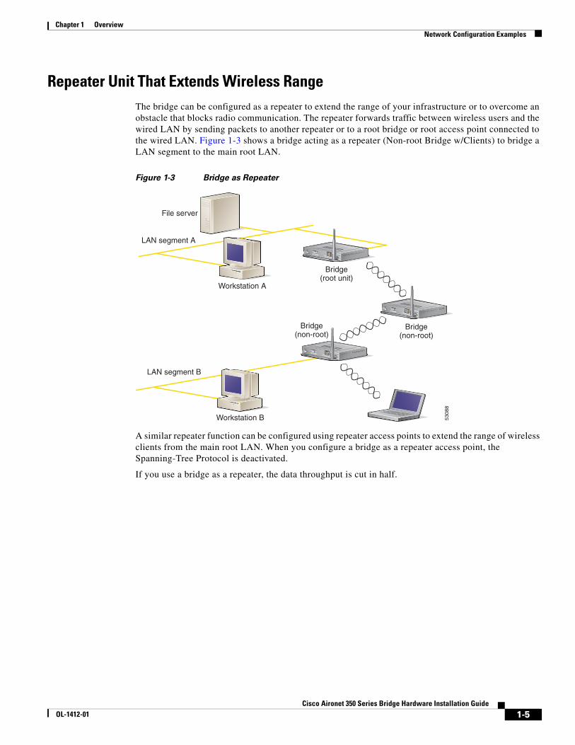
Repeater Unit That Extends Wireless RangeThe bridge can be configured as a repeater to extend the range of your infrastructure or to overcome an obstacle that blocks radio communication. The repeater forwards traffic between wireless users and the wired LAN by sending packets to another repeater or to a root bridge or root access point connected to the wired LAN. Figure 1-3 shows a bridge acting as a repeater (Non-root Bridge w/Clients) to bridge a LAN segment to the main root LAN.
Figure 1-3 Bridge as Repeater
A similar repeater function can be configured using repeater access points to extend the range of wireless clients from the main root LAN. When you configure a bridge as a repeater access point, the Spanning-Tree Protocol is deactivated.
If you use a bridge as a repeater, the data throughput is cut in half.
LAN segment A
LAN segment B
File server
Workstation A
Bridge(root unit)
Bridge(non-root)
Bridge(non-root)
Workstation B
CISCO AIRONET 350 SERIES
WIRELESS ACCESS POINTETHERNET ACTIVITY
ASSOCIATION STATUSRADIO ACTIVITY
SERIAL PORTONLINE POWER ETHERNET
LEFT
RIGHT/PRIMARY
CISCO AIRONET 350 SERIES
WIRELESS ACCESS POINTETHERNET ACTIVITY
ASSOCIATION STATUSRADIO ACTIVITY
SERIAL PORTONLINE POWER ETHERNET
LEFT
RIGHT/PRIMARY
CISCO AIRONET 350 SERIES
WIRELESS ACCESS POINTETHERNET ACTIVITY
ASSOCIATION STATUSRADIO ACTIVITY
SERIAL PORTONLINE POWER ETHERNET
LEFT
RIGHT/PRIMARY
5308
8
1-6Cisco Aironet 350 Series Bridge Hardware Installation Guide
OL-1412-01
Chapter 1 OverviewNetwork Configuration Examples
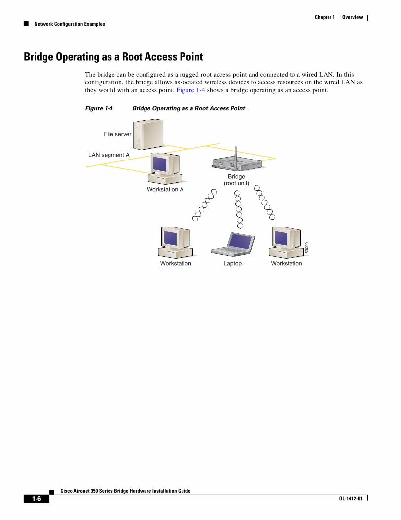
Bridge Operating as a Root Access PointThe bridge can be configured as a rugged root access point and connected to a wired LAN. In this configuration, the bridge allows associated wireless devices to access resources on the wired LAN as they would with an access point. Figure 1-4 shows a bridge operating as an access point.
Figure 1-4 Bridge Operating as a Root Access Point
LAN segment A
File server
Workstation A
Workstation WorkstationLaptop
Bridge(root unit)
CISCO AIRONET 350 SERIES
WIRELESS ACCESS POINTETHERNET ACTIVITY
ASSOCIATION STATUSRADIO ACTIVITY
SERIAL PORTONLINE POWER ETHERNET
LEFT
RIGHT/PRIMARY
5309
0

1-7Cisco Aironet 350 Series Bridge Hardware Installation Guide
OL-1412-01
Chapter 1 OverviewBridge Specifications
Bridge SpecificationsTable 1-1 lists specifications for the bridge.
Table 1-1 Bridge Specifications
Category Specification
Physical
Size 6.25 in. (15.9 cm) W x 6.42 in. (16.3 cm) D x 1.31 in. (3.3 cm) H
Status indicators Three indicators on the top panel: Ethernet traffic, status, and radio traffic
Connectors On the back panel: An RJ-45 jack for 10/100 Ethernet connections; a 9-pin serial connector; and two reverse-TNC antenna connectors
Voltage range (24 –10%) VDC to (60 –0%) VDC, nominal 48 VDC
Operating temperature range –4 to 131oF (–20 to 55oC)
32 to 104oF (0 to 40oC) for power injectors
Weight 1.43 lbs (0.64 kg)
Radio
Power output 100, 50, 30, 20, 5, or 1 mW (depending on the regulatory domain in which the bridge is installed)
Frequency 2.400 to 2.497 GHz (Depending on the regulatory domain in which the bridge is installed)
Range ( with 2.2 dBi antenna) Indoor:
150 ft at 11 Mbps
350 ft at 1 Mbps
Outdoor:
800 ft at 11 Mbps
2000 ft at 1 Mbps
Modulation Direct Sequence Spread Spectrum
Data rates 1, 2, 5.5, and 11 Mbps
Antenna Two reverse-TNC connectors (antennas are sold separately).
Compliance Operates license-free under FCC Part 15 and complies as a Class B computing device. Complies with DOC regulations. Complies with the following: ETS 300.328, FTZ 2100, MPT 1349, FCC Part 15.107 and 15.109 Class B, ICES-003 Class B (Canada), CISPR 22 Class B, AS/NZS 3548 Class B, VCCI Class B, EN 50082-1, UL1950, CSA 22.2 No. 950, EN 60950, IEC 60950, VCCI, and others (see Appendix B).
350 series bridge complies with UL 2043 for products installed in air handling spaces, such as above suspended ceilings.

1-8Cisco Aironet 350 Series Bridge Hardware Installation Guide
OL-1412-01
Chapter 1 OverviewBridge Specifications

C H A P T E R
2-1Cisco Aironet 350 Series Bridge Hardware Installation Guide
OL-1412-01
2Installation
This chapter describes the setup of the bridge and includes the following sections:
• Cautions and Warnings
• Installation Guidelines
• Unpacking the Bridge
• Connecting the Antenna Cable
• Connecting the Ethernet Cables
2-2Cisco Aironet 350 Series Bridge Hardware Installation Guide
OL-1412-01
Chapter 2 InstallationCautions and Warnings
Cautions and WarningsTranslated versions of the following safety warnings are provided in Appendix A, “Translated Safety Warnings.”
Note The FCC, with its action in ET Docket 96-8, has adopted a safety standard for human exposure to radiated frequency (RF) electromagnetic energy emitted by FCC-certified equipment. Cisco Aironet products meet the uncontrolled environmental limits found in OET-65 and ANSI C95.1, 1991. Proper operation of this radio device according to the instructions in this publication will result in user exposure substantially below the FCC recommended limits.
Caution Cisco Aironet power injectors are designed for use with 350 series access points and bridges only. Using the power injector with other Ethernet-ready devices can damage the equipment.
Caution The operational voltage range for Cisco Aironet 350 series access points and bridges is 24 to 60 VDC. Higher voltage can damage the equipment.
Warning Do not operate your wireless network device near unshielded blasting caps or in an explosive environment unless the device has been modified to be especially qualified for such use.
Warning Do not work on the system or connect or disconnect cables during periods of lightning activity.
Warning Read the installation instructions before you connect the system to its power source.
Warning This product relies on the building's installation for short-circuit (overcurrent) protection. Ensure that a fuse or circuit breaker no larger than 120 VAC, 15A U.S. (240 VAC, 10A international) is used on the phase conductors (all current-carrying conductors).
Warning Do not locate the antenna near overhead power lines or other electric light or power circuits, or where it can come into contact with such circuits. When installing the antenna, take extreme care not to come into contact with such circuits, as they may cause serious injury or death. For proper installation and grounding of the antenna, please refer to national and local codes (e.g. U.S.:NFPA 70, National Electrical Code, Article 810, in Canada: Canadian Electrical Code, Section 54).
2-3Cisco Aironet 350 Series Bridge Hardware Installation Guide
OL-1412-01
Chapter 2 InstallationInstallation Guidelines
Installation GuidelinesThis section describes things to keep in mind when installing your bridge. Sections include:
• Basic Guidelines
• Antenna Options
• Site Surveys
Basic GuidelinesBecause the bridge is a radio device, it is susceptible to common causes of interference that can reduce throughput and range. Follow these basic guidelines to ensure the best possible performance:
• Install the bridge antenna in an area where trees, buildings, or large steel structures such as shelving units, bookcases, and filing cabinets do not obstruct radio signals to and from the antenna. The antennas must be located for direct line-of-sight operation.
• Minimize the distance between the bridge and the antenna to reduce signal loss.
• Install the bridge away from microwave ovens or other devices operating in the 2.4 GHz frequency range. Microwave ovens operate on the same frequency as the bridge and can cause signal interference.
Antenna OptionsThe bridge supports external gain antennas with omni-directional or directional capabilities. Omni-directional antennas are best for systems requiring a signal distribution in more than one direction. High-gain directional antennas are best suited for covering longer distances in a fixed direction.
Site Surveys
Because of differences in component configuration, placement, and physical environment, every network application is a unique installation. Before installing multiple bridges, you should perform a site survey to determine the optimum utilization of networking components and to maximize range, coverage, and network performance.
Consider the following operating and environmental conditions when performing a site survey:
• Data rates – Sensitivity and range are inversely proportional to data bit rates. The maximum radio range is achieved at the lowest workable data rate. A decrease in receiver threshold sensitivity occurs as the radio data increases.
• Antenna type and placement – Proper antenna configuration is a critical factor in maximizing radio range. As a general rule, range increases in proportion to antenna height and gain.
• Physical environment – Clear or open areas provide better radio range than closed or filled areas. Also, the less cluttered the work environment, the greater the range.
• Obstructions – A physical obstruction such as a building or a tree can block or hinder communication between bridges. Avoid locating the antennas in a location where there is an obstruction between the sending and receiving antennas.
2-4Cisco Aironet 350 Series Bridge Hardware Installation Guide
OL-1412-01
Chapter 2 InstallationInstallation Guidelines
• Building materials – Radio penetration is greatly influenced by the building material used in construction. For example, drywall construction allows greater range than concrete blocks. Metal or steel construction is a barrier to radio signals.

2-5Cisco Aironet 350 Series Bridge Hardware Installation Guide
OL-1412-01
Chapter 2 InstallationUnpacking the Bridge
Unpacking the BridgeFollow these steps to unpack the bridge:
Step 1 Open the shipping container and carefully remove the contents.
Step 2 Return all packing materials to the shipping container and save it.
Step 3 Ensure that all items listed in the “Package Contents” section are included in the shipment. Check each item for damage.
Package ContentsEach bridge is shipped with the following items:
• Cisco Aironet 350 Series Bridge
• Nine-pin, male-to-female, straight-through serial cable
• Quick Start Guide: Cisco Aironet 350 Series Bridge
• Cisco Aironet Series Wireless Access Points and Bridges CD-ROM
• Cisco Information Packet, which contains warranty, safety, and support information
• Cisco Aironet 350 Series Power Injector and accessory kit
• Power injector
• Power cord
• Straight-through, Category 5 Ethernet cable
• Warning labels
• Plastic tie wraps, wall anchor, and screw
• Cisco product registration card
Note If any item is damaged or missing, notify your authorized Cisco sales representative.
2-6Cisco Aironet 350 Series Bridge Hardware Installation Guide
OL-1412-01
Chapter 2 InstallationConnecting the Antenna Cable
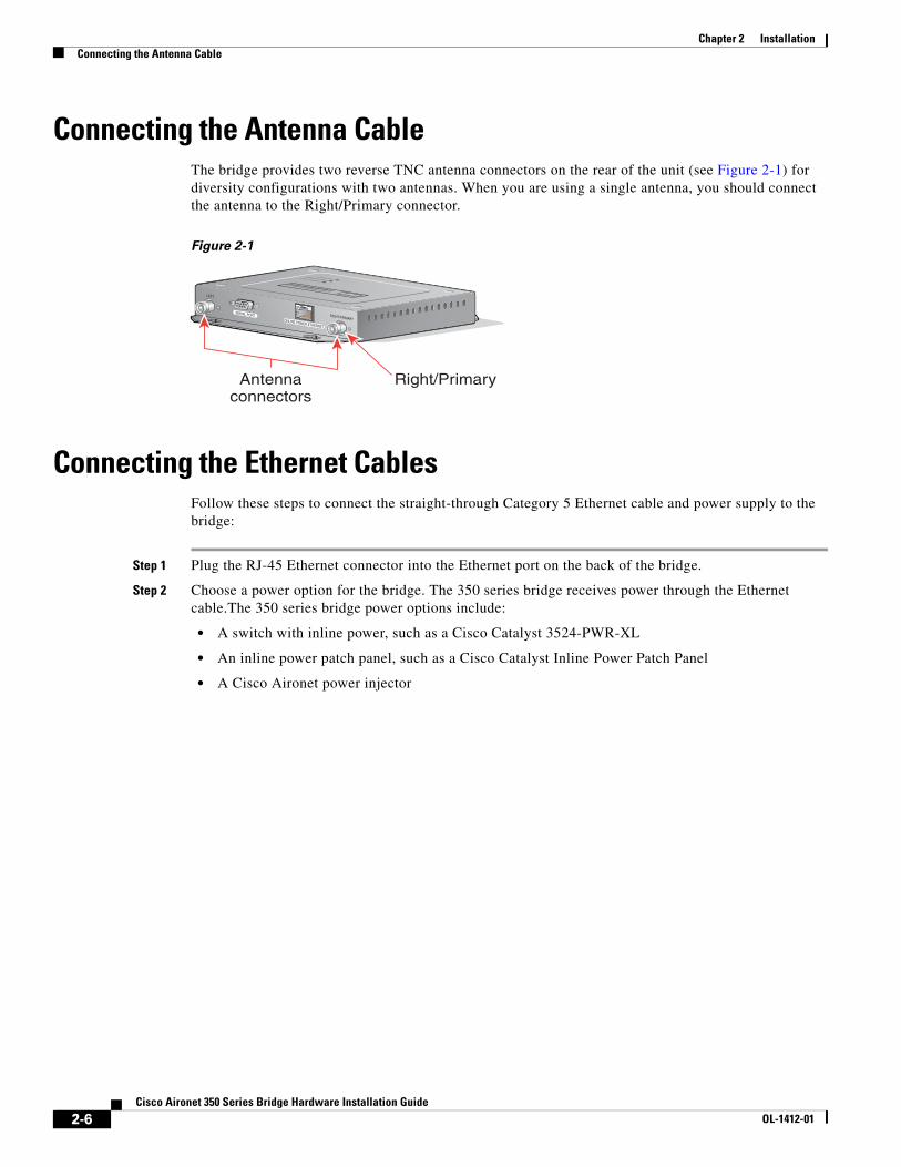
Connecting the Antenna CableThe bridge provides two reverse TNC antenna connectors on the rear of the unit (see Figure 2-1) for diversity configurations with two antennas. When you are using a single antenna, you should connect the antenna to the Right/Primary connector.
Figure 2-1
Connecting the Ethernet CablesFollow these steps to connect the straight-through Category 5 Ethernet cable and power supply to the bridge:
Step 1 Plug the RJ-45 Ethernet connector into the Ethernet port on the back of the bridge.
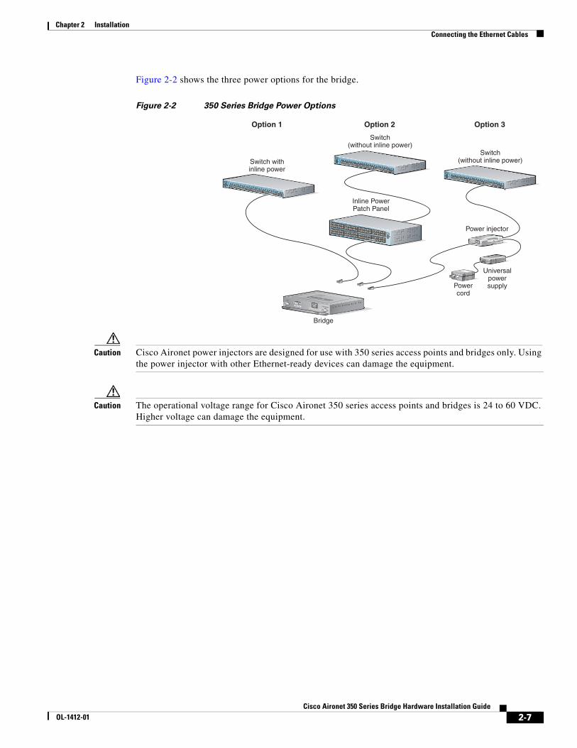
Step 2 Choose a power option for the bridge. The 350 series bridge receives power through the Ethernet cable.The 350 series bridge power options include:
• A switch with inline power, such as a Cisco Catalyst 3524-PWR-XL
• An inline power patch panel, such as a Cisco Catalyst Inline Power Patch Panel
• A Cisco Aironet power injector
CISCO AIRONET 350 SERIES
WIRELESS ACCESS POINTETHERNET ACTIVITY
ASSOCIATION STATUSRADIO ACTIVITY
SERIAL PORTONLINE POWER ETHERNET
LEFT
RIGHT/PRIMARY
Antennaconnectors
Right/Primary
2-7Cisco Aironet 350 Series Bridge Hardware Installation Guide
OL-1412-01
Chapter 2 InstallationConnecting the Ethernet Cables
Figure 2-2 shows the three power options for the bridge.
Figure 2-2 350 Series Bridge Power Options
Caution Cisco Aironet power injectors are designed for use with 350 series access points and bridges only. Using the power injector with other Ethernet-ready devices can damage the equipment.
Caution The operational voltage range for Cisco Aironet 350 series access points and bridges is 24 to 60 VDC. Higher voltage can damage the equipment.
SYSTRPS
DUPLX
MODE
SPEEDUTIL
STAT
1 2 3 4 5 6 7 89 10 11 12 13 14 15 16
17 18 19 20 21 22 23 2423 24
10Base-T / 100Base-TX
100Base-FX
Catalyst 2950 SERIES
SYSTRPS
DUPLX
MODE
SPEEDUTIL
STAT
1 2 3 4 5 6 7 89 10 11 12 13 14 15 16
17 18 19 20 21 22 23 2423 24
10Base-T / 100Base-TX
100Base-FX
Catalyst 2950 SERIES
SYSTRPS
DUPLX
MODE
SPEEDUTIL
STAT
1 2 3 4 5 6 7 89 10 11 12 13 14 15 16
17 18 19 20 21 22 23 2423 24
10Base-T / 100Base-TX
100Base-FX
Catalyst 2950 SERIES
SYSTRPS
DUPLX
MODE
SPEEDUTIL
STAT
TOAP/ BRIDGE
TO NETWORK
Switch withinline power
Power injector
Bridge
Switch(without inline power)
Switch(without inline power)
Inline PowerPatch Panel
Option 1 Option 2 Option 3
Powercord
Universalpowersupply
CISCO AIRONET 350 SERIES
WIRELESS ACCESS POINTETHERNET ACTIVITY
ASSOCIATION STATUSRADIO ACTIVITY
SERIAL PORTONLINE POWER ETHERNET
LEFT
RIGHT/PRIMARY

2-8Cisco Aironet 350 Series Bridge Hardware Installation Guide
OL-1412-01
Chapter 2 InstallationConnecting the Ethernet Cables
Step 3 Connect the other end of the Ethernet cable to the device that will supply power.
If you are using a power injector, follow these additional steps:
a. Plug the straight-through, Category 5 Ethernet cable from the bridge into the port on the power injector labeled To AP/Bridge.
Note Attach the provided warning labels to the powered Ethernet cable or the wall jack to warn other users that the Ethernet connection carries inline power.
b. Plug a straight-through, Category 5 Ethernet cable into the port on the power injector labeled To Network.
c. Plug the other end of the Ethernet cable into your 10/100 Ethernet switch, hub, or network.
d. Plug the female end of the power cord into the universal power supply.
e. Plug the male end of the power cord into a wall outlet or power strip.
f. Secure the power injector in place with the tie-wraps. Insert the tie-wraps through the slots on the bottom of the power injector and fasten the tie-wraps around a pole or a bundle of wires, or use the wall anchor and screw to secure the power injector to a wall.
At start-up, all three LEDs on the top of the bridge slowly blink amber, red, and green in sequence; the power-up sequence takes a few minutes to complete. During normal operation, the LEDs blink green. Refer to Chapter 4, “Troubleshooting,” for LED descriptions.
Step 4 Follow the steps in Chapter 3, “Basic Configuration,” to assign basic settings to the bridge.
C H A P T E R
3-1Cisco Aironet 350 Series Bridge Hardware Installation Guide
OL-1412-01
3Basic Configuration
This chapter describes interfaces you can use to initially configure your bridge with basic settings. You can use a web-browser interface, a command-line interface through a terminal emulator or a Telnet session, or a Simple Network Management Protocol (SNMP) application. Consult Chapter 2 in the Cisco Aironet 350 Series Bridge Software Configuration Guide for SNMP instructions and for complete descriptions of these interfaces.
This chapter includes the following sections:
• Before You Start
• Summary of Configuration Steps
• Using the IP Setup Utility
• Entering Basic Settings
• Default Basic Settings

3-2Cisco Aironet 350 Series Bridge Hardware Installation Guide
OL-1412-01
Chapter 3 Basic ConfigurationBefore You Start
Before You StartBefore configuring the bridge, ask your network administrator for the following information:
• The service set identifier (SSID) to be used for the bridge.
• A system name for the bridge. The name should describe the location or principal users of the bridge.
• If your network does not use DHCP to assign IP addresses, you will need an IP address for the bridge.
• If your network uses subnets, you will need a default gateway and an IP subnet mask for the bridge.
• The bridge’s MAC address, which is printed on the label on the bottom of the bridge.
Summary of Configuration StepsYou use the Express Setup page to assign basic settings to the bridge. For instructions on setting up security, filtering, and other bridge features, consult the Cisco Aironet 350 Series Bridge Software Configuration Guide on the bridge CD.
Follow these steps to enter the basic bridge settings:
1. Connect the bridge as described in the Quick Start Guide: Cisco Aironet 350 Series Bridge.
2. Use the bridge’s IP address through an Internet browser or a Telnet session to open the bridge’s management system. If your network uses a DHCP server, use the IP Setup Utility (IPSU) to find the bridge’s DHCP-assigned IP address. The “Using the IP Setup Utility” section on page 3-2 describes how to use IPSU.
You can also use a 9-pin, straight-through, male-to-female serial cable to connect your computer’s COM1 or COM2 port to the serial port on the back of the bridge and use a terminal emulator to open the management system. The “Using a Terminal Emulator” section on page 3-9 describes using a terminal emulator to assign basic settings.
3. Enter basic settings on the Express Setup page.
Using the IP Setup UtilityThe IP Setup utility (IPSU) allows you to find the bridge’s IP address when it has been assigned by a DHCP server. You can also use IPSU to set the bridge’s IP address and SSID if they have not been changed from the default settings.
Note You must run IPSU from a computer on the same subnet as the bridge.
The sections below explain how to obtain and install the utility, how to use it to find the bridge’s IP address, and how to use it to set the IP address and the SSID.
Obtaining and Installing IPSUIPSU is available on the Cisco web site. Follow these steps to obtain and install IPSU:

3-3Cisco Aironet 350 Series Bridge Hardware Installation Guide
OL-1412-01
Chapter 3 Basic ConfigurationUsing the IP Setup Utility
Step 1 Use your Internet browser to access the Cisco Software Center at the following URL:
http://www.cisco.com/public/sw-center/sw-wireless.shtml
Step 2 Locate the bridge utilities section and click on the Windows link.
Step 3 Click on the file, IPSUvxxxxx.exe. The vxxxxxx identifies the software package version number.
Step 4 Read and accept the terms and conditions of the Software License Agreement.
Step 5 Download and save the file to a temporary directory on your hard drive and then exit the Internet browser.
Step 6 Double-click IPSUvxxxxxx.exe in the temporary directory to expand the file.
Step 7 Double-click Setup.exe and follow the steps provided by the installation wizard to install IPSU.
The IPSU icon appears on your computer desktop.
Finding the Bridge’s IP AddressIf your bridge receives an IP address from a DHCP server, use IPSU to find its IP address. Follow these steps to find the bridge’s IP address:
Step 1 When the utility window opens, make sure Get IP addr is selected in the Function box.
Step 2 Enter the bridge’s MAC address in the Device MAC ID field. The bridge’s MAC address is printed on the label on the bottom of the unit. It should contain six pairs of hexadecimal digits. Your bridge’s MAC address might look like the following example:
0040963029b9
Note The MAC address field is not case-sensitive.
Step 3 Click Get IP Address.
Step 4 When the bridge’s IP address appears in the IP Address field, write it down.
If IPSU reports that the IP address is 10.0.0.1, the default IP address, then the bridge did not receive a DHCP-assigned IP address. Steps for assigning an IP address are included in the “Default IP Address” section in Chapter 3 of the Cisco Aironet 350 Series Bridge Software Configuration Guide.
Step 5 To check the IP address, browse to the bridge’s browser-based management pages. Open an Internet browser.
Step 6 Enter or paste the bridge’s IP address in the browser’s location or address field. Press Enter. The bridge’s home page appears.

3-4Cisco Aironet 350 Series Bridge Hardware Installation Guide
OL-1412-01
Chapter 3 Basic ConfigurationEntering Basic Settings
Setting the Bridge’s IP Address and SSIDIf your bridge does not receive an IP address from a DHCP server, or if you want to change the default IP address, use IPSU to assign an IP address. You can set the bridge’s SSID at the same time.
Note The computer you use to assign an IP address to the bridge must have an IP address of its own.
Note IPSU can only change the bridge’s IP address and SSID from their default settings. After the IP address and SSID have been changed, IPSU cannot change them again.
Follow these steps to assign an IP address and an SSID to the bridge:
Step 1 Double-click the IP Setup icon on your computer desktop. (If IPSU is not installed on your computer, follow the steps in the “Obtaining and Installing IPSU” section on page 3-2 to install it.)
Step 2 When the utility window opens, make sure Set Parameters is selected in the Function box.
Step 3 Enter the bridge’s MAC address in the Device MAC ID field. The bridge’s MAC address is printed on the label on the bottom of the unit. It should contain six pairs of hexadecimal digits. Your bridge’s MAC address might look like the following example:
0040963029b9
Note The MAC address field is not case-sensitive.
Step 4 Enter the IP address you want to assign to the bridge in the IP Address field.
Step 5 Enter the SSID you want to assign to the bridge in the SSID field.
Note You cannot set the SSID without also setting the IP address. You can set the IP address without setting the SSID, however.
Step 6 Click Set Parameters.
Step 7 To test the IP address, open an Internet browser.
Step 8 Enter or paste the bridge’s IP address in the browser’s location or address field. Press Enter. The bridge’s home page appears.
Entering Basic SettingsThis section provides instructions for performing a basic configuration of your bridge using your Internet browser, the bridge’s serial port, or a Telnet session.
Note Consult Chapter 2 in the Cisco Aironet 350 Series Bridge Software Configuration Guide for instructions on using SNMP to configure the bridge.

3-5Cisco Aironet 350 Series Bridge Hardware Installation Guide
OL-1412-01
Chapter 3 Basic ConfigurationEntering Basic Settings
Using an Internet BrowserThis section describes how to use your Internet browser to configure the bridge with basic settings. To quickly configure the bridge, you can enter all the bridge’s essential settings for basic operation on the Express Setup page (see Figure 3-1).
Note The bridge is compatible with Microsoft Internet Explorer versions 4.0 or later and Netscape Communicator versions 4.0 or later.
Figure 3-1 The Express Setup Page
3-6Cisco Aironet 350 Series Bridge Hardware Installation Guide
OL-1412-01
Chapter 3 Basic ConfigurationEntering Basic Settings
Follow these steps to enter basic settings with an Internet browser:
Step 1 Open your Internet browser.
Step 2 Enter or paste the bridge’s IP address in the browser’s location field. Press Enter.
Step 3 When the bridge’s Summary Status page appears, click Setup. When the Setup page appears, click Express Setup.
Note If the bridge is new and its factory configuration has not been changed, the Express Setup page appears instead of the Summary Status page when you first browse to the bridge.
Step 4 Enter a system name for the bridge in the System Name field. A descriptive system name makes it easy to identify the bridge on your network; for example: Factory Bridge.
Step 5 Select a configuration server protocol from the Configuration Server Protocol pull-down menu. The configuration server protocol you select should match your network’s method of IP address assignment. The Configuration Server link takes you to the Boot Server Setup page, which you use to configure the bridge to work with your network’s BOOTP or DHCP servers for automatic assignment of IP addresses.
Note Cisco recommends assigning a static IP address to your bridge to simplify network management and to prevent delays in receiving an address through DHCP. To assign a static IP address to your bridge, select None from the Configuration Server Protocol pull-down menu and enter the IP address for the bridge in the Default IP Address field.
The Configuration Server Protocol pull-down menu options include:
• None—This setting is used when you want to manually assign a static IP address to your bridge or your network does not have a working automatic system for IP address assignment.
• BOOTP—With Bootstrap Protocol, IP addresses are hard-coded based on MAC addresses.
• DHCP—With Dynamic Host Configuration Protocol, IP addresses are “leased” for predetermined periods of time.
Step 6 Enter an IP address in the Default IP address field. If DHCP is not enabled, the IP address you enter in this field will be the bridge’s static IP address. If DHCP or BOOTP is enabled, the address you enter in this field provides the IP address only when no server responds with an IP address for the bridge.
Step 7 Enter an IP subnet mask in the Default IP Subnet Mask field to identify the subnetwork so the bridge’s IP address can be recognized on the LAN. If DHCP or BOOTP is not enabled, this field is the subnet mask. If DHCP or BOOTP is enabled, this field provides the subnet mask only when no server responds to the bridge’s DHCP or BOOTP request.
Step 8 Enter the IP address of your default internet gateway in the Default Gateway field. The entry 255.255.255.255 indicates no gateway. Clicking the Gateway link takes you to the Routing Setup page, which you use to configure the bridge to communicate with the IP network routing system.
Step 9 Enter an SSID for the bridge in the Radio Service Set ID (SSID) field. The SSID is a unique identifier that client devices use to associate with the bridge. The SSID can be any alphanumeric entry from 2 to 32 characters long.
Step 10 Select a network role for the bridge from the Role in Radio Network pull-down menu. The menu contains the following options:

3-7Cisco Aironet 350 Series Bridge Hardware Installation Guide
OL-1412-01
Chapter 3 Basic ConfigurationEntering Basic Settings
• Root Bridge—One bridge in each group of bridges must be set as the root bridge. A root bridge only accepts associations from non-root bridges, access points, and client devices. The root bridge cannot associate with another root bridge.
• Non-Root Bridge w/Clients—Use this setting for non-root bridges that accept associations from client devices and for bridges acting as repeaters. A non-root bridge (with clients) can connect to a wired LAN. A non-root bridge (with clients) only accepts associations from non-root bridges, access points, and client devices. A non-root bridge (with clients) will only associate to another bridge (root or non-root).
Note Bridges set to non-root do not receive dynamic WEP keys for their data transmissions. Non-root bridges use the static WEP keys configured in their management systems.
• Non-Root Bridge w/o Clients—Use this setting for non-root bridges that should not accept associations from client devices. A non-root bridge (without clients) can connect to a wired LAN and only associates to another bridge (root or non-root).
• Root Access Point—Use this setting to set up the bridge as a rugged access point connected to the wired LAN. A root access point only accepts associations from non-root access points and client devices. A root access point cannot associate with another root access point or root bridge. When you select Root Access Point, the bridge’s Spanning-Tree Protocol (STP) function is disabled.
• Repeater Access Point—Use this setting to set up the bridge as a rugged repeater access point. A repeater access point is not connected to the wired LAN; it is placed within radio range of an access point connected to the wired LAN to extend the range of your infrastructure or to overcome an obstacle that blocks radio communication. A repeater access point can associate to other access points (root or repeater) and bridges (root and non-root with clients). It will accept associations from other repeater access points and client devices. When you select Repeater Access Point, the bridge’s STP function is disabled.
• Site Survey Client—Use this setting when performing a site survey for a repeater access point. When you select this setting, clients are not allowed to associate and the bridge’s STP function is disabled.
Step 11 Select an Optimize Radio Network For option to assign either preconfigured settings or customized settings for the bridge radio:
• Throughput—Maximizes the data volume handled by the bridge but might reduce the bridge’s range.
• Range—Maximizes the bridge’s range but might reduce throughput.
• Custom—The bridge will use the settings you enter on the Root Radio Hardware page. Click the Custom link to go to the Root Radio Hardware page.
Step 12 To automatically configure the bridge to be compatible with other devices on your wireless LAN, select an Ensure Compatibility With option:
• 2Mb/sec clients—Select this setting if your network contains Cisco Aironet devices that operate at 2 Mbps.
• non-Aironet 802.11—Select this setting if the bridge is operating as an access point and there are non-Cisco Aironet devices on your wireless LAN.
3-8Cisco Aironet 350 Series Bridge Hardware Installation Guide
OL-1412-01
Chapter 3 Basic ConfigurationEntering Basic Settings
Step 13 To use Simplified Network Management Protocol (SNMP), enter a community name in the SNMP Admin. Community field. This name automatically appears in the list of users authorized to view and make changes to the bridge’s management system.
Click the SNMP link to go to the SNMP Setup page, where you can edit other SNMP settings.
You can define other SNMP communities with User Management. The “Security Setup” section in Chapter 3 of the Cisco Aironet 350 Series Bridge Software Configuration Guide describes User Management.
Step 14 Click OK. The Setup page appears. If you changed the Role in Radio Network setting, your bridge reboots.
Using the Command-Line InterfaceYou can use a command-line interface (CLI) to configure your bridge through a terminal emulation program or a Telnet session instead of through your browser. This section provides instructions for Microsoft’s HyperTerminal and for Telnet; other programs are similar.
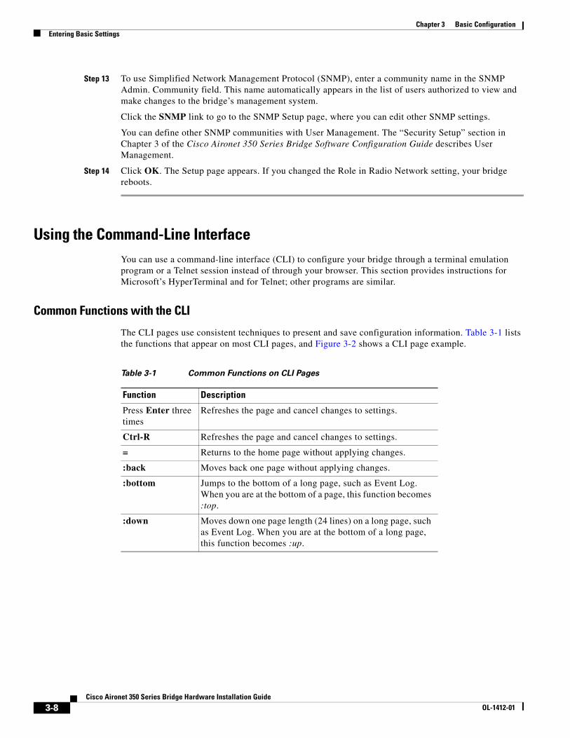
Common Functions with the CLI
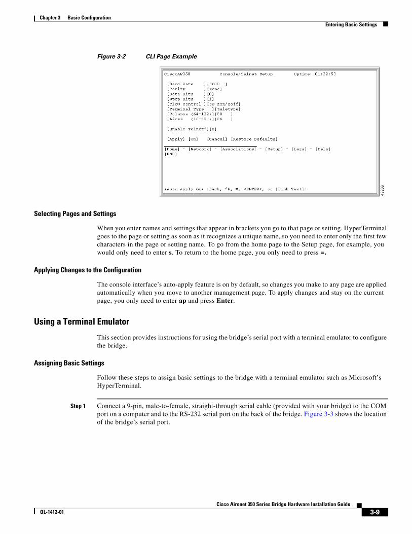
The CLI pages use consistent techniques to present and save configuration information. Table 3-1 lists the functions that appear on most CLI pages, and Figure 3-2 shows a CLI page example.
Table 3-1 Common Functions on CLI Pages
Function Description
Press Enter three times
Refreshes the page and cancel changes to settings.
Ctrl-R Refreshes the page and cancel changes to settings.
= Returns to the home page without applying changes.
:back Moves back one page without applying changes.
:bottom Jumps to the bottom of a long page, such as Event Log. When you are at the bottom of a page, this function becomes :top.
:down Moves down one page length (24 lines) on a long page, such as Event Log. When you are at the bottom of a long page, this function becomes :up.
3-9Cisco Aironet 350 Series Bridge Hardware Installation Guide
OL-1412-01
Chapter 3 Basic ConfigurationEntering Basic Settings
Figure 3-2 CLI Page Example
Selecting Pages and Settings
When you enter names and settings that appear in brackets you go to that page or setting. HyperTerminal goes to the page or setting as soon as it recognizes a unique name, so you need to enter only the first few characters in the page or setting name. To go from the home page to the Setup page, for example, you would only need to enter s. To return to the home page, you only need to press =.
Applying Changes to the Configuration
The console interface’s auto-apply feature is on by default, so changes you make to any page are applied automatically when you move to another management page. To apply changes and stay on the current page, you only need to enter ap and press Enter.
Using a Terminal Emulator
This section provides instructions for using the bridge’s serial port with a terminal emulator to configure the bridge.
Assigning Basic Settings
Follow these steps to assign basic settings to the bridge with a terminal emulator such as Microsoft’s HyperTerminal.
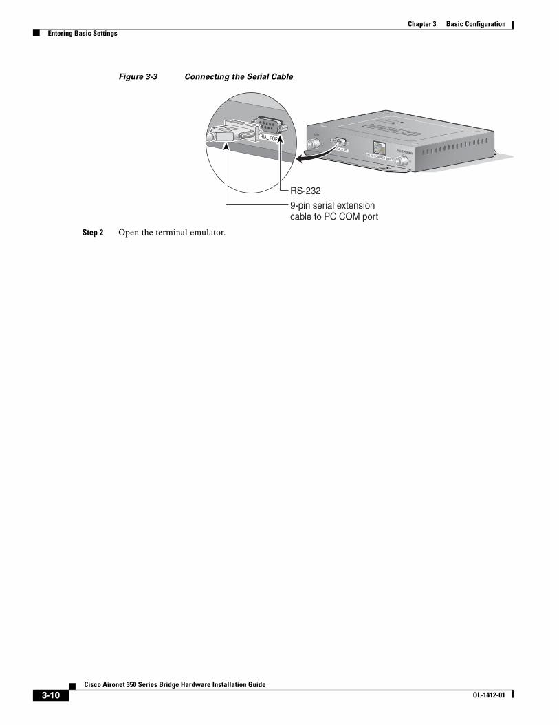
Step 1 Connect a 9-pin, male-to-female, straight-through serial cable (provided with your bridge) to the COM port on a computer and to the RS-232 serial port on the back of the bridge. Figure 3-3 shows the location of the bridge’s serial port.
3-10Cisco Aironet 350 Series Bridge Hardware Installation Guide
OL-1412-01
Chapter 3 Basic ConfigurationEntering Basic Settings
Figure 3-3 Connecting the Serial Cable
Step 2 Open the terminal emulator.
CISCO AIRONET 350 SERIES
WIRELESS ACCESS POINTETHERNET ACTIVITY
ASSOCIATION STATUSRADIO ACTIVITY
SERIAL PORTONLINE POWER ETHERNET
LEFT
RIGHT/PRIMARY
SERIAL PORT5VDC
9-pin serial extensioncable to PC COM port
RS-232
3-11Cisco Aironet 350 Series Bridge Hardware Installation Guide
OL-1412-01
Chapter 3 Basic ConfigurationEntering Basic Settings
Step 3 Enter these settings for the connection:
• Bits per second (baud rate): 9600
• Data bits: 8
• Parity: none
• Stop bits: 1
• Flow control: Xon/Xoff
Step 4 Press = to display the home page of the bridge. If the bridge is new and its factory configuration has not been changed, the Express Setup page appears; if the bridge has been configured, the Summary Status page appears.
Step 5 If you are on the Summary Status page, press s to select Setup, then press ex to select the Express Setup page.
Step 6 Press n and then press Enter to select System Name. Enter a system name for the bridge and press Enter. A descriptive system name makes it easy to identify the bridge on your network; for example: Factory Bridge.
Step 7 Press t and then press Enter to select Terminal Type. Press t to select teletype display or press a to select ANSI display for the console interface. Press Enter after you make your selection.
Step 8 Press pr and then press Enter to select Config Server Protocol.
Note Cisco recommends assigning a static IP address to your bridge to simplify network management and to prevent delays in receiving an address through DHCP. To assign a static IP address to your bridge, select None from the Configuration Server Protocol menu and enter the IP address for the bridge in the Default IP Address field.
Select one of the following options:
• Press n to select None. This setting is used when you want to manually assign a static IP address to your bridge or your network does not have a working automatic system for IP address assignment.
• Press b to select BOOTP—With Bootstrap Protocol, IP addresses are hard-coded based on MAC addresses.
• Press d to select DHCP—With Dynamic Host Configuration Protocol, IP addresses are “leased” for predetermined periods of time. Press Enter after you make your selection.
Step 9 Press ad and then press Enter to select IP Address. Enter an IP address for the bridge. If DHCP is not enabled, the IP address you enter is the bridge’s static IP address. If DHCP is enabled, the address you enter provides the IP address only when no DHCP server responds with an IP address for the bridge. Press Enter when you have completed your entry.
Step 10 Press su and then press Enter to select IP Subnet Mask. Enter an IP subnet mask to identify the subnetwork so the bridge’s IP address can be recognized on the LAN. If DHCP is not enabled, the subnet you enter is the static subnet mask. If DHCP is enabled, your entry provides the subnet mask only when no DHCP server responds to the bridge’s DHCP request. Press Enter when you have completed your entry.
Step 11 Press g and then press Enter to select Default Gateway. Enter the IP address of your default internet gateway. The entry 255.255.255.255 indicates no gateway. Press Enter when you have completed your entry.
Step 12 Press ra and then press Enter to select Radio Service Set ID (SSID). Enter an SSID for the bridge. The SSID is a unique identifier that client devices use to associate with the bridge. The SSID can be any alphanumeric entry from 2 to 32 characters long. Press Enter when you have completed your entry.

3-12Cisco Aironet 350 Series Bridge Hardware Installation Guide
OL-1412-01
Chapter 3 Basic ConfigurationEntering Basic Settings
Step 13 Press ro and then press Enter to select Role in Radio Network. The network roles include the following options:
• Root Bridge—Type root b and then press Enter to select this setting. One bridge in each group of bridges must be set as the root bridge. A root bridge only accepts associations from non-root bridges, access points, and client devices. The root bridge cannot associate with another root bridge.
• Non-Root Bridge w/Clients—Type non-root bridge w/c and then press Enter to select this setting. Use this setting for non-root bridges that accept associations from client devices and for bridges acting as repeaters. A non-root bridge (with clients) can connect to a wired LAN. A non-root bridge (with clients) only accepts associations from non-root bridges, access points, and client devices. A non-root bridge (with clients) will only associate to another bridge (root or non-root).
Note Bridges set to non-root do not receive dynamic WEP keys for their data transmissions. Non-root bridges use the static WEP keys configured in their management systems.
• Non-Root Bridge w/o Clients—Type non-root bridge w/o and then press Enter to select this setting. Use this setting for non-root bridges that should not accept associations from client devices. A non-root bridge (without clients) can connect to a wired LAN and only associates to another bridge (root or non-root).
• Root Access Point—Type root a and then press Enter to select this setting. Use this setting to set up the bridge as a rugged access point connected to the wired LAN. A root access point only accepts associations from non-root access points and client devices. A root access point cannot associate with another root access point or root bridge. When you select Root Access Point, the bridge’s Spanning-Tree Protocol (STP) function is disabled.
• Repeater Access Point—Press r and then press Enter to select this setting. Use this setting to set up the bridge as a rugged repeater access point. A repeater access point is not connected to the wired LAN; it is placed within radio range of an access point connected to the wired LAN to extend the range of your infrastructure or to overcome an obstacle that blocks radio communication. A repeater access point can associate to other access points (root or repeater) and bridges (root and non-root with clients). It will accept associations from other repeater access points and client devices. When you select Repeater Access Point, the bridge’s STP function is disabled.
• Site Survey Client—Press s and then press Enter to select this setting. Use this setting when performing a site survey for a repeater access point. When you select this setting, clients are not allowed to associate and the bridge’s STP function is disabled.
Step 14 Press op and then press Enter to select Optimize Radio Network For. These options assign either preconfigured settings or customized settings for the bridge radio:
• Throughput—Press t and then press Enter to select this setting. Maximizes the data volume handled by the bridge but might reduce the bridge’s range.
• Range—Press r and then press Enter to select this setting. Maximizes the bridge’s range but might reduce throughput.
• Custom—Press c and then press Enter to select this setting. The bridge will use the settings you enter on the Root Radio Hardware page. Chapter 3 of the Cisco Aironet 350 Series Bridge Software Configuration Guide describes the Root Radio Hardware page.
3-13Cisco Aironet 350 Series Bridge Hardware Installation Guide
OL-1412-01
Chapter 3 Basic ConfigurationEntering Basic Settings
Step 15 Use the Ensure Compatibility With setting to automatically configure the bridge to be compatible with other devices on your wireless LAN:
• 2Mb/sec clients—Press 2 and then press Enter to select this setting. Select this setting if your network contains Cisco Aironet devices that operate at 2 Mbps.
• non-Aironet 802.11—Press no and then press Enter to select this setting. Select this setting if the bridge is operating as an access point and there are non-Cisco Aironet devices on your wireless LAN.
Step 16 Press sn and then press Enter to select SNMP Admin. Community. Enter an SNMP community name. This name automatically appears in the list of users authorized to view and make changes to the bridge’s management system. Press Enter when you have completed your entry.
You can define other SNMP communities with User Management. The “Security Setup” section in Chapter 3 of the Cisco Aironet 350 Series Bridge Software Configuration Guide describes User Management.
Step 17 Press ap and press Enter to apply your basic settings. If you changed the Role in Radio Network setting, your bridge reboots.
Using a Telnet Session
This section provides instructions for using a Telnet session to configure the bridge. The Telnet interface to the bridge is the same as the terminal emulator interface, except for setting-up and closing the session.
Assigning Basic Settings
Follow these steps to assign basic settings to the bridge using a Telnet session:
Step 1 On your computer’s Start menu, select Start > Run, type Telnet followed by the bridge’s IP address and press Enter.
Step 2 Press = to display the home page of the bridge. If the bridge is new and its factory configuration has not been changed, the Express Setup page appears; if the bridge has been configured, the Summary Status page appears.
Step 3 If you are on the Summary Status page, press s to select Setup, then press ex to select the Express Setup page.
Step 4 Press n and then press Enter to select System Name. Enter a system name for the bridge and press Enter. A descriptive system name makes it easy to identify the bridge on your network; for example: Factory Bridge.
Step 5 Press t and then press Enter to select Terminal Type. Press t to select teletype display or press a to select ANSI display for the console interface. Press Enter after you make your selection.
Step 6 Press pr and then press Enter to select Config Server Protocol.
Note Cisco recommends assigning a static IP address to your bridge to simplify network management and to prevent delays in receiving an address through DHCP. To assign a static IP address to your bridge, select None from the Configuration Server Protocol menu and enter the IP address for the bridge in the Default IP Address field.
Select one of the following options:

3-14Cisco Aironet 350 Series Bridge Hardware Installation Guide
OL-1412-01
Chapter 3 Basic ConfigurationEntering Basic Settings
• Press n to select None. This setting is used when you want to manually assign a static IP address to your bridge or your network does not have a working automatic system for IP address assignment.
• Press b to select BOOTP—With Bootstrap Protocol, IP addresses are hard-coded based on MAC addresses.
• Press d to select DHCP—With Dynamic Host Configuration Protocol, IP addresses are “leased” for predetermined periods of time.
Press Enter after you make your selection.
Step 7 Press ad and then press Enter to select IP Address. Enter an IP address for the bridge. If DHCP is not enabled, the IP address you enter is the bridge’s static IP address. If DHCP is enabled, the address you enter provides the IP address only when no DHCP server responds with an IP address for the bridge. Press Enter when you have completed your entry.
Step 8 Press su and then press Enter to select IP Subnet Mask. Enter an IP subnet mask to identify the subnetwork so the bridge’s IP address can be recognized on the LAN. If DHCP is not enabled, the subnet you enter is the static subnet mask. If DHCP is enabled, your entry provides the subnet mask only when no DHCP server responds to the bridge’s DHCP request. Press Enter when you have completed your entry.
Step 9 Press g and then press Enter to select Default Gateway. Enter the IP address of your default internet gateway. The entry 255.255.255.255 indicates no gateway. Press Enter when you have completed your entry.
Step 10 Press ra and then press Enter to select Radio Service Set ID (SSID). Enter an SSID for the bridge. The SSID is a unique identifier that client devices use to associate with the bridge. The SSID can be any alphanumeric entry from 2 to 32 characters long. Press Enter when you have completed your entry.
Step 11 Press ro and then press Enter to select Role in Radio Network. The network roles include the following options:
• Root Bridge—Type root b and then press Enter to select this setting. One bridge in each group of bridges must be set as the root bridge. A root bridge only accepts associations from non-root bridges, access points, and client devices. The root bridge cannot associate with another root bridge.
• Non-Root Bridge w/Clients—Type non-root bridge w/c and then press Enter to select this setting. Use this setting for non-root bridges that accept associations from client devices and for bridges acting as repeaters. A non-root bridge (with clients) can connect to a wired LAN. A non-root bridge (with clients) only accepts associations from non-root bridges, access points, and client devices. A non-root bridge (with clients) will only associate to another bridge (root or non-root).
Note Bridges set to non-root do not receive dynamic WEP keys for their data transmissions. Non-root bridges use the static WEP keys configured in their management systems.
• Non-Root Bridge w/o Clients—Type non-root bridge w/o and then press Enter to select this setting. Use this setting for non-root bridges that should not accept associations from client devices. A non-root bridge (without clients) can connect to a wired LAN and only associates to another bridge (root or non-root).
• Root Access Point—Type root a and then press Enter to select this setting. Use this setting to set up the bridge as a rugged access point connected to the wired LAN. A root access point only accepts associations from non-root access points and client devices. A root access point cannot associate with another root access point or root bridge. When you select Root Access Point, the bridge’s Spanning-Tree Protocol (STP) function is disabled.
3-15Cisco Aironet 350 Series Bridge Hardware Installation Guide
OL-1412-01
Chapter 3 Basic ConfigurationEntering Basic Settings
• Repeater Access Point—Press r and then press Enter to select this setting. Use this setting to set up the bridge as a rugged repeater access point. A repeater access point is not connected to the wired LAN; it is placed within radio range of an access point connected to the wired LAN to extend the range of your infrastructure or to overcome an obstacle that blocks radio communication. A repeater access point can associate to other access points (root or repeater) and bridges (root and non-root with clients). It will accept associations from other repeater access points and client devices. When you select Repeater Access Point, the bridge’s STP function is disabled.
• Site Survey Client—Press s and then press Enter to select this setting. Use this setting when performing a site survey for a repeater access point. When you select this setting, clients are not allowed to associate and the bridge’s STP function is disabled.
Step 12 Press op and then press Enter to select Optimize Radio Network For. These options assign either preconfigured settings or customized settings for the bridge radio:
• Throughput—Press t and then press Enter to select this setting. Maximizes the data volume handled by the bridge but might reduce the bridge’s range.
• Range—Press r and then press Enter to select this setting. Maximizes the bridge’s range but might reduce throughput.
• Custom—Press c and then press Enter to select this setting. The bridge will use the settings you enter on the Root Radio Hardware page. Chapter 3 of the Cisco Aironet 350 Series Bridge Software Configuration Guide describes the Root Radio Hardware page.
Step 13 Use the Ensure Compatibility With setting to automatically configure the bridge to be compatible with other devices on your wireless LAN:
• 2Mb/sec clients—Press 2 and then press Enter to select this setting. Select this setting if your network contains Cisco Aironet devices that operate at 2 Mbps.
• non-Aironet 802.11—Press no and then press Enter to select this setting. Select this setting if the bridge is operating as an access point and there are non-Cisco Aironet devices on your wireless LAN.

3-16Cisco Aironet 350 Series Bridge Hardware Installation Guide
OL-1412-01
Chapter 3 Basic ConfigurationDefault Basic Settings
Step 14 Press sn and then press Enter to select SNMP Admin. Community. Enter an SNMP community name. This name automatically appears in the list of users authorized to view and make changes to the bridge’s management system. Press Enter when you have completed your entry.
You can define other SNMP communities with User Management. The “Security Setup” section in Chapter 3 of the Cisco Aironet 350 Series Bridge Software Configuration Guide describes User Management.
Step 15 Press ap and press Enter to apply your basic settings. If you changed the Role in Radio Network setting, your bridge reboots.
Step 16 Close your Telnet session by closing the Telnet window.
Default Basic SettingsTable 3-2 lists the default settings on the bridge’s Express Setup page.
Table 3-2 Default Settings on the Express Setup Page
Setting Name Default Value
System Name AIR-BR350_xxxxxx (the last six characters of the unit’s MAC address)
Terminal Type (Console interface only) teletype
Config Server Protocol DHCP
IP address 10.0.0.1
IP Subnet Mask 255.255.255.0
Default Gateway 255.255.255.255
SSID tsunami
Role in Radio Network Root Bridge
Optimize Radio Network For Throughput
Ensure Compatibility With (not configured)
SNMP Admin. Community (not configured)
C H A P T E R
4-1Cisco Aironet 350 Series Bridge Hardware Installation Guide
OL-1412-01
4Troubleshooting
This chapter provides troubleshooting procedures for basic problems with the bridge. For the most up-to-date, detailed troubleshooting information, refer to the Cisco TAC website at http://www.cisco.com/tac. Select Wireless LAN under Top Issues.
Sections in this chapter include:
• Checking the Top Panel Indicators
• Checking Basic Settings
• Resetting to the Default Configuration

4-2Cisco Aironet 350 Series Bridge Hardware Installation Guide
OL-1412-01
Chapter 4 TroubleshootingChecking the Top Panel Indicators
Checking the Top Panel IndicatorsIf your bridge is not communicating, check the three indicators on the top panel. You can use them to quickly assess the unit’s status. Figure 4-1 shows the indicators, and Table 4-1 lists the meanings of the indicator signals.
Figure 4-1 Indicator Lights on the Bridge
The indicator lights have the following meanings:
• The Ethernet indicator signals traffic on the wired LAN, or Ethernet infrastructure. This indicator blinks green when a packet is received or transmitted over the Ethernet infrastructure.
• The status indicator signals operational status. Blinking green indicates that the bridge is operating normally but is not associated with any wireless devices. Steady green indicates that the bridge is associated with a wireless client.
For repeater bridges, blinking 1/2 on, 1/2 off indicates the repeater is not associated with the root bridge; blinking 7/8 on, 1/8 off indicates that the repeater is associated with the root bridge but no client devices are associated with the repeater; steady green indicates that the repeater is associated with the root bridge and client devices are associated with the repeater.
• The radio indicator blinks green to indicate radio traffic activity. The light is normally off, but it blinks green whenever a packet is received or transmitted over the bridge’s radio.
4876
7
CISCO AIRONET 350 SERIES
W I R E L E S S B R I D G E
ETHERNET ACTIVITY
ASSOCIATION STATUS
RADIO ACTIVITY
EthernetStatusRadio
Table 4-1 Top Panel Indicator Signals
Message TypeRadio Indicator
StatusIndicator
EthernetIndicator Meaning
Association status Steady green
At least one wireless client device is associated with the unit.
Blinking green
Not associated with a wireless device. Check the device SSID and WEP encryption key settings. Verify that all wireless devices have identical settings.
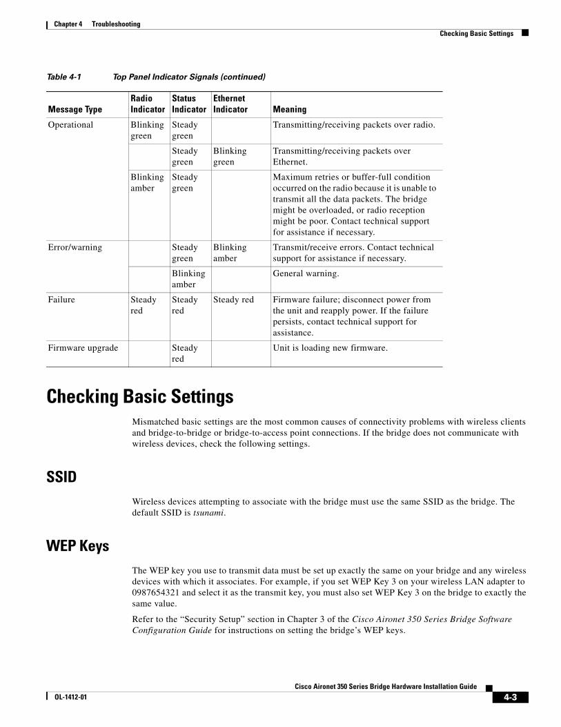
4-3Cisco Aironet 350 Series Bridge Hardware Installation Guide
OL-1412-01
Chapter 4 TroubleshootingChecking Basic Settings
Checking Basic SettingsMismatched basic settings are the most common causes of connectivity problems with wireless clients and bridge-to-bridge or bridge-to-access point connections. If the bridge does not communicate with wireless devices, check the following settings.
SSIDWireless devices attempting to associate with the bridge must use the same SSID as the bridge. The default SSID is tsunami.
WEP KeysThe WEP key you use to transmit data must be set up exactly the same on your bridge and any wireless devices with which it associates. For example, if you set WEP Key 3 on your wireless LAN adapter to 0987654321 and select it as the transmit key, you must also set WEP Key 3 on the bridge to exactly the same value.
Refer to the “Security Setup” section in Chapter 3 of the Cisco Aironet 350 Series Bridge Software Configuration Guide for instructions on setting the bridge’s WEP keys.
Operational Blinking green
Steady green
Transmitting/receiving packets over radio.
Steady green
Blinking green
Transmitting/receiving packets over Ethernet.
Blinking amber
Steady green
Maximum retries or buffer-full condition occurred on the radio because it is unable to transmit all the data packets. The bridge might be overloaded, or radio reception might be poor. Contact technical support for assistance if necessary.
Error/warning Steady green
Blinking amber
Transmit/receive errors. Contact technical support for assistance if necessary.
Blinking amber
General warning.
Failure Steady red
Steady red
Steady red Firmware failure; disconnect power from the unit and reapply power. If the failure persists, contact technical support for assistance.
Firmware upgrade Steady red
Unit is loading new firmware.
Table 4-1 Top Panel Indicator Signals (continued)
Message TypeRadio Indicator
StatusIndicator
EthernetIndicator Meaning
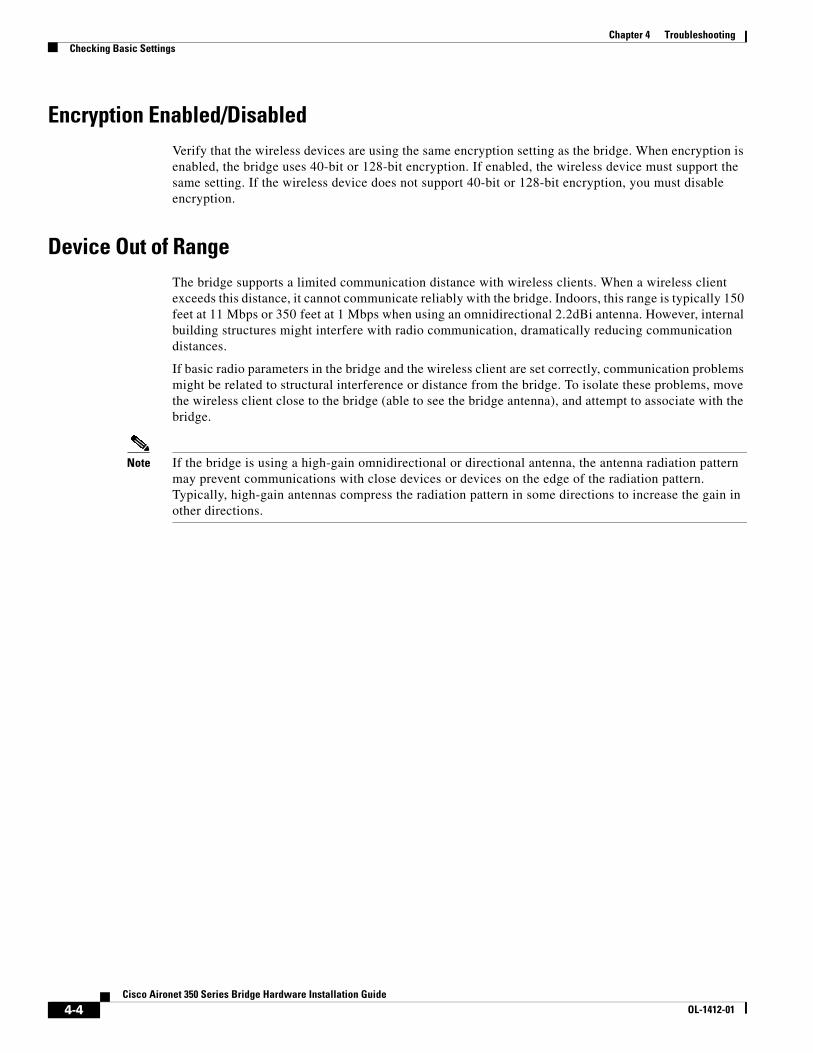
4-4Cisco Aironet 350 Series Bridge Hardware Installation Guide
OL-1412-01
Chapter 4 TroubleshootingChecking Basic Settings
Encryption Enabled/DisabledVerify that the wireless devices are using the same encryption setting as the bridge. When encryption is enabled, the bridge uses 40-bit or 128-bit encryption. If enabled, the wireless device must support the same setting. If the wireless device does not support 40-bit or 128-bit encryption, you must disable encryption.
Device Out of RangeThe bridge supports a limited communication distance with wireless clients. When a wireless client exceeds this distance, it cannot communicate reliably with the bridge. Indoors, this range is typically 150 feet at 11 Mbps or 350 feet at 1 Mbps when using an omnidirectional 2.2dBi antenna. However, internal building structures might interfere with radio communication, dramatically reducing communication distances.
If basic radio parameters in the bridge and the wireless client are set correctly, communication problems might be related to structural interference or distance from the bridge. To isolate these problems, move the wireless client close to the bridge (able to see the bridge antenna), and attempt to associate with the bridge.
Note If the bridge is using a high-gain omnidirectional or directional antenna, the antenna radiation pattern may prevent communications with close devices or devices on the edge of the radiation pattern. Typically, high-gain antennas compress the radiation pattern in some directions to increase the gain in other directions.

4-5Cisco Aironet 350 Series Bridge Hardware Installation Guide
OL-1412-01
Chapter 4 TroubleshootingResetting to the Default Configuration
Resetting to the Default ConfigurationIf you forget the password that allows you to configure the bridge you might need to completely reset the configuration. Follow these steps to delete the current configuration and return all settings to the factory defaults.
Note The following steps reset all configuration settings to factory defaults, including passwords, WEP keys, the IP address, and the SSID. If you do not need to reset the entire configuration, use the Configuration Reset buttons on the System Configuration Setup page in the web-browser interface. Consult the Cisco Aironet 350 Series Bridge Software Configuration Guide for more information on the reset buttons in the web-browser interface.
Step 1 Use a straight-through cable with 9-pin male to 9-pin female connectors to connect the COM 1 or COM 2 port on your computer to the RS-232 port on the bridge.
Step 2 Open a terminal-emulation program on your computer.
Note These instructions describe HyperTeminal; other programs are similar.
Step 3 In the Connection Description window, enter a name and select an icon for the connection and click OK.
Step 4 In the Connect To window, select the port to which the cable is connected and click OK.
Step 5 In the Port Settings window, enter the following settings:
• 9600 baud,
• 8 data bits,
• No parity,
• 1 stop bit, and
• Xon/Xoff flow control
Step 6 Click OK, and press Enter.
Step 7 When the Summary Status screen appears, reboot the bridge by unplugging the power connector and then plugging it back in.
Step 8 When the bridge reboots and the Summary Status screen reappears, type :resetall, and press Enter.
Step 9 Type yes, and press Enter to confirm the command.
Note The resetall command is valid for only 2 minutes immediately after the bridge reboots. If you do not enter and confirm the resetall command during that 2 minutes, reboot the bridge again.
Step 10 After the bridge reboots and the Express Setup screen appears, reconfigure the bridge by using the terminal emulator or an Internet browser.

4-6Cisco Aironet 350 Series Bridge Hardware Installation Guide
OL-1412-01
Chapter 4 TroubleshootingResetting to the Default Configuration

A-7Cisco Aironet 350 Series Bridge Hardware Installation Guide
OL-1412-01
A P P E N D I X ATranslated Safety Warnings
This appendix provides translations of the safety warnings that appear in this publication. These translated warnings apply to other documents in which they appear in English.
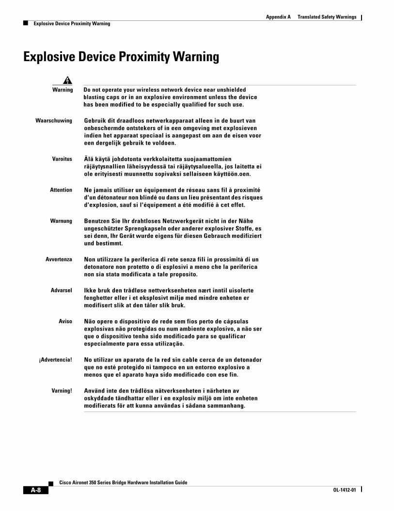
A-8Cisco Aironet 350 Series Bridge Hardware Installation Guide
OL-1412-01
Appendix A Translated Safety WarningsExplosive Device Proximity Warning
Explosive Device Proximity Warning
Warning Do not operate your wireless network device near unshielded blasting caps or in an explosive environment unless the device has been modified to be especially qualified for such use.
Waarschuwing Gebruik dit draadloos netwerkapparaat alleen in de buurt van onbeschermde ontstekers of in een omgeving met explosieven indien het apparaat speciaal is aangepast om aan de eisen voor een dergelijk gebruik te voldoen.
Varoitus Älä käytä johdotonta verkkolaitetta suojaamattomien räjäytysnallien läheisyydessä tai räjäytysalueella, jos laitetta ei ole erityisesti muunnettu sopivaksi sellaiseen käyttöön.oen.
Attention Ne jamais utiliser un équipement de réseau sans fil à proximité d'un détonateur non blindé ou dans un lieu présentant des risques d'explosion, sauf si l'équipement a été modifié à cet effet.
Warnung Benutzen Sie Ihr drahtloses Netzwerkgerät nicht in der Nähe ungeschützter Sprengkapseln oder anderer explosiver Stoffe, es sei denn, Ihr Gerät wurde eigens für diesen Gebrauch modifiziert und bestimmt.
Avvertenza Non utilizzare la periferica di rete senza fili in prossimità di un detonatore non protetto o di esplosivi a meno che la periferica non sia stata modificata a tale proposito.
Advarsel Ikke bruk den trådløse nettverksenheten nært inntil uisolerte fenghetter eller i et eksplosivt miljø med mindre enheten er modifisert slik at den tåler slik bruk.
Aviso Não opere o dispositivo de rede sem fios perto de cápsulas explosivas não protegidas ou num ambiente explosivo, a não ser que o dispositivo tenha sido modificado para se qualificar especialmente para essa utilização.
¡Advertencia! No utilizar un aparato de la red sin cable cerca de un detonador que no esté protegido ni tampoco en un entorno explosivo a menos que el aparato haya sido modificado con ese fin.
Varning! Använd inte den trådlösa nätverksenheten i närheten av oskyddade tändhattar eller i en explosiv miljö om inte enheten modifierats för att kunna användas i sådana sammanhang.
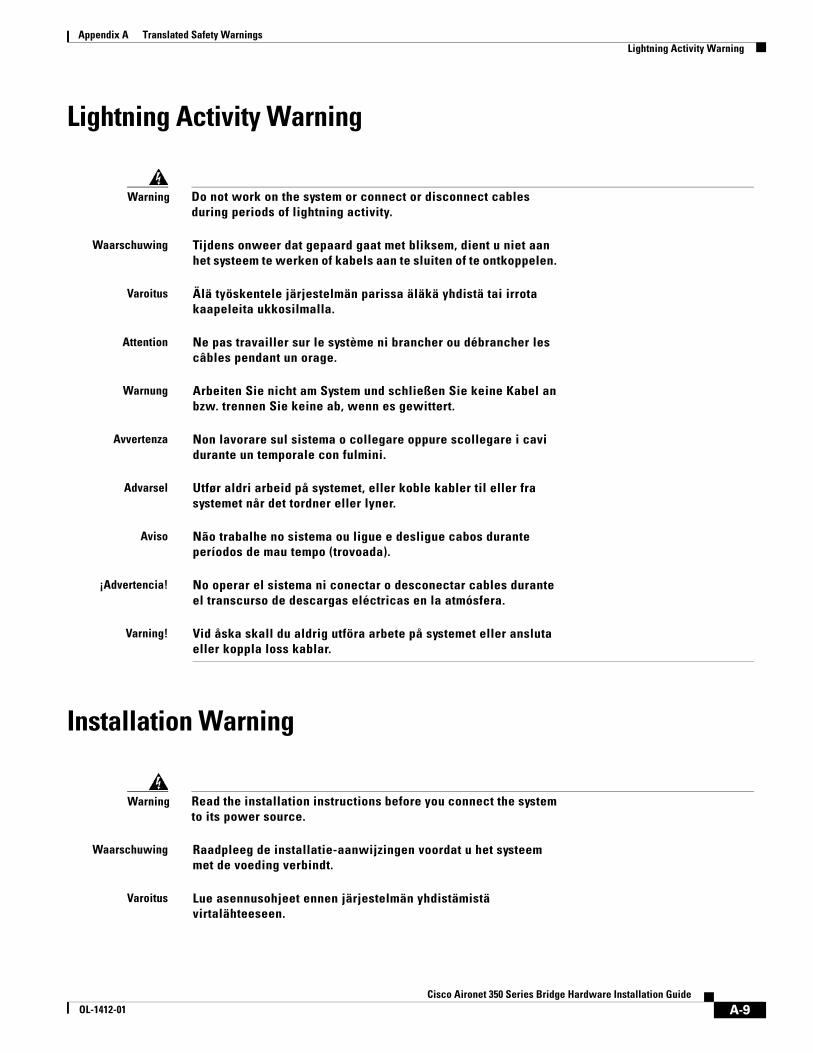
A-9Cisco Aironet 350 Series Bridge Hardware Installation Guide
OL-1412-01
Appendix A Translated Safety WarningsLightning Activity Warning
Lightning Activity Warning
Installation Warning
Warning Do not work on the system or connect or disconnect cables during periods of lightning activity.
Waarschuwing Tijdens onweer dat gepaard gaat met bliksem, dient u niet aan het systeem te werken of kabels aan te sluiten of te ontkoppelen.
Varoitus Älä työskentele järjestelmän parissa äläkä yhdistä tai irrota kaapeleita ukkosilmalla.
Attention Ne pas travailler sur le système ni brancher ou débrancher les câbles pendant un orage.
Warnung Arbeiten Sie nicht am System und schließen Sie keine Kabel an bzw. trennen Sie keine ab, wenn es gewittert.
Avvertenza Non lavorare sul sistema o collegare oppure scollegare i cavi durante un temporale con fulmini.
Advarsel Utfør aldri arbeid på systemet, eller koble kabler til eller fra systemet når det tordner eller lyner.
Aviso Não trabalhe no sistema ou ligue e desligue cabos durante períodos de mau tempo (trovoada).
¡Advertencia! No operar el sistema ni conectar o desconectar cables durante el transcurso de descargas eléctricas en la atmósfera.
Varning! Vid åska skall du aldrig utföra arbete på systemet eller ansluta eller koppla loss kablar.
Warning Read the installation instructions before you connect the system to its power source.
Waarschuwing Raadpleeg de installatie-aanwijzingen voordat u het systeem met de voeding verbindt.
Varoitus Lue asennusohjeet ennen järjestelmän yhdistämistä virtalähteeseen.

A-10Cisco Aironet 350 Series Bridge Hardware Installation Guide
OL-1412-01
Appendix A Translated Safety WarningsCircuit Breaker (15A) Warning
Circuit Breaker (15A) Warning
Attention Avant de brancher le système sur la source d'alimentation, consulter les directives d'installation.
Warnung Lesen Sie die Installationsanweisungen, bevor Sie das System an die Stromquelle anschließen.
Avvertenza Consultare le istruzioni di installazione prima di collegare il sistema all’alimentatore.
Advarsel Les installasjonsinstruksjonene før systemet kobles til strømkilden.
Aviso Leia as instruções de instalação antes de ligar o sistema à sua fonte de energia.
¡Advertencia! Ver las instrucciones de instalación antes de conectar el sistema a la red de alimentación.
Varning! Läs installationsanvisningarna innan du kopplar systemet till dess strömförsörjningsenhet.
Warning This product relies on the building’s installation for short-circuit (overcurrent) protection. Ensure that a fuse or circuit breaker no larger than 120 VAC, 15A U.S. (240 VAC, 10A international) is used on the phase conductors (all current-carrying conductors).
Waarschuwing Dit produkt is afhankelijk van de installatie van het gebouw voor kortsluit- (overstroom)beveiliging. Controleer of er een zekering of stroomverbreker van niet meer dan 120 Volt wisselstroom, 15 A voor de V.S. (240 Volt wisselstroom, 10 A internationaal) gebruikt wordt op de fasegeleiders (alle geleiders die stroom voeren).
Varoitus Tämä tuote on riippuvainen rakennukseen asennetusta oikosulkusuojauksesta (ylivirtasuojauksesta). Varmista, että vaihevirtajohtimissa (kaikissa virroitetuissa johtimissa) käytetään Yhdysvalloissa alle 120 voltin, 15 ampeerin ja monissa muissa maissa 240 voltin, 10 ampeerin sulaketta tai suojakytkintä.
Attention Pour ce qui est de la protection contre les courts-circuits (surtension), ce produit dépend de l'installation électrique du local. Vérifier qu'un fusible ou qu'un disjoncteur de 120 V alt., 15 A U.S. maximum (240 V alt., 10 A international) est utilisé sur les conducteurs de phase (conducteurs de charge).
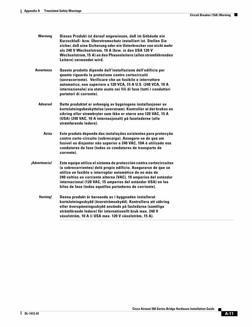
A-11Cisco Aironet 350 Series Bridge Hardware Installation Guide
OL-1412-01
Appendix A Translated Safety WarningsCircuit Breaker (15A) Warning
Warnung Dieses Produkt ist darauf angewiesen, daß im Gebäude ein Kurzschluß- bzw. Überstromschutz installiert ist. Stellen Sie sicher, daß eine Sicherung oder ein Unterbrecher von nicht mehr als 240 V Wechselstrom, 10 A (bzw. in den USA 120 V Wechselstrom, 15 A) an den Phasenleitern (allen stromführenden Leitern) verwendet wird.
Avvertenza Questo prodotto dipende dall’installazione dell’edificio per quanto riguarda la protezione contro cortocircuiti (sovracorrente). Verificare che un fusibile o interruttore automatico, non superiore a 120 VCA, 15 A U.S. (240 VCA, 10 A internazionale) sia stato usato nei fili di fase (tutti i conduttori portatori di corrente).
Advarsel Dette produktet er avhengig av bygningens installasjoner av kortslutningsbeskyttelse (overstrøm). Kontroller at det brukes en sikring eller strømbryter som ikke er større enn 120 VAC, 15 A (USA) (240 VAC, 10 A internasjonalt) på faselederne (alle strømførende ledere).
Aviso Este produto depende das instalações existentes para protecção contra curto-circuito (sobrecarga). Assegure-se de que um fusível ou disjuntor não superior a 240 VAC, 10A é utilizado nos condutores de fase (todos os condutores de transporte de corrente).
¡Advertencia! Este equipo utiliza el sistema de protección contra cortocircuitos (o sobrecorrientes) deló propio edificio. Asegurarse de que se utiliza un fusible o interruptor automático de no más de 240 voltios en corriente alterna (VAC), 10 amperios del estándar internacional (120 VAC, 15 amperios del estándar USA) en los hilos de fase (todos aquéllos portadores de corriente).
Varning! Denna produkt är beroende av i byggnaden installerat kortslutningsskydd (överströmsskydd). Kontrollera att säkring eller överspänningsskydd används på fasledarna (samtliga strömförande ledare) för internationellt bruk max. 240 V växelström, 10 A (i USA max. 120 V växelström, 15 A).
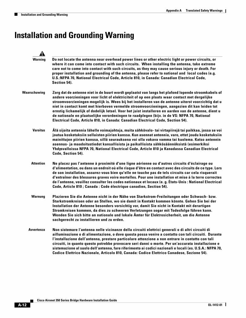
A-12Cisco Aironet 350 Series Bridge Hardware Installation Guide
OL-1412-01
Appendix A Translated Safety WarningsInstallation and Grounding Warning
Installation and Grounding Warning
Warning Do not locate the antenna near overhead power lines or other electric light or power circuits, or where it can come into contact with such circuits. When installing the antenna, take extreme care not to come into contact with such circuits, as they may cause serious injury or death. For proper installation and grounding of the antenna, please refer to national and local codes (e.g. U.S.:NFPA 70, National Electrical Code, Article 810, in Canada: Canadian Electrical Code, Section 54).
Waarschuwing Zorg dat de antenne niet in de buurt wordt geplaatst van langs het plafond lopende stroomkabels of andere voorzieningen voor licht of elektriciteit of op een plaats waar contact met dergelijke stroomvoorzieningen mogelijk is. Wees bij het installeren van de antenne uiterst voorzichtig dat u niet in contact komt met hierboven vermelde stroomvoorzieningen, aangezien dit kan leiden tot ernstig lichamelijk of dodelijk letsel. Voor het juist installeren en aarden van de antenne, dient u de nationale en plaatselijke verordeningen te raadplegen (bijv. in de VS: NFPA 70, National Electrical Code, Article 810, in Canada: Canadian Electrical Code, Section 54).
Varoitus Älä sijoita antennia lähelle voimajohtoja, muita sähkövalo- tai virtapiirejä tai paikkaa, jossa se voi joutua kosketuksiin sellaisten piirien kanssa. Kun asennat antennia, varo, ettet joudu kosketuksiin mainittujen piirien kanssa, sillä seurauksena voi olla vakava vamma tai kuolema. Katso antennin asennus- ja maadoitustiedot kansallisista ja paikallisista sähkösäännöksistä (esimerkiksi Yhdysvalloissa NFPA 70, National Electrical Code, Article 810 ja Kanadassa Canadian Electrical Code, Section 54).
Attention Ne placez pas l’antenne à proximité d'une ligne aérienne ou d'autres circuits d'éclairage ou d'alimentation, ou dans un endroit où elle risque d'être en contact avec des circuits de ce type. Lors de son installation, assurez-vous bien qu'elle ne touche pas de tels circuits car cela risquerait d'entraîner des blessures graves voire mortelles. Pour une installation et mise à la terre correctes de l’antenne, veuillez consulter les codes nationaux et locaux (e. g. États-Unis : National Electrical Code, Article 810 ; Canada : Code électrique canadien, Section 54).
Warnung Plazieren Sie die Antenne nicht in der Nähe von Starkstrom-Freileitungen oder Schwach- bzw. Starkstromkreisen oder an Stellen, wo sie damit in Kontakt kommen könnte. Gehen Sie bei der Installation der Antenne besonders vorsichtig vor, damit Sie nicht in Kontakt mit derartigen Stromkreisen kommen, da dies zu schweren Verletzungen sogar mit Todesfolge führen kann. Wenden Sie sich bitte an nationale und lokale Ämter für Elektrosicherheit, um die Antenne sachgerecht zu installieren und zu erden.
Avvertenza Non sistemare l’antenna nelle vicinanze della circuiti elettrici generali o di altri circuiti di ailluminazione o di alimentazione, o dove questa possa venire a contatto con tali circuiti. Durante l’installazione dell’antenna, prestare particolare attenzione a non entrare in contatto con tali circuiti, in quanto questo potrebbe provocare seri danni o morte. Per un’accurata installazione e sistemazione al suolo dell’antenna, fare riferimento ai codici nazionali e locali (es. U.S.A.: NFPA 70, Codice Elettrico Nazionale, Articolo 810, Canada: Codice Elettrico Canadese, Sezione 54).
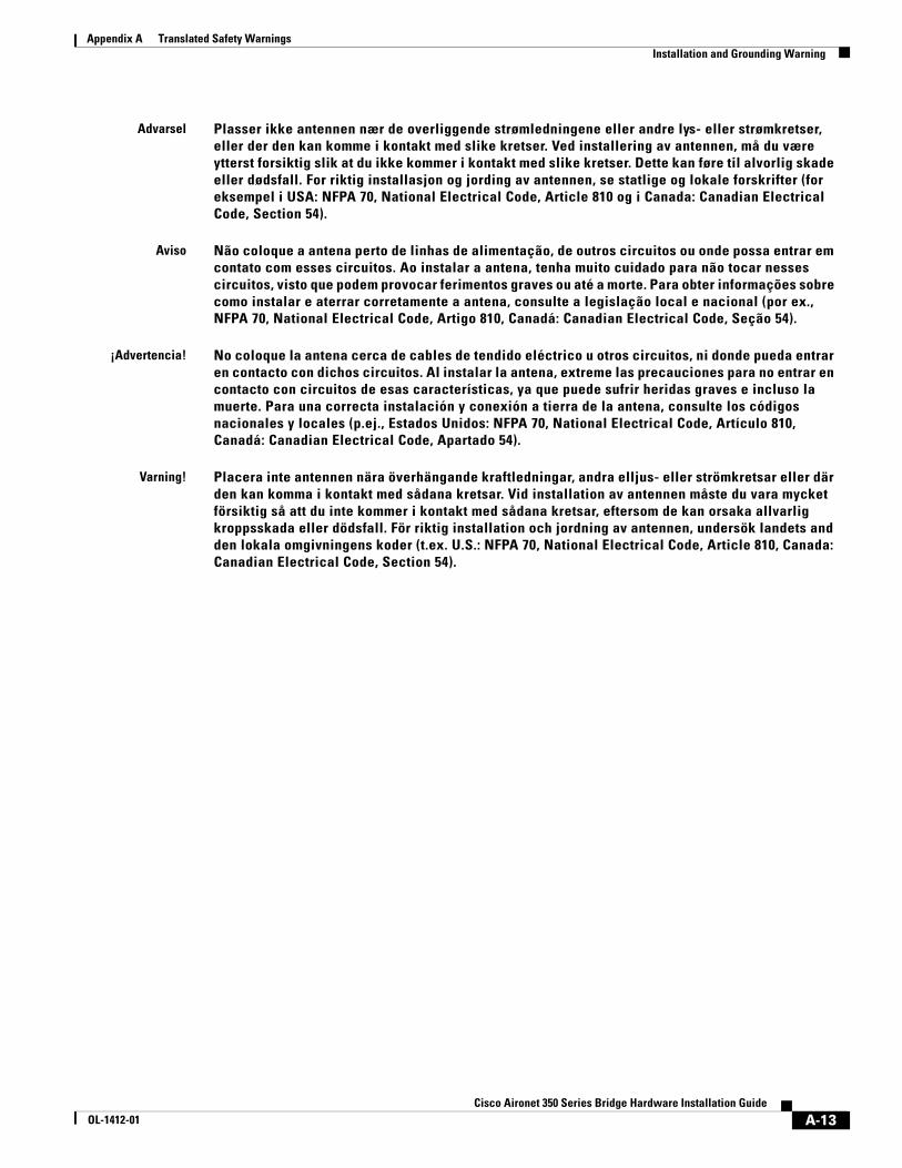
A-13Cisco Aironet 350 Series Bridge Hardware Installation Guide
OL-1412-01
Appendix A Translated Safety WarningsInstallation and Grounding Warning
Advarsel Plasser ikke antennen nær de overliggende strømledningene eller andre lys- eller strømkretser, eller der den kan komme i kontakt med slike kretser. Ved installering av antennen, må du være ytterst forsiktig slik at du ikke kommer i kontakt med slike kretser. Dette kan føre til alvorlig skade eller dødsfall. For riktig installasjon og jording av antennen, se statlige og lokale forskrifter (for eksempel i USA: NFPA 70, National Electrical Code, Article 810 og i Canada: Canadian Electrical Code, Section 54).
Aviso Não coloque a antena perto de linhas de alimentação, de outros circuitos ou onde possa entrar em contato com esses circuitos. Ao instalar a antena, tenha muito cuidado para não tocar nesses circuitos, visto que podem provocar ferimentos graves ou até a morte. Para obter informações sobre como instalar e aterrar corretamente a antena, consulte a legislação local e nacional (por ex., NFPA 70, National Electrical Code, Artigo 810, Canadá: Canadian Electrical Code, Seção 54).
¡Advertencia! No coloque la antena cerca de cables de tendido eléctrico u otros circuitos, ni donde pueda entrar en contacto con dichos circuitos. Al instalar la antena, extreme las precauciones para no entrar en contacto con circuitos de esas características, ya que puede sufrir heridas graves e incluso la muerte. Para una correcta instalación y conexión a tierra de la antena, consulte los códigos nacionales y locales (p.ej., Estados Unidos: NFPA 70, National Electrical Code, Artículo 810, Canadá: Canadian Electrical Code, Apartado 54).
Varning! Placera inte antennen nära överhängande kraftledningar, andra elljus- eller strömkretsar eller där den kan komma i kontakt med sådana kretsar. Vid installation av antennen måste du vara mycket försiktig så att du inte kommer i kontakt med sådana kretsar, eftersom de kan orsaka allvarlig kroppsskada eller dödsfall. För riktig installation och jordning av antennen, undersök landets and den lokala omgivningens koder (t.ex. U.S.: NFPA 70, National Electrical Code, Article 810, Canada: Canadian Electrical Code, Section 54).

A-14Cisco Aironet 350 Series Bridge Hardware Installation Guide
OL-1412-01
Appendix A Translated Safety WarningsInstallation and Grounding Warning

B-1Cisco Aironet 350 Series Bridge Hardware Installation Guide
OL-1412-01
A P P E N D I X BDeclarations of Conformity and Regulatory Information
This appendix provides declarations of conformity and regulatory information for Cisco Aironet access points.
This appendix contains the following sections:
• Manufacturers Federal Communication Commission Declaration of Conformity Statement
• Department of Communications – Canada
• European Community, Switzerland, Norway, Iceland, and Liechtenstein
• Declaration of Conformity for RF Exposure
• Guidelines for Operating Cisco Aironet Access Points and Bridges in Japan
• Declaration of Conformity Statements
B-2Cisco Aironet 350 Series Bridge Hardware Installation Guide
OL-1412-01
Appendix B Declarations of Conformity and Regulatory InformationManufacturers Federal Communication Commission Declaration of Conformity Statement
Manufacturers Federal Communication Commission Declaration of Conformity Statement
Models:
AIR-BR351, AIR-BR352
FCC Certification number:
LDK102040 (AIR-BR35x)
Manufacturer:
Cisco Systems, Inc.170 West Tasman DriveSan Jose, CA 95134-1706USA
This device complies with Part 15 rules. Operation is subject to the following two conditions:
1. This device may not cause harmful interference, and
2. This device must accept any interference received, including interference that may cause undesired operation.
This equipment has been tested and found to comply with the limits of a Class B digital device, pursuant to Part 15 of the FCC Rules. These limits are designed to provide reasonable protection against harmful interference when the equipment is operated in a residential environment. This equipment generates, uses, and radiates radio frequency energy, and if not installed and used in accordance with the instructions, may cause harmful interference. However, there is no guarantee that interference will not occur. If this equipment does cause interference to radio or television reception, which can be determined by turning the equipment off and on, the user is encouraged to correct the interference by one of the following measures:
• Reorient or relocate the receiving antenna.
• Increase separation between the equipment and receiver.
• Connect the equipment to an outlet on a circuit different from which the receiver is connected.
• Consult the dealer or an experienced radio/TV technician.
Caution The Part 15 radio device operates on a non-interference basis with other devices operating at this frequency. Any changes or modification to said product not expressly approved by Cisco could void the user’s authority to operate this device.
Tested To ComplyWith FCC Standards
FOR HOME OR OFFICE USE

B-3Cisco Aironet 350 Series Bridge Hardware Installation Guide
OL-1412-01
Appendix B Declarations of Conformity and Regulatory InformationDepartment of Communications – Canada
Department of Communications – Canada
Canadian Compliance StatementThis Class B Digital apparatus meets all the requirements of the Canadian Interference-Causing Equipment Regulations.
Cet appareil numerique de la classe B respecte les exigences du Reglement sur le material broilleur du Canada.
This device complies with Class B Limits of Industry Canada. Operation is subject to the following two conditions:
1. This device may not cause harmful interference, and
2. This device must accept any interference received, including interference that may cause undesired operation.
The device is certified to the requirements of RSS-139-1 and RSS-210 for 2.4-GHz spread spectrum devices. The use of this device in a system operating either partially or completely outdoors may require the user to obtain a license for the system according to the Canadian regulations. For further information, contact your local Industry Canada office.
European Community, Switzerland, Norway, Iceland, and Liechtenstein
Declaration of Conformity with Regard to the R&TTE Directive 1999/5/EC
English: This equipment is in compliance with the essential requirements and other relevant provisions of Directive 1999/5/EC.
Deutsch: Dieses Gerät entspricht den grundlegenden Anforderungen und den weiteren entsprecheneden Vorgaben der Richtlinie 1999/5/EU.
Dansk: Dette udstyr er i overensstemmelse med de væsentlige krav og andre relevante bestemmelser i Directiv 1999/5/EF.
Español: Este equipo cumple con los requisitos esenciales asi como con otras disposiciones de la Directive 1999/5/EC.
¸ëëçíáò: Áõôüò ï åîïðëéóìüò óõììïñöþíåôáé ìå ôéò ïõóéþäåéò áðáéôÞóåéò êáé ôéò ëïéðÝò äéáôÜîåéò ôçò Ïäçãßáò 1999/5/EÊ.
Français: Cet appareil est conforme aux exigencies essentialles et aux autres dispositions pertinantes de la Directive 1999/5/EC.
Íslenska: Þessi búnaður samrýmist lögboðnum kröfum og öðrum ákvæðum tilskipunar 1999/5/ESB.
B-4Cisco Aironet 350 Series Bridge Hardware Installation Guide
OL-1412-01
Appendix B Declarations of Conformity and Regulatory InformationEuropean Community, Switzerland, Norway, Iceland, and Liechtenstein
This equipment is in compliance with the essential requirements and other relevant provisions of Directive 1999/5/EC.
The Declaration of Conformity related to this product can be found at the following URL: http://www.ciscofax.com
For the 350 series, the following standards were applied:
• Radio: EN 300.328-1, EN 300.328-2
• EMC: EN 301 489-1, EN 301 489-17
• Safety: EN 60950
The following CE mark is affixed to the 350 series equipment:
The above CE mark is required as of April 8, 2000 but might change in the future.
Note This equipment is intended to be used in all EU and EFTA countries. Outdoor use may be restricted to certain frequencies and/or may require a license for operation. For more details, contact Cisco Corporate Compliance.
Note Combinations of power levels and antennas resulting in a radiated power level of above 100 mW eirp are considered as not compliant with the above mentioned directive and are not allowed for use within the European community and countries that have adopted the European R&TTE directive 1999/5/EC and/or the CEPT recommendation Rec 70.03. For more details on legal combinations of power levels and antennas, contact Cisco Corporate Compliance.
Italiano: Questo apparato é conforme ai requisiti essenziali ed agli altri principi sanciti dalla Direttiva 1999/5/EC.
Nederlands: Deze apparatuur voldoet aan de belangrijkste eisen en andere voorzieningen van richtlijn 1999/5/EC.
Norsk: Dette utstyret er i samsvar med de grunnleggende krav og andre relevante bestemmelser i EU-directiv 1999/5/EC.
Português: Este equipamento satisfaz os requisitos essenciais e outras provisões da Directiva 1999/5/EC.
Suomalainen: Tämä laite täyttää direktiivin 1999/5/EY oleelliset vaatimukset ja on siinä asetettujen muidenkin ehtojen mukainen.
Svenska: Denna utrustning är i överensstämmelse med de väsentliga kraven och andra relevanta bestämmelser i Direktiv 1999/5/EC.
5461
3
B-5Cisco Aironet 350 Series Bridge Hardware Installation Guide
OL-1412-01
Appendix B Declarations of Conformity and Regulatory InformationDeclaration of Conformity for RF Exposure
Declaration of Conformity for RF ExposureThe radio module has been evaluated under FCC Bulletin OET 65C and found compliant to the requirements as set forth in CFR 47 Sections 2.1091, 2.1093, and 15.247 (b) (4) addressing RF Exposure from radio frequency devices.
Guidelines for Operating Cisco Aironet Access Points and Bridges in Japan
This section provides guidelines for avoiding interference when operating Cisco Aironet access points and bridges in Japan. These guidelines are provided in both Japanese and English.
Japanese Translation
English Translation
This equipment operates in the same frequency bandwidth as industrial, scientific, and medical devices such as microwave ovens and mobile object identification (RF-ID) systems (licensed premises radio stations and unlicensed specified low-power radio stations) used in factory production lines.
1. Before using this equipment, make sure that no premises radio stations or specified low-power radio stations of RF-ID are used in the vicinity.
2. If this equipment causes RF interference to a premises radio station of RF-ID, promptly change the frequency or stop using the device; contact the number below and ask for recommendations on avoiding radio interference, such as setting partitions.
3. If this equipment causes RF interference to a specified low-power radio station of RF-ID, contact the number below.
Contact Number: 03-5549-6500
03-5549-6500
4376
8

B-6Cisco Aironet 350 Series Bridge Hardware Installation Guide
OL-1412-01
Appendix B Declarations of Conformity and Regulatory InformationDeclaration of Conformity Statements
Declaration of Conformity StatementsAll the Declaration of Conformity statements related to this product can be found at the following URL:
http://www.ciscofax.com
Declaration of Conformity Statement for European Union CountriesThe Declaration of Conformity statement for the European Union countries is listed below:

B-7Cisco Aironet 350 Series Bridge Hardware Installation Guide
OL-1412-01
Appendix B Declarations of Conformity and Regulatory InformationDeclaration of Conformity Statements
DECLARATION OF CONFORMITY with regard to the R&TTE Directive 1999/5/EC
according to EN 45014 Cisco Systems Inc. 170 West Tasman Drive San Jose, CA 95134 - USA
Declare under our sole responsibility that the product,
AIR-BR350 / 2.4 GHz DS 11 Mbps Ethernet Wireless Bridge Variants : AIR-BR350-E-K9, AIR-SSB350-E-K9, AIR-BR351, AIR-BR352 Note: This product is IT equipment with a built in 2,4 GHz Spread Spectrum radio
Fulfils the essential requirements of Directive 1999/5/EC. The following standards were applied on the combined equipment:
EMC (Immunity + Conducted Emissions) (Radiated Emissions)
EN 301.489-1: 2000-08; EN 301.489-17: 2000-09 EN 55022: 1998 � Class B
Health & Safety EN60950: 1992+A1+A2+A3+A4 The following standards were applied separately on the radio module:
EMC EN 301.489-1: 2000-08; EN 301.489-17: 2000-09
Health & Safety EN60950: 1992+A1+A2+A3+A4
Radio EN 300.328-1 and -2: 2000-7 The combined equipment carries the CE Mark: Additional to this CE mark, the equipment will have a sub-label (referring to the radio module): The conformity assessment procedure referred to in Article 10 and Annex IV of Directive 1999/5/EC has been followed in association with the notified body listed below:
BelcomLab, Perronstraat 6, B 8400 Oostende � Belgium. Date & Place of Issue: 12 August 2002 - Paris Signature:
Frank Dewachter - Manager Corporate Compliance EMEA 11, rue Camille Desmoulins - 92782, Issy Les Moulineaux Cedex 9 France
DofC 112808 rev3

B-8Cisco Aironet 350 Series Bridge Hardware Installation Guide
OL-1412-01
Appendix B Declarations of Conformity and Regulatory InformationDeclaration of Conformity Statements

C-1Cisco Aironet 350 Series Bridge Hardware Installation Guide
OL-1412-01
A P P E N D I X CAntenna Basics
The radio coverage of the wireless LAN supported by the bridge can be maximized with the selection of an appropriate antenna. Antennas are available with omnidirectional or directional radiation patterns and with various gain ratings. This appendix provides basic antenna information.
The following topics are covered in this section:
Antenna System
General Antenna and Safety Tips
Lightning Arrestors
Antenna Cable
Antenna Types

C-2Cisco Aironet 350 Series Bridge Hardware Installation Guide
OL-1412-01
Appendix C Antenna BasicsAntenna System
Antenna SystemDeciding which antenna to use involves many factors such as coverage area, maximum distance, indoor location, outdoor location, and antenna height.
Note In most situations, a detailed site survey along with an antenna calculation are recommended before purchasing a bridge antenna system.
Table 1 provides typical maximum communication distances between a pair of the same style antennas.
When antennas are used indoors, the building construction, ceiling height, and internal obstructions must be considered. In outdoor environments, obstructions such as trees, vehicles, buildings, and hills must be considered. Distance is a primary factor when using bridge-to-bridge communications; however, coverage area also becomes important when you are using wireless client devices to communicate with the bridge.
Table 1 Maximum Antenna Distances
Antenna Type Distance
Omnidirectional 2.2 dBi antenna Indoor—350 ft at 1 Mbps
Outdoor—2000 ft at 1 Mbps
Omnidirectional 5.2 dBi antenna 5000 ft at 2 Mbps data rate
Directional high-gain Yagi antenna 6.5 miles at 2 Mbps data rate
Directional parabolic dish antenna 25 miles at 2 Mbps data rate
C-3Cisco Aironet 350 Series Bridge Hardware Installation Guide
OL-1412-01
Appendix C Antenna BasicsAntenna System
General Antenna and Safety TipsWhen installing an antenna, follow these general tips:
• For most elevated antenna installations, it is recommended that you use professional installers for proper installation and safety.
• For safety reasons, never touch a high-gain antenna when it is transmitting or point it at any part of your body.
• Carefully follow the instructions provided with your antenna.
• Keep antennas away from metal obstructions (heating and air-conditioning ducts, large ceiling trusses, building superstructures, and major power cabling runs).
• Use a directional antenna when connecting a link between two buildings. A directional antenna must be properly aligned to directly point at the other antenna.
• Mount an omnidirectional antenna in the middle of the desired coverage area when possible.
• Place the antenna as high as possible to increase the coverage area.
• Outdoor antennas should be mounted above obstructions such as trees and buildings.
• Antenna towers should be a safe distance from overhead power lines. The recommended safe distance is twice the tower height.
• Use special ground rods and follow the National Electrical Code for proper outdoor antenna and tower grounding.
• To prevent moisture entry into the antenna cable, seal all external cable connectors using commercial products such as coax compatible electrical tape and Coax-Seal.
Lightning ArrestorsWhen you use outdoor antennas, you should use a lightning arrestor to protect radio equipment from static electricity and lightning-induced surges that travel on coaxial transmission lines. However, a lightning arrestor will not prevent damage from direct lightning strikes.
You can install the lightning arrestor indoors or outdoors. Follow the regulations or best practices applicable to lightning arrestors in your local area.
If you install the arrestor outdoors, ground the arrestor by using a ground lug attached to the arrestor and a heavy wire (#6 solid copper) and connect the lug to a good earth ground. If you install the arrestor indoors, place the wireless LAN device near a good source of ground, such as structural steel or the ground on an electrical panel, and ground the arrestor using one of those grounds. Figure 1 shows the connectors on the arrestor and the proper placement of the ground lug.
C-4Cisco Aironet 350 Series Bridge Hardware Installation Guide
OL-1412-01
Appendix C Antenna BasicsAntenna System
Figure 1 Lightning Arrestor Installation
The part number for the lightning arrestor is AIR-ACC3354. The lightning arrestor kit contains a lightning arrestor, an EMP grounding ring, and an instruction sheet. You can order the arrestor kit through your Cisco Aironet distributor.
Antenna CableAn antenna cable introduces signal losses in the antenna system for both the transmitter and receiver. To reduce signal loss, you should minimize the cable length and use only low-loss antenna cable to connect your radio device to the antenna.
Antenna TypesCisco Aironet offers several different styles of antennas in the 2.4 GHz range. Each antenna has been FCC-approved for use with the bridge. The antennas provide omnidirectional, directional, or diversity coverage and support various communication distances. Antennas are available with different gain ratings and coverage areas.
Omnidirectional Antennas
An omnidirectional antenna provides a 360-degree radiation pattern. This type of antenna is used when coverage in all directions is required and when communicating with wireless client devices. Antennas in this category are available in different gain ratings (typically 2.2 to 12 dBi).
Directional Antennas
A directional antenna provides a stronger radiation pattern in a specific direction by focusing the radiation energy to provide a greater coverage distance. Directional antennas include the Yagi antenna, the patch antenna, and the parabolic dish antenna.
To antenna
To RF device
LugLockwasher
Nut
Ground wire
3359
4
C-5Cisco Aironet 350 Series Bridge Hardware Installation Guide
OL-1412-01
Appendix C Antenna BasicsAntenna System
Parabolic dishes have very high gain (typically 21 dBi) along with a very narrow radiation angle (typically 12.5 degrees) and must be accurately aimed at the other antenna. Yagi antennas have high gain (typically 13.5 dBi) and a wider radiation angle (typically 25 to 30 degrees). Yagi antennas must also be properly aimed at the other antenna. Patch antennas have high gain (typically 6 dBi) and a relatively broad radiation angle. The patch antenna is more tolerant of orientation, but must still be positioned to face the direction of the other antenna.
Diversity Antennas
A diversity antenna is physically two antennas (sometimes in a single package) that provide diversity antenna operation. In diversity operation, the radio receives signals on both antennas but responds (transmits) on the antenna with the strongest received signal. Diversity operation helps improve system performance when signals are being reflected along different paths to the antenna. Diversity antennas for the bridge are available in 2.2 dBi and 5.2 dBi gain ratings.
Basic Antenna AlignmentWhen you are using directional antennas to communicate between two bridges, you must manually align the antennas for proper bridge operation. Directional antennas have greatly reduced radiation angles. The radiation angle for yagi antennas is approximately 25 to 30 degrees, and for parabolic dish antennas the radiation angle is approximately 12.5 degrees.
You can use the bridge link test to help measure the alignment of two antennas after the bridges are associated. The association indicates the antennas are pointing in the general vicinity of each other, but does not indicate that the antennas are properly aligned. The link test provides information you can use to gauge the alignment.
Typically, when two antennas are aligned to the edges of their radiation patterns, communication can be marginal as indicated by lost packets, high retry counts, and a low signal strength. However, when two antennas are properly aligned, communication is improved as indicated by all packets being received, lower retry counts, and a higher signal strength.
The following steps provide general guidelines for basis antenna alignment:
Step 1 Obtain the initial alignment direction. This may involve a visual line of sight for shorter distances or a Global Positioning System (GPS) receiver, map, and compass for longer distances.
Note The antennas must be located above interfering objects such as trees and buildings.
Step 2 When the antennas are initially aligned, set the bridge for a 1-Mbps data rate and check for association between the bridges.
a. From the bridge Summary Status home screen, click Setup.
b. Click Root Radio Hardware.
c. In the Data Rates selection boxes for 2.0, 5.5, and 11.0 click each of the pull down arrows and select no.
d. Click OK on the bottom of the screen, then on the pop-up message click OK to update the selections.
e. On the bridge Setup screen, click Associations to view the Association Table screen and verify that the destination bridge is listed in the Association Table.
C-6Cisco Aironet 350 Series Bridge Hardware Installation Guide
OL-1412-01
Appendix C Antenna BasicsAntenna System
Step 3 After the bridges are associated, execute a link test with the other bridge and monitor the number of successful packets, number of retries, and average signal strength. Adjust the antenna for the largest number of successful packets, the lowest number of retries, and the highest average signal strength. Refer to Performing a Link Test for additional information.
Step 4 Repeat Step 2 and Step 3 for each of the higher data rates until the antennas are adjusted at the 11-Mbps data rate.
Performing a Link TestThe link test is a valuable diagnostic tool used to check radio communication with a remote device. Typically, the link test consists of sending data packets of specified size to a destination radio, receiving the same data packet back from the destination, verifying the data, and providing status information.
Note A link test can be performed only when the two bridges are associated and use the same WEP key when WEP is enabled.
Follow these steps to initiate a bridge link test using a browser interface:
Step 1 From the bridge’s Summary Status home screen, click Associations.
Step 2 Click the MAC address of the remote bridge.
Step 3 Enter 1000 in the Link Test Count entry box to increase the number of packets used.
Step 4 Click Link Test to begin the link test operation.
When the link test completes, the results are displayed on a pop-up status screen.

IN-1Cisco Aironet 350 Series Bridge Hardware Installation Guide
OL-1412-01
I N D E X
A
antenna
connecting 2-6
considerations 2-3
maximum distance C-2
types and placement tips C-3
audience vii
B
basic settings 3-4, 3-16, 4-3
BOOTP 3-6
C
cables
antenna 2-6, C-4
Ethernet 2-6
serial 3-10
Caution viii
cautions 2-2
CLI, common functions 3-8
compliance, radio 1-7
Config Server Protocol, default 3-16
configuration
default 4-5
examples 1-4
resetting to defaults 4-5
summary 3-2
Configuration Server Protocol 3-6, 3-11, 3-13
Configuring the Bridge viii
configuring the bridge 3-1
Conformity and Regulatory information B-1
connectors 1-2, 1-7
contents, package 2-5
conventions viii
D
data rates 1-7
Declarations of Conformity and Regulatory Information
description viii
default
configuration 4-5
settings 3-16
default gateway 3-2, 3-16
DHCP 3-6, 3-11, 3-14
documentation
related publications ix
document organization viii
E
ensure compatibility setting 3-7, 3-13, 3-15
Ethernet cables, connecting 2-6
Ethernet indicator 1-3
Express Setup page 3-16
G
guidelines, installation 2-3
H
hardware installation guide

Index
IN-2Cisco Aironet 350 Series Bridge Hardware Installation Guide
OL-1412-01
audience vii
objectives vii
I
indicator lights
location 1-3
signals 4-2
inline power 1-2
Internet browser, using 3-5
IP address 3-2
IP address, default 3-16
IP Setup Utility (IPSU)
finding an IP address 3-3
installing 3-2
setting IP address and SSID 3-4
IP subnet mask 3-2
IP subnet mask, default 3-16
L
lightning arrestor C-3
M
MAC address 3-2
modulation 1-7
N
network configuration
Repeater Access Point 1-5
Root Access Point 1-6
root unit 1-4
network configuration examples 1-4
Note viii
O
optimize radio network 3-7, 3-12, 3-15
Overview
description viii
overview, product 1-1
P
password reset 4-5
ports 1-2
power
output 1-7
power injector 2-5, 2-8
power options 2-7
R
radio
indicator 1-3
network role 3-12, 3-14
output power 1-7
specifications 1-7
range 1-7
root unit 1-4
S
Safety Warnings
descriptions viii
safety warnings
circuit breaker (15A) warning 10
explosive device proximity warning 8
installation warning 9
lightning activity warning 9
power injector warning 12
serial cable, connecting 3-10
site surveys 2-3
Index
IN-3Cisco Aironet 350 Series Bridge Hardware Installation Guide
OL-1412-01
SNMP setting 3-8, 3-13, 3-16
specifications 1-7
SSID
default 3-16, 4-3
obtaining 3-2
setting 3-4
status indicator 1-3
surveys 2-3
system name 3-2, 3-11, 3-13
system name, default 3-16
T
temperature range 1-7
terminal emulator
settings 3-11
using 3-9
terminal type, default 3-16
The ix
Troubleshooting
description viii
troubleshooting
basic settings 4-3
indicator lights 4-2
out of range 4-4
reset to defaults 4-5
U
unpacking the bridge 2-5
V
voltage range 1-7
W
warnings 2-2
web site
Cisco Software Center 3-3
weight 1-7
WEP key 4-3

Index
IN-4Cisco Aironet 350 Series Bridge Hardware Installation Guide
OL-1412-01