cirrus airplane maintenance manual hapter abin...
TRANSCRIPT
CIRRUS AIRPLANE MAINTENANCE MANUAL CHAPTER 25-10: CABINMODELS SR22 AND SR22T GENERAL
1
Cabin25-10: CABIN
1. General
This section covers cabin compartment seats, seat harnesses, trim, cabin headliner, floor covering, sunvisors, grab handles, headset hooks, coat hooks, drink holders, storage pockets, and radio module assembly.
A. Cabin Seats
This airplane has two individual front crew seats. The seat’s forward and aft travel path is adjusted through seat position control located below the center of the seat cushion. The lower seat cushion is supported by an energy absorption module that reduces impact stroke in the event of a crash. Recline position is controlled through levers located on either side of seat back. Rotating the lever to the recline position when there is no pressure on the seat back will return the seat back to the full up position.
Each crew seat has an inflatable, four-point restraint, with a dual inertia-reel retractor on the shoulder belt. An electronic module assembly, mounted below the cabin floor, contains a crash sensor, battery, and related circuitry to monitor the deceleration rate of the airplane. In the event of a crash, the electronic module assembly sends a signal to an inflator assembly mounted to the aft seat frame. The inflator assembly inflates an air bag integral to the shoulder belts that reduces impact trauma to the passenger.
The rear seats employ a one-piece bench seat and two seat backs configured in 60/40 split. This "2+1" seating configuration provides for a center seat/restraint area for a third passenger on the pilot-side (LH) seat. Each seat back reclines independently of each other and can be folded forward to provide a semi-flat surface for cargo extending forward from the baggage compartment. Recline position is controlled through a lever located on either side of the seat. The lower seat cushion is supported by an energy absorption module that reduces impact stroke in the event of a crash. Shoulder belt options include two-harness (standard) and three-harness (optional). Additionally, a cargo net between the seat backs and bulkhead 222 secures cargo in the baggage compartment. The aircraft is equipped with provisions for installing two LATCH compliant child seats in the outboard rear seat posi-tions, OR one non-LATCH compliant seat in the center rear seat position. Lower anchors for the LATCH compliant seats are located in the outboard seat positions. The non-LATCH compliant seat must be installed using the center seat belt. Three top tether anchors for the child seats are located on the rear bulkhead. For installation of child seat attach fittings, refer to Chapter 53, Attach Fittings. (Refer to 53-40)
23 Dec 2016

CHAPTER 25-10: CABIN CIRRUS AIRPLANE MAINTENANCE MANUALGENERAL MODELS SR22 AND SR22T
2
B. Radio Module Assembly
The radio module assembly, mounted to the bolster panel and center console, contains the FMS keyboard, autopilot, and audio panel. A rear-mounted cooling fan and series of cooling ducts prevent the avionics from overheating.
23 Dec 2016

CIRRUS AIRPLANE MAINTENANCE MANUAL CHAPTER 25-10: CABINMODELS SR22 AND SR22T TROUBLESHOOTING
3
2. Troubleshooting
Trouble - Rear Seats Probable Cause Remedy
Seat recline position does automatically spring forward when levers are rotated.
Weight and/or object on seat preventing seat break-over position.
Remove weight and/or object.
Seat recline pins are not disengaging from lock hole.
Perform Adjustment/Test - Passenger Seat Back Recline Pin Engagement. (Refer to 25-10)
Low tension in clock spring. Ensure clock spring is installed correctly per passenger seat back installation. (Refer to 25-10)
Parts damaged. Replace damaged parts.
Seat recline position does not lock into one or more locations.
Seat recline pins are not engaging into lock hole.
Perform Adjustment/Test - Passenger Seat Back Recline Pin Engagement. (Refer to 25-10)
Parts damaged. Replace damaged parts.
Grinding noise and/or resistance during seat reclination.
Washer not installled between clock spring and seat flange.
Install washer per passenger seat back installation. (Refer to 25-10)
23 Dec 2016

CHAPTER 25-10: CABIN CIRRUS AIRPLANE MAINTENANCE MANUALMAINTENANCE PRACTICES MODELS SR22 AND SR22T
4
3. Maintenance Practices
A. Crew Seats
(See Figure 25-10-1)
• CAUTION •
Avoid kneeling or stepping on seats so as to not crush energy absorption modules.
(1) Removal - Crew Seats
(a) Disconnect inflatable restraint interface cable from inflator cable.
(b) Remove seat stop bolts and washers from seat rails.
(c) Lift up on seat latch and slide seat forward off seat tracks.
(2) Disassembly - Crew Seats
(a) Recline handle1 At side of crew seat back, loosen set screws securing crew seat recline
handle to shaft, and slide handle off shaft. Repeat on opposite side of crew seat.
(b) Seat back top1 Disassemble crew seat recline handle. (Refer to 25-10)
• CAUTION •
Use care to avoid damaging upholstery on recline handle shafts.
2 At lower, aft crew seat back, release reclosable fasteners and slide uphol-stery upward to expose seat back frame.
3 Disassemble crew seat harness lap belt attach clip. (Refer to 25-10)4 Remove seat belt straps from upholstery, then slide upholstery upward and
off seat back.5 Slide head rest upward and off top of seat back.6 Remove bolts, washers, spacers, fairlead plates, shoulder belt guides, and
rub strips securing upholstery angle to seat back top.
23 Dec 2016
CIRRUS AIRPLANE MAINTENANCE MANUAL CHAPTER 25-10: CABINMODELS SR22 AND SR22T MAINTENANCE PRACTICES
5
(c) Seat adjustment handle1 Remove crew seat. (Refer to 25-10)2 Remove screw, washers, and nut securing handle and seat pins to lower
seat frame. Repeat on opposite side of seat frame.3 Remove handle and spring-loaded seat pins from seat frame.
(d) Seat recline locks1 Fold crew seats to break-over positions.2 At lower, aft crew seats, release reclosable fasteners to expose lower seat
frame.3 Remove bolts, washers, and nuts securing aft lateral tube and recline locks
to lower, aft sides of seat frame.
(3) Assembly - Crew Seats
(a) Recline handle1 At side of crew seat back, position recline handle onto shaft so that handle
is pointing in a downward direction, slide reclining handle on shaft, then tighten set screws securing crew seat reclining handle to shaft. Repeat on opposite side of crew seat.
(b) Seat back top
• CAUTION •
When routing seat belt straps, ensure belts do not become twisted.
1 Route seat belt straps from inertia reel up seat back until straps rest over top of seat back.
2 Position rub strips and shoulder belt guides between each seat belt strap and top of seat back. Secure upholstery angle to seat back with bolts, washers, spacers, fairlead plates, shoulder belt guides, and rub strips.
3 Install head rest on top of seat back.4 Slide seat back upholstery over the seat back far enough to pass the seat
belt straps through the pass-through hole in the upholstery.5 Assemble crew seat lap belt attach clip. (Refer to 25-10)6 Place seat back upholstery into position and press firmly on reclosable
fasteners to secure upholstery to seat back.7 Assemble crew seat recline handle. (Refer to 25-10)
23 Dec 2016

CHAPTER 25-10: CABIN CIRRUS AIRPLANE MAINTENANCE MANUALMAINTENANCE PRACTICES MODELS SR22 AND SR22T
6
(c) Seat adjustment handle1 At bottom of seat, install spring-loaded seat pins into seat frame pin holes.2 Position handle to attachment points on seat frame.3 Install screw, washers, and nut securing seat pin and handle to lower seat
frame. Repeat on opposite side of seat frame.
4 Install crew seat. (Refer to 25-10)
(d) Seat recline locks1 Position aft lateral tube and recline locks to seat frame and install bolts,
washers, and nuts securing recline locks to seat frame. Torque 30 to 40 in-lb (3.3 to 4.5 Nm). (Refer to 20-60)
2 Place seat back upholstery into position and press firmly on reclosable fasteners to secure upholstery to seat back.
(4) Installation - Crew Seats
• CAUTION •
Interface and inflator cable connections requires that LH and RH crew seats are installed at their designated locations.
(a) Position seat channel onto forward edge of seat tracks.
(b) Lift up on seat latch and slide seat aft onto tracks. Slide seat back to the neutral position.
• CAUTION •
Ensure seat stop screw is installed on LH track of pilot’s and co-pilot’s seat track.
(c) Torque each seat stop screw assembly 25.0 in-lb (2.8 Nm). (Refer to 20-60)
(d) Connect inflatable restraint interface cable to inflator cable.
(e) Perform Inspection/Check - Crew Seats. (Refer to 25-10)
(f) Perform Adjustment/Test - Crew Seat Harness. (Refer to 25-10)
23 Dec 2016

CIRRUS AIRPLANE MAINTENANCE MANUAL CHAPTER 25-10: CABINMODELS SR22 AND SR22T MAINTENANCE PRACTICES
7
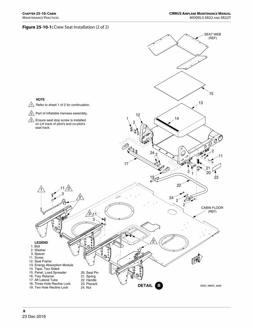
Figure 25-10-1: Crew Seat Installation (1 of 2)
SR22_MM25_4834
Refer to sheet 2 of 2 for continuation.
NOTE
LEGEND 1. Bolt 2. Washer 3. Spacer 4. Upholstery Angle 5. Fairlead Plate 6. Rub Strip 7 . Shoulder Belt Guide 8. Recline Handle 9 . Set Screw10. Head Rest Assembly
10
7
13
124
53
6
98
23 Dec 2016
CHAPTER 25-10: CABIN CIRRUS AIRPLANE MAINTENANCE MANUALMAINTENANCE PRACTICES MODELS SR22 AND SR22T
8
Figure 25-10-1: Crew Seat Installation (2 of 2)
CABIN FLOOR(REF)
113
113
20. Seat Pin21. Spring22. Handle23. Placard24. Nut
Ensure seat stop screw is installed on LH track of pilot's and co-pilot's seat track.
Part of inflatable harness assembly.
NOTE
Refer to sheet 1 of 2 for continuation.
2021
19
11
23
22
21
1
2
2
13
14
15
SEAT WEB(REF)
22
24
17
224
12
12. Seat Frame13. Energy Absorption Module14. Tape, Two Sided15. Panel, Load Spreader16. Tray Retainer17. Aft Lateral Tube18. Three Hole Recline Lock19. Two Hole Recline Lock
LEGEND 1. Bolt 2. Washer 3. Spacer 11. Screw
SR22_MM25_4836
23 Dec 2016

CIRRUS AIRPLANE MAINTENANCE MANUAL CHAPTER 25-10: CABINMODELS SR22 AND SR22T MAINTENANCE PRACTICES
9
(5) Inspection/Check - Crew Seats
(a) Verify security of attach brackets and seat stop screw.
• CAUTION •
If seat is misaligned and cannot be corrected by Adjust-ment/Test - Crew Seat Longitudinal Alignment, contact Cirrus
Design for disposition. (Refer to AMM-Intro-00)
(b) Verify seat forward/aft position adjustment catches both seat pins in all locking positions. To determine if both seat pins are engaged, skew seat forward-and-aft, and note whether second seat pin engages after the first seat pin.1 If seat position adjusts smoothly and seat pins engage simultaneously, seat
track is aligned with seat.2 If seat position is difficult to adjust and/or seat pins require that seat is
skewed before seat pins are aligned with seat track holes, perform Adjust-ment/Test - Crew Seat Longitudinal Alignment. (Refer to 25-10)
(c) Verify seat recline lock functions in all recline positions.
(d) Visually inspect harness webbing for cut or worn edges, damaged stitching, broken fabric threads, tears, excessive chafe marks, excessive wear, and exces-sive fraying.
• NOTE •
A limited amount of “frayed” webbing will retain sufficient strength necessary to meet the strength requirements of the webbing. Frayed webbing is defined as broken fila-ments from either the longitudinal or transverse yarns.
1 Verify that broken or fraying webbing filaments are not numerous enough to obscure the identity of any yarn when viewed from a distance of about 8.0 inches (20.3 cm).
2 Verify amount of fray comprises less than 10% of webbing width and does not exceed 8 inches (20.3 cm) in length.
3 Ensure edge of webbing is free from cuts or tears.4 At non-edge locations, verify number of broken yarns does not exceed 15.5 Ensure number of torn stitches in a stitch pattern does not exceed 15.6 Verify frayed or distorted webbing does not interfere with proper opera-
tion of the restraint system.
(e) Ensure harness is clean and does not contain dirt, oil, grease, or other unwanted particles or substances. If necessary, clean harness. (Refer to 12-20)
(f) Inspect break-over pin alignment.1 Acquire necessary tools, equipment, and supplies.
23 Dec 2016

CHAPTER 25-10: CABIN CIRRUS AIRPLANE MAINTENANCE MANUALMAINTENANCE PRACTICES MODELS SR22 AND SR22T
10
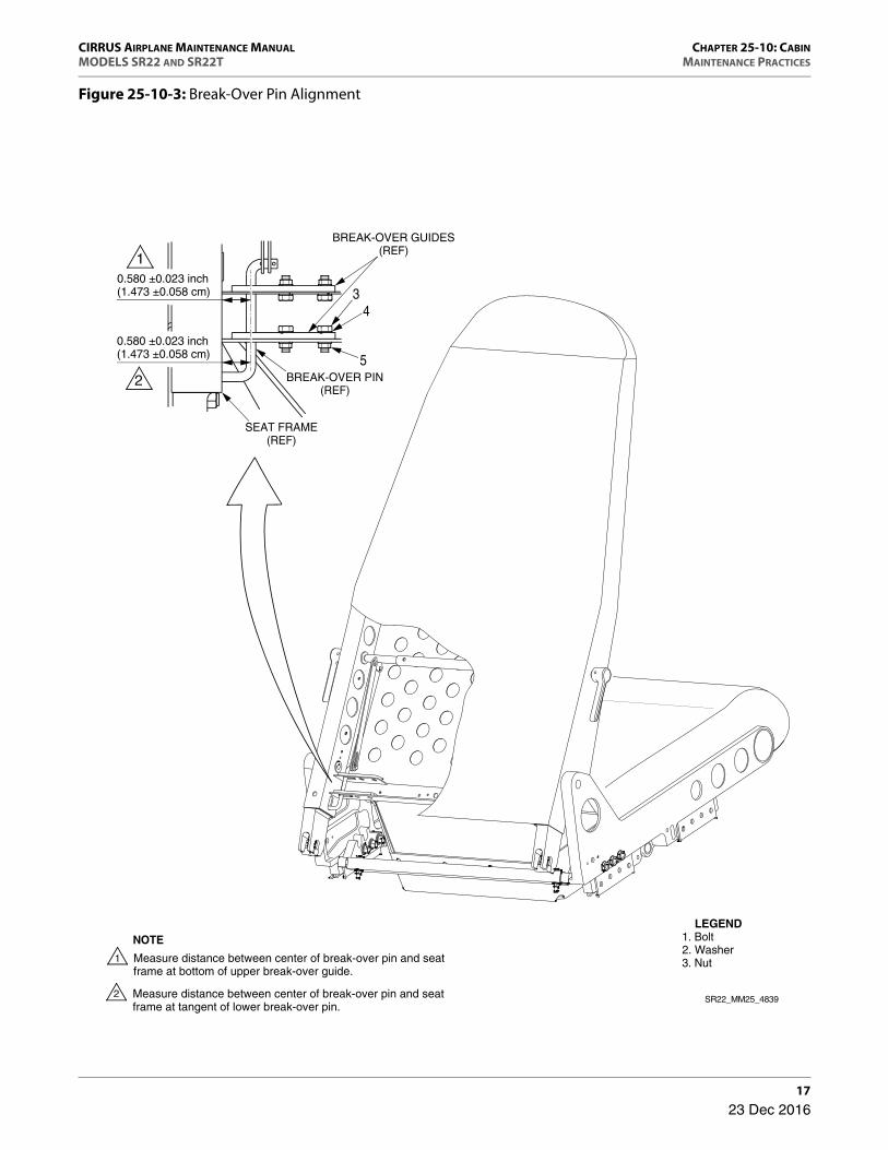
2 Fold crew seats to break-over positions.
3 At lower, aft crew seats, release reclosable fasteners to expose lower seat frame.
4 Using caliper, verify clearance between center of break-over pin and seat back frame at bottom of upper break-over guide is equal to 0.580±0.023 inch (1.473±0.058 cm). (See Figure 25-10-3)
5 Verify clearance between center of break-over pin and seat back frame at tangent of lower break-over pin is equal to 0.580±0.023 inch (1.473±0.058 cm).
6 If measurement is not equal to that specified, perform Adjustment/Test - Break-Over Pin Alignment. (Refer to 25-10)
7 Repeat break-over pin alignment inspection for opposite seat.
(6) Adjustment/Test - Crew Seat Longitudinal Alignment
(See Figure 25-10-2)
(a) Acquire necessary tools, equipment, and supplies.
(b) Remove crew seat. (Refer to 25-10)
(c) Verify seat track longitudinal alignment tool slots are free of debris, pins are secure, sliding pin moves freely forward and aft, and calibration label is identi-fied.
(d) Align seat track longitudinal alignment tool to seat tracks with sliding mecha-nism positioned at the upper RH corner.
(e) Install slots of tool onto seat tracks. Press sliding and stationary pins on tool into corresponding seat track holes.
Description P/N or Spec. Supplier Purpose
Vernier Caliper - Any Source Measure
Description P/N or Spec. Supplier Purpose
Seat Track Longitudinal Alignment Tool 15936-001 Cirrus Design Measure.
Caliper - Any Source Measure.
Lithium Marine Grease 50665-001 Cirrus Design Lubricate.
Permanent Marker - Any Source Mark.
23 Dec 2016

CIRRUS AIRPLANE MAINTENANCE MANUAL CHAPTER 25-10: CABINMODELS SR22 AND SR22T MAINTENANCE PRACTICES
11
• NOTE •
There is about 0.5 inch (1.27 cm) of movement forward to aft when the tool is properly seated on the seat tracks.
(f) Move RH side of tool forward and aft to ensure proper movement of the tool.
• CAUTION •
Using 7.0 to 10.0 lbs (3.2 to 4.5 kg) of force, push tool until binding occurs between the tool and seat tracks. Excessive
force will produce inaccurate measurements.
(g) Push RH side of tool aft to furthermost orientation.
(h) Measure distance between top edge of the tool and top edge of the sliding pin with a caliper. Record measurement as the aft value.
• CAUTION •
Using 7.0 to 10.0 lbs (3.2 to 4.5 kg) of force, push tool until binding occurs between the tool and seat tracks. Excessive
force will produce inaccurate measurements.
(i) Push RH side of tool forward to furthermost orientation.
(j) Measure distance between top edge of the tool and top edge of the sliding pin with a caliper and record measurement as the forward value. Remove tool from seat tracks.
(k) Determine if forward value is within acceptable tolerance.
For example: If aft value is 0.2 inch (0.508 cm) and forward value is -0.245 inch (0.622 cm), use the following formula:
Acceptable Forward Value Range = - (Aft Value)±0.025Acceptable Forward Value Range = - (0.2)±0.025 = -0.2±0.025
(l) If forward value is within acceptable tolerance, offset pins are not required:1 Install crew seat. (Refer to 25-10)
(m) If forward value is not within acceptable tolerance, offset pins are required.1 Determine offset required to correct mismatch.
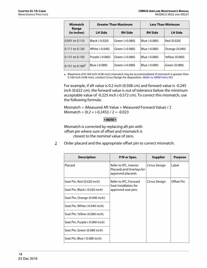
Mismatch Range
(in inches)
Greater Than Maximum Less Than Minimum
LH Side RH Side RH Side LH Side
0.011 to 0.030 - Red (+0.020) Black (-0.020) -
0.031 to 0.050 - Orange (+0.040) White (-0.040) -
0.051 to 0.070 - Yellow (+0.060) Purple (-0.060) -
0.071 to 0.090 - Green (+0.080) Blue (-0.080) -
23 Dec 2016
CHAPTER 25-10: CABIN CIRRUS AIRPLANE MAINTENANCE MANUALMAINTENANCE PRACTICES MODELS SR22 AND SR22T
12
For example, if aft value is 0.2 inch (0.508 cm) and forward value is -0.245 inch (0.622 cm), the forward value is out of tolerance below the minimum acceptable value of -0.225 inch (-0.572 cm). To correct this mismatch, use the following formula:
Mismatch = (Measured Aft Value + Measured Forward Value) / 2Mismatch = (0.2 + (-0.245)) / 2 = -0.023
• NOTE •
Mismatch is corrected by replacing aft pin with offset pin where sum of offset and mismatch is
closest to the nominal value of zero.
2 Order placard and the appropriate offset pin to correct mismatch.
0.091 to 0.110 Black (-0.020) Green (+0.080) Blue (-0.080) Red (0.020)
0.111 to 0.130 White (-0.040) Green (+0.080) Blue (-0.080) Orange (0.040)
0.131 to 0.150 Purple (-0.060) Green (+0.080) Blue (-0.080) Yellow (0.060)
0.151 to 0.160a Blue (-0.080) Green (+0.080) Blue (-0.080) Green (0.080)
a. Maximum of 0.160 inch (4.06 mm) mismatch may be accommodated, If mismatch is greater than 0.160 inch (4.06 mm), contact Cirrus Design for disposition. (Refer to AMM-Intro-00)
Description P/N or Spec. Supplier Purpose
Placard Refer to IPC, Interior Placards and Overlays for approved placards
Cirrus Design Label
Seat Pin, Red (0.020 inch) Refer to IPC, Forward Seat Installation for approved seat pins
Cirrus Design Offset Pin
Seat Pin, Black (-0.020 inch)
Seat Pin, Orange (0.040 inch)
Seat Pin, White (-0.040 inch)
Seat Pin, Yellow (0.060 inch)
Seat Pin, Purple (-0.060 inch)
Seat Pin, Green (0.080 inch)
Seat Pin, Blue (-0.080 inch)
Mismatch Range
(in inches)
Greater Than Maximum Less Than Minimum
LH Side RH Side RH Side LH Side
23 Dec 2016

CIRRUS AIRPLANE MAINTENANCE MANUAL CHAPTER 25-10: CABINMODELS SR22 AND SR22T MAINTENANCE PRACTICES
13
For example, if mismatch is -0.023 inch (-0.058 cm), use pin required to offset as close to zero as possible.
Offset = - (Mismatch)Offset = - (-0.023) = 0.023
A pin with offset of 0.020 inch (Red) will bring longitudinal mismatch within tolerance.
• NOTE •
It may be necessary to use opposite displace-ment seat pins on each side of seat to compen-
sate for misalignment.
For example, if mismatch is -0.091 inch (-0.231 cm), use combination of pins required to offset as close to zero as possible.
Offset = - (Mismatch)Offset = - (-0.091) = 0.091
A pin with offset of 0.080 inch (Green) installed at RH side and a pin with offset of 0.020 inch (Black) installed at LH side will bring longitudinal mismatch within tolerance.
3 Disassemble crew seat adjustment handle. (Refer to 25-10)
• NOTE •
Mismatch measured using the Seat Track Longitudinal Alignment Tool is only nominal
track alignment. Other factors such as seat shape may also influence pin engagement
function. Any selection of offset pins may be used such that best engagement function is
achieved.
4 Replace the existing pin(s) with the offset pin(s). Discard the existing pin(s).5 Assemble crew seat adjustment handle. (Refer to 25-10)6 Lubricate seat pins with lithium marine grease.7 Verify screws are loose enough to permit smooth, unrestricted forward and
aft travel of seat.
23 Dec 2016
CHAPTER 25-10: CABIN CIRRUS AIRPLANE MAINTENANCE MANUALMAINTENANCE PRACTICES MODELS SR22 AND SR22T
14
• CAUTION •
Once seat is modified using offset seat pins, it may only be installed in seat location affected by longi-
tudinal mismatch.
8 Install crew seat. (Refer to 25-10)9 Verify seat forward and aft position adjusts to all locking positions with
relative ease.10 Using marker on placard, indicate pins utilized, location of each pin, and
seat location (pilot or co-pilot).11 Attach placard to visible location on lower seat frame.
23 Dec 2016

CIRRUS AIRPLANE MAINTENANCE MANUAL CHAPTER 25-10: CABINMODELS SR22 AND SR22T MAINTENANCE PRACTICES
15
Figure 25-10-2: Seat Track Longitudinal Adjustment
Using 7.0 to 10.0 lbs (3.2 to 4.5 kg) of force, push tool until binding occurs between the tool and seat tracks. Excessive force will produce inaccurate measurements.
SLIDE PLATE(REF)
FRONT VIEW
BACK VIEW
SLOTS (REF)
SLIDING PINS(REF)
STATIONARY PINS(REF)
1
CALIBRATIONLABEL (REF)
SEAT TRACK(REF)
SEAT TRACK(REF)
1
LEGEND 1. Seat Track Longitudinal Alignment Tool
Install slots of tool onto the seat tracks. Press sliding and stationary pins into corresponding seat track holes.
NOTE
Verify seat track longitudinal alignment tool slots are free of debris, pins are secure, sliding pin moves freely forward and aft, and calibration label is identified.
1
AFT (POSITIVE) VALUE POSITION FORWARD (NEGATIVE) VALUE POSITION
SR22_MM25_4446
SLIDE PLATE(REF)
Example:+ 0.2 inch(0.508 cm)
Example:- 0.245 inch(0.622 cm)
23 Dec 2016

CHAPTER 25-10: CABIN CIRRUS AIRPLANE MAINTENANCE MANUALMAINTENANCE PRACTICES MODELS SR22 AND SR22T
16
(7) Adjustment/Test - Break-Over Pin Alignment
(See Figure 25-10-3)
(a) Acquire necessary tools, equipment, and supplies.
(b) Free break-over pin by slightly loosening four sets of attaching hardware securing break-over guides to seat frame.
(c) Press break-over pin and guides inboard or outboard as required until break-over pin is positioned within tolerance.
(d) Using a caliper, verify clearance between center of break-over pin and seat back frame at bottom of upper break-over guide is equal to 0.580±0.023 inch (1.473±0.058 cm).
(e) Verify clearance between center of break-over pin and seat back frame at tangent of lower break-over pin is equal to 0.580±0.023 inch (1.473±0.058 cm).
(f) Tighten four sets of attaching hardware securing break-over guides to seat frame.
(8) Cleaning - Crew Seats
Periodically vacuum and clean crew seats with approved cleaning solutions to ensure surface dirt and dust removal. (Refer to 12-20)
Description P/N or Spec. Supplier Purpose
Caliper - Any Source Measure.
23 Dec 2016
CIRRUS AIRPLANE MAINTENANCE MANUAL CHAPTER 25-10: CABINMODELS SR22 AND SR22T MAINTENANCE PRACTICES
17
Figure 25-10-3: Break-Over Pin Alignment
SR22_MM25_4839
LEGEND 1. Bolt 2. Washer 3. Nut
BREAK-OVER PIN(REF)
BREAK-OVER GUIDES(REF)
SEAT FRAME(REF)
0.580 ±0.023 inch(1.473 ±0.058 cm) 3
5
4
0.580 ±0.023 inch(1.473 ±0.058 cm)
Measure distance between center of break-over pin and seat frame at bottom of upper break-over guide.
NOTE
Measure distance between center of break-over pin and seat frame at tangent of lower break-over pin.
23 Dec 2016

CHAPTER 25-10: CABIN CIRRUS AIRPLANE MAINTENANCE MANUALMAINTENANCE PRACTICES MODELS SR22 AND SR22T
18
B. Crew Seat Harness
(See Figure 25-10-4)
(1) Removal - Crew Seat Harness
(a) Remove crew seat. (Refer to 25-10)
(b) Disassemble crew seat back top. (Refer to 25-10)
(c) Disconnect harness inflator hose from inflator assembly.
(d) Remove bolts and washers securing dual inertia reel to crossover bar on back of crew seat.
(2) Disassembly - Crew Seat Harness Lap Belt Attach Clip
(a) Disassemble crew seat recline handle. (Refer to 25-10)
• CAUTION •
Use care to avoid damaging upholstery on recline handle shafts.
(b) At lower, aft crew seat back, release reclosable fasteners and slide upholstery upward to expose seat back frame.
(c) Remove bolt, washer, spacer, and anti-rotation tab securing lap belt attach clip to side of lower crew seat frame. Repeat on opposite side of crew seat.
(3) Assembly - Crew Seat Harness Lap Belt Attach Clip
(a) At forward lap belt installation hole, secure lap belt attach clip to lower seat assembly with anti-rotation tab, spacer, washer, and bolt. Torque bolt 55 in-lb (6.2 Nm). Verify lap belt attach clip rotates freely from stop to stop. Repeat on opposite side of crew seat. (Refer to 20-60)
(b) Place seat back upholstery into position and press firmly on reclosable fasteners to secure upholstery to seat back.
(c) Assemble crew seat recline handle. (Refer to 25-10)
23 Dec 2016
CIRRUS AIRPLANE MAINTENANCE MANUAL CHAPTER 25-10: CABINMODELS SR22 AND SR22T MAINTENANCE PRACTICES
19
(4) Installation - Crew Seat Harness
(a) Position dual inertia reel to crossover bar with reels positioned upward and secure to seat back with bolts and washers.
(b) Connect inflator hose to inflator assembly.1 Acquire necessary tools, equipment, and supplies.
2 Route inflator hose from seat belt assembly between seat belt webbing and seat back web, ensuring twists and bends are minimized.
3 Apply threadlocker to threads of harness inflator hose fitting.4 Connect harness inflator hose to inflator assembly. Torque hose fitting 110
to 130 in-lb (12.4 to 14.7 Nm). (Refer to 20-60)
(c) Assemble crew seat back top. (Refer to 25-10)
(d) Install crew seat. (Refer to 25-10)
(e) Perform Adjustment/Test - Crew Seat Harness. (Refer to 25-10)
(5) Inspection/Check - Crew Seat Harness
(a) Remove LH crew seat. (Refer to 25-10)
(b) Remove cabin floor access panel CF2L. (Refer to 6-00)
(c) Verify security of electronic module assembly mounting hardware.
(d) Verify security of connection between electronic module assembly and cable interface assembly.
(e) Disassemble crew seat recline handle. (Refer to 25-10)
• CAUTION •
Use care to avoid damaging upholstery on recline handle shafts.
(f) At lower, aft crew seat back, release reclosable fasteners and slide upholstery upward to expose seat back frame.
(g) Verify security of inflator assembly mounting hardware.
(h) Verify security of connection between harness inflator hose and inflator assembly. Torque hose fitting 110 to 130 in-lb (12.4 to 14.7 Nm). (Refer to 20-60)
Description P/N or Spec. Supplier Purpose
Threadlocker Loctite® 242 Any Source Lock threads.
23 Dec 2016
CHAPTER 25-10: CABIN CIRRUS AIRPLANE MAINTENANCE MANUALMAINTENANCE PRACTICES MODELS SR22 AND SR22T
20
(i) Verify security of connection between inflator cable assembly and inflator assembly.
(j) Visually inspect exposed hoses and cables for tears, fraying, and excessive wear.
(k) Install cabin floor access panel CF2L. (Refer to 6-00)
(l) Place seat back upholstery into position and press firmly on reclosable fasteners to secure upholstery to seat back.
(m) Position recline handle onto shaft so that handle is pointing in a downward direction and secure with set screws. Repeat for opposite side of seat.
(n) Assemble crew seat recline handle. (Refer to 25-10)
(o) Install LH crew seat. (Refer to 25-10)
(p) Perform Adjustment/Test - Crew Seat Harness. (Refer to 25-10)
(6) Adjustment/Test - Crew Seat Harness
The system diagnostic tool (SDT) is a electronic, hand-held testing device used to verify inflatable restraint system functionality and facilitate component trouble-shooting. The SDT connects directly to the diagnostic connector on the inflatable restraint cable interface assembly. LEDs for battery, sensor, and inflator indicate green for pass and red for fail. A three-position switch enables testing of multiple seats.
• WARNING •
Electronic module assembly must be securely installed in airplane prior to testing or inadvertent system deployment may occur.
(a) Acquire necessary tools, equipment, and supplies.
(b) Set SDT power switch to ON position.
(c) Verify SDT battery indicator illuminates green. If SDT battery indicator illumi-nates red, replace SDT battery.
(d) Set SDT toggle switch to number of seats connected to electronic module assembly.
(e) Remove right mid console trim. (Refer to 25-10)
(f) Disconnect diagnostic connector from center console by sliding plug off rail from connector plug.
Description P/N or Spec. Supplier Purpose
System Diagnostic Tool 508987-401 AmSafe Aviation Test inflatable restraint system.
23 Dec 2016

CIRRUS AIRPLANE MAINTENANCE MANUAL CHAPTER 25-10: CABINMODELS SR22 AND SR22T MAINTENANCE PRACTICES
21
• CAUTION •
Disconnect SDT from diagnostic connector once test is completed. If SDT remains connected to diagnostic connector
for an extended period of time, power is drained from elec-tronic module assembly.
(g) Connect SDT connector to diagnostic connector on interface cable.
(h) Verify LEDs on SDT indicate green.
(i) If one or more of the LEDs indicate red, perform the following steps:1 Check all cable assembly connectors and retest.2 If battery and/or sensor LED indicates red, replace the electronic module
assembly and retest. (Refer to 25-10)3 If inflator LED indicates red, replace the inflator cable assembly and retest.
(Refer to 25-10)4 If inflator LED still indicates red, replace the inflator assembly and retest.
(Refer to 25-10)5 If any fail condition exists after replacing electronic module assembly,
inflator cable, and inflator assembly, replace the interface cable and retest. (Refer to 25-10)
(j) Set SDT power switch to OFF position.
(k) Disconnect SDT connector from diagnostic connector on interface cable.
(l) Install diagnostic connector to RH center console flange by sliding plug forward onto rail until connector locks into place with connector plug.
(m) Install right mid console trim. (Refer to 25-10)
C. Inflatable Restraint System, Inflator Assembly
(See Figure 25-10-4)
The inflator assembly is a stored, gas/energetic material device. Severe personal injury or bodily harm may be caused by misuse and/or tampering. Do not tamper with or mishandle the product in any way. Never attempt to open the inflator to service the inflator system. Never apply electrical current to the electronics connection.
(1) Removal - Inflator Assembly
(a) Remove crew seat. (Refer to 25-10)
(b) Disassemble crew seat recline handle. (Refer to 25-10)
23 Dec 2016

CHAPTER 25-10: CABIN CIRRUS AIRPLANE MAINTENANCE MANUALMAINTENANCE PRACTICES MODELS SR22 AND SR22T
22
• CAUTION •
Use care to avoid damaging upholstery on recline handle shafts.
(c) At lower, aft crew seat back, release reclosable fasteners and slide upholstery upward to expose seat back frame.
(d) Disconnect inflator cable assembly from inflator assembly.
(e) Disconnect harness inflator hose from inflator assembly.
(f) Loosen bolts, washers, spacers, and nuts securing inflator assembly clamps.
(g) Remove inflator assembly from seat back.
(2) Installation - Inflator Assembly
(a) Acquire necessary tools, equipment, and supplies.
(b) Position inflator assembly into clamps and secure to seat with bolts, washers, spacers, and nuts.
(c) Apply threadlocker to threads of harness inflator hose fitting.
(d) Connect harness inflator hose to inflator assembly. Torque hose fitting 110 to 130 in-lb (12.4 to 14.7 Nm). (Refer to 20-60)
(e) Connect inflator cable assembly to inflator assembly.
(f) Place seat back upholstery into position and press firmly on reclosable fasteners to secure upholstery to seat back.
(g) Assemble crew seat recline handle. (Refer to 25-10)
(h) Install crew seat. (Refer to 25-10)
(i) Perform Adjustment/Test - Crew Seat Harness. (Refer to 25-10)
D. Inflatable Restraint System, Electronic Module Assembly
(See Figure 25-10-4)
• WARNING •
Avoid magnetic fields near the electronic module assembly as inadvertent system deployment may occur.
Description P/N or Spec. Supplier Purpose
Threadlocker Loctite® 242 Any Source Lock threads.
23 Dec 2016

CIRRUS AIRPLANE MAINTENANCE MANUAL CHAPTER 25-10: CABINMODELS SR22 AND SR22T MAINTENANCE PRACTICES
23
Secure electronic module assembly to fuselage floor before connecting wire harness. An unsecured, electrically connected electronic module assembly
may result in inadvertent system deployment.
Do not drop the electronic module assembly as damage to the electronics, battery, or sensor may occur.
(1) Removal - Electronic Module Assembly
(a) Remove LH crew seat. (Refer to 25-10)
(b) Remove cabin floor access panel CF2L. (Refer to 6-00)
(c) Disconnect cable interface assembly from electronic module assembly.
(d) Remove screws and nut plates securing electronic module assembly to fuselage floor.
(e) Remove electronic module assembly from airplane.
(2) Installation - Electronic Module Assembly
(a) Position electronic module assembly to fuselage floor with directional arrow facing forward and secure with screws and nut plates.
(b) Torque screws 6.0±2.0 in-lb (0.68±0.23 Nm). Torque stripe not required. (Refer to 20-60)
(c) Connect interface cable to electronic module assembly.
(d) Install cabin floor access panel CF2L. (Refer to 6-00)
(e) Install LH crew seat. (Refer to 25-10)
(f) Perform Adjustment/Test - Crew Seat Harness. (Refer to 25-10)
E. Inflatable Restraint System, Interface Cable
(See Figure 25-10-4)
(1) Removal - Interface Cable
(a) Remove crew seats. (Refer to 25-10)
(b) Remove cabin floor access panels CF1R, CF1L, and CF2L. (Refer to 6-00)
(c) Remove right mid console trim. (Refer to 25-10)
23 Dec 2016

CHAPTER 25-10: CABIN CIRRUS AIRPLANE MAINTENANCE MANUALMAINTENANCE PRACTICES MODELS SR22 AND SR22T
24
(d) At RH center console flange, disconnect diagnostic connector assembly from center console by sliding connector assembly forward and off mounting rail.
(e) Remove screw, washer, and clamp securing interface cable to bracket mounted on seat attach bracket. Repeat for opposite side of airplane.
(f) Remove cable ties securing interface cable to cable tiedowns on spar tunnel.
(g) Disconnect interface cable from electronic module assembly.
(h) Route interface cables.1 At LH aft corner of fuselage floor, route LH branch of interface cable from
electronic module assembly aft along floor, and down through fuselage floor. Route interface cable along forward surface of spar tunnel, LH forward longeron, and up through LH pass-through hole.
2 At RH aft corner of fuselage floor, route RH branch of interface cable down through fuselage floor, along forward surface of spar tunnel, RH forward longeron, and up through RH pass-through hole.
(i) At center console, locate diagnostic connector assembly of interface cable extending from two pass-through holes in fuselage floor just aft of the forward pulley gang. Retrieve remaining interface cable from pass-through holes and remove interface cable from airplane.
(2) Disassembly - Interface Cable
To disassemble diagnostic connector mounting rail, perform the following steps:
(a) Remove right mid console trim. (Refer to 25-10)
(b) At RH center console flange, disconnect diagnostic connector assembly from center console by sliding connector assembly forward and off mounting rail.
(c) Remove screws securing mounting rail to RH center console flange.
(3) Assembly - Interface Cable
To assemble diagnostic connector mounting rail, perform the following steps:
(a) Install screws securing mounting rail to RH center console flange.
(b) Install connector assembly to RH center console flange by sliding plug aft on mounting rail until connector assembly locks into place.
(c) Install right mid console trim. (Refer to 25-10)
23 Dec 2016

CIRRUS AIRPLANE MAINTENANCE MANUAL CHAPTER 25-10: CABINMODELS SR22 AND SR22T MAINTENANCE PRACTICES
25
(4) Installation - Interface Cable
(a) Acquire necessary tools, equipment, and supplies.
(b) At center console, locate pass-through holes in fuselage floor aft of forward pulley gang.
(c) Route interface cables.1 Route RH branch of interface cable through RH pass-through hole, RH
forward longeron, along forward surface of spar tunnel, and up through RH aft corner of fuselage floor.
2 Route LH branch of interface cable through LH pass-through hole, LH forward longeron, and along forward surface of spar tunnel. At LH aft corner of fuselage floor, route LH branch of wire harness up through fuse-lage floor, and electronic module assembly branch of wire harness forward along floor.
(d) Connect interface cable to electronic module assembly.
(e) Position interface cable to cable tiedowns on spar tunnel and secure with cable ties.
(f) Position interface cable to bracket mounted on seat attach bracket and secure with screw, washer, and clamp. Repeat for opposite side of airplane.
(g) Install connector assembly to RH center console flange by sliding plug aft on mounting rail until connector assembly locks into place.
(h) Install right mid console trim. (Refer to 25-10)
(i) Install cabin floor access panels CF1R, CF1L, and CF2L. (Refer to 6-00)
(j) Install crew seats. (Refer to 25-10)
(k) Perform Adjustment/Test - Crew Seat Harness. (Refer to 25-10)
F. Inflatable Restraint System, Inflator Cable
(See Figure 25-10-4)
(1) Removal - Inflator Cable
(a) Disassemble crew seat recline handle. (Refer to 25-10)
Description P/N or Spec. Supplier Purpose
Cable Ties - Any Source Secure cable.
23 Dec 2016

CHAPTER 25-10: CABIN CIRRUS AIRPLANE MAINTENANCE MANUALMAINTENANCE PRACTICES MODELS SR22 AND SR22T
26
• CAUTION •
Use care to avoid damaging upholstery on recline handle shafts.
(b) At lower, aft crew seat back, release reclosable fasteners and slide upholstery upward to expose seat back frame.
(c) Remove cable ties securing inflator cable to cable tiedowns on spar tunnel.
(d) Disconnect inflator cable from inflator assembly.
(e) Disconnect inflator cable from interface cable. Remove inflator cable from airplane.
(2) Installation - Inflator Cable
(a) Acquire necessary tools, equipment, and supplies.
(b) Connect inflator cable to interface cable.
(c) Connect inflator cable to inflator assembly.
(d) Position inflator cable to cable tiedowns on seat back and secure with cable ties.
(e) Place seat back upholstery into position and press firmly on reclosable fasteners to secure upholstery to seat back.
(f) Assemble crew seat recline handle. (Refer to 25-10)
(g) Perform Adjustment/Test - Crew Seat Harness. (Refer to 25-10)
Description P/N or Spec. Supplier Purpose
Cable Ties - Any Source Secure cable.
23 Dec 2016
CIRRUS AIRPLANE MAINTENANCE MANUAL CHAPTER 25-10: CABINMODELS SR22 AND SR22T MAINTENANCE PRACTICES
27
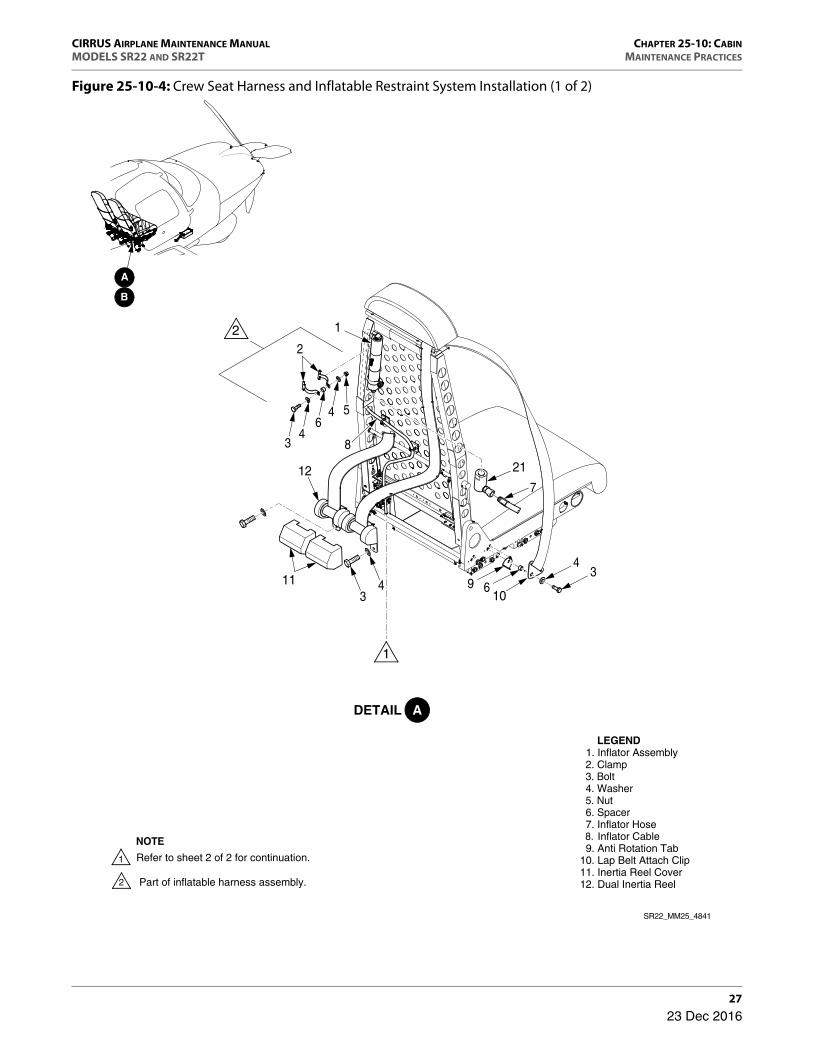
Figure 25-10-4: Crew Seat Harness and Inflatable Restraint System Installation (1 of 2)
9 610
43
2
4
43
7
1
8
56
2112
43
11
SR22_MM25_4841
LEGEND 1. Inflator Assembly 2. Clamp 3. Bolt 4. Washer 5. Nut 6. Spacer 7. Inflator Hose 8. Inflator Cable 9. Anti Rotation Tab10. Lap Belt Attach Clip11. Inertia Reel Cover12. Dual Inertia Reel Part of inflatable harness assembly.
NOTE
Refer to sheet 2 of 2 for continuation.
23 Dec 2016

CHAPTER 25-10: CABIN CIRRUS AIRPLANE MAINTENANCE MANUALMAINTENANCE PRACTICES MODELS SR22 AND SR22T
28
Figure 25-10-4: Crew Seat Harness and Inflatable Restraint System Installation (2 of 2)
1317
1819
17
SR22_MM25_4843
LEGEND 2. Clamp 3. Bolt 4. Washer 5. Nut 8. Inflator Cable13. Connector Plug14. Bracket15. Electronic Module Assembly16. Plate Assembly17. Interface Cable18. Screw19. Mounting Rail
3
15
16
3
142
43
4
5
8
17
WIREHARNESS
(REF)
RH CENTERCONSOLE FLANGE
(REF)
CABIN FLOOR(REF)
NOTE
Refer to sheet 1 of 2 for continuation.
Installed on RH side of cabin floor.
23 Dec 2016

CIRRUS AIRPLANE MAINTENANCE MANUAL CHAPTER 25-10: CABINMODELS SR22 AND SR22T MAINTENANCE PRACTICES
29
G. Passenger Seats
(See Figure 25-10-5)
• CAUTION •
Avoid kneeling or stepping on seats so as to not crush energy absorption modules.
Remove seat base assembly secured with reclosable fasteners carefully so as to not damage fasteners.
(1) Removal - Passenger Seat Base
(a) Remove cotter pins used to secure the seat base assembly to floor.
(b) Lift forward edge of seat base assembly up, pull seat base assembly forward to release reclosable fasteners, and remove seat base assembly.
(2) Installation - Passenger Seat Base
(a) Install seat base assembly on aft floor and press rear seat base assembly firmly onto reclosable fasteners.
• NOTE •
If seat base wobbles, one to three washers may be installed at each pin below the seat or cotter pin to elimi-
nate excess pin engagement.
(b) Secure forward seat brackets with new cotter pins.
(3) Removal - Passenger Seat Back
(a) At outboard seat, slip harness strap free of seat belt guide and stow harness aft of seat.
(b) Serials w/ three-harness installation: If removing LH seat, disengage LH center harness latch securing seat harness to LH center harness mount. Unbuckle seat harness, and route harness aft through seat pass-through hole.
(c) With no pressure on seat back, rotate lever to recline position and fold seat back forward.
(d) Remove bolts, washers, clock spring, housing, and nuts securing seat back to floor brackets, and remove seat back assembly.
23 Dec 2016

CHAPTER 25-10: CABIN CIRRUS AIRPLANE MAINTENANCE MANUALMAINTENANCE PRACTICES MODELS SR22 AND SR22T
30
(4) Disassembly - Passenger Seat Back
(a) Recline handle1 At outboard seat, loosen set screws securing crew seat recline handle to
shaft, and slide handle off shaft.
(b) Seat belt guide1 At aft seat, remove screws securing seat belt guide to seat.
(c) Baggage strap anchor plates1 At aft seat, remove screws securing anchor plates to seat.
(d) Actuator assembly1 At outboard seat, loosen jam nut at base of recline pin housing.2 Depress pin shoulder flush with recline pin housing while loosening barrel
nut until pin slot can be detached from cable ball.3 Remove spring from recline pin housing.4 Remove recline handle. (Refer to 25-10)5 Remove retaining ring securing actuator shaft to seat.6 Slide actuator shaft inboard at flanged bushing and disengage from cable
S-hook.7 Remove flanged bushing from seat.8 Remove screws and washers securing recline pin housing to seat. 9 Release cable clip and remove cable from pass-through hole.10 Remove grommet from pass-through hole.
(e) Seat hinge plates1 At inboard/outboard seat, remove screws, washers, and nuts securing seat
hinge plates to seat.
(5) Assembly - Passenger Seat Back
(a) Recline handle1 Position recline handle onto shaft so that handle is pointing in a downward
direction, slide reclining handle on shaft, then tighten set screws securing crew seat reclining handle to shaft.
(b) Seat belt guide1 At aft seat, position seat belt guide to aft seat and install screws securing
seat belt guide to seat.
(c) Baggage strap anchor plates1 At aft seat, install screws securing anchor plates to seat.
23 Dec 2016
CIRRUS AIRPLANE MAINTENANCE MANUAL CHAPTER 25-10: CABINMODELS SR22 AND SR22T MAINTENANCE PRACTICES
31
(d) Actuator assembly1 At outboard seat, install grommet at pass-through hole.2 Route cable in pass-through hole and secure to cable clip.3 Install screws and washers securing recline pin housing to seat. 4 Install flanged bushing into seat.5 Engage actuator shaft onto cable S-hook and slide actuator shaft outboard
through seat at flanged bushing.6 Install retaining ring securing actuator shaft to seat.7 Install recline handle. (Refer to 25-10)8 Install spring into recline pin housing.9 Route cable through recline pin housing and position cable ball in pin slot. 10 Depress pin shoulder flush with recline pin housing while tightening barrel
nut until spring compression is maintained by pin tension.11 Tighten jam nut at base of recline pin housing.
(e) Seat hinge plates1 At inboard/outboard seat, install screws, washers, and nuts securing seat
hinge plates to seat.
(6) Installation - Passenger Seat Back
(a) Position clock spring to outboard floor bracket so that outer clock spring tab is facing aft, and inner clock spring tab is captured by slot in outboard floor bracket.
(b) Position seat back to floor brackets so that lower edge of aft outboard seat flange contacts outer clock spring tab. Secure seat to floor brackets with bolts, washers, clock spring, housing, and nuts.
(c) Fold passenger seat to upright position.
• CAUTION •
When routing seat belt straps, ensure belts do not become twisted.
(d) At outboard seat, slip outboard harness into seat belt guide and route harness forward.
(e) Serials w/ three-harness installation: If installing LH seat, route center harness forward through seat pass-through hole and engage LH center harness latch to LH center harness mount. Buckle seat harness.
(f) If actuator assembly was removed, perform Adjustment/Test - Passenger Seat Back Recline Pin Engagement. (Refer to 25-10)
23 Dec 2016

CHAPTER 25-10: CABIN CIRRUS AIRPLANE MAINTENANCE MANUALMAINTENANCE PRACTICES MODELS SR22 AND SR22T
32
(7) Adjustment/Test - Passenger Seat Back Recline Pin Engagement
(See Figure 25-10-5)
(a) Acquire necessary tools, equipment, and supplies.
(b) Loosen jam nut at base of recline pin housing.
(c) Tighten or loosen barrel nut as required to adjust pin spring compression.
(d) Using caliper, verify measurement between flat surfaces of housing and pin shoulder is approximately 0.10 inch (2.54 mm).
(e) Once measurement is obtained, hold recline handle while slowly loosening barrel nut. Stop loosening barrel nut when reduction in tension can be felt in recline handle.
(f) Tighten jam nut at base of recline pin housing.
(g) Rotate lever and fold passenger seat to available recline positions.
(h) Verify pin engages lock hole when recline handle is not actuated.
(i) Verify pin fully dis-engages lock hole when recline handle is actuated.
(j) Repeat pin spring compression adjustment as necessary.
(8) Cleaning - Passenger Seats
(Refer to 12-20)
Description P/N or Spec. Supplier Purpose
Vernier Caliper - Any Source Measure
23 Dec 2016

CIRRUS AIRPLANE MAINTENANCE MANUAL CHAPTER 25-10: CABINMODELS SR22 AND SR22T MAINTENANCE PRACTICES
33
Figure 25-10-5: Passenger Seat Installation (1 of 3)
5
SR22_MM25_4448
LEGEND 1. Screw 2. Washer 3 . Nut 4 . Pin 5 . Cotter Pin 6 . Spring 7 . Cover 8 . Bolt
24
2
3
32
6
2 7
2
2
22
23
8
8
B
NOTEInstall up to three washers per pin as required.
C
23 Dec 2016
CHAPTER 25-10: CABIN CIRRUS AIRPLANE MAINTENANCE MANUALMAINTENANCE PRACTICES MODELS SR22 AND SR22T
34
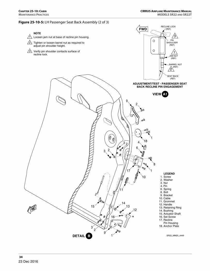
Figure 25-10-5: LH Passenger Seat Back Assembly (2 of 3)
BARREL NUT(REF)
ADJUSTMENT/TEST - PASSENGER SEATBACK RECLINE PIN ENGAGEMENT
JAM NUT(REF)
PINSHOULDER
(REF)
RECLINE LOCK(REF)
SEAT BACK(REF)
NOTELoosen jam nut at base of recline pin housing.
Tighten or loosen barrel nut as required toadjust pin shoulder height.
Verify pin shoulder contacts surface ofrecline lock.
10
4
63 2
23 181
17
8
1
92
1514
1312
91
16
32
11
SR22_MM25_4449
LEGEND 1. Screw 2. Washer 3. Nut 4. Pin 6. Spring 8. Bolt 9. Bracket10. Cable11. Grommet12. Handle13. Retaining Ring14. Bushing15. Actuator Shaft16. Set Screw 17. Recline Pin Housing18. Anchor Plate
23 Dec 2016

CIRRUS AIRPLANE MAINTENANCE MANUAL CHAPTER 25-10: CABINMODELS SR22 AND SR22T MAINTENANCE PRACTICES
35
Figure 25-10-5: RH Passenger Seat Back Assembly (3 of 3)
CDETAIL
29
118 4
68 9
8 9
8
1
10
17
11
1213
14
16
15
32
19
LEGEND 1. Screw 2. Washer 3. Nut 4. Pin 6. Spring 8. Bolt 9. Bracket10. Cable11. Grommet12. Handle13. Retaining Ring14. Bushing15. Actuator Shaft16. Set Screw 17. Recline Pin Housing18. Anchor Plate
SR22_MM25_4909
23 Dec 2016
CHAPTER 25-10: CABIN CIRRUS AIRPLANE MAINTENANCE MANUALMAINTENANCE PRACTICES MODELS SR22 AND SR22T
36
H. Passenger Seat Harness
(See Figure 25-10-6)
(1) Removal - Passenger Seat Harness
(a) Remove aft bulkhead trim panel and rear headliner. (Refer to 25-10)
(b) LH or RH Harness1 Remove bolt, washers, bushing, and nut securing seat harness to lower
outboard harness mount.2 Remove bolt, washers, bushing, and nut securing seat harness to lower
inboard harness mount.3 At outboard seat, slip outboard harness strap free of seat belt guide.4 Remove bolts, washers, and nuts securing inertia reel to upper outboard
seat harness mount. Remove harness from airplane.
(c) Serials w/ three-harness installation: Center Harness1 Disengage LH center latch securing seat harness to LH center harness
mount.2 Disengage RH center latch securing seat harness to RH center harness
mount, and route harness aft through seat pass-through hole.3 Remove bolts, washers, and nuts securing inertia reel to upper center seat
harness mount. Remove harness from airplane.
(2) Installation - Passenger Seat Harness
Inertia reel must be installed with harness coming off the top side of inertia reel. The inertia reel plate must be installed on the underside of mount.
(a) LH or RH Harness1 Install inertia reel plate on underside of upper outboard seat harness
mount and secure with bolts, washers, and nuts.
2 At outboard seat, slip outboard harness strap into seat belt guide.3 Install bolt, washers, bushing, and nut securing seat harness to lower
inboard harness mount.4 Install bolt, washers, bushing, and nut securing seat harness to lower
outboard harness mount.
23 Dec 2016

CIRRUS AIRPLANE MAINTENANCE MANUAL CHAPTER 25-10: CABINMODELS SR22 AND SR22T MAINTENANCE PRACTICES
37
(b) Serials w/ three-harness installation: Center Harness1 Install inertia reel plate on underside of upper center seat harness mount
and secure with bolts, washers, and nuts.2 Route center harness forward through seat pass-through hole.3 Engage LH center latch securing seat harness to LH center harness mount.
4 Engage RH center latch securing seat harness to RH center harness mount.
(c) Secure aft bulkhead trim panel. (Refer to 25-10)
(d) Perform Inspection/Check - Passenger Seat Harness. (Refer to 25-10)
(3) Inspection/Check - Passenger Seat Harness
(a) Examine harness webbing for cut or worn edges, damaged stitching, broken fabric threads, tears, excessive chafe marks, excessive wear, excessive fusing.
• NOTE •
A limited amount of “frayed” webbing will retain sufficient strength necessary to meet the strength requirements of the webbing. Frayed webbing is defined as broken fila-ments from either the longitudinal or transverse yarns.
(b) Verify that broken or fraying webbing filaments are not numerous enough to obscure the identity of any yarn when viewed from a distance of about 8.0 inches (20.3 cm).
23 Dec 2016

CHAPTER 25-10: CABIN CIRRUS AIRPLANE MAINTENANCE MANUALMAINTENANCE PRACTICES MODELS SR22 AND SR22T
38
Figure 25-10-6: Passenger Seat Harness
SR22_MM25_4451
LEGEND1. Bolt2. Seat Belt Assembly3. Washer4. Nut5. Bushing6. FittingNOTE
Strap must go over inertia reel.
1
1 1
1
1
2
34
2
2
2
33
3
3
3
3
4
4
4
5
5
5
6
A
ADETAIL
23 Dec 2016

CIRRUS AIRPLANE MAINTENANCE MANUAL CHAPTER 25-10: CABINMODELS SR22 AND SR22T MAINTENANCE PRACTICES
39
I. Cargo Net
(See Figure 25-10-7)
(1) Removal - Cargo Net
(a) At passenger seat backs, depress and hold latch pins to disengage latches securing cargo net straps to anchor plates.
(b) Slide latches off anchor plates.
(c) Remove bolts, washers, and nuts securing inertia reels to cargo net mounts. Remove cargo net from airplane.
(2) Installation - Cargo Net
Inertia reel must be installed with harness coming off the bottom side of inertia reel. The inertia reel plate must be installed on the upperside of mount.
(a) Install inertia reel plate on upperside of cargo net mounts and secure with bolts, washers, and nuts.
(b) Position cargo net straps to passenger seat backs and engage latches to anchor plates.
(c) Perform Inspection/Check - Cargo Net. (Refer to 25-10)
(3) Inspection/Check - Cargo Net
(a) Examine harness webbing for cut or worn edges, damaged stitching, broken fabric threads, tears, excessive chafe marks, excessive wear, excessive fusing.
• NOTE •
A limited amount of “frayed” webbing will retain sufficient strength necessary to meet the strength requirements of the webbing. Frayed webbing is defined as broken fila-ments from either the longitudinal or transverse yarns.
(b) Verify that broken or fraying webbing filaments are not numerous enough to obscure the identity of any yarn when viewed from a distance of about 8.0 inches (20.3 cm).
23 Dec 2016

CHAPTER 25-10: CABIN CIRRUS AIRPLANE MAINTENANCE MANUALMAINTENANCE PRACTICES MODELS SR22 AND SR22T
40
Figure 25-10-7: Cargo Net
INERTIA REEL(REF)
SR22_MM25_4452
LEGEND 1. Cargo Net 2. Bolt 3. Washer 4. NutNOTE
Strap must go under inertia reel.
43
1
2
23 Dec 2016

CIRRUS AIRPLANE MAINTENANCE MANUAL CHAPTER 25-10: CABINMODELS SR22 AND SR22T MAINTENANCE PRACTICES
41
J. Console Trim
(See Figure 25-10-8)
• CAUTION •
Remove trim secured with reclosable fasteners carefully so as to not damage fasteners or trim.
Remove any sharp objects from pockets or clothing to avoid damaging interior panels or upholstery.
When installed, verify interior panels are secure to side walls and do not interfere with rudder pedal movement throughout the rudder pedal’s full range of movement.
• NOTE •
It is useful in most instances to remove crew and/or passenger seats to improve access to interior trim panels during removal or installation procedures.
(1) Removal - Glareshield Assembly
(a) Remove glareshield mounting screws from LH and RH edges of windshield trim.
(b) Remove MFD. (Refer to 31-60)
(c) Disconnect the glareshield light wire harness.
(d) Lift edge of glareshield to release the reclosable fasteners. Remove glareshield.
(2) Installation - Glareshield Assembly
(a) Place glareshield into position and secure. Press firmly on trim in areas of reclos-able fasteners.
(b) Connect the glareshield light wire harness.
(c) Install MFD. (Refer to 31-60)
(d) Install glareshield mounting screws to LH and RH edges of windshield trim.
(3) Removal - Right Bolster Trim
(a) Remove right door seal. (Refer to 53-40)
(b) Remove right A-pillar trim. (Refer to 25-10)
23 Dec 2016
CHAPTER 25-10: CABIN CIRRUS AIRPLANE MAINTENANCE MANUALMAINTENANCE PRACTICES MODELS SR22 AND SR22T
42
(c) Lift edge of lower windshield trim to release reclosable fasteners.
(d) Lift edge of right bolster trim and release reclosable fasteners. Remove trim.
(4) Installation - Right Bolster Trim
(a) Place right bolster trim into position and secure. Firmly push on trim in areas of reclosable fasteners.
(b) Secure lower windshield trim. Press firmly on trim in areas of reclosable fasteners.
(c) Install right A-pillar trim. (Refer to 25-10)
(d) Install right door seal. (Refer to 53-40)
(5) Removal - Left Bolster Trim
(a) Verify ignition switch is in the OFF position and remove key.
(b) Disconnect battery. (Refer to 24-30)
(c) Remove left door seal. (Refer to 53-40)
(d) Remove left A-pillar trim. (Refer to 25-10)
(e) Remove screws securing bolster switch panel. Remove panel.
(f) Lift edge of lower windshield trim to release reclosable fasteners.
(g) Lift edge of left bolster trim and release reclosable fasteners. Remove trim.
(6) Installation - Left Bolster Trim
(a) Place left bolster trim into position and secure. Press firmly on trim in areas of reclosable fasteners.
(b) Install screws securing bolster trim to lower windshield trim.
(c) Secure bolster switch panel with screws.
(d) Install left A-pillar trim. (Refer to 25-10)
(e) Install left door seal. (Refer to 53-40)
(f) Connect battery. (Refer to 24-30)
23 Dec 2016
CIRRUS AIRPLANE MAINTENANCE MANUAL CHAPTER 25-10: CABINMODELS SR22 AND SR22T MAINTENANCE PRACTICES
43
(7) Removal - Center Bolster Trim
(a) Remove MFD to access trim mounting screw. (Refer to 31-60)
(b) Remove screws securing bolster switch panel. Remove panel.
(c) Remove screws securing center bolster trim to center console.
(d) Loosen screws securing lower instrument panel.
(e) Lift edge of center bolster trim and release reclosable fasteners. Remove trim.
(8) Installation - Center Bolster Trim
(a) Place center bolster trim into position and secure. Press firmly on trim in areas of reclosable fasteners.
(b) Tighten screws securing lower instrument panel.
(c) Install screws securing center bolster trim to center console.
(d) Secure bolster switch panel with screws.
(e) Install MFD. (Refer to 31-60)
(9) Removal - Right Aft Console Trim
(a) Remove co-pilot seat. (Refer to 25-10)
(b) Remove control-quadrant friction knob and washer. (Refer to 76-10)
(c) Remove right mid console trim. (Refer to 25-10)
(d) Remove right aft console trim screws and remove trim.
(10) Installation - Right Aft Console Trim
(a) Secure right aft console trim with screws.
(b) Install right mid console trim. (Refer to 25-10)
(c) Install control-quadrant friction knob and washer. (Refer to 76-10)
(d) Install co-pilot seat. (Refer to 25-10)
23 Dec 2016

CHAPTER 25-10: CABIN CIRRUS AIRPLANE MAINTENANCE MANUALMAINTENANCE PRACTICES MODELS SR22 AND SR22T
44
(11) Removal - Left Aft Console Trim
(a) Remove pilot seat. (Refer to 25-10)
(b) Remove left mid console circuit breaker trim. (Refer to 25-10)
(c) Remove left aft console trim screws and remove trim.
(12) Installation - Left Aft Console Trim
(a) Secure left aft console trim with screws.
(b) Install left mid console circuit breaker trim. (Refer to 25-10)
(c) Install pilot seat. (Refer to 25-10)
(13) Removal - Left Mid Console Circuit Breaker Trim
(a) Lift forward edge of left mid console circuit breaker trim and release reclosable fasteners. Remove trim.
(14) Installation - Left Mid Console Circuit Breaker Trim
(a) Place left mid console circuit breaker trim into position and press firmly on trim in areas of reclosable fasteners.
(15) Removal - Right Mid Console Trim
(a) Remove right mid console trim screws.
(b) Lift forward edge of trim and release reclosable fasteners. Remove trim.
(16) Installation - Right Mid Console Trim
(a) Place trim into position and secure. Press firmly on trim in areas of reclosable fasteners.
(b) Install screws securing right mid console trim.
23 Dec 2016

CIRRUS AIRPLANE MAINTENANCE MANUAL CHAPTER 25-10: CABINMODELS SR22 AND SR22T MAINTENANCE PRACTICES
45
(17) Removal - Right Aft Console Lower Panel Trim
(a) Remove co-pilot seat. (Refer to 25-10)
(b) Remove screws securing right aft console lower panel trim.
(c) Lift forward edge of trim and release reclosable fasteners. Remove trim.
(18) Installation - Right Aft Console Lower Panel Trim
(a) Place trim into position and secure. Press firmly on trim in areas of reclosable fasteners.
(b) Install screws securing right aft console lower panel trim.
(c) Install co-pilot seat. (Refer to 25-10)
(19) Removal - Left Aft Console Lower Panel Trim
(a) Remove pilot seat. (Refer to 25-10)
(b) Remove fire extinguisher. (Refer to 26-20)
(c) Remove screws securing left aft console lower panel trim.
(d) Lift forward edge of trim and release reclosable fasteners. Remove trim.
(20) Installation - Left Aft Console Lower Panel Trim
(a) Place trim into position and secure. Press firmly on trim in areas of reclosable fasteners.
(b) Install screws securing left aft console lower panel trim.
(c) Install fire extinguisher. (Refer to 26-20)
(d) Install pilot seat. (Refer to 25-10)
23 Dec 2016
CHAPTER 25-10: CABIN CIRRUS AIRPLANE MAINTENANCE MANUALMAINTENANCE PRACTICES MODELS SR22 AND SR22T
46
(21) Removal - Center Armrest Console
(a) Open center armrest console and remove screw, washer, lanyard, and spacer from armrest.
(b) Remove armrest mounting screws and remove armrest.
(22) Installation - Center Armrest Console
(a) Place center armrest console into position and secure with screws.
(b) Secure lanyard with screw, washer, and spacer.
(23) Removal - Aft Console Rear Cover
(a) Serials w/ Convenience Lighting: Disconnect connector from aft console rear cover LED assembly. (Refer to 33-20)
(b) Remove screws securing aft console rear cover to center console.
(24) Installation - Aft Console Rear Cover
(a) Place cover into position and secure with screws.
(b) Serials w/ Convenience Lighting: Connect connector to aft console rear cover LED assembly. (Refer to 33-20)
(25) Removal - Kick Plate
(a) Remove mid console trim. (Refer to 25-10)
(b) Remove screws securing kick plate to lower console rib.
(c) Remove cable tie from air duct and remove duct.
(d) Disconnect connector from kick plate LED assembly. (Refer to 33-10)
23 Dec 2016

CIRRUS AIRPLANE MAINTENANCE MANUAL CHAPTER 25-10: CABINMODELS SR22 AND SR22T MAINTENANCE PRACTICES
47
• CAUTION •
Ensure that kick plate edges do not contact any adjacent trim during removal procedures to avoid damage to trim.
(e) Remove kick plate from airplane.
(26) Installation - Kick Plate
(a) Acquire necessary tools, equipment, and supplies.
• CAUTION •
Ensure that kick plate edges do not contact any adjacent trim during installation procedures to avoid damage to trim.
(b) Place kick plate into position at lower console rib.
(c) Connect connector to kick plate LED assembly. (Refer to 33-10)
(d) Secure air duct to vent with cable tie.
(e) Secure kick plate to lower console rib with screws.
(f) Install mid console trim. (Refer to 25-10)
Description P/N or Spec. Supplier Purpose
Cable Tie 8 inch Any Source Secure duct.
23 Dec 2016

CHAPTER 25-10: CABIN CIRRUS AIRPLANE MAINTENANCE MANUALMAINTENANCE PRACTICES MODELS SR22 AND SR22T
48
Figure 25-10-8: Console Trim (1 of 2)
ADETAIL
LEGEND 1. Screw 2. Washer 3. Left Bolster Trim 4. Bezel Console 5. Right Bolster Trim 6. Nut 7. Kick Plate 8. Console Bezel Mat 9. Glareshield Trim Assembly
B
Serials w/ ADF.
4
5
6
1
2
7
SR22_MM25_4983A
6
1
9
3
4
7
5
8
2
27 Dec 2017

CIRRUS AIRPLANE MAINTENANCE MANUAL CHAPTER 25-10: CABINMODELS SR22 AND SR22T MAINTENANCE PRACTICES
49
Figure 25-10-8: Console Trim (2 of 2)
BDETAIL
LEGEND 11. Snap Rivet12. Aft Console Armrest13 . Left Aft Console Trim14. Left Aft Console Lower Panel15. Storage Pocket16. Left Mid Console Circuit Breaker Trim17. Aft Console Rear Cover18. Glove Box Trim19. Right Mid Console Trim20. Liner21. Lanyard22. Spacer23. Right Aft Console Trim24. Right Aft Console Lower Panel
24
1115
19
23
21
21
20
12
18
22
17
218
16
13
14
1
SR22_MM25_5482
27 Dec 2017

CHAPTER 25-10: CABIN CIRRUS AIRPLANE MAINTENANCE MANUALMAINTENANCE PRACTICES MODELS SR22 AND SR22T
50
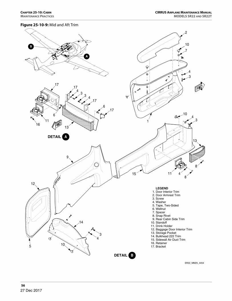
K. Mid and Aft Trim
(See Figure 25-10-9)
(1) Removal - Interior Door Trim
(a) Serials w/ Convenience Lighting: Disconnect door lock harness.1 Pull CONV LIGHTS circuit breaker.2 Remove kick plate. (Refer to 25-10)3 Remove mid console trim. (Refer to 25-10)4 Remove washer and bolt securing terminal ring to inboard gas strut attach
bracket.5 Remove cable tie securing door lock harness to fuselage.6 Identify and disconnect electrical connector from wire harness.
(b) Ensure cabin door is in fully open position.
• WARNING •
Ensure gas strut rod is not fully compressed during removal. Sudden extension of partially removed gas
strut rod could result in damage to airplane or injury to aircraft technician.
(c) Remove locking cap from gas strut inboard rod end.
(d) Position flat wrench around neck of ball stud between attach bracket and gas strut inboard rod end.
• CAUTION •
The ball stud snaps into four locking tabs integral to the gas strut rod end. Use caution during gas strut removal to avoid damaging locking tabs. If any one of the locking tabs cracks
or breaks loose, the rod end must be replaced.
(e) Gently pry gas strut inboard rod end off of ball stud.
(f) Remove interior door handle lever. (Refer to 52-10)
(g) Remove screws securing trim to door.
(h) Gently lift corner of door trim and release reclosable fasteners. Remove door trim.
27 Dec 2017

CIRRUS AIRPLANE MAINTENANCE MANUAL CHAPTER 25-10: CABINMODELS SR22 AND SR22T MAINTENANCE PRACTICES
51
(2) Installation - Interior Door Trim
(a) Place trim into position and press firmly on trim in areas of reclosable fasteners.
(b) Secure trim with screws.
(c) Install interior door handle lever. (Refer to 52-10)
(d) Ensure cabin door is in fully open position.
• WARNING •
Ensure gas strut rod is not fully compressed during installation. Sudden extension of partially installed gas strut rod could result in damage to airplane or injury to
aircraft technician.
(e) Visually inspect gas strut rod ends and locking caps for cracked or missing tabs, security, and general condition.
• CAUTION •
The ball stud snaps into four locking tabs integral to the gas strut rod end. Verify all four locking tabs are intact. If any one of the locking tabs is cracked or missing, the rod end must be
replaced.
(f) Position gas strut rod end to ball stud and press firmly to secure.
(g) Install locking cap to gas strut rod end.
(h) Serials w/ Convenience Lighting: Connect door lock harness.1 Install bolt and washer securing terminal ring to inboard gas strut attach
bracket.
• NOTE •
Secure wire so that harness can flex when door is opened.
2 Secure door lock harness to fuselage with cable tie.3 Connect electrical connector to wire harness.4 Install mid console trim. (Refer to 25-10)5 Install kick plate. (Refer to 25-10)6 Reset CONV LIGHTS circuit breaker.
27 Dec 2017

CHAPTER 25-10: CABIN CIRRUS AIRPLANE MAINTENANCE MANUALMAINTENANCE PRACTICES MODELS SR22 AND SR22T
52
(3) Removal - Sidewall Air Duct Trim
(a) Acquire necessary tools, equipment, and supplies.
(b) Remove door seal. (Refer to 53-40)
• CAUTION •
When cutting foam tape, ensure knife blade does not pene-trate too far and damage trim or fuselage skin.
(c) Lift forward edge of trim and slowly pull trim away from fuselage while cutting exposed foam tape with knife. Remove sidewall air duct trim.
(d) Remove residue from installation areas using knife and isopropyl alcohol. (Refer to 20-30)
(4) Installation - Sidewall Air Duct Trim
(a) Acquire necessary tools, equipment, and supplies.
(b) Apply 2-sided tape to sidewall air duct trim at locations in contact with installa-tion areas.
(c) Place trim into position and press firmly on trim in areas of foam tape.
(d) Install door seal. (Refer to 53-40)
Description P/N or Spec. Supplier Purpose
Putty Knife - Any Source Cut tape bond.
Plastic Scraper - Any Source Remove tape residue.
Isopropyl Alcohol 99% or higher purity
Any Source Clean installation area.
Cotton Cloth (clean and lint free) - Any Source Clean installation area.
Description P/N or Spec. Supplier Purpose
Foam Tape, 0.062 inch thick × 0.50 inch wide
- Any Source Secure trim.
27 Dec 2017
CIRRUS AIRPLANE MAINTENANCE MANUAL CHAPTER 25-10: CABINMODELS SR22 AND SR22T MAINTENANCE PRACTICES
53
(5) Removal - Rear Cabin Side Trim
(a) Remove screws securing upper section of rear cabin side trim to B-pillar trim.
(b) Lift forward edge of trim and release reclosable fasteners.
(c) Serials w/ Convenience Lighting: Disconnect connector from rear cabin side trim LED assembly. (Refer to 33-20)
(d) Remove rear cabin side trim.
(6) Installation - Rear Cabin Side Trim
(a) Serials w/ Convenience Lighting: Connect connector to rear cabin side trim LED assembly. (Refer to 33-20)
(b) Place trim into position and press firmly on trim in areas of reclosable fasteners.
(c) Secure upper section of rear cabin side trim to B-pillar trim with screws.
(7) Removal - Bulkhead 222 Trim
(a) Remove screws securing side sections of bulkhead 222 trim to fuselage.
(b) Remove screws securing upper section of bulkhead 222 trim to cabin headliner.
(c) Lift one corner of trim, and release reclosable fasteners. Remove trim.
(8) Installation - Bulkhead 222 Trim
(a) Place trim into position and press firmly on trim in areas of reclosable fasteners.
(b) Secure upper section of bulkhead 222 trim to cabin headliner with screws.
(c) Secure side sections of bulkhead 222 trim to fuselage with screws.
(9) Removal - Drink Holder
(a) For forward drink holder, remove snap rivets securing drink holder to sidewall air duct trim. Remove drink holder.
27 Dec 2017
CHAPTER 25-10: CABIN CIRRUS AIRPLANE MAINTENANCE MANUALMAINTENANCE PRACTICES MODELS SR22 AND SR22T
54
(b) For aft drink holder, remove retainers securing drink holder to attaching bracket. Remove drink holder.
(10) Installation - Drink Holder
(a) For forward drink holder, secure drink holder to sidewall air duct trim with snap rivets.
(b) For aft drink holder, secure drink holder to attaching bracket with retainers.
(11) Removal - Aft Storage Pocket
(a) Remove screws, washers, brackets, and wellnuts securing side sections of storage pocket to attaching brackets.
(b) Lift one corner of storage pocket, and release reclosable fasteners. Remove storage pocket.
(12) Installation - Aft Storage Pocket
(a) Place storage pocket into position and press firmly on storage pocket in areas of reclosable fasteners.
(b) Secure side sections of storage pocket to attaching brackets with screws, washers, brackets, and wellnuts.
(13) Removal - Forward Storage Pocket
(a) Remove snap rivets securing storage pocket to sidewall air duct trim. Remove storage pocket.
(14) Installation - Forward Storage Pocket
(a) Install snap rivets securing storage pocket to sidewall air duct trim.
27 Dec 2017
CIRRUS AIRPLANE MAINTENANCE MANUAL CHAPTER 25-10: CABINMODELS SR22 AND SR22T MAINTENANCE PRACTICES
55
(15) Removal - Baggage Door Trim
(a) Acquire necessary tools, equipment, and supplies.
(b) Remove door seal. (Refer to 53-40)
• CAUTION •
When cutting foam tape, ensure knife blade does not pene-trate too far and damage trim or fuselage skin.
(c) Lift forward edge of trim and slowly pull trim away from fuselage while cutting exposed foam tape with knife. Remove baggage door trim.
(d) Remove residue from installation areas using knife and isopropyl alcohol. (Refer to 20-30)
(16) Installation - Baggage Door Trim
(a) Acquire necessary tools, equipment, and supplies.
(b) Apply 2-sided tape to baggage door trim at locations in contact with installation areas.
(c) Place trim into position and press firmly on trim in areas of foam tape.
(d) Install door seal. (Refer to 53-40)
Description P/N or Spec. Supplier Purpose
Putty Knife - Any Source Cut tape bond.
Plastic Scraper - Any Source Remove tape residue.
Isopropyl Alcohol 99% or higher purity
Any Source Clean installation area.
Cotton Cloth (clean and lint free) - Any Source Clean installation area.
Description P/N or Spec. Supplier Purpose
Foam Tape, 0.045 inch thick × 0.50 inch wide
- Any Source Secure trim.
27 Dec 2017
CHAPTER 25-10: CABIN CIRRUS AIRPLANE MAINTENANCE MANUALMAINTENANCE PRACTICES MODELS SR22 AND SR22T
56
Figure 25-10-9: Mid and Aft Trim
BDETAIL
5
ADETAIL
2
34
7
10
1 34
10
415 11
13
8
8
17
B
LEGEND 1. Door Interior Trim 2. Door Armrest Trim 3. Screw 4. Washer 5. Tape, Two-Sided 6. Wellnut 7. Spacer 8. Snap Rivet 9. Rear Cabin Side Trim10. Standoff11. Drink Holder12. Baggage Door Interior Trim13. Storage Pocket14. Bulkhead 222 Trim15. Sidewall Air Duct Trim16. Retainer17. Bracket
43
SR22_MM25_4454
33
4
4
17
17
17
16
6
11
13
6
9
12
14
10
27 Dec 2017
CIRRUS AIRPLANE MAINTENANCE MANUAL CHAPTER 25-10: CABINMODELS SR22 AND SR22T MAINTENANCE PRACTICES
57
L. Headliner Trim
(See Figure 25-10-10)
(1) Removal - Cabin Headliner
(a) Remove door seal. (Refer to 53-40)
(b) Remove A-pillar trim. (Refer to 25-10)
(c) Remove B-pillar trim. (Refer to 25-10)
(d) Remove grab handle screws and loosen sunvisor screws. (Refer to 25-10)
(e) Remove grill from speaker.
(f) Remove screws securing speaker to headliner and disconnect speaker wires.
(g) Remove compass. (Refer to 34-20)
(h) Remove rear passenger light access panel and disconnect wires to switch and light.
(i) Remove upper windshield interior trim. (Refer to 25-10)
(j) Remove bulkhead 222 trim. (Refer to 25-10)
(k) Remove rear headliner trim. (Refer to 25-10)
(l) Serials w/ Convenience Lighting: Disconnect baggage lights from wire harness. (Refer to 33-30)
(m) Lift corners of cabin headliner and release reclosable fasteners. Remove head-liner.
(2) Installation - Cabin Headliner
(a) Place cabin headliner into position and secure. Press firmly on trim in areas of reclosable fasteners.
(b) Serials w/ Convenience Lighting: Connect baggage lights to wire harness. (Refer to 33-30)
(c) Install rear headliner trim. (Refer to 25-10)
(d) Install bulkhead 222 trim. (Refer to 25-10)
(e) Install upper windshield interior trim. (Refer to 25-10)
(f) Connect wires to rear passenger light access panel switch and light. Secure rear passenger light access panel.
(g) Install compass. (Refer to 34-20)
(h) Connect speaker wires and secure with screws.
27 Dec 2017

CHAPTER 25-10: CABIN CIRRUS AIRPLANE MAINTENANCE MANUALMAINTENANCE PRACTICES MODELS SR22 AND SR22T
58
(i) Install and secure speaker grill.
(j) Secure grab handles with screws and tighten sunvisor screws. (Refer to 25-10)
(k) Install B-pillar trim. (Refer to 25-10)
(l) Install A-pillar trim. (Refer to 25-10)
(m) Install door seal. (Refer to 53-40)
(3) Removal - Rear Headliner Trim
(a) Remove screws securing upper section of rear headliner trim to cabin headliner trim.
(b) Remove screws securing lower section of rear headliner trim to rear cabin side trim.
(c) Lift corners of rear headliner trim and release reclosable fasteners. Remove rear headliner trim.
(4) Installation - Rear Headliner Trim
(a) Place rear headliner trim into position and secure upper section of trim with screws to cabin headliner trim.
(b) Secure lower section of trim with screws to rear cabin side trim.
(c) Press firmly on trim in areas of reclosable fasteners.
(5) Removal - Upper Windshield Trim
(a) Remove compass. (Refer to 34-20)
(b) Remove A-pillar trim. (Refer to 25-10)
(c) Lift corners of upper windshield trim and release reclosable fasteners.
(d) Disconnect wires to switches and lights. Remove upper windshield trim.
(6) Installation - Upper Windshield Trim
(a) Connect wires to switches, compass, and lights in upper windshield trim.
27 Dec 2017

CIRRUS AIRPLANE MAINTENANCE MANUAL CHAPTER 25-10: CABINMODELS SR22 AND SR22T MAINTENANCE PRACTICES
59
(b) Place upper windshield trim into position and secure. Press firmly on trim in areas of reclosable fasteners.
(c) Install A-pillar trim. (Refer to 25-10)
(d) Install compass. (Refer to 34-20)
(7) Removal - A-Pillar Trim
(a) Remove sunvisor blade. (Refer to 25-10)
(b) Remove screws securing A-pillar trim to upper windshield trim and lower wind-shield trim.
(c) Lift corners of trim and release reclosable fasteners. Remove trim.
(8) Installation - A-Pillar Trim
(a) Place A-pillar trim into position and press firmly on trim in areas of reclosable fasteners.
(b) Secure upper section of A-pillar trim with screws to upper windshield trim.
(c) Secure lower section of A-pillar trim with screws to lower windshield trim.
(d) Install sunvisor blade. (Refer to 25-10)
(9) Removal - B-Pillar Trim
(a) Remove screws securing B-pillar trim to cabin headliner and rear cabin side trim.
(b) Lift corners of trim and release reclosable fasteners. Remove trim.
(10) Installation - B-pillar Trim
(a) Place B-pillar trim into position and press firmly on trim in areas of reclosable fasteners.
(b) Secure upper section of B-pillar trim with screws to cabin headliner.
(c) Secure lower section of B-pillar trim with screws to rear cabin side trim.
(d) Press firmly on trim in areas of reclosable fasteners.
27 Dec 2017
CHAPTER 25-10: CABIN CIRRUS AIRPLANE MAINTENANCE MANUALMAINTENANCE PRACTICES MODELS SR22 AND SR22T
60
(11) Removal - Coat Hook
(a) Remove screw securing coat hook to cabin headliner trim.
(12) Installation - Coat Hook
(a) Position coat hook to cabin headliner trim and secure with screw.
(13) Removal - Garment Bracket
(a) Remove screws and washers securing garment bracket to cabin headliner trim.
(14) Installation - Garment Bracket
(a) Position garment bracket to cabin headliner trim and secure with screws and washers.
27 Dec 2017

CIRRUS AIRPLANE MAINTENANCE MANUAL CHAPTER 25-10: CABINMODELS SR22 AND SR22T MAINTENANCE PRACTICES
61
Figure 25-10-10: Headliner Trim
1316
ADETAIL
1
1915
2021
1516
15
12
A-PILLAR TIE(REF)
SR22_MM25_4455
HINGE POCKET(REF)
HINGE POCKET(REF)
4
2
3
5 8
9
10
11
LEGEND 1. Left A-Pillar Trim 2. Upper Windshield Interior Trim 3. Right A-Pillar Trim 4. Screw 5. Cabin Headliner Interior Trim 6. Right Rear Passenger Light Trim Panel 7. Left Rear Passenger Light Trim Panel 8. Right B-Pillar Trim 9. Right Rear Headliner10. Left Rear Headliner11. Left B-Pillar Trim12. Standoff13. Bracket14. Light Shield15. Washer16. Nut17. Garment Bracket18. Coat Hook19. Spacer20. Pad, Hook21. Pad, Loop
18
1615
4
4
15
15
4
17
27 Dec 2017
CHAPTER 25-10: CABIN CIRRUS AIRPLANE MAINTENANCE MANUALMAINTENANCE PRACTICES MODELS SR22 AND SR22T
62
M. Floor Covering
(See Figure 25-10-11)
(1) Removal - Floor Covering
(a) Lift corner of carpet and pull carpet from floor to release reclosable fasteners.
(2) Installation - Floor Covering
(a) Clean floor surface and reclosable fasteners using a whisk broom and a vacuum cleaner.
(b) Place carpet into position and press firmly on carpet in areas of reclosable fasteners.
27 Dec 2017

CIRRUS AIRPLANE MAINTENANCE MANUAL CHAPTER 25-10: CABINMODELS SR22 AND SR22T MAINTENANCE PRACTICES
63
Figure 25-10-11: Floor Covering
16
19
518
17
20
227
15
1
13
14
2
3
4
6
8
9
1011
12
LEGEND 1. LH Forward Carpet 2. Chafe Plate, Rudder Pedals 3. Hook Tape 4. RH Forward Carpet 5. Inner Spar Filler 6. Baggage RH Side Carpet 7. Baggage LH Side Carpet 8. Baggage Door Carpet 9. Baggage Floor Carpet10. Rear Seat Side Carpet, LH11. Rear Seat Center Carpet12. Rear Floor Carpet13. Wellnut14. Screw15. Chafe Plate, Baggage Door16. Spar Cover Carpet, LH17. Spar Cover Carpet, RH18. Outer Spar Filler, RH19. Outer Spar Filler, LH20. Rear Seat Side Carpet, RH21. Baggage RH Side Carpet22. Bulkhead 222 Carpet
SR22_MM25_4456
27 Dec 2017
CHAPTER 25-10: CABIN CIRRUS AIRPLANE MAINTENANCE MANUALMAINTENANCE PRACTICES MODELS SR22 AND SR22T
64
N. Sunvisor Blade
(See Figure 25-10-12)
(1) Removal - Sunvisor Blade
(a) Remove screw securing sunvisor blade and grommet to mount.
(2) Installation - Sunvisor Blade
(a) Position grommet and sunvisor blade to mount and secure with screw.
O. Sunvisor Mount
(See Figure 25-10-12)
(1) Removal - Sunvisor Mount
(a) Remove A-pillar trim. (Refer to 25-10)
(b) Remove screws securing sunvisor mount to fuselage.
(2) Installation - Sunvisor Mount
(a) Position sunvisor mount to fuselage and secure with screws.
(b) Install A-pillar trim. (Refer to 25-10)
27 Dec 2017
CIRRUS AIRPLANE MAINTENANCE MANUAL CHAPTER 25-10: CABINMODELS SR22 AND SR22T MAINTENANCE PRACTICES
65
P. Grab Handle
(See Figure 25-10-12)
(1) Removal - Grab Handle
(a) Remove A-pillar trim. (Refer to 25-10)
(b) Serials w/o optional headset hook: Remove screws securing grab handle to fuse-lage.
(c) Serials w/ optional headset hook:1 Remove headset hook. (Refer to 25-10)2 Remove screw securing inboard end of grab handle to fuselage.3 Remove screws securing outboard end of grab handle to fuselage.
(2) Installation - Grab Handle
(a) Serials w/o optional headset hook: Position grab handle to fuselage and secure with screws.
(b) Serials w/ optional headset hook:1 Position outboard end of grab handle to fuselage and secure with screws.2 Position inboard end of grab handle to fuselage and secure with screw.3 Install headset hook. (Refer to 25-10)
(c) Install A-pillar trim. (Refer to 25-10)
Q. Headset Hook
(See Figure 25-10-12)
(1) Removal - Headset Hook
(a) Remove screw securing headset hook to grab handle.
(2) Installation - Headset Hook
(a) Position headset hook to grab handle and secure with screw.
27 Dec 2017
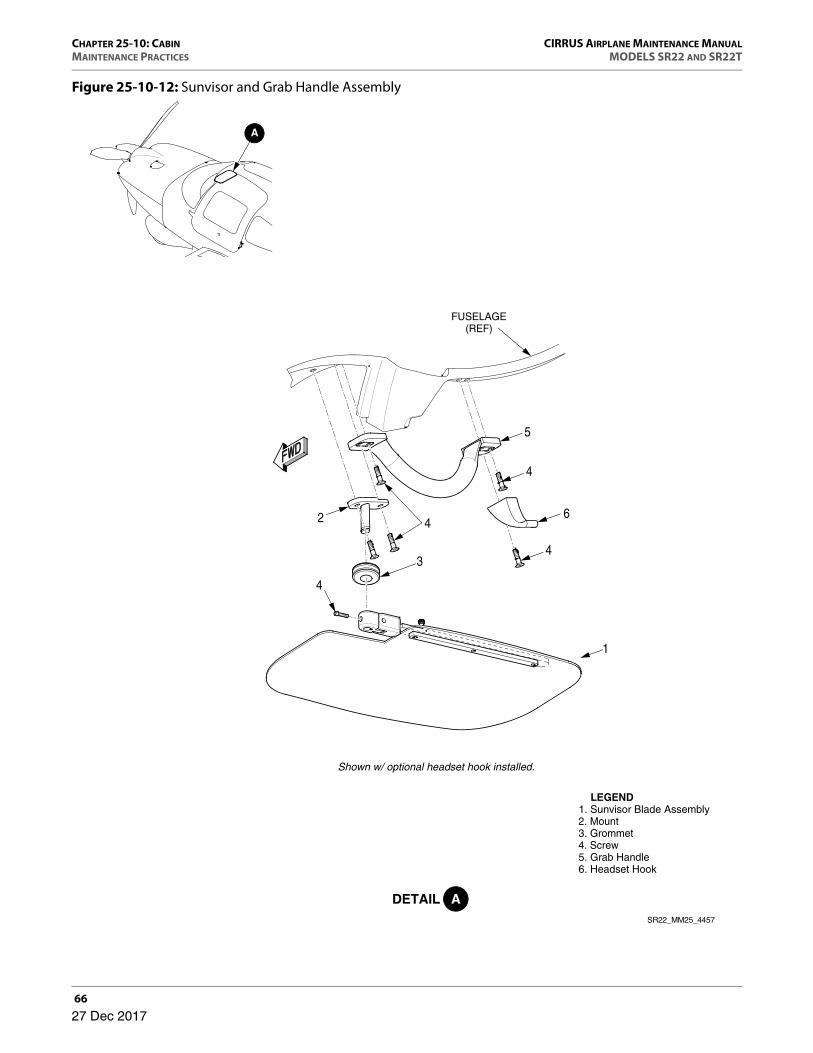
CHAPTER 25-10: CABIN CIRRUS AIRPLANE MAINTENANCE MANUALMAINTENANCE PRACTICES MODELS SR22 AND SR22T
66
Figure 25-10-12: Sunvisor and Grab Handle Assembly
1
4
4
3
5
2
4
LEGEND 1. Sunvisor Blade Assembly 2. Mount 3. Grommet 4. Screw 5. Grab Handle 6. Headset Hook
SR22_MM25_4457
Shown w/ optional headset hook installed.
FUSELAGE(REF)
6
4
27 Dec 2017

CIRRUS AIRPLANE MAINTENANCE MANUAL CHAPTER 25-10: CABINMODELS SR22 AND SR22T MAINTENANCE PRACTICES
67
R. Radio Module Assembly
(See Figure 25-10-13)
(1) Removal - Radio Module Assembly
(a) Set BAT 1, BAT 2, and AVIONICS switches to OFF positions.
(b) Pull STARTER and FUEL PUMP circuit breakers.
(c) Remove LH, RH, and center bolster trim. (Refer to 25-10)
(d) Loosen screws securing bolster plate to LH bolster panel. (Refer to 31-10)
(e) Remove LH mid console circuit breaker trim. (Refer to 25-10)
(f) Remove RH mid console trim. (Refer to 25-10)
(g) Remove cabin floor access panel CF8. (Refer to 6-00)
(h) Remove glareshield. (Refer to 25-10)
(i) Remove MFD. (Refer to 31-60)
• NOTE •
Label avionics and communication units to ensure proper reinstallation. Failure to install avionics and communica-tion units as originally configured will require calibration
and setup procedures to be performed.
(j) Remove GMC 707 mode controller. (Refer to 22-10)
(k) Remove audio panel. (Refer to 23-50)
(l) Remove screws and washers securing front of radio module assembly to bolster panel.
(m) Remove screws and washers securing sides of radio module assembly to center console.
• CAUTION •
Use caution while pulling radio module assembly out to prevent damaging wire harnesses and electrical connectors.
(n) Carefully slide radio module assembly out of center console.
(o) Remove radio module assembly from airplane.
(2) Installation - Radio Module Assembly
(a) Carefully slide radio module assembly into center console.
27 Dec 2017

CHAPTER 25-10: CABIN CIRRUS AIRPLANE MAINTENANCE MANUALMAINTENANCE PRACTICES MODELS SR22 AND SR22T
68
(b) Install screws and washers securing sides of radio module assembly to center console.
(c) Install screws and washers securing front of radio module assembly to bolster panel.
(d) Install audio panel. (Refer to 23-50)
(e) Install GMC 707 mode controller. (Refer to 22-10)
(f) Install MFD. (Refer to 31-60)
(g) Install glareshield. (Refer to 25-10)
(h) Install cabin floor access panel CF8. (Refer to 6-00)
(i) Tighten screws securing bolster plate to LH bolster panel. (Refer to 31-10)
(j) Install RH mid console trim. (Refer to 25-10)
(k) Install LH mid console circuit breaker trim. (Refer to 25-10)
(l) Install LH, RH, and center bolster trim. (Refer to 25-10)
(m) Reset STARTER and FUEL PUMP circuit breakers.
27 Dec 2017

CIRRUS AIRPLANE MAINTENANCE MANUAL CHAPTER 25-10: CABINMODELS SR22 AND SR22T MAINTENANCE PRACTICES
69
Figure 25-10-13: Radio Module Assembly Installation
23
4
ENGINE CONTROLSUPPORT BRACKET
(REF)
1
BOLSTER PANEL(REF)
BOLSTERGAUGE PLATE
(REF)
CENTER CONSOLE(REF)
2
3 2
SR22_MM25_4985
LEGEND 1. Radio Module Assembly 2. Washer 3. Screw 4. Spacer
3
27 Dec 2017

CHAPTER 25-10: CABIN CIRRUS AIRPLANE MAINTENANCE MANUALMAINTENANCE PRACTICES MODELS SR22 AND SR22T
70
S. EMI Shielding
(See Figure 25-10-14)
(1) Removal - EMI Shielding
(a) Set BAT 1, BAT 2, and AVIONICS switches to OFF positions.
(b) Remove glareshield. (Refer to 25-10)
(c) Remove screws and washers securing EMI shield to instrument panel. Remove EMI shield from airplane.
(2) Installation - EMI Shielding
(a) Slide forward edge of EMI shield under mounting clips.
(b) Position EMI shield to instrument panel and secure with screws and washers.
(c) Install glareshield. (Refer to 25-10)
27 Dec 2017

CIRRUS AIRPLANE MAINTENANCE MANUAL CHAPTER 25-10: CABINMODELS SR22 AND SR22T MAINTENANCE PRACTICES
71
Figure 25-10-14: EMI Shields Installation
1
2
3 2
32
3
23
1
MOUNTINGCLIP(REF)
CONSOLE(REF)
SR22_MM25_4987
LEGEND 1. EMI Shield 2. Screw 3. Washer
ADETAIL
A
27 Dec 2017

CHAPTER 25-10: CABIN CIRRUS AIRPLANE MAINTENANCE MANUALMAINTENANCE PRACTICES MODELS SR22 AND SR22T
7227 Dec 2017
Intentionally Left Blank