circularly polarized uhf up- and downlink antennas integrated with cubesat solar panels"
TRANSCRIPT
Two Types of Conformal Antennas
for Small Spacecrafts
Salahuddin Tariq
Electrical and Computer Engineering Department, Utah State
University,Logan,UT 84322

Study # 1: Auroral Spatial Structures Probe (ASSP )
Project

Auroral Spatial Structures Probe (ASSP ) Project
• A mission to measure small scale E-field
variations during breakup aurora and
geomagnetically active conditions of
upper atmosphere.
• Sounding rocket will have six identical
sub-payloads.
• Follows the work of a previous graduate student.
Sounding rocket sub-payload

Design Requirements for ASSP Project
Specification Description Comments
Diameter -Outside < 6.5 inch I.D.
Diameter-Inside 6.0 inch I.D. Surface mount onto a 6'' diameter cylinder
Height 4.0 inches tall Axial Length
Thickness < .25 inch
VSWR-S-band2.0 :1 Max ( 2210MHz to
2230MHz)Typical = 1.5 :1
VSWR-GPS< 1.5:1 @ 1575.42MHz Center
Frequency< 1.5 VSWR across 10MHz Bandwidth
S-band frequencyCentre at 2220 MHz ( 10MHz
BW)2210MHz to 2230MHz
GPS Frequency 1575.42MHz RHC Polarization
RF Connectors S-bandSMA Male "Flying Lead Coax
Cable"Cable Length TBD
RF Connectors GPSSSMA Male "Flying Lead Coax
Cable"Cable Length TBD
S-band Polarization Linear
GPS-Polarization RHC See Note #1
Material Non-magnetic Nickel Plating NOT allowed
Filter Notch Filter on GPS antennas 40dB rejection of S-band
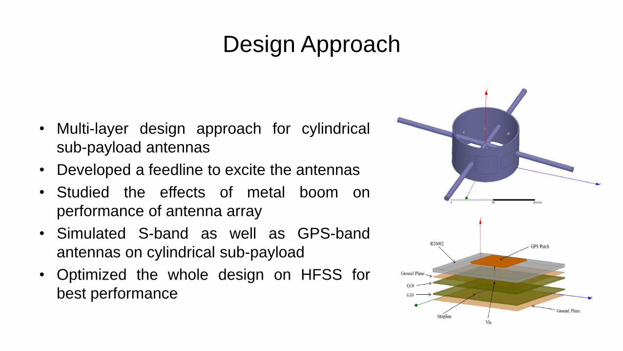
Design Approach
• Multi-layer design approach for cylindrical
sub-payload antennas
• Developed a feedline to excite the antennas
• Studied the effects of metal boom on
performance of antenna array
• Simulated S-band as well as GPS-band
antennas on cylindrical sub-payload
• Optimized the whole design on HFSS for
best performance

Final Design of S-Band Antenna Array
Model of Final Design in HFSS
• Each boom has length = 333mm
• Structure has 32 air holes for
mounting different screws and
components
• Substrate material is Roger’s
RT/Duriod 6002 for both the
feedline design as well as
antennas
Return Loss of 4-GPS Band Antenna Array

Gain Plots of S-band Antenna Array
3-D Gain Plot of 4-S Band Antennas
2-D Gain Plot for theta = 90°
2-D Gain Pattern Cuts for all Phi (0° to 360° )3-D Gain Plot of 4-S Band Antennas ( Another View )

VSWR and Isolation between GPS and S-band
Antennas
VSWR of 4-S Band Antennas Isolation Between Feedlines of S-Band and GPS Antennas

Final Design of GPS-band Antenna Array
Return Loss of 4-GPS Band Antenna Array
3-D Gain Plot of 4 GPS-band Antennas
3-D Gain Plot of 4 GPS-band Antennas ( Another View)

2D Gain, Axial Ratio and VSWR Plots
2-D Gain Plot for theta = 90°
Axial Ratio at 1.575GHzVSWR Plot at 1.575GHz
2-D Gain cuts for all Phi ( 0 to 360)

Study # 2: Dual Band Circularly Polarized UHF
Slot Antenna Design for a 3U CubeSat

Design Requirements
• To design the slot antennas for uplink and downlink frequencies of 485MHz
and 500MHz respectively on 3U CubeSat surface
• To obtain a method of circularly polarized radiation for both uplink and
downlink Frequencies
• To obtain impedance bandwidth of 10MHz for both uplink and downlink
frequencies
• To make the final design practically implementable for fabrication after
finishing the simulations on HFSS

Challenges
• A 3U CubeSat is form of a miniaturized satellite having a volume of 10cm X
10cm X 30cm;
• As per my recent study, there is NO antenna designed for CubeSat that
operates in UHF ( 400MHz- 500MHz) range;
• There is a competition between limited surface area and efficiency of
antenna, especially when solar panels have to be integrated on CubeSats;
• To get a good impedance bandwidth as well as circular polarization;
• The design needs to be shielded from inside so that we can place electronics
equipment but it conflicts with getting good impedance bandwidth.

Solution and Design Features
• A unique design which is totally conformal to the surface and does not have anymoving parts;
• Impedance bandwidth of 10MHz was achieved using cavity backed slot antennadesign;
• These type of slot antennas can be designed to operate as low as 300MHz by justchanging the length of slot;
• Integration of Solar panels is possible and slots take a minimum surface area;
• Circular polarization was achieved using T-junction feedline;
• This design is modular in approach and two or more 1.5U CubeSats can be stackedup to have multi-band functionality;
• The design is shielded from inside with a copper wall on all the four sides;

Solution and Design Features
• The design was extensively studied and simulated on HFSS beforefabrication;
• This design was fabricated in our facilities and results came out to bevery close to what we predicted on simulations;
• A paper detailing this project was accepted in APS/URSI 2015conference recently;
• Our Space Dynamics Lab (SDL) is also showing keen interest in thisdesign as it can replace conventional whip/wire type antennas that arecurrently employed in CubeSat missions.

Modelling in HFSS and Simulation Results
Reflection coefficient of lower slot (Center frequency = 485 MHz and 10dB impedance BW is
more than 10MHz)
3-D gain plot for lower slot
Final model in HFSS

Fabrication Process

Final Prototype and Measured Results
Final fabricated prototype of wraparound meandered slot Measured radiation pattern

Reflection Coefficient and VSWR Results
Reflection coefficient ( -23dB at 486MHz) VSWR ( 1.1 at 486 MHz)