circular of the bureau of standards no. 17 2nd edition
TRANSCRIPT

DEPARTMENT OF COMMERCE AND LABOR
CircularOP THE
of Standards
MAGNETIC TESTING
WASHINGTONGOVERNMENT PRINTING OFFICE
1910


DEPARTMENT OF COMMERCE AND LABOR
CircularOF THE
Bureau of StandardsS. W. STRATTON, Director
No. 17
MAGNETIC TESTING
[2d Edition]
Issued December 1, 19)10
WASHINGTONGOVERNMENT PRINTING OFFICE
1910


MAGNETIC TESTING
CONTENTSPage
1. Scope of the Magnetic Testing .
. 32. Description of Work 4
(a) General 4(b ) Normal induction and hysteresis
loop 5i) . Normal induction 5ii) . Hysteresis loop 5
iii) . Selection of test points. . 6iv) . Standard specimens .... 7v). Form of specimen
7(c) Hysteresis and eddy current
losses 8
3. Technical Papers on MagneticWork 11
1. SCOPE OF THE MAGNETIC TESTING
Permeability and hysteresis tests are made by the ballistic method onmagnetic materials in the form of round or rectangular bars and sheets.
For these tests two specimens of each sample, at least 25 cm, and preferably
35 cm in length, should be furnished. The permissible cross section is
determined by the dimensions of the holes of the coils and yokes used.
The apparatus on hand at present will receive round rods of the following
diameters
:
0.95 cm (yi inch).
1.00 cm1.27 cm (X inch).
Rectangular bars may be of any section which will pass through a hole
1.27 cm in diameter. Sheet metal 5 cm wide, or under, and of the samelength as for rods, may be used.
For these measurements two rods or strips of the material to be tested
have their ends joined by two soft iron yokes so as to form the four sides of
a rectangle. Each bar is surrounded by a magnetizing and a test coil. Thechange in the magnetic flux embraced by the test coil when the magnetizingcurrent is altered is measured ballistically. Further details are given below.
Tests of nonmagnetic materials, such as are used for chronometers andother instruments, and feebly magnetic materials and investigations onmagnetic properties at high and low temperatures can also be made. Bis-
muth spirals, for measurement of magnetic fields, will be calibrated.
66 1990—10
Page4. Regulations n
(a) Application for test 1
1
( b
)
Identification marks n(c) Shipping directions 11
(d
)
Address n( e) Remittances 12
5. Schedules of Fees.. 12Schedule 90. Short ballistic test ... 12Schedule 91. Complete ballistic test 12Schedule 92. Standard bars 12Schedule 93. Wattmeter measure-ments 13
Schedule 94. Miscellaneous 13
3

4 Circular of the Bureau of Standards
The Bureau is prepared to calibrate permeameters and other apparatus
used in magnetic measurements and to make investigations on the magneticproperties of materials.
A limited number of bars of carefully aged iron and steel have beenprepared and will be supplied to testing laboratories and manufacturers as
standards, at little more than the amount of the fee for testing.
Wattmeter tests for energy losses due to alternating magnetization are car-
ried out upon sheet iron and steel, such as is used in the cores of transformers.
A special apparatus designed for this purpose is described below. This
serves to determine the losses due to hysteresis and eddy currents. A curveshowing the relation between the flux density in the test specimen and the
wattless component of magnetizing current can also be furnished whendesired. Tests to determine the aging quality of this material are also
carried on. Not less than 5 pounds (2.5 kg) should be submitted. Thelosses are measured at 60 cycles and 10 000 gausses, unless otherwise speci-
fied, and the results are accurate within 2 per cent.
Transformers are tested for core loss under normal working conditions;
and by the measurement of resistances and impedance in addition the effi-
ciencies and regulation can be computed. For tests of instrument trans-
formers, including measurements of ratio, phase angles, regulation, etc., see
Bureau Circular No. 20.
2. DESCRIPTION OF WORK(a) GENERAL
The induction which a bar of iron or steel will assume under a givenmagnetizing force depends upon the previous magnetic condition of thespecimen, and upon the rate of change from one magnetic state to another.
It is modified by the presence of mechanical vibration and depends to
some extent on temperature. It is therefore desirable to state the conditions
under which the test is made.All the ordinary tests on magnetic material except aging are made at a
constant temperature of 250C. This is in view of the fact that all the mag-
netic quantities, including the normal induction, the hysteresis loop, and thelosses due to hysteresis and eddy currents, depend upon the temperature of
the specimen. The relation is not a simple one, and is not the same for all
materials. In view of these facts, it seems desirable to make all such meas-urements at a fixed temperature.
It is important that there be no mechanical vibration of the specimenduring the test. Such vibrations tend to give an induction greater thannormal for increasing magnetizing forces, and too small values for decreasingforces. Hence, the test specimen is always protected from mechanicalvibrations in ballistic measurements.
The results found for rolled sheets usually depend upon whether thematerial is magnetized parallel to the direction of rolling or at right angles
to this direction. When not otherwise specified and the dimensions of sheets

Magnetic testing5
submitted permit it, the test pieces will be so cut that the flux traverseshalf of them parallel to the direction of rolling, and half normal thereto.
The measurement of flux density requires a knowledge of the cross-sectional area of the specimen. For rods and bars the cross section is deter-mined from the dimensions. In sheet metal, however, it is not determinedby direct measurement, but from values of mass, length, and density. Thedensity of each specimen is experimentally determined, as experience showsthat the assumption of any specified value introduces an uncertainty in theresult which is greater than the inaccuracy of the magnetic measurements.
(6) NORMAL INDUCTION AND HYSTERESIS LOOP
i) . Normal Induction.—If a bar of thoroughly demagnetized iron is
subjected to a magnetizing force, it experiences a certain induction. Thisinduction will be greater if the magnetizing force is applied suddenly thanfor a slower growth of magnetizing current. If the magnetizing force is
repeatedly applied and removed, the values of the induction obtained differ
somewhat. If the magnetizing force is reversed, a change of inductionapproximately twice the preceding values is obtained. For the first fewreversals the change of induction is not constant, but becomes so after alarge number of reversals. One-half this constant value of the change in
induction on reversal of the magnetizing force is the normal induction, andthe locus of such points is the curve of normal induction.
The magnetic properties of a piece of iron or steel may be consideredas defined by the curves of normal induction and hysteresis. Before deter-
mining the normal induction data, it is necessary that the specimen befreed from its previous magnetization. This is accomplished by subjecting
it to a cyclic magnetizing force of one period per second, which is gradually
reduced from an initial value, which carries the induction well beyond the
point of maximum permeability to a final value somewhat lower than the
lowest induction to be studied.
After thorough demagnetization, the lowest magnetizing force to beused is applied and reversed many times, until the iron is brought to a cyclic
magnetic state. The induction is then measured and the next higher valueof the magnetizing force applied in the same manner. This process is
repeated until the required number of points is determined. This is a
somewhat laborious operation, but has been found necessary in order to
obtain reliable results.
ii) . Hysteresis Loop.—Before determining the hysteresis loop, the
iron is demagnetized as above, and the magnetizing force is applied andincreased until the iron is brought up to the maximum induction for whichthe loop is required. This magnetizing force is repeatedly reversed until
the iron is in a normal condition. The magnetizing force is now reduced
from its maximum value to a lower one, and the change in magnetic induc-
tion corresponding to the change in force is noted. After determining this
pair of values, the maximum magnetizing force is again applied and the
iron once more brought back to a normal magnetic condition. It is not

6 Circular of the Bureau of Standards
necessary, however, to repeat the process of demagnetization. Anotherpoint is then determined in the same manner a$ the first. Points corre-
sponding to negative values, of the magnetizing force are obtained bysimultaneously reversing and reducing the magnetizing force. Before eachdetermination of a point on the loop the iron is brought back to its normalcondition.
This method of measuring the magnetic constants differs somewhatfrom the old “step by step” method which is still employed in many of
the modern commercial permeameters. It has the advantage of making the
measurement under more nearly the same conditions that occur in com-mercial practice, and is practically free from the effects of magnetic viscosity.
Further, it is possible to get more consistent results by this method thanby the older one, as the effects of imperfect initial demagnetization are not
so serious. The numerical data obtained by these two methods are notidentical, and in publishing results of work of the highest precision it is
desirable to specify the method of measurement.iii). Selection of Test Points.—In defining the magnetic properties of
a bar of iron or steel, it is neither necessary nor practicable to give completenormal and hysteresis data for all values of the magnetizing force. Certain
data may be chosen as characteristic and the magnetic properties inferred
from these.
The upper limit of the magnetizing force to be applied is determinedby the heating of the magnetizing coil. The magnetic constants for high
values of the magnetizing force change slowly and quite regularly, and for
a considerable range may be obtained by extrapolation from the data of
lower magnetizations. However, magnetizing forces up to 300 gausses canbe employed. This upper limit of 300 has reference to the magnetizingforce employed in the determination of normal induction data. It is notdesirable to carry the cyclic induction measurements through such a widerange. A single hysteresis loop having a maximum induction of 10 000gausses gives a close index to the hysteretic properties at all inductions.
In some cases it might be desirable to supplement these data by the residual
induction and coercive force at other values of the maximum induction.
It is, of course, desirable that the number of observations be as small
as possible and yet yield the required continuity of data. For most pur-
poses the magnetizing forces required to produce inductions of 5000, 10 000,
15 000, and 20 000 would indicate clearly enough the shape of the normalinduction curve. If one is interested in some particular range, measure-ments in this region could be taken closer together—for instance, every1000 gausses—or the measurements may be confined to one particular
region. A single pair of data may be sufficient for some purposes.
In the hysteresis data, likewise, the labor of measurement is reducedto a minimum by drawing the curve from the three principal points, namely,the tip of the magnetic cycle, the residual induction remaining when the
magnetizing force is removed, and the coercive force or the magnetizingforce required to reduce the induction to zero.

Magnetic testingj
Such a determination of four points on the normal induction curve andthree points on the hysteresis curve gives a fair idea of the magnetic prop-erties of a sample of iron. If several specimens are thus examined atcorresponding points, it is possible to make comparisons of the differentspecimens and classify them into different grades without drawing completeinduction curves as would be necessary if the different specimens are testedat irregular points.
iv) . Standard Specimens.—If a bar is to be used as a standard ofcomparison, or for the purpose of calibrating a permeameter, it is necessaryto determine a considerable number of points of the curve in the regionwhere the apparatus is to be used. Such measurements should be takenwith greater care than those on a specimen typical of a large lot whichindividually may differ considerably from the mean.
In measurements of the highest precision, the magnetic circuit consistsof two rods joined at their ends by two soft iron yokes. The magnetomotiveforce is applied by means of two solenoids and a set of compensating coils.
The magnetizing current in each solenoid is capable of independent adjust-ment until the fluxes in the two rods are equal. The compensating coils
are distributed over the four joints of the magnetic circuit and the currentis adjusted so that there is no magnetic leakage between the middle andends of the test specimens. When the magnetic flux has thus been rendereduniform throughout the circuit the true magnetic force and induction maybe determined by the ballistic method. 1
v) . Form of Specimen.—The labor of a test is reduced and the precision
increased by having a certain degree of uniformity in the test specimens.The minimum length of test piece in the ballistic tests is 25 cm (10 inches).
A length of 35 cm (14 inches),however, is preferred, as more precise measure-
ments can be made on the longer specimen. Round rods may be 1 cm or
1.27 cm [y2 inch) or 0.95 cm inch) in diameter. Specimens of any uniformsection which have one pair of parallel sides and will pass through a roundhole 1.27 cm {y2 inch) in diameter may be submitted.
Two rods of the same material should be submitted for each test. Forsingle rods and for specimens of other dimensions than those indicated aspecial fee is charged.
For sheet metal the test material consists of four strips 5 cm (2 inches)
wide, two cut parallel and two perpendicular to the direction of rolling.
The material submitted should be chosen from different parts of the sheet
and of sufficient size to permit the final cutting to size being done at this
laboratory. For this purpose four strips 7.5 by 40 cm (3 by 16 inches) are
satisfactory. Crayon lines should be drawn on each specimen parallel to the
direction of rolling.
1A fuller account of the arrangement of the magnetic and electric circuits, of the manner of
securing uniformity of flux, and of other details of the ballistic method employed is found in
Technical Paper No. 117, reprinted from the Bulletin of the Bureau of Standards, Vol. 6, No. 1.

8 Circular of the Bureau of Standards
(c) HYSTERESIS AND EDDY CURRENT LOSSES
The total losses due to the combined effects of hysteresis and eddy cur-
rents in sheet iron and steel when subjected to a sine wave of alternating
magnetic flux are measured by the method described in full in Technical
Paper No. 109 (from Bulletin of this Bureau, vol. 5, pp. 453-482). This
paper will be mailed on request. For this test ten small sheets approxi-
mately 30 cm (12 inches) square are required. These are cut at this
Bureau into strips 5 by 25.4 cm and made up into four bundles, which formthe four sides of a square magnetic circuit. The arrangement is similar to
that proposed by Epstein, but differs from it in having good magnetic joints
at the corners of the square. It is thus possible to secure an accuracy of 1
or 2 per cent with a smaller quantity of material, and yet without appreciable
distortion of the wave form. In the paper cited above it is shown that the
sheet material in common use varies very widely in quality, and the quality
is not closely related to the cost. Some of the results are given in Tables
I and II.
TABLE I
Hysteresis and Eddy Current Losses
Ordinary steel
Desig-nation
1
Thickness
Ergs per gram per cycleWatts per pound at 60 cycles
AND 10 000 GAUSSES10 000 gausses 5000 gausses
cm 6o~I
3o~Hyster-
esis
Eddycur-rents
6o~ 3°~Hystere-
sis
Eddycur-rents
Eddy cur-rents for
gage 29*
Hystere-sis
Total
E 0. 0476 971 853 735 236 3°4 2 75 246 58 O. 36 2 . OO 2.36
F 0. 0280 766 716 666 ICO 247 233 - 5 220 2 7 0. 44 I. 81 2.25
G 0. 0394 773 668 563 210 247 220 193 54 O. 47 I- 53 2.00
H 0. 0307 558 485 412 146 i 77 - 5 158 138.5 39 o. 54 I. 12 1.66
J 0. 0318 543 442 34 i 202 166. 5 i39 hi. s 55 0. 70 o-93 , 1.63
K 0. 0282 5 i8 456 394 124 162 146 130 3 2 0. 54 1. 07 1.61
L 0. 0346 565 473 381 184 I 75 150 I2 5 50 o- 535 1-035 1.57
B,.... 0. 0338 554 454 354 200 i 73 144 - 5 116 57 0. 61 0. 96 1.57
M o. 033 s 55° 461 37 2 178 i 73 150 127 46 o- 55 1. 01 1.56
N 0. 0340 53 i 426 3 21 210 161 133 105 56 0. 63 0. 87 1.50
P 0. 0437 5 l8 426. 334 184 i 57 132 107 5° 335 0. 91 1.24
* In order to make a fair comparison of quality, the eddy current loss has been computed in each case for a thickness of
0.0357 cm (U. S. standard gage No. 29) on the assumption that the eddy current loss is proportional to the square of thethickness.
Magnetic testing 9
TABLE II
Hysteresis and Eddy Current Losses
Silicon steel
Desig-nation.
Thickness
Ergs per GRAM PER CYCLE
Watts per pound at 6o cyclesAND 10 000 GAUSSES
10 000 gausses 5000 gausses
cm 6o~ 3°~Hyster-
esis
Eddycur-rents
6o~ 3o~Hystere-
sis
Eddycur-rents
Eddy cur-rents for
gage 29*
Hystere-sis
Total
Q 0. 0361 357 330 303 54 1 13 I0 5- 5 98 15 0. 14 O. 82 0.96R. . . . 0. 0315 33° 309 288 42 104 98. 5 93 II O. 15 O. 78 0.93
S 0. 0452 350 3 I4 278 72 108 99 90 18 0. 12 O. 76 0.88T 0. 0338 3 IQ 280 25° 60 96 87 78 18 O. 18 O. 68 0.86U 0. 0346 3 12 291 270 42 98 92 86 12 O. 12 O. 74 0.86
V 0. 0310 298 275 251 47 92 85-5 79 13 0. 17 0. 68 0.85
w 0. 0305 240 218 197 43 74 - 7 68.5 62. 3 12. 4 O. 16 0. 54 0.70X 0. 0430 265 232 200 65 80.8 72- 5 64. 2 16. 6 O. 12 0. 54 0.66
* In order to make a fair comparison of quality, the eddy current loss has been computed in each case for a thickness of
0.0357 cm. (U. S. standard gage No. 29) on the assumption that the eddy current loss is proportional to the square of thethickness.
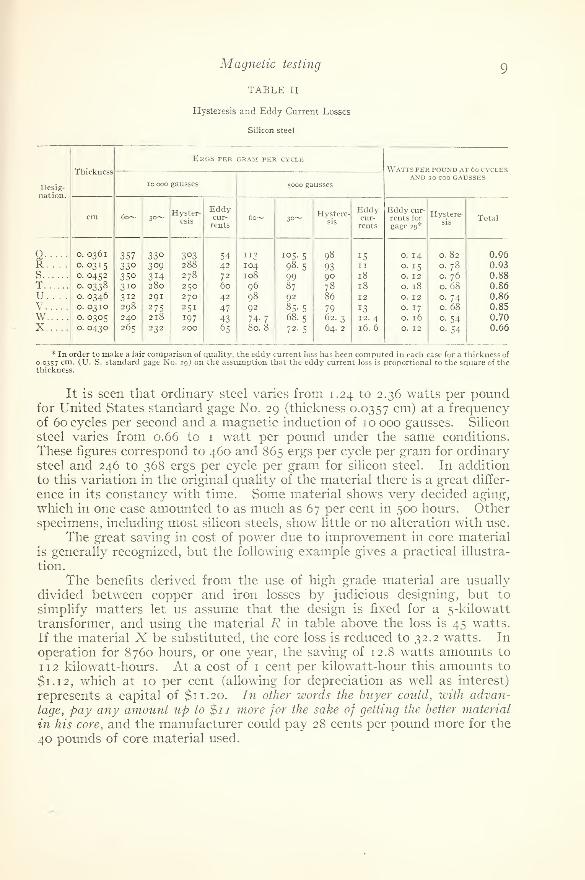
It is seen that ordinary steel varies from 1.24 to 2.36 watts per poundfor United States standard gage No. 29 (thickness 0.0357 cm) at a frequencyof 60 cycles per second and a magnetic induction of 10 000 gausses. Silicon
steel varies from 0.66 to 1 watt per pound under the same conditions.
These figures correspond to 460 and 865 ergs per cycle per gram for ordinarysteel and 246 to 368 ergs per cycle per gram for silicon steel. In addition
to this variation in the original quality of the material there is a great differ-
ence in its constancy with time. Some material shows very decided aging,
which in one case amounted to as much as 67 per cent in 500 hours. Otherspecimens, including most silicon steels, show little or no alteration with use.
The great saving in cost of power due to improvement in core material
is generally recognized, but the following example gives a practical illustra-
tion. .
The benefits derived from the use of high grade material are usually
divided between copper and iron losses by judicious designing, but to
simplify matters let us assume that the design is fixed for a 5-kilowatt
transformer, and using the material R in table above the loss is 45 watts.
If the material X be substituted, the core loss is reduced to 32.2 watts. In
operation for 8760 hours, or one year, the saving of 12.8 watts amounts to
1 12 kilowatt-hours. At a cost of 1 cent per kilowatt-hour this amounts to
$1.12, which at 10 per cent (allowing for depreciation as well as interest)
represents a capital of $11.20. In other words the buyer could, with advan-
tage, pay any amount up to $11 more for the sake of getting the better material
in his core, and the manufacturer could pay 28 cents per pound more for the
40 pounds of core material used.

IO Circular of the Bureau of Standards
If the better silicon steel were to cost 2.8 cents per pound more than
the other (which is improbable),the difference in cost, of the steel would be
$1.12, and the user would each year save 100 per cent of the extra cost.
The comparison between the poorer silicon steel and the ordinary steel
is even more marked. The core loss for material N would be 73 watts, a
difference of 28 watts from R. In a year this would amount to 245 kilowatt-
hours, costing $2.45, thus practically reducing the value of the transformer
by $24.50. Yet the difference in cost of material is only $1.70, if we take
the price of silicon steel delivered at the factory to be 7^ cents per poundand that of ordinary steel to be 3^ cents per pound, and assume 40 poundsto be necessary.
Any frequency from 25 cycles to 90 cycles per second can be used for
the test. When it is desired to determine the eddy current and hysteresis
losses separately, tests at two frequencies (such as 30 and 60 cycles) are
made, from the results of which the two components of the loss can beapproximately calculated.
Any flux densities between 1000 and 14 000 gausses may oe specified.
The flux density stated for any measurement is the average value for all the
material. The deviations from this value in different parts of the steel are
small. The maximum flux <E> is computed from the effective voltage Eio8 E
induced in a secondary winding from the relation <I>= tt- whereJ &4.44 Nn
n = frequency.
N = number of turns in secondary winding.
When so desired, an ammeter is included in the magnetizing circuit, its
reading giving the effective value of the current in the magnetizing coil.
With the aid of the wattmeter and voltmeter readings the wattless compo-nent of the equivalent sine wave can be computed. A curve giving therelation between this quantity and the magnetic induction is for mostpurposes more valuable than a curve showing the permeability, since this
curve indicates the effective value of the current necessary to magnetize,while the permeability indicates the maximum current necessary to mag-netize, to a given value of magnetic induction.
Aging tests are carried on by heating the material in an oven, the usualperiod being two weeks and the temperature between 90° and ioo° C.
Other periods and temperatures can be used when desired. Measurementsof energy loss are made at the beginning and end of this heating, and are
made at two frequencies, in order to determine whether the change is
merely in the hysteresis or also in the electrical conductivity of the material.
The flux density used should have the value which will be applied to thematerial in practice, since the hysteresis changes differently for different
values of flux density, the change usually being greater in the region of
maximum permeability than for the higher flux densities now common in
power transformers.

Magnetic testing
3. TECHNICAL PAPERS ON MAGNETIC WORK.
II
The following papers upon magnetic subjects have been published bythe Bureau. They are issued in pamphlet form and will be sent uponrequest. They may be designated by the numbers which precede the titles
in the list. A complete list of the technical publications of the Bureau, withbrief abstracts of contents, will also be sent upon application.
No. 38. Experiments on Heusler Magnetic Alloys. K. E. Guthe andL. W. Austin.
No. 78. On the Best Method of Demagnetizing Iron in Magnetic Test-ing. C. W. Burrows.
No. 87. Apparatus for the Determination of the Form of a Wave of
Magnetic Flux. M. G. Lloyd and J. V. S. Fisher.
No. 88. Effect of Wave Form upon the Iron Losses in Transformers.M. G. Lloyd.
No. 106. Dependence of Hysteresis upon Wave Form. M. G. Lloyd.No. 108. Errors in Magnetic Testing with Ring Specimens. M. G.
Lloyd.
No. 109. The Testing of Transformer Steel. M. G. Lloyd and J. V. S.
Fisher.
No. 1 1 7. The Determination of the Magnetic Induction in Straight
Bars. C. W. Burrows.
4. REGULATIONS
(a) Application for Test.
—
The request for test of an instrument or
specimen should state explicitly the points at which test is to be made andthe temperature or any other conditions which it is desired should beobserved. Whenever possible, the request should be accompanied by the
fee as shown in the appended schedules.
(b) Identification Marks.—Instruments or specimens and the pack-ages in which they are shipped should both be plainly marked to facilitate
identification, preferably with the name of the shipper, and a special refer-
ence number given to the article and mentioned in the letter requesting the
test.
(c) Shipping Directions.—Instruments should be securely packed in
cases or packages which may be used in returning them to the owner. Topsof cases should be screwed down whenever possible. Transportation charges
are payable by the party desiring the test, and should be prepaid. Instru-
ments and standard bars will be returned by express “collect,” but speci-
mens of material will not be returned unless requested.
(d) Address.—Articles should be addressed simply, “Bureau of
Standards, Washington, D. C.” Delays incident to other forms of address
will thus be avoided. Articles delivered in person or by messenger should
be left at the office of the Bureau and should be accompanied by a written
statement of the test desired.

12 Circular of the Bureau of Standards
(e) Remittances.—Fees may be sent by money order or check
drawn to the order of the “Bureau of Standards.” ' Delays in forwarding
fees will involve corresponding delays in the completion of tests, as certifi-
cates are not issued, nor articles returned, until all fees due thereon havebeen received.
5 . SCHEDULES OF FEES
EFFECTIVE JANUARY 1, 1910
Schedules 90 and 91 are for tests made on specimens of the formindicated in paragraph 2 (b) v.
Schedule 90 .—Short ballistic test
Including normal data of one of the two specimens supplied for the
following inductions: 5000, 10 000, 15 000, 20 000, or any four values pro-
duced by forces under 300 gausses; and hysteresis data for a maximuminduction of 10 000 gausses, giving the residual induction under no mag-netizing force, and the coercive force, or force necessary to reduce the
induction to zero.
(a) Normal induction and permeability $3. 00
( b
)
Hysteresis data 3. 00(c) Normal and hysteresis data 5. 00(d) Curve (extra) 50
If both specimens are to be tested the fee for the second is one-half theabove schedule.
Schedule 91 .—Complete ballistic test.
Including normal data of one of the two specimens supplied, for every2000 gausses up to 20 000, produced by forces under 300 gausses
;and hyster-
esis data for a maximum induction of 10 000 gausses, including the following
ten points of the loop: o, ±2000, ±4000, ±6000, ±8000, and 10000.
(a) Normal induction and permeability $6. 00
( b
)
Hysteresis data 6. 00(c) Normal and hysteresis data 10. 00(d) Curve (extra) 75
Special tests not enumerated above will be charged at reasonable rates.
If both specimens are to be tested, the fee for the second is one-half theabove schedule.
Schedule 92 .
—
Standard bars
These bars, of lengths 25, 30, and 35 cm, are carefully aged and suppliedwith a certificate containing the data of the precision test of schedule 91.
Material. Diameter of section.
Annealed wrought iron (round) o. 95 cm ( inch)Annealed wrought iron (round) 1 . 00 cmAnnealed wrought iron (round) 1. 27 cm inch)Low carbon steel (round) o. 95 cm (-Hs inch)Low carbon steel (round) 1. 00 cmLow carbon steel (round) 1. 27 cm CA inch)

Magnetic testing
ONE BAR(a) Normal data
(b
)
Hysteresis data(c) Normal and hysteresis data
(<d) Standard bars without certificate
13
$7. 007. 00
11. 002. 00
TWO BARS
(
h
) Normal data(i ) Hysteresis data
(j) Normal and hysteresis data
Schedule 93 .—Wattmeter measurements
(a) For test of energy loss at one frequency and one flux density $4. 00
(b ) For each additional flux density. .
(c
)
For each additional frequency 1. 00
(d ) For values of wattless component of magnetizing current (extra) 1. 00
(e
)
When not otherwise specified, test will be made at 30 cycles and 60 cycles for a flux den-sity of 10 000 gausses, fee 5. 00
(ih) Aging test, two weeks at 90-100° C, with repetition of test (a) 8. 00
Special tests not mentioned above will be charged at reasonable rates.
$11. 0011. 0017. 00
Schedule 94.
—
Miscellaneous.
(a) For tests not enumerated above reasonable fees will be charged.
The Bureau will cooperate with manufacturers, scientists, and others
interested in the subjects of methods of measurement, measuring instru-
ments, and physical constants, and will place at the disposal of those inter-
ested such information relative to these subjects as may be in its possession.
The Bureau will also aid in the solution of problems arising in technical
or scientific work, within its scope, and to this end correspondence is invited.
Persons interested in magnetic problems and magnetic measuring instru-
ments and methods are welcome to visit the laboratories of the Bureau,where many of the leading types of apparatus may be seen. Communica-tions should be addressed simply “ Bureau of Standards, Washington, D. C.”
S. W. Stratton,Director.
Approved:Benj. S. CabtE,
Acting Secretary.
o
