circular connectors in stock versions signal and · pdf filein stock versions signal and...
TRANSCRIPT

In Stock VersionsSignal and Universal
Circular Connectors

Coninvers is an autonomouscompany and is the
specialist for circularconnectors within the PhoenixContact Group. We develop,design and manufacture ourproducts on the site of thecompany headquarters inHerrenberg, south of Stuttgart.
Distribution is carried outworldwide through our ownsales partners and throughPhoenix Contact salescompanies. In the USA, we arerepresented by our ownsubsidiary – RDE Connectors& Cables, Florida.
Coninvers – Connectors for Industrial Automation
The high quality of our products andservices is the basis for our successful
business operations.
Coninvers management tasks have beendocumented in accordance with DIN EN
ISO 9001:2000 since 1995.
Connectors with a system
The advantage of our signal connector system is itsmodular design. It allows us to offer our customers a widerange of model variants and combinations, and to deliverthese within three working days.
Coninvers headquarters in Herrenberg

3Signal / Universal • Edition 03/04 Coninvers
Contents
Coninvers Catalogs
Overview
Coninvers Circular ConnectorsSignal and Universal
Tools and Accessoriesfor Signal Connectors
Ordering Information
Appendix
Page
The Complete Range at a Glance 5
Coninvers Circular Connectors 6-7
General Information 8-9
M23 Signal Connectors, Product Selection 10-11
M23 Signal Connectors, RC / UC Series 12-25
Bayonet Signal Connectors, Product Selection 26-27
Bayonet Signal Connectors, TU Series 28-33
Contact Inserts, 6 to 19-Position 34-39
40-41
42
Technical Terms 43
Index of Order Numbers 44-46

4 Signal / Universal • Edition 03/04Coninvers
5Signal / Universal • Edition 03/04 Coninvers
VorzugstypenAntriebstechnik
Rundsteckverbinder
CO
NIN
VER
S®
Gesamtkatalog
SignalsteckverbinderSensor-Aktor-Steckverbinder
Ausgabe 04/2003
KompetenzzentrumIndustrieverkabelung
CO
NIN
VER
S®
Wir schaffen Verbindungen
CreatingConnections
VorzugstypenSignal und Universal
Rundsteckverbinder
ProduktübersichtSignalsteckverbinder – Schnellauswahl
• M23 Verriegelung
• Bajonett Verriegelung
Ausgabe 02/03
CO
NIN
VER
S®
Coninvers – The Complete Range at a Glance
In Stock VersionsCircular ConnectorsDrive Applications
Available in:GermanEnglishFrenchItalian
Competence CenterIndustrial Cabling
Available in:German
ConinversCompany Brochure
Available in:GermanEnglish
Complete CatalogSignal ConnectorsSensor/ActuatorConnectors
Available in:GermanEnglish
In Stock VersionsCircular ConnectorsSignal and Universal
Available in:GermanEnglishFrenchItalian
Quick SelectionGuideSignal ConnectorsProduct Overview
Available in:GermanEnglish
Coninvers catalogson one CD-ROM
6 Signal / Universal • Edition 03/04Coninvers
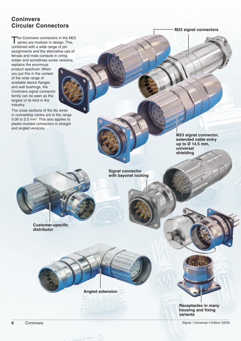
ConinversCircular Connectors
The Coninvers connectors in the M23series are modular in design. This,
combined with a wide range of pinassignments and the alternative use offemale and male contacts in crimp,solder and sometimes screw versions,explains the enormousproduct spectrum. Whenyou put this in the contextof the wide range ofavailable device flangesand wall bushings, theConinvers signal connectorfamily can be seen as thelargest of its kind in theindustry.
The cross sections of the litz wiresin connecting cables are in the range0.08 to 2.5 mm2. This also applies toplastic-molded connectors in straightand angled versions.
M23 signal connector,extended cable entryup to Ø 14.5 mm,universal shielding
M23 signal connectors
Signal connectorwith bayonet locking
Customer-specificdistributor
Angled extension
Receptacles in manyhousing and fixing variants

7Signal / Universal • Edition 03/04 Coninvers
New power connectorsConPower P30 / P70
The ConPower power connector familycomprises two performance classes:P30 up to 30 A with M23 screw locking andP70 up to 70 A with M40 screw locking.The clamping range for shielded cablesincludes diameters from 7.5 mm to 25 mm.
Male and female contacts cover crimpranges from 0.08 mm2 to 16 mm2.
Extremely simple and time-saving handlingduring assembly makes the angled panelmounting connectors (equipment flanges)particularly attractive. The male contactscan be clipped into theinsulating body fromthe side, forexample, thehousing is madeup of two parts,and the cable exitdirection can beadjusted infinitelyin a range of 310degrees.A robust, metalrotatingmechanismensures a highdegree of operationalsafety and reliable EMC protectionover a wide temperature range,even in the case of frequentadjustments.
M23 power connectors Connection cross section up to 4 mm2
M40 power connectors Connection cross section up to 16 mm2
M16 plastic-molded receptacles with solder connection
M16 circular connectors permit a highdensity of positions in a small amount ofspace. The preassembled and moldedconnecting cables are available with 8, 10,12 and 14 to 19 positions, e.g. as a centralconnector connection for distributorsystems.
M16 connectors are molded with proven,rugged PUR housing material and fulfill therequirements of IP67 protection.
Coninvers offers suitable receptacles inmale versions for front or rear screwmounting with a solder connection.
Plastic-molded signal connectors
M16 receptacles with up to 19 positions
Plastic-molded M16 connectors with up to 19 positions

8 Signal / Universal • Edition 03/04Coninvers
Coninvers – Circular ConnectorsSignal and Universal
The Coninvers circular connector range has an M23 locking thread which has beendeveloped for industrial applications.Coninvers also offers a variant with abayonet quick locking system.The M23/bayonet signal circular connectorsin the RC/UC/TU series are available withcrimp, screw and solder connectionsystems, as well as for PCB mounting.Signal connectors in the UC series, alsowith M23 locking, feature an extendedcable entry range and universal EMCshielding.Signal connectors in the TU series arebased on UC connectors but feature abayonet quick locking system.The individual connector is put togetherfrom a defined number of articles for thethree components:– Housing, consisting of an M23 knurled
cap or bayonet, an inside sleeve, ahinged insulation sleeve and an adaptercap.
– Cable gland, including the seal, the strainrelief and the optional shielded connection.
– Contact insert, comprising the contactcarrier and the contacts.
Circular connectors are supplied asindividual components.
Signal circular connectors
Signal circular connectorswith universal shielding
The signal circular connectors in the RCseries are available as 6 to 19-positionversions in crimp, screw and solderconnection types, as well as for PCBconnection (dip solder).Unshielded connectors fulfill therequirements of IP65/ IP68 protection,depending on the cable gland used. Thecomponents for the connection of shieldedconductors offer IP67 protection as a resultof the special cable gland.The product chart on page 10 shows howthe required connector is put together andhow the individual components arecombined.Circular connectors are supplied asindividual components (from stock).
Like the RC series, the signal circularconnectors in the UC series are completelymodular in design. This means that a widevariety of connectors can be created from asmall number of different components.Both series contain M23 connectors withsimilar technical specifications. The UCseries uses the same insulating bodies inall pin assignment variants. The differenceis that the UC series is larger than the RCseries, i.e. it offers more cabling space andcan accommodate larger cable diameters.Unlike the RC series, the shielding functionand the cable clamping are universal. It isnot necessary to adapt the shieldingelements to the cables used. This facilitateshandling in the field.
9Signal / Universal • Edition 03/04 Coninvers
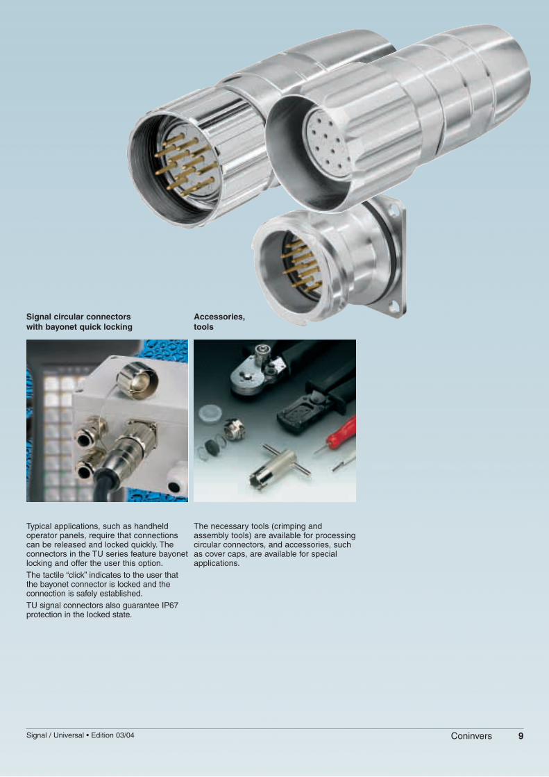
Signal circular connectorswith bayonet quick locking
Accessories,tools
Typical applications, such as handheldoperator panels, require that connectionscan be released and locked quickly. Theconnectors in the TU series feature bayonetlocking and offer the user this option.The tactile “click” indicates to the user thatthe bayonet connector is locked and theconnection is safely established.TU signal connectors also guarantee IP67protection in the locked state.
The necessary tools (crimping andassembly tools) are available for processingcircular connectors, and accessories, suchas cover caps, are available for specialapplications.

10 Signal / Universal • Edition 03/04Coninvers
M23 • RC Series / UC SeriesSignal Circular ConnectorsProduct Selection
CombinationsThe product chart show the possiblecombinations of sleeve housing andconnecting housing or panel mountingbase.
The chart differentiates between shieldedand unshielded connectors.
Selection of connectorsThe modular system allows the individualconnector to be selected from a definednumber of articles. To specify a connectorfor the device and mounting side, the
housing is supplemented by thecorresponding cable gland and contactinsert, including the contacts.
HousingShielded sleeve housings, page 14
Shielded connecting housings, page 14
Shielded connecting housings for wall mounting
TGGM TGGMK TGGK TWGM
KGGM KGGK KGGMK
AAGG AIGG AIGZ
Front mounting, page 18 Rear mounting, page 19
Sleeve housings with universal shielding, page 16
TGGUM TWGUM
Connecting housings with universal shielding, page 17
KGGUM KGGUZ
Rear mounting
Connecting housings for wall mountingwith universal shielding, page 17
Unshielded sleeve housings, page 15
TGUM... TWUM...
Unshielded connecting housings, page 15
KGUM...
Panel mounting bases
AAGR
Shielded front mounting, page 18
AALZ
AAWF
AILB
Shielded rear mounting, page 19
AILG
AISZ AISG
AAGF
Unshielded front mounting, page 18
Housing type AAWF cannot becombined with dip soldercontacts or 19-pos. crimp.
Shielded
Shielded
Shielded
With universal shielding
With universal shielding
Shielded
Unshielded
Unshielded
11Signal / Universal • Edition 03/04 Coninvers
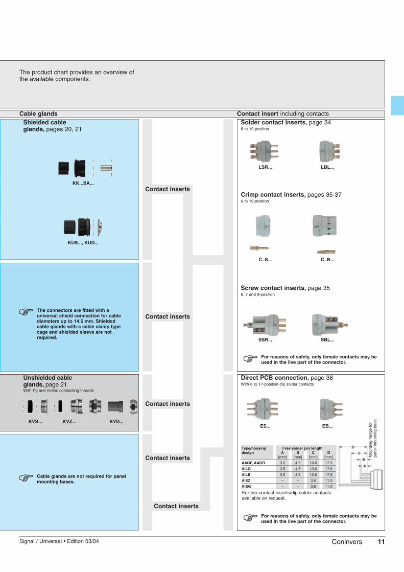
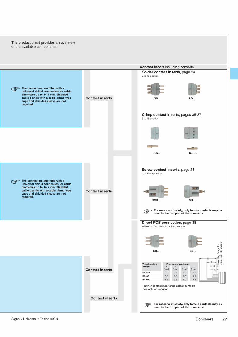
The product chart provides an overview ofthe available components.
Cable glands Contact insert including contactsShielded cableglands, pages 20, 21
KK...SA...
The connectors are fitted with auniversal shield connection for cablediameters up to 14.5 mm. Shieldedcable glands with a cable clamp typecage and shielded sleeve are notrequired.
Unshielded cable glands, page 21With Pg and metric connecting threads
KVS... KVZ... KVD...
Cable glands are not required for panelmounting bases.
Solder contact inserts, page 346 to 19-position
Crimp contact inserts, pages 35-376 to 19-position
Screw contact inserts, page 356, 7 and 9-position
Direct PCB connection, page 38With 6 to 17-position dip solder contacts
Contact inserts
Contact inserts
Contact inserts
Contact inserts
Contact inserts
LSR... LBL...
C..S... C..B...
SSR... SBL...
ES... EB...
Further contact inserts/dip solder contactsavailable on request.
Type/housing Free solder pin lengthdesign A B C D
[mm] [mm] [mm] [mm]
AAGF, AAGR 3.5 4.5 10.0 17.5
AILG 3.5 4.5 10.0 17.5
AILB 3.5 4.5 10.0 17.5
AISZ – – 3.5 11.0
AISG – – 3.5 11.0
Mou
ntin
g fla
nge
for
pane
l mou
ntin
g ba
se
For reasons of safety, only female contacts may beused in the live part of the connector.
For reasons of safety, only female contacts may beused in the live part of the connector.
KUS..., KUD...

12 Signal / Universal • Edition 03/04Coninvers
M23 • RC Series / UC SeriesTechnical Data
Mechanical data:Housing material: Machined component: copper-zinc alloy (CuZn), die-cast part: zinc (GD-Zn);
types TGGK/KGGK: plastic part: thermoplastic polymers (PET), polycarbonate (PC)/UL 94 V0, largely halogen-free, die-cast part: zinc (GD-Zn), union nut: CuZn
Housing surface: Nickel-plated (standard), black, chrome on request, plastic sheath;types TGGK/KGGK: die-cast part: passivated (Cr), union nut: nickel-plated (Ni)
Insulating body: Thermoplastic polyester (PBT), polyamide (PA 66), polycarbonate (PC); storage at 15-35 °C, 40-70 % rel. humidityInflammability: UL 94 V0
Contact material: Copper-zinc alloy (CuZn)
Contact surface: Nickel-plated (Ni) with gold layer (Au) and passivated
Contact connection type: Solder cup, crimp and screw versions, dip solder pin
Gasket and O-ring: Fluorine rubber (FPM); types TGGK/KGGK: perbunane (NBR) gasket
Flat gasket: Perbunane (NBR with fabric insert) fluorine rubber (FPM)
Temperature range: -40°C/+125°C (long-term temperature)
Conductor entry: EMC design for external cable diameters 2 - 10.5 mm, without EMC protection for cable diameters 4 - 14 mmEMC design with extended cable entry range (UC series) for external cable diameters 2 - 14.5 mm
Locking method: M23 screw locking
Mechanical insertion/withdrawal cycles: Standard: 50, more on request
Degree of protection: EMC version: IP67 in the locked state; without EMC protection: IP65 - IP68 (depending on the cable gland)
Certification: UL-recognized File No 153698 (M) Underwriters Laboratories Inc.® (not for types TGGK/KGGK or the UC series)
Electrical data:
Number of positions 6, 7 9(8+1) 9(6+3) 12 16 17 19(16+3)
Contacts 6, 7 8 + 1 6 + 3 11, 12 15, 16 16, 17 16 + 3Contact Ø [mm] 2 1 2 1 2 1 1 1 1 1,5Conductor Solder connection contacts x [mm2] 6 (7) x 2.5 8x1.0+1x2.5 6x1.0+3x2.5 12 x 2.5 16 x 1.0 17 x 1.0 16 x 1.0 + 3 x 1.0cross section Crimp connection contacts x [mm2] 6 (7) x 2.5 8x0.56+1x2.5 12 x 0.56 16 x 0.56 17 x 0.56 16x1.0+3x1.5Nominal/rated current [A] 20 8 20 8 20 8 8 8 8 10Nominal/rated voltage [V] 300 300 150 150 150 150 150Test voltage [kV AC] 2.5 2.5 1.5 1.5 1.5 1.5 1.5Surge voltage category 1) II II II II II II IIInsulation resistance [Ω] ≥1016 ≥1016 ≥1012 ≥1012 ≥1012 ≥1012 ≥1012
Contact resistance [mΩ] ≤3 ≤3 ≤3 ≤3 ≤3 ≤3 ≤3Contamination class in acc. with IEC 664-1 2 (31) 2 (31) 2 (31) 2 (31) 2 (31) 2 (31) 2 (31)
1) Reference: DIN EN 61984:2001 (see also appendix of technical terms, page 43).
Derating curve 12-position cable and sleeve connectors
Temperature [°C]
Cur
rent
[A
]
Shield attenuation curve for RC seriesBased on DIN 47250-6/01.83
Frequency [MHz]
Atte
nuat
ion
[dB
]
Shield attenuation curve for UC series (universal shielding)Based on DIN 47250-6/01.83
Frequency [MHz]
Atte
nuat
ion
[dB
]

13Signal / Universal • Edition 03/04 Coninvers
M23 • RC Series / UC SeriesPin Assignments and Coding
Number of positions
6-position
Solder / crimp / screwPages 34 - 39
7-position
Solder / crimp / screwPages 34 - 39
9-position(6+3)Solder
Pages 34, 38
9-position(8+1)
Solder / crimp / screwPages 34 - 39
12-position
Solder / crimpPages 34 - 39
16-position
SolderPages 34, 38
16-position
CrimpPages 35 - 37
17-position
SolderPages 34, 38
17-position
CrimpPages 35 - 37
19-position(16+3)
Solder / crimpPages 34 -37
Clockwise
Male
Counter-clockwise
Female
Counter-clockwise
Male
Clockwise
Female
Contact chamber numbering(view of plug-in side)
Other coding versions can be configured manually or mechanically on request.
Direction of contact chamber numbering(view of plug-in side)
Male, clockwise(standard)
Male, counter-clockwise(opposite direction)
Female, counter-clockwise(standard)
Female, clockwise(opposite direction)
14 Signal / Universal • Edition 03/04Coninvers
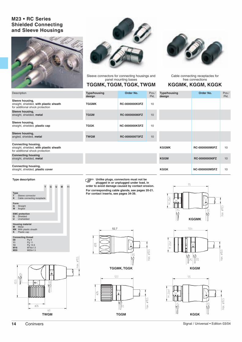
M23 • RC SeriesShielded Connectingand Sleeve Housings
Sleeve connectors for connecting housings andpanel mounting bases
TGGMK, TGGM, TGGK, TWGM
Cable connecting receptacles for free connections
KGGMK, KGGM, KGGK
Description
Sleeve housing,straight, shielded, with plastic sheathfor additional shock protection
Sleeve housing,straight, shielded, metal
Sleeve housing,straight, shielded, plastic cap
Sleeve housing,angled, shielded, metal
Connecting housing,straight, shielded, with plastic sheath for additional shock protection
Connecting housingstraight, shielded, metal
Connecting housing,straight, shielded, plastic cover
Type/housing Order No. Pcs./design Pkt.
TGGMK RC-0000000K0FZ 10
TGGM RC-000000080FZ 10
TGGK NC-0000000KSFZ 10
TWGM RC-0000000T0FZ 10
Type/housing Order No. Pcs./design Pkt.
KGGMK RC-0000000M0FZ 10
KGGM RC-000000090FZ 10
KGGK NC-0000000MSFZ 10
Unlike plugs, connectors must not beplugged in or unplugged under load, in
order to avoid damage caused by contact erosion.
For corresponding cable glands, see pages 20-21.For contact inserts, see pages 34-39.
TWGM KGGKTGGM
TGGMK, TGGK KGGM
KGGMK
Type description
T G U M 11
TypeT Sleeve connectorK Cable connecting receptacle
FormG StraightW Angled
EMC protectionG ShieldedU Unshielded
Housing materialM MetalMK With plastic sheathK Plastic cap
Connecting thread09 Pg 911 Pg 1113 Pg 13.5M16 M16x1.5M20 M20x1.5
15Signal / Universal • Edition 03/04 Coninvers
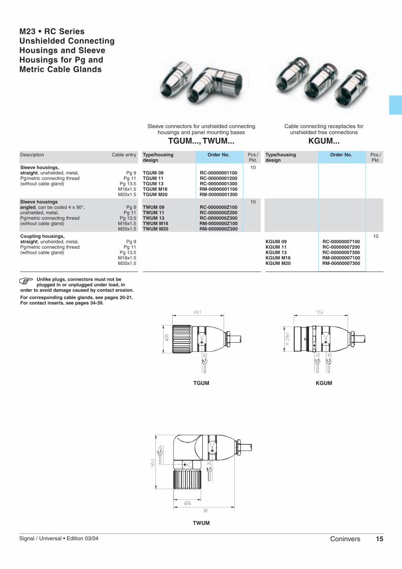
M23 • RC SeriesUnshielded ConnectingHousings and SleeveHousings for Pg andMetric Cable Glands
Sleeve connectors for unshielded connectinghousings and panel mounting bases
TGUM..., TWUM...
Cable connecting receptacles for unshielded free connections
KGUM...
Description Cable entry
Sleeve housings,straight, unshielded, metal, Pg 9Pg/metric connecting thread Pg 11(without cable gland) Pg 13.5
M16x1.5M20x1.5
Sleeve housingsangled, can be coded 4 x 90°, Pg 9unshielded, metal, Pg 11Pg/metric connecting thread Pg 13.5(without cable gland) M16x1.5
M20x1.5
Coupling housings,straight, unshielded, metal, Pg 9Pg/metric connecting thread Pg 11(without cable gland) Pg 13.5
M16x1.5M20x1.5
Type/housing Order No. Pcs./design Pkt.
10TGUM 09 RC-00000001100TGUM 11 RC-00000001200TGUM 13 RC-00000001300TGUM M16 RM-00000001100TGUM M20 RM-00000001300
10TWUM 09 RC-0000000Z100TWUM 11 RC-0000000Z200TWUM 13 RC-0000000Z300TWUM M16 RM-0000000Z100TWUM M20 RM-0000000Z300
Type/housing Order No. Pcs./design Pkt.
10KGUM 09 RC-00000007100KGUM 11 RC-00000007200KGUM 13 RC-00000007300KGUM M16 RM-00000007100KGUM M20 RM-00000007300
Unlike plugs, connectors must not beplugged in or unplugged under load, in
order to avoid damage caused by contact erosion.
For corresponding cable glands, see pages 20-21.For contact inserts, see pages 34-39.
TWUM
TGUM KGUM
16 Signal / Universal • Edition 03/04Coninvers
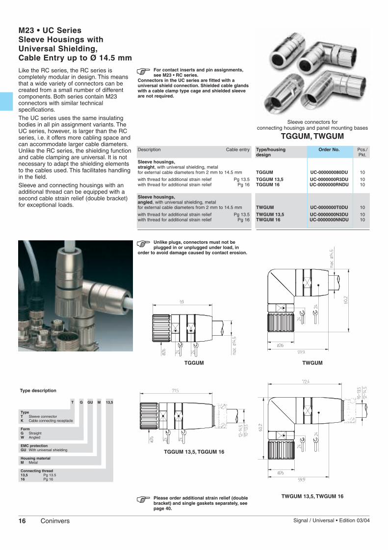
M23 • UC SeriesSleeve Housings withUniversal Shielding,Cable Entry up to Ø 14.5 mm
Sleeve connectors for connecting housings and panel mounting bases
TGGUM, TWGUM
Description Cable entry
Sleeve housings,straight, with universal shielding, metal for external cable diameters from 2 mm to 14.5 mm
with thread for additional strain relief Pg 13.5with thread for additional strain relief Pg 16
Sleeve housings,angled, with universal shielding, metal for external cable diameters from 2 mm to 14.5 mm
with thread for additional strain relief Pg 13.5with thread for additional strain relief Pg 16
Type/housing Order No. Pcs./design Pkt.
TGGUM UC-000000080DU 10
TGGUM 13,5 UC-0000000R3DU 10TGGUM 16 UC-0000000RNDU 10
TWGUM UC-0000000T0DU 10
TWGUM 13,5 UC-0000000N3DU 10TWGUM 16 UC-0000000NNDU 10
Unlike plugs, connectors must not beplugged in or unplugged under load, in
order to avoid damage caused by contact erosion.
TWGUMTGGUM
Like the RC series, the RC series iscompletely modular in design. This meansthat a wide variety of connectors can becreated from a small number of differentcomponents. Both series contain M23connectors with similar technicalspecifications.The UC series uses the same insulatingbodies in all pin assignment variants. TheUC series, however, is larger than the RCseries, i.e. it offers more cabling space andcan accommodate larger cable diameters.Unlike the RC series, the shielding functionand cable clamping are universal. It is notnecessary to adapt the shielding elementsto the cables used. This facilitates handlingin the field.Sleeve and connecting housings with anadditional thread can be equipped with asecond cable strain relief (double bracket)for exceptional loads.
For contact inserts and pin assignments,see M23 • RC series.
Connectors in the UC series are fitted with auniversal shield connection. Shielded cable glandswith a cable clamp type cage and shielded sleeveare not required.
Type description
T G GU M 13,5
TypeT Sleeve connectorK Cable connecting receptacle
FormG StraightW Angled
EMC protectionGU With universal shielding
Housing materialM Metal
Connecting thread13,5 Pg 13.516 Pg 16
Please order additional strain relief (doublebracket) and single gaskets separately, seepage 40.
TGGUM 13,5, TGGUM 16
TWGUM 13,5, TWGUM 16
17Signal / Universal • Edition 03/04 Coninvers
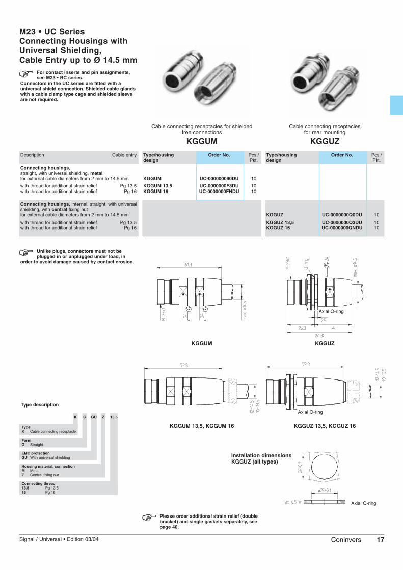
M23 • UC SeriesConnecting Housings withUniversal Shielding,Cable Entry up to Ø 14.5 mm
Cable connecting receptacles for shielded free connections
KGGUM
Cable connecting receptacles for rear mounting
KGGUZ
Unlike plugs, connectors must not beplugged in or unplugged under load, in
order to avoid damage caused by contact erosion.
KGGUM KGGUZ
Description Cable entry
Connecting housings,straight, with universal shielding, metalfor external cable diameters from 2 mm to 14.5 mm
with thread for additional strain relief Pg 13.5with thread for additional strain relief Pg 16
Connecting housings, internal, straight, with universalshielding, with central fixing nut for external cable diameters from 2 mm to 14.5 mm
with thread for additional strain relief Pg 13.5with thread for additional strain relief Pg 16
Type/housing Order No. Pcs./design Pkt.
KGGUM UC-000000090DU 10
KGGUM 13,5 UC-0000000F3DU 10KGGUM 16 UC-0000000FNDU 10
Type/housing Order No. Pcs./design Pkt.
KGGUZ UC-0000000Q0DU 10
KGGUZ 13,5 UC-0000000Q3DU 10KGGUZ 16 UC-0000000QNDU 10
For contact inserts and pin assignments,see M23 • RC series.
Connectors in the UC series are fitted with auniversal shield connection. Shielded cable glandswith a cable clamp type cage and shielded sleeveare not required.
Axial O-ring
Type description
K G GU Z 13,5
TypeK Cable connecting receptacle
FormG Straight
EMC protectionGU With universal shielding
Housing material, connectionM MetalZ Central fixing nut
Connecting thread13,5 Pg 13.516 Pg 16
Installation dimensions KGGUZ (all types)
Axial O-ring
KGGUM 13,5, KGGUM 16 KGGUZ 13,5, KGGUZ 16
Please order additional strain relief (doublebracket) and single gaskets separately, seepage 40.
Axial O-ring

18 Signal / Universal • Edition 03/04Coninvers
M23 • RC SeriesPanel Mounting BasesFront Mounting
Panel mounting bases for front mounting
AAGF, AAGR, AALZ, AAWF
Cable connecting receptacles for front mounting
AAGG
Description Wall thickness[mm]
Panel mounting base,external, straight, flat gasket(self-adhesive), 4-hole mounting, for connecting unshielded cable connectors from 1
Panel mounting base,external, straight, radial O-ring, 4-hole mounting, with reinforced mounting flange, for shielded applications from 3
Panel mounting base,external, straight, central fixing nut, for shielded applications 1-4.5
Panel mounting base,external, angled, flat gasket, 4-hole mounting, for feeding a shielded cable into a wall from 1
Panel mounting base,external, straight, shielded, 4-hole mounting and O-ring, for wall bushing for a shielded cable 3-7
Type/housing Order No. Pcs./design Pkt.
AAGF RC-00000002200 10
AAGR RC-0000000WQ00 10
AALZ RC-00000006100 10
AAWF RC-0000000A000 10
Type/housing Order No. Pcs./design Pkt.
AAGG RC-0000000B2FZ 10
For shielded cable glands, see page 20-21
Housing type AAWF cannot be combinedwith dip solder contacts or 19-pos. crimp.
Installation dimensions AAGF, AAGR,AAWF, AAGG
AAGGAALZ
AAGR
AAWF
AAGF
In the case of frontmounting, the panelmounting base is fitted tothe device from outsideusing screws, nuts orthreads.The contact insert thenestablishes theconnection to the deviceby either solder or crimpconnections at the deviceend.
Type descriptionA A G F
TypeA Panel mounting base
Installation methodA Front mounting I Rear mounting
FormG StraightL Light versionS Heavy versionW Angled
ConnectionF Flat gasketR Radial gasket (O-ring)Z Central fixing nutG Threaded flangeB Drilling flange
Axial O-ring/Flat gasket
Radial O-ring
Radial O-ring
Radial O-ring
Flat gasketFlat gasket
Axial O-ring
19Signal / Universal • Edition 03/04 Coninvers
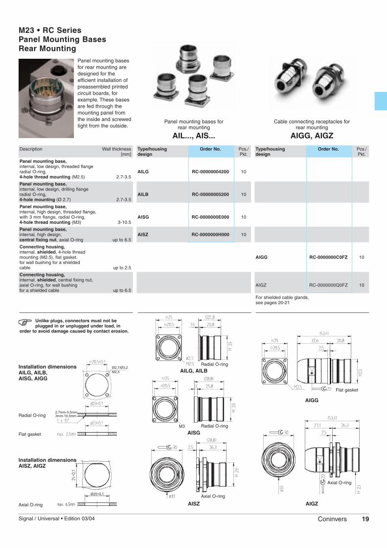
M23 • RC SeriesPanel Mounting BasesRear Mounting
Panel mounting bases for rear mounting
AIL..., AIS...
Cable connecting receptacles for rear mounting
AIGG, AIGZ
Type/housing Order No. Pcs./design Pkt.
AILG RC-00000004200 10
AILB RC-00000005200 10
AISG RC-0000000E000 10
AISZ RC-0000000H000 10
Type/housing Order No. Pcs./design Pkt.
AIGG RC-0000000C0FZ 10
AIGZ RC-0000000Q0FZ 10
For shielded cable glands, see pages 20-21
Unlike plugs, connectors must not beplugged in or unplugged under load, in
order to avoid damage caused by contact erosion.
Installation dimensions AISZ, AIGZ
AIGZAISZ
AISG
AIGG
AILG, AILB
Panel mounting basesfor rear mounting aredesigned for theefficient installation ofpreassembled printedcircuit boards, forexample. These basesare fed through themounting panel fromthe inside and screwedtight from the outside.
Description Wall thickness[mm]
Panel mounting base,internal, low design, threaded flangeradial O-ring, 4-hole thread mounting (M2.5) 2.7-3.5
Panel mounting base,internal, low design, drilling flangeradial O-ring, 4-hole mounting (Ø 2.7) 2.7-3.5
Panel mounting base,internal, high design, threaded flange,with 3 mm flange, radial O-ring, 4-hole thread mounting (M3) 3-10.5
Panel mounting base,internal, high design, central fixing nut, axial O-ring up to 6.5
Connecting housing,internal, shielded, 4-hole thread mounting (M2.5), flat gasket, for wall bushing for a shieldedcable up to 2.5
Connecting housing,internal, shielded, central fixing nut, axial O-ring, for wall bushing for a shielded cable up to 6.5
Installation dimensions AILG, AILB,AISG, AIGG
Radial O-ring
Flat gasket
Axial O-ring
Axial O-ring
Axial O-ring
Radial O-ring
Radial O-ring
Flat gasket
20 Signal / Universal • Edition 03/04Coninvers
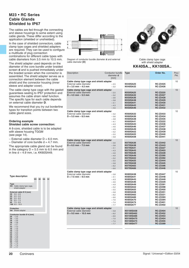
M23 • RC SeriesCable Glands Shielded to IP67
Cable clamp type cagewith shield adapter
KK40SA.., KK100SA..
Description Conductor bundlediameter d
[mm]
Cable clamp type cage and shield adapterExternal cable diameter ≈ 2.5D = 3.5 mm – 4.5 mm ≈ 3.2
Cable clamp type cage and shield adapterExternal cable diameter ≈ 2.5D = 4.5 mm – 5.5 mm ≈ 3.2
≈ 3.6≈ 3.8≈ 4.1≈ 4.3≈ 4.6
Cable clamp type cage and shield adapterExternal cable diameter ≈ 3.2D = 5.5 mm – 6.5 mm ≈ 3.6
≈ 3.8≈ 4,1≈ 4.3≈ 4.6≈ 4.9≈ 5.2 ≈ 5.5≈ 5.8
Cable clamp type cage and shield adapterExternal cable diameter ≈ 3.6D = 6.5 mm – 7.5 mm ≈ 3.8
≈ 4.1≈ 4.3≈ 4.6≈ 4.9≈ 5.2 ≈ 5.5≈ 5.8≈ 6.2≈ 6.6
Cable clamp type cage and shield adapterExternal cable diameter ≈ 3.8D = 7.5 mm – 9.5 mm ≈ 4.1
≈ 4.3≈ 4.6≈ 4.9≈ 5.2≈ 5.5≈ 5.8≈ 6.2≈ 6.6≈ 7.0≈ 7.4≈ 7.7
Cable clamp type cage and shield adapterExternal cable diameter ≈ 5.8D = 9.5 mm – 10.5 mm ≈ 6.2
≈ 6.6≈ 7.0≈ 7.4≈ 7.7
Type Order No. Pcs./Pkt.
10KK40SA25 RC-Z2425KK40SA32 RC-Z2426
10KK50SA25 RC-Z2225KK50SA32 RC-Z2427KK50SA36 RC-Z2428KK50SA38 RC-Z2429KK50SA41 RC-Z2430KK50SA43 RC-Z2431KK50SA46 RC-Z2432
10KK60SA32 RC-Z2433KK60SA36 RC-Z2434KK60SA38 RC-Z2435KK60SA41 RC-Z2222KK60SA43 RC-Z2436KK60SA46 RC-Z2437KK60SA49 RC-Z2438KK60SA52 RC-Z2439KK60SA55 RC-Z2440KK60SA58 RC-Z2441
10KK70SA36 RC-Z2442KK70SA38 RC-Z2443KK70SA41 RC-Z2227KK70SA43 RC-Z2403KK70SA46 RC-Z2228KK70SA49 RC-Z2395KK70SA52 RC-Z2392KK70SA55 RC-Z2444KK70SA58 RC-Z2445KK70SA62 RC-Z2396KK70SA66 RC-Z2446
10KK85SA38 RC-Z2447KK85SA41 RC-Z2448KK85SA43 RC-Z2449KK85SA46 RC-Z2229KK85SA49 RC-Z2391KK85SA52 RC-Z2398KK85SA55 RC-Z2450KK85SA58 RC-Z2451KK85SA62 RC-Z2221KK85SA66 RC-Z2393KK85SA70 RC-Z2394KK85SA74 RC-Z2401KK85SA77 RC-Z2402
10KK100SA58 RC-Z2404KK100SA62 RC-Z2452KK100SA66 RC-Z2453KK100SA70 RC-Z2454KK100SA74 RC-Z2455KK100SA77 RC-Z2399
Diagram of conductor bundle diameter d and externalcable diameter [D]
The cables are fed through the connectingand sleeve housings to some extent usingcable glands. These differ according to theapplication (shielded or unshielded).In the case of shielded connectors, cableclamp type cages and shielded adaptersare required. They can be used to configurea multitude of plug connectioncombinations for different cable types withcable diameters from 3.5 mm to 10.5 mm.The shield adapter used depends on thediameter of the core bundle under braidedscreen d and is pushed immediately underthe braided screen when the connector isassembled. The shield adapter serves as aconnection element between the cableshield and the connector housing (innersleeve and adapter cover).The cable clamp type cage with the gasketguarantees sealing to IP67 protection andassumes the cable strain relief function.The specific type for each cable dependson external cable diameter D.We recommend that you try out borderlinetypes for transition points between twocable gland sizes.
Ordering exampleShielded cable screw connection:A 6-core, shielded cable is to be adaptedwith sleeve housing TGGM (see page 14).– External cable diameter D = 6.0 mm.– Diameter of core bundle d = 4.7 mm.The appropriate cable gland can be foundin the category D = 5.5 mm to 6.5 mm andin line d ≈ 4.9 mm, i.e. KK60SA49.
Type descriptionKK 85 SA 52
TypeKK Cable clamp type cage,
shield adapter
External cable Ø D [mm]40 3.5 - 4.5 50 4.5 - 5.560 5.5 - 6.570 6.5 - 7.585 7.5 - 9.5100 9.5 - 10.5
ProtectionSA Shield adapter
Conductor bundle Ø d [mm]25 ≈ 2.532 ≈ 3.236 ≈ 3.638 ≈ 3.841 ≈ 4.143 ≈ 4.346 ≈ 4.649 ≈ 4.952 ≈ 5.255 ≈ 5.558 ≈ 5.862 ≈ 6.266 ≈ 6.670 ≈ 7.074 ≈ 7.477 ≈ 7.7

21Signal / Universal • Edition 03/04 Coninvers
M23 • RC SeriesCable Glands Shielded / Unshielded
Cable glands withPg/metric threads
KVS..., KVZ..., KVD...
Description Conductor Cableentry Ø D
[mm]
Cable gland forunshielded applications Pg 9 6 – 10in acc. with DIN 46 320, IP65 Pg 11 8 – 12
Pg 13.5 10 – 14
M16x1.5 3 – 10M20x1.5 4 – 14
Cable gland withdouble bracket cable strain Pg 9 6 – 10relief, for unshielded Pg 11 8 – 12applications, IP65 Pg 13.5 10 – 14
M16x1.5 3 – 10M20x1.5 4 – 14
IP68 cable gland for unshielded Pg 9 6.5 – 9applications Pg 11 7 – 10.5with PVC gasket sleeve Pg 13.5 9 – 13
M16x1.5 6.5 – 9M20x1.5 9 – 13
Type Order No. Pcs./Pkt.
10KVS 09 RC-Z2091KVS 11 RC-Z2092KVS 13 RC-Z2093
KVS M16 RC-Z2406KVS M20 RC-Z2409
10KVZ 09 RC-Z2051KVZ 11 RC-Z2052KVZ 13 RC-Z2053
KVZ M16 RC-Z2407KVZ M20 RC-Z2410
10KVD 09 RC-Z2191KVD 11 RC-Z2196KVD 13 RC-Z2202
KVD M16 RC-Z2414KVD M20 RC-Z2417
Various cable glands can be supplied withPg and metric threads for unshieldedconnectors. These are screwed into theadapter cover from the outside. Suitablevariants are available for external cablediameters from 3 mm to 14 mm.
Ordering exampleUnshielded cable gland:A 9-core, unshielded cable is to be adaptedwith coupling housing KGUM09 (see page 15).– External cable diameter D = 8 mm.If a Pg cable gland in acc. with DIN 46 320is to be selected, type KVS 09corresponding to PG 9 for external cablediameters from 6 mm to 10 mm optimallyfulfills the requirements.
The cable entry of the connecting andsleeve housings must correspond to thecable glands.
Type descriptionKV D 11
TypeKV Cable gland,
unshielded
Unshielded version S Standard (IP65)Z Double bracket
strain relief (IP65)D Increased sealing (IP68)
Cable entry09 Pg 9 11 Pg 11 13 Pg 13.5 M16 M16x1.5 M20 M20x1.5
Universal cable glands KUS... (shielded)and KUD... (unshielded) are available asalternatives to the shielded cable glands toIP67 for applications with less stringentrequirements regarding shield attenuation.Irrespective of the diameter of the cable orbraided core screen, shielded andunshielded cables with an externaldiameter from 2 to 10.5 mm can beassembled for universal use with only onecable gland. This facilitates warehousing.
Universal cable clamp type cagewith/without shielding function
KUS..., KUD...
Universal cable clamp type cage with shieldingfunction, D = external cable diameter
Description CableØ D[mm]
Universal cable clamp type cagewith shielding function Cable clamp type cage, shield disc 2 – 10.5and universal gasket
Universal cable clamp type cage,cable feed-through without shielding function Cable clamp type cage 2 – 10.5and universal gasket
Type Order No. Pcs./Pkt.
10
KUS 2-10,5 RC-Z2462
10
KUD 2-10,5 RC-Z2463
Type descriptionKU S 2-10,5
TypeKU Cable clamp type cage,
universal
Version S Shielding functionD Cable feed-through
(without shield connection)
Cable diameter D [mm]2-10,5 2-10.5 mm
Universal cable clamp type cage, cable feed-through without shielding function, D = external cable diameter
U-disc
U-disc

22 Signal / Universal • Edition 03/04Coninvers
M23 • RC SeriesAssembly Instructions
Sleeve Connectors and Cable Connecting Receptacles,Straight, Shielded
• Push the adapter (1), the union nut (2) and the sealingelement (4) with the gasket (3) onto the cable.
• Strip the external sheath by 23 mm.• Detail A: Push back the braided screen such that it
stands out at 90°. With a rotating motion, push theshielded sleeve (5A) over the foil or cotton braidingand under the braided screen. Cut the braided screenflush with the external diameter of the shielded sleeve(5A).
• Trim the foil, wadding and inner insulation.
Coding groove
• Strip the litz wires by 3.5 mm, twist (and tin plate).• Solder, crimp or screw the litz wires to the contacts.• Insert the spacer sleeve (6).• Guide the insert (7) and spacer sleeve (6) into the
insert sleeve (8), taking care that the desired codinggroove of the insert (7) is introduced into the codingbar.
• Press in the cable with the shield and sealing unit.• Screw the adapter (1) as tight as possible.
Sleeve Connectors and Cable Connecting Receptacles,Straight, Shielded, Plastic Cap
Coding groove
• Push the adapter (1), the union nut (2) and thesealing element (4) with the gasket (3) onto the cable.
• Strip the external sheath by 23 mm.• Push back the braided screen such that it stands out
at 90° and cut it flush with the outer diameter of theshield disc (5).
• Trim the foil, wadding and inner insulation.• Strip the litz wires by 3.5 mm, twist (and tin plate).• Solder, crimp or screw the litz wires to the contacts.• Insert the spacer sleeve (6).
• Guide the insert (7) and spacer sleeve (6) into theinsert sleeve (8), taking care that the desired codinggroove of the insert (7) is introduced into the codingbar.
• Press in the cable with the shield and sealing unit.• Screw the adapter (1) as tight as possible.
Attention: The required torque must not increase bymore than 10 Nm during this process, as this caneffect the free movement of the union nut.
Sleeve Connectors,Angled, Shielded
Coding groove
Wrench RC-Z 2099
• Push the adapter (1) and the sealing element (3) withthe gasket (2) onto the cable.
• Strip the external sheath by 70 mm.• Detail A: Push back the braided screen such that it
stands out at 90°. With a rotating motion, push theshielded sleeve (4A) over the foil or cotton braiding butunder the braided screen. Cut the braided screen flushwith the external diameter of the shielded sleeve (4A).
• Trim the foil, wadding and inner insulation.• Strip the litz wires by 3.5 mm, twist (and tin plate).• Pull the cable unit as far as possible through the
angle housing (5).
• Solder, crimp or screw the litz wires to the contacts.• Insert the spacer sleeve (6).• Guide the insert (7) and spacer sleeve (6) into the
unit (8), taking care that the desired coding grooveof the insert (7) is introduced into the coding bar.
• Insert the entire unit into the angle housing (Attention:eight coding options) and secure with nut (8A)(medium-force fit).
• Press in the cable with the shield and sealing unit.• Screw the adapter (1) as tight as possible.
For assembly tools, see page 41
23Signal / Universal • Edition 03/04 Coninvers
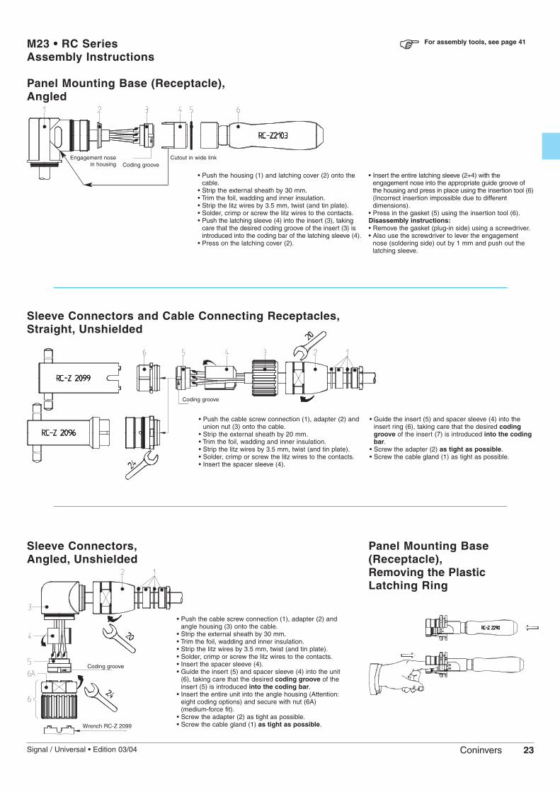
M23 • RC SeriesAssembly Instructions
Panel Mounting Base (Receptacle),Angled
• Push the housing (1) and latching cover (2) onto thecable.
• Strip the external sheath by 30 mm.• Trim the foil, wadding and inner insulation.• Strip the litz wires by 3.5 mm, twist (and tin plate).• Solder, crimp or screw the litz wires to the contacts.• Push the latching sleeve (4) into the insert (3), taking
care that the desired coding groove of the insert (3) isintroduced into the coding bar of the latching sleeve (4).
• Press on the latching cover (2).
Coding groove
• Insert the entire latching sleeve (2+4) with theengagement nose into the appropriate guide groove ofthe housing and press in place using the insertion tool (6)(Incorrect insertion impossible due to differentdimensions).
• Press in the gasket (5) using the insertion tool (6).Disassembly instructions:• Remove the gasket (plug-in side) using a screwdriver.• Also use the screwdriver to lever the engagement
nose (soldering side) out by 1 mm and push out thelatching sleeve.
Sleeve Connectors and Cable Connecting Receptacles,Straight, Unshielded
Coding groove
• Push the cable screw connection (1), adapter (2) andunion nut (3) onto the cable.
• Strip the external sheath by 20 mm.• Trim the foil, wadding and inner insulation.• Strip the litz wires by 3.5 mm, twist (and tin plate).• Solder, crimp or screw the litz wires to the contacts.• Insert the spacer sleeve (4).
• Guide the insert (5) and spacer sleeve (4) into theinsert ring (6), taking care that the desired codinggroove of the insert (7) is introduced into the codingbar.
• Screw the adapter (2) as tight as possible.• Screw the cable gland (1) as tight as possible.
Sleeve Connectors,Angled, Unshielded
Coding groove
Wrench RC-Z 2099
• Push the cable screw connection (1), adapter (2) andangle housing (3) onto the cable.
• Strip the external sheath by 30 mm.• Trim the foil, wadding and inner insulation.• Strip the litz wires by 3.5 mm, twist (and tin plate).• Solder, crimp or screw the litz wires to the contacts.• Insert the spacer sleeve (4).• Guide the insert (5) and spacer sleeve (4) into the unit
(6), taking care that the desired coding groove of theinsert (5) is introduced into the coding bar.
• Insert the entire unit into the angle housing (Attention:eight coding options) and secure with nut (6A)(medium-force fit).
• Screw the adapter (2) as tight as possible.• Screw the cable gland (1) as tight as possible.
Panel Mounting Base(Receptacle),Removing the PlasticLatching Ring
For assembly tools, see page 41
Engagement nosein housing
Cutout in wide link

24 Signal / Universal • Edition 03/04Coninvers
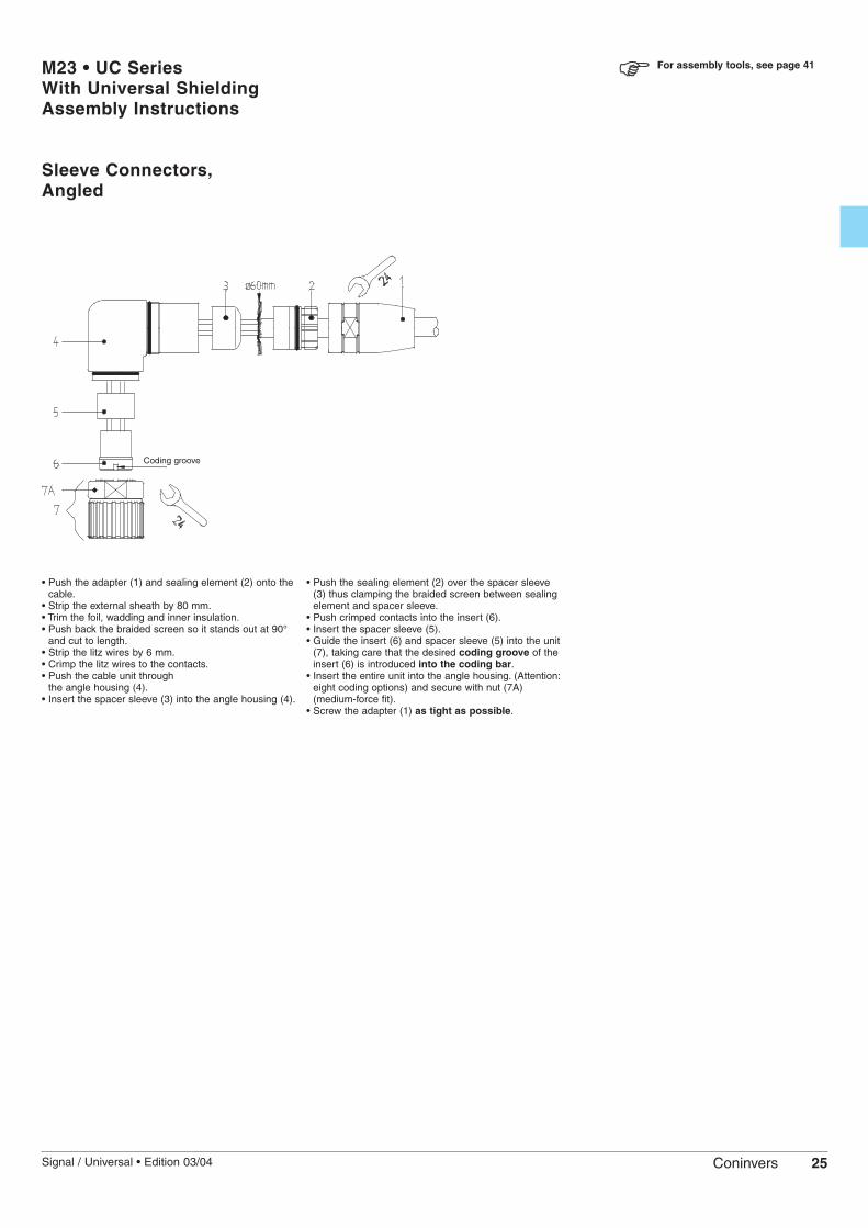
M23 • UC SeriesWith Universal ShieldingAssembly Instructions
Sleeve Connectors and Cable Connecting Receptacles,Straight
For assembly tools, see page 41
• Push the adapter (1) and the sealing element (3) withthe gasket (2) onto the cable.
• Strip the external sheath by 30 mm.• Push back the braided screen so it stands out at 90°
and cut to length.• Trim the foil, wadding and inner insulation.• Strip the litz wires by 3.5 mm, twist (and tin plate).• Solder, crimp or screw the litz wires to the contacts.
• Insert the spacer sleeve (4).• Guide the insert (5), the spacer sleeve (4) and the
sealing element (3) with the gasket (2) into the insertring (6), taking care that the desired coding groove ofthe insert (5) is introduced into the coding bar of thespacer sleeve (6).
• Screw the adapter (1) as tight as possible.
Coding groove
25Signal / Universal • Edition 03/04 Coninvers
M23 • UC SeriesWith Universal ShieldingAssembly Instructions
Sleeve Connectors,Angled
For assembly tools, see page 41
• Push the adapter (1) and sealing element (2) onto thecable.
• Strip the external sheath by 80 mm.• Trim the foil, wadding and inner insulation.• Push back the braided screen so it stands out at 90°
and cut to length.• Strip the litz wires by 6 mm.• Crimp the litz wires to the contacts.• Push the cable unit through
the angle housing (4).• Insert the spacer sleeve (3) into the angle housing (4).
• Push the sealing element (2) over the spacer sleeve(3) thus clamping the braided screen between sealingelement and spacer sleeve.
• Push crimped contacts into the insert (6).• Insert the spacer sleeve (5).• Guide the insert (6) and spacer sleeve (5) into the unit
(7), taking care that the desired coding groove of theinsert (6) is introduced into the coding bar.
• Insert the entire unit into the angle housing. (Attention:eight coding options) and secure with nut (7A)(medium-force fit).
• Screw the adapter (1) as tight as possible.
Coding groove

26 Signal / Universal • Edition 03/04Coninvers
Bayonet • TU SeriesSignal Circular ConnectorsProduct Selection
CombinationsThe product chart show the possiblecombinations of sleeve housing andconnecting housing or panel mountingbase.The sleeve connectors and cableconnecting receptacles are fitted with auniversal shield connection for cablediameters up to 14.5 mm.
Selection of connectorsThe modular system allows the individualconnector to be selected from a definednumber of articles. To specify a connectorfor the device and mounting side, the
housing is supplemented by thecorresponding contact insert, includingcontacts.
HousingSleeve housings with universal shielding, page 30
Connecting housings with universal shielding, page 30
BTGGUM BTWGUM
BKGGUM
Panel mounting bases
BAAGA
Front mounting, page 31
BAIGF
With universal shielding
With universal shielding
ShieldedBAIGR
Rear mounting, page 31
27Signal / Universal • Edition 03/04 Coninvers
The product chart provides an overviewof the available components.
Contact insert including contacts
The connectors are fitted with auniversal shield connection for cablediameters up to 14.5 mm. Shieldedcable glands with a cable clamp typecage and shielded sleeve are notrequired.
Solder contact inserts, page 346 to 19-position
Crimp contact inserts, pages 35-376 to 19-position
Screw contact inserts, page 356, 7 and 9-position
Direct PCB connection, page 38With 6 to 17-position dip solder contacts
Contact inserts
Contact inserts
Contact inserts
Contact inserts
LSR... LBL...
C..S... C..B...
SSR... SBL...
ES... EB...
Further contact inserts/dip solder contactsavailable on request.
Type/housing Free solder pin lengthdesign A B C D
[mm] [mm] [mm] [mm]
BAAGA – 3.5 9.0 16.5
BAIGF 2.5 3.5 9.0 16.5
BAIGR 2.5 3.5 9.0 16.5
Mou
ntin
g fla
nge
for
pane
l mou
ntin
g ba
se
For reasons of safety, only female contacts may beused in the live part of the connector.
For reasons of safety, only female contacts may beused in the live part of the connector.
The connectors are fitted with auniversal shield connection for cablediameters up to 14.5 mm. Shieldedcable glands with a cable clamp typecage and shielded sleeve are notrequired.

28 Signal / Universal • Edition 03/04Coninvers
Bayonet • TU SeriesTechnical Data
Mechanical data:Housing material: Machined component: copper-zinc alloy (CuZn), die-cast part: zinc (GD-Zn)
Housing surface: Nickel-plated (standard)
Insulating body: Thermoplastic polyester (PBT), polyamide (PA 66); storage at 15-35 °C, 40-70 % rel. humidityInflammability: UL 94 V0
Contact material: Copper-zinc alloy (CuZn)
Contact surface: Nickel-plated (Ni) with gold layer (Au) and passivated
Contact connection type: Solder cup, crimp and screw versions, dip solder pin
Gasket and O-ring: Fluorine rubber (FPM)
Flat gasket: Perbunane (NBR with fabric insert) fluorine rubber (FPM)
Temperature range: -40°C/+125°C (long-term temperature)
Conductor entry: EMC design, for cable diameters 2 - 14.5 mm
Locking method: Bayonet locking, bayonet ring Ø 29.3 mm
Mechanical insertion/withdrawal cycles: Standard: 50, more on request
Degree of protection: EMC version: IP67 in the locked state
Electrical data:
Number of positions 6, 7 9(8+1) 9(6+3) 12 16 17 19(16+3)
Contacts 6, 7 8 + 1 6 + 3 11, 12 15, 16 16, 17 16 + 3Contact Ø [mm] 2 1 2 1 2 1 1 1 1 1.5Conductor Solder connection contacts x [mm2] 6 (7) x 2.5 8x1.0+1x2.5 6x1.0+3x2.5 12 x 2.5 16 x 1.0 17 x 1.0 16 x 1.0 + 3 x 1.0cross section Crimp connection contacts x [mm2] 6 (7) x 2.5 8x0.56+1x2.5 12 x 0.56 16 x 0.56 17 x 0.56 16x1.0+3x1.5Nominal/rated current [A] 20 8 20 8 20 8 8 8 8 10Nominal/rated voltage [V] 300 300 150 150 150 150 150Test voltage [kV AC] 2.5 2.5 1.5 1.5 1.5 1.5 1.5Surge voltage category 1) II II II II II II IIInsulation resistance [Ω] ≥1016 ≥1016 ≥1012 ≥1012 ≥1012 ≥1012 ≥1012
Contact resistance [mΩ] ≤3 ≤3 ≤3 ≤3 ≤3 ≤3 ≤3Contamination class in acc. with IEC 664-1 2 (31) 2 (31) 2 (31) 2 (31) 2 (31) 2 (31) 2 (31)
1) Reference: DIN EN 61984:2001 (see also appendix of technical terms, page 43).
Derating curve 12-position cable and sleeve connectors
Temperature [°C]
Cur
rent
[A
]
Shield attenuation curve Based on DIN 47250-6/01.83
Frequency [MHz]
Atte
nuat
ion
[dB
]

29Signal / Universal • Edition 03/04 Coninvers
Bayonet • TU SeriesPin Assignments and Coding
Number of positions
6-position
Solder / crimp / screwPages 34 - 39
7-position
Solder / crimp / screwPages 34 - 39
9-position(6+3)Solder
Pages 34, 38
9-position(8+1)
Solder / crimp / screwPages 34 - 39
12-position
Solder / crimpPages 34 - 39
16-position
SolderPages 34, 38
16-position
CrimpPages 35 - 37
17-position
SolderPages 34, 38
17-position
CrimpPages 35 - 37
19-position(16+3)
Solder / crimpPages 34 -37
Clockwise
Male
Counter-clockwise
Female
Counter-clockwise
Male
Clockwise
Female
Contact chamber numbering(view of plug-in side)
Other coding versions can be configured manually or mechanically on request.
Direction of contact chambernumbering(view of plug-in side)
Male, clockwise(standard)
Male, counter-clockwise(opposite direction)
Female, counter-clockwise(standard)
Female, clockwise(opposite direction)

30 Signal / Universal • Edition 03/04Coninvers
Bayonet • TU SeriesConnecting/Sleeve Housings,Universal Shielding
Sleeve connectors for connecting housings andpanel mounting bases
BTGGUM, BTWGUM
Description
Sleeve housing,straight, with universal shielding, metal for external cable diameters from 2 mm to 14.5 mm
Bayonet sleeve housing,angled, with universal shielding, metal for external cable diameters from 2 mm to 14.5 mm
Bayonet connecting housing,straight, with universal shielding, metal for external cable diameters from 2 mm to 14.5 mm
Type/housing Order No. Pcs./design Pkt.
10
BTGGUM TU-00000008UDU
10
BTWGUM TU-0000000TUDU
BTWGUM
BTGGUM
Cable connecting receptacles for shielded free connections
BKGGUM
Type/housing Order No. Pcs./design Pkt.
10
BKGGUM TU-00000009UDU
BKGGUM
Type description
BT G GU M
TypeBT Bayonet sleeve connectorBK Bayonet cable conn. receptacle
FormG StraightW Angled
EMC protectionGU With universal shielding
Housing materialM Metal
Signal connectors in the TU series featurea bayonet locking system which is easy touse but robust at the same time.Like the signal connectors with M23 screwlocking, the TU series is completelymodular in design and uses the sameinsulating bodies/contacts.The TU series is based on UC connectors,i.e. it also offers more cabling space andcan accommodate larger cable diameters.The shielding function and the cableclamping are universal. It is not necessaryto adapt the shielding elements to thecables used.
Unlike plugs, connectors must not beplugged in or unplugged under load, in
order to avoid damage caused by contact erosion.
For corresponding contact inserts, see pages 34-39
31Signal / Universal • Edition 03/04 Coninvers
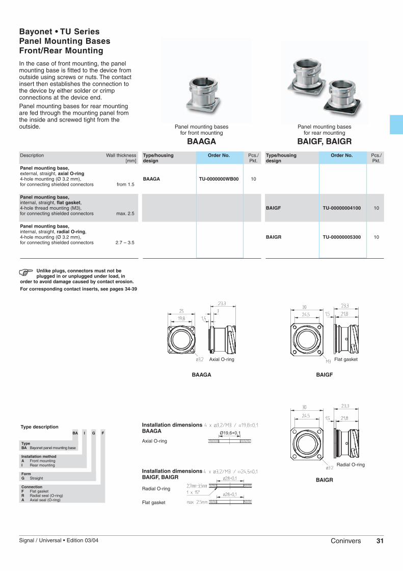
Bayonet • TU SeriesPanel Mounting BasesFront/Rear Mounting
Panel mounting bases for front mounting
BAAGA
Description Wall thickness[mm]
Panel mounting base,external, straight, axial O-ring4-hole mounting (Ø 3.2 mm), for connecting shielded connectors from 1.5
Panel mounting base,internal, straight, flat gasket, 4-hole thread mounting (M3), for connecting shielded connectors max. 2.5
Panel mounting base,internal, straight, radial O-ring, 4-hole mounting (Ø 3.2 mm), for connecting shielded connectors 2.7 – 3.5
Type/housing Order No. Pcs./design Pkt.
BAAGA TU-0000000WB00 10
Unlike plugs, connectors must not beplugged in or unplugged under load, in
order to avoid damage caused by contact erosion.
For corresponding contact inserts, see pages 34-39
Installation dimensions BAAGA
BAAGA
In the case of front mounting, the panelmounting base is fitted to the device fromoutside using screws or nuts. The contactinsert then establishes the connection tothe device by either solder or crimpconnections at the device end.Panel mounting bases for rear mountingare fed through the mounting panel fromthe inside and screwed tight from theoutside.
Type descriptionBA I G F
TypeBA Bayonet panel mounting base
Installation methodA Front mounting I Rear mounting
FormG Straight
ConnectionF Flat gasketR Radial seal (O-ring)A Axial seal (O-ring)
Axial O-ring
Flat gasket
Axial O-ring
Panel mounting bases for rear mounting
BAIGF, BAIGR
Type/housing Order No. Pcs./design Pkt.
BAIGF TU-00000004100 10
BAIGR TU-00000005300 10
BAIGR
BAIGF
Flat gasket
Radial O-ringInstallation dimensions BAIGF, BAIGR
Radial O-ring

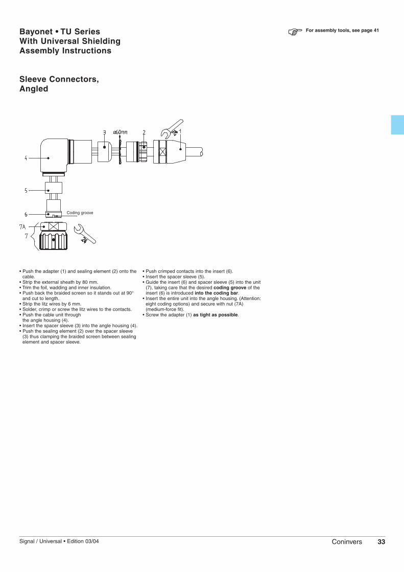
32 Signal / Universal • Edition 03/04Coninvers
Bayonet • TU SeriesWith Universal ShieldingAssembly Instructions
Sleeve Connectors and Cable Connecting Receptacles,Straight
For assembly tools, see page 41
• Push the adapter (1) and the sealing element (3) withthe gasket (2) onto the cable.
• Strip the external sheath by 30 mm.• Push back the braided screen so it stands out at 90°
and cut to length.• Trim the foil, wadding and inner insulation.• Strip the litz wires by 3.5 mm, twist (and tin plate).• Solder, crimp or screw the litz wires to the contacts.• Insert the spacer sleeve (4).
• Guide the insert (5), the spacer sleeve (4) and thesealing element (3) with the gasket (2) into the insertring (6), taking care that the desired coding groove ofthe insert (5) is introduced into the coding bar of thespacer sleeve (6).
• Screw the adapter (1) as tight as possible.
Coding groove
33Signal / Universal • Edition 03/04 Coninvers
Bayonet • TU SeriesWith Universal ShieldingAssembly Instructions
Sleeve Connectors,Angled
For assembly tools, see page 41
• Push the adapter (1) and sealing element (2) onto thecable.
• Strip the external sheath by 80 mm.• Trim the foil, wadding and inner insulation.• Push back the braided screen so it stands out at 90°
and cut to length.• Strip the litz wires by 6 mm.• Solder, crimp or screw the litz wires to the contacts.• Push the cable unit through
the angle housing (4).• Insert the spacer sleeve (3) into the angle housing (4).• Push the sealing element (2) over the spacer sleeve
(3) thus clamping the braided screen between sealingelement and spacer sleeve.
• Push crimped contacts into the insert (6).• Insert the spacer sleeve (5).• Guide the insert (6) and spacer sleeve (5) into the unit
(7), taking care that the desired coding groove of theinsert (6) is introduced into the coding bar.
• Insert the entire unit into the angle housing. (Attention:eight coding options) and secure with nut (7A)(medium-force fit).
• Screw the adapter (1) as tight as possible.
Coding groove

34 Signal / Universal • Edition 03/04Coninvers
RC / UC / TU SeriesContact Inserts6 to 19-Position
Contact insert and solder contactsmale/female
L ...
Description
Contact insert, 6-positionContacts: 6 x Ø 2.0 mm
Contact insert, 7-positionContacts: 7 x Ø 2.0 mm
Contact insert, 9-position (6+3)Contacts: 6 x Ø 1.0 mm, 3 x Ø 2.0 mm
Contact insert, 9-position (8+1)Contacts: 8 x Ø 1.0 mm, 1 x Ø 2.0 mm
Contact insert, 12-positionContacts: 12 x Ø 1.0 mm
Contact insert, 16-positionContacts: 16 x Ø 1.0 mm
Contact insert, 17-positionContacts: 17 x Ø 1.0 mm
Contact insert, 19-position (16+3)Contacts: 16 x Ø 1.0 mm, 3 x Ø 1.5 mm
Crimping pliers for crimp contacts (see also page 41)
Technical data (see also pages 12, 28)
Ambient temperature [°C]
Connection cross section [mm2]For contact Ø 1.0 mm / 1.5 mmFor contact Ø 2.0 mm
MaterialsContactContact surfaceContact insert
Type Order no. Pcs./Pkt.
10LSR 6 RC-06P1N120000LBL 6 RC-06S1N120000
10LSR 7 RC-07P1N120000LBL 7 RC-07S1N120000
10LSR 6+3 RC-63P1N120000LBL 6+3 RC-63S1N120000
10LSR 8+1 RC-09P1N120000LBL 8+1 RC-09S1N120000
LSL 8+1 RC-09P2N120000LBR 8+1 RC-09S2N120000
10LSR 12 RC-12P1N120000LBL 12 RC-12S1N120000LSL 12 RC-12P2N120000LBR 12 RC-12S2N120000
10LSR 16 RC-16P1N120000LBL 16 RC-16S1N120000
10LSR 17 RC-17P1N120000LBL 17 RC-17S1N120000LSL 17 RC-17P2N120000LBR 17 RC-17S2N120000
10LSR 16+3 RC-19P1N120000LBL 16+3 RC-19S1N120000
–
-40 to +125
≤ 1≤ 2.5
CuZNNi with gold layer
PBT
The contact inserts with the contact carriersand the contacts are available for thefollowing connection types:– Soldering– Crimping– Screwing– Dip soldering for printed circuit boardsIn the case of each connection system,contact inserts are available for different – Pin assignments– Male and female contacts – And for the most part, clockwise or
counter-clockwise numbering of thecontact chamber
Ordering instructions:The first step is to determine theconnection system – soldering, dipsoldering, crimping or screwing. Thenumber of positions corresponds to theapplication and the number of cores. Theselection male or female depends on thecircuitry. The direction of the numberingdepends on individual requirements (seepin assignments, pages 13, 29).The standard numbering direction is (view of plug-in side):– Male contact carrier, clockwise– Female contact carrier, counter-clockwise
This ensures that the plug connectionsmatch.
Direction of contact chambernumbering(view of plug-in side)
Male, clockwise(standard)
Male, counter-clockwise(opposite direction)
Female, counter-clockwise(standard)
Female, clockwise(opposite direction)
Housing termination
Type description
L S R 12
Connection systemL Solder connectionCR Crimp connection
Rolled crimp contactsCD Crimp connection
Turned crimp contactsS Screw connection
ContactS Male B Female
NumberingR ClockwiseL Counter-clockwise
No. of positions6 6-position6K 6-position, lower connection range7 7-position7K 7-position, lower connection range6+3 9-position (6+3)8+1 9-position (8+1)8+1K 9-position (8+1), lower connection range12 12-position16 16-position17 17-position16+3 19-position (16+3)16+2+PE 19-position (16+2+PE) with crimp

35Signal / Universal • Edition 03/04 Coninvers
Contact insert and screw contactsmale/female
S ...
Contact insert and crimp contacts, turnedmale/female
CD ...
Type Crimp range Order no. Pcs./(see below *) Pkt.
10CDSR 6 C RC-06P1N8B0000CDBL 6 C RC-06S1N8B0000CDSR 6K D RC-06P1N8K0000CDBL 6K D RC-06S1N8K0000
10CDSR 7 C RC-07P1N8B0000CDBL 7 C RC-07S1N8B0000CDSR 7K D RC-07P1N8K0000CDBL 7K D RC-07S1N8K0000
10CDSR 8+1 8xB+1xC RC-09P1N8C0000CDBL 8+1 8xB+1xC RC-09S1N8C0000CDSL 8+1 8xB+1xC RC-09P2N8C0000CDBR 8+1 8xB+1xC RC-09S2N8C0000CDSR 8+1K 8xB+1xD RC-09P1N8L0000CDBL 8+1K 8xB+1xD RC-09S1N8L0000CDSL 8+1K 8xB+1xD RC-09P2N8L0000CDBR 8+1K 8xB+1xD RC-09S2N8L0000
10CDSR 12 B RC-12P1N8D0000CDBL 12 B RC-12S1N8D0000CDSL 12 B RC-12P2N8D0000CDBR 12 B RC-12S2N8D0000
10CDSR 16 B RC-16P1N8D0000CDBL 16 B RC-16S1N8D0000
10CDSR 17 B RC-17P1N8D0000CDBL 17 B RC-17S1N8D0000
10CDSR 16+2+PE B RC-1RP1NRM0000CDBL 16+2+PE B RC-1RS1NRM0000
Crimping pliers RC 2,5 RC-Z2378 1
-40 to +125
* Crimp range B: 0.14 – 0.56 * Crimp range C: 1.5 – 2.5; * Crimp range D: 1.0 – 1.5
CuZNNi with gold layer
PBT
Contact insert and crimp contacts, rolledmale/female
CR ...
Type Crimp range Order no. Pcs./(see below *) Pkt.
10CRSR 12 A RC-12P1N8E0000CRBL 12 A RC-12S1N8E0000CRSL 12 A RC-12P2N8E0000CRBR 12 A RC-12S2N8E0000
10CRSR 17 A RC-17P1N8E0000CRBL 17 A RC-17S1N8E0000
Crimping pliers RC 0,56 RC-Z2130 1
-40 to +125
* Crimp range A: 0.22 – 0.56 –
CuZNNi with gold layer
PBT
Housing termination
Crimp contacts/contact carriersseparate, see page 36
Type Order no. Pcs./Pkt.
10SSR 6 RC-06P1NS20000SBL 6 RC-06S1NS20000
10SSR 7 RC-07P1NS20000SBL 7 RC-07S1NS20000
10SSR 8+1 RC-09P1NS20000SBL 8+1 RC-09S1NS20000
–
-40 to +125
≤ 0.75≤ 1.5
CuZNNi with gold layer
PBT
Crimp contacts/contact carriersseparate, see page 36
CDSR 16+2+PE / CDBL 16+2+PE cannot be combined with housing AAWF

36 Signal / Universal • Edition 03/04Coninvers
RC / UC / TU SeriesCrimp Contact Carriers andCrimp Contacts Separate
Description
6-position crimp contact insertfor contacts 6 x Ø 2.0 mm
7-position crimp contact insertfor contacts 7 x Ø 2.0 mm
9-position (8+1) crimp contact insertfor contacts 8 x Ø 1.0 mm / 1 x Ø 2.0 mm
12-position crimp contact insertfor contacts 12 x Ø 1.0 mm
16-position crimp contact insertfor contacts 16 x Ø 1.0 mm
17-position crimp contact insertfor contacts 17 x Ø 1.0 mm
19-position (16+2+PE) crimp contact insertfor contacts
16 x Ø 1.0 mm / 2 x Ø 1.5 mm / 1 x Ø 1.5 mm
Crimping pliers for crimp contacts (see also page 41)
Connection cross section for 6 to 17-pos.crimp contact insert [mm2]for contact Ø 1.0 mm for contact Ø 2.0 mm
Connection cross section for 19-pos. (16+2+PE)crimp contact insert [mm2]for contact Ø 1.0 mmfor contact Ø 1.5 mm
The contact carriers and the male andfemale crimp contacts can also be orderedseparately for 6 to 9-position connectors.
Other contact inserts/contactsavailable on request
Type description of crimp contacts
RC- ST CD- 1/14,8/014-0,56
Contact seriesRC
Contact typeST MaleSP Male PE contactBU FemaleBP Female PE contact
Connection systemCR Crimp connection
Rolled crimp contactsCD Crimp connection
Turned crimp contacts
Contact diameter/contact length [mm]/Crimp range [mm2]
Type description of contact carrierswithout crimp contacts
RC- IC S R 6
Contact seriesRC
Contact carrierIC Crimp insulating body
ContactS Male B Female
NumberingR ClockwiseL Counter-clockwise
No. of positions6 6-position7 7-position8+1 9-position (8+1)12 12-position16 16-position17 17-position16+2+PE 19-position (16+2+PE)
Type Order No. Pcs./Pkt.
10RC-ICSR 6 RC-06P1N8A0000RC-ICBL 6 RC-06S1N8A0000
10RC-ICSR 7 RC-07P1N8A0000RC-ICBL 7 RC-07S1N8A0000
10RC-ICSR 8+1 RC-09P1N8A0000RC-ICSL 8+1 RC-09P2N8A0000
RC-ICBL 8+1 RC-09S1N8A0000RC-ICBR 8+1 RC-09S2N8A0000
10RC-ICSR 12 RC-12P1N8A0000RC-ICSL 12 RC-12P2N8A0000
RC-ICBL 12 RC-12S1N8A0000RC-ICBR 12 RC-12S2N8A0000
10RC-ICSR 16 RC-16P1N8A0000RC-ICBL 16 RC-16S1N8A0000
10RC-ICSR 17 RC-17P1N8A0000RC-ICBL 17 RC-17S1N8A0000
10RC-ICSR 16+2+PE RC-1RP1NRA0000
RC-ICBL 16+2+PE RC-1RS1NRA0000
Crimp contact carriers separatemale/female
RC-ICS..., RC-ICB...

37Signal / Universal • Edition 03/04 Coninvers
Crimp contacts separate, rolledmale/female
RC-STCR-..., RC-BUCR-...
Type Order No. Pcs./ Included in contact insert Pkt. type (page 35)
10RC-STCR-1/14,8/0,22-0,56 RC-22P2000 CRSR 12/CRSL 12RC-BUCR-1/14,8/0,22-0,56 RC-22S2000 CRBL 12/CRBR 12
10RC-STCR-1/14,8/0,22-0,56 RC-22P2000 CRSR 17RC-BUCR-1/14,8/0,22-0,56 RC-22S2000 CRBL 17
Crimping pliers RC 0,56 RC-Z2130 1
Crimp range 0.22 – 0.56 –
– –
Crimp contacts separate, turnedmale/female
RC-S.CD-..., RC-B.CD-...
Type Order No. Pcs./ Included in contact insert Pkt. type (page 35)
10RC-STCD-2/14,8/1,0-1,5 RC-5CP2000 CDSR 6KRC-BUCD-2/14,2/1,0-1,5 RC-5CS2000 CDBL 6KRC-STCD-2/14,8/1,5-2,5 RC-5AP2000 CDSR 6RC-BUCD-2/14,2/1,5-2,5 RC-5AS2000 CDBL 6
10RC-STCD-2/14,8/1,0-1,5 RC-5CP2000 CDSR 7KRC-BUCD-2/14,2/1,0-1,5 RC-5CS2000 CDBL 7KRC-STCD-2/14,8/1,5-2,5 RC-5AP2000 CDSR 7RC-BUCD-2/14,2/1,5-2,5 RC-5AS2000 CDBL 7
10RC-STCD-1/14,8/0,14-0,56 RC-12P2000 CDSR 8+1/CDSR 8+1K
CDSL 8+1/CDSL 8+1KRC-STCD-2/14,8/1,0-1,5 RC-5CP2000 CDSR 8+1K/CDSL 8+1KRC-STCD-2/14,8/1,5-2,5 RC-5AP2000 CDSR 8+1/CDSL 8+1RC-BUCD-1/14,25/0,14-0,56 RC-12S2000 CDBL 8+1/CDBL 8+1K
CDBR 8+1/CDBR 8+1KRC-BUCD-2/14,2/1,0-1,5 RC-5CS2000 CDBL 8+1K/CDBR 8+1KRC-BUCD-2/14,2/1,5-2,5 RC-5AS2000 CDBL 8+1/CDBR 8+1
10RC-STCD-1/14,8/0,14-0,56 RC-12P2000 CDSR 12/CDSL 12RC-BUCD-1/14,25/0,14-0,56 RC-12S2000 CDBL 12/CDBR 12
10RC-STCD-1/14,8/0,14-0,56 RC-12P2000 CDSR 16RC-BUCD-1/14,25/0,14-0,56 RC-12S2000 CDBL 16
10RC-STCD-1/14,8/0,14-0,56 RC-12P2000 CDSR 17RC-BUCD-1/14,25/0,14-0,56 RC-12S2000 CDBL 17
10RC-STCD-1/24,3/0,25-0,5 RC-6LP2000 CDSR 16+2+PERC-STCD-1,5/24,3/0,75-1,0 RC-6EP2000 CDSR 16+2+PERC-SPCD-1,5/25,8/0,75-1,0 RC-6FP2000 CDSR 16+2+PE
RC-BUCD-1/16,5/0,25-0,5 RC-6LS2000 CDBL 16+2+PERC-BUCD-1,5/16,5/0,75-1,0 RC-6ES2000 CDBL 16+2+PERC-BPCD-1,5/16,5/0,75-1,0 RC-6FS2000 CDBL 16+2+PE
Crimping pliers RC 2,5 RC-Z2378 1
Crimp range 0.14 – 0.56 Crimp range 1.0 - 1.5; Crimp range 1.5 – 2.5
Crimp range 0.25 – 0.5Crimp range 0.75 – 1.0
38 Signal / Universal • Edition 03/04Coninvers
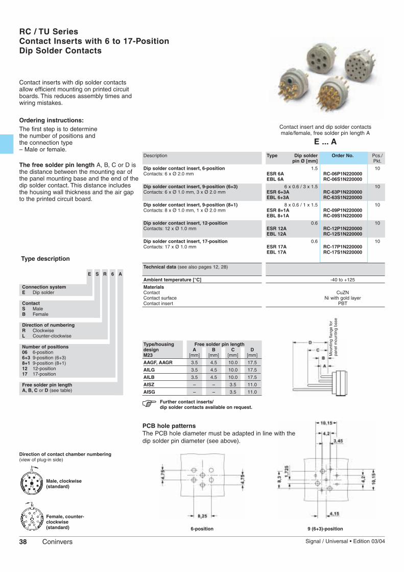
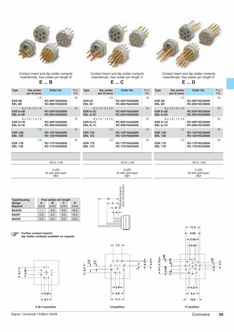
RC / TU SeriesContact Inserts with 6 to 17-PositionDip Solder Contacts
Contact insert and dip solder contactsmale/female, free solder pin length A
E ... A
Description
Dip solder contact insert, 6-positionContacts: 6 x Ø 2.0 mm
Dip solder contact insert, 9-position (6+3)Contacts: 6 x Ø 1.0 mm, 3 x Ø 2.0 mm
Dip solder contact insert, 9-position (8+1)Contacts: 8 x Ø 1.0 mm, 1 x Ø 2.0 mm
Dip solder contact insert, 12-positionContacts: 12 x Ø 1.0 mm
Dip solder contact insert, 17-positionContacts: 17 x Ø 1.0 mm
Technical data (see also pages 12, 28)
Ambient temperature [°C]
MaterialsContactContact surfaceContact insert
Type Dip solder Order No. Pcs./pin Ø [mm] Pkt.
1.5 10ESR 6A RC-06P1N220000EBL 6A RC-06S1N220000
6 x 0.6 / 3 x 1.5 10ESR 6+3A RC-63P1N220000EBL 6+3A RC-63S1N220000
8 x 0.6 / 1 x 1.5 10ESR 8+1A RC-09P1N220000EBL 8+1A RC-09S1N220000
0.6 10ESR 12A RC-12P1N220000EBL 12A RC-12S1N220000
0.6 10ESR 17A RC-17P1N220000EBL 17A RC-17S1N220000
-40 to +125
CuZNNi with gold layer
PBT
Contact inserts with dip solder contactsallow efficient mounting on printed circuitboards. This reduces assembly times andwiring mistakes.
Ordering instructions:The first step is to determine the number of positions and the connection type – Male or female.
The free solder pin length A, B, C or D isthe distance between the mounting ear ofthe panel mounting base and the end of thedip solder contact. This distance includesthe housing wall thickness and the air gapto the printed circuit board.
Further contact inserts/dip solder contacts available on request.
Direction of contact chamber numbering(view of plug-in side)
Male, clockwise(standard)
Female, counter-clockwise(standard) 6-position
Type/housing Free solder pin lengthdesign A B C DM23 [mm] [mm] [mm] [mm]
AAGF, AAGR 3.5 4.5 10.0 17.5
AILG 3.5 4.5 10.0 17.5
AILB 3.5 4.5 10.0 17.5
AISZ – – 3.5 11.0
AISG – – 3.5 11.0
PCB hole patternsThe PCB hole diameter must be adapted in line with thedip solder pin diameter (see above).
9 (6+3)-position
Type description
E S R 6 A
Connection systemE Dip solder
ContactS Male B Female
Direction of numberingR ClockwiseL Counter-clockwise
Number of positions06 6-position6+3 9-position (6+3)8+1 9-position (8+1)12 12-position17 17-position
Free solder pin lengthA, B, C or D (see table)
Mou
ntin
g fla
nge
for
pane
l mou
ntin
g ba
se
39Signal / Universal • Edition 03/04 Coninvers
Contact insert and dip solder contactsmale/female, free solder pin length D
E ... D
Contact insert and dip solder contactsmale/female, free solder pin length C
E ... C
Contact insert and dip solder contactsmale/female, free solder pin length B
E ... B
Type Dip solder Order No. Pcs./pin Ø [mm] Pkt.
1.5 10ESR 6B RC-06P1N320000EBL 6B RC-06S1N320000
6 x 1.0 / 3 x 1.5 10ESR 6+3B RC-63P1N320000EBL 6+3B RC-63S1N320000
8 x 1.0 / 1 x 1.5 10ESR 8+1B RC-09P1N320000EBL 8+1B RC-09S1N320000
1.0 10ESR 12B RC-12P1N320000EBL 12B RC-12S1N320000
1.0 10ESR 17B RC-17P1N320000EBL 17B RC-17S1N320000
-40 to +125
CuZNNi with gold layer
PBT
Type Dip solder Order No. Pcs./pin Ø [mm] Pkt.
1.5 10ESR 6C RC-06P1NA20000EBL 6C RC-06S1NA20000
6 x 1.2 / 3 x 1.5 10ESR 6+3C RC-63P1NA20000EBL 6+3C RC-63S1NA20000
8 x 1.2 / 1 x 1.5 10ESR 8+1C RC-09P1NA20000EBL 8+1C RC-09S1NA20000
1.2 10ESR 12C RC-12P1NA20000EBL 12C RC-12S1NA20000
1.2 10ESR 17C RC-17P1NA20000EBL 17C RC-17S1NA20000
-40 to +125
CuZNNi with gold layer
PBT
Type Dip solder Order No. Pcs./pin Ø [mm] Pkt.
1.5 10ESR 6D RC-06P1NC20000EBL 6D RC-06S1NC20000
6 x 1.2 / 3 x 1.5 10ESR 6+3D RC-63P1NC20000EBL 6+3D RC-63S1NC20000
8 x 1.2 / 1 x 1.5 10ESR 8+1D RC-09P1NC20000EBL 8+1D RC-09S1NC20000
1.2 10ESR 12D RC-12P1NC20000EBL 12D RC-12S1NC20000
1.2 10ESR 17D RC-17P1NC20000EBL 17D RC-17S1NC20000
-40 to +125
CuZNNi with gold layer
PBT
9 (8+1)-position 12-position 17-position
Further contact inserts/dip solder contacts available on request.
Type/housing Free solder pin lengthdesign A B C DBayonet [mm] [mm] [mm] [mm]
BAAGA – 3.5 9.0 16.5
BAIGF 2.5 3.5 9.0 16.5
BAIGR 2.5 3.5 9.0 16.5
Mou
ntin
g fla
nge
for
pane
l mou
ntin
g ba
se

Signal ConnectorsTools • Accessories
A range of protective caps is available forsignal connectors with M23 screw locking /bayonet locking to protect the contactelements in the case of a separate plugconnection.This prevents the ingress of dust andmoisture.The wire is fixed to the housing panel andprevents the protective cap from being lost.
40 Signal / Universal • Edition 03/04Coninvers
Metal protective cap
MSK...
Description Degree of protection inlocked state
Metal dust protection cap for IP 67M23 cable conn. receptacles and panel mounting conn.
Metal dust protection cap for M23 cable conn. IP67receptacles and panel mounting conn., with steel wire
Metal dust protection cap for IP67M23 sleeve connectors, with steel wire
Metal dust protection cap for bayonet cable conn. IP67receptacles and panel mounting conn, with steel wire
Plastic dust protection cap for IP40M23 cable conn. receptacles and panel mounting conn.
Plastic dust protection cap for IP40M23 sleeve connectors
Plastic dust protection cap for bayonet cable IP40conn. receptacles and panel mounting conn.
Plastic dust protection cap for IP40bayonet sleeve connectors
Plastic protective cap
KSK...
Type Order No. Pcs./Pkt.
MSK 1 RC-Z2104 10
MSK 2 RC-Z2064 10
MSK 3 RC-Z2062 10
MSK 4 TU-Z2317 10
Type Order No. Pcs./Pkt.
KSK 1 RC-Z2059 10
KSK 3 RC-Z2058 10
KSK 4 TU-Z2002 10
KSK 5 TU-Z2003 10
M23 • UC SeriesCable Gaskets
Single gaskets are also available for thesleeve and connecting housings in the M23UC series in addition to the universalnotched sealing rings which are included inthe scope of supply. These can be obtainedto suit the given cable diameter.Sleeve and connecting housings with anadditional thread can be equipped with asecond cable strain relief for increasedloads. Notched sealing rings,
single gaskets
PKV...
Description
Notched sealing ringfor cable diameters6/8/10/12.5/15 mm
Single gasket Cable diameter9 mm
10 mm12 mm14 mm
15.5 mm
Double bracket strain relief for additional Pg thread Cable entry
Pg 13.5Pg 16
Double bracket strain relief forsleeve and connecting housings
PZKV DB...
Type Order No. Pcs./Pkt.
10PKV 6/8/10/12,5/15 UC-Z2351
10PKV 09 UC-Z2343PKV 10 UC-Z2344PKV 12 UC-Z2346PKV 14 UC-Z2348PKV 15,5 UC-Z2349
Type Order No. Pcs./Pkt.
10PZKV DB 13,5 RC-Z2036PZKV DB 16 UC-Z2039
41Signal / Universal • Edition 03/04 Coninvers
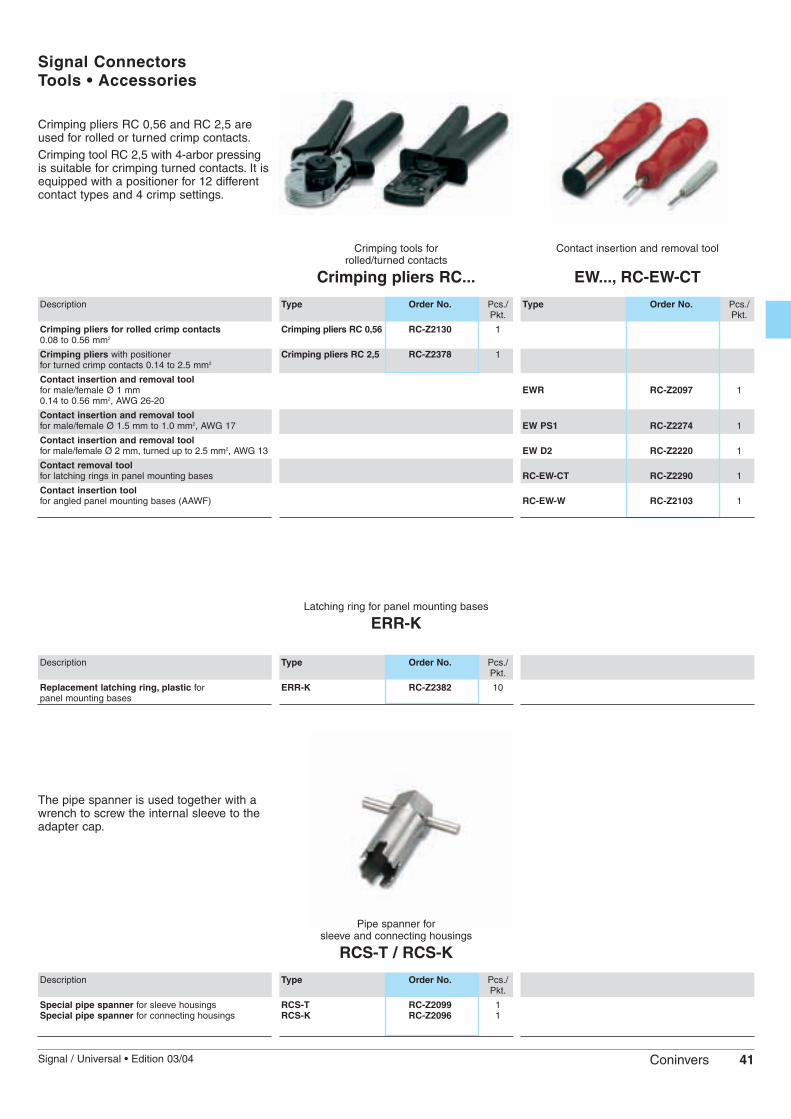
Latching ring for panel mounting bases
ERR-K
Description
Replacement latching ring, plastic forpanel mounting bases
The pipe spanner is used together with awrench to screw the internal sleeve to theadapter cap.
Pipe spanner forsleeve and connecting housings
RCS-T / RCS-K
Description
Special pipe spanner for sleeve housingsSpecial pipe spanner for connecting housings
Signal ConnectorsTools • Accessories
Type Order No. Pcs./Pkt.
ERR-K RC-Z2382 10
Type Order No. Pcs./Pkt.
RCS-T RC-Z2099 1RCS-K RC-Z2096 1
Crimping pliers RC 0,56 and RC 2,5 areused for rolled or turned crimp contacts.Crimping tool RC 2,5 with 4-arbor pressingis suitable for crimping turned contacts. It isequipped with a positioner for 12 differentcontact types and 4 crimp settings.
Crimping tools for rolled/turned contacts
Crimping pliers RC...
Description
Crimping pliers for rolled crimp contacts0.08 to 0.56 mm2
Crimping pliers with positionerfor turned crimp contacts 0.14 to 2.5 mm2
Contact insertion and removal tool for male/female Ø 1 mm0.14 to 0.56 mm2, AWG 26-20
Contact insertion and removal tool for male/female Ø 1.5 mm to 1.0 mm2, AWG 17
Contact insertion and removal tool for male/female Ø 2 mm, turned up to 2.5 mm2, AWG 13
Contact removal tool for latching rings in panel mounting bases
Contact insertion toolfor angled panel mounting bases (AAWF)
Contact insertion and removal tool
EW..., RC-EW-CT
Type Order No. Pcs./Pkt.
Crimping pliers RC 0,56 RC-Z2130 1
Crimping pliers RC 2,5 RC-Z2378 1
Type Order No. Pcs./Pkt.
EWR RC-Z2097 1
EW PS1 RC-Z2274 1
EW D2 RC-Z2220 1
RC-EW-CT RC-Z2290 1
RC-EW-W RC-Z2103 1

Signal Connectors Ordering Information
Description
Sleeve housing, unshielded with Pg 11
Solder contact carrier, 17-position, male
Cable gland
Connecting housing, unshielded with Pg 11
Solder contact carrier, 17-position, female
Type/housing Order No. Qty.design
TGUM 11 RC-00000001200 1
LSR 17 RC-17P1N120000 1
KVD 11 RC-Z2196 2
KGUM 11 RC-00000007200 1
LBL 17 RC-17S1N120000 1
Coninvers circular connectors are suppliedas individual components.Orders are dispatched directly from thewarehouse, thus enabling short deliverytimes.Flexible combinations of housings, cableglands and contact inserts facilitatewarehousing.
Ordering example: 17-position cable connector (sleeve connector and cable connecting receptacle)
Description
9-pos. crimp contact insert, male, clockwise
Crimp contacts separate, turned Ø 1.0Crimp range 0.14-0.56 mm2
Crimp contacts separate, turned Ø 2.0Crimp range 1.0-1.5 mm2
Type Order No. Qty.
RC-ICSR 8+1 RC-09P1N8A0000 1
RC-STCD-1/14,8/01,4-0,56 RC-12P2000 8
RC-STCD-2/14,8/1,0-1,5 RC-5CP2000 1
Ordering example: 9-position (8+1) male crimp contact carrier separate and crimp contacts separate
Description
Panel mounting base, external, straight
Solder contact carrier, 17-position, female
Type/housing Order No. Qty.design
AAGF RC-00000002200 1
LBL 17 RC-17S1N120000 1
Ordering example: 17-position panel mounting connector (receptacle)
42 Signal / Universal • Edition 03/04Coninvers
AppendixTechnical Terms
The explanations of the most importanttechnical terms used in the catalog relyheavily on explanations given in VDE0627 (DIN EN 61984). Please consultthis standard should you require moredetailed descriptions than those givenhere. All explanations refer toconnectors.
Connector
This must be differentiated from theterm plug or plug-in socket device. Aconnector is a component to whichelectrical conductors (cables) areconnected in order to connect these to,or disconnect them from, anothercomponent or device. When used inaccordance with their designated use,connectors must not be inserted orwithdrawn under voltage.
Insertion/withdrawal cycle
An insertion/withdrawal cycle refers to aconnection and disconnection procedurein the isolated, off-load state.
Upper limit temperature, lower limittemperature (temperature range)
Maximum permitted temperature atwhich a connector may be operated. Itincludes the increase in temperature ofthe contacts caused by electricity andthe ambient temperature.
Nominal voltage
The term nominal voltage is usedsynonymously with the term ratedvoltage. Rated voltage is the voltageused for dimensioning connectors.Some operating properties are definedwith reference to this.
The equation specified in the data sheetbetween effective AC voltage value Urms(where Umax = 1.414 x Urms) and theDC voltage refers to the electricaltransmission capacity.
Nominal current
The term nominal current is usedsynonymously with the term ratedcurrent. The rated current is the currentwhich the connector can carrycontinuously (without interruption) at anambient temperature of 25°C and whichflows through all the connector contactswhich are connected to the largestpossible conductor. The upper limittemperature is not exceeded.
Test voltage (see also IEC 664-1)
The term test voltage is usedsynonymously with the term rated surgevoltage. It refers to the defined capabilityof the insulation to withstand anticipatedsurge voltages. The impulse withstandvoltage is the highest peak value of asurge voltage with a specifiedcharacteristic (n x KV (1.2/50 µs) whichdoes not cause insulation breakdownunder defined conditions.
Surge voltage category (see also IEC 664-1)
Classification of electrical device(connector) according to anticipatedsurge voltage state. There are 4 surgevoltage categories. The category classdepends on the level of the nominalvoltage (operating voltage) and theselected rated surge voltage or theamplitude depending on the givendesign (1.2/50 µs).
Surge voltage category II:
Connectors for applications in systemsor system parts for which lightningprotection voltages do not need to bespecified.
Surge voltage category III
Connectors for applications in systemsor system parts for which lightningprotection voltages do not need to bespecified, but for which specialrequirements are defined regarding thesafety and availability of the connector.
Contamination class (see also IEC 664-1)
Specification of a numeric value (1 to 4)for a category/class which characterizesthe contamination to be anticipated inthe immediate vicinity of the connector.Accumulations of solid, liquid or gaseousforeign matter cause a decrease in thebreakdown strength or surfaceresistance of the insulation. Thecontamination class depends on therated voltage and the material used. Thisis used to calculate the minimum valuesfor the air and creepage distances whichare incorporated in the dimensioning ofthe connector.
Degrees of protection (DIN VDE 0470-1; EN 60529)
The degree of protection of housings isspecified according to an “IP”classification. In the case of connectors,this specification is designed to ensure:
• Protection of persons with regard toaccess to dangerous parts (touchprotection).• Protection of the connector with regardto the ingress of solid foreign bodies(protection against ingress of solidforeign bodies).• Protection of the connector with regardto damage caused by the ingress ofwater (protection against water).
IP 6 7 C S
Code letters
0-6 : Touch protection/Protection against foreign bodies
0-8 : Water protection
(Optional: A,B,C,D)
(Optional: H,M,S,W)
Example: IP66/67:Touch protection: Protection againsttouching a wireProtection against foreign bodies: Dust-tightWater protection: Protection againstpowerful jetting and temporaryimmersion in water
The technical data specified by Coninvers refersexclusively to connectors. All specifications are non-
binding product descriptions.
No liability for typing/printing errors. Subject to changewithout notice.
The general terms of business of Coninvers GmbH applyexclusively.Samples for presentation are not tested with reference to thetechnical properties specified in the catalog.
43Signal / Universal • Edition 03/04 Coninvers
44 Signal / Universal • Edition 03/04Coninvers
AppendixIndex of order numbers in alphabetical order
Type Order No. Page
AAAGF RC-00000002200 18AAGG RC-0000000B2FZ 18AAGR RC-0000000WQ00 18AALZ RC-00000006100 18AAWF RC-0000000A000 18AIGG RC-0000000C0FZ 19AIGZ RC-0000000Q0FZ 19AILB RC-00000005200 19AILG RC-00000004200 19AISG RC-0000000E000 19AISZ RC-0000000H000 19
BBAAGA TU-0000000WB00 31BAIGF TU-00000004100 31BAIGR TU-00000005300 31BKGGUM TU-00000009UDU 30BTGGUM TU-00000008UDU 30BTWGUM TU-0000000TUDU 30
CCDBL 6 RC-06S1N8B0000 35CDBL 8+1 RC-09S1N8C0000 35CDBL 12 RC-12S1N8D0000 35CDBL 16 RC-16S1N8D0000 35CDBL 16+2+PE RC-1RS1NRM0000 35CDBL 17 RC-17S1N8D0000 35CDBL 6K RC-06S1N8K0000 35CDBL 7 RC-07S1N8B0000 35CDBL 7K RC-07S1N8K0000 35CDBL 8+1K RC-09S1N8L0000 35CDBR 8+1 RC-09S2N8C0000 35CDBR 12 RC-12S2N8D0000 35CDBR 8+1K RC-09S2N8L0000 35CDSL 8+1 RC-09P2N8C0000 35CDSL 12 RC-12P2N8D0000 35CDSL 8+1K RC-09P2N8L0000 35CDSR 6 RC-06P1N8B0000 35CDSR 7 RC-07P1N8B0000 35CDSR 8+1 RC-09P1N8C0000 35CDSR 12 RC-12P1N8D0000 35CDSR 16 RC-16P1N8D0000 35CDSR 16+2+PE RC-1RP1NRM0000 35CDSR 17 RC-17P1N8D0000 35CDSR 6K RC-06P1N8K0000 35CDSR 7K RC-07P1N8K0000 35CDSR 8+1K RC-09P1N8L0000 35CRBL 12 RC-12S1N8E0000 35CRBL 17 RC-17S1N8E0000 35CRBR 12 RC-12S2N8E0000 35CRIMPZANGE RC 0,56 RC-Z2130 41CRIMPZANGE RC 2,5 RC-Z2378 41CRSL 12 RC-12P2N8E0000 35CRSR 12 RC-12P1N8E0000 35CRSR 17 RC-17P1N8E0000 35
EEBL 6+3A RC-63S1N220000 38EBL 6+3B RC-63S1N320000 39EBL 6+3C RC-63S1NA20000 39EBL 6+3D RC-63S1NC20000 39EBL 6A RC-06S1N220000 38EBL 6B RC-06S1N320000 39EBL 6C RC-06S1NA20000 39EBL 6D RC-06S1NC20000 39EBL 8+1A RC-09S1N220000 38EBL 8+1B RC-09S1N320000 39EBL 8+1C RC-09S1NA20000 39EBL 8+1D RC-09S1NC20000 39EBL 12A RC-12S1N220000 38EBL 12B RC-12S1N320000 39EBL 12C RC-12S1NA20000 39EBL 12D RC-12S1NC20000 39EBL 17A RC-17S1N220000 38EBL 17B RC-17S1N320000 39EBL 17C RC-17S1NA20000 39EBL 17D RC-17S1NC20000 39ERR-K RC-Z2382 41ESR 6+3A RC-63P1N220000 38ESR 6+3B RC-63P1N320000 39ESR 6+3C RC-63P1NA20000 39ESR 6+3D RC-63P1NC20000 39ESR 6A RC-06P1N220000 38ESR 6B RC-06P1N320000 39ESR 6C RC-06P1NA20000 39ESR 6D RC-06P1NC20000 39ESR 8+1A RC-09P1N220000 38ESR 8+1B RC-09P1N320000 39ESR 8+1C RC-09P1NA20000 39ESR 8+1D RC-09P1NC20000 39ESR 12A RC-12P1N220000 38ESR 12B RC-12P1N320000 39ESR 12C RC-12P1NA20000 39ESR 12D RC-12P1NC20000 39ESR 17A RC-17P1N220000 38ESR 17B RC-17P1N320000 39ESR 17C RC-17P1NA20000 39ESR 17D RC-17P1NC20000 39EW D2 RC-Z2220 41EW PS1 RC-Z2274 41EWR RC-Z2097 41
Type Order No. Page
KKGGK NC-0000000MSFZ 14KGGM RC-000000090FZ 14KGGMK RC-0000000M0FZ 14KGGUM UC-000000090DU 17KGGUM 13,5 UC-0000000F3DU 17KGGUM 16 UC-0000000FNDU 17KGGUZ UC-0000000Q0DU 17KGGUZ 13,5 UC-0000000Q3DU 17KGGUZ 16 UC-0000000QNDU 17KGUM 09 RC-00000007100 15KGUM 11 RC-00000007200 15KGUM 13 RC-00000007300 15KGUM M16 RM-00000007100 15KGUM M20 RM-00000007300 15KK 40SA25 RC-Z2425 20KK 40SA32 RC-Z2426 20KK 50SA25 RC-Z2225 20KK 50SA32 RC-Z2427 20KK 50SA36 RC-Z2428 20KK 50SA38 RC-Z2429 20KK 50SA41 RC-Z2430 20KK 50SA43 RC-Z2431 20KK 50SA46 RC-Z2432 20KK 60SA32 RC-Z2433 20KK 60SA36 RC-Z2434 20KK 60SA38 RC-Z2435 20KK 60SA41 RC-Z2222 20KK 60SA43 RC-Z2436 20KK 60SA46 RC-Z2437 20KK 60SA49 RC-Z2438 20KK 60SA52 RC-Z2439 20KK 60SA55 RC-Z2440 20KK 60SA58 RC-Z2441 20KK 70SA36 RC-Z2442 20KK 70SA38 RC-Z2443 20KK 70SA41 RC-Z2227 20KK 70SA43 RC-Z2403 20KK 70SA46 RC-Z2228 20KK 70SA49 RC-Z2395 20KK 70SA52 RC-Z2392 20KK 70SA55 RC-Z2444 20KK 70SA58 RC-Z2445 20KK 70SA62 RC-Z2396 20KK 70SA66 RC-Z2446 20KK 85SA38 RC-Z2447 20KK 85SA41 RC-Z2448 20KK 85SA43 RC-Z2449 20KK 85SA46 RC-Z2229 20KK 85SA49 RC-Z2391 20KK 85SA52 RC-Z2398 20KK 85SA55 RC-Z2450 20KK 85SA58 RC-Z2451 20KK 85SA62 RC-Z2221 20KK 85SA66 RC-Z2393 20KK 85SA70 RC-Z2394 20KK 85SA74 RC-Z2401 20KK 85SA77 RC-Z2402 20KK100SA58 RC-Z2404 20KK100SA62 RC-Z2452 20KK100SA66 RC-Z2453 20KK100SA70 RC-Z2454 20KK100SA74 RC-Z2455 20KK100SA77 RC-Z2399 20KSK 1 RC-Z2059 40KSK 3 RC-Z2058 40KSK 4 TU-Z2002 40KSK 5 TU-Z2003 40KUD 2-10,5 RC-Z2463 21KUS 2-10,5 RC-Z2462 21KVD 09 RC-Z2191 21KVD 11 RC-Z2196 21KVD 13 RC-Z2202 21KVD M16 RC-Z2414 21KVD M20 RC-Z2417 21KVS 09 RC-Z2091 21KVS 11 RC-Z2092 21KVS 13 RC-Z2093 21KVS M16 RC-Z2406 21KVS M20 RC-Z2409 21KVZ 09 RC-Z2051 21KVZ 11 RC-Z2052 21KVZ 13 RC-Z2053 21KVZ M16 RC-Z2407 21KVZ M20 RC-Z2410 21
LLBL 6 RC-06S1N120000 34LBL 6+3 RC-63S1N120000 34LBL 8+1 RC-09S1N120000 34LBL 12 RC-12S1N120000 34LBL 16 RC-16S1N120000 34LBL 16+3 RC-19S1N120000 34LBL 17 RC-17S1N120000 34LBL 7 RC-07S1N120000 34LBR 8+1 RC-09S2N120000 34LBR 12 RC-12S2N120000 34LBR 17 RC-17S2N120000 34LSL 8+1 RC-09P2N120000 34LSL 12 RC-12P2N120000 34LSL 17 RC-17P2N120000 34LSR 6 RC-06P1N120000 34LSR 6+3 RC-63P1N120000 34LSR 8+1 RC-09P1N120000 34LSR 12 RC-12P1N120000 34
Type Order No. Page
LSR 16 RC-16P1N120000 34LSR 16+3 RC-19P1N120000 34LSR 17 RC-17P1N120000 34LSR 7 RC-07P1N120000 34
MMSK 1 RC-Z2104 40MSK 2 RC-Z2064 40MSK 3 RC-Z2062 40MSK 4 TU-Z2317 40
PPKV 09 UC-Z2343 40PKV 10 UC-Z2344 40PKV 12 UC-Z2346 40PKV 14 UC-Z2348 40PKV 15,5 UC-Z2349 40PKV 6/8/10/12,5/15 UC-Z2351 40PZKV DB 11 RC-Z2035 40PZKV DB 13,5 RC-Z2036 40PZKV DB 16 UC-Z2039 40
RRC-BPCD-1,5/16,5/0,75-1,0 RC-6FS2000 36RC-BUCD-1,5/16,5/0,75-1,0 RC-6ES2000 36RC-BUCD-1/14,25/0,14-0,56 RC-12S2000 36RC-BUCD-1/16,5/0,25-0,5 RC-6LS2000 36RC-BUCD-2/14,2/1,0-1,5 RC-5CS2000 37RC-BUCD-2/14,2/1,5-2,5 RC-5AS2000 36RC-BUCR-1/14,25/0,22-0,56 RC-22S2000 36RC-EW-CT RC-Z2290 41RC-EW-W RC-Z2103 41RC-ICBL 12 RC-12S1N8A0000 36RC-ICBL 16 RC-16S1N8A0000 36RC-ICBL 16+2+PE RC-1RS1NRA0000 36RC-ICBL 17 RC-17S1N8A0000 36RC-ICBL 6 RC-06S1N8A0000 36RC-ICBL 7 RC-07S1N8A0000 36RC-ICBL 8+1 RC-09S1N8A0000 36RC-ICBR 12 RC-12S2N8A0000 36RC-ICBR 8+1 RC-09S2N8A0000 36RC-ICSL 12 RC-12P2N8A0000 36RC-ICSL 8+1 RC-09P2N8A0000 36RC-ICSR 12 RC-12P1N8A0000 36RC-ICSR 16 RC-16P1N8A0000 36RC-ICSR 16+2+PE RC-1RP1NRA0000 36RC-ICSR 17 RC-17P1N8A0000 36RC-ICSR 6 RC-06P1N8A0000 36RC-ICSR 7 RC-07P1N8A0000 36RC-ICSR 8+1 RC-09P1N8A0000 36RCS-K RC-Z2096 41RC-SPCD-1,5/25,8/0,75-1,0 RC-6FP2000 36RCS-T RC-Z2099 41RC-STCD-1,5/24,3/0,75-1,0 RC-6EP2000 36RC-STCD-1/14,8/0,14-0,56 RC-12P2000 36RC-STCD-1/24,3/0,25-0,5 RC-6LP2000 36RC-STCD-2/14,8/1,0-1,5 RC-5CP2000 37RC-STCD-2/14,8/1,5-2,5 RC-5AP2000 36RC-STCR-1/14,8/0,22-0,56 RC-22P2000 36
SSBL 6 RC-06S1NS20000 35SBL 7 RC-07S1NS20000 35SBL 8+1 RC-09S1NS20000 35SSR 6 RC-06P1NS20000 35SSR 7 RC-07P1NS20000 35SSR 8+1 RC-09P1NS20000 35
TTGGK NC-0000000KSFZ 14TGGM RC-000000080FZ 14TGGMK RC-0000000K0FZ 14TGGUM UC-000000080DU 16TGGUM 13,5 UC-0000000R3DU 16TGGUM 16 UC-0000000RNDU 16TGUM 09 RC-00000001100 15TGUM 11 RC-00000001200 15TGUM 13 RC-00000001300 15TGUM M16 RM-00000001100 15TGUM M20 RM-00000001300 15TWGM RC-0000000T0FZ 14TWGUM UC-0000000T0DU 16TWGUM 13,5 UC-0000000N3DU 16TWGUM 16 UC-0000000NNDU 16TWUM 09 RC-0000000Z100 15TWUM 11 RC-0000000Z200 15TWUM 13 RC-0000000Z300 15TWUM M16 RM-0000000Z100 15TWUM M20 RM-0000000Z300 15

45Signal / Universal • Edition 03/04 Coninvers
AppendixIndex of order numbers in numerical order
Order No. Type Page
RC-Z2096 RCS-K 41RC-Z2097 EWR 41RC-Z2099 RCS-T 41RC-Z2103 RC-EW-W 41RC-Z2104 MSK 1 40RC-Z2130 CRIMPZANGE RC 0,56 41RC-Z2191 KVD 09 21RC-Z2196 KVD 11 21RC-Z2202 KVD 13 21RC-Z2220 EW D2 41RC-Z2221 KK 85SA62 20RC-Z2222 KK 60SA41 20RC-Z2225 KK 50SA25 20RC-Z2227 KK 70SA41 20RC-Z2228 KK 70SA46 20RC-Z2229 KK 85SA46 20RC-Z2274 EW PS1 41RC-Z2290 RC-EW-CT 41RC-Z2378 CRIMPZANGE RC 2,5 41RC-Z2382 ERR-K 41RC-Z2391 KK 85SA49 20RC-Z2392 KK 70SA52 20RC-Z2393 KK 85SA66 20RC-Z2394 KK 85SA70 20RC-Z2395 KK 70SA49 20RC-Z2396 KK 70SA62 20RC-Z2398 KK 85SA52 20RC-Z2399 KK100SA77 20RC-Z2401 KK 85SA74 20RC-Z2402 KK 85SA77 20RC-Z2403 KK 70SA43 20RC-Z2404 KK100SA58 20RC-Z2406 KVS M16 21RC-Z2407 KVZ M16 21RC-Z2409 KVS M20 21RC-Z2410 KVZ M20 21RC-Z2414 KVD M16 21RC-Z2417 KVD M20 21RC-Z2425 KK 40SA25 20RC-Z2426 KK 40SA32 20RC-Z2427 KK 50SA32 20RC-Z2428 KK 50SA36 20RC-Z2429 KK 50SA38 20RC-Z2430 KK 50SA41 20RC-Z2431 KK 50SA43 20RC-Z2432 KK 50SA46 20RC-Z2433 KK 60SA32 20RC-Z2434 KK 60SA36 20RC-Z2435 KK 60SA38 20RC-Z2436 KK 60SA43 20RC-Z2437 KK 60SA46 20RC-Z2438 KK 60SA49 20RC-Z2439 KK 60SA52 20RC-Z2440 KK 60SA55 20RC-Z2441 KK 60SA58 20RC-Z2442 KK 70SA36 20RC-Z2443 KK 70SA38 20RC-Z2444 KK 70SA55 20RC-Z2445 KK 70SA58 20RC-Z2446 KK 70SA66 20RC-Z2447 KK 85SA38 20RC-Z2448 KK 85SA41 20RC-Z2449 KK 85SA43 20RC-Z2450 KK 85SA55 20RC-Z2451 KK 85SA58 20RC-Z2452 KK100SA62 20RC-Z2453 KK100SA66 20RC-Z2454 KK100SA70 20RC-Z2455 KK100SA74 20RC-Z2462 KUS 2-10,5 21RC-Z2463 KUD 2-10,5 21
RM-RM-00000001100 TGUM M16 15RM-00000001300 TGUM M20 15RM-00000007100 KGUM M16 15RM-00000007300 KGUM M20 15RM-0000000Z100 TWUM M16 15RM-0000000Z300 TWUM M20 15
TU-TU-00000004100 BAIGF 31TU-00000005300 BAIGR 31TU-00000008UDU BTGGUM 30TU-00000009UDU BKGGUM 30TU-0000000TUDU BTWGUM 30TU-0000000WB00 BAAGA 31TU-Z2002 KSK 4 40TU-Z2003 KSK 5 40TU-Z2317 MSK 4 40
UC-UC-000000080DU TGGUM 16UC-000000090DU KGGUM 17UC-0000000F3DU KGGUM 13,5 17UC-0000000FNDU KGGUM 16 17UC-0000000N3DU TWGUM 13,5 16UC-0000000NNDU TWGUM 16 16UC-0000000Q0DU KGGUZ 17UC-0000000Q3DU KGGUZ 13,5 17UC-0000000QNDU KGGUZ 16 17UC-0000000R3DU TGGUM 13,5 16UC-0000000RNDU TGGUM 16 16
Order No. Type Page
NC-NC-0000000KSFZ TGGK 14NC-0000000MSFZ KGGK 14
RC-00000001 ... 9RC-00000001100 TGUM 09 15RC-00000001200 TGUM 11 15RC-00000001300 TGUM 13 15RC-00000002200 AAGF 18RC-00000004200 AILG 19RC-00000005200 AILB 19RC-00000006100 AALZ 18RC-00000007100 KGUM 09 15RC-00000007200 KGUM 11 15RC-00000007300 KGUM 13 15RC-000000080FZ TGGM 14RC-000000090FZ KGGM 14
RC-0000000A ... ZRC-0000000A000 AAWF 18RC-0000000B2FZ AAGG 18RC-0000000C0FZ AIGG 19RC-0000000E000 AISG 19RC-0000000H000 AISZ 19RC-0000000K0FZ TGGMK 14RC-0000000M0FZ KGGMK 14RC-0000000Q0FZ AIGZ 19RC-0000000T0FZ TWGM 14RC-0000000WQ00 AAGR 18RC-0000000Z100 TWUM 09 15RC-0000000Z200 TWUM 11 15RC-0000000Z300 TWUM 13 15
RC-06RC-06P1N120000 LSR 6 34RC-06P1N220000 ESR 6A 38RC-06P1N320000 ESR 6B 39RC-06P1N8A0000 RC-ICSR 6 36RC-06P1N8B0000 CDSR 6 35RC-06P1N8K0000 CDSR 6K 35RC-06P1NA20000 ESR 6C 39RC-06P1NC20000 ESR 6D 39RC-06P1NS20000 SSR 6 35RC-06S1N120000 LBL 6 34RC-06S1N220000 EBL 6A 38RC-06S1N320000 EBL 6B 39RC-06S1N8A0000 RC-ICBL 6 36RC-06S1N8B0000 CDBL 6 35RC-06S1N8K0000 CDBL 6K 35RC-06S1NA20000 EBL 6C 39RC-06S1NC20000 EBL 6D 39RC-06S1NS20000 SBL 6 35
RC-07RC-07P1N120000 LSR 7 34RC-07P1N8A0000 RC-ICSR 7 36RC-07P1N8B0000 CDSR 7 35RC-07P1N8K0000 CDSR 7K 35RC-07P1NS20000 SSR 7 35RC-07S1N120000 LBL 7 34RC-07S1N8A0000 RC-ICBL 7 36RC-07S1N8B0000 CDBL 7 35RC-07S1N8K0000 CDBL 7K 35RC-07S1NS20000 SBL 7 35
RC-09RC-09P1N120000 LSR 8+1 34RC-09P1N220000 ESR 8+1A 38RC-09P1N320000 ESR 8+1B 39RC-09P1N8A0000 RC-ICSR 8+1 36RC-09P1N8C0000 CDSR 8+1 35RC-09P1N8L0000 CDSR 8+1K 35RC-09P1NA20000 ESR 8+1C 39RC-09P1NC20000 ESR 8+1D 39RC-09P1NS20000 SSR 8+1 35RC-09P2N120000 LSL 8+1 34RC-09P2N8A0000 RC-ICSL 8+1 36RC-09P2N8C0000 CDSL 8+1 35RC-09P2N8L0000 CDSL 8+1K 35RC-09S1N120000 LBL 8+1 34RC-09S1N220000 EBL 8+1A 38RC-09S1N320000 EBL 8+1B 39RC-09S1N8A0000 RC-ICBL 8+1 36RC-09S1N8C0000 CDBL 8+1 35RC-09S1N8L0000 CDBL 8+1K 35RC-09S1NA20000 EBL 8+1C 39RC-09S1NC20000 EBL 8+1D 39RC-09S1NS20000 SBL 8+1 35RC-09S2N120000 LBR 8+1 34RC-09S2N8A0000 RC-ICBR 8+1 36RC-09S2N8C0000 CDBR 8+1 35RC-09S2N8L0000 CDBR 8+1K 35
RC-12RC-12P1N120000 LSR 12 34RC-12P1N220000 ESR 12A 38RC-12P1N320000 ESR 12B 39RC-12P1N8A0000 RC-ICSR 12 36RC-12P1N8D0000 CDSR 12 35RC-12P1N8E0000 CRSR 12 35RC-12P1NA20000 ESR 12C 39RC-12P1NC20000 ESR 12D 39RC-12P2000 RC-STCD-1/14,8/0,14-0,56 36
Order No. Type Page
RC-12P2N120000 LSL 12 34RC-12P2N8A0000 RC-ICSL 12 36RC-12P2N8D0000 CDSL 12 35RC-12P2N8E0000 CRSL 12 35RC-12S1N120000 LBL 12 34RC-12S1N220000 EBL 12A 38RC-12S1N320000 EBL 12B 39RC-12S1N8A0000 RC-ICBL 12 36RC-12S1N8D0000 CDBL 12 35RC-12S1N8E0000 CRBL 12 35RC-12S1NA20000 EBL 12C 39RC-12S1NC20000 EBL 12D 39RC-12S2000 RC-BUCD-1/14,25/0,14-0,56 36RC-12S2N120000 LBR 12 34RC-12S2N8A0000 RC-ICBR 12 36RC-12S2N8D0000 CDBR 12 35RC-12S2N8E0000 CRBR 12 35
RC-16RC-16P1N120000 LSR 16 34RC-16P1N8A0000 RC-ICSR 16 36RC-16P1N8D0000 CDSR 16 35RC-16S1N120000 LBL 16 34RC-16S1N8A0000 RC-ICBL 16 36RC-16S1N8D0000 CDBL 16 35
RC-17RC-17P1N120000 LSR 17 34RC-17P1N220000 ESR 17A 38RC-17P1N320000 ESR 17B 39RC-17P1N8A0000 RC-ICSR 17 36RC-17P1N8D0000 CDSR 17 35RC-17P1N8E0000 CRSR 17 35RC-17P1NA20000 ESR 17C 39RC-17P1NC20000 ESR 17D 39RC-17P2N120000 LSL 17 34RC-17S1N120000 LBL 17 34RC-17S1N220000 EBL 17A 38RC-17S1N320000 EBL 17B 39RC-17S1N8A0000 RC-ICBL 17 36RC-17S1N8D0000 CDBL 17 35RC-17S1N8E0000 CRBL 17 35RC-17S1NA20000 EBL 17C 39RC-17S1NC20000 EBL 17D 39RC-17S2N120000 LBR 17 34
RC-19RC-19P1N120000 LSR 16+3 34RC-19S1N120000 LBL 16+3 34
RC-1RRC-1RP1NRA0000 RC-ICSR 16+2+PE 36RC-1RP1NRM0000 CDSR 16+2+PE 35RC-1RS1NRA0000 RC-ICBL 16+2+PE 36RC-1RS1NRM0000 CDBL 16+2+PE 35
RC-2RC-22P2000 RC-STCR-1/14,8/0,22-0,56 36RC-22P2000 RC-STCR-1/14,8/0,22-0,56 36RC-22S2000 RC-BUCR-1/14,25/0,22-0,56 36RC-22S2000 RC-BUCR-1/14,25/0,22-0,56 36
RC-5RC-5AP2000 RC-STCD-2/14,8/1,5-2,5 36RC-5AP2000 RC-STCD-2/14,8/1,5-2,5 36RC-5AP2000 RC-STCD-2/14,8/1,5-2,5 36RC-5AS2000 RC-BUCD-2/14,2/1,5-2,5 36RC-5AS2000 RC-BUCD-2/14,2/1,5-2,5 36RC-5AS2000 RC-BUCD-2/14,2/1,5-2,5 36RC-5CP2000 RC-STCD-2/14,8/1,0-1,5 37RC-5CS2000 RC-BUCD-2/14,2/1,0-1,5 37
RC-6RC-63P1N120000 LSR 6+3 34RC-63P1N220000 ESR 6+3A 38RC-63P1N320000 ESR 6+3B 39RC-63P1NA20000 ESR 6+3C 39RC-63P1NC20000 ESR 6+3D 39RC-63S1N120000 LBL 6+3 34RC-63S1N220000 EBL 6+3A 38RC-63S1N320000 EBL 6+3B 39RC-63S1NA20000 EBL 6+3C 39RC-63S1NC20000 EBL 6+3D 39RC-6EP2000 RC-STCD-1,5/24,3/0,75-1,0 36RC-6ES2000 RC-BUCD-1,5/16,5/0,75-1,0 36RC-6FP2000 RC-SPCD-1,5/25,8/0,75-1,0 36RC-6FS2000 RC-BPCD-1,5/16,5/0,75-1,0 36RC-6LP2000 RC-STCD-1/24,3/0,25-0,5 36RC-6LS2000 RC-BUCD-1/16,5/0,25-0,5 36
RC-ZRC-Z2035 PZKV DB 11 40RC-Z2036 PZKV DB 13,5 40RC-Z2051 KVZ 09 21RC-Z2052 KVZ 11 21RC-Z2053 KVZ 13 21RC-Z2058 KSK 3 40RC-Z2059 KSK 1 40RC-Z2062 MSK 3 40RC-Z2064 MSK 2 40RC-Z2091 KVS 09 21RC-Z2092 KVS 11 21RC-Z2093 KVS 13 21
Order No. Type Page
UC-0000000T0DU TWGUM 16UC-Z2039 PZKV DB 16 40UC-Z2343 PKV 09 40UC-Z2344 PKV 10 40UC-Z2346 PKV 12 40UC-Z2348 PKV 14 40UC-Z2349 PKV 15,5 40UC-Z2351 PKV 6/8/10/12,5/15 40
46 Signal / Universal • Edition 03/04Coninvers

Coninvers GmbHHeisenbergstr. 1
D-71083 Herrenberg, GermanyPhone: +49 (0) 70 32/92 74-0Fax: +49 (0) 70 32/92 74-330
AE-0004-03 © Coninvers GmbH 2004

Name
Company
Department
Address/P.O. Box
Postal Code/City
Phone/Fax
Fax Hotline: +49 (0)70 32 / 92 74 -330
I would like to receive further information on thefollowing M23 / bayonet connectors:
I would like a personal consultation.Please arrange a date.
Please quote me a price:
Type Order No. Quantity
Please send me: CD-ROM Coninvers Catalogs. Coninvers Catalog
Overview of Circular Connectors. Coninvers Catalog
In Stock Versions: Drive Applications.
AE
-000
4-03
© C
onin
vers
Gm
bH
200
4
Coninvers GmbHHeisenbergstr. 1 D-71083 Herrenberg, GermanyPhone: +49 (0) 70 32/92 74-0Fax +49 (0) 70 32/92 [email protected]
In Stock VersionsSignal and Universal Connectors