circuit laboratory - cdn.istanbul.edu.tr
TRANSCRIPT
Circuit Laboratory
Experiment-3
Operating with theFunction Generator & Oscilloscope

Function Generator Oscilloscope
An electronic test equipment used to generatedifferent types of electrical waveforms (i.e.periodical and/or modulated signals) over a widerange of frequencies.
An electronic test equipment used to measuredifferent types of electrical waveforms (i.e.periodical and/or modulated signals) over a widerange of frequencies.

Function Generator Oscilloscope
For Example:
𝐴(𝑡) = 5. sin(100𝜋𝑡)
• You can generate such a signal with 5V amplitude and 50Hz frequency usingfunction generator.
• You can measure such a signal anddetermine its amplitude frequency andtime period using an oscilloscope.

Function Generator
• Generation of Test Signals• Sine Wave• Square Wave• Triangular Wave
• Digitally Controlled Frequency (0.1 Hz ... 20 MHz)• Manually Controlled Amplitude (0...10V (pp))• 50 ohm BNC output• TTL/CMOS BNC output• Counter BNC input for frequency counter• Amplitude, Frequency Modulation, Variable Mod. index
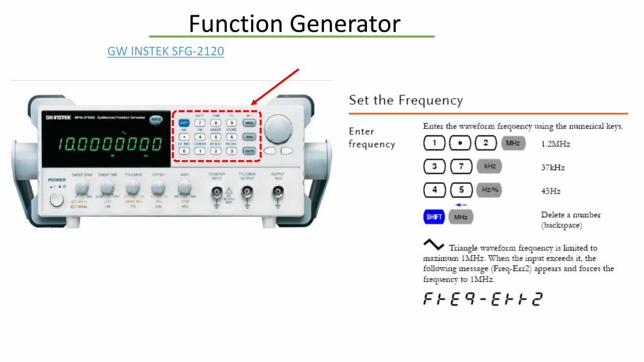
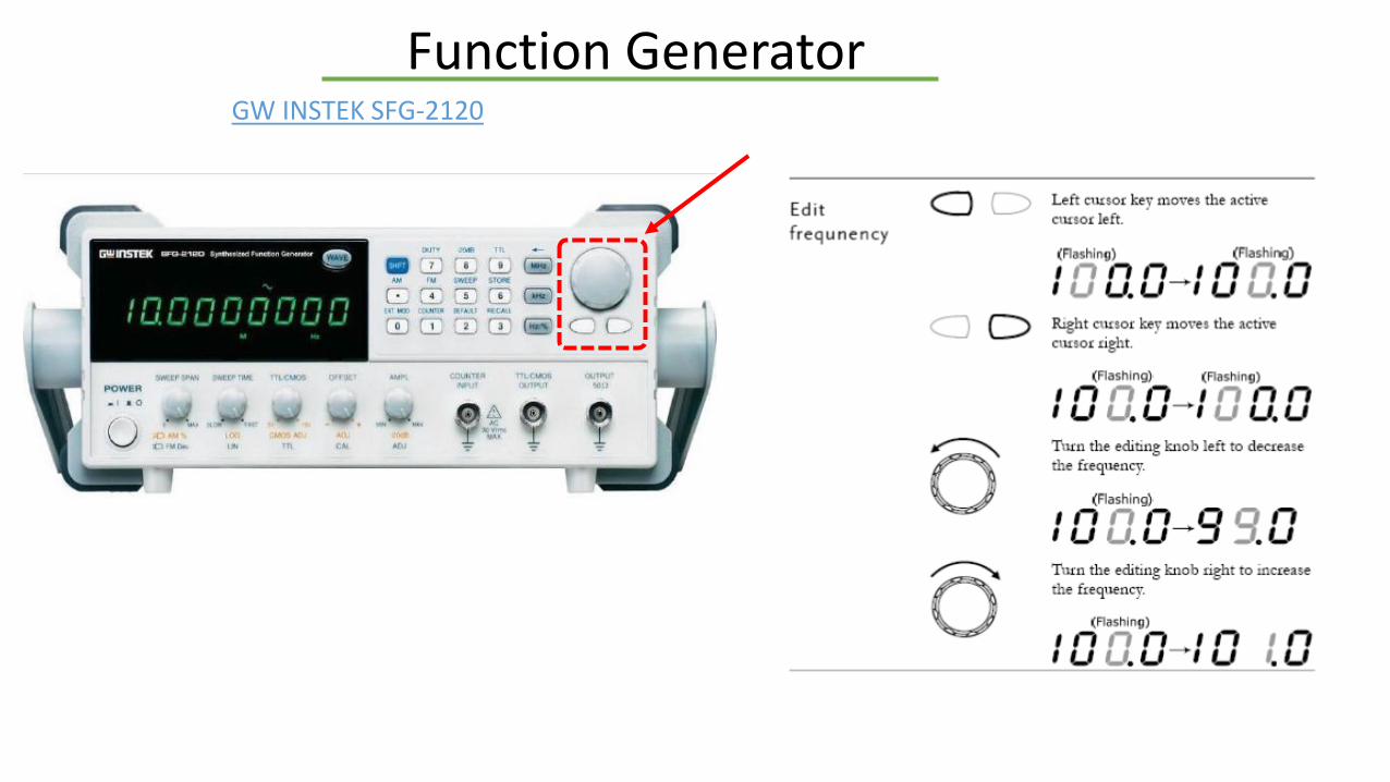
GW INSTEK SFG-2120
SPECIFICATIONS

Function GeneratorGW INSTEK SFG-2120
Function GeneratorGW INSTEK SFG-2120
Function GeneratorGW INSTEK SFG-2120

Function GeneratorGW INSTEK SFG-2120
2DEFAULT
DEFAULT Settings

Oscilloscope
• Frequency: DC-100MHz• 2 Channels• 1 M Ohm input impedance• FFT, A*B, A+B, A-B• Digital Measurements (Vpp, Vdc, Frequency...)• Saving Graphical Data (SD Card Interface)
SPECIFICATIONS
DIGITAL OSCILLOSCOPE GW Instek GDS-1102
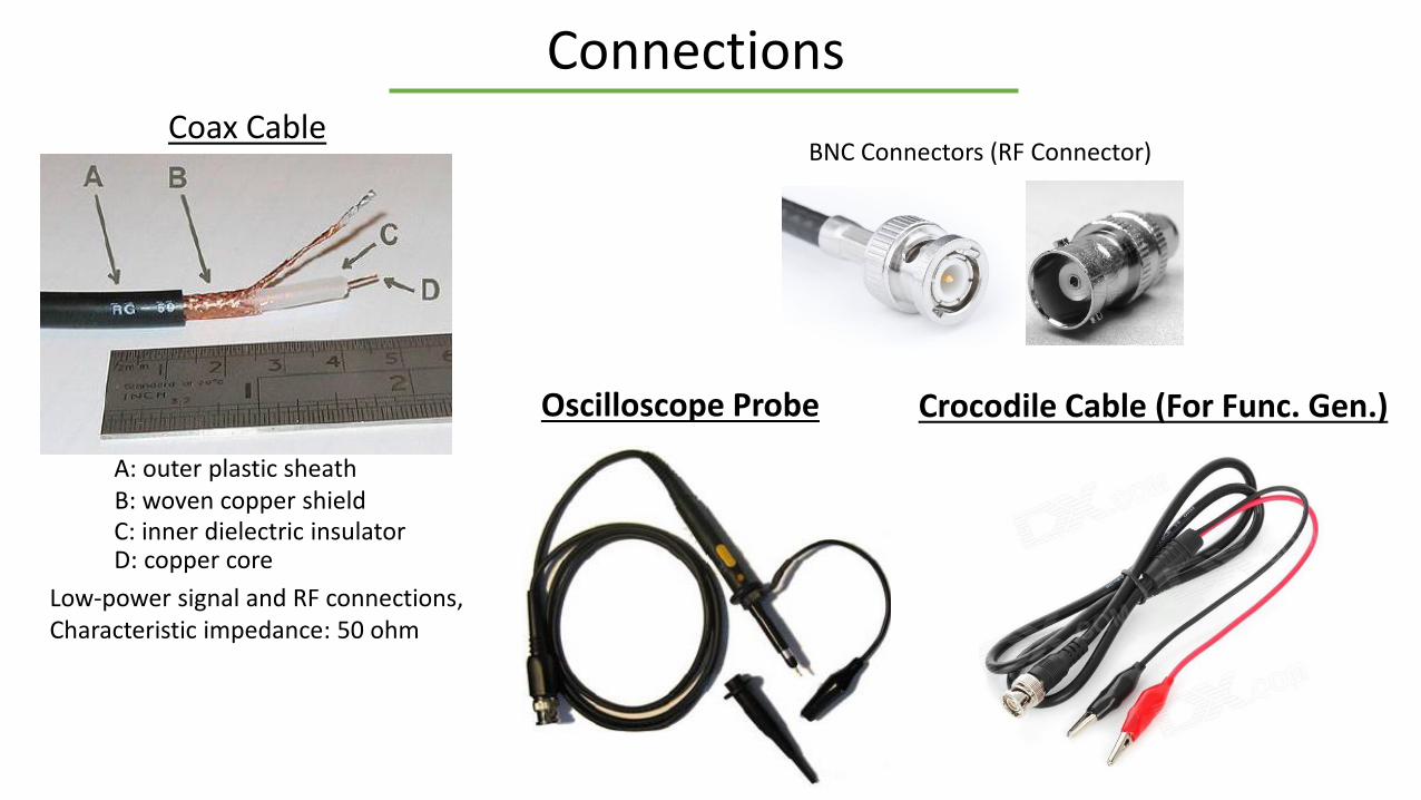
Connections
BNC Connectors (RF Connector)Coax Cable
Low-power signal and RF connections,Characteristic impedance: 50 ohm
A: outer plastic sheathB: woven copper shieldC: inner dielectric insulatorD: copper core
Oscilloscope Probe Crocodile Cable (For Func. Gen.)
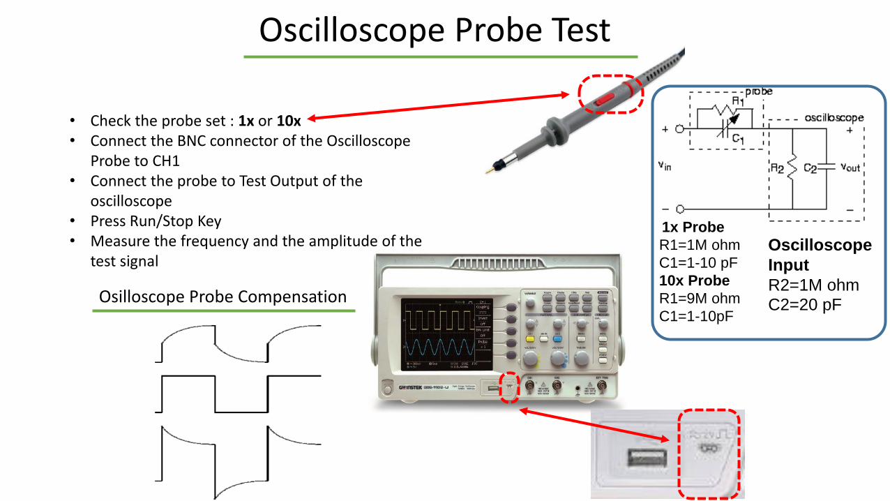
Oscilloscope Probe Test
Osilloscope Probe Compensation
1x Probe
R1=1M ohm
C1=1-10 pF
10x Probe
R1=9M ohm
C1=1-10pF
Oscilloscope
Input
R2=1M ohm
C2=20 pF
• Check the probe set : 1x or 10x• Connect the BNC connector of the Oscilloscope
Probe to CH1• Connect the probe to Test Output of the
oscilloscope• Press Run/Stop Key• Measure the frequency and the amplitude of the
test signal
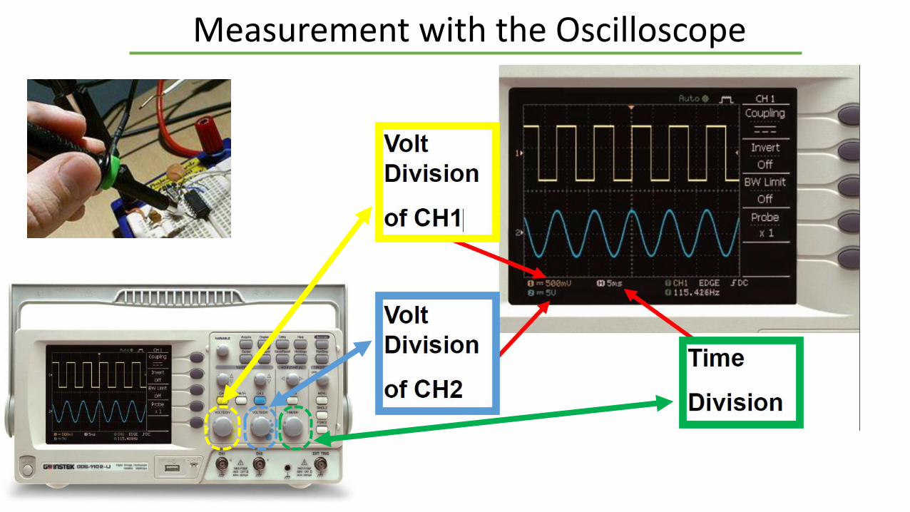
Measurement with the Oscilloscope

1st Job:
• A(t)=5.sin(100pt)
–Amplitude: ………. • peak (p) : ……….• peak-to-peak (pp) : ……….
–Time period (seconds) : ……….–Frequency (Hertz) : ……….
• Derive the sine signal using function generatorand monitore with the oscilloscope

2nd Job:
Generate:• 4 V (p-p) • 10 kHz Square Wave, Sine Wave and Triangular Wave
• Derive the signals using function generator andmonitore with the oscilloscope

3rd Job:
Generate:• 100 mV (p-p) • 1 kHz Square Wave, Sine Wave and Triangular Wave
• Derive the signals using function generator andmonitore with the oscilloscope

The Usage of Cursors
Determination of time periode using Cursor function. (Step1)
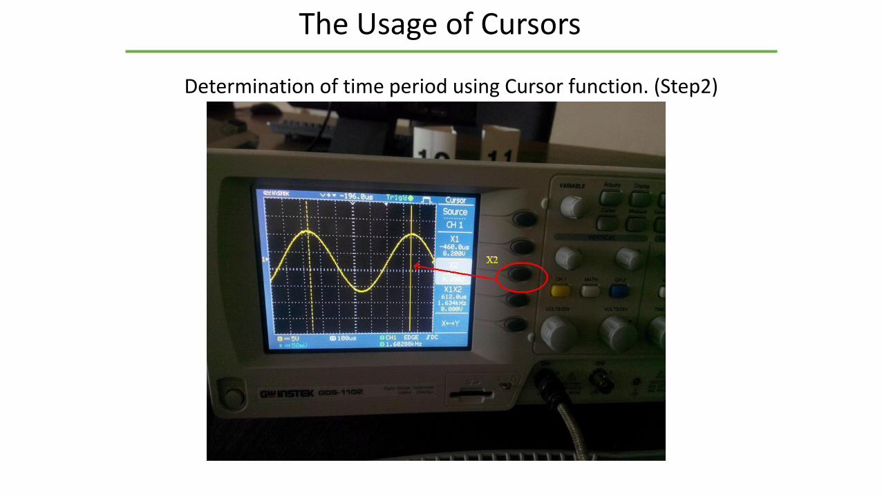
The Usage of Cursors
Determination of time period using Cursor function. (Step2)
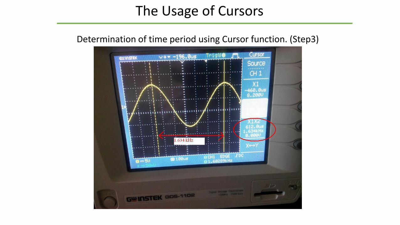
The Usage of Cursors
Determination of time period using Cursor function. (Step3)